Embed Size (px)
Citation preview

1
ww
w.blackanddecker.com
UK
Ireland
Australia
New Zealand
2
1
3
17
17
2
1
3
10
9
14
16
4
8
7
11
15
12
4
8
7
11
12
10 13 9
5
6
5
6
2
5 11
6
24
12 25
13 2-3 mm
2-3 mm
23
C
BA
D
21
20 19
18
22
3
15
1433
322930 31
8 7
11
28
2627
FE
G
4
Intended useYour Black & Decker saw has been designed for sawing woodand wood products.This tool is intended for consumer use only.
General safety rulesWarning! Read all instructions. Failure to follow all instructionslisted below may result in electric shock, fire and/or seriousinjury. The term “power tool” in all of the warnings listedbelow refers to your mains operated (corded) power tool orbattery operated (cordless) power tool.SAVE THESE INSTRUCTIONS.
1. Work areaa. Keep work area clean and well lit. Cluttered and dark
areas invite accidents.b. Do not operate power tools in explosive atmospheres,
such as in the presence of flammable liquids, gasesor dust. Power tools create sparks which may ignite thedust or fumes.
c. Keep children and bystanders away whileoperating a power tool. Distractions can cause you tolose control.
2. Electrical safetya. Power tool plugs must match the outlet. Never modify
the plug in any way. Do not use any adapter plugswith earthed (grounded) power tools. Unmodifiedplugs and matching outlets will reduce risk of electric shock.
b. Avoid body contact with earthed or groundedsurfaces such as pipes, radiators, ranges andrefrigerators. There is an increased risk of electric shockif your body is earthed or grounded.
c. Do not expose power tools to rain or wet conditions.Water entering a power tool will increase the risk ofelectric shock.
d. Do not abuse the cord. Never use the cord forcarrying, pulling or unplugging the power tool.Keep cord away from heat, oil, sharp edges ormoving parts. Damaged or entangled cords increase therisk of electric shock.
e. When operating a power tool outdoors, use anextension cord suitable for outdoor use. Use of a cordsuitable for outdoor use reduces the risk of electric shock.
3. Personal safetya. Stay alert, watch what you are doing and use common
sense when operating a power tool. Do not use apower tool while you are tired or under the influenceof drugs, alcohol or medication. A moment ofinattention while operating power tools may result inserious personal injury.
b. Use safety equipment. Always wear eye protection.Safety equipment such as dust mask, non-skid safetyshoes, hard hat, or hearing protection used forappropriate conditions will reduce personal injuries.
c. Avoid accidental starting. Ensure the switch is inthe off position before plugging in. Carrying powertools with your finger on the switch or plugging in powertools that have the switch on invites accidents.
d. Remove any adjusting key or wrench before turningthe power tool on. A wrench or a key left attached to arotating part of the power tool may result in personal injury.
e. Do not overreach. Keep proper footing and balanceat all times. This enables better control of the power toolin unexpected situations.
f. Dress properly. Do not wear loose clothing orjewellery. Keep your hair, clothing and gloves awayfrom moving parts. Loose clothes, jewellery or long haircan be caught in moving parts.
g. If devices are provided for the connection of dustextraction and collection facilities, ensure theseare connected and properly used. Use of thesedevices can reduce dust related hazards.
4. Power tool use and carea. Do not force the power tool. Use the correct power
tool for your application. The correct power tool will dothe job better and safer at the rate for which it was designed.
b. Do not use the power tool if the switch does notturn it on and off. Any power tool that cannot be controlledwith the switch is dangerous and must be repaired.
c. Disconnect the plug from the power source beforemaking any adjustments, changing accessories, orstoring power tools. Such preventive safety measuresreduce the risk of starting the power tool accidentally.
d. Store idle power tools out of the reach of childrenand do not allow persons unfamiliar with the powertool or these instructions to operate the power tool.Power tools are dangerous in the hands of untrained users.
e. Maintain power tools. Check for misalignment orbinding of moving parts, breakage of parts and anyother condition that may affect the power toolsoperation. If damaged, have the power tool repairedbefore use. Many accidents are caused by poorlymaintained power tools.
f. Keep cutting tools sharp and clean. Properly maintainedcutting tools with sharp cutting edges are less likely tobind and are easier to control.
5
g. Use the power tool, accessories and tool bits etc.,in accordance with these instructions and in themanner intended for the particular type of powertool, taking into account the working conditionsand the work to be performed. Use of the power toolfor operations different from those intended could resultin a hazardous situation.
5. Servicea. Have your power tool serviced by a qualified repair
person using only identical replacement parts. Thiswill ensure that the safety of the power tool is maintained.
Safety instructions for all saws
Danger:
� Keep hands away from cutting area and the blade.Keep your second hand on auxiliary handle, ormotor housing. If both hands are holding the saw, theycannot be cut by the blade.
� Do not reach underneath the workpiece. The guardcannot protect you from the blade below the workpiece.
� Adjust the cutting depth to the thickness of theworkpiece. Less than a full tooth of the blade teethshould be visible below the workpiece.
� Never hold piece being cut in your hands or acrossyour leg. Secure the workpiece to a stable platform.It is important to support the work properly to minimizebody exposure, blade binding, or loss of control.
� Hold power tool by insulated gripping surfaceswhen performing an operation where the cuttingtool may contact hidden wiring or its own cord.Contact with a “live” wire will also make exposed metalparts of the power tool “live” and shock the operator.
� When ripping always use a rip fence or straightedge guide. This improves the accuracy of cut andreduces the chance of blade binding.
� Always use blades with correct size and shape(diamond versus round) of arbour holes. Blades thatdo not match the mounting hardware of the saw will runeccentrically, causing loss of control.
� Never use damaged or incorrect blade washers orbolt. The blade washers and bolt were specially designedfor your saw, for optimum performance and safety ofoperation.
Further safety instructions for all sawsCauses and operator prevention of kickback:– kickback is a sudden reaction to a pinched, bound or
misaligned saw blade, causing an uncontrolled saw to liftup and out of the workpiece toward the operator;
– when the blade is pinched or bound tightly by the kerfclosing down, the blade stalls and the motor reactiondrives the unit rapidly back toward the operator;
– if the blade becomes twisted or misaligned in the cut, theteeth at the back edge of the blade can dig into the topsurface of the wood causing the blade to climb out of thekerf and jump back toward the operator.
Kickback is the result of saw misuse and/or incorrectoperating procedures or conditions and can be avoided bytaking proper precautions as given below.
� Maintain a firm grip with both hands on the sawand position your arms to resist kickback forces.Position your body to either side of the blade, butnot in line with the blade. Kickback could cause thesaw to jump backwards, but kickback forces can becontrolled by the operator, if proper precautions are taken.
� When blade is binding, or when interrupting a cutfor any reason, release the trigger and hold the sawmotionless in the material until the blade comes toa complete stop. Never attempt to remove the sawfrom the work or pull the saw backward while theblade is in motion or kickback may occur. Investigateand take corrective actions to eliminate the cause ofblade binding.
� When restarting a saw in the workpiece, centre thesaw blade in the kerf and check that saw teeth arenot engaged into the material. If saw blade is binding,it may walk up or kickback from the workpiece as the sawis restarted.
� Support large panels to minimise the risk of bladepinching and kickback. Large panels tend to sag undertheir own weight. Supports must be placed under thepanel on both sides, near the line of cut and near theedge of the panel.
� Do not use dull or damaged blades. Unsharpened orimproperly set blades produce narrow kerf causingexcessive friction, blade binding and kickback.
� Blade depth and bevel adjusting locking levers mustbe tight and secure before making cut. If bladeadjustment shifts while cutting, it may cause binding andkickback.
� Use extra caution when making a “plunge cut” intoexisting walls or other blind areas. The protrudingblade may cut objects that can cause kickback.
6
Safety instructions for saws with a pendulum blade guard� Check lower guard for proper closing before each
use. Do not operate the saw if lower guard does notmove freely and close instantly. Never clamp or tiethe lower guard into the open position. If saw isaccidentally dropped, lower guard may be bent.Raise the lower guard with the retracting handle andmake sure it moves freely and does not touch the blade orany other part, in all angles and depths of cut.
� Check the operation of the lower guard spring. Ifthe guard and the spring are not operating properly,they must be serviced before use. Lower guard mayoperate sluggishly due to damaged parts, gummydeposits, or a build-up of debris.
� Lower guard should be retracted manually only forspecial cuts such as “plunge cuts” and “compoundcuts.” Raise lower guard by retracting handle andas soon as blade enters the material, the lowerguard must be released. For all other sawing, the lowerguard should operate automatically.
� Always observe that the lower guard is coveringthe blade before placing saw down on bench orfloor. An unprotected, coasting blade will cause the sawto walk backwards, cutting whatever is in its path. Beaware of the time it takes for the blade to stop afterswitch is released.
Additional safety instructions for all saws with riving knife� Use the appropriate riving knife for the blade being
used. For the riving knife to work, it must be thicker thanthe body of the blade but thinner than the tooth set of theblade.
� Adjust the riving knife as described in this instructionmanual. Incorrect spacing, positioning and alignment canmake the riving knife ineffective in preventing kickback.
� Always use the riving knife except when plungecutting. Riving knife must be replaced after plunge cutting.Riving knife causes interference during plunge cutting andcan create kickback.
� For the riving knife to work, it must be engaged inthe workpiece. The riving knife is ineffective inpreventing kickback during short cuts.
� Do not operate the saw if riving knife is bent. Even alight interference can slow the closing rate of a guard.
Additional safety instructions for circular saws� Wear ear protectors. Exposure to noise can cause hearing
loss.� Preferably wear a dust mask.
� Do not use blades of larger or smaller diameter thanrecommended. For the proper blade rating refer to thetechnical data. Use only the blades specified in thismanual, complying with EN 847-1.
� Never use abrasive cut-off wheels.
Electrical safety
This tool is double insulated; therefore no earth wireis required. Always check that the power supplycorresponds to the voltage on the rating plate.
� This appliance is not intended for use by young or infirmpersons without supervision. Children must be supervisedto ensure they do not play with the appliance.
� If the supply cord is damaged, it must be replaced by themanufacturer or an authorised Black & Decker ServiceCentre in order to avoid a hazard.
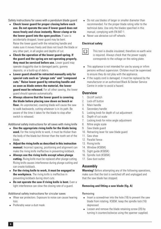
Overview1. On/off switch2. Lock-off button3. Main handle4. Secondary handle5. Locking knob for depth of cut adjustment6. Depth of cut scale7. Locking knob for mitre angle adjustment8. Mitre angle scale9. Saw blade guard10. Retracting lever for saw blade guard11. Saw shoe12. Parallel fence13. Riving knife14. Window (KS65K)15. Sight guide (KS65K)16. Spindle lock (KS65K)17. Saw dust outlet
AssemblyWarning! Before attempting any of the following operations,make sure that the tool is switched off and unplugged andthat the saw blade has stopped.
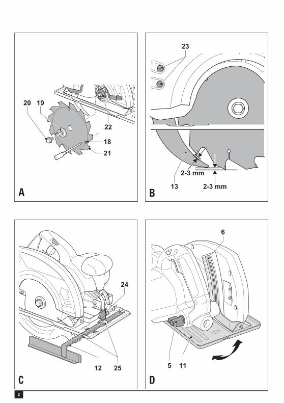
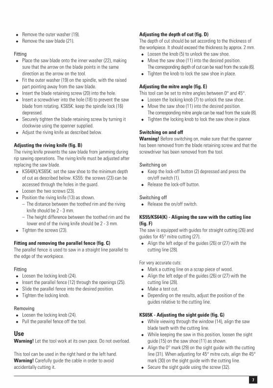
Removing and fitting a saw blade (fig. A)
Removing� Insert a screwdriver into the hole (18) to prevent the saw
blade from rotating. KS65K: keep the spindle lock (16)depressed.
� Loosen and remove the blade retaining screw (20) byturning it counterclockwise using the spanner supplied.
7
� Remove the outer washer (19).� Remove the saw blade (21).
Fitting� Place the saw blade onto the inner washer (22), making
sure that the arrow on the blade points in the samedirection as the arrow on the tool.
� Fit the outer washer (19) on the spindle, with the raisedpart pointing away from the saw blade.
� Insert the blade retaining screw (20) into the hole.� Insert a screwdriver into the hole (18) to prevent the saw
blade from rotating. KS65K: keep the spindle lock (16)depressed.
� Securely tighten the blade retaining screw by turning itclockwise using the spanner supplied.
� Adjust the riving knife as described below.
Adjusting the riving knife (fig. B)The riving knife prevents the saw blade from jamming duringrip sawing operations. The riving knife must be adjusted afterreplacing the saw blade.
� KS64(K)/KS65K: set the saw shoe to the minimum depthof cut as described below. KS55: the screws (23) can beaccessed through the holes in the guard.
� Loosen the two screws (23).� Position the riving knife (13) as shown.
– The distance between the toothed rim and the rivingknife should be 2 - 3 mm.
– The height difference between the toothed rim and thelower end of the riving knife should be 2 - 3 mm.
� Tighten the screws (23).
Fitting and removing the parallel fence (fig. C)The parallel fence is used to saw in a straight line parallel tothe edge of the workpiece.
Fitting� Loosen the locking knob (24).� Insert the parallel fence (12) through the openings (25).� Slide the parallel fence into the desired position.� Tighten the locking knob.
Removing� Loosen the locking knob (24).� Pull the parallel fence off the tool.
UseWarning! Let the tool work at its own pace. Do not overload.
This tool can be used in the right hand or the left hand.Warning! Carefully guide the cable in order to avoidaccidentally cutting it.
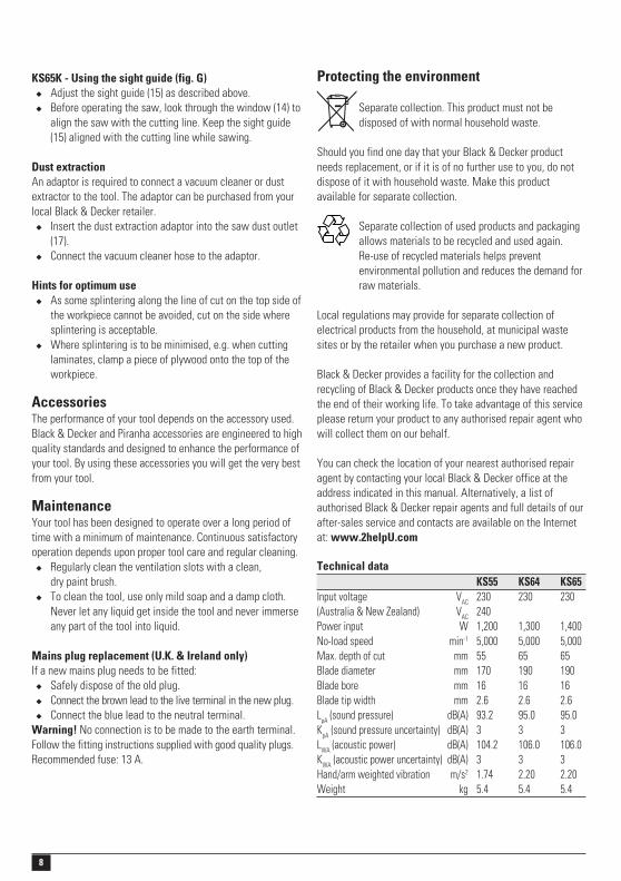
Adjusting the depth of cut (fig. D)The depth of cut should be set according to the thickness ofthe workpiece. It should exceed the thickness by approx. 2 mm.
� Loosen the knob (5) to unlock the saw shoe.� Move the saw shoe (11) into the desired position.
The corresponding depth of cut can be read from the scale (6).� Tighten the knob to lock the saw shoe in place.
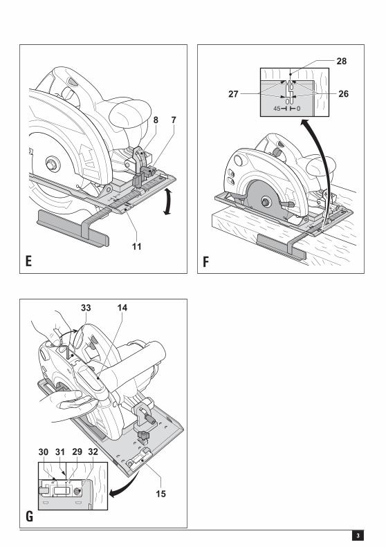
Adjusting the mitre angle (fig. E)This tool can be set to mitre angles between 0° and 45°.
� Loosen the locking knob (7) to unlock the saw shoe.� Move the saw shoe (11) into the desired position.
The corresponding mitre angle can be read from the scale (8).� Tighten the locking knob to lock the saw shoe in place.
Switching on and offWarning! Before switching on, make sure that the spannerhas been removed from the blade retaining screw and that thescrewdriver has been removed from the tool.
Switching on� Keep the lock-off button (2) depressed and press the
on/off switch (1).� Release the lock-off button.
Switching off� Release the on/off switch.
KS55/KS64(K) - Aligning the saw with the cutting line(fig. F)The saw is equipped with guides for straight cutting (26) andguides for 45° mitre cutting (27).
� Align the left edge of the guides (26) or (27) with thecutting line (28).
For very accurate cuts:� Mark a cutting line on a scrap piece of wood.� Align the left edge of the guides (26) or (27) with the
cutting line (28).� Make a test cut.� Depending on the results, adjust the position of the
guides relative to the cutting line.
KS65K - Adjusting the sight guide (fig. G)� While viewing through the window (14), align the saw
blade teeth with the cutting line.� While keeping the saw in this position, loosen the sight
guide (15) on the saw shoe (11) as shown.� Align the 0° mark (29) on the sight guide with the cutting
line (31). When adjusting for 45° mitre cuts, align the 45°mark (30) on the sight guide with the cutting line.
� Secure the sight guide using the screw (32).
8
KS65K - Using the sight guide (fig. G)� Adjust the sight guide (15) as described above.� Before operating the saw, look through the window (14) to
align the saw with the cutting line. Keep the sight guide(15) aligned with the cutting line while sawing.
Dust extractionAn adaptor is required to connect a vacuum cleaner or dustextractor to the tool. The adaptor can be purchased from yourlocal Black & Decker retailer.
� Insert the dust extraction adaptor into the saw dust outlet(17).
� Connect the vacuum cleaner hose to the adaptor.
Hints for optimum use� As some splintering along the line of cut on the top side of
the workpiece cannot be avoided, cut on the side wheresplintering is acceptable.
� Where splintering is to be minimised, e.g. when cuttinglaminates, clamp a piece of plywood onto the top of theworkpiece.
AccessoriesThe performance of your tool depends on the accessory used.Black & Decker and Piranha accessories are engineered to highquality standards and designed to enhance the performance ofyour tool. By using these accessories you will get the very bestfrom your tool.
MaintenanceYour tool has been designed to operate over a long period oftime with a minimum of maintenance. Continuous satisfactoryoperation depends upon proper tool care and regular cleaning.
� Regularly clean the ventilation slots with a clean,dry paint brush.
� To clean the tool, use only mild soap and a damp cloth.Never let any liquid get inside the tool and never immerseany part of the tool into liquid.
Mains plug replacement (U.K. & Ireland only)If a new mains plug needs to be fitted:
� Safely dispose of the old plug.� Connect the brown lead to the live terminal in the new plug.� Connect the blue lead to the neutral terminal.
Warning! No connection is to be made to the earth terminal.Follow the fitting instructions supplied with good quality plugs.Recommended fuse: 13 A.
Protecting the environment
Separate collection. This product must not bedisposed of with normal household waste.
Should you find one day that your Black & Decker productneeds replacement, or if it is of no further use to you, do notdispose of it with household waste. Make this productavailable for separate collection.
Separate collection of used products and packagingallows materials to be recycled and used again.Re-use of recycled materials helps preventenvironmental pollution and reduces the demand forraw materials.
Local regulations may provide for separate collection ofelectrical products from the household, at municipal wastesites or by the retailer when you purchase a new product.
Black & Decker provides a facility for the collection andrecycling of Black & Decker products once they have reachedthe end of their working life. To take advantage of this serviceplease return your product to any authorised repair agent whowill collect them on our behalf.
You can check the location of your nearest authorised repairagent by contacting your local Black & Decker office at theaddress indicated in this manual. Alternatively, a list ofauthorised Black & Decker repair agents and full details of ourafter-sales service and contacts are available on the Internetat: www.2helpU.com
Technical dataKS55 KS64 KS65
Input voltage VAC 230 230 230(Australia & New Zealand) VAC 240Power input W 1,200 1,300 1,400No-load speed min-1 5,000 5,000 5,000Max. depth of cut mm 55 65 65Blade diameter mm 170 190 190Blade bore mm 16 16 16Blade tip width mm 2.6 2.6 2.6LpA (sound pressure) dB(A) 93.2 95.0 95.0KpA (sound pressure uncertainty) dB(A) 3 3 3LWA (acoustic power) dB(A) 104.2 106.0 106.0KWA (acoustic power uncertainty) dB(A) 3 3 3Hand/arm weighted vibration m/s2 1.74 2.20 2.20Weight kg 5.4 5.4 5.4

9
EC declaration of conformityKS55/KS64/KS65
Black & Decker declares that these products conform to:98/37/EC, 89/336/EEC, EN 60745, EN 55014, EN 61000
Kevin HewittDirector of Consumer Engineering
Spennymoor, County Durham DL16 6JG,United Kingdom
1-5-2006GuaranteeBlack & Decker is confident of the quality of its products andoffers an outstanding guarantee. This guarantee statement isin addition to and in no way prejudices your statutory rights.The guarantee is valid within the territories of the MemberStates of the European Union and the European Free TradeArea.
If a Black & Decker product becomes defective due to faultymaterials, workmanship or lack of conformity, within 24 monthsfrom the date of purchase, Black & Decker guarantees toreplace defective parts, repair products subjected to fair wearand tear or replace such products to ensure minimuminconvenience to the customer unless:
� The product has been used for trade, professional or hirepurposes;
� The product has been subjected to misuse or neglect;� The product has sustained damage through foreign
objects, substances or accidents;� Repairs have been attempted by persons other than
authorised repair agents or Black & Decker service staff.
To claim on the guarantee, you will need to submit proof ofpurchase to the seller or an authorised repair agent. You cancheck the location of your nearest authorised repair agent bycontacting your local Black & Decker office at the addressindicated in this manual. Alternatively, a list of authorisedBlack & Decker repair agents and full details of our after-salesservice and contacts are available on the Internet at:www.2helpU.com.
Please register at our website www.blackanddecker.comto be kept up to date on new products and special offers.Further information on the Black & Decker brand and our rangeof products is available at www.blackanddecker.com.
10
TYP
WWW.2helpU.com 16 - 07 - 01E13203
KS55 KS64 1
KS64 821
817
KS55
KS55
24
3 2019
35
14
15
23
22
3
16
3
51
52
29
37
3938
6
1
2 7
10
40
4
36
535
41
42
25
28
27
30
34
33
49
32
3143
4650
30
2.5
2.0
54
21
9
KS64
55
55
5657
1317
18
816

11
TYP
WWW.2helpU.com 23 - 07 - 01E13216
KS65K 1
821
817
24
3 2019
14
15
23
223
16
3
51
52
29
37
3938
9
6
1
2 7
10
40
41
42
25
28
27
49
32
50
30
2.5
2.0
21
3143
46
34
3354
7675
5
58
61
59
60
71
53
5657
55
3655
4
66
6563
64
67
68
6970
7877
62
816
72
7374
1317
18

12
573644-03 05/06
AustraliaBlack & Decker (Australia) Pty. Ltd. Tel. 03-8720 510020 Fletcher Road, Mooroolbark, Fax 03-9727 5940Victoria, 3138
New ZealandBlack & Decker Tel. 09 579 760081 Hugo Johnston Drive Fax 09 579 8200Penrose, Auckland, New Zealand
United KingdomBlack & Decker Tel. 01753 511234210 Bath Road Fax 01753 551155Slough, Berkshire SL1 3YD Helpline 01753 574277