Embed Size (px)
Citation preview

PMA Prozeß- und Maschinen-Automation GmbH
Industrial Controller KS 40-1,KS 41-1 and KS 42-1
40KS
KKS
KS4KS40
KS 40-1
KS 41-1
KS 42-1
MODBUSInterfacedescription
MODBUS-protocol
9499 040 63511
Valid from: 02/2005

MODBUS®
is a registered trademark of the MODBUS-IDA Organization
BluePort®
and BlueControl®
are registered trademarks of PMA Prozeß- und Maschinen-Automation GmbH
© 2004- 2005 PMA Prozeß- und Maschinen-Automation GmbH • Printed in Germany • All rightsreserved • Without prior written consent, reprinting or photocopying of this document, entirelyor in part, is prohibited.
This is a publication ofPMA Prozeß- und Maschinen AutomationP.O. Box 310229D-34058 KasselGermany
Explanation of symbols:
g General information
a General warning
l Caution: ESD-sensitive components
KS 40-1, KS 41-1,KS 42-1 MODBUS 3
Content
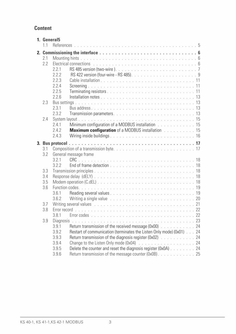
1. General51.1 References . . . . . . . . . . . . . . . . . . . . . . . . . . . . . . . . . . . . . . . 5
2. Commissioning the interface . . . . . . . . . . . . . . . . . . . . . . . . . . . . . . . 62.1 Mounting hints . . . . . . . . . . . . . . . . . . . . . . . . . . . . . . . . . . . . . 62.2 Electrical connections . . . . . . . . . . . . . . . . . . . . . . . . . . . . . . . . . 6
2.2.1 RS 485 version (two-wire ) . . . . . . . . . . . . . . . . . . . . . . . . . . 72.2.2 RS 422 version (four-wire - RS 485) . . . . . . . . . . . . . . . . . . . . . 92.2.3 Cable installation . . . . . . . . . . . . . . . . . . . . . . . . . . . . . . 112.2.4 Screening . . . . . . . . . . . . . . . . . . . . . . . . . . . . . . . . . . 112.2.5 Terminating resistors . . . . . . . . . . . . . . . . . . . . . . . . . . . . 112.2.6 Installation notes . . . . . . . . . . . . . . . . . . . . . . . . . . . . . . 13
2.3 Bus settings . . . . . . . . . . . . . . . . . . . . . . . . . . . . . . . . . . . . . . 132.3.1 Bus address . . . . . . . . . . . . . . . . . . . . . . . . . . . . . . . . . 132.3.2 Transmission parameters . . . . . . . . . . . . . . . . . . . . . . . . . . 13
2.4 System layout . . . . . . . . . . . . . . . . . . . . . . . . . . . . . . . . . . . . . 152.4.1 Minimum configuration of a MODBUS installation . . . . . . . . . . . . 15
2.4.2 Maximum configuration of a MODBUS installation . . . . . . . . . . 152.4.3 Wiring inside buildings . . . . . . . . . . . . . . . . . . . . . . . . . . . 16
3. Bus protocol . . . . . . . . . . . . . . . . . . . . . . . . . . . . . . . . . . . . . . . . 173.1 Composition of a transmission byte. . . . . . . . . . . . . . . . . . . . . . . . . . 173.2 General message frame . . . . . . . . . . . . . . . . . . . . . . . . . . . . . . . . 17
3.2.1 CRC . . . . . . . . . . . . . . . . . . . . . . . . . . . . . . . . . . . . . 183.2.2 End of frame detection . . . . . . . . . . . . . . . . . . . . . . . . . . . 18
3.3 Transmission principles . . . . . . . . . . . . . . . . . . . . . . . . . . . . . . . . 183.4 Response delay (dELY) . . . . . . . . . . . . . . . . . . . . . . . . . . . . . . . . 183.5 Modem operation (C.dEL) . . . . . . . . . . . . . . . . . . . . . . . . . . . . . . . 183.6 Function codes. . . . . . . . . . . . . . . . . . . . . . . . . . . . . . . . . . . . . 19
3.6.1 Reading several values . . . . . . . . . . . . . . . . . . . . . . . . . . . 193.6.2 Writing a single value . . . . . . . . . . . . . . . . . . . . . . . . . . . 20
3.7 Writing several values . . . . . . . . . . . . . . . . . . . . . . . . . . . . . . . . 213.8 Error record . . . . . . . . . . . . . . . . . . . . . . . . . . . . . . . . . . . . . . 22
3.8.1 Error codes . . . . . . . . . . . . . . . . . . . . . . . . . . . . . . . . . 223.9 Diagnosis . . . . . . . . . . . . . . . . . . . . . . . . . . . . . . . . . . . . . . . 23
3.9.1 Return transmission of the received message (0x00) . . . . . . . . . . . 243.9.2 Restart of communication (terminates the Listen Only mode) (0x01) . . . 243.9.3 Return transmission of the diagnosis register (0x02) . . . . . . . . . . . 243.9.4 Change to the Listen Only mode (0x04) . . . . . . . . . . . . . . . . . . 243.9.5 Delete the counter and reset the diagnosis register (0x0A) . . . . . . . . 243.9.6 Return transmission of the message counter (0x0B) . . . . . . . . . . . . 25
4 KS 40-1, KS 41-1,KS 42-1 MODBUS
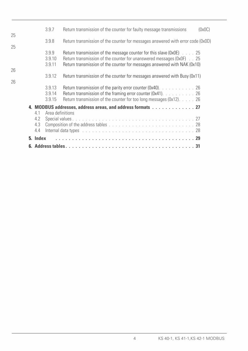
3.9.7 Return transmission of the counter for faulty message transmissions (0x0C)25
3.9.8 Return transmission of the counter for messages answered with error code (0x0D)25
3.9.9 Return transmission of the message counter for this slave (0x0E) . . . . 253.9.10 Return transmission of the counter for unanswered messages (0x0F) . . 253.9.11 Return transmission of the counter for messages answered with NAK (0x10)
263.9.12 Return transmission of the counter for messages answered with Busy (0x11)
263.9.13 Return transmission of the parity error counter (0x40) . . . . . . . . . . . 263.9.14 Return transmission of the framing error counter (0x41). . . . . . . . . . 263.9.15 Return transmission of the counter for too long messages (0x12) . . . . . 26
4. MODBUS addresses, address areas, and address formats . . . . . . . . . . . . . 274.1 Area definitions . . . . . . . . . . . . . . . . . . . . . . . . . . . . . . . . . . . . 274.2 Special values . . . . . . . . . . . . . . . . . . . . . . . . . . . . . . . . . . . . . 274.3 Composition of the address tables . . . . . . . . . . . . . . . . . . . . . . . . . . 284.4 Internal data types . . . . . . . . . . . . . . . . . . . . . . . . . . . . . . . . . . 28
5. Index . . . . . . . . . . . . . . . . . . . . . . . . . . . . . . . . . . . . . . . . . . 29
6. Address tables . . . . . . . . . . . . . . . . . . . . . . . . . . . . . . . . . . . . . . . 31
. 1 General
We thank you for purchasing a device from the BluePort® product range. This document describes the implementationand operation of the MODBUS interface used with the industrial controller KS 40-1 which will be called ‘device’ in therest of this document.This document is also valid for KS 41-1 and KS 42-1.
Devices with a MODBUS interface permit the transmission of process data, parameters, and configuration data.Electrical connections are made at the base of the device in the channel of the top-hat DIN rail. The serialcommunication interface provides a simple link to superordinate PLCs, visualization tools, etc.
An additional interface that is always fitted in the device’s front panel is the BluePort® (PC) interface. This interface isnot bussable, and serves for a direct connection with the BlueControl® software package that runs on a PC or laptop.Communication is done according to the master/slave principle. The device is always operated as a slave.
The most important characteristics and physical/electrical properties of the bus connection are:
• Network topology
linear bus, possible with bus termination at both ends (see below).
• Transmission media
screened and twisted 2-wire copper leads
• Lead lengths (without repeater)
A maximum lead length of 1000 m should not be exceeded.
• Transmission speeds
The following transmission speeds are supported:
2400 … 38400 bits/s
• Physical interface
RS 485 with bus connections in the top-hat rail; connections made on site.
• Address range
1 ... 247(32 devices in one segment. Expandable to 247 with repeaters.)
1.1 References
Further information on the MODBUS-Protokoll:[1] MODBUS Specifications
– MODBUS application Protocol Specification V1,1– MODBUS over serial line specification and implementation guide V1.1– http://www.modbus.org
Further information on RS 485:[2] ANSI/TIA/EIA-485-A
Additional documentation for KS 4x-1 devices:[3] Industrial controller KS 40-1 / KS 41-1 / KS 42-1
– Data sheet KS 40-1/41-1/42-1 9498 737 39913– Operating instructions KS 40-1/41-1/42-1 9499 040 62711
General
KS 40-1, KS 41-1,KS 42-1 MODBUS 5 References

. 2 Commissioning the interface
Instrument field bus connection is via the pins of connector B on the rear, via flat-pin connectors or via screw terminalsdependent on version.Construction of suitable cables must be done by the user.
2.1 Mounting hints
If possible, the place of installation should be exempt of vibration, aggressive media (e.g. acid, lye), liquid, dust oraerosol.
a The unit may be operated only in environments for which it is suitable due to its protection type.
a The housing ventilation slots must not be covered.
a In plants where transient voltage peaks are susceptible to occur, the instruments must be equipped withadditional protective filters or voltage limiters!
l Caution! The instrument contains electrostatically sensitive components.
a Please, follow the instructions given in the safety hints.
2.2 Electrical connections
The electrical connection of the interface can be done as two-wire RS 485, as well as four-wire RS 485 (often called RS 422).
Commissioning the interface
Mounting hints 6 KS 40-1, KS 41-1,KS 42-1 MODBUS
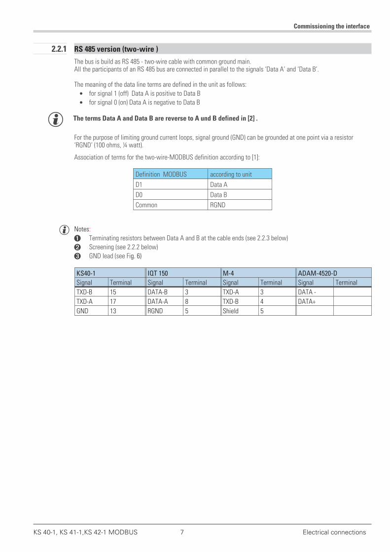
2.2.1 RS 485 version (two-wire )
The bus is build as RS 485 - two-wire cable with common ground main.All the participants of an RS 485 bus are connected in parallel to the signals ‘Data A’ and ‘Data B’.
The meaning of the data line terms are defined in the unit as follows:
• for signal 1 (off) Data A is positive to Data B
• for signal 0 (on) Data A is negative to Data B
g The terms Data A and Data B are reverse to A und B defined in [2] .
For the purpose of limiting ground current loops, signal ground (GND) can be grounded at one point via a resistor‘RGND’ (100 ohms, ¼ watt).
Association of terms for the two-wire-MODBUS definition according to [1]:
Definition MODBUS according to unit
D1 Data A
D0 Data B
Common RGND
g Notes:
1 Terminating resistors between Data A and B at the cable ends (see 2.2.3 below)
2 Screening (see 2.2.2 below)
3 GND lead (see Fig. 6)
KS40-1 IQT 150 M-4 ADAM-4520-D
Signal Terminal Signal Terminal Signal Terminal Signal Terminal
TXD-B 15 DATA-B 3 TXD-A 3 DATA -
TXD-A 17 DATA-A 8 TXD-B 4 DATA+
GND 13 RGND 5 Shield 5
Commissioning the interface
KS 40-1, KS 41-1,KS 42-1 MODBUS 7 Electrical connections
There are various possibilities for cable entry of the RS 485.
Commissioning the interface
Electrical connections 8 KS 40-1, KS 41-1,KS 42-1 MODBUS
12
13
14
15
(16)
17
Masterz.B. /e.g. IQT150(9404 831 3x0x1)
59
48
37
26
1
RGND
max. 1000m
13
13
13
12
12
12
14
14
14
15
15
15
(16)
(16)
(16)
17
17
17
Shield
DATA-A
DATA-B
Master z.B. / e.g.Converter RS 232-RS 485 'M-4'
(9407 998 00041)12345
Master z.B. / e.g.Converter RS 232-RS 422 'i-7520A'
(9404 779 81944)
DATA+ 1
DATA-
TX+
TX-
RX+
RX-
(R)+Vs
(B)GND 10
DATA-B
DATA-A100 Ω
Termination Termination
KS 40-1
Option
1
(2)
3
4
5
6
7
8
9
10
11
12
13
14
15
(16)
17
RXD-B
GND
RXD-A
TXD-B
TXD-A
RXD-B
GND
RXD-A
TXD-B
TXD-A
RXD-B
GND
RXD-A
TXD-B
TXD-A
RXD-B
GND
RXD-A
TXD-B
TXD-A
RXD-B
GND
RXD-A
TXD-B
TXD-A
1
2
3
4
7
5
8
6
9
10
11
12
13
14
15
Fig. 1 : connection example four-wire RS 485 (RS 422)

2.2.2 RS 422 version (four-wire - RS 485)
The RS 422 bus is of the RS 485 four-wire type with two pairs of conductors and a common ground.The data on the master wire pair (RXD) are received only by the slaves. The data on the slave wire pair (TXD) arereceived only by the master.Allocation of descriptions for the four-wire MODBUS definition according to [1]:
Description MODBUS correspondence in the instrument
TXD1 RXD-A
TXD0 RXD-B
RXD1 TXD-A
RXD0 TXD-B
Common GND
KS40-1 IQT 150 M-4 ADAM-4520-A
Signal Terminal Signal Terminal Signal Terminal Signal Terminal
TXD-B 15 RXD-B 3 RXD-A 1 RX-
TXD-A 17 RXD-A 8 RXD-B 2 RX+
RXD-B 12 TXD-B 4 TXD-A 3 TX-
RXD-A 14 TXD-A 9 TXD-B 4 TX+
GND 13 GND 5 Shield 5
Commissioning the interface
KS 40-1, KS 41-1,KS 42-1 MODBUS 9 Electrical connections
The following cable connection methods are possible.
Commissioning the interface
Electrical connections 10 KS 40-1, KS 41-1,KS 42-1 MODBUS
RXD-B
GND
RXD-A
TXD-B
TXD-A
Masterz.B. /e.g. IQT150(9404 831 3x0x1)
59
48
37
26
1
RXD-B
GND
TXD-BRXD-A
TXD-A
max. 1000m
12
13
14
15
(16)
17
GND
RXD-A
TXD-B
TXD-A
RXD-B
RXD-B
Shield
TXD-B
RXD-A
TXD-A
12
13
14
15
17
(16)
GND
RXD-A
TXD-B
TXD-A
RXD-B
Master z.B. / e.g.Converter RS 232-RS 422 'M-4'
(9407 998 00041)12345
12
13
14
15
(16)
17
GND
RXD-A
TXD-B
TXD-A
RXD-B
Master z.B. / e.g.Converter RS 232-RS 422 'i-7520A'
(9404 779 81944)
DATA+ 1
DATA-
TX+
TX-
RX+
RX-
(R)+Vs
(B)GND 10
TerminationTermination
KS 40-1
Option
RXD-B
GND
RXD-A
TXD-B
TXD-A
1
2
3
4
7
5
8
6
9
10
11
12
13
14
15
1
(2)
3
4
5
6
7
8
9
10
11
12
13
14
15
(16)
17
12
13
14
15
(16)
17
Fig. 2 connection example RS 485
2.2.3 Cable installation
Depending on each application, suitable cables are to be used for the bus. When installing the cables, all relevantregulations and safety codes (e.g. VDE 0100) must be observed:
• Cable runs inside buildings (inside and outside of control cabinets)
• Cable runs outside buildings
• Potential balancing conductors
• Screening of cables
• Measures against electrical interference
• Length of spur lines
In particular, the following points must be considered:
• The RS 485 bus technology used here permits up to 32 devices in a segment to be connected to one bus cable.Several segments can be coupled by means of repeaters.
• The bus topology is to be designed as a line with up to 1000 m length per segment. Extensions by means ofrepeaters are permitted.
• The bus cable is to be taken from device to device (daisy chaining), i.e. not star connected.
• If possible, spur lines should be avoided, in order to prevent reflections and the associated disturbances incommunication.
• The general notes on interference-free wiring of signal and bus leads are to be observed (see Operating notes“EMC – General information’ (9407 047 09118)).
• To increase signal transmission reliability, we recommend using screened, twisted pairs for the bus leads.
2.2.4 Screening
The type of screening is determined primarily by the nature of the expected interference.
• For the suppression of electrical fields, one end of the screened cable must be grounded. This should always bedone as the first measure.
• Interference due to alternating magnetic fields can only be suppressed, if the screened cable is grounded at bothends. However, this can lead to ground current earth loops: galvanic disturbance along the reference potentiallead can interfere with the useful signal, and the screening effect is reduced.
• If several devices are linked to a single bus, the screen must be connected at each device, e.g. by means ofscreen clamps.
• The bus screen must be connected to a central PE point, using short, low-impedance connections with a largesurface, e.g. by means of screen clamps.
2.2.5 Terminating resistors
The widespread US Standard EIA RS 485 recommends fitting terminating resistors at each end of the bus cable.Terminating resistors usually have a value of approx. 120 ohms, and are connected in parallel between the data lines Aand B (depending on the cable impedance; for details, see the cable manufacturer’s data sheet). Their purpose is toeliminate reflections at the end of the leads, thus obtaining a good transmission quality. Termination becomes moreimportant, the higher the transmission speed is, and the longer the bus leads are.
However, if no signals are applied to the bus, it must be ensured that the signal levels are clearly defined. This done bymeans of pull-up and pull-down resistors between +5V or GND, and the drivers. Together with the bus terminatingresistor, this forms a voltage divider. Moreover, it must be ensured that there is a voltage difference of at least±200mV between the data lines A and B, as seen by the receiver.
g Normally, an external voltage source is provided.
Commissioning the interface
KS 40-1, KS 41-1,KS 42-1 MODBUS 11 Electrical connections
Fig. 6 shows the device connections as recommended by the MODBUS User Organization [1].
g With four-wire connection (RS 422), each wire pair corresponds to the drawing above.
+ If no external voltage source is available, and if there are only a few participants on the bus (e.g. only amaster and a slave device), and the transmission speed is low (e.g. 9600 bits/s), the lead lengths areshort, and terminating resistors have been fitted, it is possible that the minimum signal level cannot bereached. This will cause disturbances in signal transmission.
g Therefore, if only a few PMA devices are connected, we recommend the following procedure before fittingterminating resistors:
Baudrate Lead length No. of PMA devices Terminating resistor≤ 9600 Bist/s ≤ 1000 m < 8 no19200 Bit/s ≤ 500 m < 8 no38400 Bit/s ≤ 250 m < 8 nobeliebig ≥ 8 useful
other cases: try out
g If less than 8 PMA devices are connected to a bus with the above maximum lead lengths, no terminatingresistors should be fitted.
+ Note: If additional devices from other manufacturers are connected to the bus, no generalrecommendations are possible – this means: trial and error!
Commissioning the interface
Electrical connections 12 KS 40-1, KS 41-1,KS 42-1 MODBUS
5V
Pull Up
Pull Down
Master
Slave Slave Slave
Commom
D0
D1
LTLT
Fig. 3 Recommended connections
2.2.6 Installation notes
• Measurement and data leads should be kept separate from control leads and power cables.
• Twisted and screened cables should be used to connect sensor. The screen must be grounded.
• Connected contactors, relays, motors, etc. should be fitted with RC snubber circuits in accordance withmanufacturer specifications.
• The device must not be installed near powerful electrical or electromagnetic fields.
a - The device is not certified for installation in explosion-hazarded areas.- Incorrect electrical connections can result in severe damage to the device.- Please observe all safety instructions.
2.3 Bus settings
2.3.1 Bus address
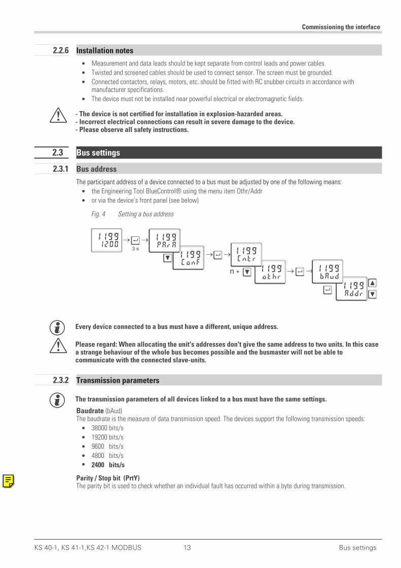
The participant address of a device connected to a bus must be adjusted by one of the following means:
• the Engineering Tool BlueControl® using the menu item Othr/Addr
• or via the device’s front panel (see below)
g Every device connected to a bus must have a different, unique address.
a Please regard: When allocating the unit's addresses don't give the same address to two units. In this casea strange behaviour of the whole bus becomes possible and the busmaster will not be able tocommunicate with the connected slave-units.
2.3.2 Transmission parameters
g The transmission parameters of all devices linked to a bus must have the same settings.
Baudrate (bAud)The baudrate is the measure of data transmission speed. The devices support the following transmission speeds:
• 38000 bits/s
• 19200 bits/s
• 9600 bits/s
• 4800 bits/s
• 2400 bits/s
Parity / Stop bit (PrtY)The parity bit is used to check whether an individual fault has occurred within a byte during transmission.
Commissioning the interface
KS 40-1, KS 41-1,KS 42-1 MODBUS 13 Bus settings
ConF
othr
Addr
1199
1199
1199
Ù
Ù
Ù
Ù
Ì
Ì
ÌÌ
3 s
n *
12001199
PArA
Cntr
bAud
1199
1199
1199
Fig. 4 Setting a bus address

The device supports:
• even parity
• odd parity
• no parity
With even parity, the parity bit is adjusted so that the sum of the set bits in the 8 data bits and the parity bit result inan even number. Conversely, the same applies for uneven parity.
g If a parity error is detected upon receipt of a message, the receiving device will not generate an answer.
Other parameters are:
• 8 data bits
• 1 start bit
• 1 stop bit1 or 2 stop bits can be selected when adjusting ‘no parity’.
g The max. length of a message may not exceed 256 bytes.
Commissioning the interface
Bus settings 14 KS 40-1, KS 41-1,KS 42-1 MODBUS
2.4 System layout
g Please observe the guidelines and notes provided by the manufacturer of the master device regarding thelayout of a communication system.
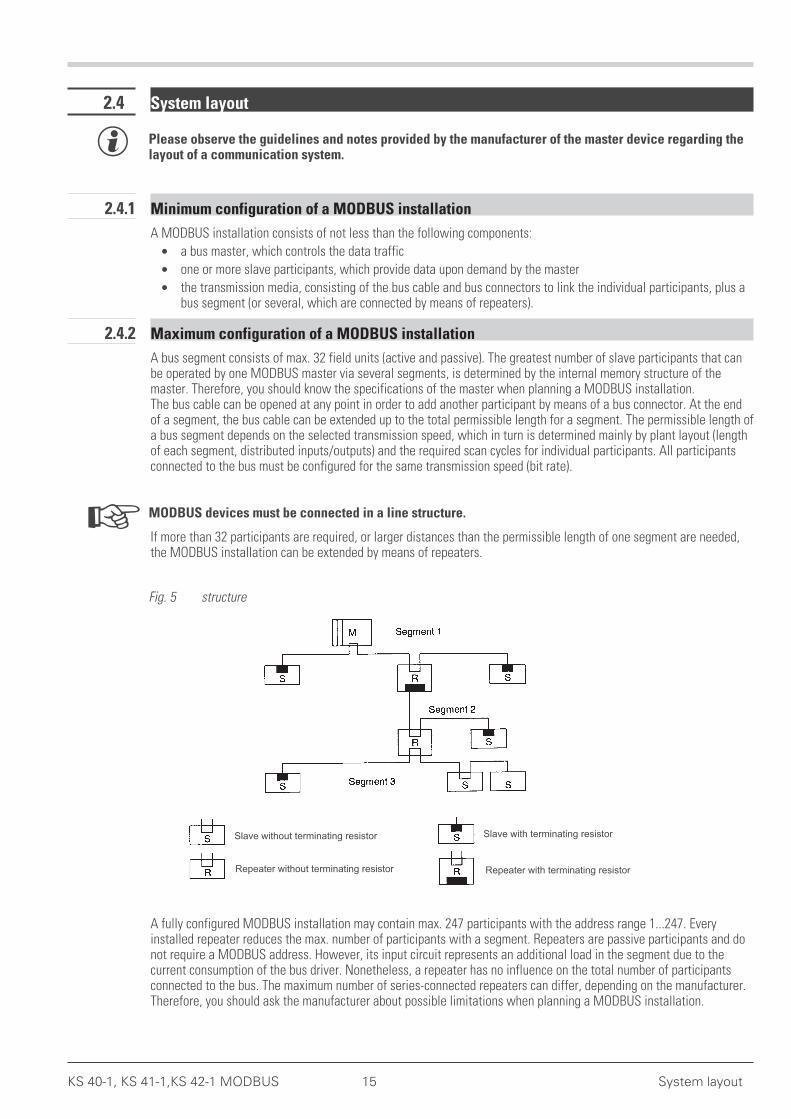
2.4.1 Minimum configuration of a MODBUS installation
A MODBUS installation consists of not less than the following components:
• a bus master, which controls the data traffic
• one or more slave participants, which provide data upon demand by the master
• the transmission media, consisting of the bus cable and bus connectors to link the individual participants, plus abus segment (or several, which are connected by means of repeaters).
2.4.2 Maximum configuration of a MODBUS installation
A bus segment consists of max. 32 field units (active and passive). The greatest number of slave participants that canbe operated by one MODBUS master via several segments, is determined by the internal memory structure of themaster. Therefore, you should know the specifications of the master when planning a MODBUS installation.The bus cable can be opened at any point in order to add another participant by means of a bus connector. At the endof a segment, the bus cable can be extended up to the total permissible length for a segment. The permissible length ofa bus segment depends on the selected transmission speed, which in turn is determined mainly by plant layout (lengthof each segment, distributed inputs/outputs) and the required scan cycles for individual participants. All participantsconnected to the bus must be configured for the same transmission speed (bit rate).
+ MODBUS devices must be connected in a line structure.
If more than 32 participants are required, or larger distances than the permissible length of one segment are needed,the MODBUS installation can be extended by means of repeaters.
A fully configured MODBUS installation may contain max. 247 participants with the address range 1...247. Everyinstalled repeater reduces the max. number of participants with a segment. Repeaters are passive participants and donot require a MODBUS address. However, its input circuit represents an additional load in the segment due to thecurrent consumption of the bus driver. Nonetheless, a repeater has no influence on the total number of participantsconnected to the bus. The maximum number of series-connected repeaters can differ, depending on the manufacturer.Therefore, you should ask the manufacturer about possible limitations when planning a MODBUS installation.
KS 40-1, KS 41-1,KS 42-1 MODBUS 15 System layout
Slave without terminating resistor
Repeater without terminating resistor Repeater with terminating resistor
Slave with terminating resistor
Fig. 5 structure
2.4.3 Wiring inside buildings
The following wiring hints apply for twisted-pair cables with screen. The cable screen serves to improve overallelectromagnetic compatibility.
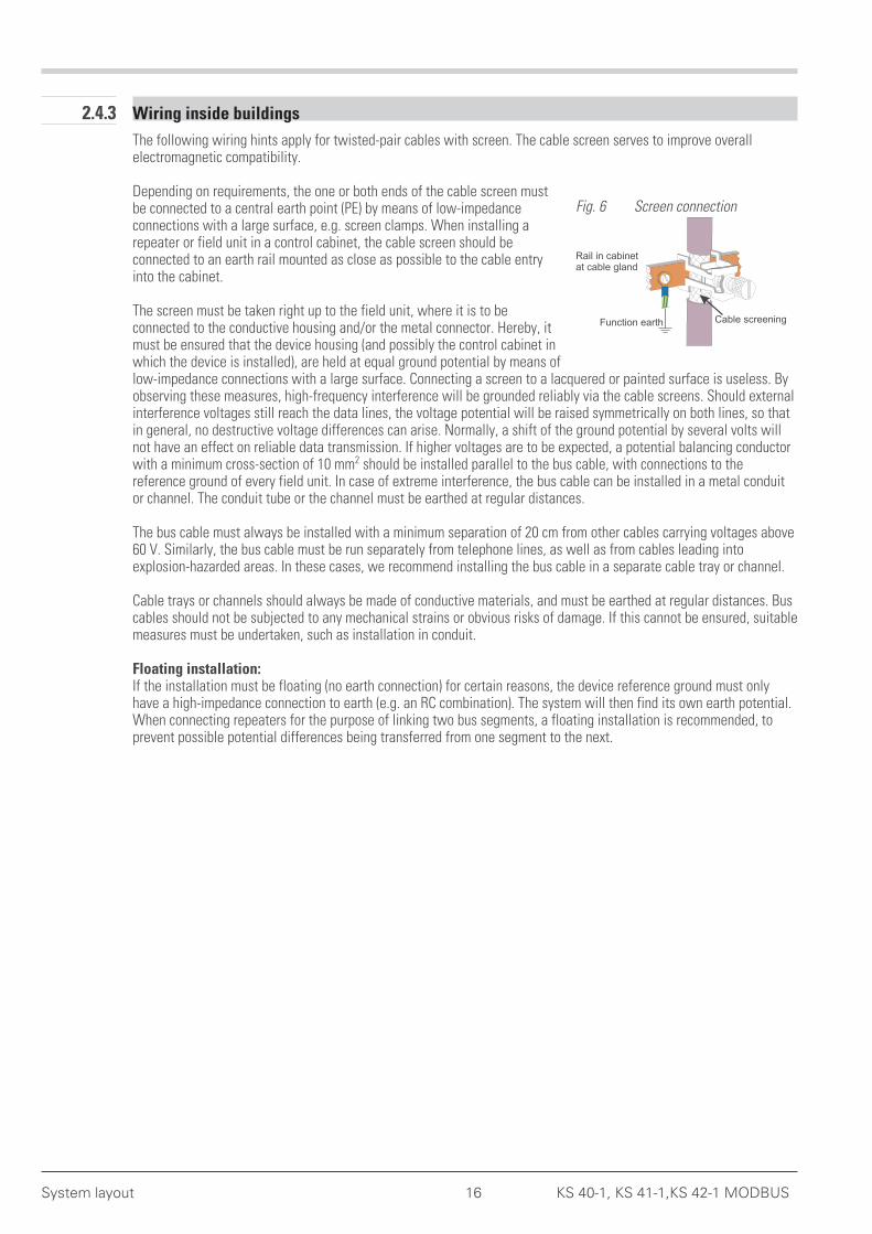
Depending on requirements, the one or both ends of the cable screen mustbe connected to a central earth point (PE) by means of low-impedanceconnections with a large surface, e.g. screen clamps. When installing arepeater or field unit in a control cabinet, the cable screen should beconnected to an earth rail mounted as close as possible to the cable entryinto the cabinet.
The screen must be taken right up to the field unit, where it is to beconnected to the conductive housing and/or the metal connector. Hereby, itmust be ensured that the device housing (and possibly the control cabinet inwhich the device is installed), are held at equal ground potential by means oflow-impedance connections with a large surface. Connecting a screen to a lacquered or painted surface is useless. Byobserving these measures, high-frequency interference will be grounded reliably via the cable screens. Should externalinterference voltages still reach the data lines, the voltage potential will be raised symmetrically on both lines, so thatin general, no destructive voltage differences can arise. Normally, a shift of the ground potential by several volts willnot have an effect on reliable data transmission. If higher voltages are to be expected, a potential balancing conductorwith a minimum cross-section of 10 mm2 should be installed parallel to the bus cable, with connections to thereference ground of every field unit. In case of extreme interference, the bus cable can be installed in a metal conduitor channel. The conduit tube or the channel must be earthed at regular distances.
The bus cable must always be installed with a minimum separation of 20 cm from other cables carrying voltages above60 V. Similarly, the bus cable must be run separately from telephone lines, as well as from cables leading intoexplosion-hazarded areas. In these cases, we recommend installing the bus cable in a separate cable tray or channel.
Cable trays or channels should always be made of conductive materials, and must be earthed at regular distances. Buscables should not be subjected to any mechanical strains or obvious risks of damage. If this cannot be ensured, suitablemeasures must be undertaken, such as installation in conduit.
Floating installation:If the installation must be floating (no earth connection) for certain reasons, the device reference ground must onlyhave a high-impedance connection to earth (e.g. an RC combination). The system will then find its own earth potential.When connecting repeaters for the purpose of linking two bus segments, a floating installation is recommended, toprevent possible potential differences being transferred from one segment to the next.
System layout 16 KS 40-1, KS 41-1,KS 42-1 MODBUS
Rail in cabinetat cable gland
Function earth Cable screening
Fig. 6 Screen connection
. 3 Bus protocol
3.1 Composition of a transmission byte
Originally, the MODBUS protocol was defined for the communication between a supervisory system and the ModiconPLC. It used a master/slave structure, in which only one device (master) is able to initiate data transactions (queries).The query message from the master is answered (response) by other devices (slaves), which supply the requested data.Moreover, the master can address a specific slave via its MODBUS address, or address all connected slaves by meansof a general message (broadcast).The MODBUS protocol determines the transmission formats for the query and the response. Function codes define theactions to be executed by the slaves.Within the device, the MODBUS protocol uses the RTU (remote terminal unit) mode, i.e. every transmitted byte of amessage contains two hexadecimal characters (0...9, A...F).
The composition of a byte in the RTU-protocol is as follows:
Start bit 8 data bits Parity/Stop bit Stop bit
3.2 General message frame
The message is read into a data buffer with a defined maximum length. Longer messages are not accepted, i.e. thedevice does not answer.
The message consist of the following elements:
Device address Function code Data field CRC End of frame detection1 byte 1 byte N * 1 bytes 2 bytes
• Device address (Addr)The device address is used for identification. Device addresses can be assigned in the range of 1...127.The device address ‘0’ is reserved for ‘Broadcast’ messages to all slaves. A broadcast message can betransmitted e.g. with a write instruction that is then executed by all the slaves on the bus. Because all the slavesexecute the instruction, no response messages are generated.
• Function codeThe function code defines the transaction type in a message. The MODBUS specification defines more than 17different function codes. Supported codes are described in Section 3.6. „Function codes“.
• Data fieldThe data field contains the detailed specifications of the transaction defined by the function code. The length ofthe data field depends on the function code.
• CRCAs a further means of fault detection (in addition to parity bit detection) a 16-bit cyclical redundancy check (CRC)is performed. The CRC code ensures that communication errors are detected. For additional information, seeSection 3.2.1. ”CRC”.
• End of frame detectionThe end of a message is defined by a period of 3,5 characters, during which no data transfer occurs. Foradditional information, see Section 3.2.2. „End of frame detection“
g Further information is given in the documents named in [1] or under http://www.modbus.org.
Bus protocol
KS 40-1, KS 41-1,KS 42-1 MODBUS 17 Composition of a transmission byte
3.2.1 CRC
The CRC is a 16-bit value that is attached to the message. It serves to determine whether a transmitted message hasbeen received without errors. Together with the parity check, this should detect all possible communication errors.
g If a parity fault is detected during reading, no response message will be generated.
The algorithm for generating a CRC is as follows:
Load CRC register with FFFFhex.
Exclusive OR the first transmit/receive byte with the low-order byte of the CRC register,putting the result into the CRC register, zero-filling the MSB.
Shift the CRC register one bit to the right.
If the expelled bit is a '0' repeat step 3.If the expelled bit is a ‘1’, exclusive OR the CRC register with value A001hex.
Repeat steps 3 and 4 for the other 7 data bits.
Repeat steps 2 to 5 for all further transmit/receive bytes.
Attach the result of the CRC register to the message (low-order byte first, then the high-order byte).When checking a received message, the CRC register will return ‘0’, when the message including the CRC isprocessed.
3.2.2 End of frame detection
The end of a message (frame) is defined as a silence period of 3.5 characters on the MODBUS.A slave may not start its response, and a master may not start a new transmission before this time has elapsed.
However, the evaluation of a message may begin, if a silence period of more than 1.5 characters occurs on theMODBUS. But the response may not start before 3,5 characters of silence.
3.3 Transmission principles
Two transmission modes are used with MODBUS:
• Unicast mode
• Broadcast mode
In the Unicast mode, the master addresses an individual device, which processes the received message and generatesa response. The device address can be 1...247. Messages always consist of a query (request) and an answer(response). If no response is read within a defined time, a timeout error is generated.
In the Broadcast mode, the master sends a write instruction (request) to all participants on the bus, but no responsesare generated. The address ‘0’ is reserved for broadcast messages.
3.4 Response delay (dELY)
Some devices require a certain period to switch from transmit to receive. The adjusted delay is added to the silentperiod of 3,5 characters at the end of a message, before a response is generated. The delay is set in ms.
3.5 Modem operation (C.dEL)
The end of frame detection of a received MODBUS message can be increased by the period ‘C.del’. This time isneeded e.g. for transmission via a modem, if messages cannot be transmitted continuously (synchronous operation).The delay is set in ms.
Bus protocol
Transmission principles 18 KS 40-1, KS 41-1,KS 42-1 MODBUS

3.6 Function codes
Function codes serve to execute instructions. The device supports the following function codes:
Function code Description Explanation
hex dez
0x03 3 Read Holding (Output) Register Reading of process data, parameters, and configuration data
0x04 4 Read Input Register Reading of process data, parameters, and configuration data
0x06 6 Preset Single Register (Output) Wordwise writing of a value (process value, parameter, orconfiguration data)
0x08 8 Diagnostics Reading the MODBUS diagnostic register
0x10 16 Preset Multiple Register (Output) Wordwise writing of several values (process data, parameter orconfiguration data)
The behaviour of function codes 3 and 4 is identical.The following sections show various examples of message composition.
3.6.1 Reading several values
Messages with function codes 3 or 4 are used for (wordwise) reading of process data, parameters or configurationdata. For reading ‘Float’ type data, 2 values must be requested for each datum.
The composition of a read message is as follows:Request:
Field name Value (hex) Explanation
Address 11 Address 17
Function 03 or 04 Reading process data, parameters or configuration data
Start address HighStart address Low
028A
Starting address 650
No. of values 0002
2 datums (2 words)
CRC CRC-Byte1CRC-Byte2
Response:
Field name Value (hex) Explanation
Address 11 Address 17
Function 03 oder 04 Reading process data, parameters or configuration data
No. of bytes 04 4 data bytes are transmitted
Word 1 00DE
Process data, parameters or configuration data.Address 650= 222
Word 2 014D
Process data, parameters or configuration data.Address 651= 333
CRC CRC-byte1CRC-byte2
g A broadcast message is not possible for function codes 3 and 4.
g If the first addressed value is not defined, an error message ”ILLEGAL DATA ADDRESS” is generated.If no further data are defined in the areas to be read following the first value, these areas will be enteredwith the value ”NOT DEFINED VALUE”. This enables areas with gaps to be to be read in a message.
Bus protocol
KS 40-1, KS 41-1,KS 42-1 MODBUS 19 Function codes
3.6.2 Writing a single value
Messages with function code 6 are used for (wordwise) writing of process data, parameters or configuration data asintegers. This function is not suitable for writing ‘Float’ type data.
The composition of a write message is as follows:Request:
Field name Value (hex) Explanation
Address 11 Address 17
Function 06 Writing a single value (process data, parameter or configuration)
Write address HighWrite address Low
028A
Write address 650
Value 007B
Preset value = 123
CRC CRC-byte1CRC-byte2
Response:
Field name Value (hex) Explanation
Address 11 Address 17
Function 06 Writing a single datum (process data, parameter or configuration)
Write address HighWrite address Low
028A
Write address 650
Value 007B
Preset value = 123
CRC CRC-Byte1CRC-Byte2
If everything is correct, the response message corresponds exactly to the default.
g The devices can also receive this message as a broadcast with the address ‘0’.
g A default value in the ‘Real’ data format is not possible, as only 2 bytes can be transmitted as value.
g If a value is outside the adjustable range, the error message ”ILLEGAL DATA VALUE” is generated. Thedatum remains unchanged. Also if the datum cannot be written (e.g. configuration data, and the device isonline), an error message ”ILLEGAL DATA VALUE” is generated.
Bus protocol
Function codes 20 KS 40-1, KS 41-1,KS 42-1 MODBUS
3.7 Writing several values
Messages with function code 16 are used for (wordwise) writing of process data, parameters or configuration data. Forwriting ‘Float’ type data, 2 values must be transmitted for each datum.
The composition of a write message is as follows:Request:
Field name Value (hex) ExplanationAddress 11 Address 17Function 10 Writing several process values, parameters or configuration dataStart address HighStart address Low
028A
Write address 650
No. of values 0002
2 values
No. of bytes 04 4 data bytes are transmittedWord 1 00
DEProcess value, parameters or configuration data.Address 650 = 222
Word 2 014D
Process value, parameters or configuration data.Address 651 = 333
CRC CRC byte1CRC byte2
Response:
Field name Value (hex) ExplanationAddress 11 Address 17Function 10 Writing several process values, parameters or configuration dataStart address HighStart address Low
028A
Write address 650
No. of values 0002
2 process values, parameters or configuration data
CRC CRC byte1CRC byte2
g The devices can also receive this message as a broadcast with the address ‘0’.
g If the first value is not defined, an error message ”ILLEGAL DATA ADDRESS” is generated.If the first value cannot be written (e.g. configuration data, and the device is online), an error message”ILLEGAL DATA VALUE” is generated.
If no further data are defined or cannot be written in the specified areas following the first value, these areas will beskipped. The data in these locations remains unchanged. This enables areas with gaps, or that are currently notwritable, to be changed with a message. No error message is generated.
If a value is outside the adjustable range, the error message ”ILLEGAL DATA VALUE” is generated. Subsequent dataare not evaluated. Previously accepted correct data are active.
Bus protocol
KS 40-1, KS 41-1,KS 42-1 MODBUS 21 Writing several values
3.8 Error record
An error record is generated, if a message is received correctly, but message interpretation or the modification of adatum is not possible.
g If a transmission error is detected, no response is generated. The master must retransmit the message.
Detected transmission errors are:
• Parity fault
• Framing error (no stop bit received)
• Overrun error (receiving buffer has overflowed or data could not be retrieved quickly enough from the UART)
• CRC error
The composition of the error record is as follows:
Field name Value ExplanationAddress 11 Address 17Function 90 Error record for the message ‘Writing several parameters or configuration data’.
Composition: 80hex + function codeError code 02 ILLEGAL DATA ADDRESSCRC CRC byte1
CRC byte2
In the ‘Function’ field, the most significant bit is set.The error code is transmitted in the subsequent byte.
3.8.1 Error codes
The following error codes are defined:
Code Name Explanation01 ILLEGAL FUNCTION The received function code is not defined in the device.02 ILLEGAL DATA ADDRESS The received address is not defined in the device, or the value may not be
written (read only).If several data are read simultaneously (function codes 01, 03, 04) orwritten simultaneously (function codes 0F, 10), this error is only generatedif the first datum is not defined.
03 ILLEGAL DATA VALUE The received value is outside the adjusted limits or it cannot be written atpresent (device is not in the configuration mode).If several data are written simultaneously (function codes 0F, 10), thiserror is only generated if the first datum cannot be written.
04 SLAVE DEVICE FAILURE More values are requested than permitted by the transmission buffer.
Other error codes specified in the MODBUS protocol are not supported.
Bus protocol
Error record 22 KS 40-1, KS 41-1,KS 42-1 MODBUS

3.9 Diagnosis
By means of the diagnosis message, the device can be prompted to send check messages, go into operational states,output counter values or to reset the counters.This message can never be sent as a broadcast message.
The following functions have been defined:
Code Explanation0x00 Return transmission of the received message0x01 Restart of communication (terminates the Listen Only mode)0x02 Return transmission of the diagnosis register0x04 Change to the Listen Only mode0x0A Delete the counter and reset the diagnosis register0x0B Return transmission of the message counter (all messages on the bus)0x0C Reset of the counter for faulty message transmissions to this slave (parity or CRC error)0x0D Return transmission of the counter for messages answered with error code0x0E Return transmission of the message counter for this slave0x0F Return transmission of the counter for unanswered messages0x10 Return transmission of the counter for messages answered with NAK0x11 Return transmission of the counter for messages answered with Busy0x12 Return transmission of the counter for too long messages0x40 Return transmission of the parity error counter0x41 Return transmission of the framing error counter (stop bit not detected)0x42 Return transmission of the counter for full buffer (message longer than receiving buffer)
Request in the Integer format:If the setting for Integer with decimals (most significant 3 bits) is used for the address, the counter contents willbe transmitted in accordance with the necessary conversion factor.
Request in the Float format:If the setting for Float (most significant 3 bits are 010) is used for the address, the counter contents will betransmitted in the IEEE format. The largest value is 65535, because the counters in the device are designed asword counters.In the Float format, a 4-byte data field is returned with a request for counter contents. In all other cases, a 2-bytedata field is returned.
When switching into the Listen mode (0x04) and at restart after the device has changed into the Listen mode, noresponse is generated.If a restart diagnosis message is received while the device is not in the Listen mode, the device generates a response.
A diagnosis message is composed as follows:
Request:
Field name Value ExplanationAddress 11 Address 17Function 08 Diagnosis messageSub-function HighSub-function Low
00YY
Sub-function code
Data field Byte 1Byte 2
Further data definitions
CRC CRC byte1CRC byte2
Bus protocol
KS 40-1, KS 41-1,KS 42-1 MODBUS 23 Diagnosis
3.9.1 Return transmission of the received message (0x00)
The message serves as a check whether communication is operational.Definition of the received and returned data:
Sub-function Received data field Transmitted data field00 00 2 bytes of any content Return transmission of the received datum
3.9.2 Restart of communication (terminates the Listen Only mode) (0x01)
The slave is instructed to initialize its interface, and to delete the event counters. In addition, the device is instructed toexit the Listen Only mode. If the device already is in the Listen Only mode, no response is generated.Definition of the received and returned data:
Sub-function Received data field Transmitted data field00 01 00 00 00 00
3.9.3 Return transmission of the diagnosis register (0x02)
The slave sends its 16-bit diagnosis register to the master. The data contained in this register are freely definable. Forexample, the information could be: EEPROM faulty, LED defective, etc.Definition of the received and returned data:
Sub-function Received data field Transmitted data field00 02 00 00 Contents of the diagnosis register
3.9.4 Change to the Listen Only mode (0x04)
The slave is instructed not to execute or answer any messages addressed to it. The device can only return to normaloperation by means of the diagnosis message ‘Sub-function 00 01’ or by means of a new power up.
The function serves to disable a module that is behaving erratically on the MODBUS, so that the bus can continueoperations. The device does not generate a response after receiving this message.Definition of the received and returned data:
Sub-function Received data field Transmitted data field00 04 00 00 No response
3.9.5 Delete the counter and reset the diagnosis register (0x0A)
The slave is instructed to delete the contents of its event counter and to reset the diagnosis register.Definition of the received and returned data:
Sub-function Received data field Transmitted data field00 0A 00 00 00 00
Bus protocol
Diagnosis 24 KS 40-1, KS 41-1,KS 42-1 MODBUS
3.9.6 Return transmission of the message counter (0x0B)
The slave is instructed to return the value of its message counter.The counter contains the sum of all messages, which the slave has recorded on the bus. This count includes all themessages transmitted by the master and the other slaves. The count does not include the response messages of thisslave.Definition of the received and returned data:
Sub-function Received data field Transmitted data field00 0B 00 00 Message counter
3.9.7 Return transmission of the counter for faulty message transmissions (0x0C)
The slave is instructed to return the value of its counter for faulty message transmissions.The counter contains the sum of all messages addressed to the slave, in which an error was detected. Hereby, thefaults can be CRC or parity errors.Definition of the received and returned data:
Sub-function Received data field Transmitted data field00 0C 00 00 Contents of counter for faulty message transmissions
3.9.8 Return transmission of the counter for messages answered with error code (0x0D)
The slave is instructed to return the value of its counter for the messages answered with error code. The countercontains the sum of all messages addressed to the slave, and which were answered with an error code.Definition of the received and returned data:
Sub-function Received data field Transmitted data field00 0D 00 00 Contents of counter for messages answered with an error code
3.9.9 Return transmission of the message counter for this slave (0x0E)
The slave is instructed to return the value of its counter for messages to this slave.The counter contains the sum of all messages addressed to the slave.Definition of the received and returned data:
Sub-function Received data field Transmitted data field00 0E 00 00 Contents of counter for messages addressed to this slave
3.9.10 Return transmission of the counter for unanswered messages (0x0F)
The slave is instructed to return the value of its counter for unanswered messages.The counter contains the sum of all messages addressed to the slave, which were not answered because of internalevents or detected errors.Definition of the received and returned data:
Sub-function Received data field Transmitted data field00 0F 00 00 Contents of counter for unanswered messages
Bus protocol
KS 40-1, KS 41-1,KS 42-1 MODBUS 25 Diagnosis

3.9.11 Return transmission of the counter for messages answered with NAK (0x10)
The slave is instructed to return the value of its counter for messages answered with NAK.The counter contains the sum of all messages addressed to the slave, which were answered with NAK.Definition of the received and returned data:
Sub-function Received data field Transmitted data field00 10 00 00 Contents of counter for messages answered with NAK
3.9.12 Return transmission of the counter for messages answered with Busy (0x11)
The slave is instructed to return the value of its counter for messages answered with Busy.The counter contains the sum of all messages addressed to the slave, which were answered with Busy.Definition of the received and returned data:
Sub-function Received data field Transmitted data field00 12 00 00 Contents of counter for messages answered with Busy
3.9.13 Return transmission of the parity error counter (0x40)
The slave is instructed to return the value of its counter for parity errors.The counter contains the sum of all messages addressed to the slave, in which a parity error was detected.Definition of the received and returned data:
Sub-function Received data field Transmitted data field00 40 00 00 Contents of counter for the number of parity errors
3.9.14 Return transmission of the framing error counter (0x41)
The slave is instructed to return the value of its counter for the number of framing errors.The counter contains the sum of all messages addressed to the slave, in which a framing error was detected. A framingerror occurs, if the stop bit at the end of a byte is not detected.Definition of the received and returned data:
Sub-function Received data field Transmitted data field00 41 00 00 Contents of counter for the number of framing errors
3.9.15 Return transmission of the counter for too long messages (0x12)
The slave is instructed to return the value of its counter for too long messages.The counter contains the sum of all messages addressed to the slave, which caused an overflow of the receivingbuffer, or if the data were not retrieved from the UART quickly enough.Definition of the received and returned data:
Sub-function Received data field Transmitted data field00 42 00 00 Counter for too long messages
Bus protocol
Diagnosis 26 KS 40-1, KS 41-1,KS 42-1 MODBUS
. 4 MODBUS addresses, address areas, and address formats
4.1 Area definitions
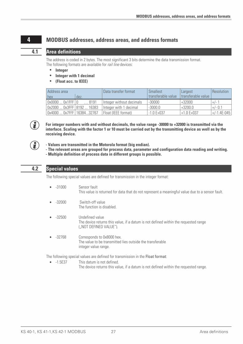
The address is coded in 2 bytes. The most significant 3 bits determine the data transmission format.The following formats are available for rail line devices:
• Integer
• Integer with 1 decimal
• (Float acc. to IEEE)
Address area Data transfer format Smallesttransferable value
Largesttransferable value
Resolutionhex dez.0x0000 ... 0x1FFF 0 … 8191 Integer without decimals -30000 +32000 +/- 10x2000 ... 0x3FFF 8192 ... 16383 Integer with 1 decimal -3000.0 +3200.0 +/- 0.10x4000 ... 0x7FFF 16384...32767 Float (IEEE format) -1.0 E+037 +1.0 E+037 +/-1.4E-045
g For integer numbers with and without decimals, the value range -30000 to +32000 is transmitted via theinterface. Scaling with the factor 1 or 10 must be carried out by the transmitting device as well as by thereceiving device.
g - Values are transmitted in the Motorola format (big endian).- The relevant areas are grouped for process data, parameter and configuration data reading and writing.- Multiple definition of process data in different groups is possible.
4.2 Special values
The following special values are defined for transmission in the integer format:
• -31000 Sensor faultThis value is returned for data that do not represent a meaningful value due to a sensor fault.
• -32000 Switch-off valueThe function is disabled.
• -32500 Undefined valueThe device returns this value, if a datum is not defined within the requested range(„NOT DEFINED VALUE“).
• -32768 Corresponds to 0x8000 hex.The value to be transmitted lies outside the transferableinteger value range.
The following special values are defined for transmission in the Float format:
• -1.5E37 This datum is not defined.The device returns this value, if a datum is not defined within the requested range.
MODBUS addresses, address areas, and address formats
KS 40-1, KS 41-1,KS 42-1 MODBUS 27 Area definitions
4.3 Composition of the address tables
In the address tables shown in Section 5, the addresses for every parameter of the corresponding data format arespecified in decimal values.The tables are structured as follows:
Name R/W Address Integer Real Type Value/off Descriptionbase1dP
– Name Description of the datum– R/W permitted type of access: R = read, W = write– Address integer Address for integer values– base Integer without decimals– 1 dP Integer with 1 decimal– Real Floating point number / Float (IEEE format)– Type internal data type– Value/off permissible value range, switch-off value available– Description Explanations
4.4 Internal data types
The following data types are assigned to data used in the device:
• FloatFloating point numberValue range: -1999 ... -0.001, 0, 0.001 ... 9999
• INTPositive whole integer numberValue range: 0 ... 65535Exception: Switch-off value ‘-32000’
• TextText string consisting of n characters, currently defined n = 5Permissible characters: 20H...7FH
• LongPositive whole Long numberValue range: 0 … 99999
• EnumSelection value
MODBUS addresses, address areas, and address formats
Composition of the address tables 28 KS 40-1, KS 41-1,KS 42-1 MODBUS
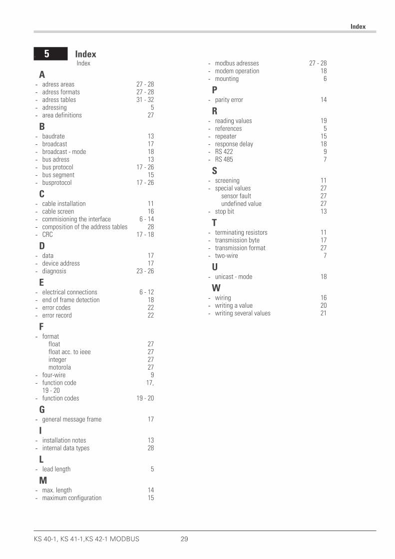
. 5 Index
Index
KS 40-1, KS 41-1,KS 42-1 MODBUS 29
Index
A- adress areas 27 - 28- adress formats 27 - 28- adress tables 31 - 32- adressing 5- area definitions 27
B- baudrate 13- broadcast 17- broadcast - mode 18- bus adress 13- bus protocol 17 - 26- bus segment 15- busprotocol 17 - 26
C- cable installation 11- cable screen 16- commisioning the interface 6 - 14- composition of the address tables 28- CRC 17 - 18
D- data 17- device address 17- diagnosis 23 - 26
E- electrical connections 6 - 12- end of frame detection 18- error codes 22- error record 22
F- format
float 27float acc. to ieee 27integer 27motorola 27
- four-wire 9- function code 17,
19 - 20- function codes 19 - 20
G- general message frame 17
I- installation notes 13- internal data types 28
L- lead length 5
M- max. length 14- maximum configuration 15
- modbus adresses 27 - 28- modem operation 18- mounting 6
P- parity error 14
R- reading values 19- references 5- repeater 15- response delay 18- RS 422 9- RS 485 7
S- screening 11- special values 27
sensor fault 27undefined value 27
- stop bit 13
T- terminating resistors 11- transmission byte 17- transmission format 27- two-wire 7
U- unicast - mode 18
W- wiring 16- writing a value 20- writing several values 21

Index
30 iKS 40-1, KS 41-1,KS 42-1 MODBUS

. 6 Address tables
The following sections describe the address tables for:
• Industrial controller KS 40-1, valid also for KS 41-1 and KS 42-1
Address tables
KS 40-1, KS 41-1,KS 42-1 MODBUS 31

Address tables
32 KS 40-1, KS 41-1,KS 42-1 MODBUS
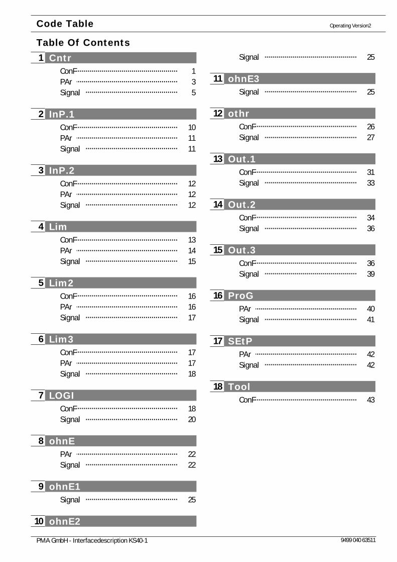
Cntr 1ConF 1PAr 3Signal 5
InP.1 2ConF 10PAr 11Signal 11
InP.2 3ConF 12PAr 12Signal 12
Lim 4ConF 13PAr 14Signal 15
Lim2 5ConF 16PAr 16Signal 17
Lim3 6ConF 17PAr 17Signal 18
LOGI 7ConF 18Signal 20
ohnE 8PAr 22Signal 22
ohnE1 9Signal 25
ohnE210
Signal 25
ohnE311Signal 25
othr12ConF 26Signal 27
Out.113ConF 31Signal 33
Out.214ConF 34Signal 36
Out.315ConF 36Signal 39
ProG16PAr 40Signal 41
SEtP17PAr 42Signal 42
Tool18ConF 43
Operating Version2
Table Of ContentsCode Table
PMA GmbH - Interfacedescription KS40-1 9499 040 63511

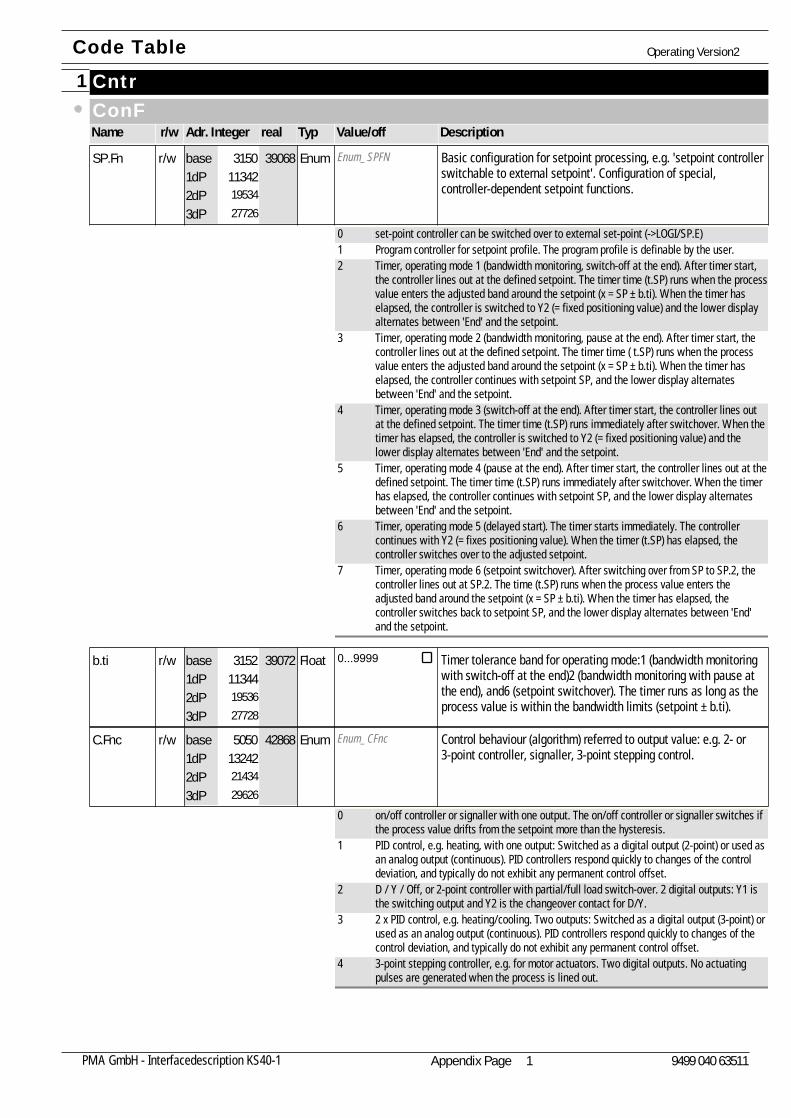
Cntr1ConFName Adr. Integer realr/w Typ Value/off Description
Enum_SPFN Basic configuration for setpoint processing, e.g. 'setpoint controllerswitchable to external setpoint'. Configuration of special,controller-dependent setpoint functions.
SP.Fn113421953427726
39068r/w Enum3150base1dP2dP3dP
0 set-point controller can be switched over to external set-point (->LOGI/SP.E)1 Program controller for setpoint profile. The program profile is definable by the user.2 Timer, operating mode 1 (bandwidth monitoring, switch-off at the end). After timer start,
the controller lines out at the defined setpoint. The timer time (t.SP) runs when the processvalue enters the adjusted band around the setpoint (x = SP ± b.ti). When the timer haselapsed, the controller is switched to Y2 (= fixed positioning value) and the lower displayalternates between 'End' and the setpoint.
3 Timer, operating mode 2 (bandwidth monitoring, pause at the end). After timer start, thecontroller lines out at the defined setpoint. The timer time ( t.SP) runs when the processvalue enters the adjusted band around the setpoint (x = SP ± b.ti). When the timer haselapsed, the controller continues with setpoint SP, and the lower display alternatesbetween 'End' and the setpoint.
4 Timer, operating mode 3 (switch-off at the end). After timer start, the controller lines outat the defined setpoint. The timer time (t.SP) runs immediately after switchover. When thetimer has elapsed, the controller is switched to Y2 (= fixed positioning value) and thelower display alternates between 'End' and the setpoint.
5 Timer, operating mode 4 (pause at the end). After timer start, the controller lines out at thedefined setpoint. The timer time (t.SP) runs immediately after switchover. When the timerhas elapsed, the controller continues with setpoint SP, and the lower display alternatesbetween 'End' and the setpoint.
6 Timer, operating mode 5 (delayed start). The timer starts immediately. The controllercontinues with Y2 (= fixes positioning value). When the timer (t.SP) has elapsed, thecontroller switches over to the adjusted setpoint.
7 Timer, operating mode 6 (setpoint switchover). After switching over from SP to SP.2, thecontroller lines out at SP.2. The time (t.SP) runs when the process value enters theadjusted band around the setpoint (x = SP ± b.ti). When the timer has elapsed, thecontroller switches back to setpoint SP, and the lower display alternates between 'End'and the setpoint.
Timer tolerance band for operating mode:1 (bandwidth monitoringwith switch-off at the end)2 (bandwidth monitoring with pause atthe end), and6 (setpoint switchover). The timer runs as long as theprocess value is within the bandwidth limits (setpoint ± b.ti).
b.ti113441953627728
39072r/w Float 0...99993152base1dP2dP3dP
Enum_CFnc Control behaviour (algorithm) referred to output value: e.g. 2- or3-point controller, signaller, 3-point stepping control.
C.Fnc132422143429626
42868r/w Enum5050base1dP2dP3dP
0 on/off controller or signaller with one output. The on/off controller or signaller switches ifthe process value drifts from the setpoint more than the hysteresis.
1 PID control, e.g. heating, with one output: Switched as a digital output (2-point) or used asan analog output (continuous). PID controllers respond quickly to changes of the controldeviation, and typically do not exhibit any permanent control offset.
2 D / Y / Off, or 2-point controller with partial/full load switch-over. 2 digital outputs: Y1 isthe switching output and Y2 is the changeover contact for D/Y.
3 2 x PID control, e.g. heating/cooling. Two outputs: Switched as a digital output (3-point) orused as an analog output (continuous). PID controllers respond quickly to changes of thecontrol deviation, and typically do not exhibit any permanent control offset.
4 3-point stepping controller, e.g. for motor actuators. Two digital outputs. No actuatingpulses are generated when the process is lined out.
Code Table Operating Version2
Appendix Page 1PMA GmbH - Interfacedescription KS40-1 9499 040 63511
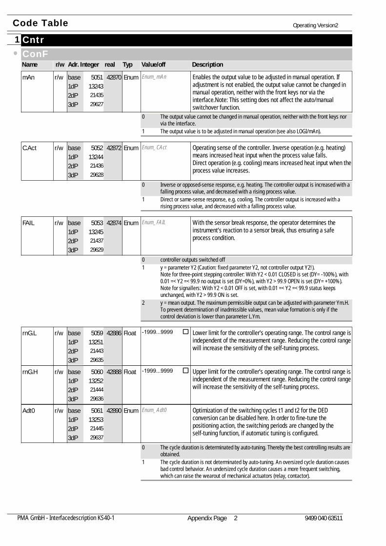
Cntr1ConFName Adr. Integer realr/w Typ Value/off Description
Enum_mAn Enables the output value to be adjusted in manual operation. Ifadjustment is not enabled, the output value cannot be changed inmanual operation, neither with the front keys nor via theinterface.Note: This setting does not affect the auto/manualswitchover function.
mAn132432143529627
42870r/w Enum5051base1dP2dP3dP
0 The output value cannot be changed in manual operation, neither with the front keys norvia the interface.
1 The output value is to be adjusted in manual operation (see also LOGI/mAn).
Enum_CAct Operating sense of the controller. Inverse operation (e.g. heating)means increased heat input when the process value falls.Direct operation (e.g. cooling) means increased heat input when theprocess value increases.
C.Act132442143629628
42872r/w Enum5052base1dP2dP3dP
0 Inverse or opposed-sense response, e.g. heating. The controller output is increased with afalling process value, and decreased with a rising process value.
1 Direct or same-sense response, e.g. cooling. The controller output is increased with arising process value, and decreased with a falling process value.
Enum_FAIL With the sensor break response, the operator determines theinstrument's reaction to a sensor break, thus ensuring a safeprocess condition.
FAIL132452143729629
42874r/w Enum5053base1dP2dP3dP
0 controller outputs switched off1 y = parameter Y2 (Caution: fixed parameter Y2, not controller output Y2!).
Note for three-point stepping controller: With Y2 < 0.01 CLOSED is set (DY= -100%), with0.01 =< Y2 =< 99.9 no output is set (DY=0%), with Y2 > 99.9 OPEN is set (DY= +100%).Note for signallers: With Y2 < 0.01 OFF is set, with 0.01 =< Y2 =< 99.9 status keepsunchanged, with Y2 > 99.9 ON is set.
2 y = mean output. The maximum permissible output can be adjusted with parameter Ym.H.To prevent determination of inadmissible values, mean value formation is only if thecontrol deviation is lower than parameter L.Ym.
Lower limit for the controller's operating range. The control range isindependent of the measurement range. Reducing the control rangewill increase the sensitivity of the self-tuning process.
rnG.L132512144329635
42886r/w Float -1999...99995059base1dP2dP3dP
Upper limit for the controller's operating range. The control range isindependent of the measurement range. Reducing the control rangewill increase the sensitivity of the self-tuning process.
rnG.H132522144429636
42888r/w Float -1999...99995060base1dP2dP3dP
Enum_Adt0 Optimization of the switching cycles t1 and t2 for the DEDconversion can be disabled here. In order to fine-tune thepositioning action, the switching periods are changed by theself-tuning function, if automatic tuning is configured.
Adt0132532144529637
42890r/w Enum5061base1dP2dP3dP
0 The cycle duration is determinated by auto-tuning. Thereby the best controlling results areobtained.
1 The cycle duration is not determinated by auto-tuning. An oversized cycle duration causesbad control behavior. An undersized cycle duration causes a more frequent switching,which can raise the wearout of mechanical actuators (relay, contactor).
Code Table Operating Version2
Appendix Page 2PMA GmbH - Interfacedescription KS40-1 9499 040 63511
Cntr1PArAName Adr. Integer realr/w Typ Value/off Description
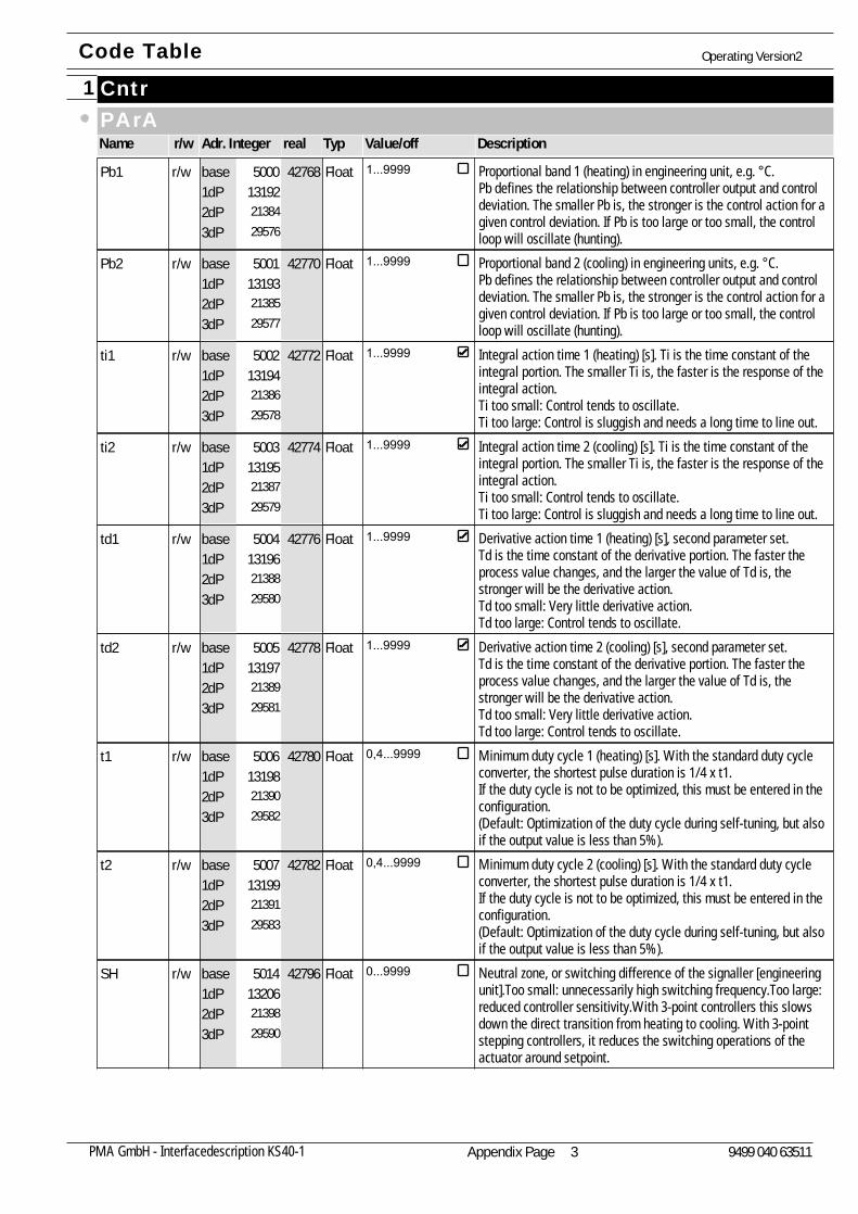
Proportional band 1 (heating) in engineering unit, e.g. °C.Pb defines the relationship between controller output and controldeviation. The smaller Pb is, the stronger is the control action for agiven control deviation. If Pb is too large or too small, the controlloop will oscillate (hunting).
Pb1131922138429576
42768r/w Float 1...99995000base1dP2dP3dP
Proportional band 2 (cooling) in engineering units, e.g. °C.Pb defines the relationship between controller output and controldeviation. The smaller Pb is, the stronger is the control action for agiven control deviation. If Pb is too large or too small, the controlloop will oscillate (hunting).
Pb2131932138529577
42770r/w Float 1...99995001base1dP2dP3dP
Integral action time 1 (heating) [s]. Ti is the time constant of theintegral portion. The smaller Ti is, the faster is the response of theintegral action.Ti too small: Control tends to oscillate.Ti too large: Control is sluggish and needs a long time to line out.
ti1131942138629578
42772r/w Float 1...99995002base1dP2dP3dP
Integral action time 2 (cooling) [s]. Ti is the time constant of theintegral portion. The smaller Ti is, the faster is the response of theintegral action.Ti too small: Control tends to oscillate.Ti too large: Control is sluggish and needs a long time to line out.
ti2131952138729579
42774r/w Float 1...99995003base1dP2dP3dP
Derivative action time 1 (heating) [s], second parameter set.Td is the time constant of the derivative portion. The faster theprocess value changes, and the larger the value of Td is, thestronger will be the derivative action.Td too small: Very little derivative action.Td too large: Control tends to oscillate.
td1131962138829580
42776r/w Float 1...99995004base1dP2dP3dP
Derivative action time 2 (cooling) [s], second parameter set.Td is the time constant of the derivative portion. The faster theprocess value changes, and the larger the value of Td is, thestronger will be the derivative action.Td too small: Very little derivative action.Td too large: Control tends to oscillate.
td2131972138929581
42778r/w Float 1...99995005base1dP2dP3dP
Minimum duty cycle 1 (heating) [s]. With the standard duty cycleconverter, the shortest pulse duration is 1/4 x t1.If the duty cycle is not to be optimized, this must be entered in theconfiguration.(Default: Optimization of the duty cycle during self-tuning, but alsoif the output value is less than 5%).
t1131982139029582
42780r/w Float 0,4...99995006base1dP2dP3dP
Minimum duty cycle 2 (cooling) [s]. With the standard duty cycleconverter, the shortest pulse duration is 1/4 x t1.If the duty cycle is not to be optimized, this must be entered in theconfiguration.(Default: Optimization of the duty cycle during self-tuning, but alsoif the output value is less than 5%).
t2131992139129583
42782r/w Float 0,4...99995007base1dP2dP3dP
Neutral zone, or switching difference of the signaller [engineeringunit].Too small: unnecessarily high switching frequency.Too large:reduced controller sensitivity.With 3-point controllers this slowsdown the direct transition from heating to cooling. With 3-pointstepping controllers, it reduces the switching operations of theactuator around setpoint.
SH132062139829590
42796r/w Float 0...99995014base1dP2dP3dP
Code Table Operating Version2
Appendix Page 3PMA GmbH - Interfacedescription KS40-1 9499 040 63511
Cntr1PArAName Adr. Integer realr/w Typ Value/off Description
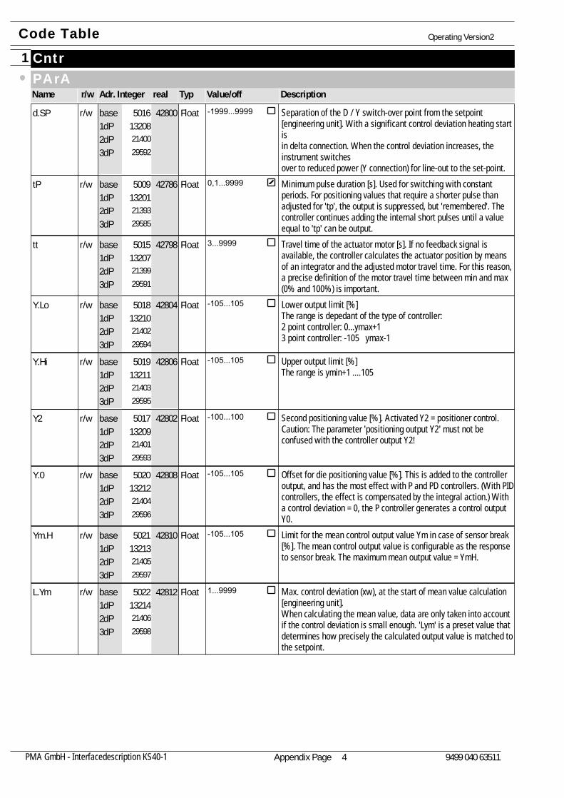
Separation of the D / Y switch-over point from the setpoint[engineering unit]. With a significant control deviation heating start isin delta connection. When the control deviation increases, theinstrument switchesover to reduced power (Y connection) for line-out to the set-point.
d.SP132082140029592
42800r/w Float -1999...99995016base1dP2dP3dP
Minimum pulse duration [s]. Used for switching with constantperiods. For positioning values that require a shorter pulse thanadjusted for 'tp', the output is suppressed, but 'remembered'. Thecontroller continues adding the internal short pulses until a valueequal to 'tp' can be output.
tP132012139329585
42786r/w Float 0,1...99995009base1dP2dP3dP
Travel time of the actuator motor [s]. If no feedback signal isavailable, the controller calculates the actuator position by meansof an integrator and the adjusted motor travel time. For this reason,a precise definition of the motor travel time between min and max(0% and 100%) is important.
tt132072139929591
42798r/w Float 3...99995015base1dP2dP3dP
Lower output limit [%]The range is depedant of the type of controller:2 point controller: 0...ymax+13 point controller: -105 ymax-1
Y.Lo132102140229594
42804r/w Float -105...1055018base1dP2dP3dP
Upper output limit [%]The range is ymin+1 ....105
Y.Hi132112140329595
42806r/w Float -105...1055019base1dP2dP3dP
Second positioning value [%]. Activated Y2 = positioner control.Caution: The parameter 'positioning output Y2' must not beconfused with the controller output Y2!
Y2132092140129593
42802r/w Float -100...1005017base1dP2dP3dP
Offset for die positioning value [%]. This is added to the controlleroutput, and has the most effect with P and PD controllers. (With PIDcontrollers, the effect is compensated by the integral action.) Witha control deviation = 0, the P controller generates a control outputY0.
Y.0132122140429596
42808r/w Float -105...1055020base1dP2dP3dP
Limit for the mean control output value Ym in case of sensor break[%]. The mean control output value is configurable as the responseto sensor break. The maximum mean output value = YmH.
Ym.H132132140529597
42810r/w Float -105...1055021base1dP2dP3dP
Max. control deviation (xw), at the start of mean value calculation[engineering unit].When calculating the mean value, data are only taken into accountif the control deviation is small enough. 'Lym' is a preset value thatdetermines how precisely the calculated output value is matched tothe setpoint.
L.Ym132142140629598
42812r/w Float 1...99995022base1dP2dP3dP
Code Table Operating Version2
Appendix Page 4PMA GmbH - Interfacedescription KS40-1 9499 040 63511
Cntr1SignalName Adr. Integer realr/w Typ Value/off Description
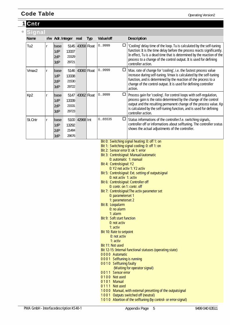
'Cooling' delay time of the loop. Tu is calculated by the self-tuningfunction: It is the time delay before the process reacts significantly.In effect, Tu is a dead time that is determined by the reaction of theprocess to a change of the control output. It is used for definingcontroller action.
Tu2133372152929721
43058r Float 0...99995145base1dP2dP3dP
Max. rate of change for 'cooling', i.e. the fastest process valueincrease during self-tuning. Vmax is calculated by the self-tuningfunction, and is determined by the reaction of the process to achange of the control output. It is used for defining controlleraction.
Vmax2133382153029722
43060r Float 0...99995146base1dP2dP3dP
Process gain for 'cooling'. For control loops with self-regulation,process gain is the ratio determined by the change of the controloutput and the resulting permanent change of the process value. Kpis calculated by the self-tuning function, and is used for definingcontroller action.
Kp2133392153129723
43062r Float 0...99995147base1dP2dP3dP
Status informations of the controller.f.e. switching signals,controller off or informations about selftuning. The controller sratusshows the actual adjustments of the controller.
Bit 0: Switching signal heating: 0: off 1: onBit 1: Switching signal cooling: 0: off 1: on Bit 2: Sensor error 0: ok 1: errorBit 3: Controlsignal: Manual/automatic 0: automatic 1: manualBit 4: Controlsignal: Y2 0: Y2 not activ 1: Y2 activBit 5: Controlsignal: Ext. setting of outputsignal 0: not activ 1: activBit 6: Controlsignal: Controller off 0: contr. on 1: contr. offBit 7: Controlsignal:The activ parameter set 0: parameterset 1 1: parameterset 2Bit 8: Loopalarm 0: no alarm 1: alarmBit 9: Soft start function 0: not activ 1: activBit 10: Rate to setpoint 0: not activ 1: activBit 11: Not usedBit 12-15: Internal functional statuses (operating state)0 0 0 0 Automatic0 0 0 1 Selftuning is running0 0 1 0 Selftuning faulty (Waiting for operator signal)0 0 1 1 Sensor error0 1 0 0 Not used0 1 0 1 Manual0 1 1 1 Not used1 0 0 0 Manual, with external presetting of the outputsignal1 0 0 1 Outputs switched off (neutral)1 0 1 0 Abortion of the selftuning (by control- or error-signal)
St.Cntr132922148429676
42968r Int 0...655355100base1dP2dP3dP
Code Table Operating Version2
Appendix Page 5PMA GmbH - Interfacedescription KS40-1 9499 040 63511
Cntr1SignalName Adr. Integer realr/w Typ Value/off Description
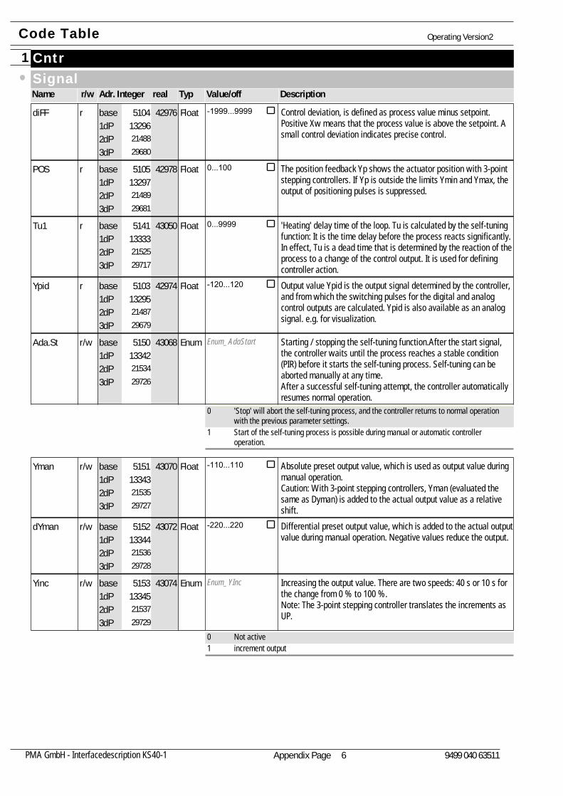
Control deviation, is defined as process value minus setpoint.Positive Xw means that the process value is above the setpoint. Asmall control deviation indicates precise control.
diFF132962148829680
42976r Float -1999...99995104base1dP2dP3dP
The position feedback Yp shows the actuator position with 3-pointstepping controllers. If Yp is outside the limits Ymin and Ymax, theoutput of positioning pulses is suppressed.
POS132972148929681
42978r Float 0...1005105base1dP2dP3dP
'Heating' delay time of the loop. Tu is calculated by the self-tuningfunction: It is the time delay before the process reacts significantly.In effect, Tu is a dead time that is determined by the reaction of theprocess to a change of the control output. It is used for definingcontroller action.
Tu1133332152529717
43050r Float 0...99995141base1dP2dP3dP
Output value Ypid is the output signal determined by the controller,and from which the switching pulses for the digital and analogcontrol outputs are calculated. Ypid is also available as an analogsignal. e.g. for visualization.
Ypid132952148729679
42974r Float -120...1205103base1dP2dP3dP
Enum_AdaStart Starting / stopping the self-tuning function.After the start signal,the controller waits until the process reaches a stable condition(PIR) before it starts the self-tuning process. Self-tuning can beaborted manually at any time.After a successful self-tuning attempt, the controller automaticallyresumes normal operation.
Ada.St133422153429726
43068r/w Enum5150base1dP2dP3dP
0 'Stop' will abort the self-tuning process, and the controller returns to normal operationwith the previous parameter settings.
1 Start of the self-tuning process is possible during manual or automatic controlleroperation.
Absolute preset output value, which is used as output value duringmanual operation.Caution: With 3-point stepping controllers, Yman (evaluated thesame as Dyman) is added to the actual output value as a relativeshift.
Yman133432153529727
43070r/w Float -110...1105151base1dP2dP3dP
Differential preset output value, which is added to the actual outputvalue during manual operation. Negative values reduce the output.
dYman133442153629728
43072r/w Float -220...2205152base1dP2dP3dP
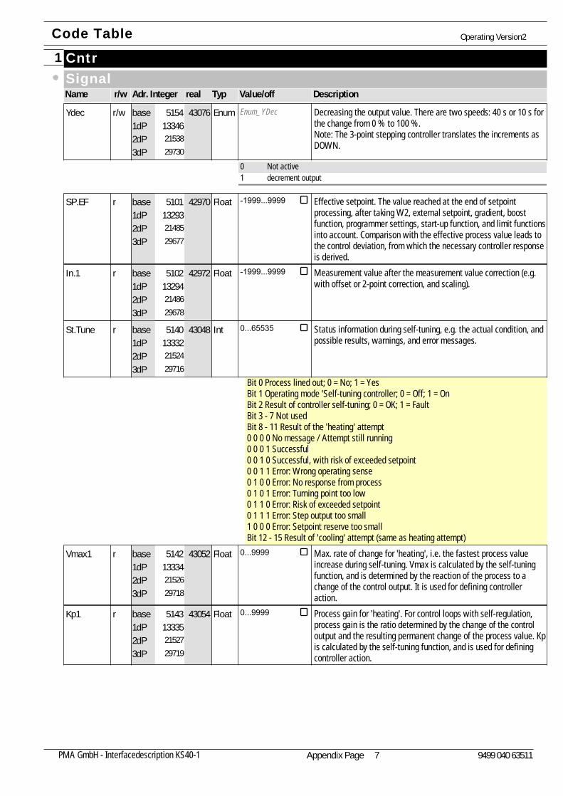
Enum_YInc Increasing the output value. There are two speeds: 40 s or 10 s forthe change from 0 % to 100 %.Note: The 3-point stepping controller translates the increments asUP.
Yinc133452153729729
43074r/w Enum5153base1dP2dP3dP
0 Not active1 increment output
Code Table Operating Version2
Appendix Page 6PMA GmbH - Interfacedescription KS40-1 9499 040 63511
Cntr1SignalName Adr. Integer realr/w Typ Value/off Description
Enum_YDec Decreasing the output value. There are two speeds: 40 s or 10 s forthe change from 0 % to 100 %.Note: The 3-point stepping controller translates the increments asDOWN.
Ydec133462153829730
43076r/w Enum5154base1dP2dP3dP
0 Not active1 decrement output
Effective setpoint. The value reached at the end of setpointprocessing, after taking W2, external setpoint, gradient, boostfunction, programmer settings, start-up function, and limit functionsinto account. Comparison with the effective process value leads tothe control deviation, from which the necessary controller responseis derived.
SP.EF132932148529677
42970r Float -1999...99995101base1dP2dP3dP
Measurement value after the measurement value correction (e.g.with offset or 2-point correction, and scaling).
In.1132942148629678
42972r Float -1999...99995102base1dP2dP3dP
Status information during self-tuning, e.g. the actual condition, andpossible results, warnings, and error messages.
Bit 0 Process lined out; 0 = No; 1 = YesBit 1 Operating mode 'Self-tuning controller; 0 = Off; 1 = OnBit 2 Result of controller self-tuning; 0 = OK; 1 = FaultBit 3 - 7 Not usedBit 8 - 11 Result of the 'heating' attempt0 0 0 0 No message / Attempt still running0 0 0 1 Successful0 0 1 0 Successful, with risk of exceeded setpoint0 0 1 1 Error: Wrong operating sense0 1 0 0 Error: No response from process0 1 0 1 Error: Turning point too low0 1 1 0 Error: Risk of exceeded setpoint0 1 1 1 Error: Step output too small1 0 0 0 Error: Setpoint reserve too smallBit 12 - 15 Result of 'cooling' attempt (same as heating attempt)
St.Tune133322152429716
43048r Int 0...655355140base1dP2dP3dP
Max. rate of change for 'heating', i.e. the fastest process valueincrease during self-tuning. Vmax is calculated by the self-tuningfunction, and is determined by the reaction of the process to achange of the control output. It is used for defining controlleraction.
Vmax1133342152629718
43052r Float 0...99995142base1dP2dP3dP
Process gain for 'heating'. For control loops with self-regulation,process gain is the ratio determined by the change of the controloutput and the resulting permanent change of the process value. Kpis calculated by the self-tuning function, and is used for definingcontroller action.
Kp1133352152729719
43054r Float 0...99995143base1dP2dP3dP
Code Table Operating Version2
Appendix Page 7PMA GmbH - Interfacedescription KS40-1 9499 040 63511
Cntr1SignalName Adr. Integer realr/w Typ Value/off Description
Code Table Operating Version2
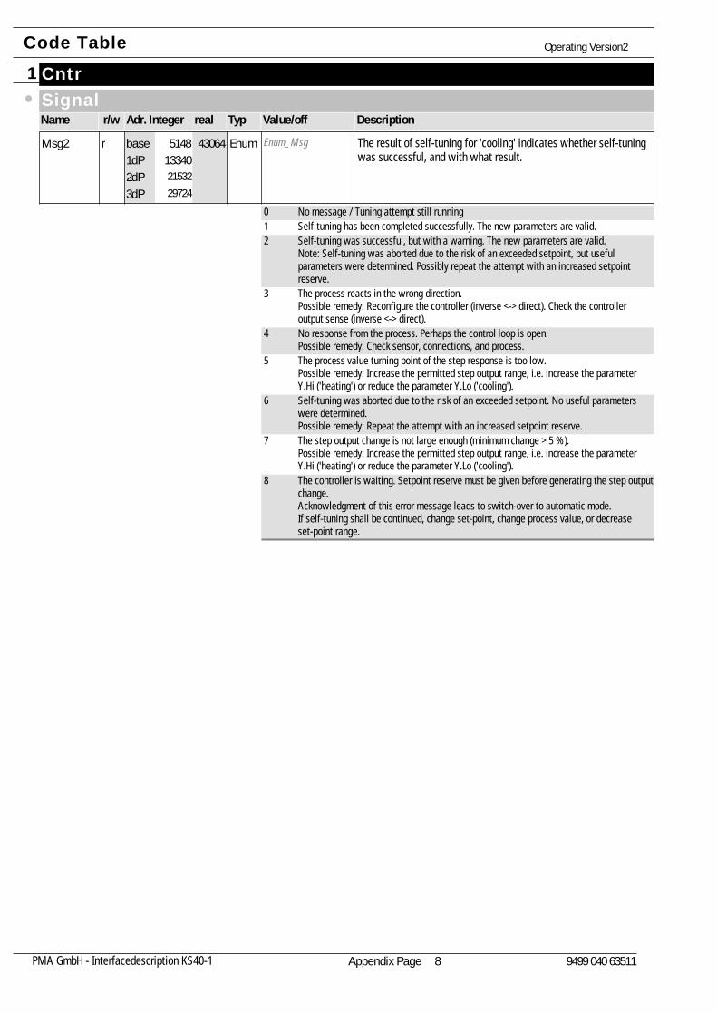
Enum_Msg The result of self-tuning for 'cooling' indicates whether self-tuningwas successful, and with what result.
Msg2133402153229724
43064r Enum5148base1dP2dP3dP
0 No message / Tuning attempt still running1 Self-tuning has been completed successfully. The new parameters are valid.2 Self-tuning was successful, but with a warning. The new parameters are valid.
Note: Self-tuning was aborted due to the risk of an exceeded setpoint, but usefulparameters were determined. Possibly repeat the attempt with an increased setpointreserve.
3 The process reacts in the wrong direction.Possible remedy: Reconfigure the controller (inverse <-> direct). Check the controlleroutput sense (inverse <-> direct).
4 No response from the process. Perhaps the control loop is open.Possible remedy: Check sensor, connections, and process.
5 The process value turning point of the step response is too low.Possible remedy: Increase the permitted step output range, i.e. increase the parameterY.Hi ('heating') or reduce the parameter Y.Lo ('cooling').
6 Self-tuning was aborted due to the risk of an exceeded setpoint. No useful parameterswere determined.Possible remedy: Repeat the attempt with an increased setpoint reserve.
7 The step output change is not large enough (minimum change > 5 %).Possible remedy: Increase the permitted step output range, i.e. increase the parameterY.Hi ('heating') or reduce the parameter Y.Lo ('cooling').
8 The controller is waiting. Setpoint reserve must be given before generating the step outputchange.Acknowledgment of this error message leads to switch-over to automatic mode. If self-tuning shall be continued, change set-point, change process value, or decreaseset-point range.
Appendix Page 8PMA GmbH - Interfacedescription KS40-1 9499 040 63511
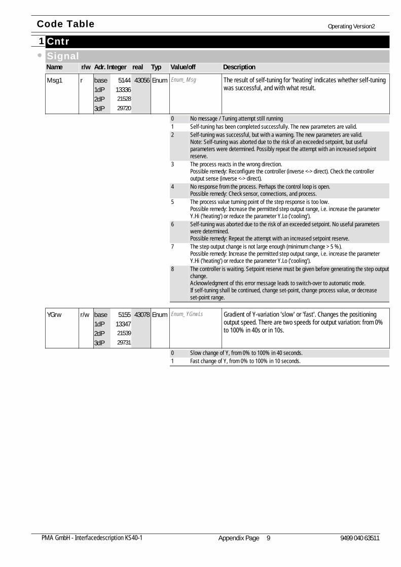
Cntr1SignalName Adr. Integer realr/w Typ Value/off Description
Enum_Msg The result of self-tuning for 'heating' indicates whether self-tuningwas successful, and with what result.
Msg1133362152829720
43056r Enum5144base1dP2dP3dP
0 No message / Tuning attempt still running1 Self-tuning has been completed successfully. The new parameters are valid.2 Self-tuning was successful, but with a warning. The new parameters are valid.
Note: Self-tuning was aborted due to the risk of an exceeded setpoint, but usefulparameters were determined. Possibly repeat the attempt with an increased setpointreserve.
3 The process reacts in the wrong direction.Possible remedy: Reconfigure the controller (inverse <-> direct). Check the controlleroutput sense (inverse <-> direct).
4 No response from the process. Perhaps the control loop is open.Possible remedy: Check sensor, connections, and process.
5 The process value turning point of the step response is too low.Possible remedy: Increase the permitted step output range, i.e. increase the parameterY.Hi ('heating') or reduce the parameter Y.Lo ('cooling').
6 Self-tuning was aborted due to the risk of an exceeded setpoint. No useful parameterswere determined.Possible remedy: Repeat the attempt with an increased setpoint reserve.
7 The step output change is not large enough (minimum change > 5 %).Possible remedy: Increase the permitted step output range, i.e. increase the parameterY.Hi ('heating') or reduce the parameter Y.Lo ('cooling').
8 The controller is waiting. Setpoint reserve must be given before generating the step outputchange.Acknowledgment of this error message leads to switch-over to automatic mode. If self-tuning shall be continued, change set-point, change process value, or decreaseset-point range.
Enum_YGrwLs Gradient of Y-variation 'slow' or 'fast'. Changes the positioningoutput speed. There are two speeds for output variation: from 0%to 100% in 40s or in 10s.
YGrw133472153929731
43078r/w Enum5155base1dP2dP3dP
0 Slow change of Y, from 0% to 100% in 40 seconds.1 Fast change of Y, from 0% to 100% in 10 seconds.
Code Table Operating Version2
Appendix Page 9PMA GmbH - Interfacedescription KS40-1 9499 040 63511
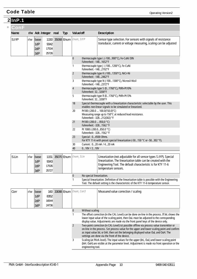
InP.12ConFName Adr. Integer realr/w Typ Value/off Description
Enum_StYP Sensor type selection. For sensors with signals of resistancetransducer, current or voltage measuring, scaling can be adjusted
S.tYP9342
1753425726
35068r/w Enum1150base1dP2dP3dP
0 thermocouple type L (-100...900°C), Fe-CuNi DINFahrenheit: -148...1652°F
1 thermocouple type J (-100...1200°C), Fe-CuNiFahrenheit: -148...2192°F
2 thermocouple type K (-100...1350°C), NiCr-NiFahrenheit: -148...2462°F
3 thermocouple type N (-100...1300°C), Nicrosil-NisilFahrenheit: -148...2372°F
4 thermocouple type S (0...1760°C), PtRh-Pt10%Fahrenheit: 32...3200°F
5 thermocouple type R (0...1760°C), PtRh-Pt13%Fahrenheit: 32...3200°F
18 Special thermocouple with a linearization characteristic selectable by the user. Thisenables non-linear signals to be simulated or linearized.
20 Pt100 (-200.0 ... 100.0(150.0)°C)Measuring range up to 150°C at reduced lead resistance.Fahrenheit: -328...212(302) °F
21 Pt100 (-200.0 ... 850,0 °C)Fahrenheit: -328...1562 °F
22 Pt 1000 (-200.0...850.0 °C)Fahrenheit: -328...1562 °F
23 Special : 0...4500 Ohms.For KTY 11-6 with preset special linearization (-50...150 °C or -58...302 °F).
30 Current : 0...20 mA / 4...20 mA40 0...10V / 2...10V
Enum_SLin Linearization (not adjustable for all sensor types S.tYP). Speciallinearization. The linearization table can be created with the Engineering Tool. The default characteristic is for KTY 11-6temperature sensors.
S.Lin9343
1753525727
35070r/w Enum1151base1dP2dP3dP
0 No special linearization.1 Special linearization. Definition of the linearization table is possible with the Engineering
Tool. The default setting is the characteristic of the KTY 11-6 temperature sensor.
Enum_Corr3 Measured value correction / scalingCorr8352
1654424736
33088r/w Enum160base1dP2dP3dP
0 Without scaling1 The offset correction (in the CAL Level) can be done on-line in the process. If InL shows the
lower input value of the scaling point, then OuL must be adjusted to the correspondingdisplay value. Adjustments are made via the front panel keys of the device only.
2 Two-point correction (in CAL-Level) ist possible offline via process value transmitter oron-line in the process. Set process value for the upper and lower scaling point and confirmas input value InL or InH, then set the belonging displayed value OuL and OuH. Thesettings are done via the front of the device.
3 Scaling (at PArA-level). The input values for the upper (InL, OuL) and lower scaling point(InH. OuH) are visible at the parameter level. Adjustment is made via front operation or theengineering tool.
Code Table Operating Version2
Appendix Page 10PMA GmbH - Interfacedescription KS40-1 9499 040 63511
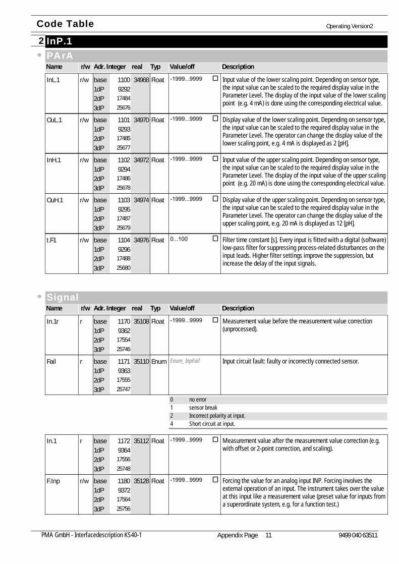
InP.12PArAName Adr. Integer realr/w Typ Value/off Description
Input value of the lower scaling point. Depending on sensor type,the input value can be scaled to the required display value in theParameter Level. The display of the input value of the lower scalingpoint (e.g. 4 mA) is done using the corresponding electrical value.
InL.19292
1748425676
34968r/w Float -1999...99991100base1dP2dP3dP
Display value of the lower scaling point. Depending on sensor type,the input value can be scaled to the required display value in theParameter Level. The operator can change the display value of thelower scaling point, e.g. 4 mA is displayed as 2 [pH].
OuL.19293
1748525677
34970r/w Float -1999...99991101base1dP2dP3dP
Input value of the upper scaling point. Depending on sensor type,the input value can be scaled to the required display value in theParameter Level. The display of the input value of the upper scalingpoint (e.g. 20 mA) is done using the corresponding electrical value.
InH.19294
1748625678
34972r/w Float -1999...99991102base1dP2dP3dP
Display value of the upper scaling point. Depending on sensor type,the input value can be scaled to the required display value in theParameter Level. The operator can change the display value of theupper scaling point, e.g. 20 mA is displayed as 12 [pH].
OuH.19295
1748725679
34974r/w Float -1999...99991103base1dP2dP3dP
Filter time constant [s]. Every input is fitted with a digital (software)low-pass filter for suppressing process-related disturbances on theinput leads. Higher filter settings improve the suppression, but increase the delay of the input signals.
t.F19296
1748825680
34976r/w Float 0...1001104base1dP2dP3dP
SignalName Adr. Integer realr/w Typ Value/off Description
Measurement value before the measurement value correction(unprocessed).
In.1r9362
1755425746
35108r Float -1999...99991170base1dP2dP3dP
Enum_InpFail Input circuit fault: faulty or incorrectly connected sensor.Fail9363
1755525747
35110r Enum1171base1dP2dP3dP
0 no error1 sensor break2 Incorrect polarity at input.4 Short circuit at input.
Measurement value after the measurement value correction (e.g.with offset or 2-point correction, and scaling).
In.19364
1755625748
35112r Float -1999...99991172base1dP2dP3dP
Forcing the value for an analog input INP. Forcing involves theexternal operation of an input. The instrument takes over the valueat this input like a measurement value (preset value for inputs froma superordinate system, e.g. for a function test.)
F.Inp9372
1756425756
35128r/w Float -1999...99991180base1dP2dP3dP
Code Table Operating Version2
Appendix Page 11PMA GmbH - Interfacedescription KS40-1 9499 040 63511
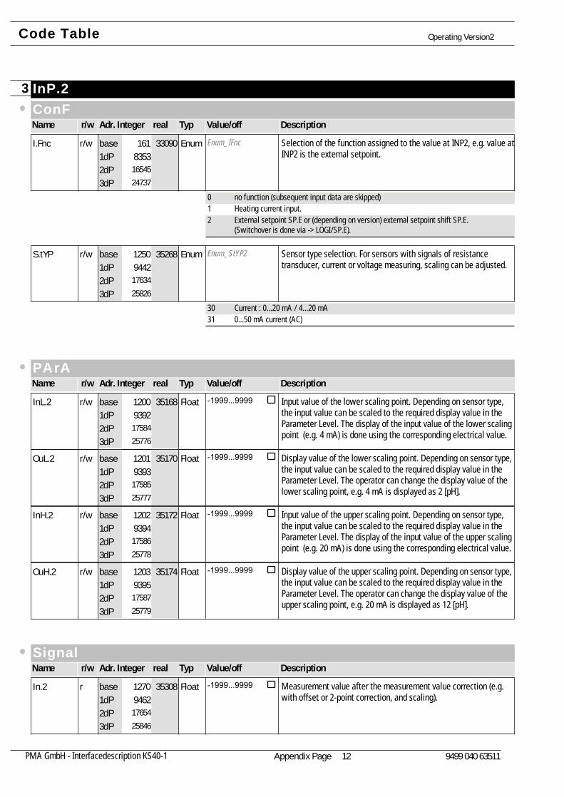
InP.23ConFName Adr. Integer realr/w Typ Value/off Description
Enum_IFnc Selection of the function assigned to the value at INP2, e.g. value atINP2 is the external setpoint.
I.Fnc8353
1654524737
33090r/w Enum161base1dP2dP3dP
0 no function (subsequent input data are skipped)1 Heating current input.2 External setpoint SP.E or (depending on version) external setpoint shift SP.E.
(Switchover is done via -> LOGI/SP.E).
Enum_StYP2 Sensor type selection. For sensors with signals of resistancetransducer, current or voltage measuring, scaling can be adjusted.
S.tYP9442
1763425826
35268r/w Enum1250base1dP2dP3dP
30 Current : 0...20 mA / 4...20 mA31 0...50 mA current (AC)
PArAName Adr. Integer realr/w Typ Value/off Description
Input value of the lower scaling point. Depending on sensor type,the input value can be scaled to the required display value in theParameter Level. The display of the input value of the lower scalingpoint (e.g. 4 mA) is done using the corresponding electrical value.
InL.29392
1758425776
35168r/w Float -1999...99991200base1dP2dP3dP
Display value of the lower scaling point. Depending on sensor type,the input value can be scaled to the required display value in theParameter Level. The operator can change the display value of thelower scaling point, e.g. 4 mA is displayed as 2 [pH].
OuL.29393
1758525777
35170r/w Float -1999...99991201base1dP2dP3dP
Input value of the upper scaling point. Depending on sensor type,the input value can be scaled to the required display value in theParameter Level. The display of the input value of the upper scalingpoint (e.g. 20 mA) is done using the corresponding electrical value.
InH.29394
1758625778
35172r/w Float -1999...99991202base1dP2dP3dP
Display value of the upper scaling point. Depending on sensor type,the input value can be scaled to the required display value in theParameter Level. The operator can change the display value of theupper scaling point, e.g. 20 mA is displayed as 12 [pH].
OuH.29395
1758725779
35174r/w Float -1999...99991203base1dP2dP3dP
SignalName Adr. Integer realr/w Typ Value/off Description
Measurement value after the measurement value correction (e.g.with offset or 2-point correction, and scaling).
In.29462
1765425846
35308r Float -1999...99991270base1dP2dP3dP
Code Table Operating Version2
Appendix Page 12PMA GmbH - Interfacedescription KS40-1 9499 040 63511
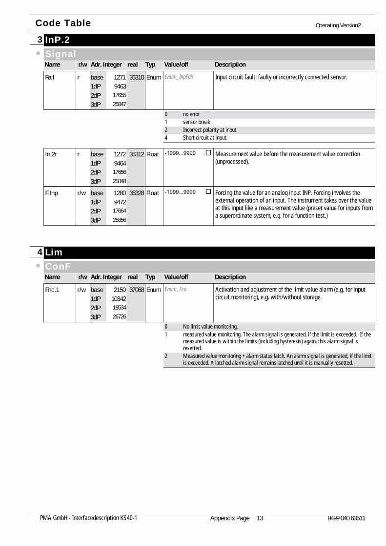
InP.23SignalName Adr. Integer realr/w Typ Value/off Description
Enum_InpFail Input circuit fault: faulty or incorrectly connected sensor.Fail9463
1765525847
35310r Enum1271base1dP2dP3dP
0 no error1 sensor break2 Incorrect polarity at input.4 Short circuit at input.
Measurement value before the measurement value correction(unprocessed).
In.2r9464
1765625848
35312r Float -1999...99991272base1dP2dP3dP
Forcing the value for an analog input INP. Forcing involves theexternal operation of an input. The instrument takes over the valueat this input like a measurement value (preset value for inputs froma superordinate system, e.g. for a function test.)
F.Inp9472
1766425856
35328r/w Float -1999...99991280base1dP2dP3dP
Lim4ConFName Adr. Integer realr/w Typ Value/off Description
Enum_Fcn Activation and adjustment of the limit value alarm (e.g. for inputcircuit monitoring), e.g. with/without storage.
Fnc.1103421853426726
37068r/w Enum2150base1dP2dP3dP
0 No limit value monitoring.1 measured value monitoring. The alarm signal is generated, if the limit is exceeded. If the
measured value is within the limits (including hysteresis) again, this alarm signal isresetted.
2 Measured value monitoring + alarm status latch. An alarm signal is generated, if the limitis exceeded. A latched alarm signal remains latched until it is manually resetted.
Code Table Operating Version2
Appendix Page 13PMA GmbH - Interfacedescription KS40-1 9499 040 63511

Lim4ConFName Adr. Integer realr/w Typ Value/off Description
Enum_Src Source for limit value. Selection of which value is to be monitored.Src.1103431853526727
37070r/w Enum2151base1dP2dP3dP
0 Process value = absolute alarm1 control deviation xw (process value - set-point) = relative alarm
Note: Monitoring with the effective set-point Weff. For example using a ramp it is thechanging set-point, not the target set-point of the ramp.
2 Control deviation Xw (= relative alarm) with suppression during start-up and setpointchanges. Limit value monitoring is continued as soon as the control deviation comeswithin the alarm limits again, at the latest after 10 * Tn.
6 effective set-point Weff. For example the ramp-function changes the effective set-point untill it matches theinternal (target) set-point.
7 correcting variable y (controller output)11 Control deviation Xw (= relative alarm) with suppression during start-up and setpoint
change. Limit value monitoring is continued as soon as the control deviation comes withinthe alarm limits again.
Enum_HCAL Activation of alarm heat current function. Either overload or breakcan be monitored, overload = current I > heat current limit, or break= current I < heat current limit. Short circuit is monitored in bothcases.
HC.AL102421843426626
36868r/w Enum2050base1dP2dP3dP
0 No heating current alarm.1 Overload and short circuit monitoring. Overload = current I > heat current limit.2 Break and short circuit monitoring. Break = current I < heat current limit.
Enum_LPAL Monitoring of control loop interruption (not possible with 3-pointstepping controller, not possible with signaller)
LP.AL132502144229634
42884r/w Enum5058base1dP2dP3dP
0 switched off / inactive1 LOOP alarm is generated, if with Y=100% there is no corresponding reaction of the
process variable within the time of 2 x ti.Possible remedial action: Check heating or cooling circuit, check sensor and replace it, ifnecessary, check controller and switchingdevice.
PArAName Adr. Integer realr/w Typ Value/off Description
Lower limit value. The alarm is triggered if the value falls below thelimit, and is reset with lower limit value plus hysteresis.
L.1102921848426676
36968r/w Float -1999...99992100base1dP2dP3dP
Upper limit value. The alarm is triggered if the value rises above thelimit, and is reset with upper lower limit value plus hysteresis.
H.1102931848526677
36970r/w Float -1999...99992101base1dP2dP3dP
Code Table Operating Version2
Appendix Page 14PMA GmbH - Interfacedescription KS40-1 9499 040 63511
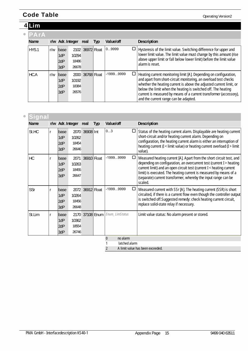
Lim4PArAName Adr. Integer realr/w Typ Value/off Description
Hysteresis of the limit value. Switching difference for upper andlower limit value. The limit value must change by this amount (riseabove upper limit or fall below lower limit) before the limit valuealarm is reset.
HYS.1102941848626678
36972r/w Float 0...99992102base1dP2dP3dP
Heating current monitoring limit [A]. Depending on configuration,and apart from short-circuit monitoring, an overload test checkswhether the heating current is above the adjusted current limit, orbelow the limit when the heating is switched off. The heatingcurrent is measured by means of a current transformer (accessory),and the current range can be adapted.
HC.A101921838426576
36768r/w Float -1999...99992000base1dP2dP3dP
SignalName Adr. Integer realr/w Typ Value/off Description
Status of the heating current alarm. Displayable are heating currentshort-circuit and/or heating current alarm. Depending onconfiguration, the heating current alarm is either an interruption ofheating current (I < limit value) or heating current overload (I > limitvalue).
St.HC102621845426646
36908r Int 0...32070base1dP2dP3dP
Measured heating current [A]. Apart from the short circuit test, anddepending on configuration, an overcurrent test (current I > heatingcurrent limit) and an open circuit test (current I < heating currentlimit) is executed. The heating current is measured by means of a(separate) current transformer, whereby the input range can bescaled.
HC102631845526647
36910r Float -1999...99992071base1dP2dP3dP
Measured current with SSr [A]. The heating current (SSR) is shortcircuited, if there is a current flow even though the controller outputis switched off.Suggested remedy: check heating current circuit,replace solid-state relay if necessary.
SSr102641845626648
36912r Float -1999...99992072base1dP2dP3dP
Enum_LimStatus Limit value status: No alarm present or stored.St.Lim103621855426746
37108r Enum2170base1dP2dP3dP
0 no alarm1 latched alarm2 A limit value has been exceeded.
Code Table Operating Version2
Appendix Page 15PMA GmbH - Interfacedescription KS40-1 9499 040 63511
Lim25ConFName Adr. Integer realr/w Typ Value/off Description
Enum_Fcn Activation and adjustment of the limit value alarm (e.g. for inputcircuit monitoring), e.g. with/without storage.
Fnc.2104421863426826
37268r/w Enum2250base1dP2dP3dP
0 No limit value monitoring.1 measured value monitoring. The alarm signal is generated, if the limit is exceeded. If the
measured value is within the limits (including hysteresis) again, this alarm signal isresetted.
2 Measured value monitoring + alarm status latch. An alarm signal is generated, if the limitis exceeded. A latched alarm signal remains latched until it is manually resetted.
Enum_Src Source for limit value. Selection of which value is to be monitored.Src.2104431863526827
37270r/w Enum2251base1dP2dP3dP
0 Process value = absolute alarm1 control deviation xw (process value - set-point) = relative alarm
Note: Monitoring with the effective set-point Weff. For example using a ramp it is thechanging set-point, not the target set-point of the ramp.
2 Control deviation Xw (= relative alarm) with suppression during start-up and setpointchanges. Limit value monitoring is continued as soon as the control deviation comeswithin the alarm limits again, at the latest after 10 * Tn.
6 effective set-point Weff. For example the ramp-function changes the effective set-point untill it matches theinternal (target) set-point.
7 correcting variable y (controller output)11 Control deviation Xw (= relative alarm) with suppression during start-up and setpoint
change. Limit value monitoring is continued as soon as the control deviation comes withinthe alarm limits again.
PArAName Adr. Integer realr/w Typ Value/off Description
Lower limit value. The alarm is triggered if the value falls below thelimit, and is reset with lower limit value plus hysteresis.
L.2103921858426776
37168r/w Float -1999...99992200base1dP2dP3dP
Upper limit value. The alarm is triggered if the value rises above thelimit, and is reset with upper lower limit value plus hysteresis.
H.2103931858526777
37170r/w Float -1999...99992201base1dP2dP3dP
Hysteresis of the limit value. Switching difference for upper andlower limit value. The limit value must change by this amount (riseabove upper limit or fall below lower limit) before the limit valuealarm is reset.
HYS.2103941858626778
37172r/w Float 0...99992202base1dP2dP3dP
Code Table Operating Version2
Appendix Page 16PMA GmbH - Interfacedescription KS40-1 9499 040 63511
Lim25SignalName Adr. Integer realr/w Typ Value/off Description
Enum_LimStatus Limit value status: No alarm present or stored.St.Lim104621865426846
37308r Enum2270base1dP2dP3dP
0 no alarm1 latched alarm2 A limit value has been exceeded.
Lim36ConFName Adr. Integer realr/w Typ Value/off Description
Enum_Fcn Activation and adjustment of the limit value alarm (e.g. for inputcircuit monitoring), e.g. with/without storage.
Fnc.3105421873426926
37468r/w Enum2350base1dP2dP3dP
0 No limit value monitoring.1 measured value monitoring. The alarm signal is generated, if the limit is exceeded. If the
measured value is within the limits (including hysteresis) again, this alarm signal isresetted.
2 Measured value monitoring + alarm status latch. An alarm signal is generated, if the limitis exceeded. A latched alarm signal remains latched until it is manually resetted.
Enum_Src Source for limit value. Selection of which value is to be monitored.Src.3105431873526927
37470r/w Enum2351base1dP2dP3dP
0 Process value = absolute alarm1 control deviation xw (process value - set-point) = relative alarm
Note: Monitoring with the effective set-point Weff. For example using a ramp it is thechanging set-point, not the target set-point of the ramp.
2 Control deviation Xw (= relative alarm) with suppression during start-up and setpointchanges. Limit value monitoring is continued as soon as the control deviation comeswithin the alarm limits again, at the latest after 10 * Tn.
6 effective set-point Weff. For example the ramp-function changes the effective set-point untill it matches theinternal (target) set-point.
7 correcting variable y (controller output)11 Control deviation Xw (= relative alarm) with suppression during start-up and setpoint
change. Limit value monitoring is continued as soon as the control deviation comes withinthe alarm limits again.
PArAName Adr. Integer realr/w Typ Value/off Description
Lower limit value. The alarm is triggered if the value falls below thelimit, and is reset with lower limit value plus hysteresis.
L.3104921868426876
37368r/w Float -1999...99992300base1dP2dP3dP
Code Table Operating Version2
Appendix Page 17PMA GmbH - Interfacedescription KS40-1 9499 040 63511
Lim36PArAName Adr. Integer realr/w Typ Value/off Description
Upper limit value. The alarm is triggered if the value rises above thelimit, and is reset with upper lower limit value plus hysteresis.
H.3104931868526877
37370r/w Float -1999...99992301base1dP2dP3dP
Hysteresis of the limit value. Switching difference for upper andlower limit value. The limit value must change by this amount (riseabove upper limit or fall below lower limit) before the limit valuealarm is reset.
HYS.3104941868626878
37372r/w Float 0...99992302base1dP2dP3dP
SignalName Adr. Integer realr/w Typ Value/off Description
Enum_LimStatus Limit value status: No alarm present or stored.St.Lim105621875426946
37508r Enum2370base1dP2dP3dP
0 no alarm1 latched alarm2 A limit value has been exceeded.
LOGI7ConFName Adr. Integer realr/w Typ Value/off Description
Enum_dInP1 Local / remote switchover (Remote: Adjustment of all values via thefront panel is blocked).
L_r9243
1743525627
34870r/w Enum1051base1dP2dP3dP
0 no function (switch-over via interface is possible)1 always active2 Digital Input DI1 switches3 DI2 switches (only visible with OPTION)4 DI3 switches (only visible with OPTION)
Enum_dInP4 Source of the control signal for activating the second (safety)setpoint (SP.2=) W2.Note: W2 is not restricted by the setpoint limits.
SP.29244
1743625628
34872r/w Enum1052base1dP2dP3dP
0 no function (switch-over via interface is possible)2 Digital Input DI1 switches3 DI2 switches (only visible with OPTION)4 DI3 switches (only visible with OPTION)
Code Table Operating Version2
Appendix Page 18PMA GmbH - Interfacedescription KS40-1 9499 040 63511
LOGI7ConFName Adr. Integer realr/w Typ Value/off Description
Enum_dInP1 Switching between internal set-point an external setpoint SP.E. Theexternal SP.E is either the absolute set-point Wext or the offset tothe set-point (dependent on instrument and configuration).
SP.E9245
1743725629
34874r/w Enum1053base1dP2dP3dP
0 no function (switch-over via interface is possible)1 always active2 Digital Input DI1 switches3 DI2 switches (only visible with OPTION)4 DI3 switches (only visible with OPTION)
Enum_dInP3 Source of the control signal for activating the second positioningoutput Y2. Activated Y2 = positioner control.Caution: The parameter 'positioning output Y2' must not beconfused with the controller output Y2!
Y29246
1743825630
34876r/w Enum1054base1dP2dP3dP
0 no function (switch-over via interface is possible)2 Digital Input DI1 switches3 DI2 switches (only visible with OPTION)4 DI3 switches (only visible with OPTION)6 Auto/manual key switches (A/M key)
Enum_dInp2 Source of the control signal for auto/manual switchover. In theautomatic mode, the controller is in charge. In the manual mode,the outputs can be varied independently of the process.
mAn9248
1744025632
34880r/w Enum1056base1dP2dP3dP
0 no function (switch-over via interface is possible)1 always activated (manual station)2 Digital Input DI1 switches3 DI2 switches (only visible with OPTION)4 DI3 switches (only visible with OPTION)6 Auto/manual key switches (A/M key)
Enum_dInP3 Source of the control signal for disabling all the controlleroutputs.Note: Forcing has priority, and remains active; alarmprocessing also remains active.
C.oFF9249
1744125633
34882r/w Enum1057base1dP2dP3dP
0 no function (switch-over via interface is possible)2 Digital Input DI1 switches3 DI2 switches (only visible with OPTION)4 DI3 switches (only visible with OPTION)6 Auto/manual key switches (A/M key)
Enum_dInp4 Source of the control signal to disable the auto/manual key. If theA/M key is disabled, switchover to manual operation is notpossible.
m.Loc9250
1744225634
34884r/w Enum1058base1dP2dP3dP
0 no function (switch-over via interface is possible)2 Digital Input DI1 switches3 DI2 switches (only visible with OPTION)4 DI3 switches (only visible with OPTION)
Code Table Operating Version2
Appendix Page 19PMA GmbH - Interfacedescription KS40-1 9499 040 63511
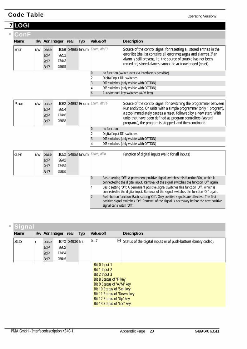
LOGI7ConFName Adr. Integer realr/w Typ Value/off Description
Enum_dInP3 Source of the control signal for resetting all stored entries in theerror list (the list contains all error messages and alarms). If analarm is still present, i.e. the source of trouble has not beenremedied, stored alarms cannot be acknowledged (reset).
Err.r9251
1744325635
34886r/w Enum1059base1dP2dP3dP
0 no function (switch-over via interface is possible)2 Digital Input DI1 switches3 DI2 switches (only visible with OPTION)4 DI3 switches (only visible with OPTION)6 Auto/manual key switches (A/M key)
Enum_dInP6 Source of the control signal for switching the programmer betweenRun and Stop. On units with a simple programmer (only 1 program),a stop immediately causes a reset, followed by a new start. Withunits that have been defined as program controllers (severalprograms), the program is stopped, and then continued.
P.run9254
1744625638
34892r/w Enum1062base1dP2dP3dP
0 no function2 Digital Input DI1 switches3 DI2 switches (only visible with OPTION)4 DI3 switches (only visible with OPTION)
Enum_diFn Function of digital inputs (valid for all inputs)di.Fn9242
1743425626
34868r/w Enum1050base1dP2dP3dP
0 Basic setting 'Off': A permanent positive signal switches this function 'On', which isconnected to the digital input. Removal of the signal switches the function 'Off' again.
1 Basic setting 'On': A permanent positive signal switches this function 'Off', which isconnected to the digital input. Removal of the signal switches the function 'On' again.
2 Push-button function. Basic setting 'Off'. Only positive signals are effective. The firstpositive signal switches 'On'. Removal of the signal is necessary before the next positivesignal can switch 'Off'.
SignalName Adr. Integer realr/w Typ Value/off Description
Status of the digital inputs or of push-buttons (binary coded).
Bit 0 Input 1Bit 1 Input 2Bit 2 Input 3Bit 8 Status of 'F' keyBit 9 Status of 'A/M' keyBit 10 Status of 'Sel' keyBit 11 Status of 'Down' keyBit 12 Status of 'Up' keyBit 13 Status of 'Loc' key
St.Di9262
1745425646
34908r Int 0...71070base1dP2dP3dP
Code Table Operating Version2
Appendix Page 20PMA GmbH - Interfacedescription KS40-1 9499 040 63511

LOGI7SignalName Adr. Integer realr/w Typ Value/off Description
Remote operation. Remote means that all values can only beadjusted via the interface. Adjustments via the front panel areblocked.
L-R9272
1746425656
34928r/w Int 0...11080base1dP2dP3dP
Signal for activating the second (safety) setpoint (SP.2=) W2.Note: Setpoint W2 is not restricted by the setpoint limits!
W_W29273
1746525657
34930r/w Int 0...11081base1dP2dP3dP
Signal for activating the external setpoint value. SP.E is the externalsetpoint, or dependent on the device and configuration of thesetpoint shift.
Wi_We9274
1746625658
34932r/w Int 0...11082base1dP2dP3dP
Signal for activating the 2nd output value Y2. With selected Y2, theoutput is operated as a positioner.Caution: Do not confuse theparameter 'fixed output Y2' with the controller output Y2!
Y_Y29275
1746725659
34934r/w Int 0...11083base1dP2dP3dP
Signal for activating manual operation. In the manual mode, thecontroller provides output signals independent of the process.
A-M9277
1746925661
34938r/w Int 0...11085base1dP2dP3dP
Signal for disabling all the controller outputs.Note: Forcing has priority; alarm processing remains active.
C.Off9278
1747025662
34940r/w Int 0...11086base1dP2dP3dP
Signal for disabling manual operation. Triggers a forced switchoverto automatic mode, and disables the front panel A/M key (also ifother functions have been assigned to the key).
L.AM9279
1747125663
34942r/w Int 0...11087base1dP2dP3dP
Signal for resetting the entire error list. The error list contains allerrors that are reported, e.g. device faults and limit values. It alsocontains queued as well as stored errors after their correction. Thereset acknowledges all errors, whereby queued errors will reappearafter the next error detection (measurement).
Err.r9280
1747225664
34944r/w Int 0...11088base1dP2dP3dP
Reset of the alarm triggered by a solid-state relay (SSR).SSRs are mostly used for frequent switching of heating elements,because they have no mechanical contacts that can wear out.However, an unnoticed short circuit could lead to overheating of themachine.
SSR.Res9281
1747325665
34946r/w Int 0...11089base1dP2dP3dP
Signal for starting the programmer. On units with a simpleprogrammer (only 1 program), a stop immediately causes a reset,followed by a new start. With units that have been defined asprogram controllers (several programs), the program is stopped, andthen continued.
Prg.R.S9284
1747625668
34952r/w Int 0...11092base1dP2dP3dP
Code Table Operating Version2
Appendix Page 21PMA GmbH - Interfacedescription KS40-1 9499 040 63511
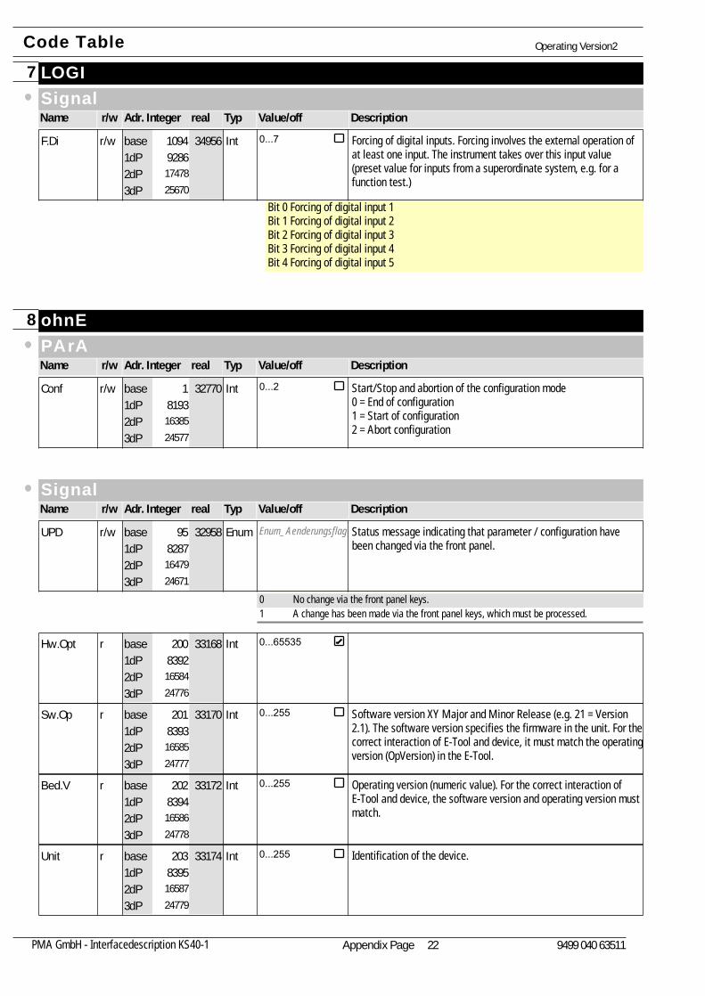
LOGI7SignalName Adr. Integer realr/w Typ Value/off Description
Forcing of digital inputs. Forcing involves the external operation ofat least one input. The instrument takes over this input value(preset value for inputs from a superordinate system, e.g. for afunction test.)
Bit 0 Forcing of digital input 1Bit 1 Forcing of digital input 2Bit 2 Forcing of digital input 3Bit 3 Forcing of digital input 4Bit 4 Forcing of digital input 5
F.Di9286
1747825670
34956r/w Int 0...71094base1dP2dP3dP
ohnE8PArAName Adr. Integer realr/w Typ Value/off Description
Start/Stop and abortion of the configuration mode0 = End of configuration1 = Start of configuration2 = Abort configuration
Conf8193
1638524577
32770r/w Int 0...21base1dP2dP3dP
SignalName Adr. Integer realr/w Typ Value/off Description
Enum_Aenderungsflag Status message indicating that parameter / configuration havebeen changed via the front panel.
UPD8287
1647924671
32958r/w Enum95base1dP2dP3dP
0 No change via the front panel keys.1 A change has been made via the front panel keys, which must be processed.
Hw.Opt8392
1658424776
33168r Int 0...65535200base1dP2dP3dP
Software version XY Major and Minor Release (e.g. 21 = Version2.1). The software version specifies the firmware in the unit. For thecorrect interaction of E-Tool and device, it must match the operatingversion (OpVersion) in the E-Tool.
Sw.Op8393
1658524777
33170r Int 0...255201base1dP2dP3dP
Operating version (numeric value). For the correct interaction ofE-Tool and device, the software version and operating version mustmatch.
Bed.V8394
1658624778
33172r Int 0...255202base1dP2dP3dP
Identification of the device.Unit8395
1658724779
33174r Int 0...255203base1dP2dP3dP
Code Table Operating Version2
Appendix Page 22PMA GmbH - Interfacedescription KS40-1 9499 040 63511
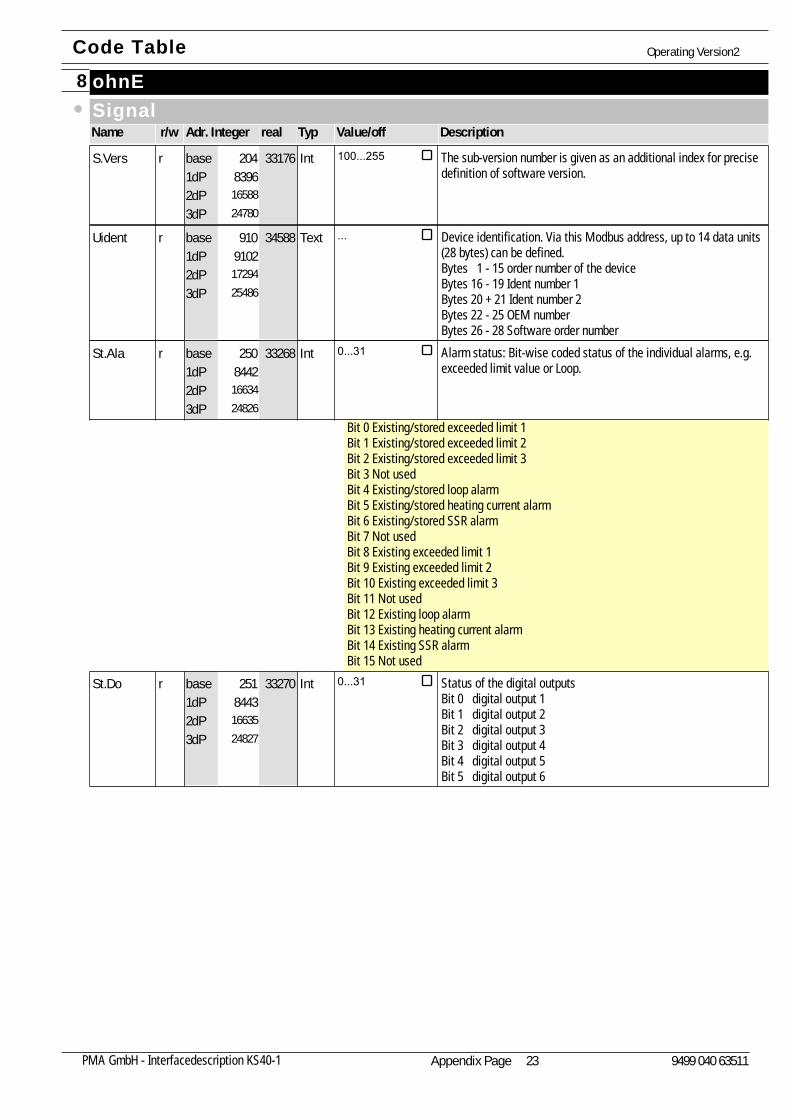
ohnE8SignalName Adr. Integer realr/w Typ Value/off Description
The sub-version number is given as an additional index for precisedefinition of software version.
S.Vers8396
1658824780
33176r Int 100...255204base1dP2dP3dP
Device identification. Via this Modbus address, up to 14 data units(28 bytes) can be defined.Bytes 1 - 15 order number of the deviceBytes 16 - 19 Ident number 1Bytes 20 + 21 Ident number 2Bytes 22 - 25 OEM numberBytes 26 - 28 Software order number
Uident9102
1729425486
34588r Text ...910base1dP2dP3dP
Alarm status: Bit-wise coded status of the individual alarms, e.g.exceeded limit value or Loop.
Bit 0 Existing/stored exceeded limit 1Bit 1 Existing/stored exceeded limit 2Bit 2 Existing/stored exceeded limit 3Bit 3 Not usedBit 4 Existing/stored loop alarmBit 5 Existing/stored heating current alarmBit 6 Existing/stored SSR alarmBit 7 Not usedBit 8 Existing exceeded limit 1Bit 9 Existing exceeded limit 2Bit 10 Existing exceeded limit 3Bit 11 Not usedBit 12 Existing loop alarmBit 13 Existing heating current alarmBit 14 Existing SSR alarmBit 15 Not used
St.Ala8442
1663424826
33268r Int 0...31250base1dP2dP3dP
Status of the digital outputsBit 0 digital output 1Bit 1 digital output 2Bit 2 digital output 3Bit 3 digital output 4Bit 4 digital output 5 Bit 5 digital output 6
St.Do8443
1663524827
33270r Int 0...31251base1dP2dP3dP
Code Table Operating Version2
Appendix Page 23PMA GmbH - Interfacedescription KS40-1 9499 040 63511
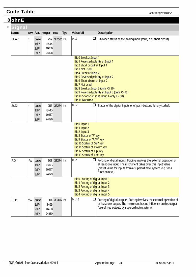
ohnE8SignalName Adr. Integer realr/w Typ Value/off Description
Bit-coded status of the analog input (fault, e.g. short circuit)
Bit 0 Break at Input 1Bit 1 Reversed polarity at Input 1Bit 2 Short circuit at Input 1Bit 3 Not usedBit 4 Break at Input 2Bit 5 Reversed polarity at Input 2Bit 6 Short-circuit at Input 2Bit 7 Not usedBit 8 Break at Input 3 (only KS 90)Bit 9 Reversed polarity at Input 3 (only KS 90)Bit 10 Short-circuit at Input 3 (only KS 90)Bit 11 Not used
St.Ain8444
1663624828
33272r Int 0...7252base1dP2dP3dP
Status of the digital inputs or of push-buttons (binary coded).
Bit 0 Input 1Bit 1 Input 2Bit 2 Input 3Bit 8 Status of 'F' keyBit 9 Status of 'A/M' keyBit 10 Status of 'Sel' keyBit 11 Status of 'Down' keyBit 12 Status of 'Up' keyBit 13 Status of 'Loc' key
St.Di8445
1663724829
33274r Int 0...7253base1dP2dP3dP
Forcing of digital inputs. Forcing involves the external operation ofat least one input. The instrument takes over this input value(preset value for inputs from a superordinate system, e.g. for afunction test.)
Bit 0 Forcing of digital input 1Bit 1 Forcing of digital input 2Bit 2 Forcing of digital input 3Bit 3 Forcing of digital input 4Bit 4 Forcing of digital input 5
F.Di8495
1668724879
33374r/w Int 0...1303base1dP2dP3dP
Forcing of digital outputs. Forcing involves the external operation ofat least one output. The instrument has no influence on this output(use of free outputs by superordinate system).
F.Do8496
1668824880
33376r/w Int 0...15304base1dP2dP3dP
Code Table Operating Version2
Appendix Page 24PMA GmbH - Interfacedescription KS40-1 9499 040 63511
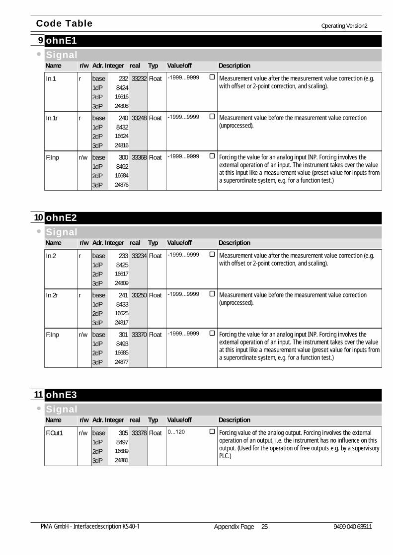
ohnE19SignalName Adr. Integer realr/w Typ Value/off Description
Measurement value after the measurement value correction (e.g.with offset or 2-point correction, and scaling).
In.18424
1661624808
33232r Float -1999...9999232base1dP2dP3dP
Measurement value before the measurement value correction(unprocessed).
In.1r8432
1662424816
33248r Float -1999...9999240base1dP2dP3dP
Forcing the value for an analog input INP. Forcing involves theexternal operation of an input. The instrument takes over the valueat this input like a measurement value (preset value for inputs froma superordinate system, e.g. for a function test.)
F.Inp8492
1668424876
33368r/w Float -1999...9999300base1dP2dP3dP
ohnE210SignalName Adr. Integer realr/w Typ Value/off Description
Measurement value after the measurement value correction (e.g.with offset or 2-point correction, and scaling).
In.28425
1661724809
33234r Float -1999...9999233base1dP2dP3dP
Measurement value before the measurement value correction(unprocessed).
In.2r8433
1662524817
33250r Float -1999...9999241base1dP2dP3dP
Forcing the value for an analog input INP. Forcing involves theexternal operation of an input. The instrument takes over the valueat this input like a measurement value (preset value for inputs froma superordinate system, e.g. for a function test.)
F.Inp8493
1668524877
33370r/w Float -1999...9999301base1dP2dP3dP
ohnE311SignalName Adr. Integer realr/w Typ Value/off Description
Forcing value of the analog output. Forcing involves the externaloperation of an output, i.e. the instrument has no influence on thisoutput. (Used for the operation of free outputs e.g. by a supervisoryPLC.)
F.Out18497
1668924881
33378r/w Float 0...120305base1dP2dP3dP
Code Table Operating Version2
Appendix Page 25PMA GmbH - Interfacedescription KS40-1 9499 040 63511
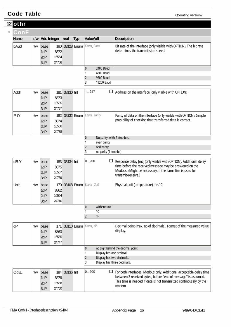
othr12ConFName Adr. Integer realr/w Typ Value/off Description
Enum_Baud Bit rate of the interface (only visible with OPTION). The bit ratedetermines the transmission speed.
bAud8372
1656424756
33128r/w Enum180base1dP2dP3dP
0 2400 Baud1 4800 Baud2 9600 Baud3 19200 Baud
Address on the interface (only visible with OPTION)Addr8373
1656524757
33130r/w Int 1...247181base1dP2dP3dP
Enum_Parity Parity of data on the interface (only visible with OPTION). Simplepossibility of checking that transferred data is correct.
PrtY8374
1656624758
33132r/w Enum182base1dP2dP3dP
0 No parity, with 2 stop bits.1 even parity2 odd parity3 no parity (1 stop bit)
Response delay [ms] (only visible with OPTION). Additional delaytime before the received message may be answered on theModbus. (Might be necessary, if the same line is used fortransmit/receive.)
dELY8375
1656724759
33134r/w Int 0...200183base1dP2dP3dP
Enum_Unit Physical unit (temperature), f.e.°CUnit8362
1655424746
33108r/w Enum170base1dP2dP3dP
0 without unit1 °C2 °F
Enum_dP Decimal point (max. no of decimals). Format of the measured valuedisplay.
dP8363
1655524747
33110r/w Enum171base1dP2dP3dP
0 no digit behind the decimal point1 Display has one decimal.2 Display has two decimals.3 Display has three decimals.
For both interfaces, Modbus only. Additional acceptable delay timebetween 2 received bytes, before "end of message" is assumed.This time is needed if data is not transmitted continousely by themodem.
C.dEL8376
1656824760
33136r/w Int 0...200184base1dP2dP3dP
Code Table Operating Version2
Appendix Page 26PMA GmbH - Interfacedescription KS40-1 9499 040 63511
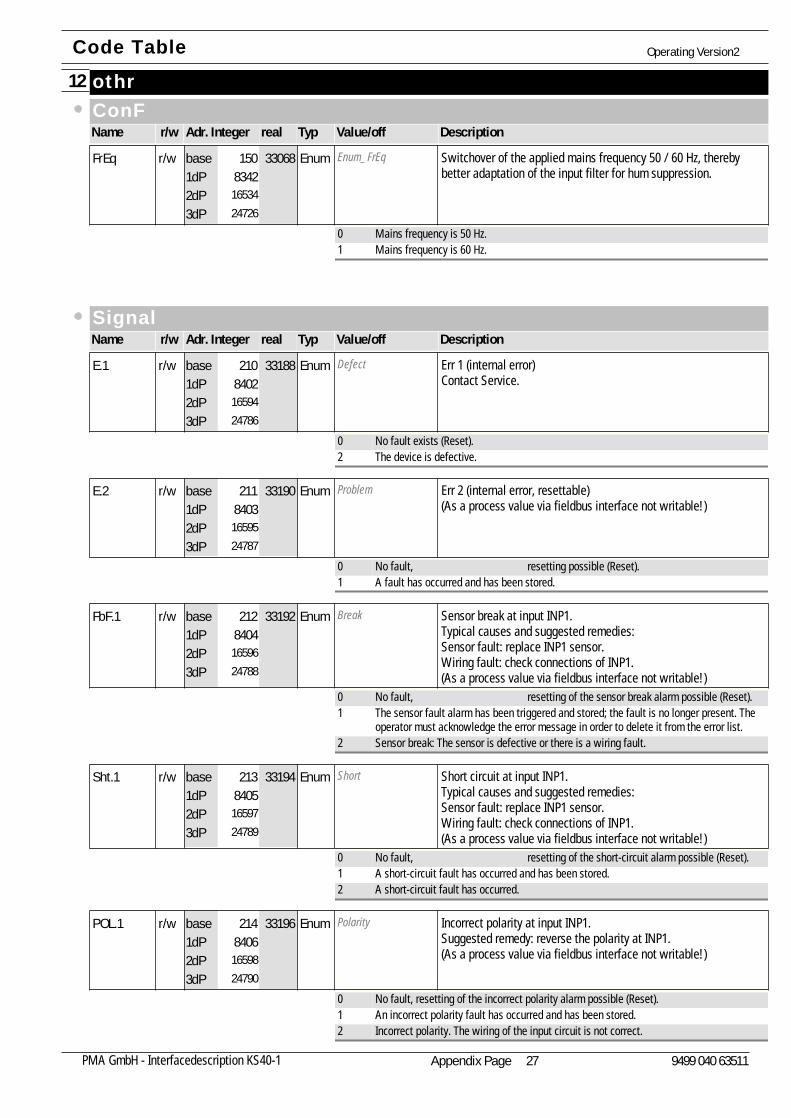
othr12ConFName Adr. Integer realr/w Typ Value/off Description
Enum_FrEq Switchover of the applied mains frequency 50 / 60 Hz, therebybetter adaptation of the input filter for hum suppression.
FrEq8342
1653424726
33068r/w Enum150base1dP2dP3dP
0 Mains frequency is 50 Hz.1 Mains frequency is 60 Hz.
SignalName Adr. Integer realr/w Typ Value/off Description
Defect Err 1 (internal error)Contact Service.
E.18402
1659424786
33188r/w Enum210base1dP2dP3dP
0 No fault exists (Reset).2 The device is defective.
Problem Err 2 (internal error, resettable)(As a process value via fieldbus interface not writable!)
E.28403
1659524787
33190r/w Enum211base1dP2dP3dP
0 No fault, resetting possible (Reset).1 A fault has occurred and has been stored.
Break Sensor break at input INP1.Typical causes and suggested remedies:Sensor fault: replace INP1 sensor.Wiring fault: check connections of INP1.(As a process value via fieldbus interface not writable!)
FbF.18404
1659624788
33192r/w Enum212base1dP2dP3dP
0 No fault, resetting of the sensor break alarm possible (Reset).1 The sensor fault alarm has been triggered and stored; the fault is no longer present. The
operator must acknowledge the error message in order to delete it from the error list.2 Sensor break: The sensor is defective or there is a wiring fault.
Short Short circuit at input INP1.Typical causes and suggested remedies:Sensor fault: replace INP1 sensor.Wiring fault: check connections of INP1.(As a process value via fieldbus interface not writable!)
Sht.18405
1659724789
33194r/w Enum213base1dP2dP3dP
0 No fault, resetting of the short-circuit alarm possible (Reset).1 A short-circuit fault has occurred and has been stored.2 A short-circuit fault has occurred.
Polarity Incorrect polarity at input INP1.Suggested remedy: reverse the polarity at INP1.(As a process value via fieldbus interface not writable!)
POL.18406
1659824790
33196r/w Enum214base1dP2dP3dP
0 No fault, resetting of the incorrect polarity alarm possible (Reset).1 An incorrect polarity fault has occurred and has been stored.2 Incorrect polarity. The wiring of the input circuit is not correct.
Code Table Operating Version2
Appendix Page 27PMA GmbH - Interfacedescription KS40-1 9499 040 63511
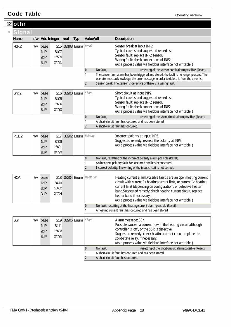
othr12SignalName Adr. Integer realr/w Typ Value/off Description
Break Sensor break at input INP2.Typical causes and suggested remedies:Sensor fault: replace INP2 sensor.Wiring fault: check connections of INP2.(As a process value via fieldbus interface not writable!)
FbF.28407
1659924791
33198r/w Enum215base1dP2dP3dP
0 No fault, resetting of the sensor break alarm possible (Reset).1 The sensor fault alarm has been triggered and stored; the fault is no longer present. The
operator must acknowledge the error message in order to delete it from the error list.2 Sensor break: The sensor is defective or there is a wiring fault.
Short Short circuit at input INP2.Typical causes and suggested remedies:Sensor fault: replace INP2 sensor.Wiring fault: check connections of INP2.(As a process value via fieldbus interface not writable!)
Sht.28408
1660024792
33200r/w Enum216base1dP2dP3dP
0 No fault, resetting of the short-circuit alarm possible (Reset).1 A short-circuit fault has occurred and has been stored.2 A short-circuit fault has occurred.
Polarity Incorrect polarity at input INP2.Suggested remedy: reverse the polarity at INP2.(As a process value via fieldbus interface not writable!)
POL.28409
1660124793
33202r/w Enum217base1dP2dP3dP
0 No fault, resetting of the incorrect polarity alarm possible (Reset).1 An incorrect polarity fault has occurred and has been stored.2 Incorrect polarity. The wiring of the input circuit is not correct.
HeatCurr Heating current alarm.Possible fault s are an open heating currentcircuit with current I < heating current limit, or current I > heatingcurrent limit (depending on configuration), or defective heaterband.Suggested remedy: check heating current circuit, replaceheater band if necessary.(As a process value via fieldbus interface not writable!)
HCA8410
1660224794
33204r/w Enum218base1dP2dP3dP
0 No fault, resetting of the heating current alarm possible (Reset).1 A heating current fault has occurred and has been stored.
Short Alarm message: SSrPossible causes: a current flow in the heating circuit althoughcontroller is 'off', or the SSR is defective.Suggested remedy: check heating current circuit, replace thesolid-state relay, if necessary.(As a process value via fieldbus interface not writable!)
SSr8411
1660324795
33206r/w Enum219base1dP2dP3dP
0 No fault, resetting of the short-circuit alarm possible (Reset).1 A short-circuit fault has occurred and has been stored.2 A short-circuit fault has occurred.
Code Table Operating Version2
Appendix Page 28PMA GmbH - Interfacedescription KS40-1 9499 040 63511
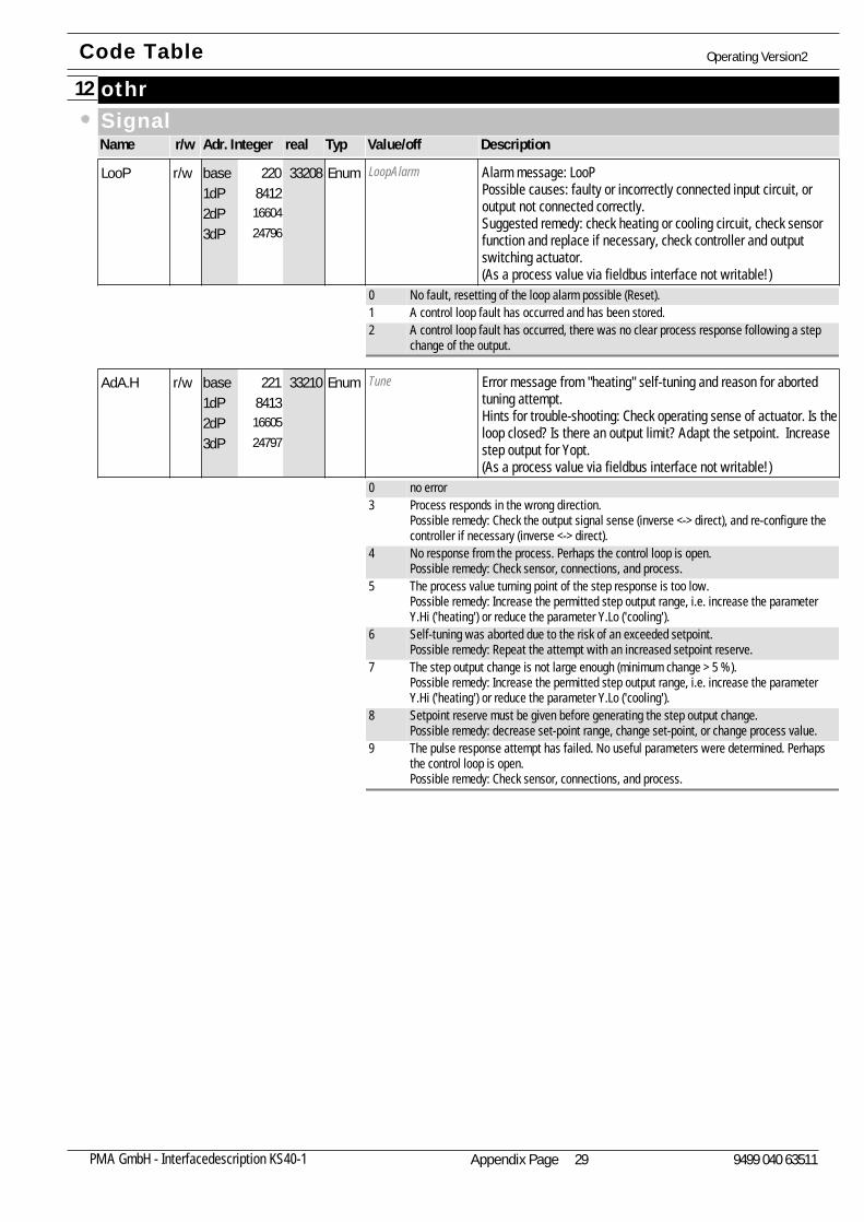
othr12SignalName Adr. Integer realr/w Typ Value/off Description
LoopAlarm Alarm message: LooPPossible causes: faulty or incorrectly connected input circuit, oroutput not connected correctly.Suggested remedy: check heating or cooling circuit, check sensorfunction and replace if necessary, check controller and outputswitching actuator.(As a process value via fieldbus interface not writable!)
LooP8412
1660424796
33208r/w Enum220base1dP2dP3dP
0 No fault, resetting of the loop alarm possible (Reset).1 A control loop fault has occurred and has been stored.2 A control loop fault has occurred, there was no clear process response following a step
change of the output.
Tune Error message from "heating" self-tuning and reason for abortedtuning attempt.Hints for trouble-shooting: Check operating sense of actuator. Is theloop closed? Is there an output limit? Adapt the setpoint. Increasestep output for Yopt.(As a process value via fieldbus interface not writable!)
AdA.H8413
1660524797
33210r/w Enum221base1dP2dP3dP
0 no error3 Process responds in the wrong direction.
Possible remedy: Check the output signal sense (inverse <-> direct), and re-configure thecontroller if necessary (inverse <-> direct).
4 No response from the process. Perhaps the control loop is open.Possible remedy: Check sensor, connections, and process.
5 The process value turning point of the step response is too low.Possible remedy: Increase the permitted step output range, i.e. increase the parameterY.Hi ('heating') or reduce the parameter Y.Lo ('cooling').
6 Self-tuning was aborted due to the risk of an exceeded setpoint.Possible remedy: Repeat the attempt with an increased setpoint reserve.
7 The step output change is not large enough (minimum change > 5 %).Possible remedy: Increase the permitted step output range, i.e. increase the parameterY.Hi ('heating') or reduce the parameter Y.Lo ('cooling').
8 Setpoint reserve must be given before generating the step output change.Possible remedy: decrease set-point range, change set-point, or change process value.
9 The pulse response attempt has failed. No useful parameters were determined. Perhapsthe control loop is open.Possible remedy: Check sensor, connections, and process.
Code Table Operating Version2
Appendix Page 29PMA GmbH - Interfacedescription KS40-1 9499 040 63511
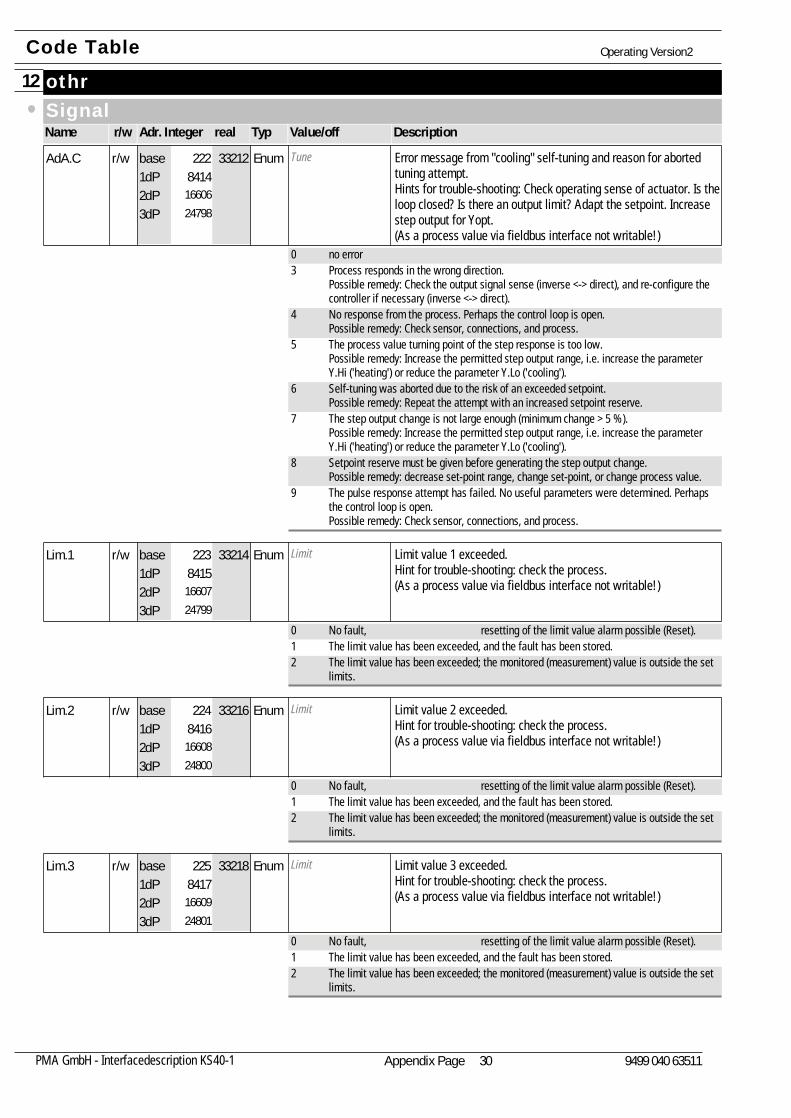
othr12SignalName Adr. Integer realr/w Typ Value/off Description
Tune Error message from "cooling" self-tuning and reason for abortedtuning attempt.Hints for trouble-shooting: Check operating sense of actuator. Is theloop closed? Is there an output limit? Adapt the setpoint. Increasestep output for Yopt.(As a process value via fieldbus interface not writable!)
AdA.C8414
1660624798
33212r/w Enum222base1dP2dP3dP
0 no error3 Process responds in the wrong direction.
Possible remedy: Check the output signal sense (inverse <-> direct), and re-configure thecontroller if necessary (inverse <-> direct).
4 No response from the process. Perhaps the control loop is open.Possible remedy: Check sensor, connections, and process.
5 The process value turning point of the step response is too low.Possible remedy: Increase the permitted step output range, i.e. increase the parameterY.Hi ('heating') or reduce the parameter Y.Lo ('cooling').
6 Self-tuning was aborted due to the risk of an exceeded setpoint.Possible remedy: Repeat the attempt with an increased setpoint reserve.
7 The step output change is not large enough (minimum change > 5 %).Possible remedy: Increase the permitted step output range, i.e. increase the parameterY.Hi ('heating') or reduce the parameter Y.Lo ('cooling').
8 Setpoint reserve must be given before generating the step output change.Possible remedy: decrease set-point range, change set-point, or change process value.
9 The pulse response attempt has failed. No useful parameters were determined. Perhapsthe control loop is open.Possible remedy: Check sensor, connections, and process.
Limit Limit value 1 exceeded.Hint for trouble-shooting: check the process.(As a process value via fieldbus interface not writable!)
Lim.18415
1660724799
33214r/w Enum223base1dP2dP3dP
0 No fault, resetting of the limit value alarm possible (Reset).1 The limit value has been exceeded, and the fault has been stored.2 The limit value has been exceeded; the monitored (measurement) value is outside the set
limits.
Limit Limit value 2 exceeded.Hint for trouble-shooting: check the process.(As a process value via fieldbus interface not writable!)
Lim.28416
1660824800
33216r/w Enum224base1dP2dP3dP
0 No fault, resetting of the limit value alarm possible (Reset).1 The limit value has been exceeded, and the fault has been stored.2 The limit value has been exceeded; the monitored (measurement) value is outside the set
limits.
Limit Limit value 3 exceeded.Hint for trouble-shooting: check the process.(As a process value via fieldbus interface not writable!)
Lim.38417
1660924801
33218r/w Enum225base1dP2dP3dP
0 No fault, resetting of the limit value alarm possible (Reset).1 The limit value has been exceeded, and the fault has been stored.2 The limit value has been exceeded; the monitored (measurement) value is outside the set
limits.
Code Table Operating Version2
Appendix Page 30PMA GmbH - Interfacedescription KS40-1 9499 040 63511
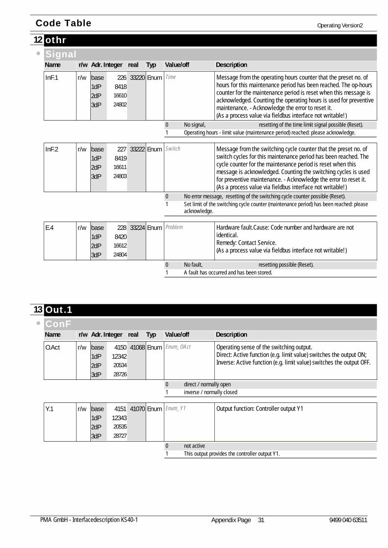
othr12SignalName Adr. Integer realr/w Typ Value/off Description
Time Message from the operating hours counter that the preset no. ofhours for this maintenance period has been reached. The op-hourscounter for the maintenance period is reset when this message isacknowledged. Counting the operating hours is used for preventivemaintenance. - Acknowledge the error to reset it.(As a process value via fieldbus interface not writable!)
InF.18418
1661024802
33220r/w Enum226base1dP2dP3dP
0 No signal, resetting of the time limit signal possible (Reset).1 Operating hours - limit value (maintenance period) reached: please acknowledge.
Switch Message from the switching cycle counter that the preset no. ofswitch cycles for this maintenance period has been reached. Thecycle counter for the maintenance period is reset when thismessage is acknowledged. Counting the switching cycles is usedfor preventive maintenance. - Acknowledge the error to reset it.(As a process value via fieldbus interface not writable!)
InF.28419
1661124803
33222r/w Enum227base1dP2dP3dP
0 No error message, resetting of the switching cycle counter possible (Reset).1 Set limit of the switching cycle counter (maintenance period) has been reached: please
acknowledge.
Problem Hardware fault.Cause: Code number and hardware are notidentical.Remedy: Contact Service.(As a process value via fieldbus interface not writable!)
E.48420
1661224804
33224r/w Enum228base1dP2dP3dP
0 No fault, resetting possible (Reset).1 A fault has occurred and has been stored.
Out.113ConFName Adr. Integer realr/w Typ Value/off Description
Enum_OAct Operating sense of the switching output.Direct: Active function (e.g. limit value) switches the output ON;Inverse: Active function (e.g. limit value) switches the output OFF.
O.Act123422053428726
41068r/w Enum4150base1dP2dP3dP
0 direct / normally open1 inverse / normally closed
Enum_Y1 Output function: Controller output Y1Y.1123432053528727
41070r/w Enum4151base1dP2dP3dP
0 not active1 This output provides the controller output Y1.
Code Table Operating Version2
Appendix Page 31PMA GmbH - Interfacedescription KS40-1 9499 040 63511
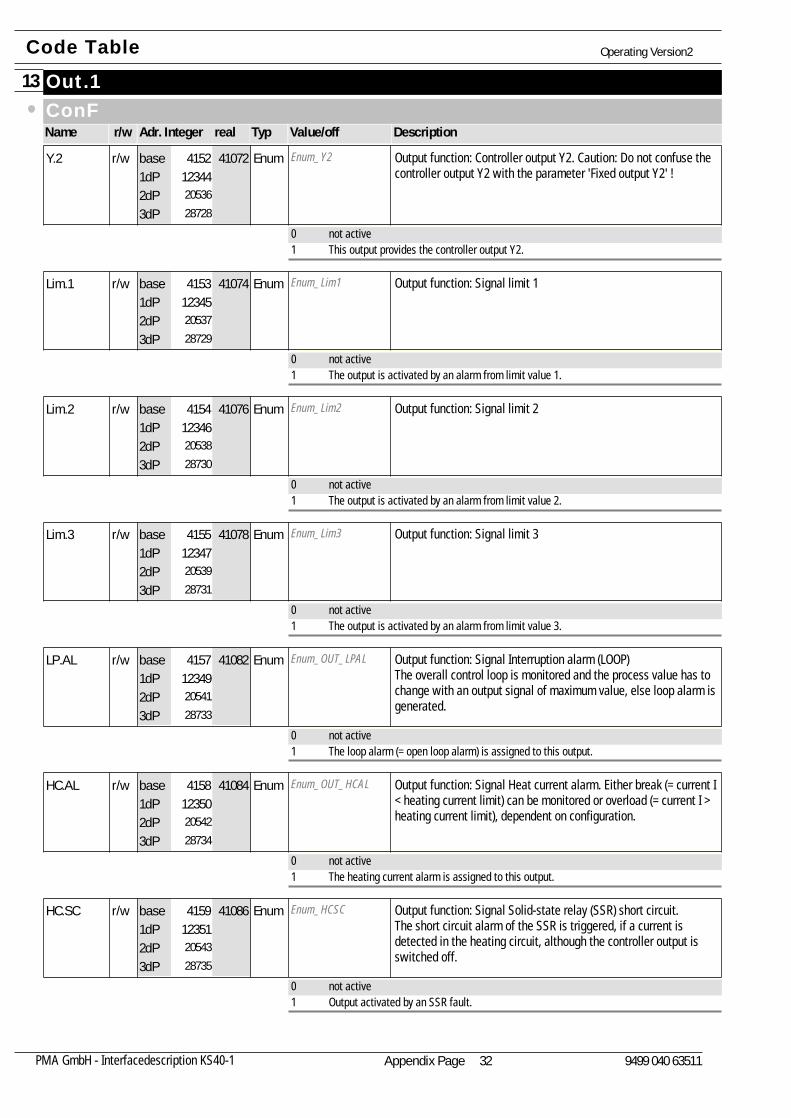
Out.113ConFName Adr. Integer realr/w Typ Value/off Description
Enum_Y2 Output function: Controller output Y2. Caution: Do not confuse thecontroller output Y2 with the parameter 'Fixed output Y2' !
Y.2123442053628728
41072r/w Enum4152base1dP2dP3dP
0 not active1 This output provides the controller output Y2.
Enum_Lim1 Output function: Signal limit 1Lim.1123452053728729
41074r/w Enum4153base1dP2dP3dP
0 not active1 The output is activated by an alarm from limit value 1.
Enum_Lim2 Output function: Signal limit 2Lim.2123462053828730
41076r/w Enum4154base1dP2dP3dP
0 not active1 The output is activated by an alarm from limit value 2.
Enum_Lim3 Output function: Signal limit 3Lim.3123472053928731
41078r/w Enum4155base1dP2dP3dP
0 not active1 The output is activated by an alarm from limit value 3.
Enum_OUT_LPAL Output function: Signal Interruption alarm (LOOP)The overall control loop is monitored and the process value has tochange with an output signal of maximum value, else loop alarm isgenerated.
LP.AL123492054128733
41082r/w Enum4157base1dP2dP3dP
0 not active1 The loop alarm (= open loop alarm) is assigned to this output.
Enum_OUT_HCAL Output function: Signal Heat current alarm. Either break (= current I< heating current limit) can be monitored or overload (= current I >heating current limit), dependent on configuration.
HC.AL123502054228734
41084r/w Enum4158base1dP2dP3dP
0 not active1 The heating current alarm is assigned to this output.
Enum_HCSC Output function: Signal Solid-state relay (SSR) short circuit.The short circuit alarm of the SSR is triggered, if a current isdetected in the heating circuit, although the controller output isswitched off.
HC.SC123512054328735
41086r/w Enum4159base1dP2dP3dP
0 not active1 Output activated by an SSR fault.
Code Table Operating Version2
Appendix Page 32PMA GmbH - Interfacedescription KS40-1 9499 040 63511

Out.113ConFName Adr. Integer realr/w Typ Value/off Description
Enum_time Output function: Signal Timer running.This message is generated by the setpoint processing, if a timermode has been configured, and the time has elapsed.
timE123522054428736
41088r/w Enum4160base1dP2dP3dP
0 not active1 activated
Enum_TEnd Output function: Signal Timer end. This message is available when the timer has been completed (onlywhen configured as a timer).
t.End123682056028752
41120r/w Enum4176base1dP2dP3dP
0 not active1 This output is activated by the message 'Timer end'.
Enum_PEnd Output function: Signal Program end. This message is available when the program has been completed(only when configured as a program controller).
P.End123532054528737
41090r/w Enum4161base1dP2dP3dP
0 not active1 This output is activated by the message 'Program end'.
Enum_FAi1 Output function: Signal INP1 fault.The fail signal is generated, if a fault occurs at the analog InputINP1.
FAi.1123542054628738
41092r/w Enum4162base1dP2dP3dP
0 not active1 The output sends the error message 'INP1 fault'.
Enum_FAi2 Output function: Signal INP2 fault.The fail signal is generated, if a fault occurs at the analog InputINP2.
FAi.2123552054728739
41094r/w Enum4163base1dP2dP3dP
0 not active1 The output sends the error message 'INP2 fault'.
SignalName Adr. Integer realr/w Typ Value/off Description
Enum_Ausgang Status of the digital outputOut1123722056428756
41128r Enum4180base1dP2dP3dP
0 off1 on
Code Table Operating Version2
Appendix Page 33PMA GmbH - Interfacedescription KS40-1 9499 040 63511
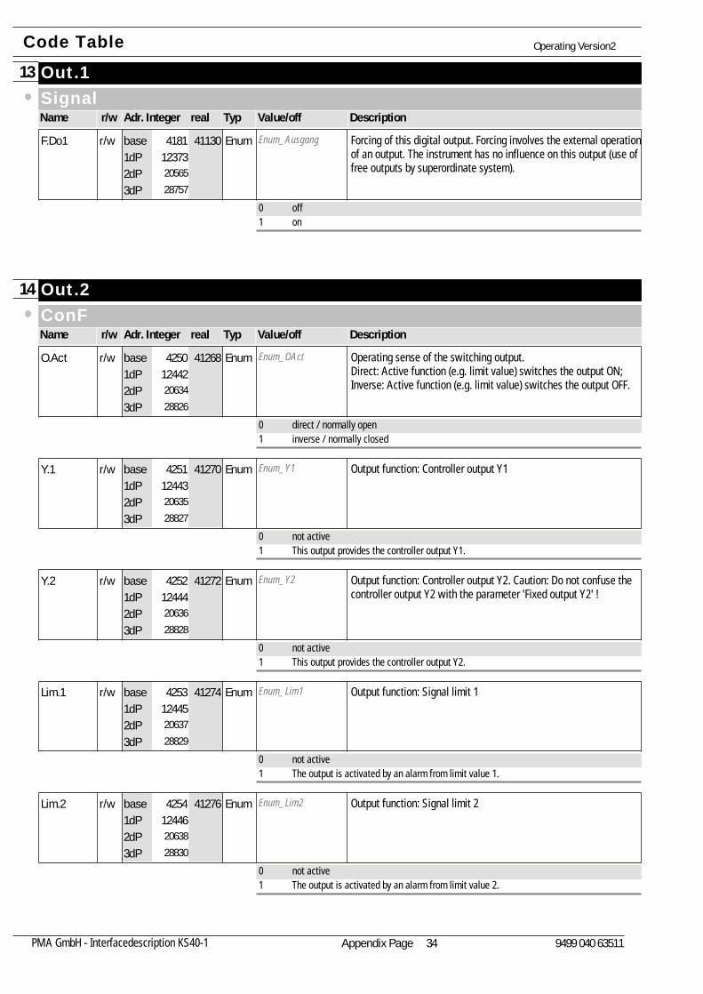
Out.113SignalName Adr. Integer realr/w Typ Value/off Description
Enum_Ausgang Forcing of this digital output. Forcing involves the external operationof an output. The instrument has no influence on this output (use offree outputs by superordinate system).
F.Do1123732056528757
41130r/w Enum4181base1dP2dP3dP
0 off1 on
Out.214ConFName Adr. Integer realr/w Typ Value/off Description
Enum_OAct Operating sense of the switching output.Direct: Active function (e.g. limit value) switches the output ON;Inverse: Active function (e.g. limit value) switches the output OFF.
O.Act124422063428826
41268r/w Enum4250base1dP2dP3dP
0 direct / normally open1 inverse / normally closed
Enum_Y1 Output function: Controller output Y1Y.1124432063528827
41270r/w Enum4251base1dP2dP3dP
0 not active1 This output provides the controller output Y1.
Enum_Y2 Output function: Controller output Y2. Caution: Do not confuse thecontroller output Y2 with the parameter 'Fixed output Y2' !
Y.2124442063628828
41272r/w Enum4252base1dP2dP3dP
0 not active1 This output provides the controller output Y2.
Enum_Lim1 Output function: Signal limit 1Lim.1124452063728829
41274r/w Enum4253base1dP2dP3dP
0 not active1 The output is activated by an alarm from limit value 1.
Enum_Lim2 Output function: Signal limit 2Lim.2124462063828830
41276r/w Enum4254base1dP2dP3dP
0 not active1 The output is activated by an alarm from limit value 2.
Code Table Operating Version2
Appendix Page 34PMA GmbH - Interfacedescription KS40-1 9499 040 63511

Out.214ConFName Adr. Integer realr/w Typ Value/off Description
Enum_Lim3 Output function: Signal limit 3Lim.3124472063928831
41278r/w Enum4255base1dP2dP3dP
0 not active1 The output is activated by an alarm from limit value 3.
Enum_OUT_LPAL Output function: Signal Interruption alarm (LOOP)The overall control loop is monitored and the process value has tochange with an output signal of maximum value, else loop alarm isgenerated.
LP.AL124492064128833
41282r/w Enum4257base1dP2dP3dP
0 not active1 The loop alarm (= open loop alarm) is assigned to this output.
Enum_OUT_HCAL Output function: Signal Heat current alarm. Either break (= current I< heating current limit) can be monitored or overload (= current I >heating current limit), dependent on configuration.
HC.AL124502064228834
41284r/w Enum4258base1dP2dP3dP
0 not active1 The heating current alarm is assigned to this output.
Enum_HCSC Output function: Signal Solid-state relay (SSR) short circuit.The short circuit alarm of the SSR is triggered, if a current isdetected in the heating circuit, although the controller output isswitched off.
HC.SC124512064328835
41286r/w Enum4259base1dP2dP3dP
0 not active1 Output activated by an SSR fault.
Enum_time Output function: Signal Timer running.This message is generated by the setpoint processing, if a timermode has been configured, and the time has elapsed.
timE124522064428836
41288r/w Enum4260base1dP2dP3dP
0 not active1 activated
Enum_TEnd Output function: Signal Timer end. This message is available when the timer has been completed (onlywhen configured as a timer).
t.End124682066028852
41320writ Enum4276base1dP2dP3dP
0 not active1 This output is activated by the message 'Timer end'.
Enum_PEnd Output function: Signal Program end. This message is available when the program has been completed(only when configured as a program controller).
P.End124532064528837
41290r/w Enum4261base1dP2dP3dP
0 not active1 This output is activated by the message 'Program end'.
Code Table Operating Version2
Appendix Page 35PMA GmbH - Interfacedescription KS40-1 9499 040 63511
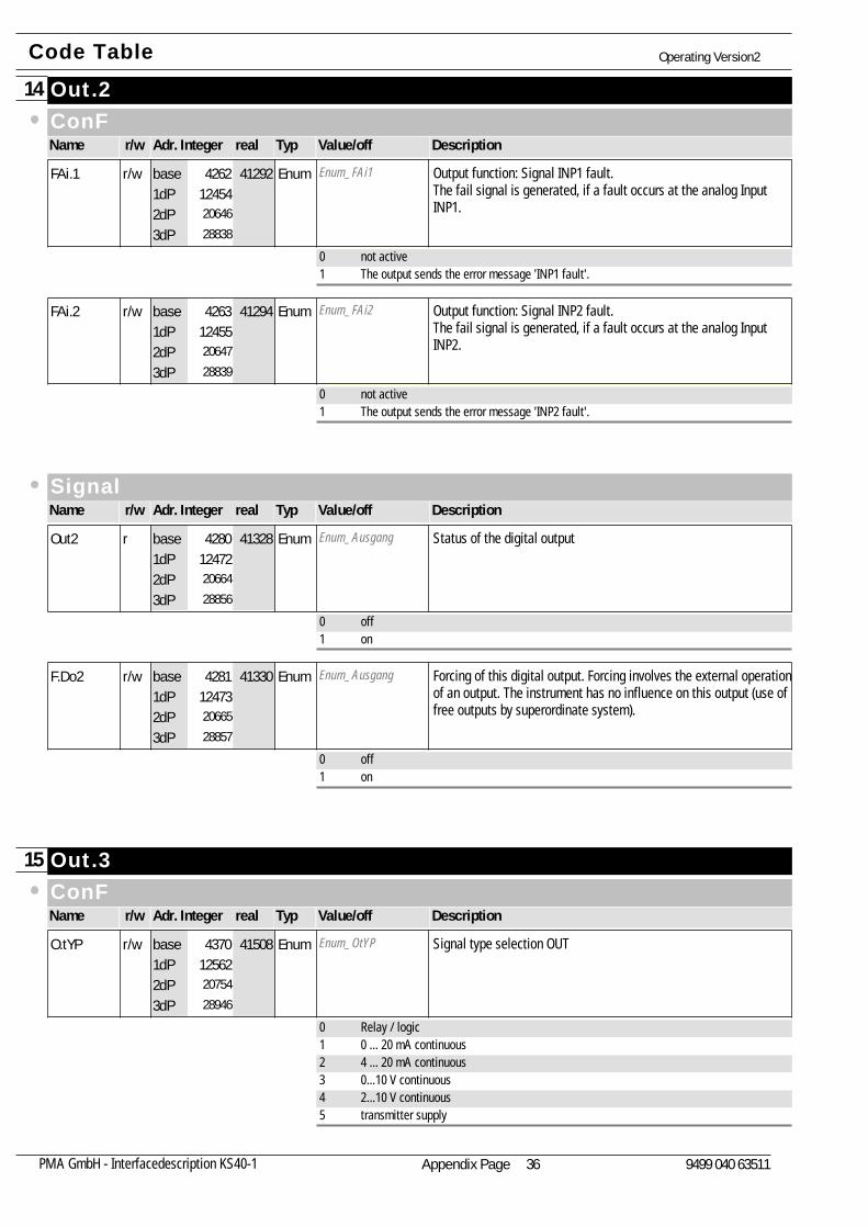
Out.214ConFName Adr. Integer realr/w Typ Value/off Description
Enum_FAi1 Output function: Signal INP1 fault.The fail signal is generated, if a fault occurs at the analog InputINP1.
FAi.1124542064628838
41292r/w Enum4262base1dP2dP3dP
0 not active1 The output sends the error message 'INP1 fault'.
Enum_FAi2 Output function: Signal INP2 fault.The fail signal is generated, if a fault occurs at the analog InputINP2.
FAi.2124552064728839
41294r/w Enum4263base1dP2dP3dP
0 not active1 The output sends the error message 'INP2 fault'.
SignalName Adr. Integer realr/w Typ Value/off Description
Enum_Ausgang Status of the digital outputOut2124722066428856
41328r Enum4280base1dP2dP3dP
0 off1 on
Enum_Ausgang Forcing of this digital output. Forcing involves the external operationof an output. The instrument has no influence on this output (use offree outputs by superordinate system).
F.Do2124732066528857
41330r/w Enum4281base1dP2dP3dP
0 off1 on
Out.315ConFName Adr. Integer realr/w Typ Value/off Description
Enum_OtYP Signal type selection OUTO.tYP125622075428946
41508r/w Enum4370base1dP2dP3dP
0 Relay / logic1 0 ... 20 mA continuous2 4 ... 20 mA continuous3 0...10 V continuous4 2...10 V continuous5 transmitter supply
Code Table Operating Version2
Appendix Page 36PMA GmbH - Interfacedescription KS40-1 9499 040 63511
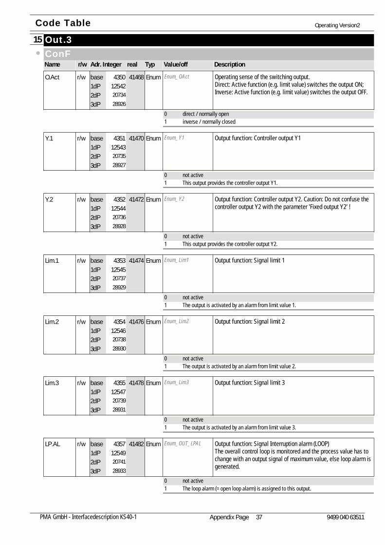
Out.315ConFName Adr. Integer realr/w Typ Value/off Description
Enum_OAct Operating sense of the switching output.Direct: Active function (e.g. limit value) switches the output ON;Inverse: Active function (e.g. limit value) switches the output OFF.
O.Act125422073428926
41468r/w Enum4350base1dP2dP3dP
0 direct / normally open1 inverse / normally closed
Enum_Y1 Output function: Controller output Y1Y.1125432073528927
41470r/w Enum4351base1dP2dP3dP
0 not active1 This output provides the controller output Y1.
Enum_Y2 Output function: Controller output Y2. Caution: Do not confuse thecontroller output Y2 with the parameter 'Fixed output Y2' !
Y.2125442073628928
41472r/w Enum4352base1dP2dP3dP
0 not active1 This output provides the controller output Y2.
Enum_Lim1 Output function: Signal limit 1Lim.1125452073728929
41474r/w Enum4353base1dP2dP3dP
0 not active1 The output is activated by an alarm from limit value 1.
Enum_Lim2 Output function: Signal limit 2Lim.2125462073828930
41476r/w Enum4354base1dP2dP3dP
0 not active1 The output is activated by an alarm from limit value 2.
Enum_Lim3 Output function: Signal limit 3Lim.3125472073928931
41478r/w Enum4355base1dP2dP3dP
0 not active1 The output is activated by an alarm from limit value 3.
Enum_OUT_LPAL Output function: Signal Interruption alarm (LOOP)The overall control loop is monitored and the process value has tochange with an output signal of maximum value, else loop alarm isgenerated.
LP.AL125492074128933
41482r/w Enum4357base1dP2dP3dP
0 not active1 The loop alarm (= open loop alarm) is assigned to this output.
Code Table Operating Version2
Appendix Page 37PMA GmbH - Interfacedescription KS40-1 9499 040 63511
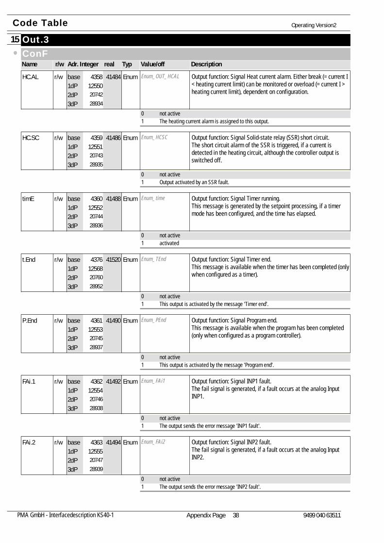
Out.315ConFName Adr. Integer realr/w Typ Value/off Description
Enum_OUT_HCAL Output function: Signal Heat current alarm. Either break (= current I< heating current limit) can be monitored or overload (= current I >heating current limit), dependent on configuration.
HC.AL125502074228934
41484r/w Enum4358base1dP2dP3dP
0 not active1 The heating current alarm is assigned to this output.
Enum_HCSC Output function: Signal Solid-state relay (SSR) short circuit.The short circuit alarm of the SSR is triggered, if a current isdetected in the heating circuit, although the controller output isswitched off.
HC.SC125512074328935
41486r/w Enum4359base1dP2dP3dP
0 not active1 Output activated by an SSR fault.
Enum_time Output function: Signal Timer running.This message is generated by the setpoint processing, if a timermode has been configured, and the time has elapsed.
timE125522074428936
41488r/w Enum4360base1dP2dP3dP
0 not active1 activated
Enum_TEnd Output function: Signal Timer end. This message is available when the timer has been completed (onlywhen configured as a timer).
t.End125682076028952
41520r/w Enum4376base1dP2dP3dP
0 not active1 This output is activated by the message 'Timer end'.
Enum_PEnd Output function: Signal Program end. This message is available when the program has been completed(only when configured as a program controller).
P.End125532074528937
41490r/w Enum4361base1dP2dP3dP
0 not active1 This output is activated by the message 'Program end'.
Enum_FAi1 Output function: Signal INP1 fault.The fail signal is generated, if a fault occurs at the analog InputINP1.
FAi.1125542074628938
41492r/w Enum4362base1dP2dP3dP
0 not active1 The output sends the error message 'INP1 fault'.
Enum_FAi2 Output function: Signal INP2 fault.The fail signal is generated, if a fault occurs at the analog InputINP2.
FAi.2125552074728939
41494r/w Enum4363base1dP2dP3dP
0 not active1 The output sends the error message 'INP2 fault'.
Code Table Operating Version2
Appendix Page 38PMA GmbH - Interfacedescription KS40-1 9499 040 63511
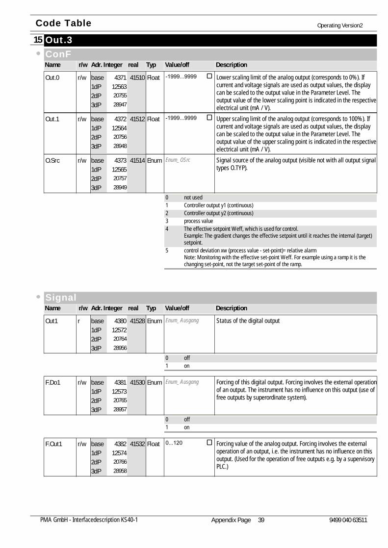
Out.315ConFName Adr. Integer realr/w Typ Value/off Description
Lower scaling limit of the analog output (corresponds to 0%). Ifcurrent and voltage signals are used as output values, the displaycan be scaled to the output value in the Parameter Level. Theoutput value of the lower scaling point is indicated in the respectiveelectrical unit (mA / V).
Out.0125632075528947
41510r/w Float -1999...99994371base1dP2dP3dP
Upper scaling limit of the analog output (corresponds to 100%). Ifcurrent and voltage signals are used as output values, the displaycan be scaled to the output value in the Parameter Level. Theoutput value of the upper scaling point is indicated in the respectiveelectrical unit (mA / V).
Out.1125642075628948
41512r/w Float -1999...99994372base1dP2dP3dP
Enum_OSrc Signal source of the analog output (visible not with all output signaltypes O.TYP).
O.Src125652075728949
41514r/w Enum4373base1dP2dP3dP
0 not used1 Controller output y1 (continuous)2 Controller output y2 (continuous)3 process value4 The effective setpoint Weff, which is used for control.
Example: The gradient changes the effective setpoint until it reaches the internal (target)setpoint.
5 control deviation xw (process value - set-point)= relative alarmNote: Monitoring with the effective set-point Weff. For example using a ramp it is thechanging set-point, not the target set-point of the ramp.
SignalName Adr. Integer realr/w Typ Value/off Description
Enum_Ausgang Status of the digital outputOut1125722076428956
41528r Enum4380base1dP2dP3dP
0 off1 on
Enum_Ausgang Forcing of this digital output. Forcing involves the external operationof an output. The instrument has no influence on this output (use offree outputs by superordinate system).
F.Do1125732076528957
41530r/w Enum4381base1dP2dP3dP
0 off1 on
Forcing value of the analog output. Forcing involves the externaloperation of an output, i.e. the instrument has no influence on thisoutput. (Used for the operation of free outputs e.g. by a supervisoryPLC.)
F.Out1125742076628958
41532r/w Float 0...1204382base1dP2dP3dP
Code Table Operating Version2
Appendix Page 39PMA GmbH - Interfacedescription KS40-1 9499 040 63511
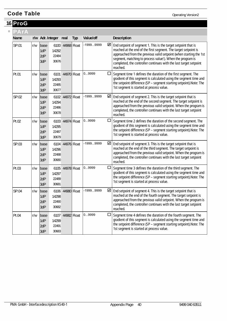
ProG16PArAName Adr. Integer realr/w Typ Value/off Description
End setpoint of segment 1. This is the target setpoint that isreached at the end of the first segment. The target setpoint isapproached from the previous valid setpoint (when starting the 1stsegment, matching to process value!). When the program iscompleted, the controller continues with the last target setpointreached.
SP.01142922248430676
44968r/w Float -1999...99996100base1dP2dP3dP
Segment time 1 defines the duration of the first segment. Thegradient of this segment is calculated using the segment time andthe setpoint difference (SP – segment starting setpoint).Note: The1st segment is started at process value.
Pt.01142932248530677
44970r/w Float 0...99996101base1dP2dP3dP
End setpoint of segment 2. This is the target setpoint that isreached at the end of the second segment. The target setpoint isapproached from the previous valid setpoint. When the program iscompleted, the controller continues with the last target setpointreached.
SP.02142942248630678
44972r/w Float -1999...99996102base1dP2dP3dP
Segment time 2 defines the duration of the second segment. Thegradient of this segment is calculated using the segment time andthe setpoint difference (SP – segment starting setpoint).Note: The1st segment is started at process value.
Pt.02142952248730679
44974r/w Float 0...99996103base1dP2dP3dP
End setpoint of segment 3. This is the target setpoint that isreached at the end of the third segment. The target setpoint isapproached from the previous valid setpoint. When the program iscompleted, the controller continues with the last target setpointreached.
SP.03142962248830680
44976r/w Float -1999...99996104base1dP2dP3dP
Segment time 3 defines the duration of the third segment. Thegradient of this segment is calculated using the segment time andthe setpoint difference (SP – segment starting setpoint).Note: The1st segment is started at process value.
Pt.03142972248930681
44978r/w Float 0...99996105base1dP2dP3dP
End setpoint of segment 4. This is the target setpoint that isreached at the end of the fourth segment. The target setpoint isapproached from the previous valid setpoint. When the program iscompleted, the controller continues with the last target setpointreached.
SP.04142982249030682
44980r/w Float -1999...99996106base1dP2dP3dP
Segment time 4 defines the duration of the fourth segment. Thegradient of this segment is calculated using the segment time andthe setpoint difference (SP – segment starting setpoint).Note: The1st segment is started at process value.
Pt.04142992249130683
44982r/w Float 0...99996107base1dP2dP3dP
Code Table Operating Version2
Appendix Page 40PMA GmbH - Interfacedescription KS40-1 9499 040 63511
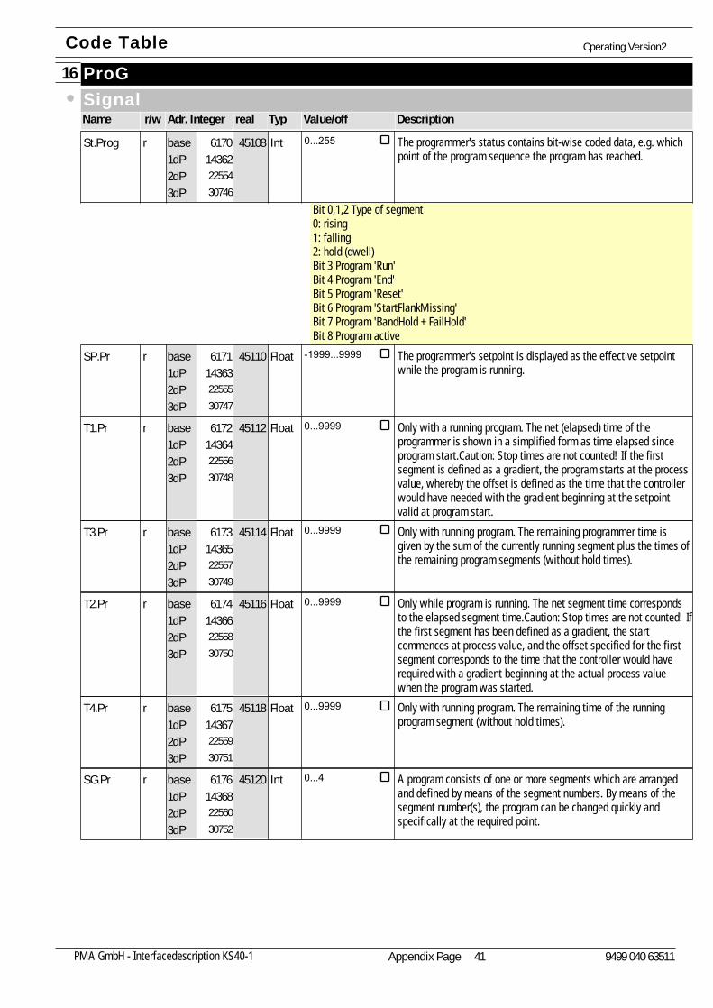
ProG16SignalName Adr. Integer realr/w Typ Value/off Description
The programmer's status contains bit-wise coded data, e.g. whichpoint of the program sequence the program has reached.
Bit 0,1,2 Type of segment0: rising1: falling2: hold (dwell)Bit 3 Program 'Run'Bit 4 Program 'End'Bit 5 Program 'Reset'Bit 6 Program 'StartFlankMissing'Bit 7 Program 'BandHold + FailHold'Bit 8 Program active
St.Prog143622255430746
45108r Int 0...2556170base1dP2dP3dP
The programmer's setpoint is displayed as the effective setpointwhile the program is running.
SP.Pr143632255530747
45110r Float -1999...99996171base1dP2dP3dP
Only with a running program. The net (elapsed) time of theprogrammer is shown in a simplified form as time elapsed sinceprogram start.Caution: Stop times are not counted! If the firstsegment is defined as a gradient, the program starts at the processvalue, whereby the offset is defined as the time that the controllerwould have needed with the gradient beginning at the setpointvalid at program start.
T1.Pr143642255630748
45112r Float 0...99996172base1dP2dP3dP
Only with running program. The remaining programmer time isgiven by the sum of the currently running segment plus the times ofthe remaining program segments (without hold times).
T3.Pr143652255730749
45114r Float 0...99996173base1dP2dP3dP
Only while program is running. The net segment time correspondsto the elapsed segment time.Caution: Stop times are not counted! Ifthe first segment has been defined as a gradient, the startcommences at process value, and the offset specified for the firstsegment corresponds to the time that the controller would haverequired with a gradient beginning at the actual process valuewhen the program was started.
T2.Pr143662255830750
45116r Float 0...99996174base1dP2dP3dP
Only with running program. The remaining time of the runningprogram segment (without hold times).
T4.Pr143672255930751
45118r Float 0...99996175base1dP2dP3dP
A program consists of one or more segments which are arrangedand defined by means of the segment numbers. By means of thesegment number(s), the program can be changed quickly andspecifically at the required point.
SG.Pr143682256030752
45120r Int 0...46176base1dP2dP3dP
Code Table Operating Version2
Appendix Page 41PMA GmbH - Interfacedescription KS40-1 9499 040 63511
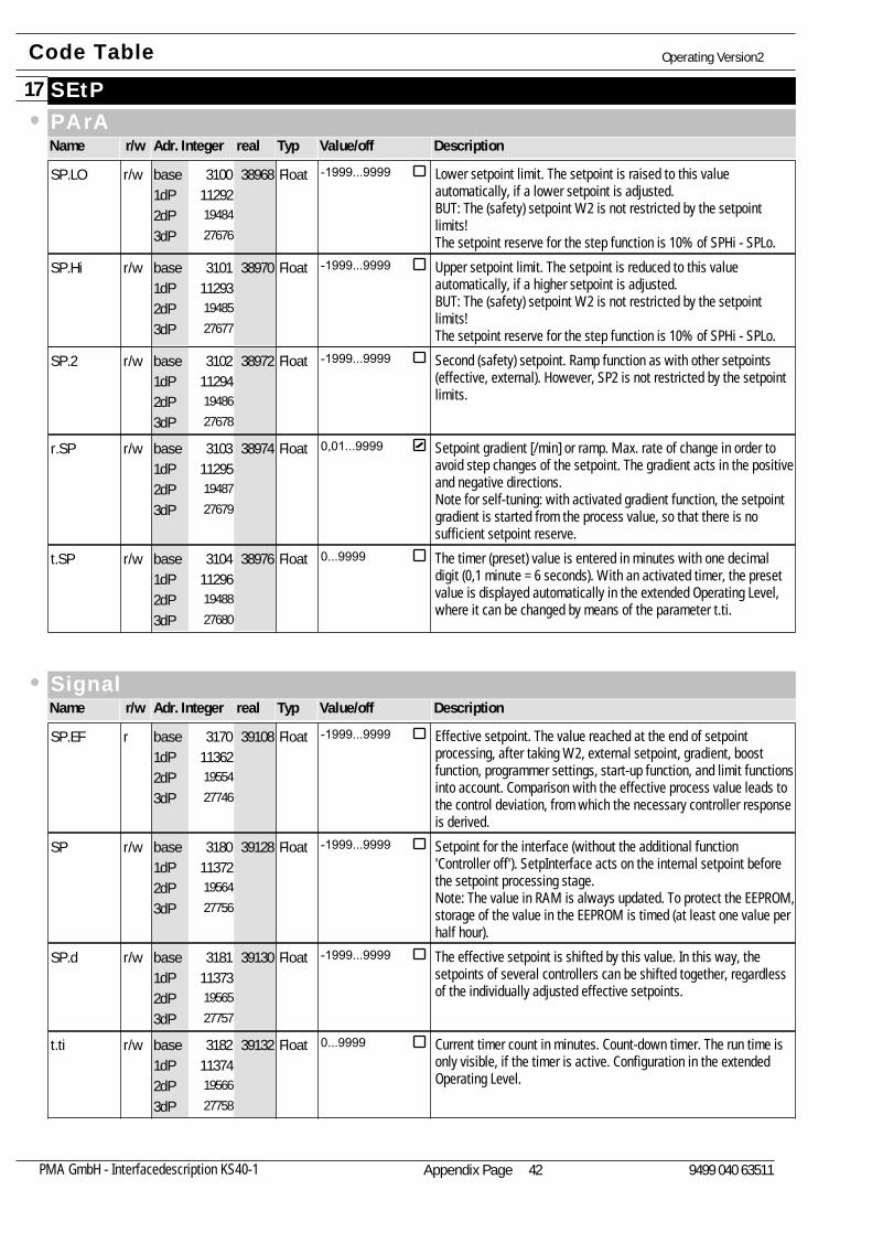
SEtP17PArAName Adr. Integer realr/w Typ Value/off Description
Lower setpoint limit. The setpoint is raised to this valueautomatically, if a lower setpoint is adjusted.BUT: The (safety) setpoint W2 is not restricted by the setpointlimits!The setpoint reserve for the step function is 10% of SPHi - SPLo.
SP.LO112921948427676
38968r/w Float -1999...99993100base1dP2dP3dP
Upper setpoint limit. The setpoint is reduced to this valueautomatically, if a higher setpoint is adjusted.BUT: The (safety) setpoint W2 is not restricted by the setpointlimits!The setpoint reserve for the step function is 10% of SPHi - SPLo.
SP.Hi112931948527677
38970r/w Float -1999...99993101base1dP2dP3dP
Second (safety) setpoint. Ramp function as with other setpoints(effective, external). However, SP2 is not restricted by the setpointlimits.
SP.2112941948627678
38972r/w Float -1999...99993102base1dP2dP3dP
Setpoint gradient [/min] or ramp. Max. rate of change in order toavoid step changes of the setpoint. The gradient acts in the positiveand negative directions.Note for self-tuning: with activated gradient function, the setpointgradient is started from the process value, so that there is nosufficient setpoint reserve.
r.SP112951948727679
38974r/w Float 0,01...99993103base1dP2dP3dP
The timer (preset) value is entered in minutes with one decimaldigit (0,1 minute = 6 seconds). With an activated timer, the presetvalue is displayed automatically in the extended Operating Level,where it can be changed by means of the parameter t.ti.
t.SP112961948827680
38976r/w Float 0...99993104base1dP2dP3dP
SignalName Adr. Integer realr/w Typ Value/off Description
Effective setpoint. The value reached at the end of setpointprocessing, after taking W2, external setpoint, gradient, boostfunction, programmer settings, start-up function, and limit functionsinto account. Comparison with the effective process value leads tothe control deviation, from which the necessary controller responseis derived.
SP.EF113621955427746
39108r Float -1999...99993170base1dP2dP3dP
Setpoint for the interface (without the additional function'Controller off'). SetpInterface acts on the internal setpoint beforethe setpoint processing stage.Note: The value in RAM is always updated. To protect the EEPROM,storage of the value in the EEPROM is timed (at least one value perhalf hour).
SP113721956427756
39128r/w Float -1999...99993180base1dP2dP3dP
The effective setpoint is shifted by this value. In this way, thesetpoints of several controllers can be shifted together, regardlessof the individually adjusted effective setpoints.
SP.d113731956527757
39130r/w Float -1999...99993181base1dP2dP3dP
Current timer count in minutes. Count-down timer. The run time isonly visible, if the timer is active. Configuration in the extendedOperating Level.
t.ti113741956627758
39132r/w Float 0...99993182base1dP2dP3dP
Code Table Operating Version2
Appendix Page 42PMA GmbH - Interfacedescription KS40-1 9499 040 63511

Tool18ConFName Adr. Integer realr/w Typ Value/off Description
Enum_Unit Engineering unit of linearization table (temperature).U.LinT8826
1701825210
34036r/w Enum634base1dP2dP3dP
0 without unit1 °C2 °F
Code Table Operating Version2
Appendix Page 43PMA GmbH - Interfacedescription KS40-1 9499 040 63511

Subject to alterations without notice © PMA Prozeß- und Maschinen-Automation GmbHÄnderungen vorbehalten P.O.B. 310 229, D-34058 Kassel, GermanySous réserve de toutes modifications Printed in Germany 9499-040-63511 (02/2005) A
4,un
ibin
d,SW
-Dru
ck,
80g2
wei
ß
9499-040-63511


![Serial Communication [Modbus Version] - Intelligent Actuator · Serial Communication [Modbus Version] Operation Manual, Tenth Edition . Modbus . Modbus Please Read Before Use Thank](https://img.pdfslide.us/doc/110x75/5eb89d6eaa14655c6b0fb9ce/serial-communication-modbus-version-intelligent-actuator-serial-communication.jpg)

![Serial Communication [Modbus Version] Operation Manual ......RCP6 (PLC Unit) ERC2, ERC3 Serial Communication [Modbus Version] Operation Manual, Ninth Edition . Modbus . Modbus Please](https://img.pdfslide.us/doc/110x75/5e6d973e9fc0481438519dec/serial-communication-modbus-version-operation-manual-rcp6-plc-unit-erc2.jpg)