Embed Size (px)
Citation preview
Kreg Jig®
HD Railing Force TestTest Results:The chart represents results from third party testing on Kreg Jig® HD Deck Railing applications. The fi rst column indicates the Joint type used. We used two common wood types of material, cedar and ACQ pressure treated wood.
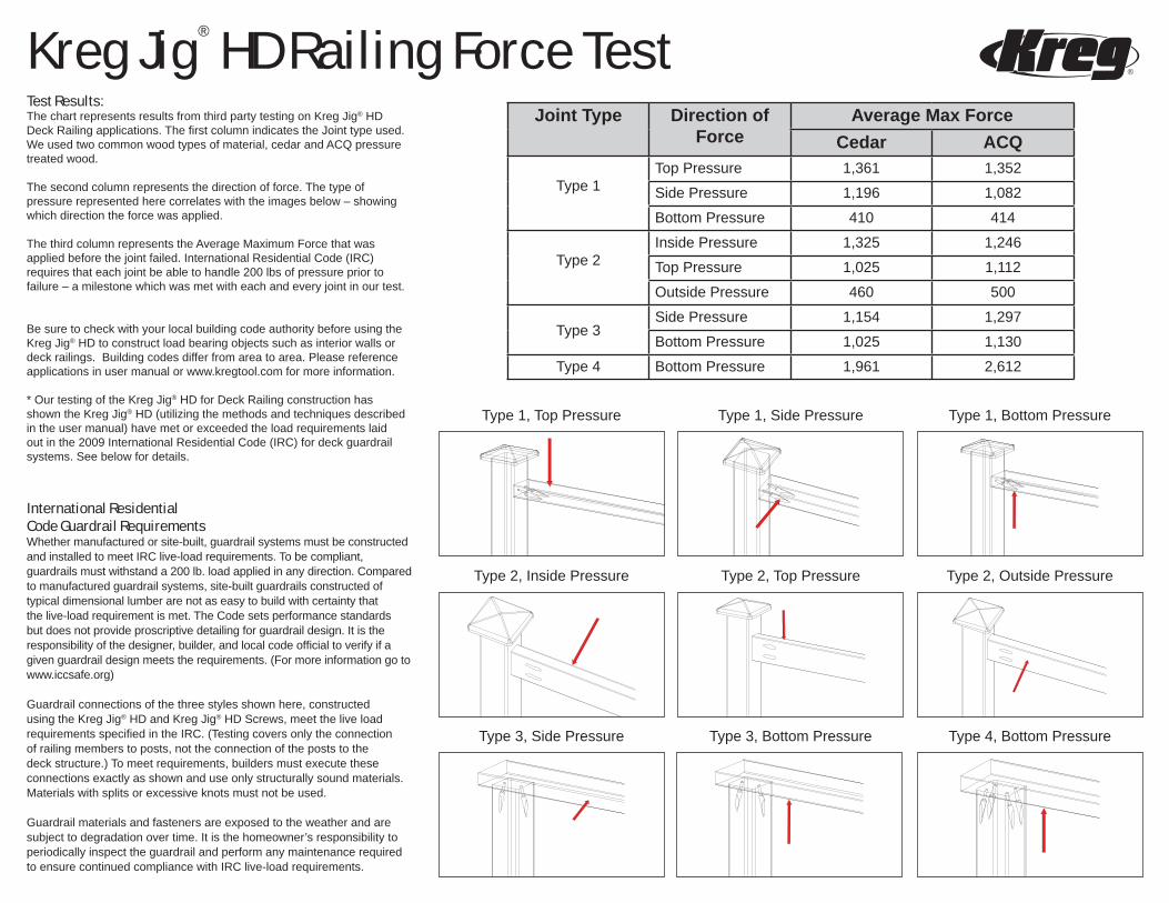
The second column represents the direction of force. The type of pressure represented here correlates with the images below – showing which direction the force was applied.
The third column represents the Average Maximum Force that was applied before the joint failed. International Residential Code (IRC) requires that each joint be able to handle 200 lbs of pressure prior to failure – a milestone which was met with each and every joint in our test.
Be sure to check with your local building code authority before using the Kreg Jig® HD to construct load bearing objects such as interior walls or deck railings. Building codes differ from area to area. Please reference applications in user manual or www.kregtool.com for more information.
* Our testing of the Kreg Jig® HD for Deck Railing construction has shown the Kreg Jig® HD (utilizing the methods and techniques described in the user manual) have met or exceeded the load requirements laid out in the 2009 International Residential Code (IRC) for deck guardrail systems. See below for details.
International ResidentialCode Guardrail RequirementsWhether manufactured or site-built, guardrail systems must be constructed and installed to meet IRC live-load requirements. To be compliant, guardrails must withstand a 200 lb. load applied in any direction. Compared to manufactured guardrail systems, site-built guardrails constructed of typical dimensional lumber are not as easy to build with certainty that the live-load requirement is met. The Code sets performance standards but does not provide proscriptive detailing for guardrail design. It is the responsibility of the designer, builder, and local code offi cial to verify if a given guardrail design meets the requirements. (For more information go to www.iccsafe.org)
Guardrail connections of the three styles shown here, constructed using the Kreg Jig® HD and Kreg Jig® HD Screws, meet the live load requirements specifi ed in the IRC. (Testing covers only the connection of railing members to posts, not the connection of the posts to the deck structure.) To meet requirements, builders must execute these connections exactly as shown and use only structurally sound materials. Materials with splits or excessive knots must not be used.
Guardrail materials and fasteners are exposed to the weather and are subject to degradation over time. It is the homeowner’s responsibility to periodically inspect the guardrail and perform any maintenance required to ensure continued compliance with IRC live-load requirements.
Joint Type Direction of Force
Average Max ForceCedar ACQ
Type 1Top Pressure 1,361 1,352
Side Pressure 1,196 1,082
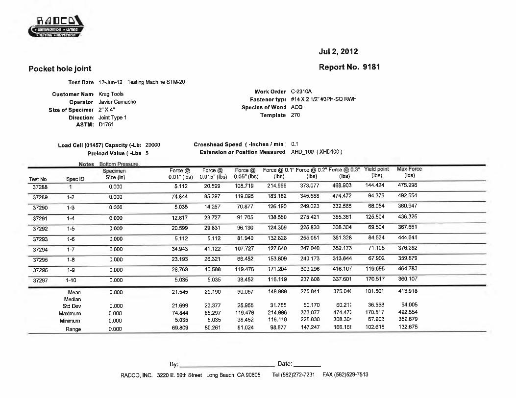
Bottom Pressure 410 414
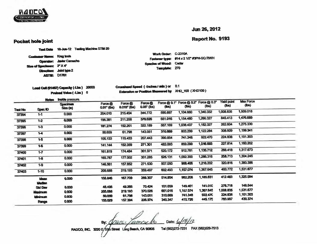
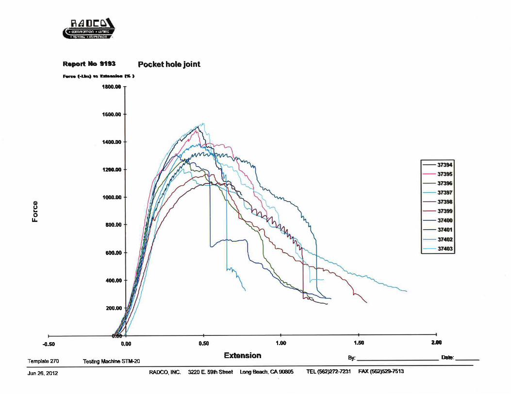
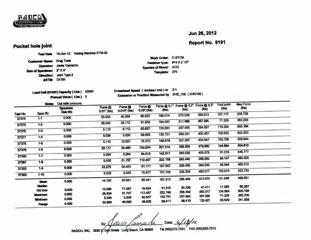
Type 2Inside Pressure 1,325 1,246
Top Pressure 1,025 1,112
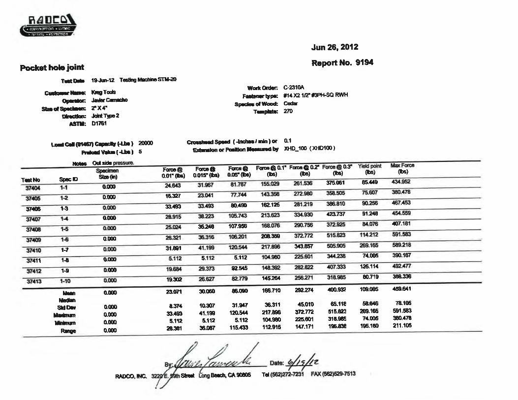
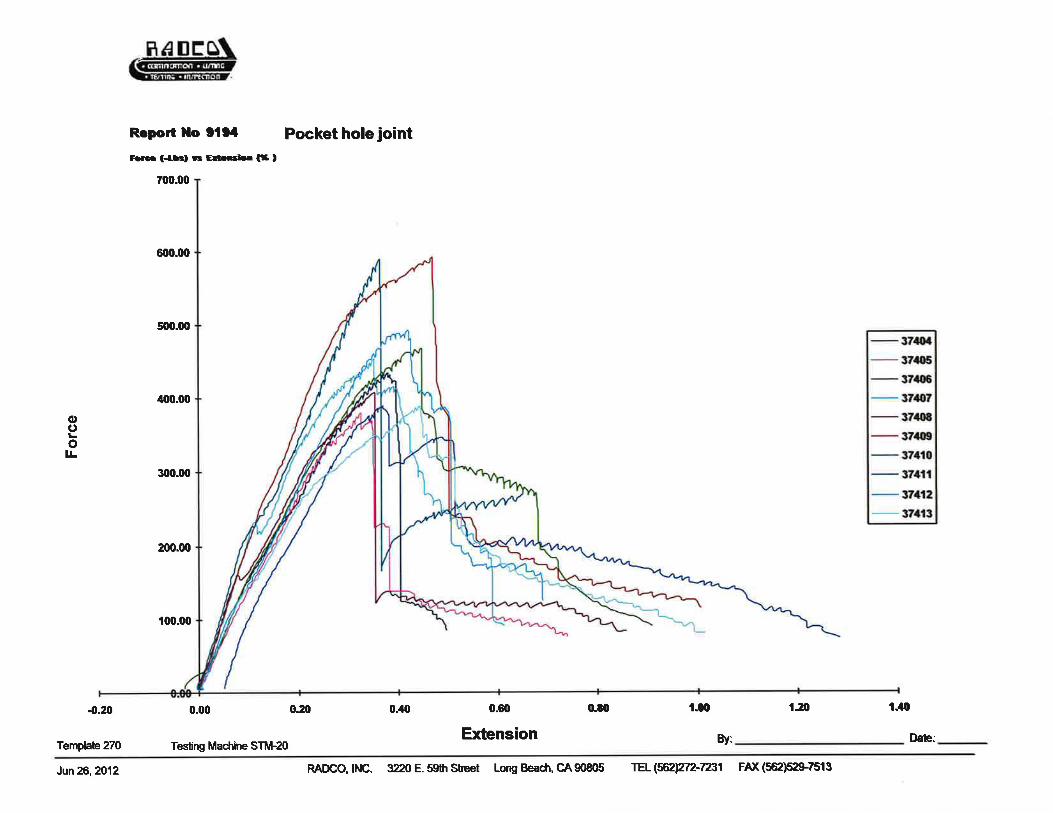
Outside Pressure 460 500
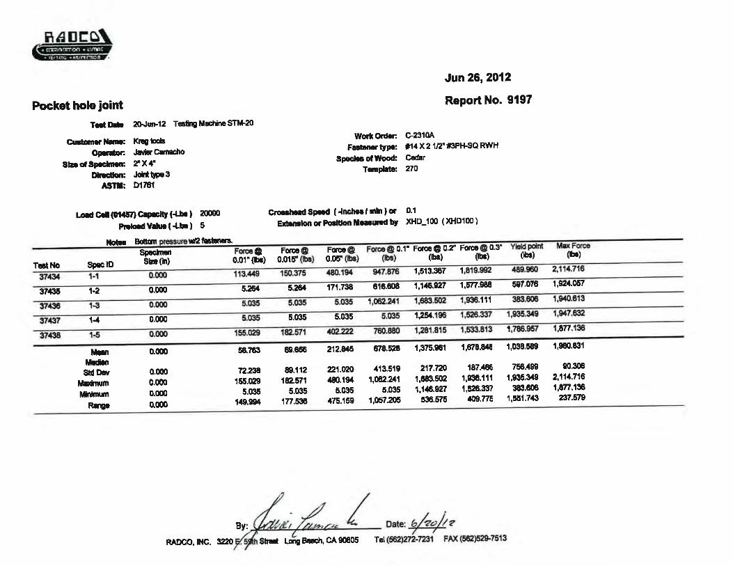
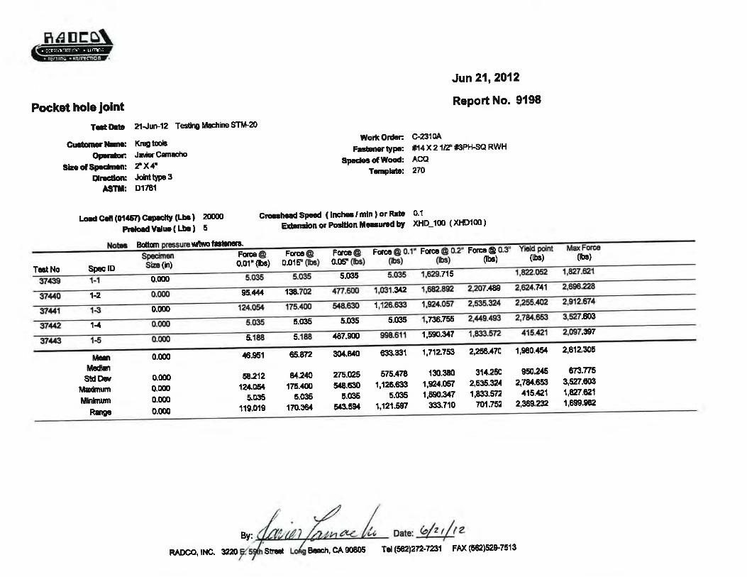
Type 3Side Pressure 1,154 1,297
Bottom Pressure 1,025 1,130
Type 4 Bottom Pressure 1,961 2,612
Type 1, Top Pressure Type 1, Side Pressure Type 1, Bottom Pressure
Type 2, Inside Pressure Type 2, Top Pressure Type 2, Outside Pressure
Type 3, Side Pressure Type 3, Bottom Pressure Type 4, Bottom Pressure
RAD-5178
ii
TABLE OF CONTENTS
1.0 INTRODUCTION . . . . . . . . . . . . . . . . . . . . . . . . . . . . . . . . . . . . . . . . . . . . . . . . . . . . . . . . . 1
2.0 MATERIAL DESCRIPTION . . . . . . . . . . . . . . . . . . . . . . . . . . . . . . . . . . . . . . . . . . . . . . . . . 1
3.0 OBJECTIVE . . . . . . . . . . . . . . . . . . . . . . . . . . . . . . . . . . . . . . . . . . . . . . . . . . . . . . . . . . . . . 1
4.0 TEST PROCEDURES & RESULTS . . . . . . . . . . . . . . . . . . . . . . . . . . . . . . . . . . . . . . . . . . . 1
5.0 PHOTOGRAPHS . . . . . . . . . . . . . . . . . . . . . . . . . . . . . . . . . . . . . . . . . . . . . . . . . . . . . . . . . 4
6.0 DRAWINGS . . . . . . . . . . . . . . . . . . . . . . . . . . . . . . . . . . . . . . . . . . . . . . . . . . . . . . . . . . . . . 6
APPENDIXTest data index (1 page)
Testing machine generated data (36 pages total)
RAD-5178
Page 1 of 6
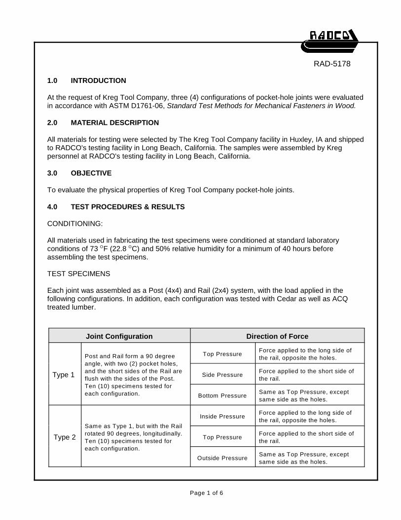
1.0 INTRODUCTION
At the request of Kreg Tool Company, three (4) configurations of pocket-hole joints were evaluatedin accordance with ASTM D1761-06, Standard Test Methods for Mechanical Fasteners in Wood.
2.0 MATERIAL DESCRIPTION
All materials for testing were selected by The Kreg Tool Company facility in Huxley, IA and shippedto RADCO's testing facility in Long Beach, California. The samples were assembled by Kregpersonnel at RADCO's testing facility in Long Beach, California.
3.0 OBJECTIVE
To evaluate the physical properties of Kreg Tool Company pocket-hole joints.
4.0 TEST PROCEDURES & RESULTS
CONDITIONING:
All materials used in fabricating the test specimens were conditioned at standard laboratoryconditions of 73 F (22.8 C) and 50% relative humidity for a minimum of 40 hours beforeO O
assembling the test specimens.
TEST SPECIMENS
Each joint was assembled as a Post (4x4) and Rail (2x4) system, with the load applied in thefollowing configurations. In addition, each configuration was tested with Cedar as well as ACQtreated lumber.
Joint Configuration Direction of Force
Type 1
Post and Rail form a 90 degree
angle, with two (2) pocket holes,
and the short sides of the Rail are
flush with the sides of the Post.
Ten (10) specimens tested for
each configuration.
Top PressureForce applied to the long side of
the rail, opposite the holes.
Side PressureForce applied to the short side of
the rail.
Bottom PressureSame as Top Pressure, except
same side as the holes.
Type 2
Same as Type 1, but with the Rail
rotated 90 degrees, longitudinally.
Ten (10) specimens tested for
each configuration.
Inside PressureForce applied to the long side of
the rail, opposite the holes.
Top PressureForce applied to the short side of
the rail.
Outside PressureSame as Top Pressure, except
same side as the holes.
RAD-5178
Page 2 of 6
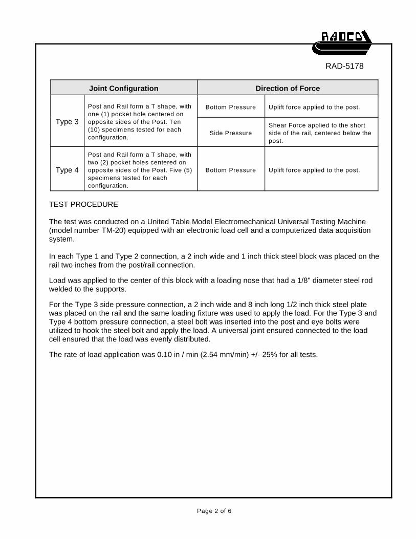
Joint Configuration Direction of Force
Type 3
Post and Rail form a T shape, with
one (1) pocket hole centered on
opposite sides of the Post. Ten
(10) specimens tested for each
configuration.
Bottom Pressure Uplift force applied to the post.
Side Pressure
Shear Force applied to the short
side of the rail, centered below the
post.
Type 4
Post and Rail form a T shape, with
two (2) pocket holes centered on
opposite sides of the Post. Five (5)
specimens tested for each
configuration.
Bottom Pressure Uplift force applied to the post.
TEST PROCEDURE
The test was conducted on a United Table Model Electromechanical Universal Testing Machine(model number TM-20) equipped with an electronic load cell and a computerized data acquisitionsystem.
In each Type 1 and Type 2 connection, a 2 inch wide and 1 inch thick steel block was placed on therail two inches from the post/rail connection.
Load was applied to the center of this block with a loading nose that had a 1/8" diameter steel rodwelded to the supports.
For the Type 3 side pressure connection, a 2 inch wide and 8 inch long 1/2 inch thick steel platewas placed on the rail and the same loading fixture was used to apply the load. For the Type 3 andType 4 bottom pressure connection, a steel bolt was inserted into the post and eye bolts wereutilized to hook the steel bolt and apply the load. A universal joint ensured connected to the loadcell ensured that the load was evenly distributed.
The rate of load application was 0.10 in / min (2.54 mm/min) +/- 25% for all tests.
RAD-5178
Page 3 of 6
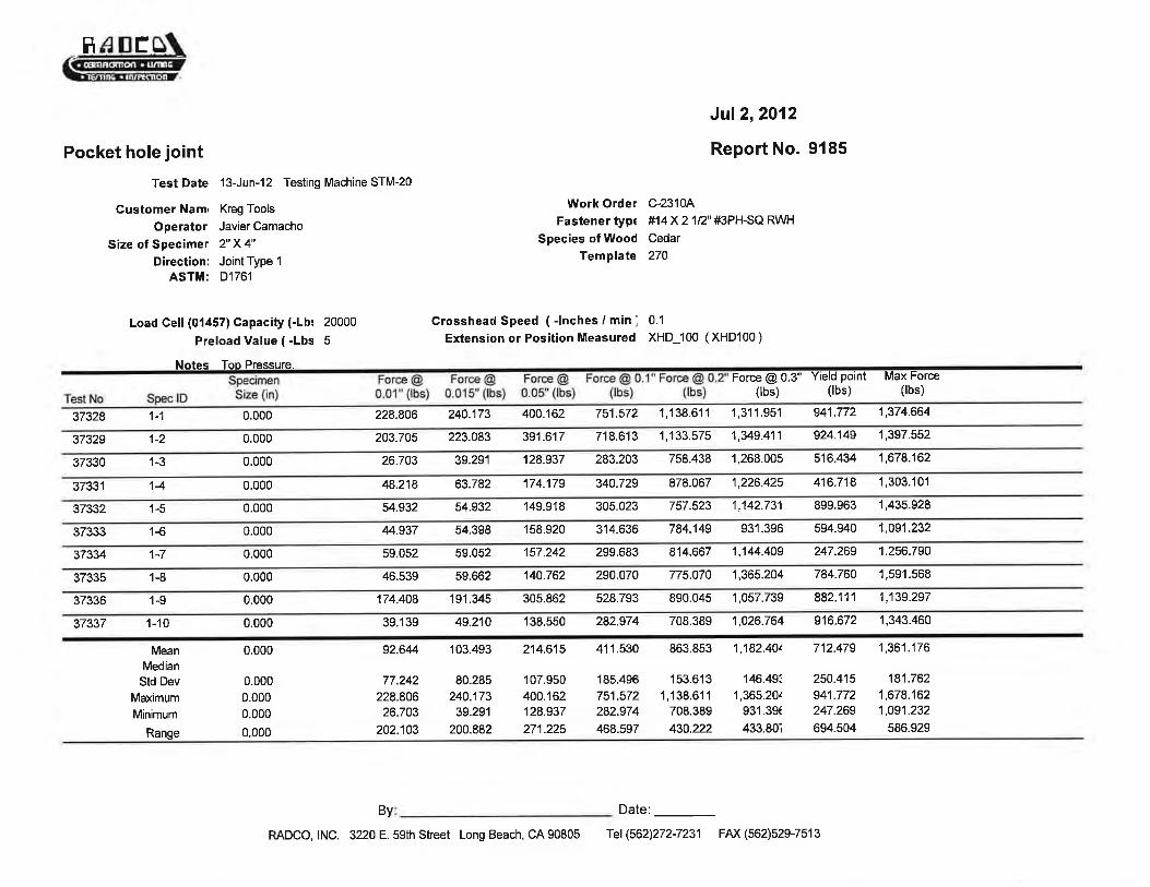
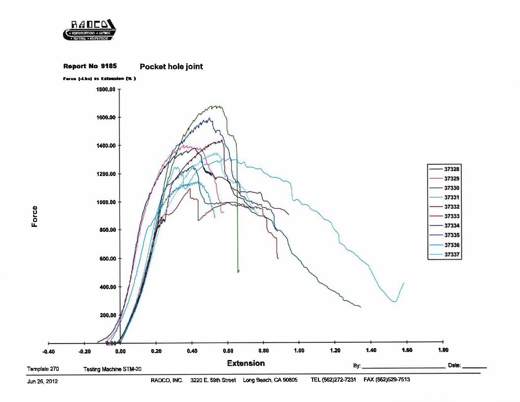
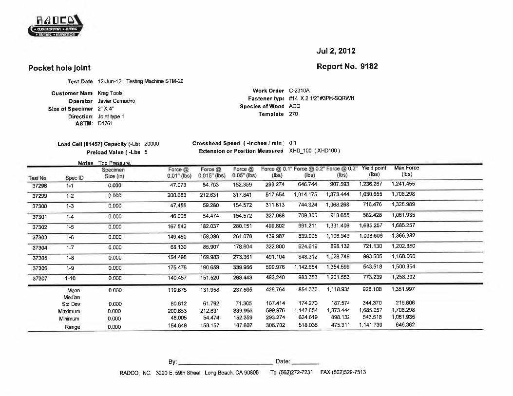
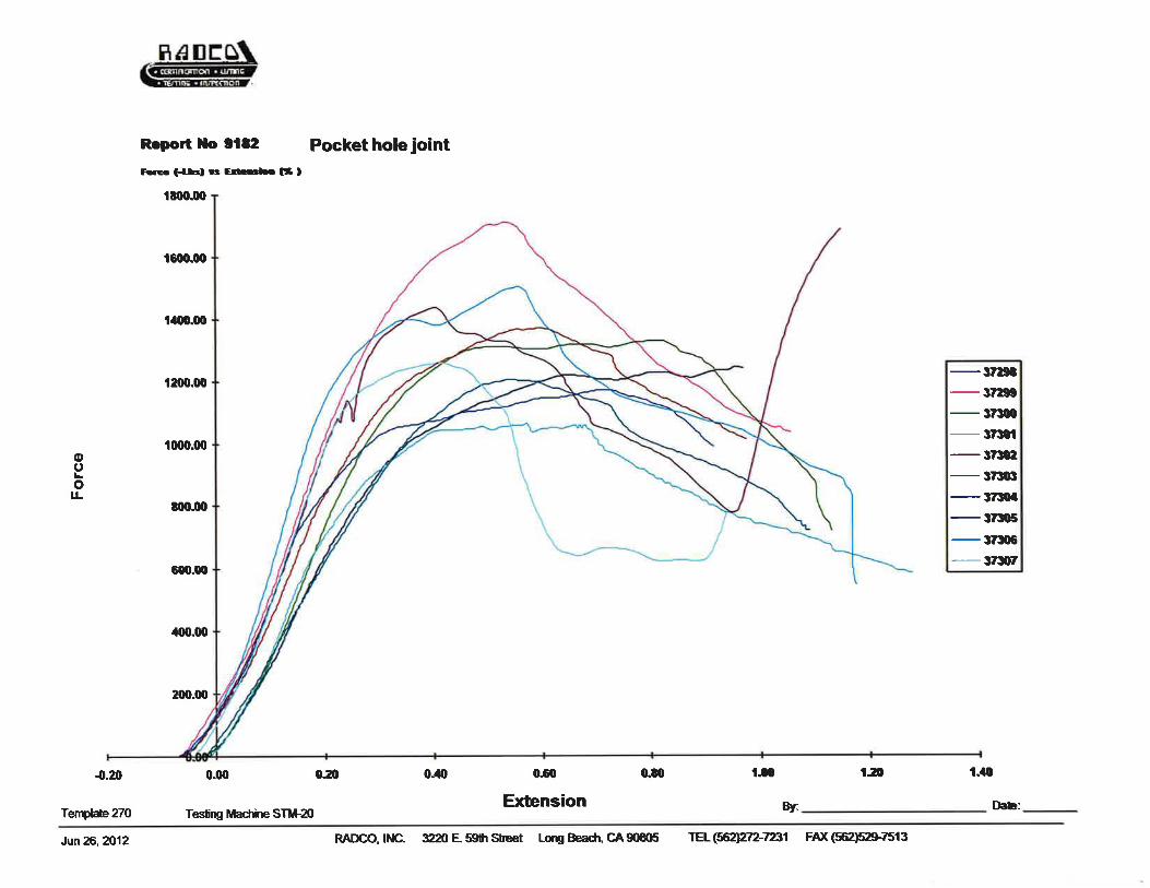
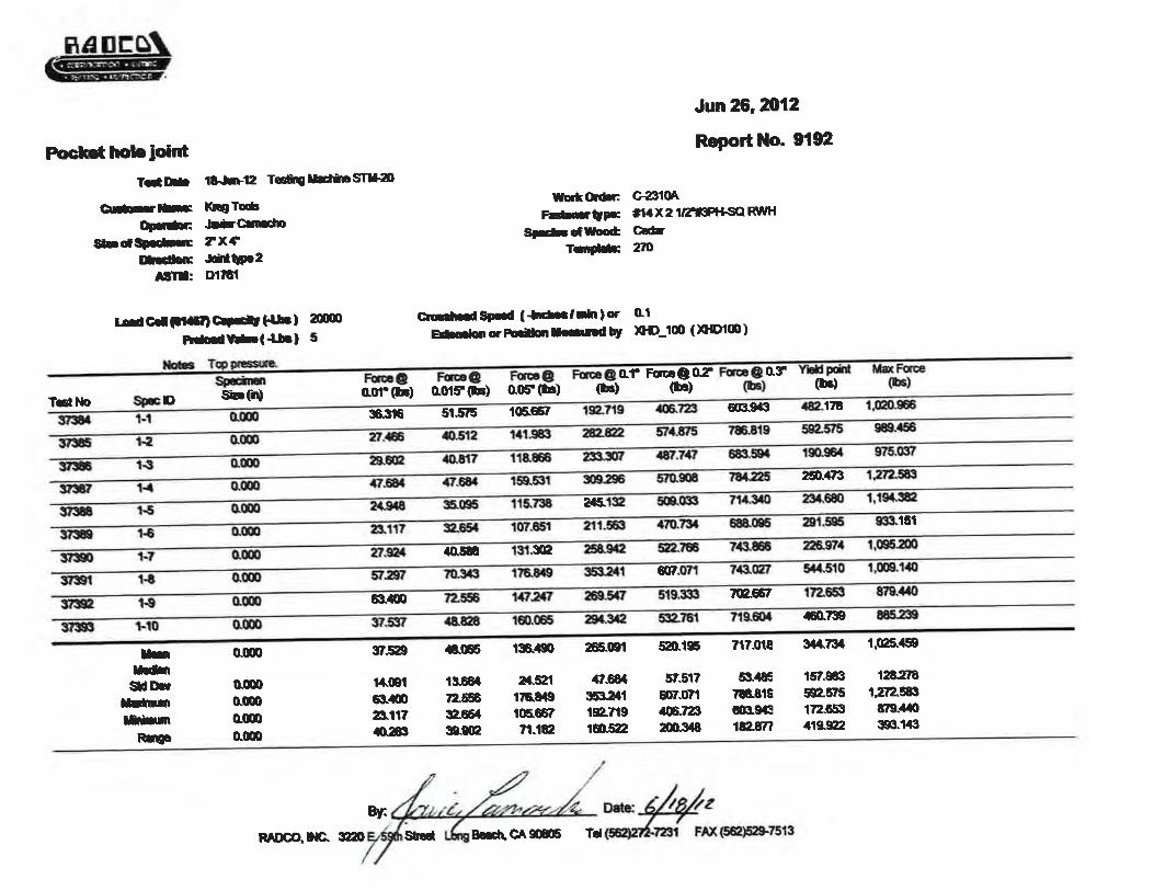
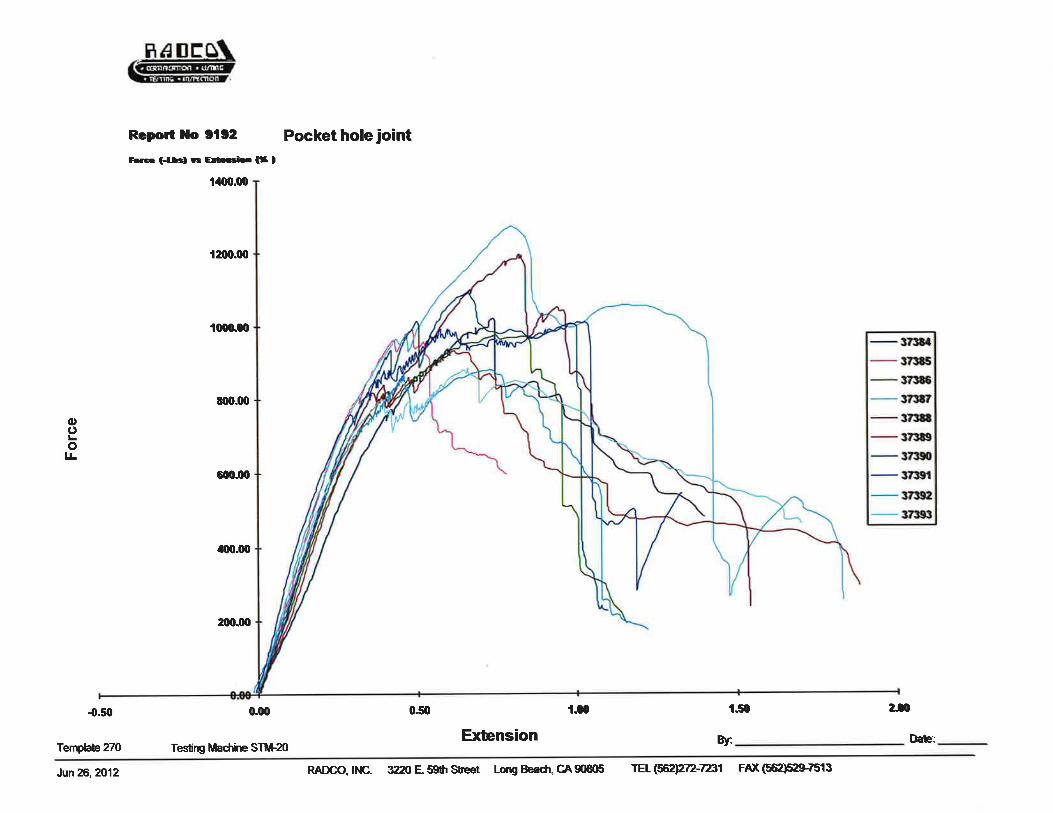
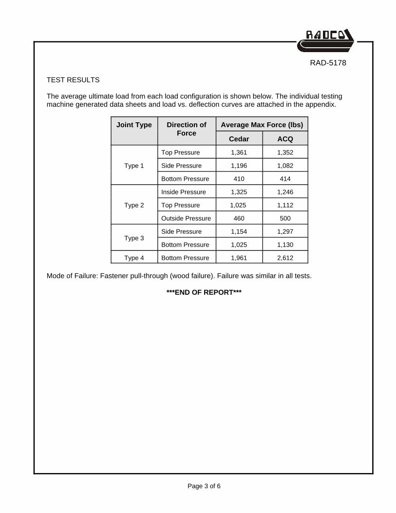
TEST RESULTS
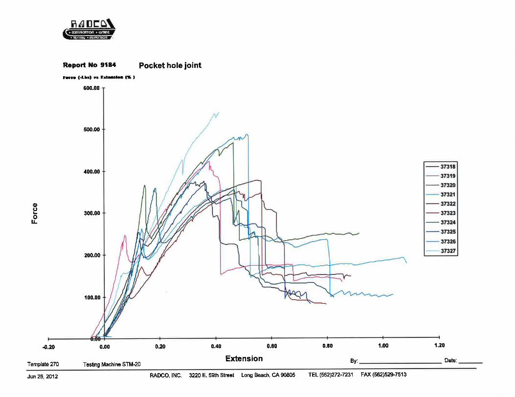
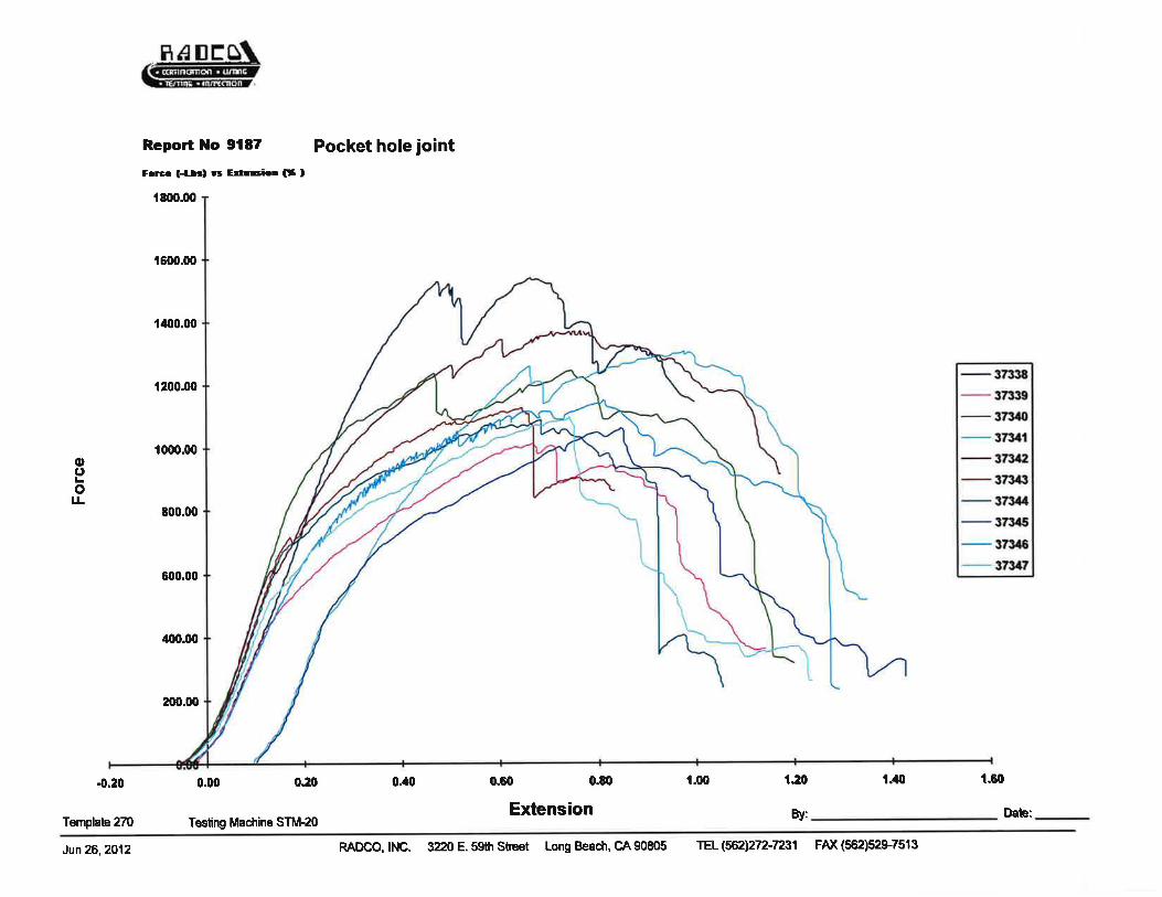
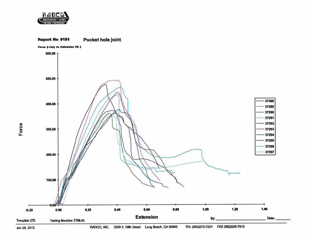
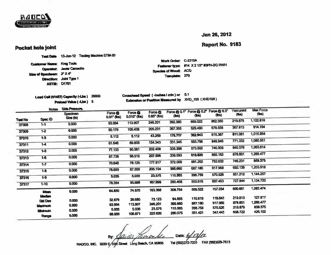
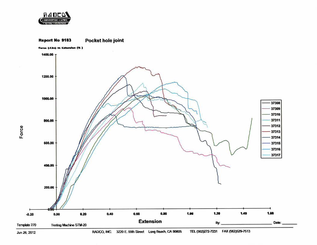
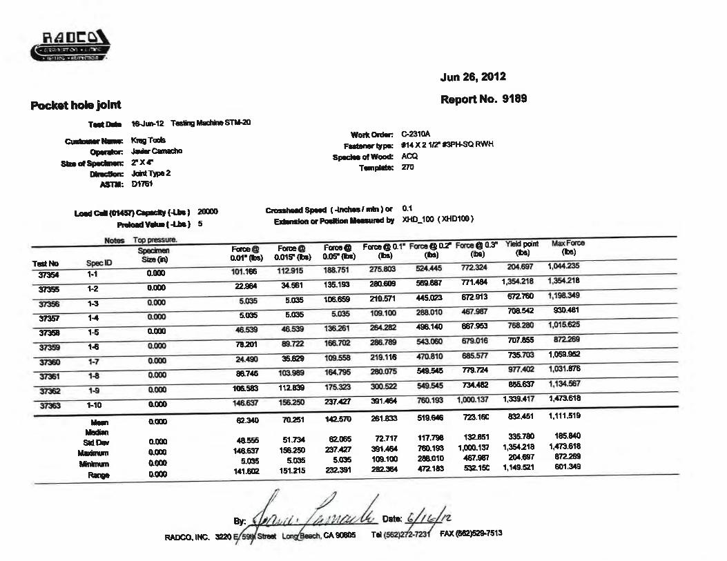
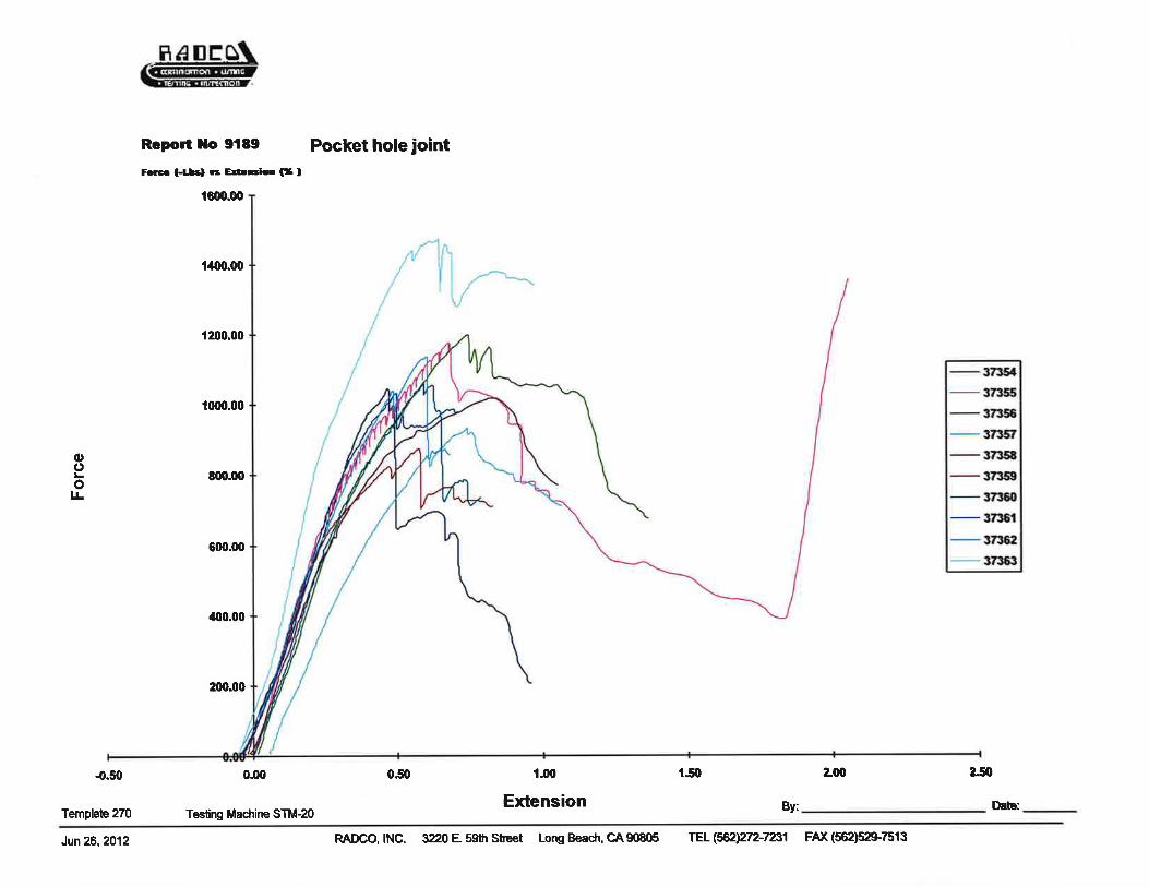
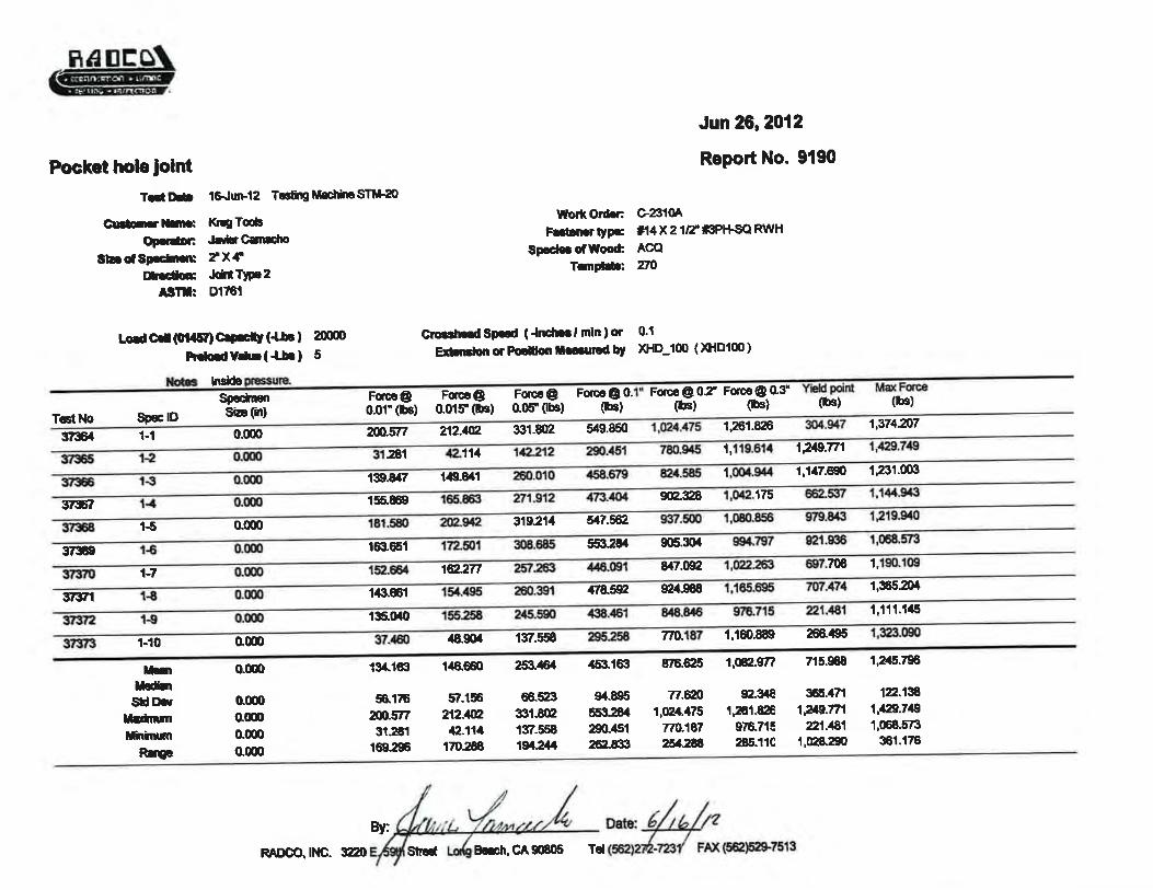
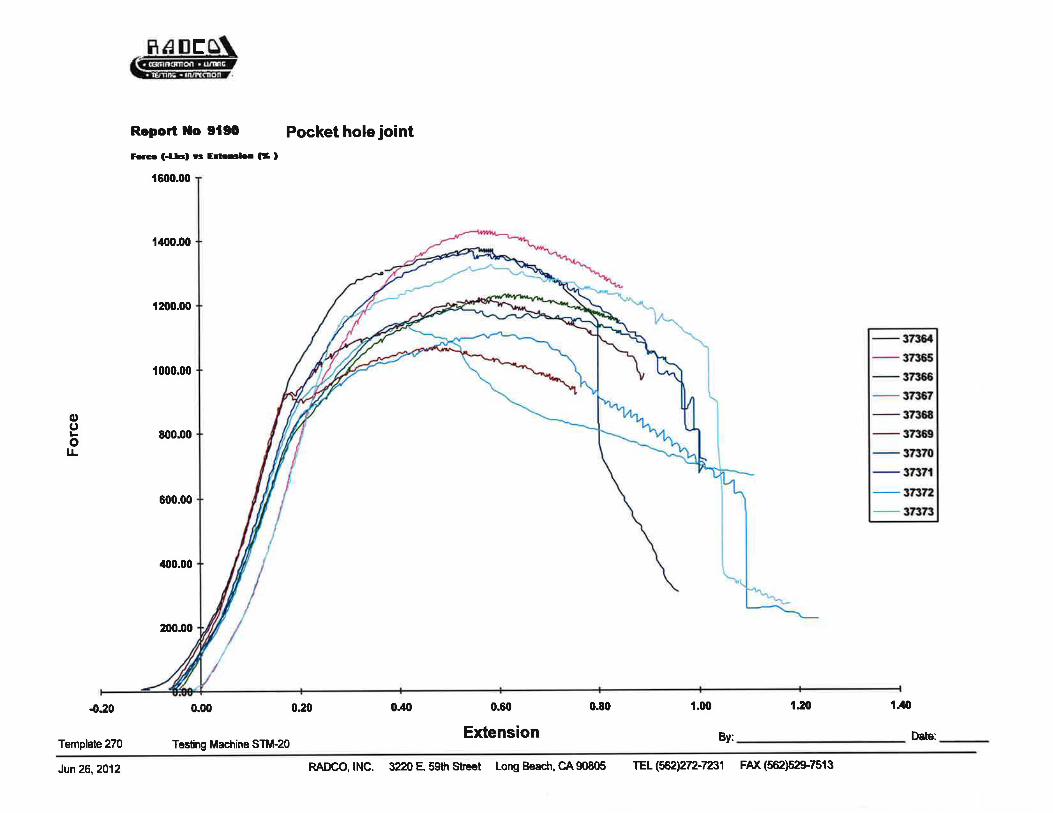
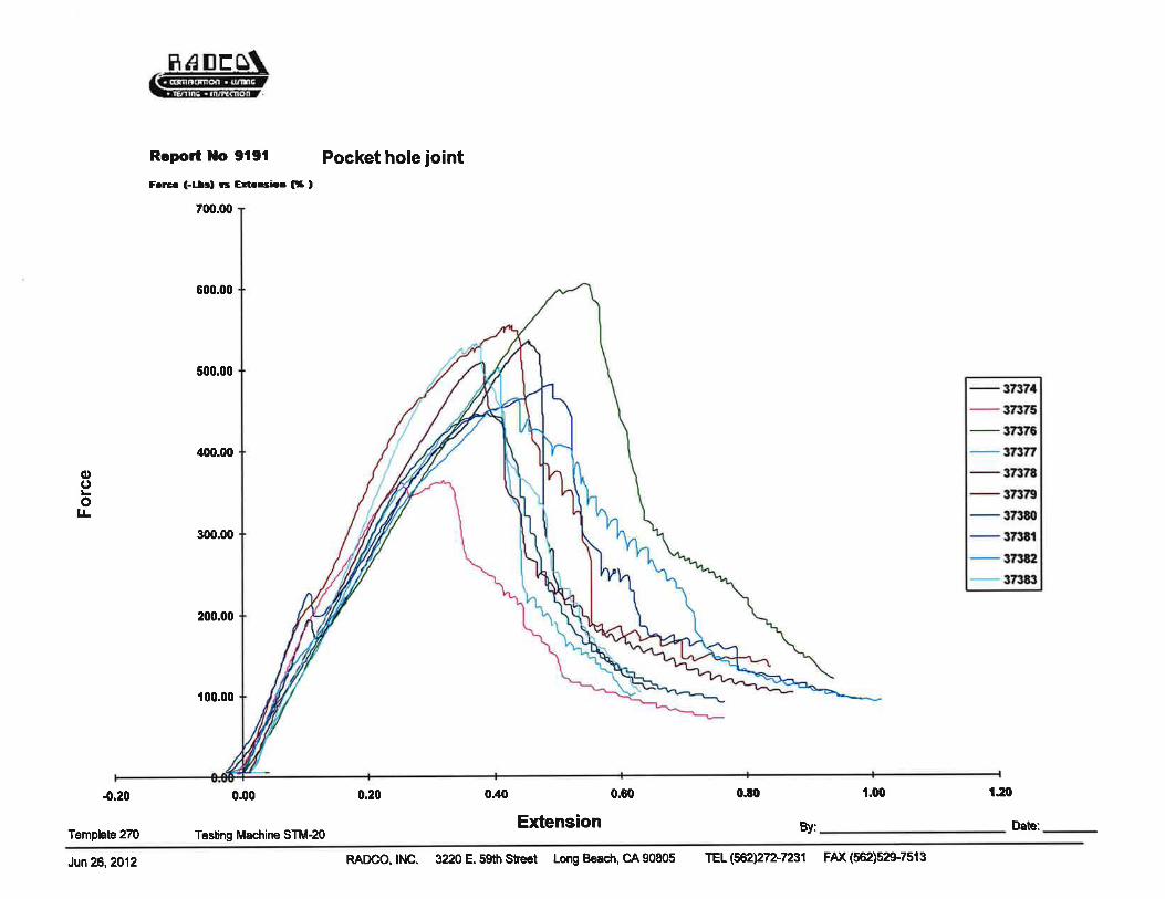
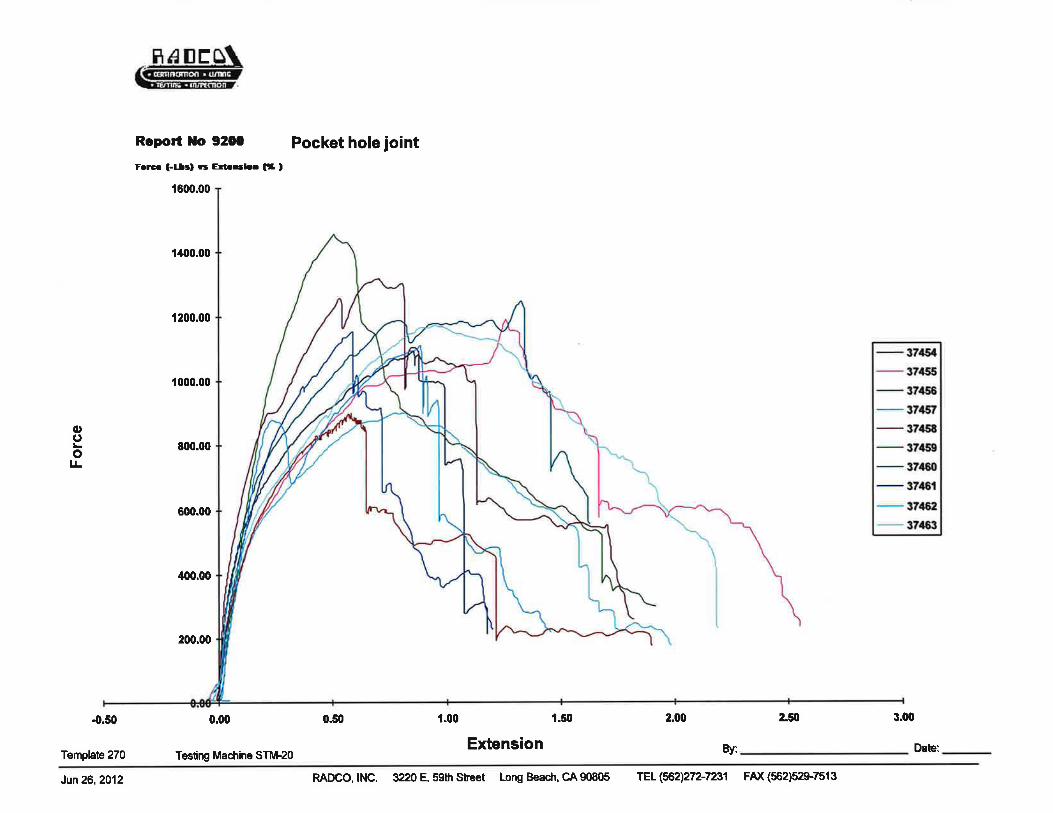
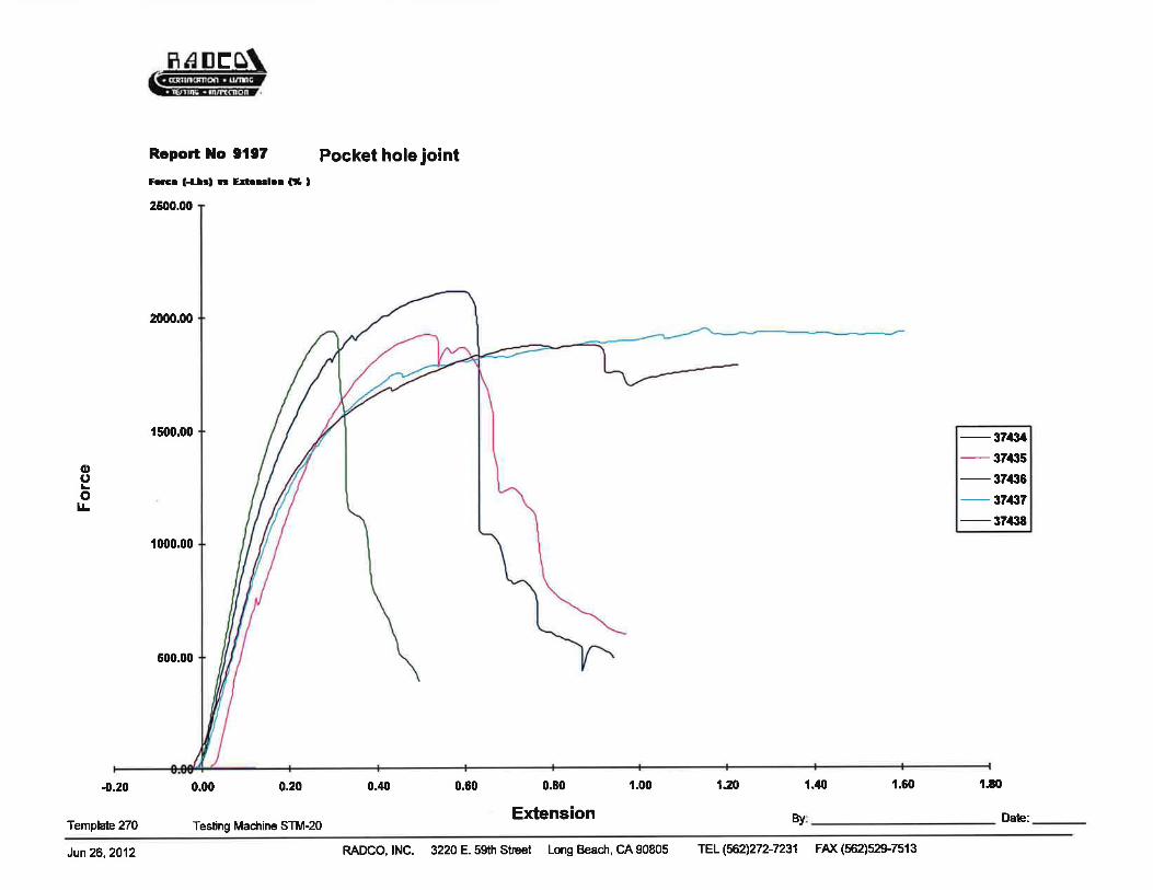
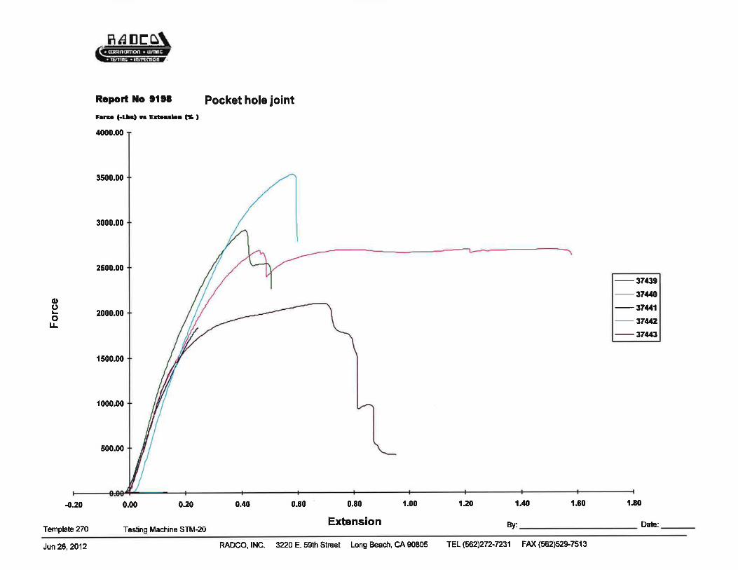
The average ultimate load from each load configuration is shown below. The individual testingmachine generated data sheets and load vs. deflection curves are attached in the appendix.
Joint Type Direction ofForce
Average Max Force (lbs)
Cedar ACQ
Type 1
Top Pressure 1,361 1,352
Side Pressure 1,196 1,082
Bottom Pressure 410 414
Type 2
Inside Pressure 1,325 1,246
Top Pressure 1,025 1,112
Outside Pressure 460 500
Type 3Side Pressure 1,154 1,297
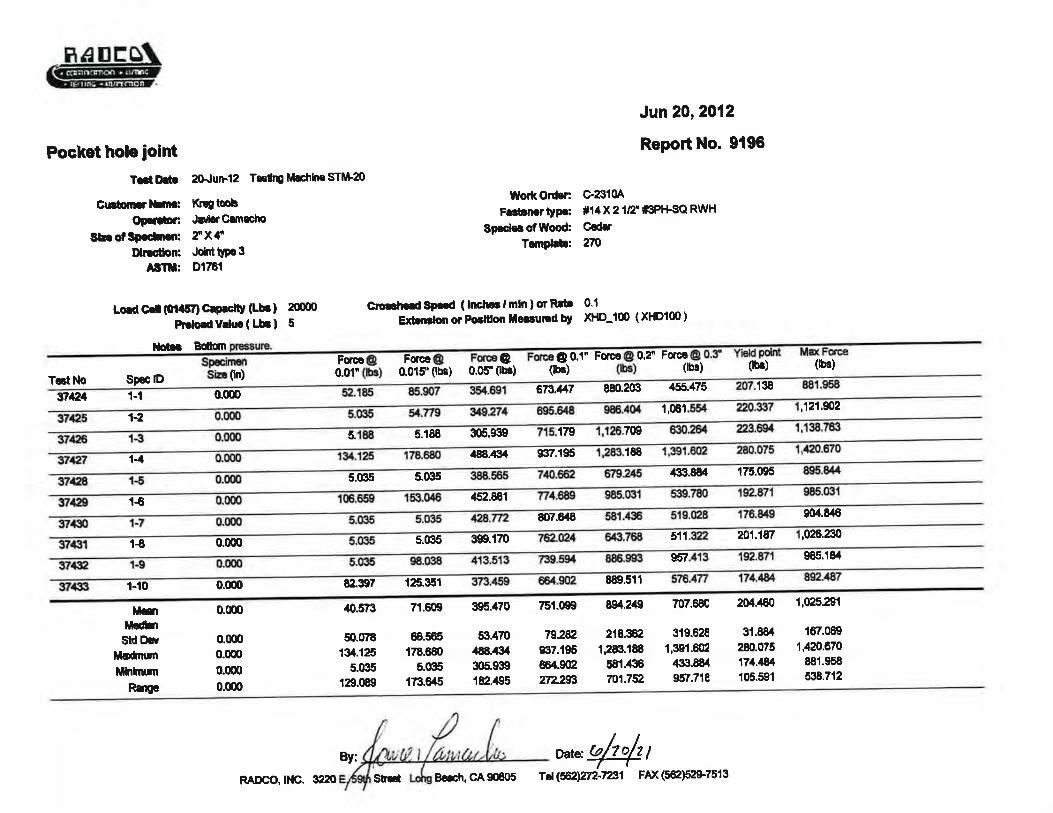
Bottom Pressure 1,025 1,130
Type 4 Bottom Pressure 1,961 2,612
Mode of Failure: Fastener pull-through (wood failure). Failure was similar in all tests.
***END OF REPORT***
RAD-5178
Page 4 of 6
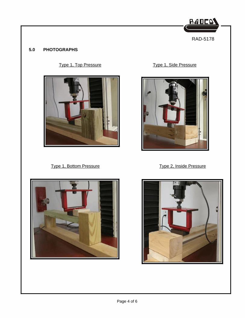
5.0 PHOTOGRAPHS
Type 1, Top Pressure Type 1, Side Pressure
Type 1, Bottom Pressure Type 2, Inside Pressure
RAD-5178
Page 5 of 6
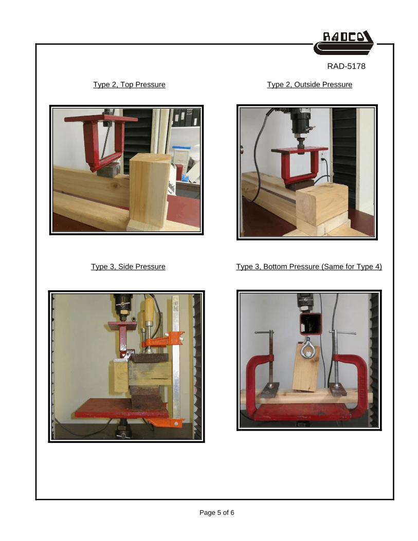
Type 2, Top Pressure Type 2, Outside Pressure
Type 3, Side Pressure Type 3, Bottom Pressure (Same for Type 4)
RAD-5178
Page 6 of 6
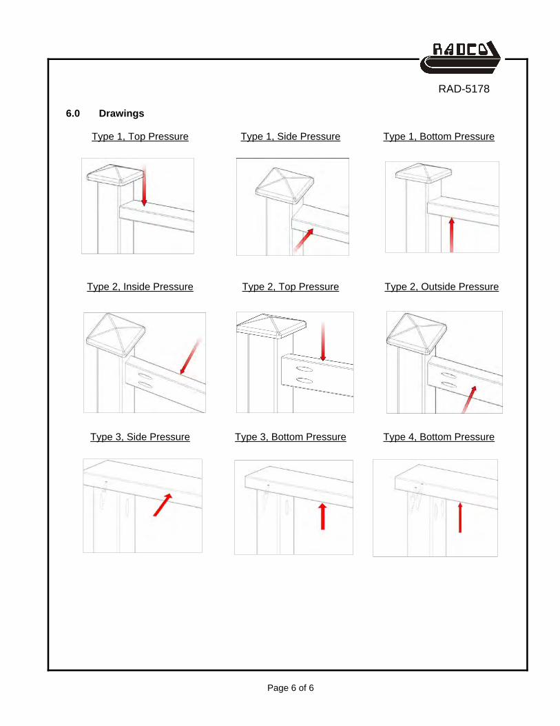
6.0 Drawings
Type 1, Top Pressure
Type 2, Inside Pressure
Type 3, Side Pressure
Type 1, Side Pressure
Type 2, Top Pressure
Type 3, Bottom Pressure
Type 1, Bottom Pressure
Type 2, Outside Pressure
Type 4, Bottom Pressure
RAD-5178
APPENDIXTest data index (1 page)
Testing machine generated data (36 pages total)
RAD-5178
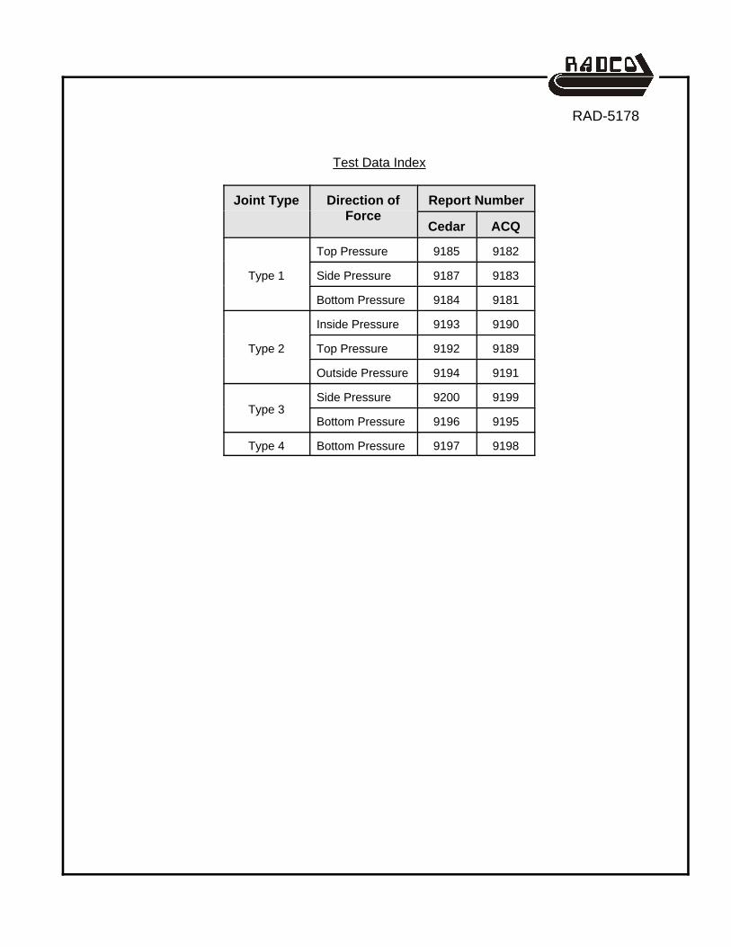
Test Data Index
Joint Type Direction ofForce
Report Number
Cedar ACQ
Type 1
Top Pressure 9185 9182
Side Pressure 9187 9183
Bottom Pressure 9184 9181
Type 2
Inside Pressure 9193 9190
Top Pressure 9192 9189
Outside Pressure 9194 9191
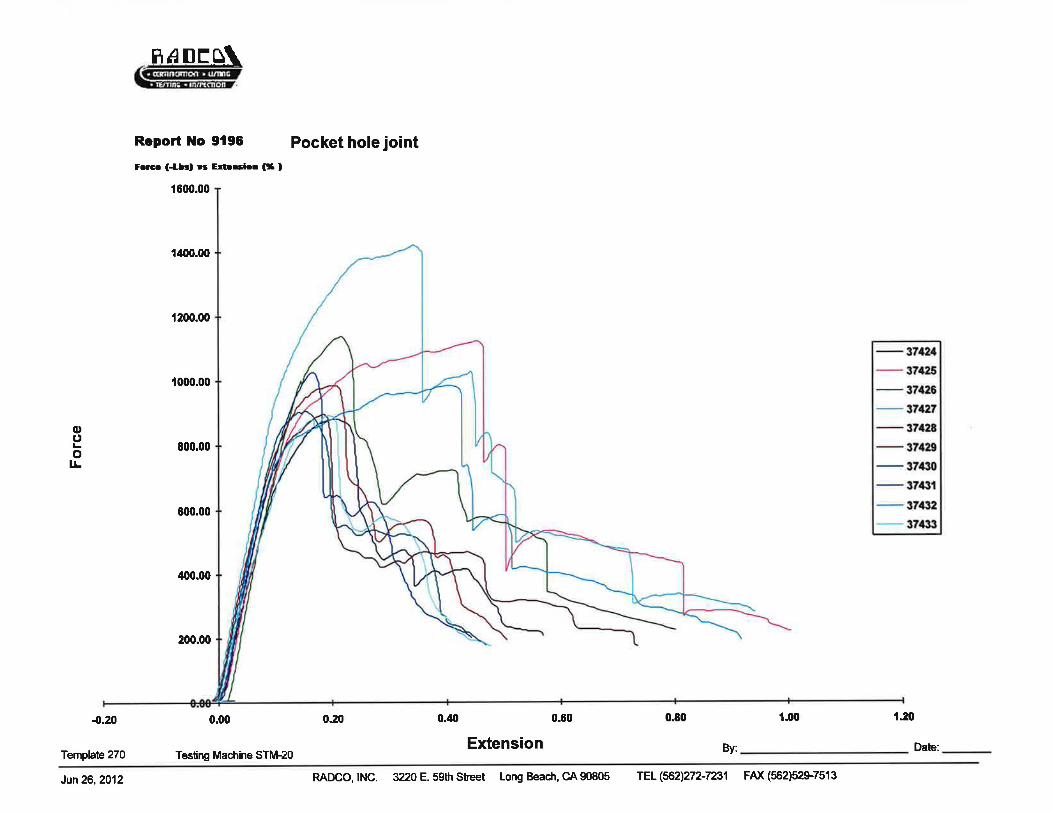
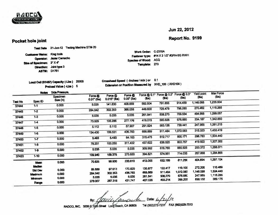
Type 3Side Pressure 9200 9199
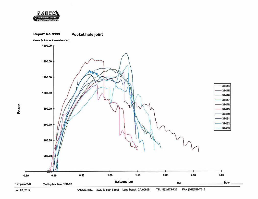
Bottom Pressure 9196 9195
Type 4 Bottom Pressure 9197 9198