Embed Size (px)
Citation preview
Operating Instructions
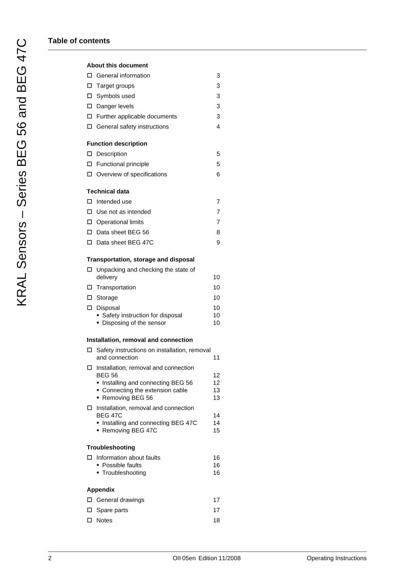
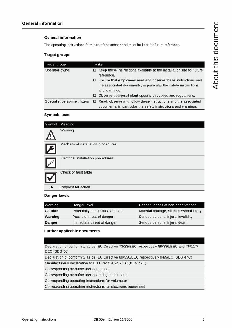
KRAL Sensors.Series BEG 56 and BEG 47C.
OII 05enEdition 11/2008
2 OII 05en Edition 11/2008 Operating Instructions
Table of contents
KR
AL
Sen
sors
– S
erie
s B
EG
56
and
BE
G 4
7C
About this document
General information 3
Target groups 3
Symbols used 3
Danger levels 3
Further applicable documents 3
General safety instructions 4
Function description
Description 5
Functional principle 5
Overview of specifications 6
Technical data
Intended use 7
Use not as intended 7
Operational limits 7
Data sheet BEG 56 8
Data sheet BEG 47C 9
Transportation, storage and disposal
Unpacking and checking the state of delivery 10
Transportation 10
Storage 10
Disposal 10Safety instruction for disposal 10Disposing of the sensor 10
Installation, removal and connection
Safety instructions on installation, removal and connection 11
Installation, removal and connection BEG 56 12
Installing and connecting BEG 56 12Connecting the extension cable 13Removing BEG 56 13
Installation, removal and connection BEG 47C 14
Installing and connecting BEG 47C 14Removing BEG 47C 15
Troubleshooting
Information about faults 16Possible faults 16Troubleshooting 16
Appendix
General drawings 17
Spare parts 17
Notes 18
Operating Instructions OII 05en Edition 11/2008 3
General information
Abo
ut th
is d
ocum
ent
About this document General information
The operating instructions form part of the sensor and must be kept for future reference.
Target groups
Symbols used
Danger levels
Further applicable documents
Target group Tasks
Operator-owner Keep these instructions available at the installation site for future reference.
Ensure that employees read and observe these instructions and the associated documents, in particular the safety instructions and warnings.
Observe additional plant-specific directives and regulations.
Specialist personnel, fitters Read, observe and follow these instructions and the associated documents, in particular the safety instructions and warnings.
Symbol Meaning
Warning
Mechanical installation procedures
Electrical installation procedures
Check or fault table
➤ Request for action
Warning Danger level Consequences of non-observances
Caution Potentially dangerous situation Material damage, slight personal injury
Warning Possible threat of danger Serious personal injury, invalidity
Danger Immediate threat of danger Serious personal injury, death
Declaration of conformity as per EU Directive 73/23/EEC respectively 89/336/EEC and 76/117/EEC (BEG 56)
Declaration of conformity as per EU Directive 89/336/EEC respectively 94/9/EC (BEG 47C)
Manufacturer's declaration to EU Directive 94/9/EC (BEG 47C)
Corresponding manufacturer data sheet
Corresponding manufacturer operating instructions
Corresponding operating instructions for volumeter
Corresponding operating instructions for electronic equipment

4 OII 05en Edition 11/2008 Operating Instructions
General safety instructions
Abo
ut th
is d
ocum
ent
General safety instructions
The following general safety instructions must be observed:
No liability is accepted for damage arising through non-observance of the operating
instructions.Read the operating instructions carefully and observe them.
The operator-owner is responsible for the observance of the operating instructions.
Installation, removal and installation work may only be carried out by specialist personnel.
Do not use KRAL sensors outside the operational limits specified in the "Technical data" section. In the case of operating data that do not agree with the specifications in the "Technical
data" section, contact the manufacturer. In order for the warranty to remain valid, corrective maintenance during the warranty period require the express permission of the manufacturer.
Observe the general regulations for the prevention of accidents as well as the local safety and operating instructions.Observe the valid national and international standards and specifications of the installation
location.Implement all the supply lines without faults.The sensor system (sensor, transducer and lines) may not be located in the area of strong,
high-frequency electromagnetic fields, such as those emitted e.g. from power lines, electric motors, frequency converters, etc. This can lead to erroneous measurements or the destruction of the sensor system.
In case of plants with an increased potential of danger to humans and/or machines the failure of a sensor may not lead to injuries or damage to property.
Always equip systems with an increased potential of danger with alarm equipment.Maintain and check the protective/alarm equipment regularly.
The pumped liquids may be dangerous (for example hot, dangerous to health, poisonous,
combustible). Observe the safety regulations for handling dangerous materials.Pumped liquids can be subject to high pressure and can cause damage and/or personal injury
should leaks occur.Depending on operating conditions, the service life of the sensors is limited due to vibrations, temperature influences or deterioration. The operator-owner is responsible for regular
inspection.All parts which jeopardize safe operation must be replaced regularly.
Abnormal operating mode or visible damage prohibits further use.
Operating Instructions OII 05en Edition 11/2008 5
Description
Fun
ctio
n de
scrip
tion
Function description Description
Functional principle
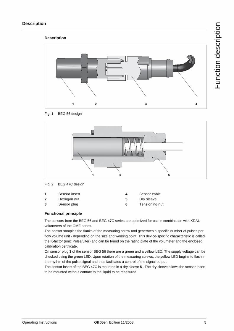
The sensors from the BEG 56 and BEG 47C series are optimized for use in combination with KRAL volumeters of the OME series. The sensor samples the flanks of the measuring screw and generates a specific number of pulses per
flow volume unit - depending on the size and working point. This device-specific characteristic is called the K-factor (unit: Pulse/Liter) and can be found on the rating plate of the volumeter and the enclosed calibration certificate.
On sensor plug 3 of the sensor BEG 56 there are a green and a yellow LED. The supply voltage can be checked using the green LED. Upon rotation of the measuring screws, the yellow LED begins to flash in the rhythm of the pulse signal and thus facilitates a control of the signal output.
The sensor insert of the BEG 47C is mounted in a dry sleeve 5 . The dry sleeve allows the sensor insert to be mounted without contact to the liquid to be measured.
Fig. 1 BEG 56 design
Fig. 2 BEG 47C design
123
Sensor insertHexagon nut
Sensor plug
456
Sensor cableDry sleeve
Tensioning nut
1 2 3 4
1 5 6
6 OII 05en Edition 11/2008 Operating Instructions
Overview of specifications
Fun
ctio
n de
scrip
tion
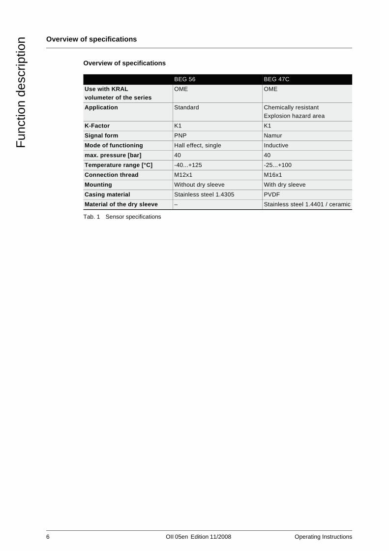
Overview of specifications
Tab. 1 Sensor specifications
BEG 56 BEG 47C
Use with KRAL volumeter of the series
OME OME
Application Standard Chemically resistantExplosion hazard area
K-Factor K1 K1
Signal form PNP Namur
Mode of functioning Hall effect, single Inductive
max. pressure [bar] 40 40
Temperature range [°C] -40...+125 -25...+100
Connection thread M12x1 M16x1
Mounting Without dry sleeve With dry sleeve
Casing material Stainless steel 1.4305 PVDF
Material of the dry sleeve – Stainless steel 1.4401 / ceramic
Operating Instructions OII 05en Edition 11/2008 7
Intended use
Tec
hnic
al d
ata
Technical data Intended use
KRAL Sensors of the BEG 56 and BEG 47C series are intended exclusively for use with KRAL
volumeters of the OME series. The sensors may only be used within the operational limits described within this chapter.
Use not as intended
The sensors are not suitable for all other use except for use with KRAL volumeters. The sensors may not be used outside the operational limits described within this chapter. Operating data which deviate from the values can lead to damage. If there is any doubt whether deviating operating data can cause
damage, inform the manufacturer.
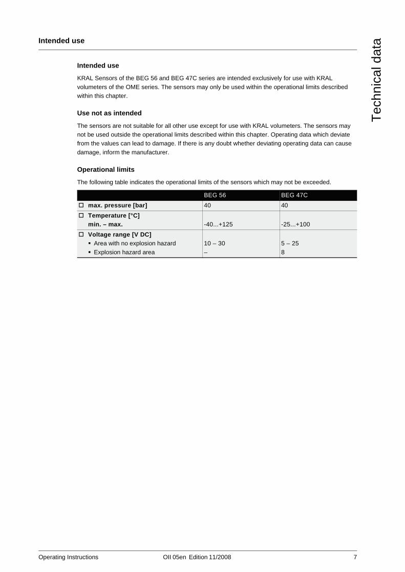
Operational limits
The following table indicates the operational limits of the sensors which may not be exceeded.
BEG 56 BEG 47C
max. pressure [bar] 40 40
Temperature [°C]min. – max. -40...+125 -25...+100
Voltage range [V DC]Area with no explosion hazard
Explosion hazard area
10 – 30
–
5 – 25
8
8 OII 05en Edition 11/2008 Operating Instructions
Data sheet BEG 56
Tec
hnic
al d
ata
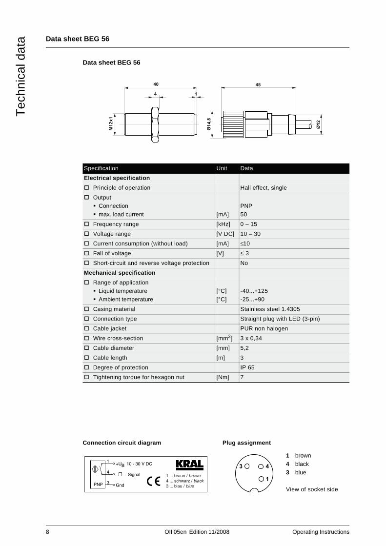
Data sheet BEG 56
Specification Unit Data
Electrical specification
Principle of operation Hall effect, single
OutputConnection
max. load current [mA]
PNP
50
Frequency range [kHz] 0 – 15
Voltage range [V DC] 10 – 30
Current consumption (without load) [mA] ≤ 10
Fall of voltage [V] ≤ 3
Short-circuit and reverse voltage protection No
Mechanical specification
Range of applicationLiquid temperatureAmbient temperature
[°C][°C]
-40...+125-25...+90
Casing material Stainless steel 1.4305
Connection type Straight plug with LED (3-pin)
Cable jacket PUR non halogen
Wire cross-section [mm2] 3 x 0,34
Cable diameter [mm] 5,2
Cable length [m] 3
Degree of protection IP 65
Tightening torque for hexagon nut [Nm] 7
Connection circuit diagram Plug assignment
1 brown
4 black3 blue
View of socket side
M12x1
40
4 1
Ø12
Ø14,8
45
PNP
Signal
Gnd
B+U 10 - 30 V DC1
4
3
1 ... braun / brown4 ... schwarz / black3 ... blau / blue
3 4
1
Operating Instructions OII 05en Edition 11/2008 9
Data sheet BEG 47C
Tec
hnic
al d
ata
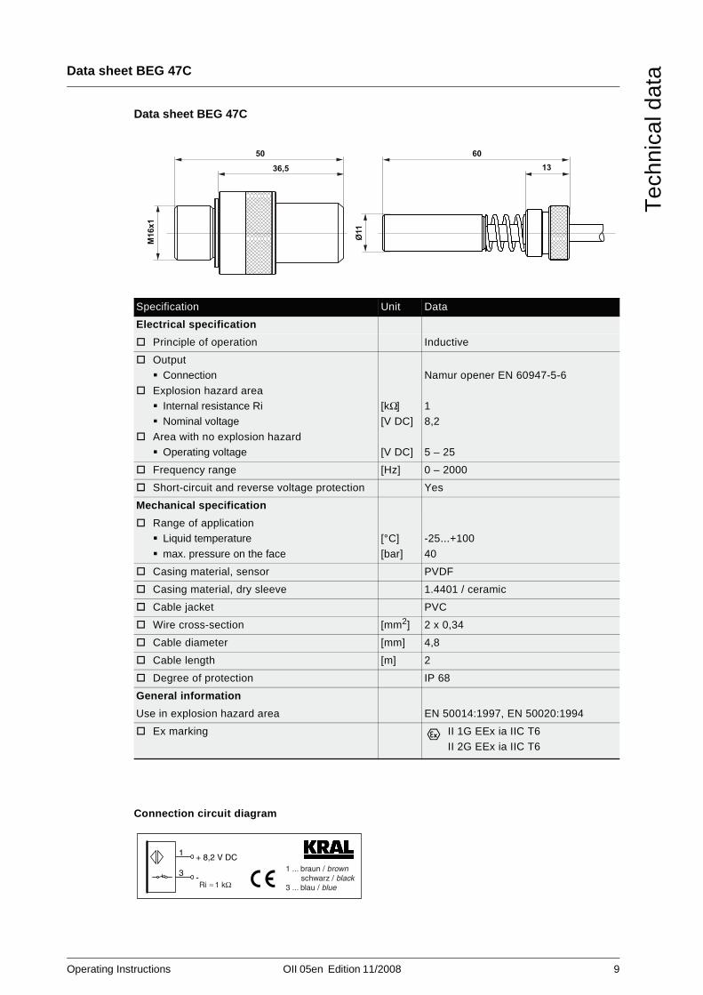
Data sheet BEG 47C
Specification Unit Data
Electrical specification
Principle of operation Inductive
OutputConnection
Explosion hazard areaInternal resistance RiNominal voltage
Area with no explosion hazardOperating voltage
[kΩ][V DC]
[V DC]
Namur opener EN 60947-5-6
18,2
5 – 25
Frequency range [Hz] 0 – 2000
Short-circuit and reverse voltage protection Yes
Mechanical specification
Range of applicationLiquid temperature
max. pressure on the face
[°C]
[bar]
-25...+100
40
Casing material, sensor PVDF
Casing material, dry sleeve 1.4401 / ceramic
Cable jacket PVC
Wire cross-section [mm2] 2 x 0,34
Cable diameter [mm] 4,8
Cable length [m] 2
Degree of protection IP 68
General information
Use in explosion hazard area EN 50014:1997, EN 50020:1994
Ex marking II 1G EEx ia IIC T6II 2G EEx ia IIC T6
Connection circuit diagram
M16x1
50
36,5
Ø11
6013
1 ... braun / brown schwarz / black3 ... blau / blueRi 1 kΩ
1
-3
+ 8,2 V DC
10 OII 05en Edition 11/2008 Operating Instructions
Unpacking and checking the state of delivery
Tra
nspo
rtat
ion,
sto
rage
and
dis
posa
l
Transportation, storage and disposal Unpacking and checking the state of delivery
1. On delivery unpack the sensor and check for damage during transportation.
2. Report damage during transportation immediately to the manufacturer.3. Dispose of packing material in accordance with the locally applicable regulations.
Transportation
1. If possible, transport sensor in original packaging.2. Do not kink sensor cable.
Storage
➤ If possible, store the sensor in original packaging in a cool and dry place.
Disposal
Safety instruction for disposal
Disposing of the sensor
➤ Dispose of the sensor as electronic waste.
Note the following on disposal:
Observe the local regulations on disposal.
Operating Instructions OII 05en Edition 11/2008 11
Safety instructions on installation, removal and connection
Inst
alla
tion,
rem
oval
and
con
nect
ion
Installation, removal and connection Safety instructions on installation, removal and connection
The following safety instructions must be observed:
All installation and removal work may only be carried out by qualified personnel.
The following qualifications are required for the electrical connection:Practical electrotechnical trainingKnowledge of the safety guidelines at the workplace
Knowledge of the electrotechnical safety guidelines
The sensor system (sensor, transducer and lines) may not be located in the area of strong, high-frequency electromagnetic fields. This could lead to erroneous measurements or even to the destruction of the sensor system.
➤ The connecting lines of the sensor connections are to be shielded and laid separately from the
supply and measuring lines.➤ Ensure that the supply voltage is correct.

12 OII 05en Edition 11/2008 Operating Instructions
Installation, removal and connection BEG 56
Inst
alla
tion,
rem
oval
and
con
nect
ion
Installation, removal and connection BEG 56
Installing and connecting BEG 56
Fig. 1 General drawing BEG 56
493624.1
Sensor plugSensor insert
624.2 Hexagon nut
Fig. 2 Mounting BEG 56 Fig. 3 Terminal diagram BEG 56
624.1
624.2
493
624.1
493
PNP
Signal
Gnd
B+U 10 - 30 V DC1
4
3
1 ... braun / brown4 ... schwarz / black3 ... blau / blue
DANGERRisk of death resulting from electric shock
➤ The sensor may only be connected by an authorized electrician.➤ Connect the sensor to the correct supply voltage, see terminal diagram BEG 56, Fig. 3.
CAUTIONFaulty wiring destroys the sensor.
➤ Wire the sensor according to terminal diagram and plug assignment, see "Data sheet BEG 56",
page 8.
Operating Instructions OII 05en Edition 11/2008 13
Installation, removal and connection BEG 56
Inst
alla
tion,
rem
oval
and
con
nect
ion
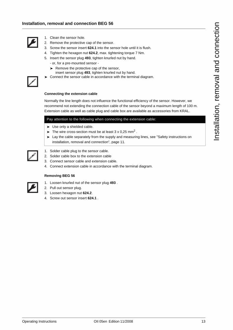
1. Clean the sensor hole.2. Remove the protective cap of the sensor.
3. Screw the sensor insert 624.1 into the sensor hole until it is flush.4. Tighten the hexagon nut 624.2, max. tightening torque 7 Nm.5. Insert the sensor plug 493, tighten knurled nut by hand.
- or, for a pre-mounted sensor -➤ Remove the protective cap of the sensor,
insert sensor plug 493, tighten knurled nut by hand.➤ Connect the sensor cable in accordance with the terminal diagram.
Connecting the extension cable
Normally the line length does not influence the functional efficiency of the sensor. However, we recommend not extending the connection cable of the sensor beyond a maximum length of 100 m. Extension cable as well as cable plug and cable box are available as accessories from KRAL.
1. Solder cable plug to the sensor cable.
2. Solder cable box to the extension cable3. Connect sensor cable and extension cable.4. Connect extension cable in accordance with the terminal diagram.
Removing BEG 56
1. Loosen knurled nut of the sensor plug 493 .
2. Pull out sensor plug.3. Loosen hexagon nut 624.2.
4. Screw out sensor insert 624.1 .
Pay attention to the following when connecting the extension cable:
➤ Use only a shielded cable.➤ The wire cross-section must be at least 3 x 0,25 mm2 .➤ Lay the cable separately from the supply and measuring lines, see "Safety instructions on
installation, removal and connection", page 11.
14 OII 05en Edition 11/2008 Operating Instructions
Installation, removal and connection BEG 47C
Inst
alla
tion,
rem
oval
and
con
nect
ion
Installation, removal and connection BEG 47C
Installing and connecting BEG 47C
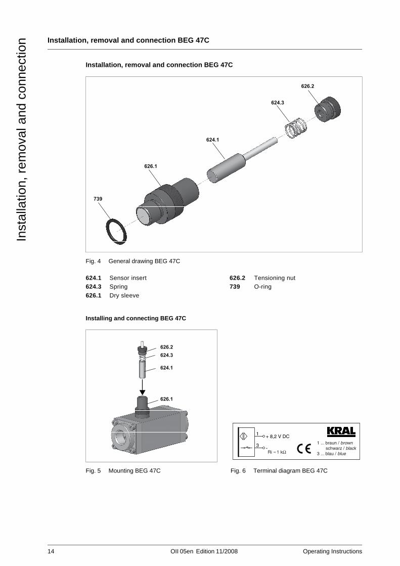
Fig. 4 General drawing BEG 47C
624.1624.3626.1
Sensor insertSpring
Dry sleeve
626.2739
Tensioning nutO-ring
Fig. 5 Mounting BEG 47C Fig. 6 Terminal diagram BEG 47C
739
626.1
624.1
624.3
626.2
626.1
624.1
624.3626.2
1 ... braun / brown schwarz / black3 ... blau / blueRi 1 kΩ
1
-3
+ 8,2 V DC
Operating Instructions OII 05en Edition 11/2008 15
Installation, removal and connection BEG 47C
Inst
alla
tion,
rem
oval
and
con
nect
ion
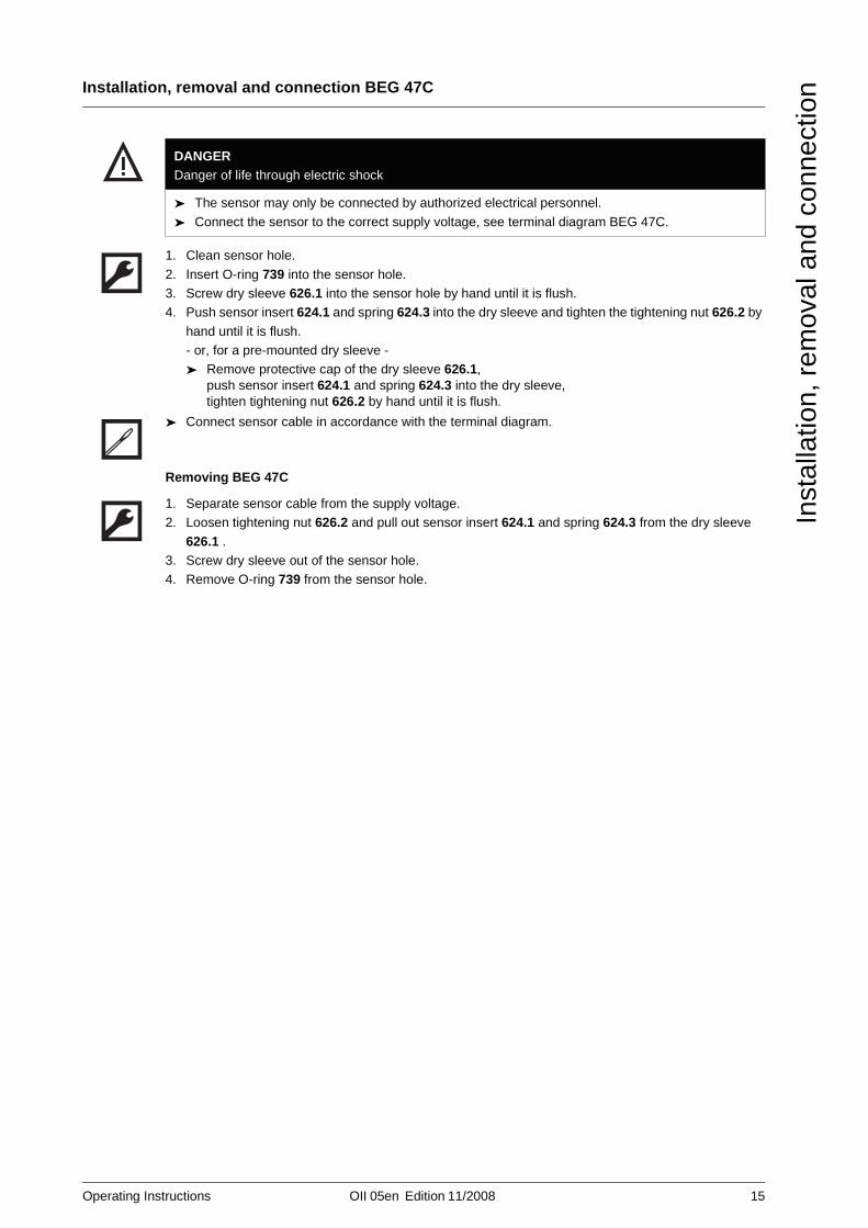
1. Clean sensor hole.
2. Insert O-ring 739 into the sensor hole.3. Screw dry sleeve 626.1 into the sensor hole by hand until it is flush.4. Push sensor insert 624.1 and spring 624.3 into the dry sleeve and tighten the tightening nut 626.2 by
hand until it is flush.- or, for a pre-mounted dry sleeve -➤ Remove protective cap of the dry sleeve 626.1,
push sensor insert 624.1 and spring 624.3 into the dry sleeve, tighten tightening nut 626.2 by hand until it is flush.
➤ Connect sensor cable in accordance with the terminal diagram.
Removing BEG 47C
1. Separate sensor cable from the supply voltage.2. Loosen tightening nut 626.2 and pull out sensor insert 624.1 and spring 624.3 from the dry sleeve
626.1 .3. Screw dry sleeve out of the sensor hole.4. Remove O-ring 739 from the sensor hole.
DANGERDanger of life through electric shock
➤ The sensor may only be connected by authorized electrical personnel.
➤ Connect the sensor to the correct supply voltage, see terminal diagram BEG 47C.

16 OII 05en Edition 11/2008 Operating Instructions
Information about faults
Tro
uble
shoo
ting
Troubleshooting Information about faults
Faults can have different causes. The following tables lists the symptoms of a fault, the possible causes
and measures for elimination.
Possible faults
Troubleshooting
Tab. 1 Fault table
Fault Cause / Remedy
no signal 1, 2, 3, 4, 5, 6, 8
incorrect signal 1, 2, 6, 7
No. Cause Remedy
1 Sensor defective ➤ Screw out sensor and check:
A functioning sensor sends a pulse out when approaching a ferromagnetic part.BEG 56: Check functional capability of the sensor
using the light-emitting diodes in the sensor plug, see "Functional principle", Page 5.
➤ Replace sensor.
2 Sensor mounted incorrectly ➤ Check sensor mounting, see "Installation, removal
and connection", Page 11.
3 Incorrect connection ➤ Check connections.➤ BEG 56: Check light-emitting diodes,
see "Functional principle", Page 5.
4 Volumeter does not work ➤ Check and actuate the volumeter, see the
corresponding volumeter operating instructions.
5 Incorrect power supply ➤ Adjust electronic device, see the corresponding operating instructions for electronic equipment.
6 Corroded contacts ➤ Check and clean contacts.
7 Interference from outside ➤ Lay cables accordingly, see "Safety instructions on
installation, removal and connection", Page 11.
8 No flow ➤ Check piping system.
Operating Instructions OII 05en Edition 11/2008 17
General drawings
App
endi
x
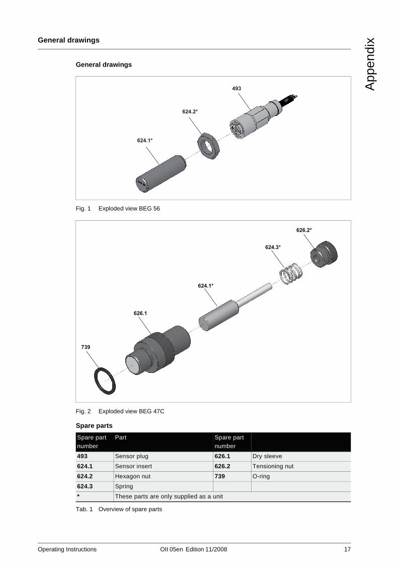
Appendix General drawings
Spare parts
Tab. 1 Overview of spare parts
Fig. 1 Exploded view BEG 56
Fig. 2 Exploded view BEG 47C
Spare part number
Part Spare part number
493 Sensor plug 626.1 Dry sleeve
624.1 Sensor insert 626.2 Tensioning nut
624.2 Hexagon nut 739 O-ring
624.3 Spring
* These parts are only supplied as a unit
624.1*
624.2*
493
739
626.1
624.1*
624.3*
626.2*

18 OII 05en Edition 11/2008 Operating Instructions
Notes
App
endi
x
Notes

Operating Instructions OII 05en Edition 11/2008 19
Notes
App
endi
x

KRAL AG, Bildgasse 40, Industrie Nord, 6890 Lustenau, Austria,Tel.: +43 / 55 77 / 8 66 44 - 0Fax: +43 / 55 77 / 8 84 33, www.kral.at, E-Mail: [email protected]