Embed Size (px)
Citation preview
KR CNC GROOVE DRESSING MACHINE New generation of roll groove dressing machines
GROOVE DRESSING MACHINES Free configuration of groove forms
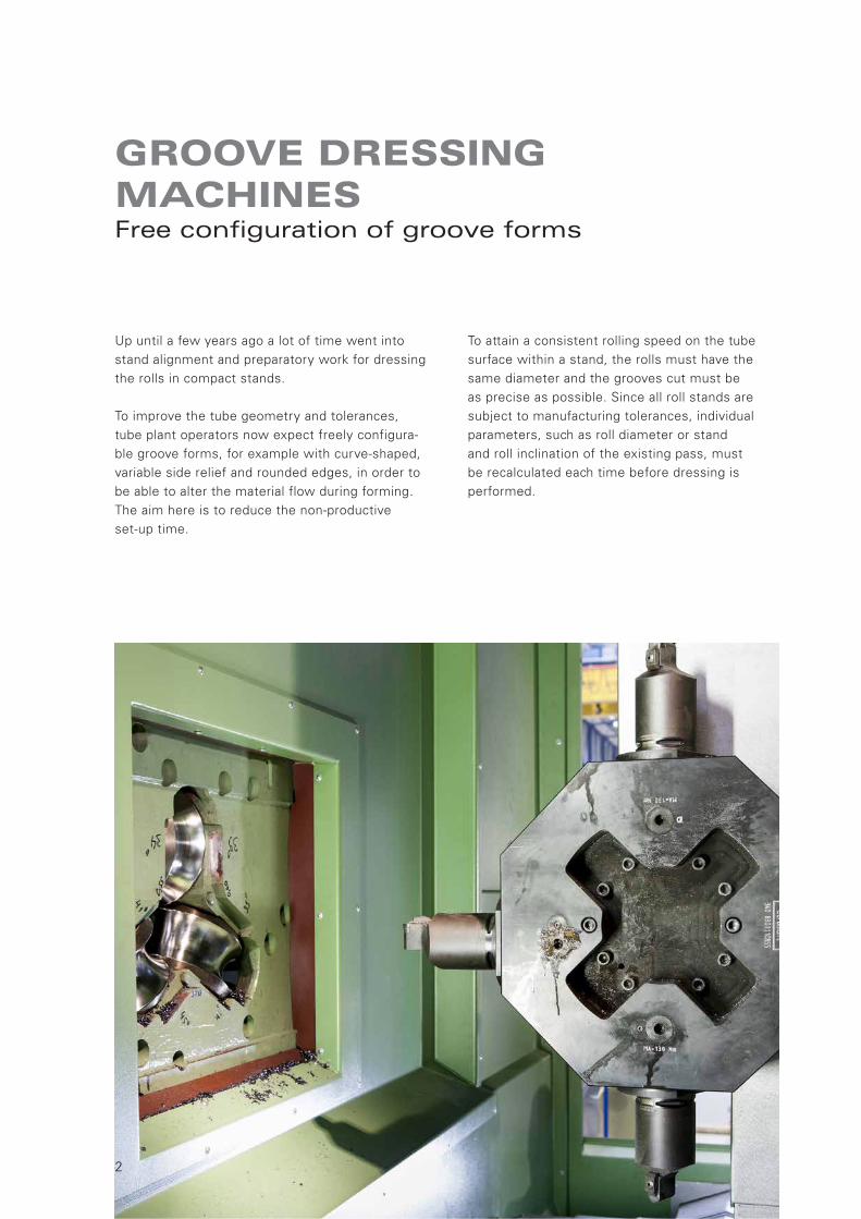
Up until a few years ago a lot of time went into stand alignment and preparatory work for dressing the rolls in compact stands.
To improve the tube geometry and tolerances, tube plant operators now expect freely configura-ble groove forms, for example with curve-shaped, variable side relief and rounded edges, in order to be able to alter the material flow during forming. The aim here is to reduce the non-productive set-up time.
To attain a consistent rolling speed on the tube surface within a stand, the rolls must have the same diameter and the grooves cut must be as precise as possible. Since all roll stands are subject to manufacturing tolerances, individual parameters, such as roll diameter or stand and roll inclination of the existing pass, must be recalculated each time before dressing is performed.
2

3
ROLL GROOVE DRESSING MACHINES Computer-controlled processing sequence
With its KR CNC series the SMS group has develo-ped a new generation of roll groove dressing machi-nes for stretch-reducing, sizing and push bench roll stands. The developers were able to benefit from the positive experience they had with the GG 52 CNC grinding machine.
The new machine is equipped with a measuring device that records the roll positions and the groove contours to be machined under automatic program control and transfers the data to a computer program. The computer then controls the subsequent proces-sing sequence based on these current measured values.
The three rolls are machined one after the other at the front end of the stand. The cutting tool holders – which are separate for each roll – and the sensor are fitted on a pivoted disk turret equipped with a quick-change system. Ceramic or CBN is used as the cutting material.
When designing the individual machine assemblies, the calculations were checked by the Laboratory for Machine Tools and Production Engineering at RWTH Aachen University. The high degree of machine sta-bility and freedom from vibrations were extensively tested in a load simulation.

AUTOMATIC MEASURING SYSTEMThe easy way to produce any groove form
With the triple-axis loop control system and the higher-level measuring data computer you can have any groove design you wish – round, oval or round with parabolic side zones. In this way, the roll pass operator can freely configure the grooves and optimise the groove shaping process. With these configuration options the polygon effect that occurs inside the tube during stretch-reducing can be reduced or even avoided completely. Changes to the groove parameters can be made easily by quickly re-programming the system.
An automatic measuring cycle records the current groove diameter, the roll diameter in the groove root and the roll axis inclination in increments. The measuring data recorded are collected by the computer program and processed for machining purposes.
Subsequent machining starts with roughing, each time from the roll edge to the roll base. Once intermediate measurements and any necessary corrections have been performed, finishing takes place in one pass, including rounding-off of the groove edges.
FULLY AUTOMATIC MACHINING
The machining cycle described takes around 30 minutes for a stand with 300 mm roll diameters. Cutting speeds of up to 200 m/min can be used. To ensure the data are optimally documented, the groove profile cut can be measured using the built-in measuring device and then printed off.
A shop crane is used to lower the stands to be ma-chined onto the loading table. A draw-in device brings the stand into the machining position. There the stand
4

5
is hydraulically clamped. The machine is automated to such an extent that the operator is able to concen-trate on inputting the groove data and stand numbers. The entire machining sequence between „Load unmachined stand“ and „Remove finished stand“ is performed fully automatically.
This series includes machinery that can machine the roll stands with or more drive units. The machines can also be adapted for use with stands from other rolling mill manufacturers.
LOADING CYCLE IN FIVE STEPS
1 New stand to be machined is placed on the loading table2 The finish-machined stand is removed from the machine3 The finish-machined stand is moved to the unloading/
changing position4 The new stand to be machined is moved into the run-in
position in front of the machine5 The new stand to be machined is run into the machine
(machining position)
1
2
3
4
5
6
GROOVE DRESSINGGroove forms cut quickly and precisely
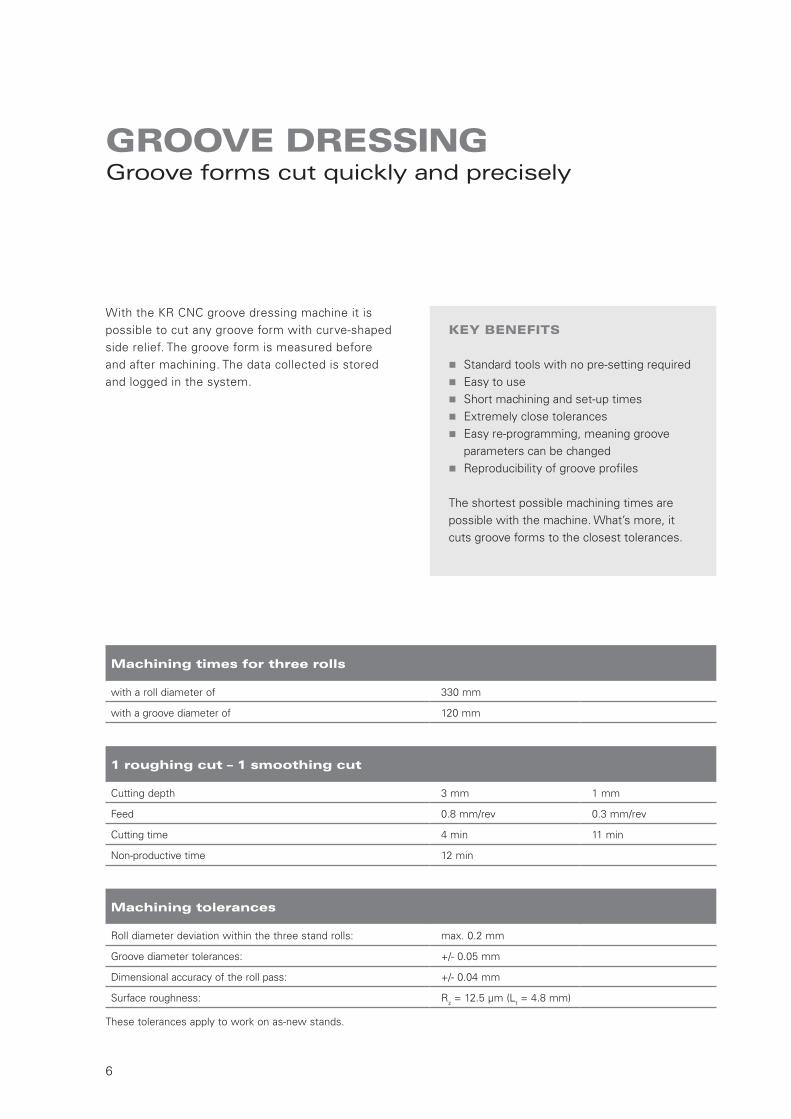
With the KR CNC groove dressing machine it is possible to cut any groove form with curve-shaped side relief. The groove form is measured before and after machining. The data collected is stored and logged in the system.
KEY BENEFITS
� Standard tools with no pre-setting required � Easy to use � Short machining and set-up times � Extremely close tolerances � Easy re-programming, meaning groove
parameters can be changed � Reproducibility of groove profiles
The shortest possible machining times are possible with the machine. What’s more, it cuts groove forms to the closest tolerances.
1 roughing cut – 1 smoothing cut
Cutting depth 3 mm 1 mm
Feed 0.8 mm/rev 0.3 mm/rev
Cutting time 4 min 11 min
Non-productive time 12 min
Machining times for three rolls
with a roll diameter of 330 mm
with a groove diameter of 120 mm
Machining tolerances
Roll diameter deviation within the three stand rolls: max. 0.2 mm
Groove diameter tolerances: +/- 0.05 mm
Dimensional accuracy of the roll pass: +/- 0.04 mm
Surface roughness: Rz = 12.5 μm (Lt = 4.8 mm)
These tolerances apply to work on as-new stands.
7
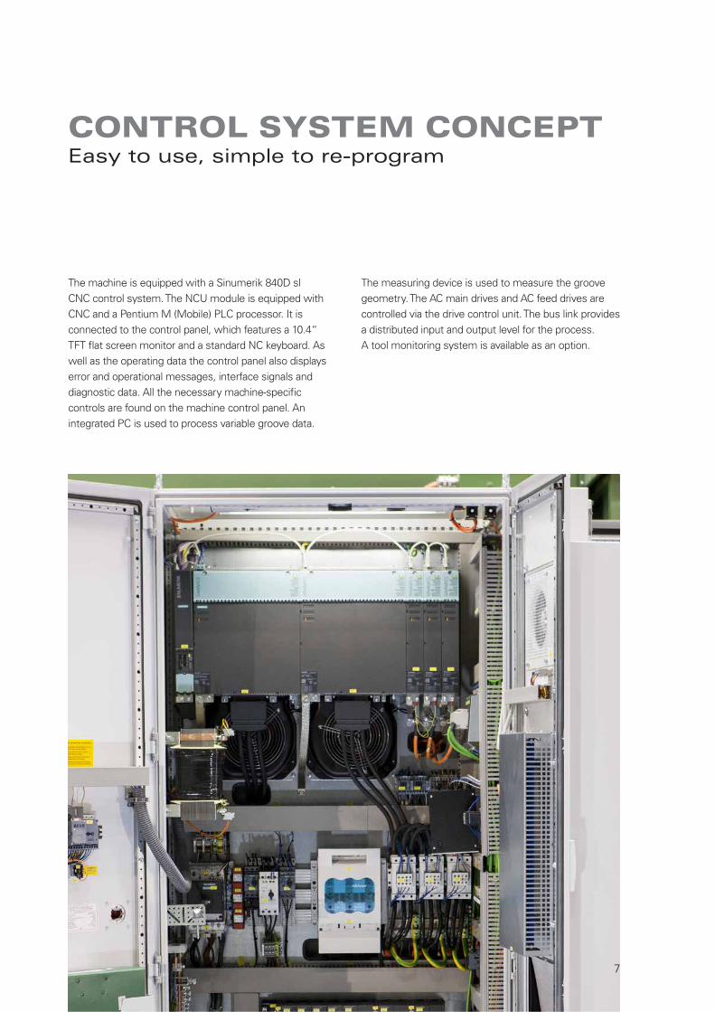
The machine is equipped with a Sinumerik 840D sl CNC control system. The NCU module is equipped with CNC and a Pentium M (Mobile) PLC processor. It is connected to the control panel, which features a 10.4“ TFT flat screen monitor and a standard NC keyboard. As well as the operating data the control panel also displays error and operational messages, interface signals and diagnostic data. All the necessary machine-specific controls are found on the machine control panel. An integrated PC is used to process variable groove data.
The measuring device is used to measure the groove geometry. The AC main drives and AC feed drives are controlled via the drive control unit. The bus link provides a distributed input and output level for the process. A tool monitoring system is available as an option.
CONTROL SYSTEM CONCEPTEasy to use, simple to re-program

C12
04.1
2/15
de
· Prin
ted
in G
erm
any
SMS GROUP GMBH
Business Unit Tube and Pipe Plants
Ohlerkirchweg 66
41069 Mönchengladbach
Germany
Phone: +49 2161 350-1318
Fax: +49 2161 350-1851
www.sms-group.com
The information provided in this brochure contains a general description of the performance characteristics of the products concerned. The actual products may not always have these characteristicsas described and, in particular, these may change as a result of further developments of the products. The provision of this information is not intended to have and will not have legal effect. An obligationto deliver products having particular characteristics shall only exist if expressly agreed in the terms of the contract.