Embed Size (px)
Citation preview
ELECRAFT KPA1500
1500-WATT AMPLIFIER
OWNER’S MANUAL
Revision B, May 16, 2018
E740301
Copyright © 2018, Elecraft, Inc.
All Rights Reserved

2
Introduction
On behalf of our entire design team, we’d like to thank you for choosing the Elecraft KPA1500 amplifier.
The KPA1500 offers a unique combination of features. It’s one of the smallest 1500W amplifiers available. The
power supply is in a separate enclosure for ease of station layout.
The KPA1500 is capable of fully automatic operation, yet has an alphanumeric display and a full complement of
front panel switches for precise manual control. A comprehensive remote-control command set is also included.
The KPA1500 can be used with nearly any transceiver, thanks to its instantaneous RF-based band switching,
advanced protection circuitry, adjustable ALC, and extensive parametric monitoring. It also has inputs that
allow direct band switching from many popular transceivers. TR is completely noise-free thanks to the use of
PIN-diode switching.
The KPA1500 comes with a built-in Automatic Antenna Tuner (ATU) that can handle a load SWR up to 3:1 at
the full 1500 watt output in any mode.
Of course, the KPA1500 is an ideal companion for the Elecraft K3S and K3 transceivers, both physically and
electrically. The Elecraft K3S or K3 can sense whether the amp is in standby or operate mode, then select the
appropriate per-band power settings. This allows you to set up the K3S or K3 for “barefoot” operation at one
power level on each band, and then switch the amp to operate and set up optimal drive levels for full 1500W
output. The K3/KPA1500 combination is also capable of extremely fast break-in, especially when the K3S or
K3 is placed in QRQ (high-speed CW) mode. The two are so well-integrated that you can use the per-band
switches on the amplifier to change bands at the transceiver.
If you use the KPA1500 with both the K3S or K3 transceiver and P3 panadapter – our new “K-Line” – you’ll
enjoy a high degree of operating convenience, along with world-class performance and the power to get the job
done.
73,
Wayne, N6KR
Eric, WA6HHQ
3
Contents
Introduction ............................................................................................................................................... 2
FCC-Mandated Part 15 Notice for the Computer Interface Ports ............................................................ 6
In the Box ................................................................................................................................................. 6
Installation ................................................................................................................................................ 7
Positioning the KPA1500 RF Deck and Power Supply ...................................................................................... 9
Cabling – Power Supply ...................................................................................................................................... 9
Cabling – RF Deck .............................................................................................................................................. 9
Operation ................................................................................................................................................ 14
RF Deck Front Panel Controls .......................................................................................................................... 14
Power On ........................................................................................................................................................... 15
Band Switching ................................................................................................................................................. 15
Antenna Selection ............................................................................................................................................. 16
Transmitting ...................................................................................................................................................... 16
Using Automatic Level Control (ALC) ............................................................................................................. 17
Automatic Antenna Tuner (ATU) ..................................................................................................................... 18
Amplifier Monitoring and Status Indicators ..................................................................................................... 21
Remote Operation ............................................................................................................................................. 23
Fault Conditions ................................................................................................................................................ 24
KPA1500 Utility Program ...................................................................................................................... 29
KPA1500 Firmware Updates ............................................................................................................................ 29
Checking your Firmware Version ..................................................................................................................... 29
Forcing a Firmware Load .................................................................................................................................. 29
Wattmeter Calibration Procedure ........................................................................................................... 30
Specifications .......................................................................................................................................... 31
Customer Service and Support ............................................................................................................... 33
4
Theory of Operation ............................................................................................................................... 34
AUX and XCVR Serial Connector Interfaces ........................................................................................ 37
KPA1500 AUX Connector Pinout (DE-15 Male) ............................................................................................. 37
Elecraft KPAK3AUX Interface Cable .............................................................................................................. 38
Icom Transceiver Interfacing ............................................................................................................................ 38
XCVR SERIAL Cable ...................................................................................................................................... 39
TUNE Cable ...................................................................................................................................................... 40
CW Key Tune Cable ......................................................................................................................................... 41
Yaesu Transceivers ........................................................................................................................................... 42
BCD Interface ................................................................................................................................................... 43
Kenwood Transceivers ...................................................................................................................................... 43
Flex Transceivers .............................................................................................................................................. 43
In Case of Difficulty ............................................................................................................................... 44
Appendix A—KPA1500 Tuner Frequency Segments ............................................................................ 45
Elecraft manuals with color images may be downloaded from www.elecraft.com.
5
WARNING
Dangerous Voltages are Present Inside the KPA1500 and its
Power Supply
Do not turn on or operate the amplifier or power supply with
the covers off.
Before opening the KPA1500 RF Deck or Power Supply
enclosures:
1. Turn off the KPA1500 by tapping the front panel ON
switch and wait until the fan stops. (The fan drains
the power supply to a safe voltage.)
2. Turn off the power supply breaker switch (on the rear
panel).
3. Disconnect the two Power Supply cables at RF Deck
rear panel before opening the RF Deck enclosure.
4. Disconnect the Power Supply from the mains before
opening the cover.
Key to Symbols, Abbreviations and Text Styles
Important – read carefully
Operating tip
TEMP Tap switch function (labeled above a switch; press for less than 1/2 second)
PK HOLD Hold switch function (labeled below a switch; press for at least 1/2 sec. to
activate)
INHIBIT Typical text appearing on the LCD.
LED Light Emitting Diode
LCD Liquid Crystal Display
CAUTION
Follow the instructions under a Caution to avoid damage to the equipment.
WARNING
Follow the instructions under a Warning to avoid serious personal injury.
6
FCC-Mandated Part 15 Notice for the Computer Interface Ports
This equipment has been tested and found to comply with the limits for a Class B digital device, pursuant to part
15 of the FCC Rules. These limits are designed to provide reasonable protection against harmful interference in
a residential installation. This equipment generates, uses and can radiate radio frequency energy and, if not
installed and used in accordance with the instructions, may cause harmful interference to radio communications.
However there is no guarantee that interference will not occur in a particular installation. If this equipment does
cause harmful to radio or television reception, which can be determined by turning the equipment off and on, the
user is encouraged to try to correct the interference by one or more of the following measures:
• Reorient or relocate the receiving antenna.
• Increase the separation between the equipment and receiver.
• Connect the equipment to an outlet on a different circuit from that to which the receiver is connected.
• Consult the dealer or an experienced radio/TV technician for help.
Regarding the computer interface: changes or modifications not expressly approved by Elecraft could void the
user’s authority to operate the equipment.
Elecraft Inc.
125 Westridge Dr.
Watsonville, CA 95076
+1 (831) 763-4211
www.elecraft.com
In the Box
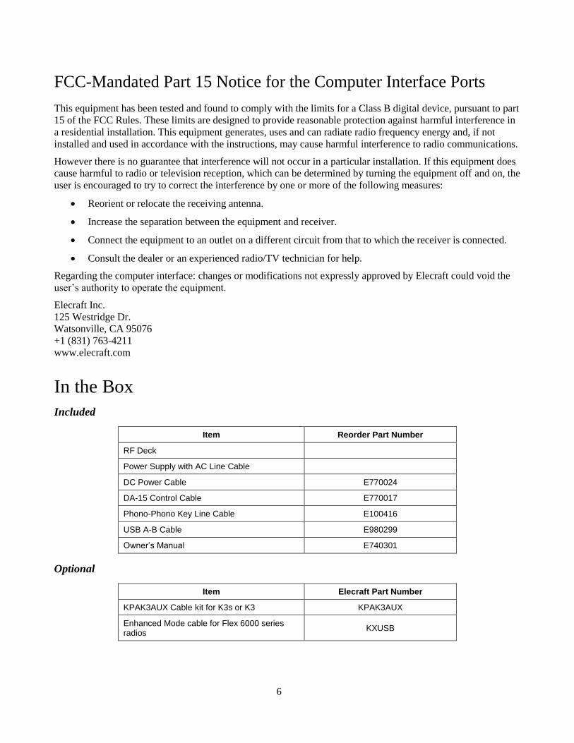
Included
Item Reorder Part Number
RF Deck
Power Supply with AC Line Cable
DC Power Cable E770024
DA-15 Control Cable E770017
Phono-Phono Key Line Cable E100416
USB A-B Cable E980299
Owner’s Manual E740301
Optional
Item Elecraft Part Number
KPAK3AUX Cable kit for K3s or K3 KPAK3AUX
Enhanced Mode cable for Flex 6000 series radios
KXUSB
7
Installation
Installation consists of the following:
• Positioning the KPA1500 RF Deck and Power Supply to provide for proper cooling, see page 9.
• Connecting the KPA1500 RF Deck and Power Supply, page 9.
• Cabling the KPA1500 RF Deck to your other station equipment, page 9.
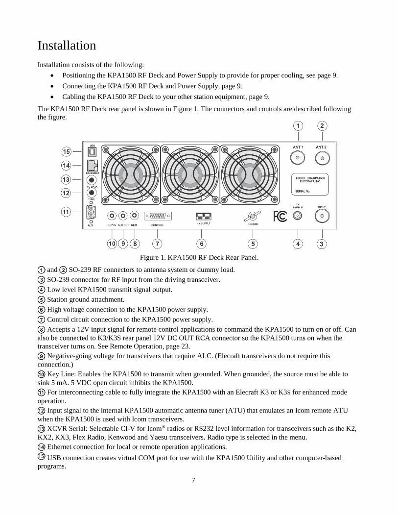
The KPA1500 RF Deck rear panel is shown in Figure 1. The connectors and controls are described following
the figure.
Figure 1. KPA1500 RF Deck Rear Panel.
and SO-239 RF connectors to antenna system or dummy load.
SO-239 connector for RF input from the driving transceiver.
Low level KPA1500 transmit signal output.
Station ground attachment.
High voltage connection to the KPA1500 power supply.
Control circuit connection to the KPA1500 power supply.
Accepts a 12V input signal for remote control applications to command the KPA1500 to turn on or off. Can
also be connected to K3/K3S rear panel 12V DC OUT RCA connector so the KPA1500 turns on when the
transceiver turns on. See Remote Operation, page 23.
Negative-going voltage for transceivers that require ALC. (Elecraft transceivers do not require this
connection.)
Key Line: Enables the KPA1500 to transmit when grounded. When grounded, the source must be able to
sink 5 mA. 5 VDC open circuit inhibits the KPA1500.
For interconnecting cable to fully integrate the KPA1500 with an Elecraft K3 or K3S for enhanced mode
operation.
Input signal to the internal KPA1500 automatic antenna tuner (ATU) that emulates an Icom remote ATU
when the KPA1500 is used with Icom transceivers.
XCVR Serial: Selectable CI-V for Icom® radios or RS232 level information for transceivers such as the K2,
KX2, KX3, Flex Radio, Kenwood and Yaesu transceivers. Radio type is selected in the menu.
Ethernet connection for local or remote operation applications.
USB connection creates virtual COM port for use with the KPA1500 Utility and other computer-based
programs.
8
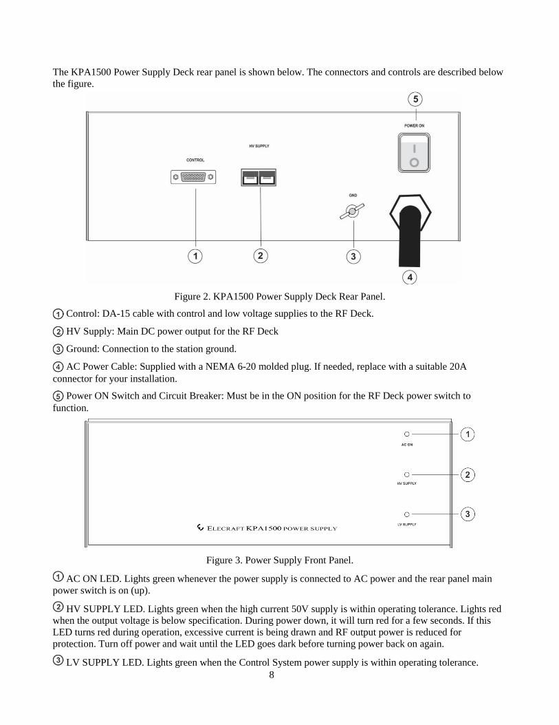
The KPA1500 Power Supply Deck rear panel is shown below. The connectors and controls are described below
the figure.
Figure 2. KPA1500 Power Supply Deck Rear Panel.
Control: DA-15 cable with control and low voltage supplies to the RF Deck.
HV Supply: Main DC power output for the RF Deck
Ground: Connection to the station ground.
AC Power Cable: Supplied with a NEMA 6-20 molded plug. If needed, replace with a suitable 20A
connector for your installation.
Power ON Switch and Circuit Breaker: Must be in the ON position for the RF Deck power switch to
function.
Figure 3. Power Supply Front Panel.
AC ON LED. Lights green whenever the power supply is connected to AC power and the rear panel main
power switch is on (up).
HV SUPPLY LED. Lights green when the high current 50V supply is within operating tolerance. Lights red
when the output voltage is below specification. During power down, it will turn red for a few seconds. If this
LED turns red during operation, excessive current is being drawn and RF output power is reduced for
protection. Turn off power and wait until the LED goes dark before turning power back on again.
LV SUPPLY LED. Lights green when the Control System power supply is within operating tolerance.
9
Positioning the KPA1500 RF Deck and Power Supply
Provide at least 4” (10 cm) clearance behind the RF Deck fans and above the Power Supply top cover. Allow at
least 1” (2.5 cm) clearance around the top and sides of the RF Deck and around the sides of the Power Supply
for normal cooling air flow.
The supplied cables allow the Power Supply and RF Deck to be placed up to 66” (167 cm) apart. The Power
Supply can be operated remotely so there is no need for it to be within the operator’s reach. The fans operate
whenever the KPA1500 is on, so you can place the Power Supply under the operating desk or elsewhere to
minimize fan noise.
Cabling – Power Supply
Be sure the POWER ON switch is off before connecting any cables to the Power Supply or RF Deck.
An AC power cable with the popular NEMA 6-20 connector is supplied attached to the Power Supply. The
NEMA 6-20 connector is compatible with NEMA 6-20R receptacles. Replace the connector if you need a
different connection to your mains supply. Elecraft recommends a 200/240 volt AC, 20 amp circuit for proper
operation of the KPA1500.
Connect the Power Supply to the RF Deck with the supplied 66” (167 cm) cable. Plug the Anderson
PowerPole® connector into the HV Supply connector on the RF Deck rear panel (Figure 1, page 7) and the
corresponding connector on the Power Supply , Figure 2, page 8. Observe the polarity; match the colors on
the plug with the connectors.
The 75A PowerPole connectors click twice when inserted. There is no electrical connection until the
second “click.”
Connect the 15-pin connector to the Power Supply and the Control connector on the RF Deck rear panel.
Ensure the captive screws securing the connectors are tight and the connectors are fully seated.
Cabling – RF Deck
Always turn the KPA1500 off via the rear panel switch/circuit breaker on the Power
Supply before attaching or removing cables.
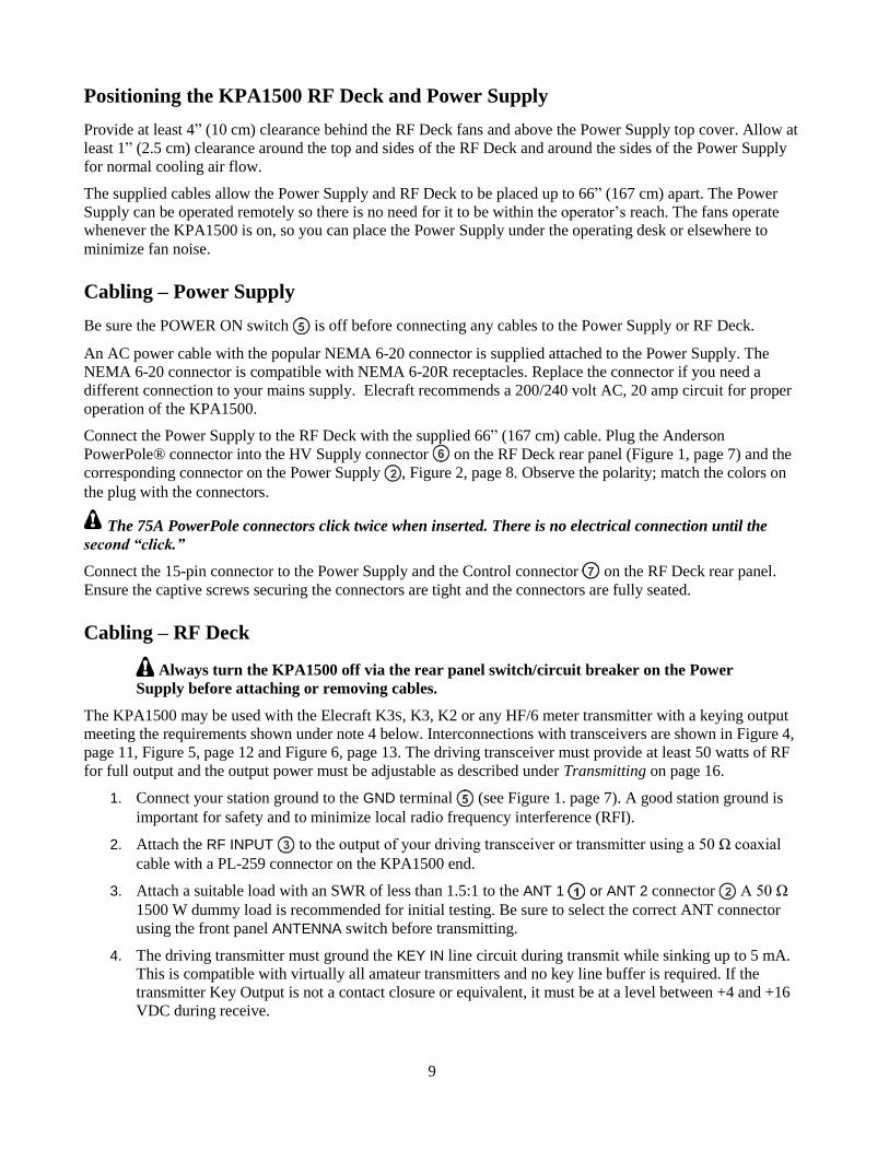
The KPA1500 may be used with the Elecraft K3S, K3, K2 or any HF/6 meter transmitter with a keying output
meeting the requirements shown under note 4 below. Interconnections with transceivers are shown in Figure 4,
page 11, Figure 5, page 12 and Figure 6, page 13. The driving transceiver must provide at least 50 watts of RF
for full output and the output power must be adjustable as described under Transmitting on page 16.
1. Connect your station ground to the GND terminal (see Figure 1. page 7). A good station ground is
important for safety and to minimize local radio frequency interference (RFI).
2. Attach the RF INPUT to the output of your driving transceiver or transmitter using a 50 Ω coaxial
cable with a PL-259 connector on the KPA1500 end.
3. Attach a suitable load with an SWR of less than 1.5:1 to the ANT 1 or ANT 2 connector A 50 Ω
1500 W dummy load is recommended for initial testing. Be sure to select the correct ANT connector
using the front panel ANTENNA switch before transmitting.
4. The driving transmitter must ground the KEY IN line circuit during transmit while sinking up to 5 mA.
This is compatible with virtually all amateur transmitters and no key line buffer is required. If the
transmitter Key Output is not a contact closure or equivalent, it must be at a level between +4 and +16
VDC during receive.

10
Enhanced Mode Operation with a K3 or K3S
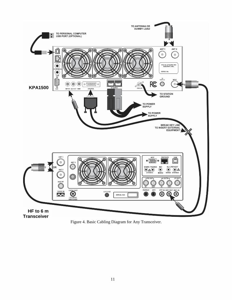
The optional KPAK3AUX cable kit provides closer integration with a K3 or K3S by sharing band information
between the KPA1500 and the transceiver, see Figure 5, page 12 and Figure 6, page 13. The KPAK3AUX cable
kit enables all enhanced features described under Operation, including coordinated band-switching (page 15).
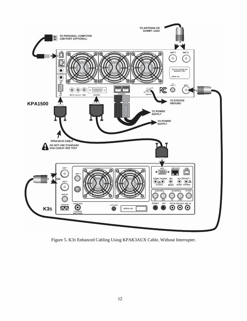
The KPAK3AUX cable kit also incorporates the KEY IN line. If you need access to this line so that other
equipment can bypass the amplifier, you can install the Key Line Interrupter supplied with your KPAK3AUX
cable and use a separate key line as shown in Figure 6 on page 13.
You must use the Key Line Interrupter when using a separate key line with the
KPAK3AUX cable kit. Otherwise any external equipment inserted into the key line will not
be able to inhibit the amplifier.
Cables for Yaesu and Icom transceivers to provide closer integration with the KPA1500 are available.
See AUX and XCVR Serial Connector Interfaces on page 37.
11
Figure 4. Basic Cabling Diagram for Any Transceiver.
KPA1500
HF to 6 m Transceiver
12
Figure 5. K3S Enhanced Cabling Using KPAK3AUX Cable, Without Interrupter.
KPA1500
K3S
13
Figure 6. K3S Enhanced Cabling Using KPAK3AUX Cable and Separate Key Line, With Interrupter.
K3S
KPA1500
14
Operation
RF Deck Front Panel Controls
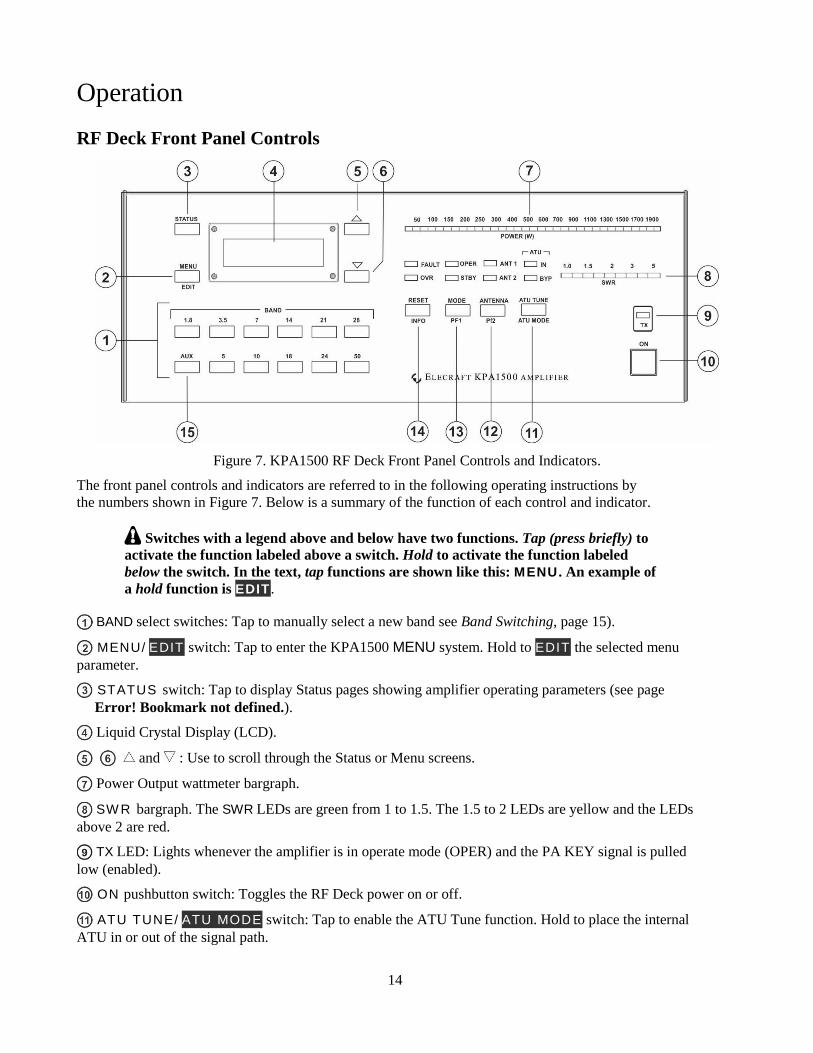
Figure 7. KPA1500 RF Deck Front Panel Controls and Indicators.
The front panel controls and indicators are referred to in the following operating instructions by
the numbers shown in Figure 7. Below is a summary of the function of each control and indicator.
Switches with a legend above and below have two functions. Tap (press briefly) to
activate the function labeled above a switch. Hold to activate the function labeled
below the switch. In the text, tap functions are shown like this: MENU . An example of
a hold function is EDIT .
BAND select switches: Tap to manually select a new band see Band Switching, page 15).
MENU/ EDIT switch: Tap to enter the KPA1500 MENU system. Hold to EDIT the selected menu
parameter.
STATUS switch: Tap to display Status pages showing amplifier operating parameters (see page
Error! Bookmark not defined.).
Liquid Crystal Display (LCD).
and : Use to scroll through the Status or Menu screens.
Power Output wattmeter bargraph.
SW R bargraph. The SWR LEDs are green from 1 to 1.5. The 1.5 to 2 LEDs are yellow and the LEDs
above 2 are red.
TX LED: Lights whenever the amplifier is in operate mode (OPER) and the PA KEY signal is pulled
low (enabled).
ON pushbutton switch: Toggles the RF Deck power on or off.
ATU TUNE/ ATU MODE switch: Tap to enable the ATU Tune function. Hold to place the internal
ATU in or out of the signal path.
15
ANTENNA / PF2 switch: Tap to toggle between the ANT1 and ANT2 outputs. Hold to select user-
programmable function 2, (future feature).
MODE / PF1 switch: Tap to switch between Operate (OPER) and Standby (STBY) modes. Hold to
select user-programmable function 1, (future feature).
RESET / INFO switch: Tap to reset a fault condition. Hold to display information about the last fault
on the LCD.
AUX switch: Hold for 10 seconds to force a firmware load (see page 29).
Power On
IMPORTANT
When the KPA1500 is turned off using the front-panel switch , part of the control circuitry
remains on as long as AC mains power is applied to the Power Supply.
Keeping the control circuitry energized allows the KPA1500 to be turned on and off remotely as well as
from the front-panel switch. If you do not need to control the KPA1500 remotely and would prefer to
save the small amount of power required to power the control circuitry, either switch the Power Supply
completely off or provide an external mains power switch capable of handling 20A.
1. Ensure a suitable 50 Ω load is attached to the ANT 1 or ANT 2 connector on the rear panel. Tap
the front panel ANTENNA switch to select the antenna connector used. The associated LED will
be illuminated. A dummy load is recommended for initial tests.
2. Enable the power supply by placing the rocker switch on the power supply module in the ON (I) position.
3. Tap the ON switch . The LCD , ANT 1 or ANT 2 and the OPER or STBY LEDs should light. By
default the KPA1500 enters Standby mode (STBY) at power on. You can change the default to start in
OPER mode using the POWER ON MODE menu item, see page 28.
If the FAULT LED lights at any time, refer to Fault Conditions, page 24.
Band Switching
Band switching may be done automatically or manually as follows:
Automatic Band Switching via Frequency Counter: The KPA1500 measures the incoming RF frequency and
automatically selects the proper band. The KEY IN input must be connected to the driving transmitter to enable
the KPA1500’s counter.
The automatic band selection via frequency counter is active whenever the KEY IN is
low (transmit mode) and the transceiver is delivering RF drive to the KPA1500. The
automatic band selection function overrides band selection made by any other means to
protect the KPA1500 from damage by wrong-band operation.
Manual Band Switching: Tap any of the front-panel BAND switches to manually switch the KPA1500
to that band. If the incorrect band is selected, the built-in frequency counter will automatically select the
proper band for the RF frequency presented to the Input.
Coordinated K3S or K3 and KPA1500 Band Switching: When the optional AUX cable (page 10) is
connected between the KPA1500 and the K3S or K3:
• The KPA1500 will follow the band selected on a K3S or K3 transceiver without the need
to transmit.
16
• Tapping a BAND switch on the KPA1500 will cause the K3S or K3 to change bands
accordingly.
The KPA1500 can automatically follow band selection from certain non-Elecraft transceivers
such as Flex Radio, Icom and Yaesu (BCD) without transmitting when the appropriate control
cable is used. This is called Enhanced Mode operation.
However, control is one-way: The KPA1500 cannot command the transceiver to change bands as
it does when connected to a K3S or K3 with the optional AUX cable.
See AUX and XCVR Serial Connector Interface on page 37.
Antenna Selection
Tap ANTENNA to select the desired rear panel antenna connector. Either ANT 1 or ANT 2 LED illuminates to
indicate the selection.
You may designate either ANT1 or ANT2 on a per-band basis. By default, the KPA1500 will return to that
choice when returning to that band. You can configure this function with the KPA1500 Utility Configuration
panel.
You can also disable one of the antenna outputs for selected bands. See ANTENNA ENABLE and ANTENNA
PREFER entries under Menu on page 25. The KPA1500 Utility Configuration section makes it easy to configure
this function.
• If an ANT connector is disabled on any band, tapping the ANT button blinks the ANT LED, but
will not change to the disabled antenna.
When the KPA1500 is powered off, the Input port is connected directly to the ANT1 port, even if ANT1 is
disabled.
Transmitting
The POWER (W) and standing wave ratio (SWR) bargraphs are functional when the amplifier is in
standby (STBY). Twenty five watts from the driving transceiver will illuminate the first POWER LED.
You may run up to 200 watts through the KPA1500 in STANDBY.
If you attempt to drive the KPA1500 on a frequency that is more than 100 kHz
outside of an Amateur band or in the range of 26 to 28 MHz, the KPA1500
automatically switches to standby, the red FAULT LED lights and a tone is sounded
in the speaker.
1. Be sure you have an antenna or dummy load connected to the active antenna output (see Antenna
Selection above) and your driving transceiver is on a frequency inside an Amateur band.
2. In order for the KPA1500 to amplify, it must be in OPER mode and it must be keyed. The
amplifier can be keyed either by KEY IN pulled low or using the optional KPAK3AUX cable
connected to the K3/K3S.
3. If you have a 50 Ω dummy load or an antenna that you know presents a low SWR to the
KPA1500, press and hold the ATU MODE switch to put the ATU in bypass (BYP LED lights).
If you are not sure of the SWR, press and hold the ATU MODE switch to enable the ATU (IN
LED lights).
4. Tap the MODE switch as needed so the OPER LED lights.
5. Apply a few watts of RF drive and watch the POWER (W) bargraph illuminate to indicate RF
output power.
17
6. Normal drive levels to produce the full 1500 W output will be about 50 W, but start with a much
lower level to observe how the KPA1500 behaves.
7. Slowly increase the drive power and confirm the SWR bargraph indicates less than 1.5 while
the output indicated by the POWER (W) bargraph increases.
If your load presents a high SWR, be sure the ATU is enabled (press the ATU MODE switch to
light the IN LED), and then tap ATU TUNE to initiate a tuning cycle. Apply 25 to 50 W of
transmitter drive during this tune cycle. About 50 W of drive is required to produce the full 1500
W output from the KPA1500.
During heavy use, you may hear clicking sounds as amplifier components cool. This is
normal. It does not indicate the amplifier is being over stressed. The rear panel fans will
turn on and increase speed as needed automatically. If desired, you can keep the fans
running at all times using the FAN SPEED MIN menu setting (see Menu Section starting on
page 25).
8. When driving the KPA1500 with an Elecraft K3 or K3S, use the per-band power control to set the
amplifier output just below the desired peak output on each band. Do not rely on ALC to control
the power output (see Using ALC, page 17).
In the K3 or K3S, program CONFIG:POWER SET to Per Band and adjust the power level for
each band. See Per-Band Power Control in your K3 or K3S Owner’s Manual for further details.
(Requires K3 firmware version 4.82 or later).
If you use the AUX cable interface between the K3 or K3S and KPA1500 (Figure 5, page
12 or Figure 6, page 13), and you have RADIO TYPE set to K3 or K3s, the KPA1500 will
send the operate/standby status to the K3 or K3S.
This means you can set two per-band power levels with the K3 or K3S:
One to drive the KPA1500 when it is in operate mode and another for pass-through transmitting when
the KPA1500 is in standby. The K3 or K3S will automatically return to your preset power levels as you
switch the KPA1500 between operate and standby.
Using Automatic Level Control (ALC)
Automatic Level Control (ALC) is a useful safety mechanism, but do not use ALC as the principle power
control. Doing so causes many of the unwanted transmit dynamics you often hear on the air including excessive
intermodulation distortion (IMD) and clicks.
Elecraft recommends using the K3 or K3S PWR SET-PER BAND function to set proper drive levels, not ALC.
The Elecraft K3 and K3S ALC intentionally have a slow attack and much slower decay to avoid adding more
distortion or dynamics problems than necessary. However, not all of the negative effects of ALC action can be
avoided. It is still best to set the ALC threshold and then adjust the drive to avoid ALC action in normal
operation.
If you chose to use ALC, set your transmitter power output correctly as described under Transmitting and adjust
the ALC so it does not affect output power in normal operation.
1. Drive the KPA1500 to the desired output.
2. Adjust ALC THRESH in the menu (page 25) until power just starts to drop and then set ALC THR one
or two units above this setting so it does not affect the output power in normal operation.
3. Repeat on each band. ALC THRESH is set and saved separately on each band.
18
Automatic Antenna Tuner (ATU)
The internal ATU may be used with the KPA1500 in either standby or operate mode. When the KPA1500 is in
standby mode, power from the driving transceiver is passed directly to the ATU. Press and hold ATU MODE to
select whether the ATU is active (IN) or bypassed (BYP). The corresponding LED above the switch will light.
The maximum bypass power through the KPA1500 INPUT connector is 200 W.
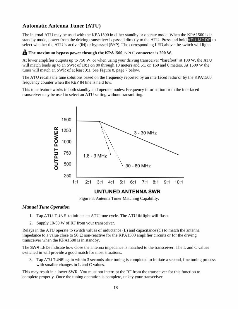
At lower amplifier outputs up to 750 W, or when using your driving transceiver “barefoot” at 100 W, the ATU
will match loads up to an SWR of 10:1 on 80 through 10 meters and 5:1 on 160 and 6 meters. At 1500 W the
tuner will match an SWR of at least 3:1. See Figure 8, page 7 below.
The ATU recalls the tune solutions based on the frequency reported by an interfaced radio or by the KPA1500
frequency counter when the KEY IN line is held low.
This tune feature works in both standby and operate modes: Frequency information from the interfaced
transceiver may be used to select an ATU setting without transmitting.
Figure 8. Antenna Tuner Matching Capability.
Manual Tune Operation
1. Tap ATU TUNE to initiate an ATU tune cycle. The ATU IN light will flash.
2. Supply 10-50 W of RF from your transceiver.
Relays in the ATU operate to switch values of inductance (L) and capacitance (C) to match the antenna
impedance to a value close to 50 Ω non-reactive for the KPA1500 amplifier circuits or for the driving
transceiver when the KPA1500 is in standby.
The SWR LEDs indicate how close the antenna impedance is matched to the transceiver. The L and C values
switched in will provide a good match for most situations.
3. Tap ATU TUNE again within 3 seconds after tuning is completed to initiate a second, fine tuning process
with smaller changes in L and C values.
This may result in a lower SWR. You must not interrupt the RF from the transceiver for this function to
complete properly. Once the tuning operation is complete, unkey your transceiver.
19
If the SWR is 1.2 or less when a tune operation begins, the KPA1500 bypasses the matching network without
searching for a tuning solution. The ATU IN and the ATU BYP LEDs both illuminate to show the tuner is
bypassed for this frequency. When returning to the selected frequency, the internal ATU will recall the bypass
mode. The ATU IN and the ATU BYP LEDs will be illuminated again when this happens.
You can change the default bypass SWR threshold with the ATU BYPASS parameter in the Menu. Subsequent
ATU TUNE procedures will use the new threshold to determine when the internal ATU is placed into Bypass
mode.
ATU Memories
After successfully tuning, the KPA1500 stores L and C or Bypass settings and the ANT1 or ANT2 selection in
memory. They are recalled when returning to that frequency.
The entire spectrum from 1.8 through 60 MHz is divided into frequency segments and tuning information is
stored for each successfully tuned segment. These are called memory “bins.” Please see the Appendix, page 45
for a list of the center frequencies of each of the memory bins.
Re-tuning to maintain a low SWR is normally required over a narrower frequency range on the lower
frequencies, so lower frequencies have narrower segments assigned as follows:
• Below 3 MHz the segments are 10 kHz wide.
• From 3 MHz through 26 MHz the segments are 20 kHz wide.
• From 26 MHz to 38 MHz the segments are 100 kHz wide.
• From 38 MHz to 60 MHz the segments are 200 kHz wide.
When starting a tune operation for a frequency segment that has no tuning solution, the KPA1500 first tries
settings in the nearest frequency segment with tuning data.
Training the ATU Using Full Cycle Tune
To minimize the tune operation while moving from one frequency to another, you can “train” the ATU at
different points across each band. The KPA1500 memorizes the L and C settings and antenna selected.
The KPA1500 ATU will not require a full search tune operation again unless the antenna changes.
Normally you won’t need to perform a tune operation in every segment shown in the Appendix. If you
transmit in a segment where there is no tuning solution, the ATU automatically checks solutions for
adjacent segments to see if they produce an acceptable SWR.
To initiate a Full Cycle Tune, follow these steps.
1. Tap the ATU TUNE button. The ATU IN light will begin to flash to indicate it is waiting for RF from the
transceiver.
2. Apply 25 to 50 W of transmit drive. You will hear the relays searching for a match.
3. When the relays stop, the ATU IN LED stops flashing, indicating Full Cycle Tune success.
4. The resulting match is automatically stored in the appropriate memory bin. If a match cannot be found,
the red FAULT LED illuminates, NO MATCH is shown on the LCD, and no settings are stored. The
ATU can create a match for SWR as high as 10:1. If no match is found, make sure the correct frequency
band and antenna are selected.
5. You can use the KPA1500 Utility Operate panel to observe Full Cycle Tune activity and transmission
line/ antenna system SWR.
6. If you have multiple antennas on one or more bands, repeat this procedure for each antenna and
frequency combination.
20
With ATU HiSWR AUTO RETUNE set to ENABLED and an antenna SWR higher than the retune threshold,
the KPA1500 will search previous tuner settings until one is found that is as good as or better than the SWR
threshold. Once found, the setting is stored and the amplifier quickly resumes operation.
Note the ATU will not automatically begin a full-search tune. It recalls previous or adjacent-segment tuning
solutions.
Multiple Antennas and External Antenna Switches
Some stations have several antennas, all sharing the same KPA1500 antenna connector, switched externally.
The ATU memory feature is great for antenna installations with multiple antennas per band, or in situations
where the match changes with rain, ice or some other condition. The KPA1500 ATU memory allows up to 31
ATU settings for each frequency segment.
For example, you might have a dipole, a Yagi and a vertical on 20 meters, all on the ANT1 connector, selected
by an external antenna switch. The KPA1500 can store separate tuning solutions for all three antennas.
Train the tuner for each antenna, coax switch and ANT1 or ANT2 combination using the Training the ATU Using
Full Cycle Tune procedure above.
When ATU HiSWR RETUNE is enabled and you key the transmitter, the match is evaluated. If it is higher than
the ATU HiSWR RETUNE threshold (default = 1.8:1), the ATU rapidly searches saved solutions for this
frequency segment. The first match lower or equal to the ATU HiSWR RETUNE threshold is applied and the
amplifier is enabled.
The 31 ATU settings are not dedicated to either antenna connector. You may store any combination of settings
totaling 31. For example, you can set 25 ATU settings for ANT1 and 6 settings for ANT2.
Frequency Tracking with an Elecraft K3 or K3S Transceiver
When used with a K3 or K3S and interfaced using the optional KPAK3AUX cable kit, the KPA1500 may be
configured to track frequency changes without transmitting, providing virtually instantaneous amplifier and
ATU setting updates as you tune the receiver across the band.
To use frequency tracking:
1. Connect the KPA1500 and K3 or K3S using the AUX interface cable as shown in Figure 5, page 12 or
Figure 6, page 13.
2. Ensure the K3 or K3S is equipped with firmware revision 4.82 or later. See Firmware Upgrades in your
K3 or K3S Owner’s Manual for more details.
3. Enable the frequency tracking function in the K3 or K3S:
a. Select CONFIG: KAT3 and then tap the 1 switch to toggle between KAT500N (no KPA1500)
and KAT500Y (KPA1500 connected and frequency tracking enabled).
This is the same procedure that enables frequency tracking with the KAT500 tuner.
21
Amplifier Monitoring and Status Indicators
KPA1500 operation is monitored by LEDs , and and reported in text on the LCD.
LEDs
The amplifier reports amplifier load (antenna) SWR and output power on LED bargraph displays. The most
significant LED in the bargraph varies as power increases through its range. The bargraphs are color-coded:
green for normal, yellow for marginal and red for excessive levels.
Excessive levels may trigger a fault and switch the KPA1500 to STBY (see Fault Conditions, page 24). The
FAULT LED lights if a fault condition occurs and LEDs indicate whether the amplifier is in standby (STBY) or
operate (OPER) mode. When an antenna with low SWR is used and the antenna tuner is enabled, the ATU IN
and the ATU BYP LEDs are illuminated; indicating BYPASS is the best tune solution.
LCD and Status Messages
The LCD shows amplifier status or menu items in two lines of text.
Tap STATUS to display various amplifier operating parameters.
Tap MENU to call the menu display.
Tap the or keys to scroll though STATUS or MENU items.
Press and hold EDIT to enable the or keys to edit (change) MENU parameters.
Tap MENU again to save the parameter and enable Menu Item Selection.
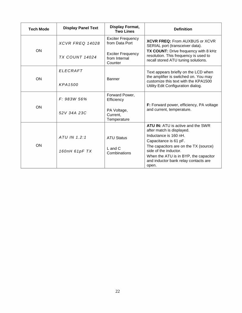
When TECH MODE is enabled (On), additional status text becomes available and can be viewed by tapping the
or keys.
When TECH MODE is disabled (Off) two main screens plus transitory screens (text that displays for a second
or so after something happens) become visible.
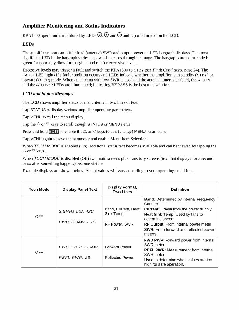
Example displays are shown below. Actual values will vary according to your operating conditions.
Tech Mode Display Panel Text Display Format,
Two Lines Definition
OFF
3.5MHz 50A 42C
PWR 1234W 1.7:1
Band, Current, Heat Sink Temp
RF Power, SWR
Band: Determined by internal Frequency Counter
Current: Drawn from the power supply
Heat Sink Temp: Used by fans to determine speed.
RF Output: From internal power meter
SWR: From forward and reflected power meters
OFF
FWD PWR: 1234W
REFL PWR: 23
Forward Power
Reflected Power
FWD PWR: Forward power from internal SWR meter
REFL PWR: Measurement from internal SWR meter
Used to determine when values are too high for safe operation.
22
Tech Mode Display Panel Text Display Format, Two Lines
Definition
ON
XCVR FREQ 14028
TX COUNT 14024
Exciter Frequency from Data Port
Exciter Frequency from Internal Counter
XCVR FREQ: From AUXBUS or XCVR SERIAL port (transceiver data).
TX COUNT: Drive frequency with 8 kHz resolution. This frequency is used to recall stored ATU tuning solutions.
ON
ELECRAFT
KPA1500
Banner
Text appears briefly on the LCD when the amplifier is switched on. You may customize this text with the KPA1500 Utility Edit Configuration dialog.
ON
F: 983W 56%
52V 34A 23C
Forward Power, Efficiency
PA Voltage, Current, Temperature
F: Forward power, efficiency, PA voltage and current, temperature.
ON
ATU IN 1.2:1
160nH 61pF TX
ATU Status
L and C Combinations
ATU IN: ATU is active and the SWR after match is displayed.
Inductance is 160 nH.
Capacitance is 61 pF.
The capacitors are on the TX (source) side of the inductor.
When the ATU is in BYP, the capacitor and inductor bank relay contacts are open.
23
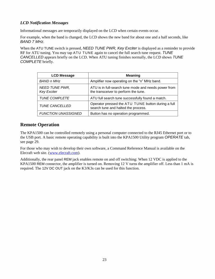
LCD Notification Messages
Informational messages are temporarily displayed on the LCD when certain events occur.
For example, when the band is changed, the LCD shows the new band for about one and a half seconds, like
BAND 7 MHz.
When the ATU TUNE switch is pressed, NEED TUNE PWR, Key Exciter is displayed as a reminder to provide
RF for ATU tuning. You may tap ATU TUNE again to cancel the full search tune request. TUNE
CANCELLED appears briefly on the LCD. When ATU tuning finishes normally, the LCD shows TUNE COMPLETE briefly.
LCD Message Meaning
BAND n MHz Amplifier now operating on the “n” MHz band.
NEED TUNE PWR, Key Exciter
ATU is in full-search tune mode and needs power from the transceiver to perform the tune.
TUNE COMPLETE ATU full search tune successfully found a match.
TUNE CANCELLED Operator pressed the ATU TUNE button during a full search tune and halted the process.
FUNCTION UNASSIGNED Button has no operation programmed.
Remote Operation
The KPA1500 can be controlled remotely using a personal computer connected to the RJ45 Ethernet port or to
the USB port. A basic remote operating capability is built into the KPA1500 Utility program OPERATE tab,
see page 29.
For those who may wish to develop their own software, a Command Reference Manual is available on the
Elecraft web site. (www.elecraft.com).
Additionally, the rear panel REM jack enables remote on and off switching: When 12 VDC is applied to the
KPA1500 REM connector, the amplifier is turned on. Removing 12 V turns the amplifier off. Less than 1 mA is
required. The 12V DC OUT jack on the K3/K3s can be used for this function.
24
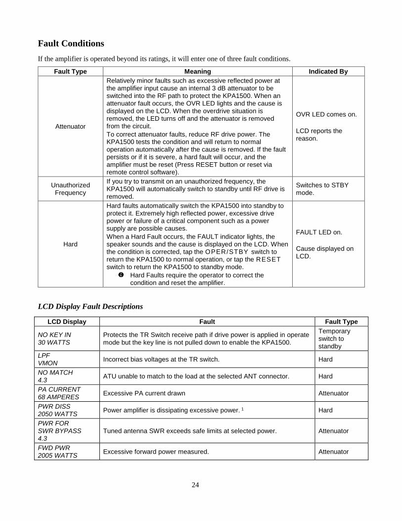
Fault Conditions
If the amplifier is operated beyond its ratings, it will enter one of three fault conditions.
Fault Type Meaning Indicated By
Attenuator
Relatively minor faults such as excessive reflected power at the amplifier input cause an internal 3 dB attenuator to be switched into the RF path to protect the KPA1500. When an attenuator fault occurs, the OVR LED lights and the cause is displayed on the LCD. When the overdrive situation is removed, the LED turns off and the attenuator is removed from the circuit.
To correct attenuator faults, reduce RF drive power. The KPA1500 tests the condition and will return to normal operation automatically after the cause is removed. If the fault persists or if it is severe, a hard fault will occur, and the amplifier must be reset (Press RESET button or reset via remote control software).
OVR LED comes on.
LCD reports the reason.
Unauthorized Frequency
If you try to transmit on an unauthorized frequency, the KPA1500 will automatically switch to standby until RF drive is removed.
Switches to STBY mode.
Hard
Hard faults automatically switch the KPA1500 into standby to protect it. Extremely high reflected power, excessive drive power or failure of a critical component such as a power supply are possible causes.
When a Hard Fault occurs, the FAULT indicator lights, the speaker sounds and the cause is displayed on the LCD. When the condition is corrected, tap the OPER/STBY switch to return the KPA1500 to normal operation, or tap the RESET switch to return the KPA1500 to standby mode.
Hard Faults require the operator to correct the condition and reset the amplifier.
FAULT LED on.
Cause displayed on LCD.
LCD Display Fault Descriptions
LCD Display Fault Fault Type
NO KEY IN 30 WATTS
Protects the TR Switch receive path if drive power is applied in operate mode but the key line is not pulled down to enable the KPA1500.
Temporary switch to standby
LPF VMON
Incorrect bias voltages at the TR switch. Hard
NO MATCH 4.3
ATU unable to match to the load at the selected ANT connector. Hard
PA CURRENT 68 AMPERES
Excessive PA current drawn Attenuator
PWR DISS 2050 WATTS
Power amplifier is dissipating excessive power. 1 Hard
PWR FOR SWR BYPASS 4.3
Tuned antenna SWR exceeds safe limits at selected power. Attenuator
FWD PWR 2005 WATTS
Excessive forward power measured. Attenuator
25
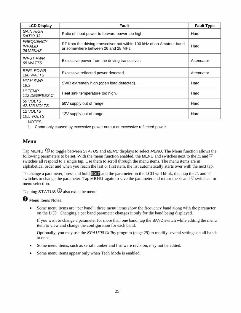
LCD Display Fault Fault Type
GAIN HIGH RATIO 33
Ratio of input power to forward power too high. Hard
FREQUENCY INVALID 26123KHZ
RF from the driving transceiver not within 100 kHz of an Amateur band or somewhere between 26 and 28 MHz
Hard
INPUT PWR 65 WATTS
Excessive power from the driving transceiver. Attenuator
REFL POWR 180 WATTS
Excessive reflected power detected. Attenuator
HIGH SWR 19.3
SWR extremely high (open load detected). Hard
HI TEMP 112 DEGREES C
Heat sink temperature too high. Hard
50 VOLTS 42.123 VOLTS
50V supply out of range. Hard
12 VOLTS
10.5 VOLTS 12V supply out of range Hard
NOTES:
1. Commonly caused by excessive power output or excessive reflected power.
Menu
Tap MENU to toggle between STATUS and MENU displays to select MENU. The Menu function allows the
following parameters to be set. With the menu function enabled, the MENU and switches next to the and
switches all respond to a single tap. Use them to scroll through the menu items. The menu items are in
alphabetical order and when you reach the last or first item, the list automatically starts over with the next tap.
To change a parameter, press and hold EDIT and the parameter on the LCD will blink, then tap the and
switches to change the parameter. Tap MENU again to save the parameter and return the and switches for
menu selection.
Tapping STATUS also exits the menu.
Menu Items Notes:
• Some menu items are “per band”; these menu items show the frequency band along with the parameter
on the LCD. Changing a per band parameter changes it only for the band being displayed.
If you wish to change a parameter for more than one band, tap the BAND switch while editing the menu
item to view and change the configuration for each band.
Optionally, you may use the KPA1500 Utility program (page 29) to modify several settings on all bands
at once.
• Some menu items, such as serial number and firmware revision, may not be edited.
• Some menu items appear only when Tech Mode is enabled.
26
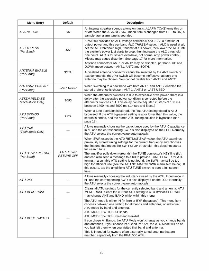
Menu Entry Default Description
ALARM TONE ON An internal speaker sounds a tone on faults. ALARM TONE turns this on or off. When the ALARM TONE menu item is changed from OFF to ON, a sample fault alarm tone is sounded.
ALC THRESH (Per Band)
127
KPA1500 provides an ALC voltage between 0 and -12V, a function of output power and this per-band ALC THRESH value. If ALC is used at all, set the ALC threshold high, transmit at full power, then lower the ALC until the exciter’s power just starts to drop, then increase the ALC threshold one count. ALC is for severe overdrive, not normal amp power control. Misuse may cause distortion. See page 17 for more information.
ANTENNA ENABLE (Per Band)
BOTH
Antenna connectors ANT1 or ANT2 may be disabled, per band. UP and DOWN move between ANT1, ANT2 and BOTH.
A disabled antenna connector cannot be selected by the ANT switch or text commands; the ANT switch will become ineffective, as only one antenna may be chosen. You cannot disable both ANT1 and ANT2.
ANTENNA PREFER
(Per Band) LAST USED
When switching to a new band with both ANT 1 and ANT 2 enabled the stored preference is chosen: ANT 1, ANT 2 or LAST USED.
ATTEN RELEASE (Tech Mode Only)
3000
When the attenuator switches in due to excessive drive power, there is a delay after the excessive power condition is corrected before the attenuator switches out. This delay can be adjusted in steps of 100 ms between 1400 ms and 5000 ms (1.4 sec and 5 sec.)
ATU BYPASS (Per Band)
1.2:1
When a tune operation is started, the first ATU setting tested is ATU bypassed. If the ATU bypassed setting is at or lower than this value, the search is ended, and the stored ATU tuning solution is bypassed (see page 18).
ATU CAP (Tech Mode Only)
— Allows manually choosing the capacitance used by the ATU. Capacitance in pF and the corresponding SWR is also displayed on the LCD. Normally, the ATU selects the correct value automatically.
ATU HiSWR RETUNE (Per-Band)
ATU HiSWR RETUNE OFF
When SWR exceeds the ATU RETUNE SWR value, the ATU examines previously stored tuning settings for the current frequency and chooses the first one that meets the SWR STOP threshold. This does not start a full search tune.
The amplifier pulls down (grounds) the TUNE connector’s KEY line (tip), and can also send a message to a K3 to provide TUNE POWER for ATU tuning. If a suitable ATU setting is not found, the SWR may still be too high for efficient use (see the ATU NO MATCH SWR menu item below). If this occurs, tap the amplifier’s ATU TUNE switch to start a full-search tune.
ATU IND — Allows manually choosing the inductance used by the ATU. Inductance in nH and the corresponding SWR is also displayed on the LCD. Normally, the ATU selects the correct value automatically.
ATU MEM ERASE — Clears all ATU settings for the currently selected band and antenna. ATU MEM ERASE clears the current ATU setting to ATU BYPASSED. You may change ANT and BAND while within this menu.
ATU MODE SWITCH —
The ATU mode is either IN (in line) or BYP (bypassed). This menu item chooses between one setting for all bands and antennas, or individual ATU mode by band and antenna.
ATU MODE SWITCH All Bands
ATU MODE SWITCH Per-Band Per-Ant
If you chose All Bands, the ATU Mode won’t change as you change bands and antennas. If you choose Per-Band Per-Ant, the ATU Mode will be as you last left them when you visited that band and antenna.
This is intended for owners of an externally-tuned antenna that are matched separately from the KPA1500 ATU.
27
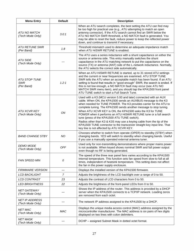
Menu Entry Default Description
ATU NO MATCH (Tech Mode Only)
3.0:1
When an ATU search completes, the best setting the ATU can find may be too high for practical use (e.g., ATU attempting to match an open antenna connector). If the ATU search cannot find an SWR below the ATU NO MATCH SWR threshold, a NO MATCH fault is generated. You may be able to reset the fault, reduce power to keep the reflected power down, and continue to transmit if necessary.
ATU RETUNE SWR (Per Band)
1.8 Threshold mismatch used to determine an adequate impedance match when ATU HiSWR RETUNE is enabled.
ATU SIDE (Tech Mode Only)
—
The ATU uses a series inductance with a shunt capacitance on either the source or antenna side. This entry manually switches the shunt capacitance in the ATU matching network to put the capacitance on the source (TX) or antenna (ANT) side of the L-network inductance. Normally, the ATU selects the correct side automatically.
ATU STOP TUNE SWR (Per Band)
1.2:1
When an ATU HiSWR RETUNE is started, up to 31 stored ATU settings and the current or near frequencies are examined. ATU STOP TUNE SWR tells the ATU when an acceptable match has been found. If an ATU setting is found that results in “good enough” SWR, the search is ended. If this is not low enough, a NO MATCH fault may occur (see ATU NO MATCH SWR menu item), and you should tap the KPA1500 front panel ATU TUNE switch to start a Full Search Tune.
ATU XCVR KEY (Tech Mode Only)
ON
Used with a K3 (MCU version 5.93 and later) connected with an AUX cable. When ON, the KPA1500 sends an AUXBUS message to the K3 when needed for TUNE POWER. The K3 provides carrier for the ATU to complete tuning. The KPA1500 sends another message to stop tuning.
When ATU XCVR KEY is ON, the KPA1500 asks the K3 for TUNE POWER when it performs an ATU HiSWR RETUNE tune or a full search tune (press of the KPA1500 ATU TUNE switch).
Radios other than K3 & K3S may use a keying cable from the tip of the KPA1500 TUNE connector to the transceiver straight key input line. That key line is not affected by ATU XCVR KEY.
BAND CHANGE STBY NO Chooses whether to switch from operate (OPER) to standby (STBY) when changing bands. YES will switch to standby when changing bands. Useful if you use a manually operated external antenna tuner.
DEMO MODE (Tech Mode Only)
OFF Used only for non-transmitting demonstrations where proper mains power is not available. When keyed shows nominal SWR and full power output even though no RF is being generated.
FAN SPEED MIN 0
The speed of the three rear panel fans varies according to the KPA1500 internal temperature. This function sets fan speed from slow to full at all times, independent of heatsink temperature. This setting does not affect the fan in the power supply enclosure.
FIRMWARE VERSION — Displays the installed version of the KPA1500 firmware.
LCD BACKLIGHT 7 Adjusts the brightness of the LCD backlight over a range of 0 to 50.
LCD CONTRAST 23 Adjusts the contrast of LCD characters from 0 to 50.
LED BRIGHTNESS 22 Adjusts the brightness of the front-panel LEDs from 0 to 50.
NET GATEWAY (Tech Mode Only)
— Shows the IP address of the router. This address is provided by a DHCP server when the KPA1500 connects to a TCP/IP network. Leading zeros are removed from each octet.
NET IP ADDRESS (Tech Mode Only)
— The network IP address assigned to the KPA1500 by a DHCP.
NET MAC (Tech Mode Only)
MAC Displays the unique media access control (MAC) address assigned by the microcontroller manufacturer. The MAC address is six pairs of hex digits displayed on two lines with colon delimiters.
NET MASK (Tech Mode Only)
— DCHP – assigned Subnet Mask in dotted octet format.
28
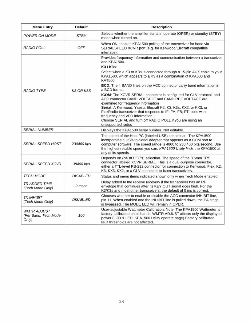
Menu Entry Default Description
POWER ON MODE STBY Selects whether the amplifier starts in operate (OPER) or standby (STBY) mode when turned on.
RADIO POLL OFF When ON enables KPA1500 polling of the transceiver for band via SERIALSPEED XCVR port (e.g. for Kenwood/Elecraft compatible interface).
RADIO TYPE K3 OR K3S
Provides frequency information and communication between a transceiver and KPA1500.
K3 / K3S:
Select when a K3 or K3S is connected through a 15-pin AUX cable to your KPA1500, which appears to a K3 as a combination of KPA500 and KAT500.
BCD: The 4 BAND lines on the ACC connector carry band information in a BCD format.
ICOM: The XCVR SERIAL connector is configured for CI-V protocol, and ACC connector BAND VOLTAGE and BAND REF VOLTAGE are examined for frequency information Serial: A Kenwood, Yaesu, Elecraft K2, K3, K3S, KX2, or KX3, or FlexRadio transceiver that responds to IF; FA; FB; FT; polls with frequency and VFO information. Choose SERIAL and turn off RADIO POLL if you are using an unsupported radio.
SERIAL NUMBER — Displays the KPA1500 serial number. Not editable.
SERIAL SPEED HOST 230400 bps
The speed of the Host PC (labeled USB) connection. The KPA1500 incorporates a USB-to-Serial adapter that appears as a COM port to computer software. The speed range is 4800 to 230,400 bits/second. Use the highest reliable speed you can. KPA1500 Utility finds the KPA1500 at any of its speeds.
SERIAL SPEED XCVR 38400 bps
Depends on RADIO TYPE selection. The speed of the 3.5mm TRS connector labeled XCVR SERIAL. This is a dual-purpose connector, either a TTL-level RS-232 connector for connection to Kenwood, Flex, K2, K3, KX3, KX2, or a CI-V connector to Icom transceivers.
TECH MODE DISABLED Status and menu items indicated shown only when Tech Mode enabled.
TR ADDED TIME (Tech Mode Only)
0 msec Delay added to the receive recovery if the transceiver has an RF envelope that continues after its KEY OUT signal goes high. For the K3/K3S and most other transceivers, the default of 0 ms is correct.
TX INHIBIT (Tech Mode Only)
DISABLED Chooses whether to enable or disable the ACC connector INHIBIT line, pin 11. When enabled and the INHIBIT line is pulled down, the PA stage is bypassed. The MODE LED will remain in OPER.
WMTR ADJUST (Per Band, Tech Mode Only)
100
User-adjustable Wattmeter Calibration. Note: The KPA1500 Wattmeter is factory-calibrated on all bands. WMTR ADJUST affects only the displayed power (LCD & LED, KPA1500 Utility operate page).Factory calibrated fault thresholds are not affected.
29
KPA1500 Utility Program
The KPA1500 Utility program is available for downloading free from Elecraft at www.elecraft.com. It is
essential for updating your KPA1500 firmware and may be used to more quickly edit various parameter settings.
1. Download the KPA1500 Utility program and install it on your computer.
2. Connect the USB A to B interface cable supplied with your KPA1500 between the USB port on the
KPA1500 rear panel and your personal computer.
The KPA1500 must be connected directly to the USB port on your computer.
KPA1500 Firmware Updates
From time to time updated and improved firmware may become available for the KPA1500 and can be
downloaded from www.elecraft.com and installed using the KPA1500 Utility Program.
To download the firmware:
1. Connect your personal computer to the KPA1500 via the USB port and launch the KPA1500 Utility
Program.
2. Click on Firmware tab and then click on Copy Firmware Files from Elecraft to download the latest
production released firmware.
3. Beta firmware is made available prior to it going into full production at Elecraft. Follow the instructions
on the KPA1500 Firmware page if you would like to try it.
To install new firmware in your KPA1500:
1. Click on the KPA1500 Utility Program Send Firmware to the KPA1500 switch to start the transfer.
Follow the on-screen instructions.
2. During download the LCD will display FIRMWARE LOAD. The KPA1500 will return to its normal
power on state when the transfer is completed.
Be sure to check the notes supplied with the new firmware. They may include changes that affect the
instructions in this manual.
Checking your Firmware Version
Use the Menu entry FIRMWARE VERSION to determine the currently-installed firmware (see page 25). This
is also shown on the KPA1500 Utility Firmware tab as the “installed” version.
Forcing a Firmware Load
If the KPA1500 becomes unresponsive, you may force a re-load of its operating firmware. Connect a computer
running the KPA1500 as described above. Press and hold the front-panel AUX key for more than 10 seconds and
the hardware bootloader will run. Click on the Utility Test Connection and then Send Firmware to the KPA1500 switch to start the transfer.
30
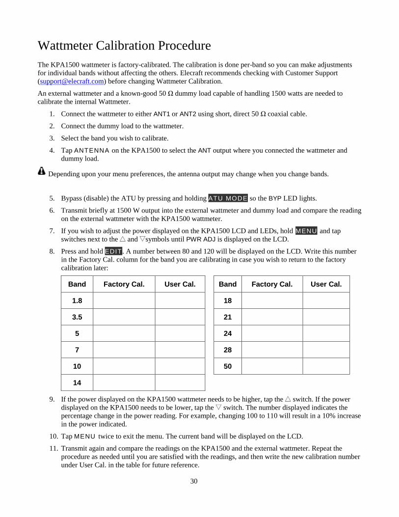
Wattmeter Calibration Procedure
The KPA1500 wattmeter is factory-calibrated. The calibration is done per-band so you can make adjustments
for individual bands without affecting the others. Elecraft recommends checking with Customer Support
([email protected]) before changing Wattmeter Calibration.
An external wattmeter and a known-good 50 Ω dummy load capable of handling 1500 watts are needed to
calibrate the internal Wattmeter.
1. Connect the wattmeter to either ANT1 or ANT2 using short, direct 50 Ω coaxial cable.
2. Connect the dummy load to the wattmeter.
3. Select the band you wish to calibrate.
4. Tap ANTENNA on the KPA1500 to select the ANT output where you connected the wattmeter and
dummy load.
Depending upon your menu preferences, the antenna output may change when you change bands.
5. Bypass (disable) the ATU by pressing and holding ATU MODE so the BYP LED lights.
6. Transmit briefly at 1500 W output into the external wattmeter and dummy load and compare the reading
on the external wattmeter with the KPA1500 wattmeter.
7. If you wish to adjust the power displayed on the KPA1500 LCD and LEDs, hold MENU and tap
switches next to the and symbols until PWR ADJ is displayed on the LCD.
8. Press and hold EDIT . A number between 80 and 120 will be displayed on the LCD. Write this number
in the Factory Cal. column for the band you are calibrating in case you wish to return to the factory
calibration later:
Band Factory Cal. User Cal. Band Factory Cal. User Cal.
1.8 18
3.5 21
5 24
7 28
10 50
14
9. If the power displayed on the KPA1500 wattmeter needs to be higher, tap the switch. If the power
displayed on the KPA1500 needs to be lower, tap the switch. The number displayed indicates the
percentage change in the power reading. For example, changing 100 to 110 will result in a 10% increase
in the power indicated.
10. Tap MENU twice to exit the menu. The current band will be displayed on the LCD.
11. Transmit again and compare the readings on the KPA1500 and the external wattmeter. Repeat the
procedure as needed until you are satisfied with the readings, and then write the new calibration number
under User Cal. in the table for future reference.
31
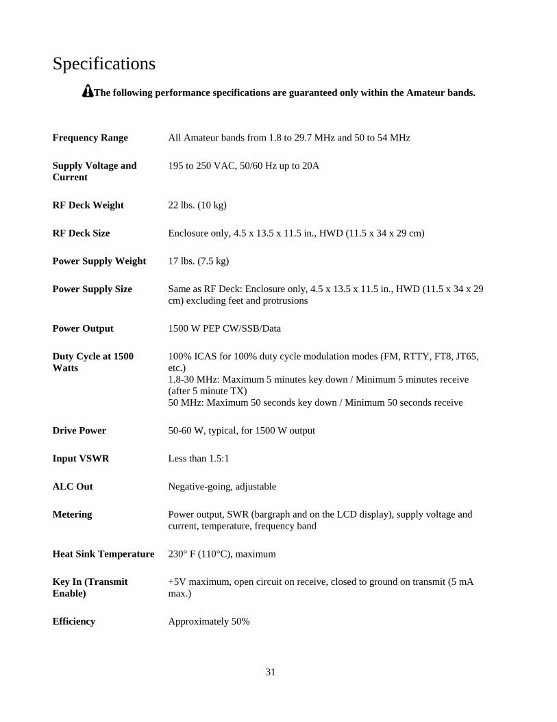
Specifications
The following performance specifications are guaranteed only within the Amateur bands.
Frequency Range All Amateur bands from 1.8 to 29.7 MHz and 50 to 54 MHz
Supply Voltage and
Current
195 to 250 VAC, 50/60 Hz up to 20A
RF Deck Weight 22 lbs. (10 kg)
RF Deck Size Enclosure only, 4.5 x 13.5 x 11.5 in., HWD (11.5 x 34 x 29 cm)
Power Supply Weight 17 lbs. (7.5 kg)
Power Supply Size Same as RF Deck: Enclosure only, 4.5 x 13.5 x 11.5 in., HWD (11.5 x 34 x 29
cm) excluding feet and protrusions
Power Output 1500 W PEP CW/SSB/Data
Duty Cycle at 1500
Watts
100% ICAS for 100% duty cycle modulation modes (FM, RTTY, FT8, JT65,
etc.)
1.8-30 MHz: Maximum 5 minutes key down / Minimum 5 minutes receive
(after 5 minute TX)
50 MHz: Maximum 50 seconds key down / Minimum 50 seconds receive
Drive Power 50-60 W, typical, for 1500 W output
Input VSWR Less than 1.5:1
ALC Out Negative-going, adjustable
Metering Power output, SWR (bargraph and on the LCD display), supply voltage and
current, temperature, frequency band
Heat Sink Temperature 230° F (110°C), maximum
Key In (Transmit
Enable)
+5V maximum, open circuit on receive, closed to ground on transmit (5 mA
max.)
Efficiency Approximately 50%
32
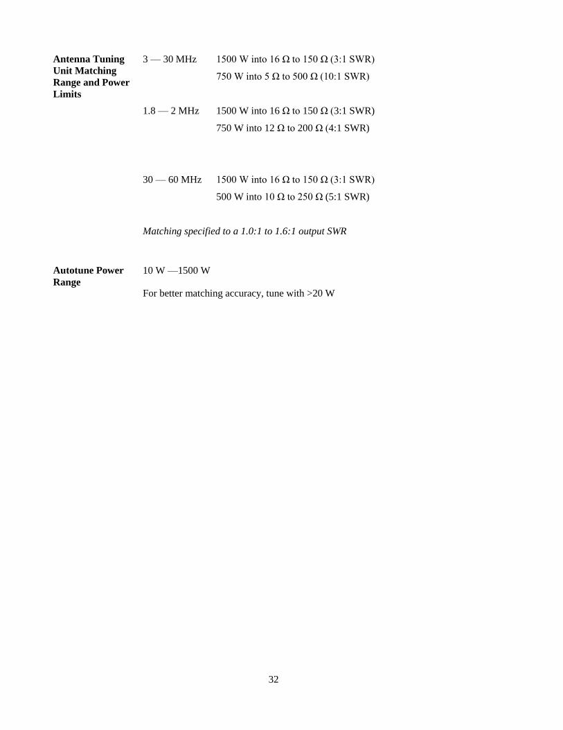
Antenna Tuning
Unit Matching
Range and Power
Limits
3 — 30 MHz
1.8 — 2 MHz
30 — 60 MHz
1500 W into 16 Ω to 150 Ω (3:1 SWR)
750 W into 5 Ω to 500 Ω (10:1 SWR)
1500 W into 16 Ω to 150 Ω (3:1 SWR)
750 W into 12 Ω to 200 Ω (4:1 SWR)
1500 W into 16 Ω to 150 Ω (3:1 SWR)
500 W into 10 Ω to 250 Ω (5:1 SWR)
Matching specified to a 1.0:1 to 1.6:1 output SWR
Autotune Power
Range
10 W —1500 W
For better matching accuracy, tune with >20 W

33
Customer Service and Support
Technical Assistance
You can send e-mail to [email protected] and we will respond quickly – typically the same day Monday
through Friday. If you need replacement parts, send an e-mail to [email protected]. Telephone assistance is
available from 9 A.M. to 5 P.M. Pacific time (weekdays only) at 831-763-4211. Please use e-mail rather than
calling when possible since this gives us a written record of the details of your problem and allows us to handle
a larger number of requests each day.
Repair / Alignment Service
If necessary, you may return your Elecraft product to us for repair or alignment. (Note: We offer e-mail and
phone support, so please try that route first as we can usually help you find the problem quickly.)
IMPORTANT: You must contact Elecraft Customer Support before mailing your product to obtain
authorization for the return, what address to ship it to and current information on repair fees and turnaround
times. (Frequently we can determine the cause of your problem and save you the trouble of shipping it back to
us.) Our repair location may be different from our factory location. We will give you the address to ship your
product at the time of repair authorization. Packages shipped without authorization will incur an additional
shipping charge for reshipment to our repair depot.
Elecraft 1-Year Limited Warranty
This warranty is effective as of the date of first consumer purchase (or if shipped from the factory, the date the
product is shipped to the customer). It covers both our kits and fully assembled products. For kits, before requesting
warranty service, you should fully complete the assembly, carefully following all instructions in the manual.
Who is covered: This warranty covers the original owner of the Elecraft product as disclosed to Elecraft at the time
of order. Elecraft products transferred by the purchaser to a third party, either by sale, gift, or other method, who is
not disclosed to Elecraft at the time of original order, are not covered by this warranty. If the Elecraft product is being
bought indirectly for a third party, the third party’s name and address must be provided at time of order to ensure
warranty coverage.
What is covered: During the first year after date of purchase, Elecraft will replace defective or missing parts free of
charge (post-paid). We will also correct any malfunction to kits or assembled units caused by defective parts and
materials. Purchaser pays inbound shipping to us for warranty repair; we pay shipping to return the repaired
equipment to you by UPS ground service or equivalent to the continental USA and Canada. For Alaska, Hawaii, and
other destinations outside the U.S. and Canada, actual return shipping cost is paid by the owner.
What is not covered: This warranty does not cover correction of kit assembly errors. It also does not cover
misalignment; repair of damage caused by misuse, negligence, or builder modifications; or any performance
malfunctions involving non-Elecraft accessory equipment. The use of acid-core solder, water-soluble flux solder, or
any corrosive or conductive flux or solvent will void this warranty in its entirety. Also not covered is reimbursement
for loss of use, inconvenience, customer assembly or alignment time, or cost of unauthorized service.
Limitation of incidental or consequential damages: This warranty does not extend to non-Elecraft equipment or
components used in conjunction with our products. Any such repair or replacement is the customer. Elecraft will not
be liable for any special indirect, incidental or consequential damages, including but not limited to any loss of
business or profits.
34
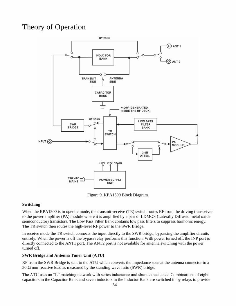
Theory of Operation
Figure 9. KPA1500 Block Diagram.
Switching
When the KPA1500 is in operate mode, the transmit-receive (TR) switch routes RF from the driving transceiver
to the power amplifier (PA) module where it is amplified by a pair of LDMOS (Laterally Diffused metal oxide
semiconductor) transistors. The Low Pass Filter Bank contains low pass filters to suppress harmonic energy.
The TR switch then routes the high-level RF power to the SWR Bridge.
In receive mode the TR switch connects the input directly to the SWR bridge, bypassing the amplifier circuits
entirely. When the power is off the bypass relay performs this function. With power turned off, the INP port is
directly connected to the ANT1 port. The ANT2 port is not available for antenna switching with the power
turned off.
SWR Bridge and Antenna Tuner Unit (ATU)
RF from the SWR Bridge is sent to the ATU which converts the impedance seen at the antenna connector to a
50 Ω non-reactive load as measured by the standing wave ratio (SWR) bridge.
The ATU uses an “L” matching network with series inductance and shunt capacitance. Combinations of eight
capacitors in the Capacitor Bank and seven inductors in the Inductor Bank are switched in by relays to provide
35
up to 2624 pF of capacitance and up to 8370 nH of inductance. An algorithm operates relays to select the
inductors and capacitors required and chooses whether the capacitors are placed on the transmit side or antenna
side of the inductors to arrive at a tuning solution for the current operating frequency. This is called a Full Cycle
Tune.
When the ATU relays are changing capacitors or inductors, the amplifier circuit is kept in receive mode (RF
routed through the TR switch but not the PA module), using only the RF power from the driving transceiver to
monitor the SWR.
Control Logic and Fault Conditions
A microcontroller unit (MCU) controls and monitors critical operating conditions. The MCU also controls the
ATU functions.
During normal operation, the MCU performs the following functions:
• When a key line low is sensed, the amplifier is switched into transmit mode if no fault conditions are
present, the input signal is not in the 26 to 28 MHz range and an ATU tune operation is not underway.
• When RF drive is applied, the frequency is measured and the correct low pass filter is switched into the
signal path.
• The KPA1500 exchanges band data with the Elecraft K3 or K3S and automatically selects the proper
low pass filter, enabling rapid band changes. The MCU does not need to detect the frequency input for
filter selection.
However, RF frequency sensing does take priority if a tuning solution does not agree with the band data
to avoid transmitting into an incorrect filter. The optional KPAK3AUX cable kit is needed to enable this
feature, as shown in Figure 5, page 12 or Figure 6, page 13.
Under fault conditions, the MCU protects the amplifier to prevent damage or improper operation. There are
three levels of fault conditions (Attenuator, Unauthorized Frequency and Hard), and are triggered by the
following conditions:
• A 3 dB attenuator is automatically switched in if excessive the RF drive power is applied or if other
conditions occur such as excessive RF output, reflected power (high SWR) or current is drawn by the
finals.
• If an unauthorized frequency is transmitted, the KPA1500 switches to standby until RF drive is
removed. This fault will automatically reset if a valid frequency is applied.
• When a fault condition is detected, the TR switch is inhibited so no RF power reaches the PA module. If
RF drive is high enough to possibly damage the TR switch, the amplifier is switched to bypass,
protecting the TR switch.
The amplifier is always switched to STBY during hard faults. A hard fault requires operator action to reset the
amplifier.
Tuning Solutions Memory
To facilitate very rapid frequency changes, tuning solutions are stored in memory and recalled when returning to
that frequency. Settings are recalled almost instantly when returning to that frequency later.
The entire spectrum from 1.8 through 60 MHz is divided into frequency segments and tuning information is
stored for each segment in which you have successfully completed a tune operation. Memory is allocated for 31
tune solutions per frequency segment.
When starting a tune operation for a new frequency segment, the ATU first tries settings in the nearest
frequency segments that do have tuning data for the antenna connector in use. See antenna enable and antenna
prefer menu entries on page 25.
36
The Tuning Segments
Since retuning is normally required over a narrower frequency range on the lower frequencies to maintain a low
SWR, the lower frequencies have narrower segments assigned as follows:
• Below 3 MHz the segments are 10 kHz wide.
• From 3 MHz through 26 MHz the segments are 20 kHz wide.
• From 26 MHz to 38 MHz the segments are 100 kHz wide.
• From 38 MHz to 60 MHz the segments are 200 kHz wide.
The center frequencies for each segment are listed in the Appendix.
Amplifier Cooling
Three fans cool the RF deck heat sink. To minimize noise, the fans remain off until the heat sink reaches 60C.
At that temperature, the center fan begins rotating at its lowest speed. As the temperature increases in steps of
5C, the outer fans start at their lowest speed, then all fans increase together.
The external power supply provides 50 VDC, 12 VDC, and 12 VAC to the amplifier.
37
AUX and XCVR Serial Connector Interfaces
Do not attach a common VGA cable to the AUX connector.
When used with the optional KPAK3AUX cable kit, the AUX connector provides an interface for enhanced
operation between the KPA1500 and a K3 or K3S transceiver.
This section describes how to interface the KPA1500 to non K3 or K3S transceivers, including the K2 and rigs
made by other manufacturers. There are two interfaces on the KPA1500: The AUX port, described above and the
XCVR SERIAL port.
The XCVR Serial port provides RS232 level data for other transceivers such as the Elecraft K2 and some
Kenwood, Yaesu and Icom transceivers.
Below are the signals available at the AUX connector.
Refer to the RADIO entry in the menu (page 25) to enable communications via the AUX connector.
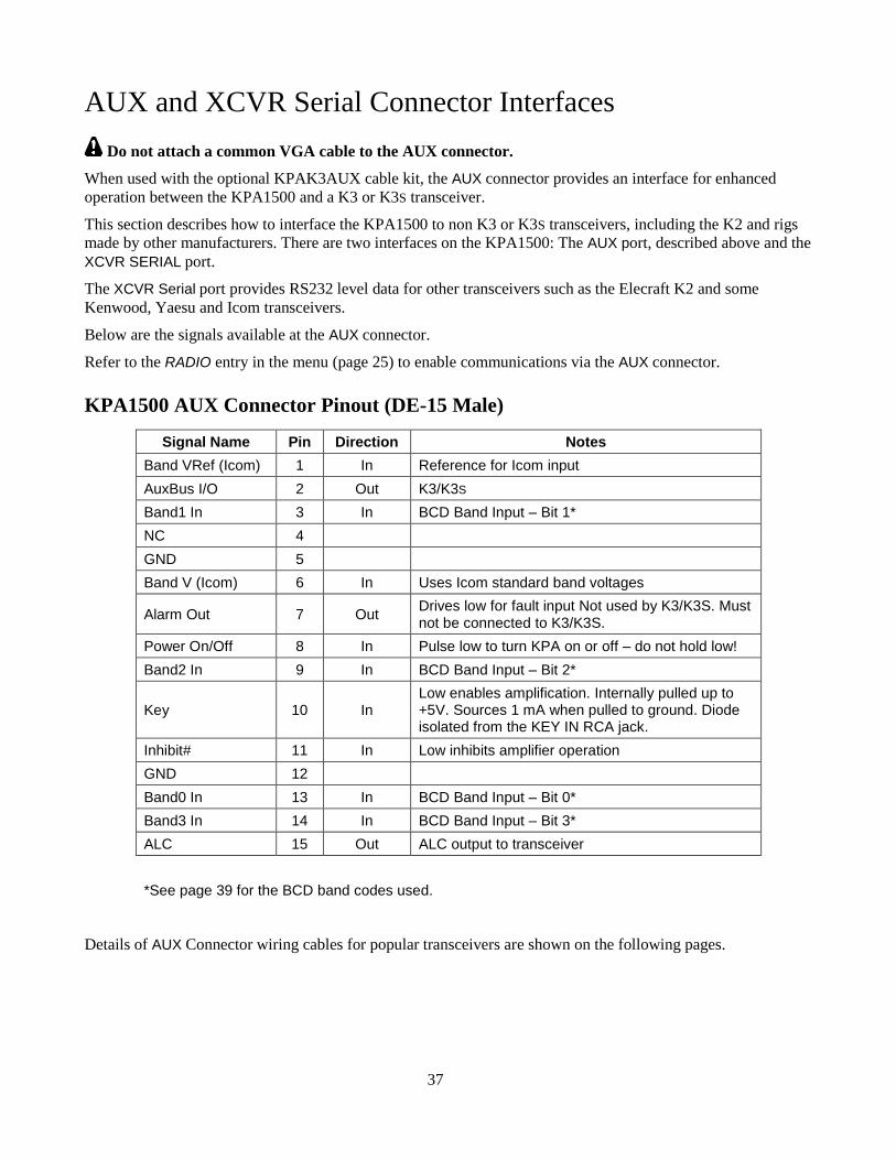
KPA1500 AUX Connector Pinout (DE-15 Male)
Signal Name Pin Direction Notes
Band VRef (Icom) 1 In Reference for Icom input
AuxBus I/O 2 Out K3/K3S
Band1 In 3 In BCD Band Input – Bit 1*
NC 4
GND 5
Band V (Icom) 6 In Uses Icom standard band voltages
Alarm Out 7 Out Drives low for fault input Not used by K3/K3S. Must not be connected to K3/K3S.
Power On/Off 8 In Pulse low to turn KPA on or off – do not hold low!
Band2 In 9 In BCD Band Input – Bit 2*
Key 10 In Low enables amplification. Internally pulled up to +5V. Sources 1 mA when pulled to ground. Diode isolated from the KEY IN RCA jack.
Inhibit# 11 In Low inhibits amplifier operation
GND 12
Band0 In 13 In BCD Band Input – Bit 0*
Band3 In 14 In BCD Band Input – Bit 3*
ALC 15 Out ALC output to transceiver
*See page 39 for the BCD band codes used.
Details of AUX Connector wiring cables for popular transceivers are shown on the following pages.
38
Elecraft KPAK3AUX Interface Cable
This is available direct from the Elecraft Sales department (page 33): Order KPAK3AUX for the complete set:
• KPAK3AUX Cable, 59.5” (1.5 m) long. May be ordered separately. Order E850463.
• 15-pin Y cable that allows access to the K3 or K3S AUX port for other devices. May be ordered
separately. Order E980190.
• 15-pin male-female Key Line Interrupter.
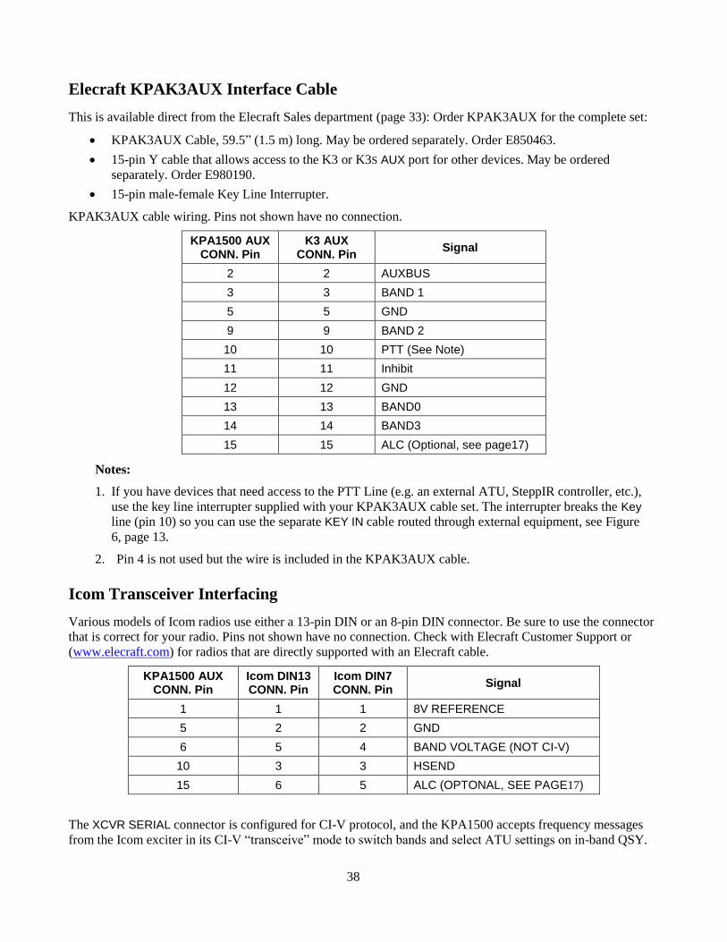
KPAK3AUX cable wiring. Pins not shown have no connection.
KPA1500 AUX CONN. Pin
K3 AUX CONN. Pin
Signal
2 2 AUXBUS
3 3 BAND 1
5 5 GND
9 9 BAND 2
10 10 PTT (See Note)
11 11 Inhibit
12 12 GND
13 13 BAND0
14 14 BAND3
15 15 ALC (Optional, see page17)
Notes:
1. If you have devices that need access to the PTT Line (e.g. an external ATU, SteppIR controller, etc.),
use the key line interrupter supplied with your KPAK3AUX cable set. The interrupter breaks the Key
line (pin 10) so you can use the separate KEY IN cable routed through external equipment, see Figure
6, page 13.
2. Pin 4 is not used but the wire is included in the KPAK3AUX cable.
Icom Transceiver Interfacing
Various models of Icom radios use either a 13-pin DIN or an 8-pin DIN connector. Be sure to use the connector
that is correct for your radio. Pins not shown have no connection. Check with Elecraft Customer Support or
(www.elecraft.com) for radios that are directly supported with an Elecraft cable.
KPA1500 AUX CONN. Pin
Icom DIN13 CONN. Pin
Icom DIN7 CONN. Pin
Signal
1 1 1 8V REFERENCE
5 2 2 GND
6 5 4 BAND VOLTAGE (NOT CI-V)
10 3 3 HSEND
15 6 5 ALC (OPTONAL, SEE PAGE17)
The XCVR SERIAL connector is configured for CI-V protocol, and the KPA1500 accepts frequency messages
from the Icom exciter in its CI-V “transceive” mode to switch bands and select ATU settings on in-band QSY.
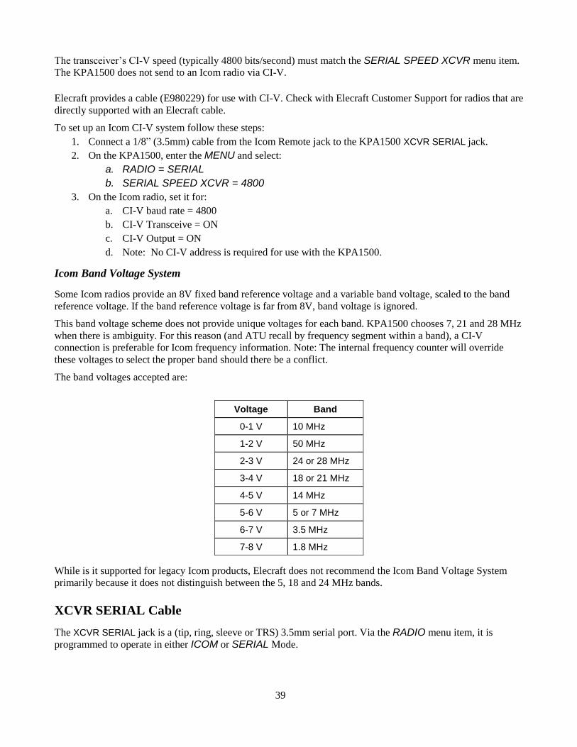
39
The transceiver’s CI-V speed (typically 4800 bits/second) must match the SERIAL SPEED XCVR menu item.
The KPA1500 does not send to an Icom radio via CI-V.
Elecraft provides a cable (E980229) for use with CI-V. Check with Elecraft Customer Support for radios that are
directly supported with an Elecraft cable.
To set up an Icom CI-V system follow these steps:
1. Connect a 1/8” (3.5mm) cable from the Icom Remote jack to the KPA1500 XCVR SERIAL jack.
2. On the KPA1500, enter the MENU and select:
a. RADIO = SERIAL
b. SERIAL SPEED XCVR = 4800
3. On the Icom radio, set it for:
a. CI-V baud rate = 4800
b. CI-V Transceive = ON
c. CI-V Output = ON
d. Note: No CI-V address is required for use with the KPA1500.
Icom Band Voltage System
Some Icom radios provide an 8V fixed band reference voltage and a variable band voltage, scaled to the band
reference voltage. If the band reference voltage is far from 8V, band voltage is ignored.
This band voltage scheme does not provide unique voltages for each band. KPA1500 chooses 7, 21 and 28 MHz
when there is ambiguity. For this reason (and ATU recall by frequency segment within a band), a CI-V
connection is preferable for Icom frequency information. Note: The internal frequency counter will override
these voltages to select the proper band should there be a conflict.
The band voltages accepted are:
While is it supported for legacy Icom products, Elecraft does not recommend the Icom Band Voltage System
primarily because it does not distinguish between the 5, 18 and 24 MHz bands.
XCVR SERIAL Cable
The XCVR SERIAL jack is a (tip, ring, sleeve or TRS) 3.5mm serial port. Via the RADIO menu item, it is
programmed to operate in either ICOM or SERIAL Mode.
Voltage Band
0-1 V 10 MHz
1-2 V 50 MHz
2-3 V 24 or 28 MHz
3-4 V 18 or 21 MHz
4-5 V 14 MHz
5-6 V 5 or 7 MHz
6-7 V 3.5 MHz
7-8 V 1.8 MHz
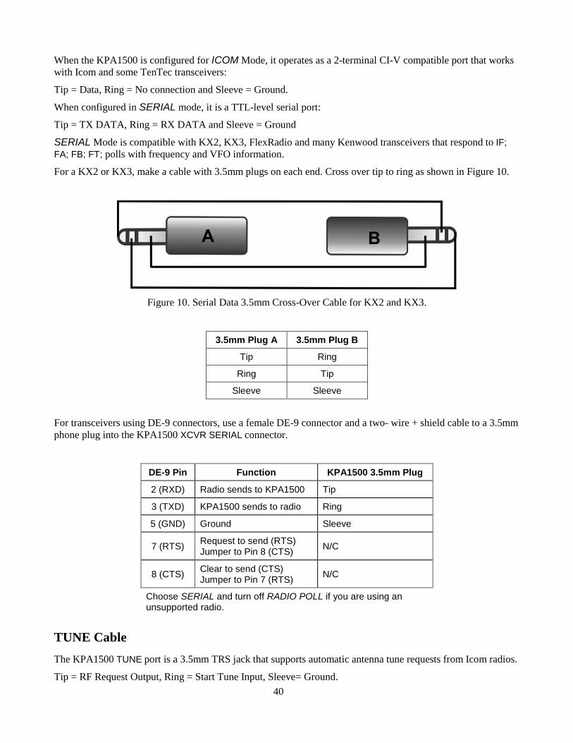
40
When the KPA1500 is configured for ICOM Mode, it operates as a 2-terminal CI-V compatible port that works
with Icom and some TenTec transceivers:
Tip = Data, Ring = No connection and Sleeve = Ground.
When configured in SERIAL mode, it is a TTL-level serial port:
Tip = TX DATA, Ring = RX DATA and Sleeve = Ground
SERIAL Mode is compatible with KX2, KX3, FlexRadio and many Kenwood transceivers that respond to IF;
FA; FB; FT; polls with frequency and VFO information.
For a KX2 or KX3, make a cable with 3.5mm plugs on each end. Cross over tip to ring as shown in Figure 10.
Figure 10. Serial Data 3.5mm Cross-Over Cable for KX2 and KX3.
3.5mm Plug A 3.5mm Plug B
Tip Ring
Ring Tip
Sleeve Sleeve
For transceivers using DE-9 connectors, use a female DE-9 connector and a two- wire + shield cable to a 3.5mm
phone plug into the KPA1500 XCVR SERIAL connector.
DE-9 Pin Function KPA1500 3.5mm Plug
2 (RXD) Radio sends to KPA1500 Tip
3 (TXD) KPA1500 sends to radio Ring
5 (GND) Ground Sleeve
7 (RTS) Request to send (RTS) Jumper to Pin 8 (CTS)
N/C
8 (CTS) Clear to send (CTS) Jumper to Pin 7 (RTS)
N/C
Choose SERIAL and turn off RADIO POLL if you are using an unsupported radio.
TUNE Cable
The KPA1500 TUNE port is a 3.5mm TRS jack that supports automatic antenna tune requests from Icom radios.
Tip = RF Request Output, Ring = Start Tune Input, Sleeve= Ground.
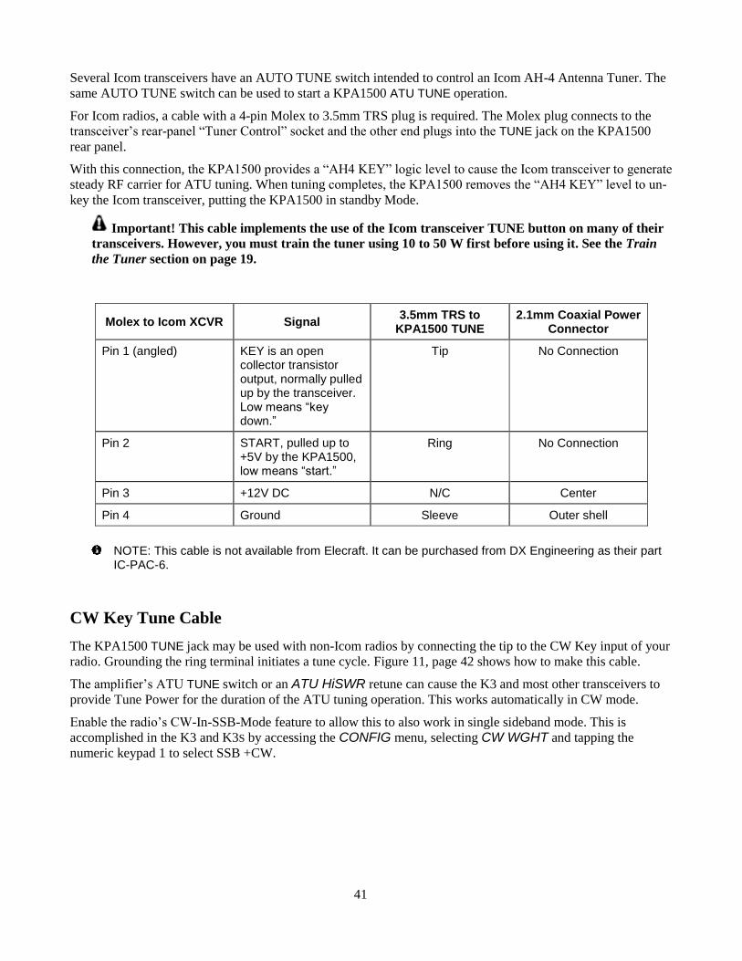
41
Several Icom transceivers have an AUTO TUNE switch intended to control an Icom AH-4 Antenna Tuner. The
same AUTO TUNE switch can be used to start a KPA1500 ATU TUNE operation.
For Icom radios, a cable with a 4-pin Molex to 3.5mm TRS plug is required. The Molex plug connects to the
transceiver’s rear-panel “Tuner Control” socket and the other end plugs into the TUNE jack on the KPA1500
rear panel.
With this connection, the KPA1500 provides a “AH4 KEY” logic level to cause the Icom transceiver to generate
steady RF carrier for ATU tuning. When tuning completes, the KPA1500 removes the “AH4 KEY” level to un-
key the Icom transceiver, putting the KPA1500 in standby Mode.
Important! This cable implements the use of the Icom transceiver TUNE button on many of their
transceivers. However, you must train the tuner using 10 to 50 W first before using it. See the Train
the Tuner section on page 19.
Molex to Icom XCVR Signal 3.5mm TRS to
KPA1500 TUNE 2.1mm Coaxial Power
Connector
Pin 1 (angled) KEY is an open collector transistor output, normally pulled up by the transceiver. Low means “key down.”
Tip No Connection
Pin 2 START, pulled up to +5V by the KPA1500, low means “start.”
Ring No Connection
Pin 3 +12V DC N/C Center
Pin 4 Ground Sleeve Outer shell
NOTE: This cable is not available from Elecraft. It can be purchased from DX Engineering as their part IC-PAC-6.
CW Key Tune Cable
The KPA1500 TUNE jack may be used with non-Icom radios by connecting the tip to the CW Key input of your
radio. Grounding the ring terminal initiates a tune cycle. Figure 11, page 42 shows how to make this cable.
The amplifier’s ATU TUNE switch or an ATU HiSWR retune can cause the K3 and most other transceivers to
provide Tune Power for the duration of the ATU tuning operation. This works automatically in CW mode.
Enable the radio’s CW-In-SSB-Mode feature to allow this to also work in single sideband mode. This is
accomplished in the K3 and K3S by accessing the CONFIG menu, selecting CW WGHT and tapping the
numeric keypad 1 to select SSB +CW.
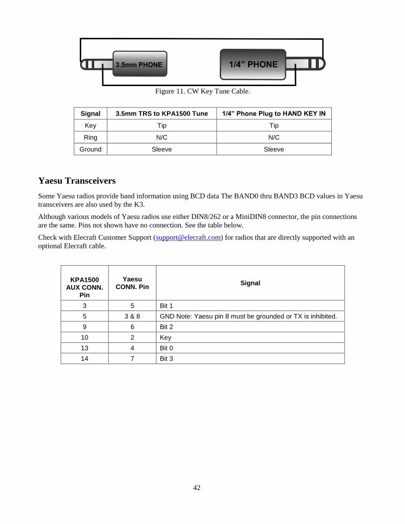
42
Figure 11. CW Key Tune Cable.
Signal 3.5mm TRS to KPA1500 Tune 1/4” Phone Plug to HAND KEY IN
Key Tip Tip
Ring N/C N/C
Ground Sleeve Sleeve
Yaesu Transceivers
Some Yaesu radios provide band information using BCD data The BAND0 thru BAND3 BCD values in Yaesu
transceivers are also used by the K3.
Although various models of Yaesu radios use either DIN8/262 or a MiniDIN8 connector, the pin connections
are the same. Pins not shown have no connection. See the table below.
Check with Elecraft Customer Support ([email protected]) for radios that are directly supported with an
optional Elecraft cable.
KPA1500 AUX CONN.
Pin
Yaesu CONN. Pin
Signal
3 5 Bit 1
5 3 & 8 GND Note: Yaesu pin 8 must be grounded or TX is inhibited.
9 6 Bit 2
10 2 Key
13 4 Bit 0
14 7 Bit 3
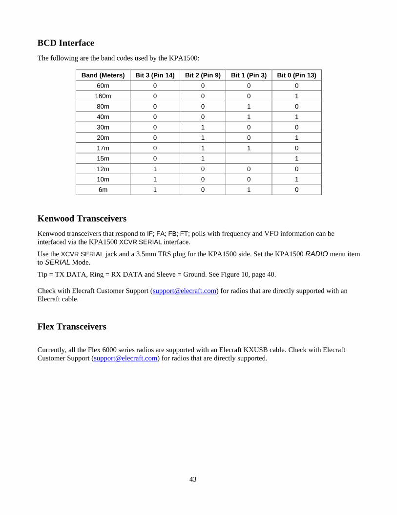
43
BCD Interface
The following are the band codes used by the KPA1500:
Band (Meters) Bit 3 (Pin 14) Bit 2 (Pin 9) Bit 1 (Pin 3) Bit 0 (Pin 13)
60m 0 0 0 0
160m 0 0 0 1
80m 0 0 1 0
40m 0 0 1 1
30m 0 1 0 0
20m 0 1 0 1
17m 0 1 1 0
15m 0 1 1
12m 1 0 0 0
10m 1 0 0 1
6m 1 0 1 0
Kenwood Transceivers
Kenwood transceivers that respond to IF; FA; FB; FT; polls with frequency and VFO information can be
interfaced via the KPA1500 XCVR SERIAL interface.
Use the XCVR SERIAL jack and a 3.5mm TRS plug for the KPA1500 side. Set the KPA1500 RADIO menu item
to SERIAL Mode.
Tip = TX DATA, Ring = RX DATA and Sleeve = Ground. See Figure 10, page 40.
Check with Elecraft Customer Support ([email protected]) for radios that are directly supported with an
Elecraft cable.
Flex Transceivers
Currently, all the Flex 6000 series radios are supported with an Elecraft KXUSB cable. Check with Elecraft
Customer Support ([email protected]) for radios that are directly supported.
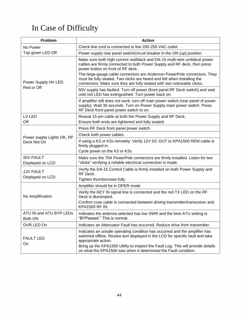
44
In Case of Difficulty
Problem Action
No Power
Top green LED Off
Check line cord is connected to live 200-250 VAC outlet
Power supply rear panel switch/circuit breaker in the ON (up) position
Power Supply HV LED
Red or Off
Make sure both high current red/black and DA-15 multi-wire umbilical power cables are firmly connected to both Power Supply and RF deck, then press power button on front of RF deck.
The large-gauge cable connectors are Anderson PowerPole connectors. They must be fully seated. Two clicks are heard and felt when installing the connectors. Make sure they are fully seated with two noticeable clicks.
50V supply has faulted. Turn off power (front panel RF Deck switch) and wait until red LED has extinguished. Turn power back on.
If amplifier still does not work, turn off main power switch (rear panel of power supply). Wait 30 seconds. Turn on Power Supply main power switch. Press RF Deck front panel power switch to on.
LV LED
Off
Reseat 15-pin cable at both the Power Supply and RF Deck.
Ensure both ends are tightened and fully seated.
Power supply Lights OK, RF Deck Not On
Press RF Deck front panel power switch.
Check both power cables.
If using a K3 or K3S remotely: Verify 12V DC OUT to KPA1500 REM cable is firmly plugged in.
Cycle power on the K3 or K3S.
50V FAULT
Displayed on LCD
Make sure the 75A PowerPole connectors are firmly installed. Listen for two “clicks” verifying a reliable electrical connection is made.
12V FAULT
Displayed on LCD
Verify the DA-15 Control Cable is firmly installed on both Power Supply and RF Deck.
Tighten thumbscrews fully.
No Amplification
Amplifier should be in OPER mode
Verify the KEY IN signal line is connected and the red TX LED on the RF Deck is illuminated.
Confirm coax cable is connected between driving transmitter/transceiver and KPA1500 RF IN.
ATU IN and ATU BYP LEDs
Both ON
Indicates the antenna selected has low SWR and the best ATU setting is “BYPassed.” This is normal.
OVR LED On Indicates an Attenuator Fault has occurred. Reduce drive from transmitter.
FAULT LED
On
Indicates an unsafe operating condition has occurred and the amplifier has switched offline. Review text displayed in the LCD for specific fault and take appropriate action.
Bring up the KPA1500 Utility to inspect the Fault Log. This will provide details on what the KPA1500 saw when it determined the Fault condition.
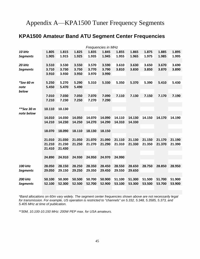
45
Appendix A—KPA1500 Tuner Frequency Segments
KPA1500 Amateur Band ATU Segment Center Frequencies
Frequencies in MHz 10 kHz 1.805 1.815 1.825 1.835 1.845 1.855 1.865 1.875 1.885 1.895 Segments 1.905 1.915 1.925 1.935 1.945 1.955 1.965 1.975 1.985 1.995
20 kHz 3.510 3.530 3.550 3.570 3.590 3.610 3.630 3.650 3.670 3.690 Segments 3.710 3.730 3.750 3.770 3.790 3.810 3.830 3.850 3.870 3.890
3.910 3.930 3.950 3.970 3.990
*See 60 m 5.250 5.270 5.290 5.310 5.330 5.350 5.370 5.390 5.410 5.430 note 5.450 5.470 5.490 below
7.010 7.030 7.050 7.070 7.090 7.110 7.130 7.150 7.170 7.190 7.210 7.230 7.250 7.270 7.290
**See 30 m 10.110 10.130 note below
14.010 14.030 14.050 14.070 14.090 14.110 14.130 14.150 14.170 14.190 14.210 14.230 14.250 14.270 14.290 14.310 14.330 18.070 18.090 18.110 18.130 18.150 21.010 21.030 21.050 21.070 21.090 21.110 21.130 21.150 21.170 21.190 21.210 21.230 21.250 21.270 21.290 21.310 21.330 21.350 21.370 21.390 21.410 21.430 24.890 24.910 24.930 24.950 24.970 24.990
100 kHz 28.050 28.150 28.250 28.350 28.450 28.550 28.650 28.750 28.850 28.950 Segments 29.050 29.150 29.250 29.350 29.450 29.550 29.650
200 kHz 50.100 50.300 50.500 50.700 50.900 51.100 51.300 51.500 51.700 51.900 Segments 52.100 52.300 52.500 52.700 52.900 53.100 53.300 53.500 53.700 53.900
*Band allocations on 60m vary widely. The segment center frequencies shown above are not necessarily legal for transmission. For example, US operation is restricted to "channels" on 5.332, 5.348, 5.3585, 5.373, and 5.405 MHz at time of publication. **30M, 10.100-10.150 MHz: 200W PEP max. for USA amateurs.
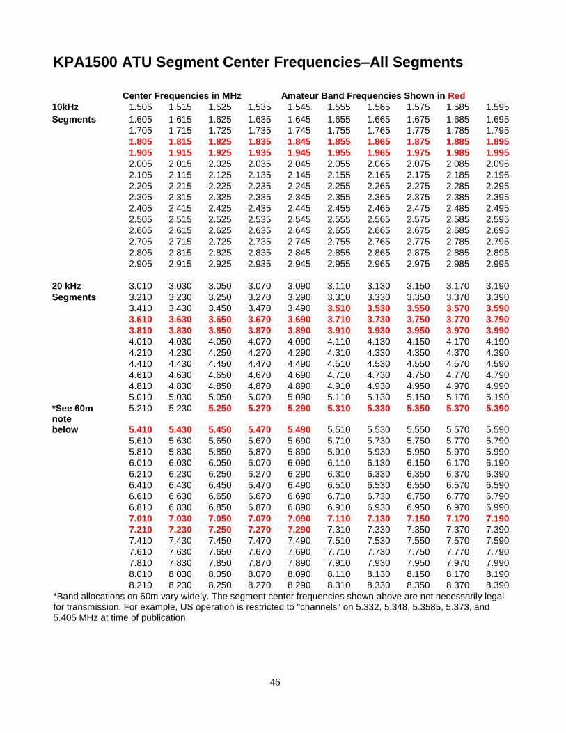
46
KPA1500 ATU Segment Center Frequencies–All Segments
Center Frequencies in MHz Amateur Band Frequencies Shown in Red
10kHz 1.505 1.515 1.525 1.535 1.545 1.555 1.565 1.575 1.585 1.595
Segments 1.605 1.615 1.625 1.635 1.645 1.655 1.665 1.675 1.685 1.695
1.705 1.715 1.725 1.735 1.745 1.755 1.765 1.775 1.785 1.795
1.805 1.815 1.825 1.835 1.845 1.855 1.865 1.875 1.885 1.895
1.905 1.915 1.925 1.935 1.945 1.955 1.965 1.975 1.985 1.995
2.005 2.015 2.025 2.035 2.045 2.055 2.065 2.075 2.085 2.095
2.105 2.115 2.125 2.135 2.145 2.155 2.165 2.175 2.185 2.195
2.205 2.215 2.225 2.235 2.245 2.255 2.265 2.275 2.285 2.295
2.305 2.315 2.325 2.335 2.345 2.355 2.365 2.375 2.385 2.395
2.405 2.415 2.425 2.435 2.445 2.455 2.465 2.475 2.485 2.495
2.505 2.515 2.525 2.535 2.545 2.555 2.565 2.575 2.585 2.595
2.605 2.615 2.625 2.635 2.645 2.655 2.665 2.675 2.685 2.695
2.705 2.715 2.725 2.735 2.745 2.755 2.765 2.775 2.785 2.795
2.805 2.815 2.825 2.835 2.845 2.855 2.865 2.875 2.885 2.895
2.905 2.915 2.925 2.935 2.945 2.955 2.965 2.975 2.985 2.995
20 kHz 3.010 3.030 3.050 3.070 3.090 3.110 3.130 3.150 3.170 3.190
Segments 3.210 3.230 3.250 3.270 3.290 3.310 3.330 3.350 3.370 3.390
3.410 3.430 3.450 3.470 3.490 3.510 3.530 3.550 3.570 3.590
3.610 3.630 3.650 3.670 3.690 3.710 3.730 3.750 3.770 3.790
3.810 3.830 3.850 3.870 3.890 3.910 3.930 3.950 3.970 3.990
4.010 4.030 4.050 4.070 4.090 4.110 4.130 4.150 4.170 4.190
4.210 4.230 4.250 4.270 4.290 4.310 4.330 4.350 4.370 4.390
4.410 4.430 4.450 4.470 4.490 4.510 4.530 4.550 4.570 4.590
4.610 4.630 4.650 4.670 4.690 4.710 4.730 4.750 4.770 4.790
4.810 4.830 4.850 4.870 4.890 4.910 4.930 4.950 4.970 4.990
5.010 5.030 5.050 5.070 5.090 5.110 5.130 5.150 5.170 5.190
*See 60m note
5.210 5.230 5.250 5.270 5.290 5.310 5.330 5.350 5.370 5.390
below 5.410 5.430 5.450 5.470 5.490 5.510 5.530 5.550 5.570 5.590
5.610 5.630 5.650 5.670 5.690 5.710 5.730 5.750 5.770 5.790
5.810 5.830 5.850 5.870 5.890 5.910 5.930 5.950 5.970 5.990
6.010 6.030 6.050 6.070 6.090 6.110 6.130 6.150 6.170 6.190
6.210 6.230 6.250 6.270 6.290 6.310 6.330 6.350 6.370 6.390
6.410 6.430 6.450 6.470 6.490 6.510 6.530 6.550 6.570 6.590
6.610 6.630 6.650 6.670 6.690 6.710 6.730 6.750 6.770 6.790
6.810 6.830 6.850 6.870 6.890 6.910 6.930 6.950 6.970 6.990
7.010 7.030 7.050 7.070 7.090 7.110 7.130 7.150 7.170 7.190
7.210 7.230 7.250 7.270 7.290 7.310 7.330 7.350 7.370 7.390
7.410 7.430 7.450 7.470 7.490 7.510 7.530 7.550 7.570 7.590
7.610 7.630 7.650 7.670 7.690 7.710 7.730 7.750 7.770 7.790
7.810 7.830 7.850 7.870 7.890 7.910 7.930 7.950 7.970 7.990
8.010 8.030 8.050 8.070 8.090 8.110 8.130 8.150 8.170 8.190
8.210 8.230 8.250 8.270 8.290 8.310 8.330 8.350 8.370 8.390
*Band allocations on 60m vary widely. The segment center frequencies shown above are not necessarily legal for transmission. For example, US operation is restricted to "channels" on 5.332, 5.348, 5.3585, 5.373, and 5.405 MHz at time of publication.
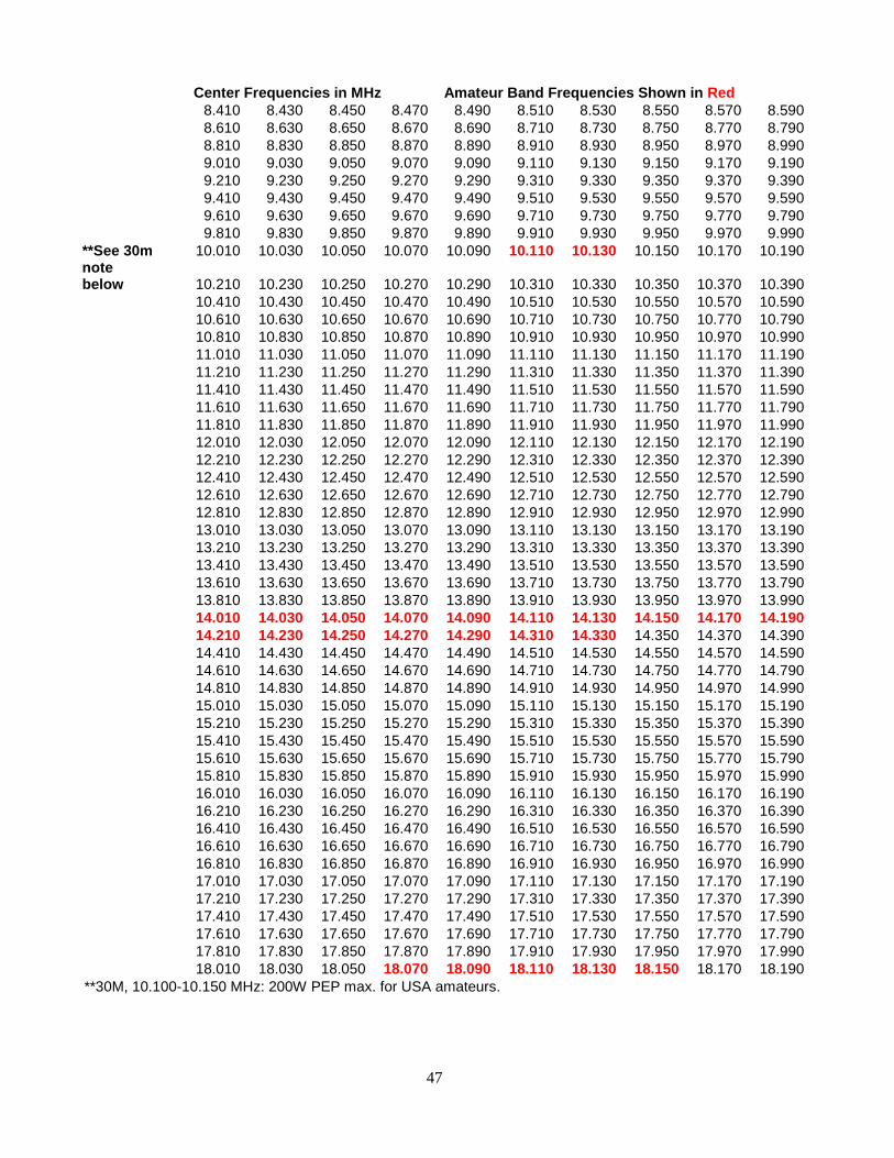
47
Center Frequencies in MHz Amateur Band Frequencies Shown in Red
8.410 8.430 8.450 8.470 8.490 8.510 8.530 8.550 8.570 8.590
8.610 8.630 8.650 8.670 8.690 8.710 8.730 8.750 8.770 8.790
8.810 8.830 8.850 8.870 8.890 8.910 8.930 8.950 8.970 8.990
9.010 9.030 9.050 9.070 9.090 9.110 9.130 9.150 9.170 9.190
9.210 9.230 9.250 9.270 9.290 9.310 9.330 9.350 9.370 9.390
9.410 9.430 9.450 9.470 9.490 9.510 9.530 9.550 9.570 9.590
9.610 9.630 9.650 9.670 9.690 9.710 9.730 9.750 9.770 9.790
9.810 9.830 9.850 9.870 9.890 9.910 9.930 9.950 9.970 9.990
**See 30m note
10.010 10.030 10.050 10.070 10.090 10.110 10.130 10.150 10.170 10.190
below 10.210 10.230 10.250 10.270 10.290 10.310 10.330 10.350 10.370 10.390
10.410 10.430 10.450 10.470 10.490 10.510 10.530 10.550 10.570 10.590
10.610 10.630 10.650 10.670 10.690 10.710 10.730 10.750 10.770 10.790
10.810 10.830 10.850 10.870 10.890 10.910 10.930 10.950 10.970 10.990
11.010 11.030 11.050 11.070 11.090 11.110 11.130 11.150 11.170 11.190
11.210 11.230 11.250 11.270 11.290 11.310 11.330 11.350 11.370 11.390
11.410 11.430 11.450 11.470 11.490 11.510 11.530 11.550 11.570 11.590
11.610 11.630 11.650 11.670 11.690 11.710 11.730 11.750 11.770 11.790
11.810 11.830 11.850 11.870 11.890 11.910 11.930 11.950 11.970 11.990
12.010 12.030 12.050 12.070 12.090 12.110 12.130 12.150 12.170 12.190
12.210 12.230 12.250 12.270 12.290 12.310 12.330 12.350 12.370 12.390
12.410 12.430 12.450 12.470 12.490 12.510 12.530 12.550 12.570 12.590
12.610 12.630 12.650 12.670 12.690 12.710 12.730 12.750 12.770 12.790
12.810 12.830 12.850 12.870 12.890 12.910 12.930 12.950 12.970 12.990
13.010 13.030 13.050 13.070 13.090 13.110 13.130 13.150 13.170 13.190
13.210 13.230 13.250 13.270 13.290 13.310 13.330 13.350 13.370 13.390
13.410 13.430 13.450 13.470 13.490 13.510 13.530 13.550 13.570 13.590
13.610 13.630 13.650 13.670 13.690 13.710 13.730 13.750 13.770 13.790
13.810 13.830 13.850 13.870 13.890 13.910 13.930 13.950 13.970 13.990
14.010 14.030 14.050 14.070 14.090 14.110 14.130 14.150 14.170 14.190
14.210 14.230 14.250 14.270 14.290 14.310 14.330 14.350 14.370 14.390
14.410 14.430 14.450 14.470 14.490 14.510 14.530 14.550 14.570 14.590
14.610 14.630 14.650 14.670 14.690 14.710 14.730 14.750 14.770 14.790
14.810 14.830 14.850 14.870 14.890 14.910 14.930 14.950 14.970 14.990
15.010 15.030 15.050 15.070 15.090 15.110 15.130 15.150 15.170 15.190
15.210 15.230 15.250 15.270 15.290 15.310 15.330 15.350 15.370 15.390
15.410 15.430 15.450 15.470 15.490 15.510 15.530 15.550 15.570 15.590
15.610 15.630 15.650 15.670 15.690 15.710 15.730 15.750 15.770 15.790
15.810 15.830 15.850 15.870 15.890 15.910 15.930 15.950 15.970 15.990
16.010 16.030 16.050 16.070 16.090 16.110 16.130 16.150 16.170 16.190
16.210 16.230 16.250 16.270 16.290 16.310 16.330 16.350 16.370 16.390
16.410 16.430 16.450 16.470 16.490 16.510 16.530 16.550 16.570 16.590
16.610 16.630 16.650 16.670 16.690 16.710 16.730 16.750 16.770 16.790
16.810 16.830 16.850 16.870 16.890 16.910 16.930 16.950 16.970 16.990
17.010 17.030 17.050 17.070 17.090 17.110 17.130 17.150 17.170 17.190
17.210 17.230 17.250 17.270 17.290 17.310 17.330 17.350 17.370 17.390
17.410 17.430 17.450 17.470 17.490 17.510 17.530 17.550 17.570 17.590
17.610 17.630 17.650 17.670 17.690 17.710 17.730 17.750 17.770 17.790
17.810 17.830 17.850 17.870 17.890 17.910 17.930 17.950 17.970 17.990
18.010 18.030 18.050 18.070 18.090 18.110 18.130 18.150 18.170 18.190
**30M, 10.100-10.150 MHz: 200W PEP max. for USA amateurs.
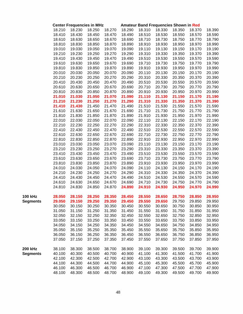
48
Center Frequencies in MHz Amateur Band Frequencies Shown in Red
18.210 18.230 18.250 18.270 18.290 18.310 18.330 18.350 18.370 18.390
18.410 18.430 18.450 18.470 18.490 18.510 18.530 18.550 18.570 18.590
18.610 18.630 18.650 18.670 18.690 18.710 18.730 18.750 18.770 18.790
18.810 18.830 18.850 18.870 18.890 18.910 18.930 18.950 18.970 18.990
19.010 19.030 19.050 19.070 19.090 19.110 19.130 19.150 19.170 19.190
19.210 19.230 19.250 19.270 19.290 19.310 19.330 19.350 19.370 19.390
19.410 19.430 19.450 19.470 19.490 19.510 19.530 19.550 19.570 19.590
19.610 19.630 19.650 19.670 19.690 19.710 19.730 19.750 19.770 19.790
19.810 19.830 19.850 19.870 19.890 19.910 19.930 19.950 19.970 19.990
20.010 20.030 20.050 20.070 20.090 20.110 20.130 20.150 20.170 20.190
20.210 20.230 20.250 20.270 20.290 20.310 20.330 20.350 20.370 20.390
20.410 20.430 20.450 20.470 20.490 20.510 20.530 20.550 20.570 20.590
20.610 20.630 20.650 20.670 20.690 20.710 20.730 20.750 20.770 20.790
20.810 20.830 20.850 20.870 20.890 20.910 20.930 20.950 20.970 20.990
21.010 21.030 21.050 21.070 21.090 21.110 21.130 21.150 21.170 21.190
21.210 21.230 21.250 21.270 21.290 21.310 21.330 21.350 21.370 21.390
21.410 21.430 21.450 21.470 21.490 21.510 21.530 21.550 21.570 21.590
21.610 21.630 21.650 21.670 21.690 21.710 21.730 21.750 21.770 21.790
21.810 21.830 21.850 21.870 21.890 21.910 21.930 21.950 21.970 21.990
22.010 22.030 22.050 22.070 22.090 22.110 22.130 22.150 22.170 22.190
22.210 22.230 22.250 22.270 22.290 22.310 22.330 22.350 22.370 22.390
22.410 22.430 22.450 22.470 22.490 22.510 22.530 22.550 22.570 22.590
22.610 22.630 22.650 22.670 22.690 22.710 22.730 22.750 22.770 22.790
22.810 22.830 22.850 22.870 22.890 22.910 22.930 22.950 22.970 22.990
23.010 23.030 23.050 23.070 23.090 23.110 23.130 23.150 23.170 23.190
23.210 23.230 23.250 23.270 23.290 23.310 23.330 23.350 23.370 23.390
23.410 23.430 23.450 23.470 23.490 23.510 23.530 23.550 23.570 23.590
23.610 23.630 23.650 23.670 23.690 23.710 23.730 23.750 23.770 23.790
23.810 23.830 23.850 23.870 23.890 23.910 23.930 23.950 23.970 23.990
24.010 24.030 24.050 24.070 24.090 24.110 24.130 24.150 24.170 24.190
24.210 24.230 24.250 24.270 24.290 24.310 24.330 24.350 24.370 24.390
24.410 24.430 24.450 24.470 24.490 24.510 24.530 24.550 24.570 24.590
24.610 24.630 24.650 24.670 24.690 24.710 24.730 24.750 24.770 24.790
24.810 24.830 24.850 24.870 24.890 24.910 24.930 24.950 24.970 24.990
100 kHz 28.050 28.150 28.250 28.350 28.450 28.550 28.650 28.750 28.850 28.950
Segments 29.050 29.150 29.250 29.350 29.450 29.550 29.650 29.750 29.850 29.950
30.050 30.150 30.250 30.350 30.450 30.550 30.650 30.750 30.850 30.950
31.050 31.150 31.250 31.350 31.450 31.550 31.650 31.750 31.850 31.950
32.050 32.150 32.250 32.350 32.450 32.550 32.650 32.750 32.850 32.950
33.050 33.150 33.250 33.350 33.450 33.550 33.650 33.750 33.850 33.950
34.050 34.150 34.250 34.350 34.450 34.550 34.650 34.750 34.850 34.950
35.050 35.150 35.250 35.350 35.450 35.550 35.650 35.750 35.850 35.950
36.050 36.150 36.250 36.350 36.450 36.550 36.650 36.750 36.850 36.950
37.050 37.150 37.250 37.350 37.450 37.550 37.650 37.750 37.850 37.950
200 kHz 38.100 38.300 38.500 38.700 38.900 39.100 39.300 39.500 39.700 39.900
Segments 40.100 40.300 40.500 40.700 40.900 41.100 41.300 41.500 41.700 41.900
42.100 42.300 42.500 42.700 42.900 43.100 43.300 43.500 43.700 43.900
44.100 44.300 44.500 44.700 44.900 45.100 45.300 45.500 45.700 45.900
46.100 46.300 46.500 46.700 46.900 47.100 47.300 47.500 47.700 47.900
48.100 48.300 48.500 48.700 48.900 49.100 49.300 49.500 49.700 49.900

49
Center Frequencies in MHz Amateur Band Frequencies Shown in Red
50.100 50.300 50.500 50.700 50.900 51.100 51.300 51.500 51.700 51.900
52.100 52.300 52.500 52.700 52.900 53.100 53.300 53.500 53.700 53.900
54.100 54.300 54.500 54.700 54.900 55.100 55.300 55.500 55.700 55.900
56.100 56.300 56.500 56.700 56.900 57.100 57.300 57.500 57.700 57.900
58.100 58.300 58.500 58.700 58.900 59.100 59.300 59.500 59.700 59.900