Embed Size (px)
Citation preview
NEWTOWN CREEK CHANNEL CONDITION
AND MATERIAL TRANSPORT REPORT
Performed for the New York State Department of Transportation In Support of the
Draft Environmental Impact Statement For the Kosciuszko Bridge Project
Kings County and Queens County, NY
July 2006
Kosciuszko Bridge Project
New York State Department of Transportation
Kosciuszko Bridge Project 1 July 2006
A. OVERVIEW
This report examines the condition of the Newtown Creek navigation channel, ability to ship material on Newtown Creek and any dredging requirements associated with the rehabilitation or replacement of the Kosciuszko Bridge across Newtown Creek at Mile 2.1. The lower portion of Newtown Creek, Sections A through E, has not been dredged since 1950. The last complete survey of Newtown Creek was tabulated from surveys by the US Army Corps of Engineers (USACE) in November 1991. However, several obstructions were removed prior to an “After Removal Condition Survey” (published May 31, 2002) performed for the USACE in a portion of Section D. Comparison of depth data between 1991 and 2002 for similar areas showed little evidence of degradation of the channel depth over the 10-year period. In a few areas it was estimated that the bottom soils shifted slightly. The Congressionally-authorized dredged channel size for Sections A through E affecting the bridge is generally 39.6 m (130 ft) wide and 6.7 m (22 ft) deep at mean lower low water (MLLW). The area to the west of the Kosciuszko Bridge appears to have a minimum 3.35 m (11 ft) channel depth at MLLW available for a horizontal distance of 45.72 m to 51.82 m (150 to 170 ft). It is recommended that either soundings or a bar sweep at the deepest depth be required for Sections A through E of Newtown Creek just prior to major construction to verify that conditions have not changed.
Elements that could be critical to the issue of channel depth are the draft requirements of marine equipment servicing the construction site and more specifically ocean-going barges delivering bridge segments or other material for the various design alternatives. The most critical issue was considered the ability to deliver prestressed concrete segments by barge to the bridge site. All barge loads required less than 3.2 m (10.5 ft) draft and in some cases drafts as low as 2.29 m (7.5 ft) for maximum deck loads.
B. NAVIGATION CHANNEL
B.1. Channel Depths and Widths
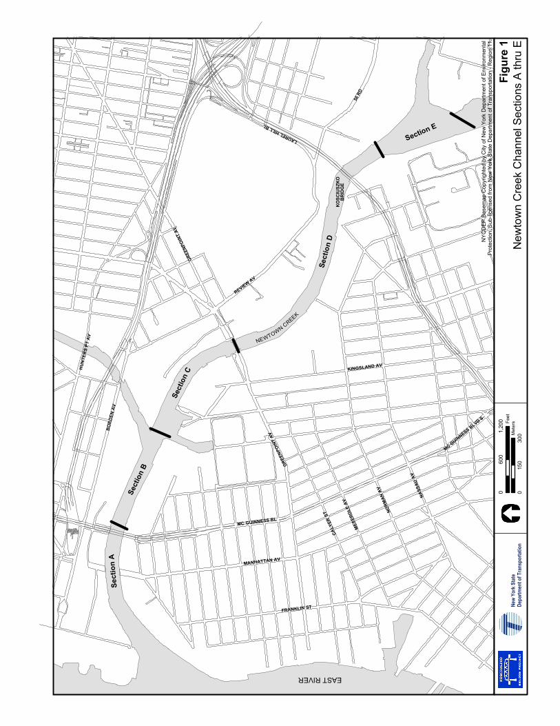
The last complete survey of Newtown Creek was tabulated from surveys by USACE in November 1991. The controlling depths from seaward are provided in feet at MLLW. Of interest for this bridge replacement is information dealing with Channel Sections A thru E (see Figure 1), which includes the area off Maspeth Creek. Table 1, below, provides the technical data regarding each Channel Section as published in National Oceanographic and Atmospheric Administration (NOAA) Chart 12338 9th edition, March 2003.
Sect
ion
A
Sect
ion
B
Sect
ion
C
Sect
ion
D
Section E
MC GUINNESS BL
GRE
ENPO
INT
AV
NASS
AU A
V
NORM
AN A
V
REVIEW AV
KINGSLAND AV
MANHATTAN AV
FRANKLIN ST
MES
ERO
LE A
V
CALY
ER S
T
MC GUINNESS BLVD S
GRE
ENPO
INT
AV
HU
NTE
RS
PT A
V
BO
RD
EN A
V
56 R
D
LAUREL HILL BL
KO
SCIU
SZK
OB
RID
GE
NEWTOWN CREEK
EAST RIVER
NY
CD
EP B
asem
ap C
opyr
ight
ed b
y C
ity o
f New
Yor
k D
epar
tmen
t of E
nviro
nmen
tal
Prot
ectio
n, S
ub-li
cens
ed fr
om N
ew Y
ork
Sta
te D
epar
tmen
t of T
rans
porta
tion
- Reg
ion
11.
Figu
re 1
New
tow
n C
reek
Cha
nnel
Sec
tions
A th
ru E
New
York
Sta
teDe
partm
ent o
f Tra
nspo
rtatio
n
060
01,
200 Fe
et
015
030
0Met
ers
Newtown Creek Channel Condition and Material Transport Report
Kosciuszko Bridge Project 2 July 2006
TABLE 1: NEWTOWN CREEK CHANNEL DEPTH AT MLLW
Project Dimensions*
Channel Section
Left Outside Quarter
Middle Half of
Channel
Right Outside Quarter
Survey Date
Width (Feet)
Length (Nautical Miles)
Depth MLLW (Feet)
A 9.1 12.0 15.5 11/91; 8/00 240-130 0.53 23
B 17.5 15.3 10.9 11/91 130 0.30 23
C 16.8 17.8 16.8 11/91 130 0.37 23
D (see note) 8.7 13.4 10.2 5/31/2002 130 0.78 23
E 13.1 14.5 11.8 11/91 130-300 0.23 23 Note: Area to west of Kosciuszko Bridge surveyed by USACE on May 31, 2002, these soundings refers to MLW which are 2.01 Below NGVD (1929). The soundings were taken after removal of obstructions in Channel Section D, discussed below. * Project dimensions refers to the federally permitted allowable dredged channel size.
A comparison of the 2002 Soundings Report to the November 1991 report, indicates little evidence of extensive degradation of the channel depth over the 10-year period. In a few areas it was estimated that the bottom soils shifted slightly due to the current and tug and barge traffic movement. However, it is estimated that the general change was less than +/- 0.15 m (0.5 ft). A minimum 3.35 m (11 ft) channel depth was available for a horizontal distance of 46 m to 52 m (150 to 170 ft). In section A the 3.35 m (11 ft) depth could be found for a horizontal width of about 190 feet except at the Pulaski Bridge, where the bridge abutments narrow the channel. In section B the 3.35 m (11 ft) channel depth extends over the 40 m (190 ft) width except at the entrance to Dutch Kills where it narrowed to about 52 m (170 ft) for approximately 30 m (100 ft). In Section C, the 3.35 m (11 ft) depth was maintained for over 61 m (200 ft) width except for at the JJ Byrne Memorial Bridge (Greenpoint Avenue).
B.2. Newtown Creek Dredging and Obstruction Removal History
No dredging in Newtown Creek has been performed since April 1974, over 30 years ago, which was performed on the upper portion. The lower portion of Newtown Creek, Sections A through E, for which we are primarily interested, have not been dredged since 1950.
However, it is important to note that obstructions were removed prior to May 2002 and an “After Removal Condition Survey” was performed by the USACE in a portion of Section D. The Condition Survey identifies the following six reported obstruction areas on the soundings sheet, although it is unclear whether the channel has been cleared of obstructions:
1. Barge Location
2. Crane Barge Location
3. Crane Barge Location
4. Possible Stone Location
5. Barge location (A)
6. Barge Location (B)
Newtown Creek Channel Condition and Material Transport Report
Kosciuszko Bridge Project 3 July 2006
C. EVALUATION OF PROPOSED STAGING AREAS
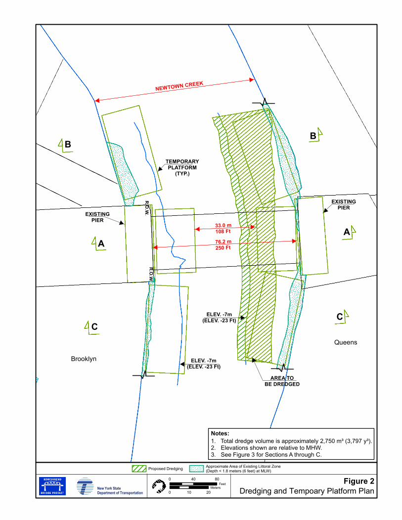
The proposed new concrete segmental bridge construction would be 1,174 m (3,850 ft) in length. To facilitate the construction, it is proposed to bring precast concrete segments to the site by barge. The segments for the main span could be supplied by barge and lifted directly into place or placed on land and rehandled. For the approach spans, typical cantilever construction with a self launching gantry would be feasible. Two staging areas are proposed along Newtown Creek adjacent to the bridge, one in Brooklyn and one in Queens.
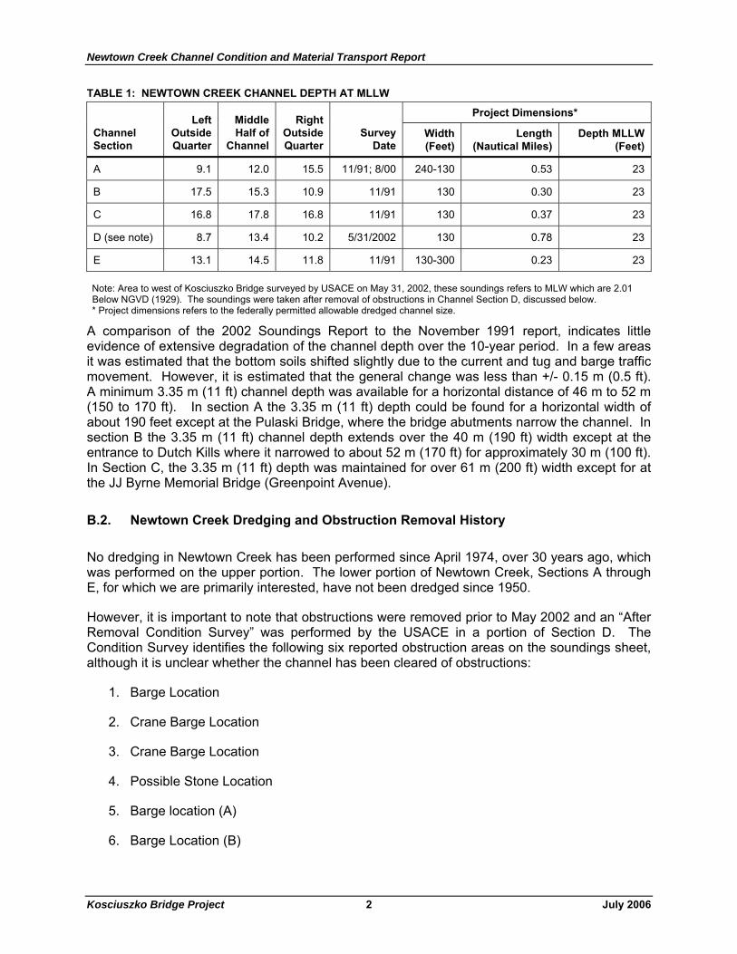
In order to minimize dredging, offloading platforms are proposed to be installed in the creek, as shown on Figures 2 and 3. Limited dredging will still be required on the Queens bank of Newtown Creek.
C.1. Brooklyn Staging Area
The shoreline in Brooklyn adjacent to the bridge consists of a bank area of approximately 6 to 9 m (20 to 30 ft) wide at Mean High Water (MHW). The bank consists of concrete spoil, rip-rap, and vegetation. The edge of the channel with a 3.35 m (11 ft) depth varies from about 15 to 21 m (50 to 70 ft) from the bottom edge of the bank. It is estimated that within 9 to 12 m (30 to 40 ft) of the bottom of the bank, the depths are 1.5 m (5 ft) or less.
C.2. Queens Staging Area
The shoreline in Queens adjacent to the bridge consists of a bank area approximately 3 to 4.7 m (10 to 15 ft) wide at MHW for the first 55 m (180 ft). The bank consists of concrete rubble and vegetation. The additional 37 m (120 ft) is a combination of wood bulkhead and steel sheet piling. This type of bulkhead face extends for over 91 m (300 ft). The edge of the channel with a 3.35 m (11 ft) depth varies from approximately 12 m to 24 m (40 to 80 ft) from the bottom edge of the concrete rubble portion of the irregular bank. Along the bulkhead section, it varies from 9 to 12 m (30 to 40 ft) for the initial 61 m (200 ft) and then slopes out to about 18 m (60 ft) for the next 60 m (200 ft).
C.3. Origin or Manufacturer of Concrete Bridge Sections
The actual origin or manufacturer of concrete bridge sections will not be known until a construction contract is let. However, when evaluating marine equipment availability and the acceptability of the waterway to handle waterborne delivery, two options are considered:
1. The first option would be to acquire the sections from a foreign manufacturer requiring delivery by ship, through the Port of New York/New Jersey, and then offload the sections from the ships to deck barges for eventual transport to the project site. Though this is a possibility, it is unlikely to be the most cost effective as it would require multiple handlings or transfers of the sections.
2. The second, and likely more cost effective option, would be to use a manufacturer on the United State’s East Coast or Gulf Coast. Transportation to the bridge site would be facilitated by Coast Guard-certified and American Bureau of Shipping-inspected ocean or coastwise barges.
ELEV. -7m(ELEV. -23 Ft)
ELEV. -7m(ELEV. -23 Ft)
AREA TOBE DREDGED
EXISTINGPIER
AR
.O.W
.R
.O.W
.
TEMPORARYPLATFORM
(TYP.)
EXISTINGPIER
A
BB
CC
33.0 m108 Ft
76.2 m250 Ft
NEWTOWN CREEK
Brooklyn
Queens
Figure 2Dredging and Tempoary Platform Plan
1. Total dredge volume is approximately 2,750 m³ (3,797 y³).2. Elevations shown are relative to MHW.3. See Figure 3 for Sections A through C.
Notes:
New York StateDepartment of Transportation
Proposed Dredging Approximate Area of Existing Littoral Zone(Depth < 1.8 meters (6 feet) at MLW)
0 40 80Feet
0 10 20Meters
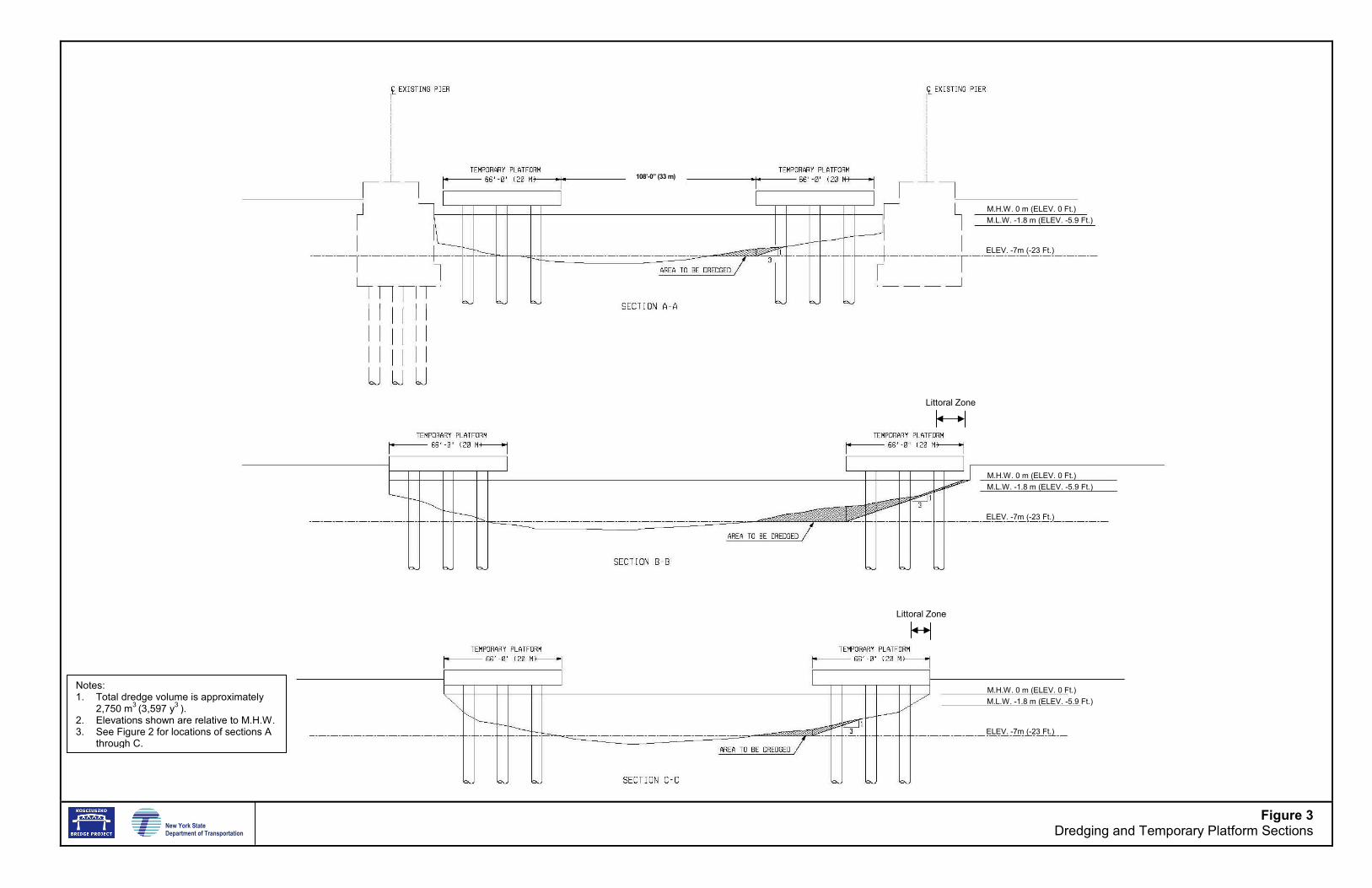
Notes: 1. Total dredge volume is approximately
2,750 m3 (3,597 y3 ). 2. Elevations shown are relative to M.H.W. 3. See Figure 2 for locations of sections A
through C.
108’-0” (33 m)
M.H.W. 0 m (ELEV. 0 Ft.) M.L.W. -1.8 m (ELEV. -5.9 Ft.)
ELEV. -7m (-23 Ft.)
M.H.W. 0 m (ELEV. 0 Ft.) M.L.W. -1.8 m (ELEV. -5.9 Ft.)
ELEV. -7m (-23 Ft.)
M.H.W. 0 m (ELEV. 0 Ft.) M.L.W. -1.8 m (ELEV. -5.9 Ft.)
ELEV. -7m (-23 Ft.)
New York State Department of Transportation
Figure 3Dredging and Temporary Platform Sections
Littoral Zone
Littoral Zone
Newtown Creek Channel Condition and Material Transport Report
Kosciuszko Bridge Project 4 July 2006
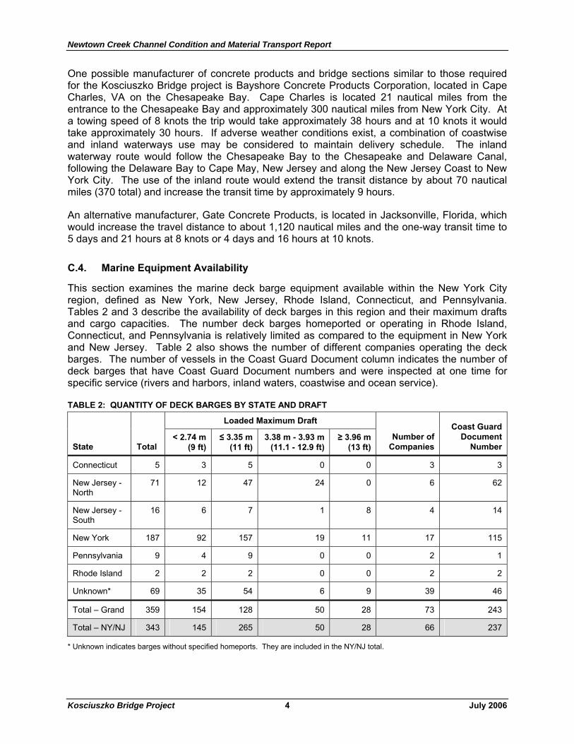
One possible manufacturer of concrete products and bridge sections similar to those required for the Kosciuszko Bridge project is Bayshore Concrete Products Corporation, located in Cape Charles, VA on the Chesapeake Bay. Cape Charles is located 21 nautical miles from the entrance to the Chesapeake Bay and approximately 300 nautical miles from New York City. At a towing speed of 8 knots the trip would take approximately 38 hours and at 10 knots it would take approximately 30 hours. If adverse weather conditions exist, a combination of coastwise and inland waterways use may be considered to maintain delivery schedule. The inland waterway route would follow the Chesapeake Bay to the Chesapeake and Delaware Canal, following the Delaware Bay to Cape May, New Jersey and along the New Jersey Coast to New York City. The use of the inland route would extend the transit distance by about 70 nautical miles (370 total) and increase the transit time by approximately 9 hours.
An alternative manufacturer, Gate Concrete Products, is located in Jacksonville, Florida, which would increase the travel distance to about 1,120 nautical miles and the one-way transit time to 5 days and 21 hours at 8 knots or 4 days and 16 hours at 10 knots.
C.4. Marine Equipment Availability
This section examines the marine deck barge equipment available within the New York City region, defined as New York, New Jersey, Rhode Island, Connecticut, and Pennsylvania. Tables 2 and 3 describe the availability of deck barges in this region and their maximum drafts and cargo capacities. The number deck barges homeported or operating in Rhode Island, Connecticut, and Pennsylvania is relatively limited as compared to the equipment in New York and New Jersey. Table 2 also shows the number of different companies operating the deck barges. The number of vessels in the Coast Guard Document column indicates the number of deck barges that have Coast Guard Document numbers and were inspected at one time for specific service (rivers and harbors, inland waters, coastwise and ocean service).
TABLE 2: QUANTITY OF DECK BARGES BY STATE AND DRAFT
Loaded Maximum Draft
State Total < 2.74 m
(9 ft) ≤ 3.35 m
(11 ft) 3.38 m - 3.93 m
(11.1 - 12.9 ft) ≥ 3.96 m
(13 ft) Number of
Companies
Coast Guard Document
Number
Connecticut 5 3 5 0 0 3 3
New Jersey - North
71 12 47 24 0 6 62
New Jersey - South
16 6 7 1 8 4 14
New York 187 92 157 19 11 17 115
Pennsylvania 9 4 9 0 0 2 1
Rhode Island 2 2 2 0 0 2 2
Unknown* 69 35 54 6 9 39 46
Total – Grand 359 154 128 50 28 73 243
Total – NY/NJ 343 145 265 50 28 66 237
* Unknown indicates barges without specified homeports. They are included in the NY/NJ total.
Newtown Creek Channel Condition and Material Transport Report
Kosciuszko Bridge Project 5 July 2006
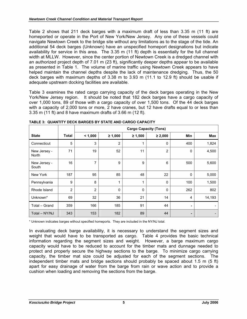
Table 2 shows that 211 deck barges with a maximum draft of less than 3.35 m (11 ft) are homeported or operate in the Port of New York/New Jersey. Any one of these vessels could navigate Newtown Creek to the bridge site without any limitations as to the stage of the tide. An additional 54 deck barges (Unknown) have an unspecified homeport designations but indicate availability for service in this area. The 3.35 m (11 ft) depth is essentially for the full channel width at MLLW. However, since the center portion of Newtown Creek is a dredged channel with an authorized project depth of 7.01 m (23 ft), significantly deeper depths appear to be available as presented in Table 1. The volume of marine traffic using Newtown Creek appears to have helped maintain the channel depths despite the lack of maintenance dredging. Thus, the 50 deck barges with maximum depths of 3.38 m to 3.93 m (11.1 to 12.9 ft) should be usable if adequate upstream docking facilities are available.
Table 3 examines the rated cargo carrying capacity of the deck barges operating in the New York/New Jersey region. It should be noted that 182 deck barges have a cargo capacity of over 1,000 tons, 89 of those with a cargo capacity of over 1,500 tons. Of the 44 deck barges with a capacity of 2,000 tons or more, 2 have cranes, but 12 have drafts equal to or less than 3.35 m (11 ft) and 8 have maximum drafts of 3.66 m (12 ft).
TABLE 3: QUANTITY DECK BARGES BY STATE AND CARGO CAPACITY
Cargo Capacity (Tons)
State Total < 1,000 ≥ 1,000 ≥ 1,500 ≥ 2,000 Min Max
Connecticut 5 3 2 1 0 400 1,824
New Jersey - North
71 19 52 11 2 0 4,500
New Jersey - South
16 7 9 9 6 500 5,600
New York 187 95 85 48 22 0 5,000
Pennsylvania 9 8 1 1 0 100 1,500
Rhode Island 2 2 0 0 0 262 802
Unknown* 69 32 36 21 14 4 14,193
Total – Grand 359 166 185 91 44 - -
Total – NY/NJ 343 153 182 89 44 - -
* Unknown indicates barges without specified homeports. They are included in the NY/NJ total.
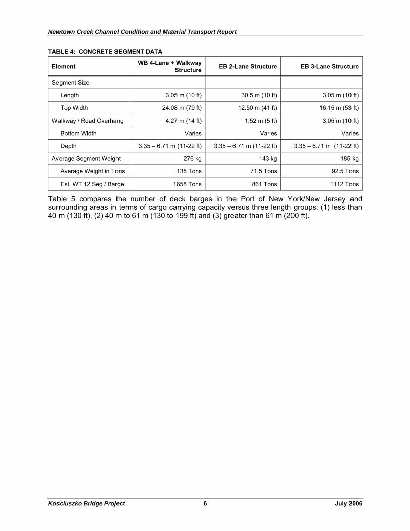
In evaluating deck barge availability, it is necessary to understand the segment sizes and weight that would have to be transported as cargo. Table 4 provides the basic technical information regarding the segment sizes and weight. However, a barge maximum cargo capacity would have to be reduced to account for the timber mats and dunnage needed to protect and properly secure the highway sections to the barge. To minimize cargo carrying capacity, the timber mat size could be adjusted for each of the segment sections. The independent timber mats and bridge sections should probably be spaced about 1.5 m (5 ft) apart for easy drainage of water from the barge from rain or wave action and to provide a cushion when loading and removing the sections from the barge.
Newtown Creek Channel Condition and Material Transport Report
Kosciuszko Bridge Project 6 July 2006
TABLE 4: CONCRETE SEGMENT DATA
Element WB 4-Lane + Walkway Structure EB 2-Lane Structure EB 3-Lane Structure
Segment Size
Length 3.05 m (10 ft) 30.5 m (10 ft) 3.05 m (10 ft)
Top Width 24.08 m (79 ft) 12.50 m (41 ft) 16.15 m (53 ft)
Walkway / Road Overhang 4.27 m (14 ft) 1.52 m (5 ft) 3.05 m (10 ft)
Bottom Width Varies Varies Varies
Depth 3.35 – 6.71 m (11-22 ft) 3.35 – 6.71 m (11-22 ft) 3.35 – 6.71 m (11-22 ft)
Average Segment Weight 276 kg 143 kg 185 kg
Average Weight in Tons 138 Tons 71.5 Tons 92.5 Tons
Est. WT 12 Seg / Barge 1658 Tons 861 Tons 1112 Tons
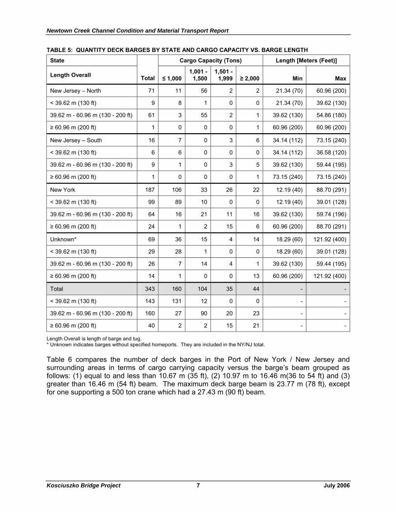
Table 5 compares the number of deck barges in the Port of New York/New Jersey and surrounding areas in terms of cargo carrying capacity versus three length groups: (1) less than 40 m (130 ft), (2) 40 m to 61 m (130 to 199 ft) and (3) greater than 61 m (200 ft).
Newtown Creek Channel Condition and Material Transport Report
Kosciuszko Bridge Project 7 July 2006
TABLE 5: QUANTITY DECK BARGES BY STATE AND CARGO CAPACITY VS. BARGE LENGTH
State Cargo Capacity (Tons) Length [Meters (Feet)]
Length Overall Total ≤ 1,000 1,001 -
1,500 1,501 -
1,999 ≥ 2,000 Min Max
New Jersey – North 71 11 56 2 2 21.34 (70) 60.96 (200)
< 39.62 m (130 ft) 9 8 1 0 0 21.34 (70) 39.62 (130)
39.62 m - 60.96 m (130 - 200 ft) 61 3 55 2 1 39.62 (130) 54.86 (180)
≥ 60.96 m (200 ft) 1 0 0 0 1 60.96 (200) 60.96 (200)
New Jersey – South 16 7 0 3 6 34.14 (112) 73.15 (240)
< 39.62 m (130 ft) 6 6 0 0 0 34.14 (112) 36.58 (120)
39.62 m - 60.96 m (130 - 200 ft) 9 1 0 3 5 39.62 (130) 59.44 (195)
≥ 60.96 m (200 ft) 1 0 0 0 1 73.15 (240) 73.15 (240)
New York 187 106 33 26 22 12.19 (40) 88.70 (291)
< 39.62 m (130 ft) 99 89 10 0 0 12.19 (40) 39.01 (128)
39.62 m - 60.96 m (130 - 200 ft) 64 16 21 11 16 39.62 (130) 59.74 (196)
≥ 60.96 m (200 ft) 24 1 2 15 6 60.96 (200) 88.70 (291)
Unknown* 69 36 15 4 14 18.29 (60) 121.92 (400)
< 39.62 m (130 ft) 29 28 1 0 0 18.29 (60) 39.01 (128)
39.62 m - 60.96 m (130 - 200 ft) 26 7 14 4 1 39.62 (130) 59.44 (195)
≥ 60.96 m (200 ft) 14 1 0 0 13 60.96 (200) 121.92 (400)
Total 343 160 104 35 44 - -
< 39.62 m (130 ft) 143 131 12 0 0 - -
39.62 m - 60.96 m (130 - 200 ft) 160 27 90 20 23 - -
≥ 60.96 m (200 ft) 40 2 2 15 21 - -
Length Overall is length of barge and tug. * Unknown indicates barges without specified homeports. They are included in the NY/NJ total.
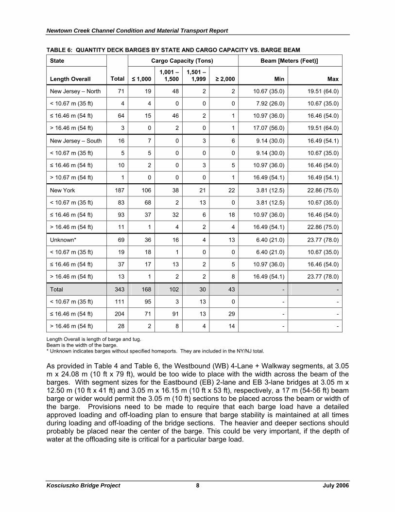
Table 6 compares the number of deck barges in the Port of New York / New Jersey and surrounding areas in terms of cargo carrying capacity versus the barge’s beam grouped as follows: (1) equal to and less than 10.67 m (35 ft), (2) 10.97 m to 16.46 m(36 to 54 ft) and (3) greater than 16.46 m (54 ft) beam. The maximum deck barge beam is 23.77 m (78 ft), except for one supporting a 500 ton crane which had a 27.43 m (90 ft) beam.
Newtown Creek Channel Condition and Material Transport Report
Kosciuszko Bridge Project 8 July 2006
TABLE 6: QUANTITY DECK BARGES BY STATE AND CARGO CAPACITY VS. BARGE BEAM
State Cargo Capacity (Tons) Beam [Meters (Feet)]
Length Overall Total ≤ 1,000 1,001 –
1,500 1,501 –
1,999 ≥ 2,000 Min Max
New Jersey – North 71 19 48 2 2 10.67 (35.0) 19.51 (64.0)
< 10.67 m (35 ft) 4 4 0 0 0 7.92 (26.0) 10.67 (35.0)
≤ 16.46 m (54 ft) 64 15 46 2 1 10.97 (36.0) 16.46 (54.0)
> 16.46 m (54 ft) 3 0 2 0 1 17.07 (56.0) 19.51 (64.0)
New Jersey – South 16 7 0 3 6 9.14 (30.0) 16.49 (54.1)
< 10.67 m (35 ft) 5 5 0 0 0 9.14 (30.0) 10.67 (35.0)
≤ 16.46 m (54 ft) 10 2 0 3 5 10.97 (36.0) 16.46 (54.0)
> 10.67 m (54 ft) 1 0 0 0 1 16.49 (54.1) 16.49 (54.1)
New York 187 106 38 21 22 3.81 (12.5) 22.86 (75.0)
< 10.67 m (35 ft) 83 68 2 13 0 3.81 (12.5) 10.67 (35.0)
≤ 16.46 m (54 ft) 93 37 32 6 18 10.97 (36.0) 16.46 (54.0)
> 16.46 m (54 ft) 11 1 4 2 4 16.49 (54.1) 22.86 (75.0)
Unknown* 69 36 16 4 13 6.40 (21.0) 23.77 (78.0)
< 10.67 m (35 ft) 19 18 1 0 0 6.40 (21.0) 10.67 (35.0)
≤ 16.46 m (54 ft) 37 17 13 2 5 10.97 (36.0) 16.46 (54.0)
> 16.46 m (54 ft) 13 1 2 2 8 16.49 (54.1) 23.77 (78.0)
Total 343 168 102 30 43 - -
< 10.67 m (35 ft) 111 95 3 13 0 - -
≤ 16.46 m (54 ft) 204 71 91 13 29 - -
> 16.46 m (54 ft) 28 2 8 4 14 - -
Length Overall is length of barge and tug. Beam is the width of the barge. * Unknown indicates barges without specified homeports. They are included in the NY/NJ total.
As provided in Table 4 and Table 6, the Westbound (WB) 4-Lane + Walkway segments, at 3.05 m x 24.08 m (10 ft x 79 ft), would be too wide to place with the width across the beam of the barges. With segment sizes for the Eastbound (EB) 2-lane and EB 3-lane bridges at 3.05 m x 12.50 m (10 ft x 41 ft) and 3.05 m x 16.15 m (10 ft x 53 ft), respectively, a 17 m (54-56 ft) beam barge or wider would permit the 3.05 m (10 ft) sections to be placed across the beam or width of the barge. Provisions need to be made to require that each barge load have a detailed approved loading and off-loading plan to ensure that barge stability is maintained at all times during loading and off-loading of the bridge sections. The heavier and deeper sections should probably be placed near the center of the barge. This could be very important, if the depth of water at the offloading site is critical for a particular barge load.
Newtown Creek Channel Condition and Material Transport Report
Kosciuszko Bridge Project 9 July 2006
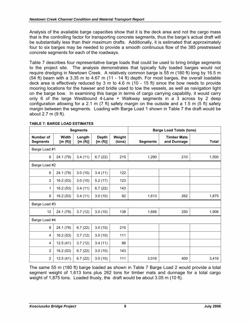
Analysis of the available barge capacities show that it is the deck area and not the cargo mass that is the controlling factor for transporting concrete segments, thus the barge’s actual draft will be substantially less than their maximum drafts. Additionally, it is estimated that approximately four to six barges may be needed to provide a smooth continuous flow of the 385 prestressed concrete segments for each of the roadways.
Table 7 describes four representative barge loads that could be used to bring bridge segments to the project site. The analysis demonstrates that typically fully loaded barges would not require dredging in Newtown Creek. A relatively common barge is 55 m (180 ft) long by 16.5 m (54 ft) beam with a 3.35 m to 4.67 m (11 - 14 ft) depth. For most barges, the overall loadable deck area is effectively reduced by 3 m to 4.6 m (10 - 15 ft) since the bow needs to provide mooring locations for the hawser and bridle used to tow the vessels, as well as navigation light on the barge bow. In examining this barge in terms of cargo carrying capability, it would carry only 6 of the large Westbound 4-Lane + Walkway segments in a 3 across by 2 deep configuration allowing for a 2.1 m (7 ft) safety margin on the outside and a 1.5 m (5 ft) safety margin between the segments. Loading with Barge Load 1 shown in Table 7 the draft would be about 2.7 m (9 ft).
TABLE 7: BARGE LOAD ESTIMATES
Segments Barge Load Totals (tons)
Number of Segments
Width [m (ft)]
Length [m (ft)]
Depth [m (ft)]
Weight (tons) Segments
Timber Mats and Dunnage Total
Barge Load #1
6 24.1 (79) 3.4 (11) 6.7 (22) 215 1,290 210 1,500
Barge Load #2
6 24.1 (79) 3.0 (10) 3.4 (11) 122
2 16.2 (53) 3.0 (10) 5.2 (17) 123
1 16.2 (53) 3.4 (11) 6.7 (22) 143
6 16.2 (53) 3.4 (11) 3.0 (10) 82 1,613 262 1,875
Barge Load #3
12 24.1 (79) 3.7 (12) 3.0 (10) 138 1,656 250 1,906
Barge Load #4
8 24.1 (79) 6.7 (22) 3.0 (10) 215
4 16.2 (53) 3.7 (12) 3.0 (10) 111
4 12.5 (41) 3.7 (12) 3.4 (11) 86
2 16.2 (53) 6.7 (22) 3.0 (10) 143
2 12.5 (41) 6.7 (22) 3.0 (10) 111 3,016 400 3,416
The same 55 m (180 ft) barge loaded as shown in Table 7 Barge Load 2 would provide a total segment weight of 1,613 tons plus 262 tons for timber mats and dunnage for a total cargo weight of 1,875 tons. Loaded thusly, the draft would be about 3.05 m (10 ft).
Newtown Creek Channel Condition and Material Transport Report
Kosciuszko Bridge Project 10 July 2006
The same 55 m (180 ft) barge loaded as shown in Table 7 Barge Load 3 would result in 1,656 tons and assuming approximately 250 tons for timber mats and dunnage for supports and hold downs, the total cargo weight would be 1,906 tons. At that cargo capacity the barge would have a draft of about 3.05 m (10 ft) or less.
Barge Load 4 shows a possible load of segments on a larger 76.2 m x 21.95 m x 3.89 m (250 ft x 72 ft x 12’-9”). This would be a desirable barge because it could permit loading of 4 segments across the beam. The barge is designed to carry 5,312 tons and not exceed its coastwise loadline at a draft of 3.89 m (12’-9”). It is estimated that this barge would have a draft of about 2.44 m (8 ft).
C.5. Conclusion
The existing channel in Newtown Creek is likely deep enough to accommodate local barges fully loaded with concrete segments without requiring dredging, except at the Queens bank under the Kosciuszko Bridge. However, the channel should be surveyed and the fathometer report should be included in final design documents to insure that the contractors bidding on the project are fully aware of channel depths and conditions.


![The Newtown bee. (Newtown, Conn.) 1907-01-11 [p 4]. · Funeral uirector Meigs & Co. 'astore, this week C. E. Gilbert was home from Bridge-and on sale as follows: Advanced on, Dec](https://img.pdfslide.us/doc/110x75/5fc492a126f58c390514da4a/the-newtown-bee-newtown-conn-1907-01-11-p-4-funeral-uirector-meigs-.jpg)