Embed Size (px)
Citation preview
1
MRI-128-F4G-PSE/24
User’s Manual
Version 1.1
Industrial Managed
PoE Plus Ethernet Switch

2
Copyright Notice
Copyright 2013 Westermo Teleindustri AB
All rights reserved.
Reproduction in any form or by any means without permission is prohibited.

3
Federal Communications Commission (FCC) Statement
This equipment has been tested and found to comply with the limits for a Class A
digital device, pursuant to Part 15 of the FCC Rules. These limits are designed to
provide reasonable protection against harmful interference when the equipment is
operated in a commercial environment. This equipment generates, uses, and can
radiate radio frequency energy and, if not installed and used in accordance with the
instruction manual, may cause harmful interference to radio communications.
Operation of this equipment in a residential area is likely to cause harmful
interference in which case the user will be required to correct the interference at his
expense.
The user is cautioned that changes and modifications made to the equipment
without approval of the manufacturer could void the user’s authority to operate this
equipment.

Index 1 Introduction .......................................................................................................... 2
1.1 Overview .................................................................................................... 2
1.2 Major Features ........................................................................................... 2
1.3 Package List ................................................................................................ 3
2 Hardware Installation ............................................................................................ 4
2.1 Hardware Introduction .............................................................................. 4
2.2 Wiring Power Inputs .................................................................................. 5
2.3 Power Supply Specifications ...................................................................... 6
2.4 Wiring Digital Output ................................................................................. 7
2.5 Wiring Earth Ground .................................................................................. 7
2.6 Wiring Fast Ethernet Ports ......................................................................... 8
2.7 Wiring Combo Ports ................................................................................... 9
2.8 Wiring Fiber Ports ...................................................................................... 9
2.9 Data and Power Ports ................................................................................ 9
2.10 Wiring RS-232 Console Cable ................................................................... 10
2.11 Rack Mounting Installation ...................................................................... 10
2.12 Safety Warning ......................................................................................... 11
3 Preparation for Management ............................................................................. 12
3.1 Preparation for Serial Console ................................................................. 12
3.2 Preparation for Web Interface ................................................................. 13
3.3 Preparation for Telnet Console ................................................................ 15
4 Feature Configuration ......................................................................................... 18
4.1 Command Line Interface Introduction ..................................................... 18
4.2 Basic Setting ............................................................................................. 24
4.3 Port Configuration .................................................................................... 46
4.4 Power over Ethernet ................................................................................ 58
4.5 Network Redundancy ............................................................................... 70
4.6 VLAN ......................................................................................................... 91
4.7 Private VLAN .......................................................................................... 103
4.8 Traffic Prioritization ................................................................................ 110
4.9 Multicast Filtering .................................................................................. 116
4.10 SNMP ...................................................................................................... 122
4.11 Security .................................................................................................. 126
4.12 Warning .................................................................................................. 138
4.13 Monitor and Diag ................................................................................... 149
4.14 Device Front Panel ................................................................................. 159

1
4.15 Save to Flash ........................................................................................... 160
4.16 Logout .................................................................................................... 161
5 Appendix ........................................................................................................... 162
5.1 Pin Assignment of the RS-232 Console Cable ........................................ 162
5.2 Private MIB ............................................................................................. 163
5.3 Revision History...................................................................................... 164
2
1 Introduction
Welcome to MRI-128-F4G-PSE/24 Industrial Managed PoE Plus Switch User
Manual. Following topics are covered in this chapter:
1.1 Overview
1.2 Major Features
1.3 Package Checklist
1.1 Overview
MRI-128-F4G-PSE/24 is rackmount High-Port Density and Gigabit Managed
Industrial PoE Switch, designed exclusively for highly critical PoE applications
such as real time IP video surveillance with high resolution quality and the
evolving wireless communication systems such as Wimax and 802.11 a/b/g/n
Access Points.The 24 Fast Ethernet PoE injector ports of the switch can deliver
15.4W by IEEE 802.3af or 30W by the High Power PoE IEEE 802.3at.
The 4 Gigabit Ethernet ports provide high speed uplink to connect with higher
level backbone switches. With the MSR network redundancy technology, the
switches can aggregate up to 12 fast ethernet and 2 gigabit rings while
providing high quality data transmission with less than 300ms network
recovery time. Furthermore, to ensure the traffic switching without data loss
and blocking, the switch provides 12.8G backplane with the integtrated
non-blocking switching function. It incorporates LLDP function and perfectly
works with the NMS for allowing administrators to automatically discover
devices and efficiently manage the industrial network performance in large
scale surveillance networks. To further ensure the non-stop power delivery, the
switch supports dual 48VDC power inputs and provides alarm relay output
signaling function. For high voltage requiring applications the PoE switch
provides extra 90~264VAC or 127~370VDC power supply capability.
With the advanced Layer2 management features including IGMP
Query/Snooping, DHCP, 256 VLAN, QoS, LACP, LPLD, etc. and the corrosion
resistant robust design, the switch highly outstands from other PoE switches
and becomes the revolutionary solution for industrial surveillance applications.
1.2 Major Features
3
Westermo MRI-128-F4G-PSE/24 product has the following features:
Up to 24 10/100 BaseTX and 4 Gigabit uplink ports
Up to 24 ports support both 15.4W IEEE 802.3af and the latest 30W high
power IEEE 802.3at, including 2-event and LLDP classification
Flexible-bandwidth and long-distance data transmission by SFP transceivers
Total power budget is 568W
LPLD (Link Partner Live Detect Function) for reliable PoE connection
through Active Powered Device status detection and auto reset function
12.8G Non-Blocking backplane, 16K MAC table for wire speed bidirectional
switching
IEEE 1588 PTP compliance for precise time synchronization
MSR ring technology technology for aggregating up to 12 x 100Mb plus 2
Gigabit rings
Supports up to 9,216 bytes Jumbo Frame for secured large file transmission
IEEE 802.1AB LLDP for auto-topology and large network group management
IGMP Query v1/v2 & Snooping v1/v2/v3 for advanced multicast filtering
Up to 256 VLAN traffic isolation
Advanced network management features support SNMP, RMON
Supports DHCP client/server, DHCP Option 82 for automatic IP
configuration
Dual redundant low voltage range: 53VDC(46~57VDC) and HDC range:
90~264VAC or 127~370VDC
1.3 Package List
The products are shipped with following items:
The switch
One RS-232 DB-9 console cable
19” rack mount adapters
Documentation and Software CD
If any of the above items are missing or damaged, please contact your local sales
representative.
4
2 Hardware Installation
This chapter includes hardware introduction, installation and configuration
information.
Following topics are covered in this chapter:
2.1 Hardware Introduction
2.2 Wiring Power Inputs
2.3 Power Supply Specifications
2.4 Wiring Digital Input
2.5 Wiring Relay Output
2.6 Wiring Fast Ethernet Ports
2.7 Wiring Combo Ports
2.8 Wiring Fiber Ports
2.9 Data and Power Ports
2.10 Wiring RS-232 console cable
2.11 Rack Mounting Installation
2.12 Safety Warning
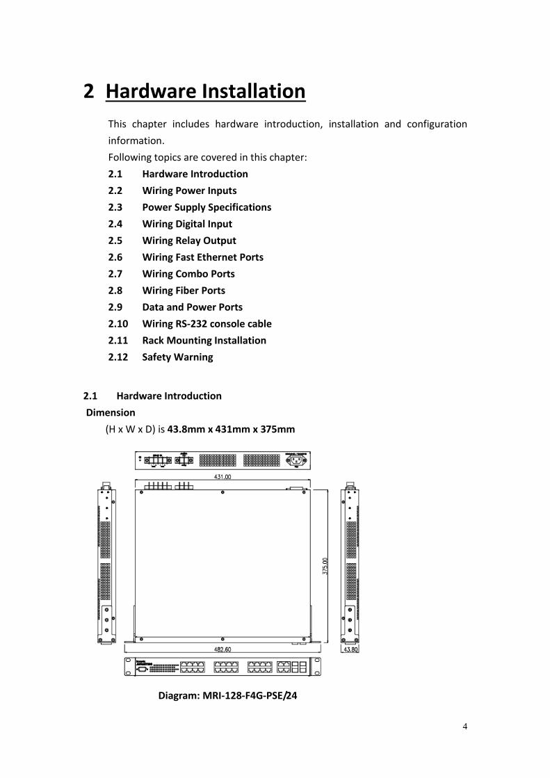
2.1 Hardware Introduction
Dimension
(H x W x D) is 43.8mm x 431mm x 375mm
Diagram: MRI-128-F4G-PSE/24
5
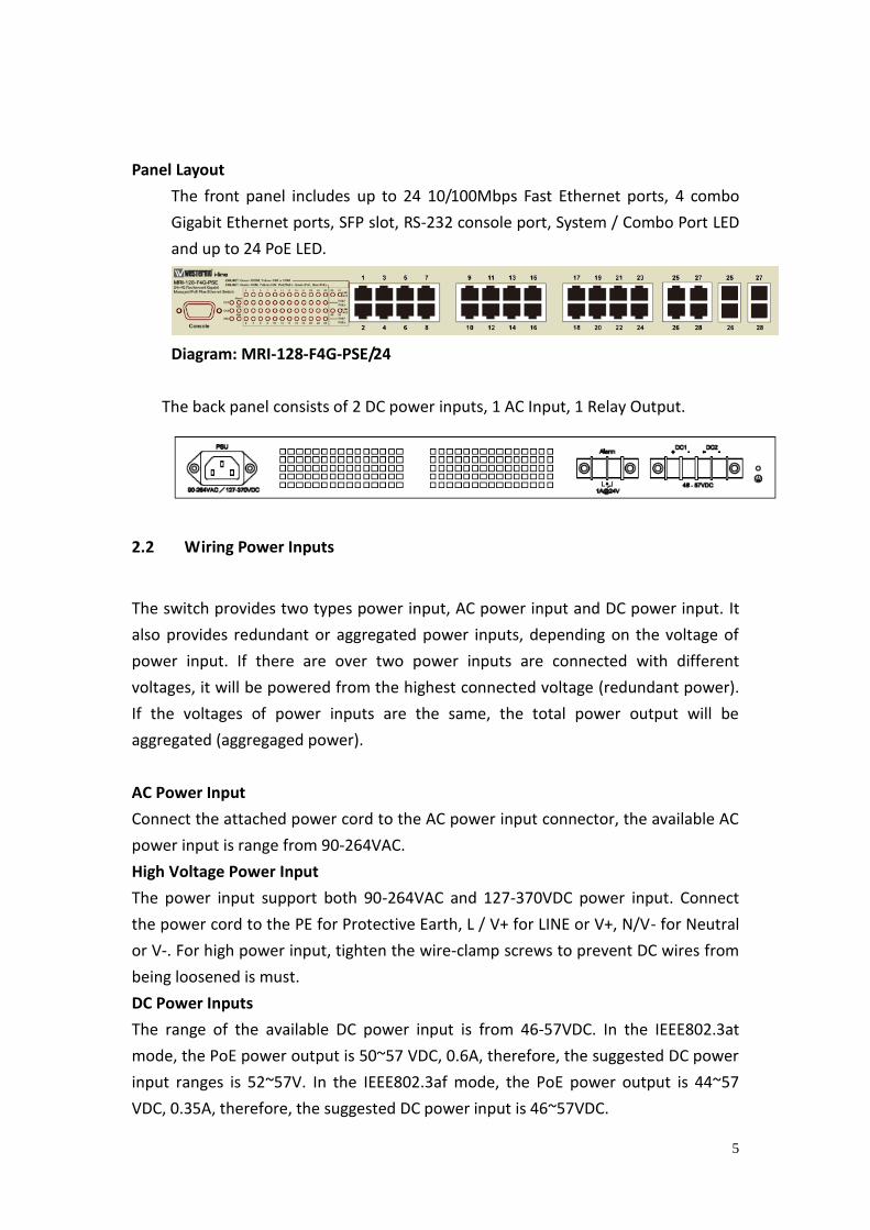
Panel Layout
The front panel includes up to 24 10/100Mbps Fast Ethernet ports, 4 combo
Gigabit Ethernet ports, SFP slot, RS-232 console port, System / Combo Port LED
and up to 24 PoE LED.
Diagram: MRI-128-F4G-PSE/24
The back panel consists of 2 DC power inputs, 1 AC Input, 1 Relay Output.
2.2 Wiring Power Inputs
The switch provides two types power input, AC power input and DC power input. It
also provides redundant or aggregated power inputs, depending on the voltage of
power input. If there are over two power inputs are connected with different
voltages, it will be powered from the highest connected voltage (redundant power).
If the voltages of power inputs are the same, the total power output will be
aggregated (aggregaged power).
AC Power Input
Connect the attached power cord to the AC power input connector, the available AC
power input is range from 90-264VAC.
High Voltage Power Input
The power input support both 90-264VAC and 127-370VDC power input. Connect
the power cord to the PE for Protective Earth, L / V+ for LINE or V+, N/V- for Neutral
or V-. For high power input, tighten the wire-clamp screws to prevent DC wires from
being loosened is must.
DC Power Inputs
The range of the available DC power input is from 46-57VDC. In the IEEE802.3at
mode, the PoE power output is 50~57 VDC, 0.6A, therefore, the suggested DC power
input ranges is 52~57V. In the IEEE802.3af mode, the PoE power output is 44~57
VDC, 0.35A, therefore, the suggested DC power input is 46~57VDC.
6
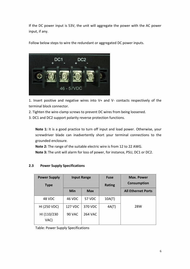
If the DC power input is 53V, the unit will aggregate the power with the AC power
input, if any.
Follow below steps to wire the redundant or aggregated DC power inputs.
1. Insert positive and negative wires into V+ and V- contacts respectively of the
terminal block connector.
2. Tighten the wire-clamp screws to prevent DC wires from being loosened.
3. DC1 and DC2 support polarity reverse protection functions.
Note 1: It is a good practice to turn off input and load power. Otherwise, your
screwdriver blade can inadvertently short your terminal connections to the
grounded enclosure.
Note 2: The range of the suitable electric wire is from 12 to 22 AWG.
Note 3: The unit will alarm for loss of power, for instance, PSU, DC1 or DC2.
2.3 Power Supply Specifications
Power Supply
Type
Input Range Fuse
Rating
Max. Power
Consumption
Min Max All Ethernet Ports
48 VDC 46 VDC 57 VDC 10A(T)
28W HI (250 VDC)
HI (110/230
VAC)
127 VDC
90 VAC
370 VDC
264 VAC
4A(T)
Table: Power Supply Specifications
7
MRI-128-F4G-P24
Power
Supply
Type
Input Range Fuse
Rating
Power Consumption
Min Max Worst
Case
Max
48 VDC 46 VDC 57 VDC 1.5A(F) 369.6W 369.6W
53 VDC 52 VDC 57 VDC 1.5A(F) 568W 720W
Table: PoE/PoE Plus Power Supply Specifications
Note 1: (F) Denotes fast-acting fuse, (T) denotes time-delay fuse
Note 2: Power consumption varies based on configuration. 10/100Tx ports
consume roughly 1W less than fiber optic ports
Note 3: For continued protection against risk of fire, replace only with same
type and rating of fuse.
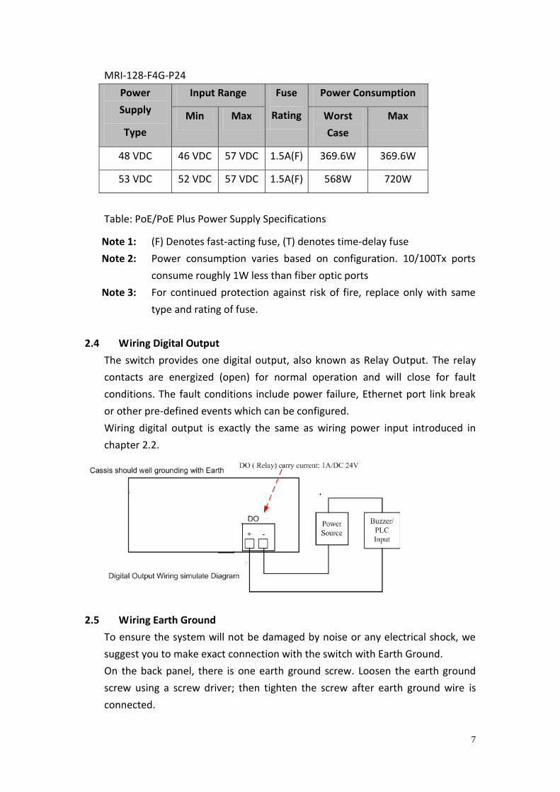
2.4 Wiring Digital Output
The switch provides one digital output, also known as Relay Output. The relay
contacts are energized (open) for normal operation and will close for fault
conditions. The fault conditions include power failure, Ethernet port link break
or other pre-defined events which can be configured.
Wiring digital output is exactly the same as wiring power input introduced in
chapter 2.2.
2.5 Wiring Earth Ground
To ensure the system will not be damaged by noise or any electrical shock, we
suggest you to make exact connection with the switch with Earth Ground.
On the back panel, there is one earth ground screw. Loosen the earth ground
screw using a screw driver; then tighten the screw after earth ground wire is
connected.
8
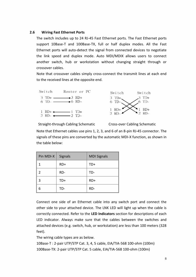
2.6 Wiring Fast Ethernet Ports
The switch includes up to 24 RJ-45 Fast Ethernet ports. The Fast Ethernet ports
support 10Base-T and 100Base-TX, full or half duplex modes. All the Fast
Ethernet ports will auto-detect the signal from connected devices to negotiate
the link speed and duplex mode. Auto MDI/MDIX allows users to connect
another switch, hub or workstation without changing straight through or
crossover cables.
Note that crossover cables simply cross-connect the transmit lines at each end
to the received lines at the opposite end.
Straight-through Cabling Schematic Cross-over Cabling Schematic
Note that Ethernet cables use pins 1, 2, 3, and 6 of an 8-pin RJ-45 connector. The
signals of these pins are converted by the automatic MDI-X function, as shown in
the table below:
Pin MDI-X Signals MDI Signals
1 RD+ TD+
2 RD- TD-
3 TD+ RD+
6 TD- RD-
Connect one side of an Ethernet cable into any switch port and connect the
other side to your attached device. The LNK LED will light up when the cable is
correctly connected. Refer to the LED Indicators section for descriptions of each
LED indicator. Always make sure that the cables between the switches and
attached devices (e.g. switch, hub, or workstation) are less than 100 meters (328
feet).
The wiring cable types are as below.
10Base-T : 2-pair UTP/STP Cat. 3, 4, 5 cable, EIA/TIA-568 100-ohm (100m)
100Base-TX: 2-pair UTP/STP Cat. 5 cable, EIA/TIA-568 100-ohm (100m)
9
1000Base-TX: 4-pair UTP/STP Cat. 5e cable, EIA/TIA-568 100-ohm (100m)
IEEE 802.3af : 4-pair UTP/STP Cat. 5 cable, EIA/TIA-568 100-ohm (100m)
IEEE 802.3at : 4-pair UTP/STP Cat. 5e / 6 cable, EIA/TIA-568 100-ohm (100m)
2.7 Wiring Combo Ports
The switch includes 4 RJ-45 Gigabit Ethernet portswhich supports 10Base-T,
100Base-TX and 1000Base-TX. The switch is also equipped with 4 gigabit SFP
ports combo which supports 1000Base-SX/LX and is according the standard MINI
GBIC SFP transceiver.
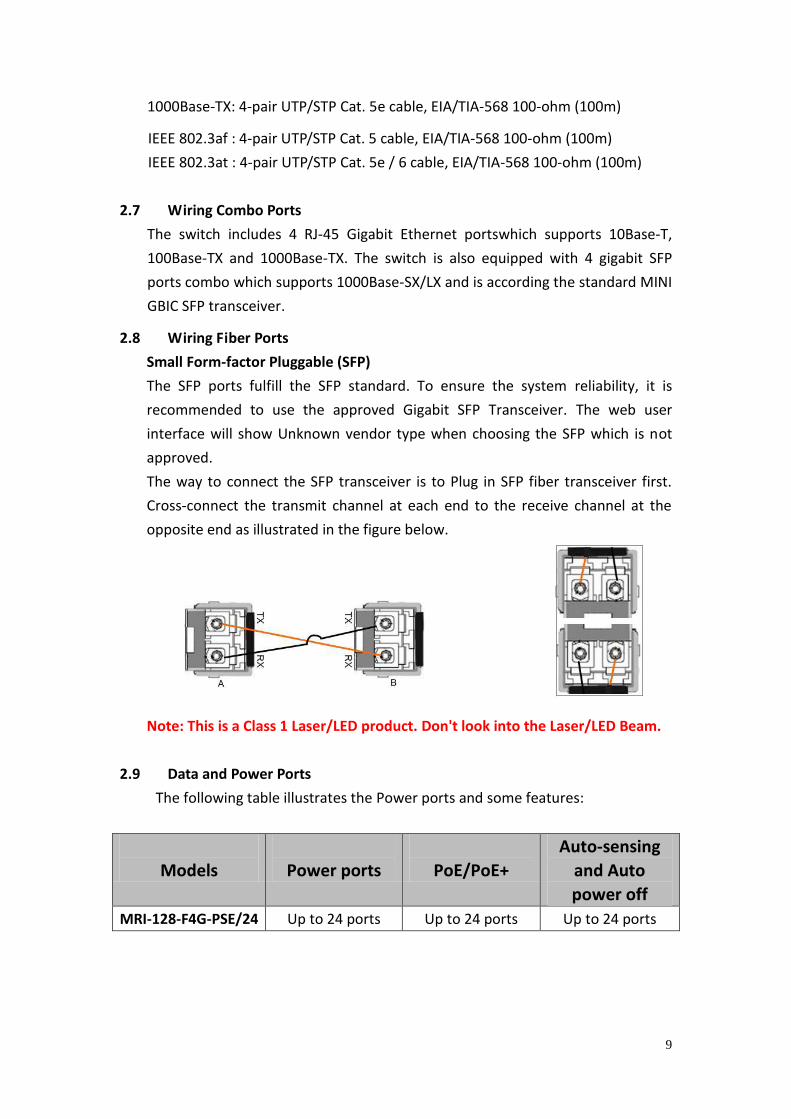
2.8 Wiring Fiber Ports
Small Form-factor Pluggable (SFP)
The SFP ports fulfill the SFP standard. To ensure the system reliability, it is
recommended to use the approved Gigabit SFP Transceiver. The web user
interface will show Unknown vendor type when choosing the SFP which is not
approved.
The way to connect the SFP transceiver is to Plug in SFP fiber transceiver first.
Cross-connect the transmit channel at each end to the receive channel at the
opposite end as illustrated in the figure below.
Note: This is a Class 1 Laser/LED product. Don't look into the Laser/LED Beam.
2.9 Data and Power Ports
The following table illustrates the Power ports and some features:
Models
Power ports
PoE/PoE+
Auto-sensing
and Auto
power off
MRI-128-F4G-PSE/24 Up to 24 ports Up to 24 ports Up to 24 ports
10
The following table shows the RJ45 PoE pin-out assignment.
10/100BaseTx PoE Pin-out
Pin Description
1 RX + and Vport -
2 RX – and Vport -
3 TX + and Vport +
6 TX – and Vport +
4, 5, 7, 8 NC
Table: RJ45 PoE pin-out assignment
2.10 Wiring RS-232 Console Cable
Westermo attaches one RS-232 DB-9 to RJ-45 cable in the box. Connect the DB-9
connector to the COM port of your PC, open Terminal tool and set up serial
settings to 9600, N,8,1. (Baud Rate: 9600 / Parity: None / Data Bit: 8 / Stop Bit: 1)
Then you can access the CLI interface using the console cable.
Note: If you have lost the cable, please contactyour local sales or office or follow
the pin assignment to buy/make a new one. The pin assignment spec is listed in
the appendix.
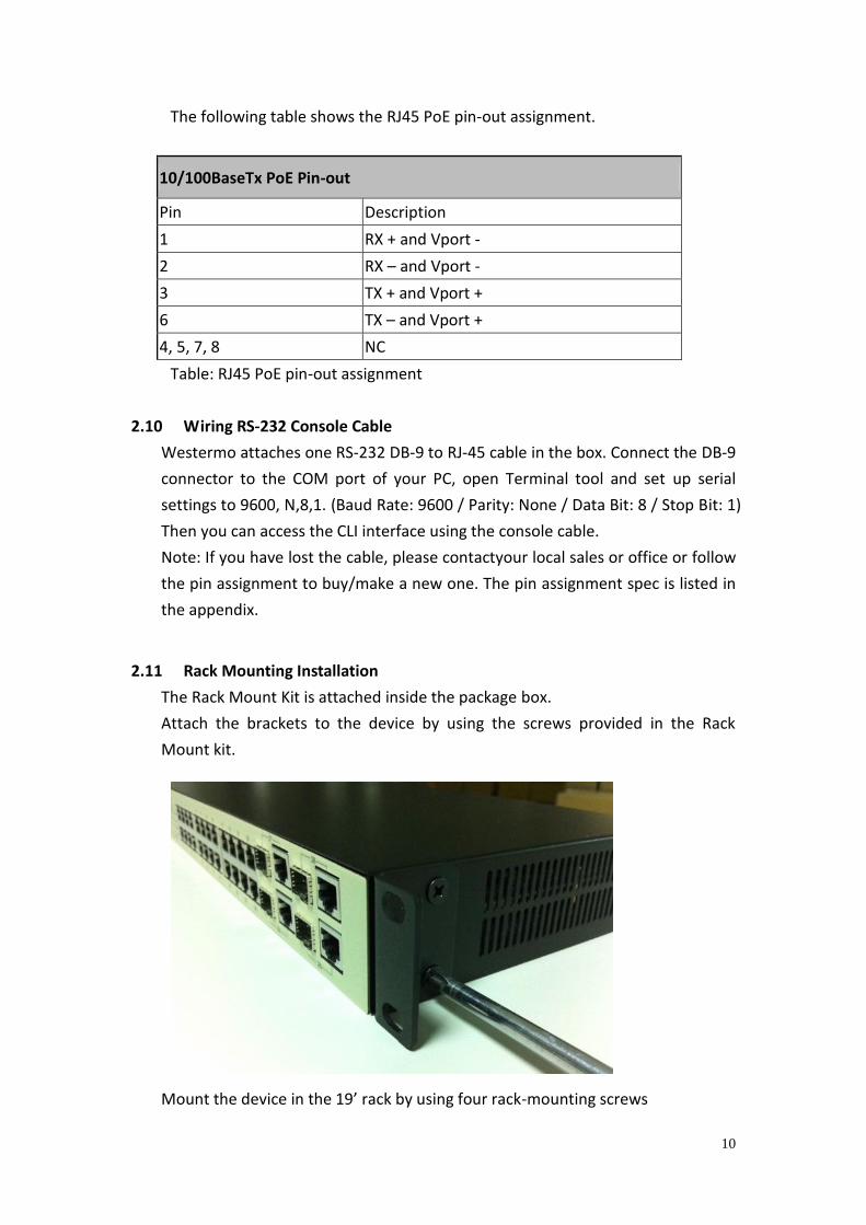
2.11 Rack Mounting Installation
The Rack Mount Kit is attached inside the package box.
Attach the brackets to the device by using the screws provided in the Rack
Mount kit.
Mount the device in the 19’ rack by using four rack-mounting screws
11
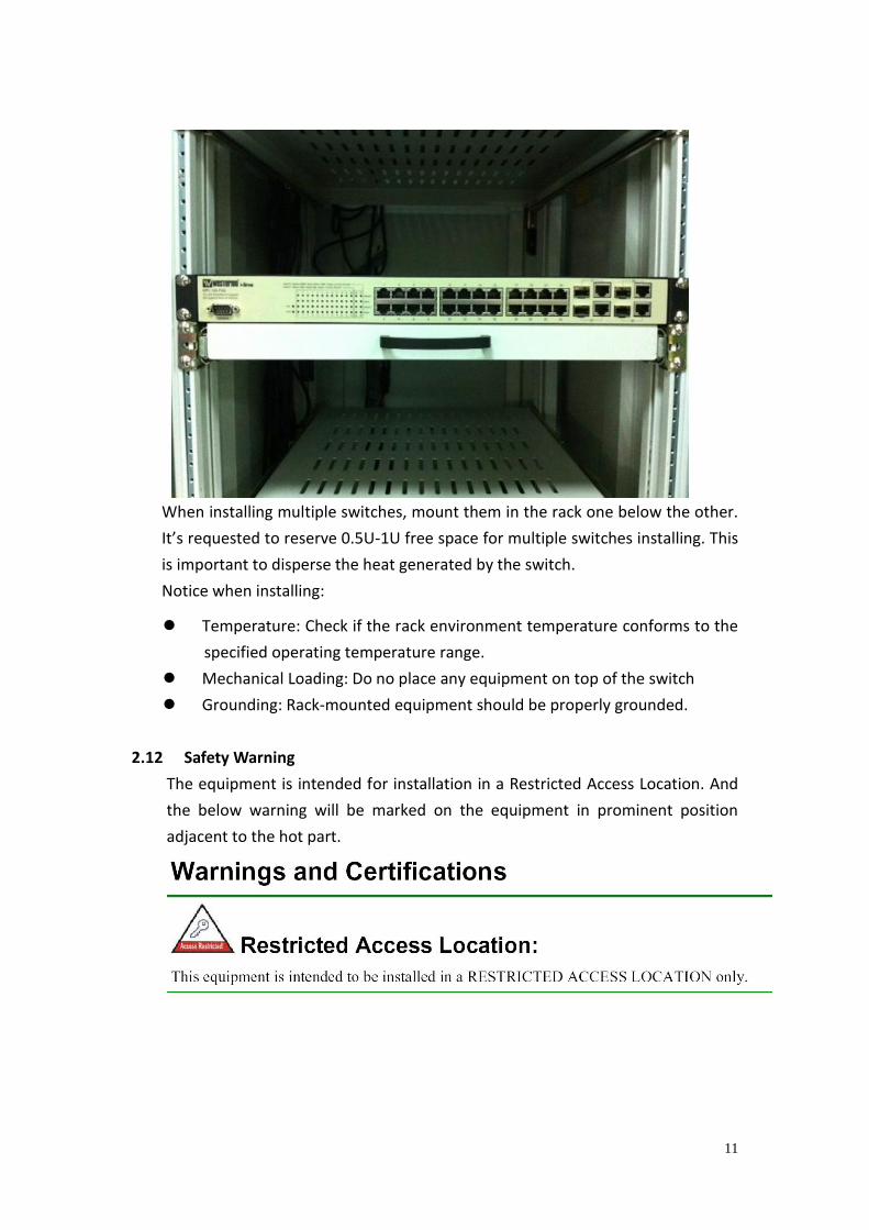
When installing multiple switches, mount them in the rack one below the other.
It’s requested to reserve 0.5U-1U free space for multiple switches installing. This
is important to disperse the heat generated by the switch.
Notice when installing:
Temperature: Check if the rack environment temperature conforms to the
specified operating temperature range.
Mechanical Loading: Do no place any equipment on top of the switch
Grounding: Rack-mounted equipment should be properly grounded.
2.12 Safety Warning
The equipment is intended for installation in a Restricted Access Location. And
the below warning will be marked on the equipment in prominent position
adjacent to the hot part.
12
3 Preparation for Management
The switch provides both in-band and out-band configuration methods. You
can configure the switch via RS232 console cable if you don’t attach your admin
PC to your network, or if you lose network connection to the switch. This is
so-called out-band management. It wouldn’t be affected by network
connectivity. The in-band management means you can remotely manage the
switch via the network. You can choose Telnet or Web-based management.
You just need to know the device’s IP address and you can remotely connect to
its embedded HTTP web pages or Telnet console.Following topics are covered
in this chapter:
3.1 Preparation for Serial Console
3.2 Preparation for Web Interface
3.3 Preparation for Telnet console
3.1 Preparation for Serial Console
In the package, Westermo attached one RS-232 DB-9 console cable. Please
attach RS-232 DB-9 connector to your PC COM port, connect to the Console
port of the the switch. If you lose/lost the cable, please follow the console
cable PIN assignment to find a new one, or contact your closest Westermo
sales office. (Refer to the appendix).
1. Go to Start -> Program -> Accessories -> Communication -> Hyper Terminal
2. Give a name to the new console connection.
3. Choose the COM name
4. Select correct serial settings. The serial settings of The switch are as below:
Baud Rate: 9600 / Parity: None / Data Bit: 8 / Stop Bit: 1
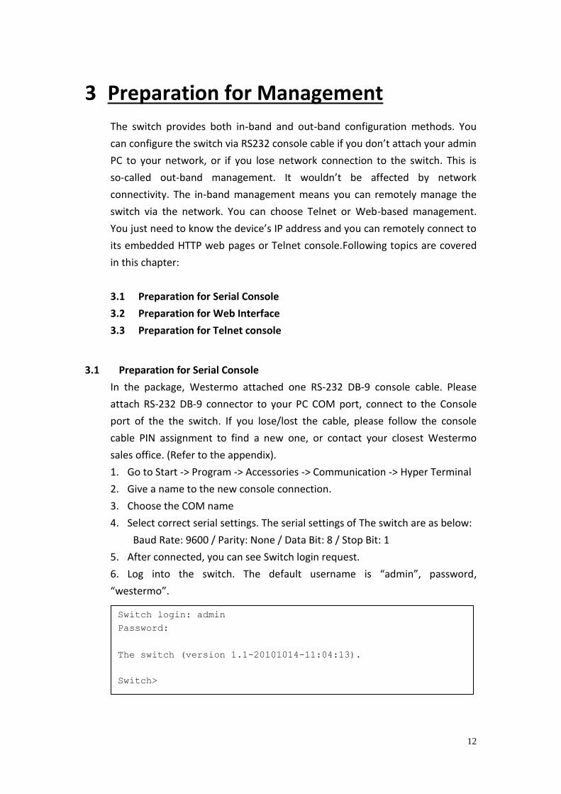
5. After connected, you can see Switch login request.
6. Log into the switch. The default username is “admin”, password,
“westermo”.
Switch login: admin
Password:
The switch (version 1.1-20101014-11:04:13).
Switch>
13
3.2 Preparation for Web Interface
The switch provides HTTP Web Interface and Secured HTTPS Web Interface for
web management.
3.2.1 Web Interface
Web management page is developed by JAVA. It allows you to use a standard
web-browser such as Microsoft Internet Explorer, or Mozilla Firefox, to
configure and/or log from the switch from anywhere on the network.
Before you attempt to use the embedded web interface to manage switch
operation, verify that the switch is properly installed on your network and that
every the PC on this network can access the switch via the web browser.
1. Verify that your network interface card (NIC) is operational, and that your
operating system supports TCP/IP protocol.
2. Wire DC power to the switch and connect your switch to your computer.
3. Make sure that the switch default IP address is 192.168.2.200.
4. Change your computer IP address to 192.168.2.2 or other IP address which
is located in the 192.168.2.x (Network Mask: 255.255.255.0) subnet.
5. Switch to DOS command mode and ping 192.168.2.200 to verify a normal
response time.
Launch the web browser and Login.
6. Launch the web browser (Internet Explorer or Mozilla Firefox) on the PC.
7. Type http://192.168.2.200 (or the IP address of the switch). And then press
Enter.
8. The login screen will appear next.
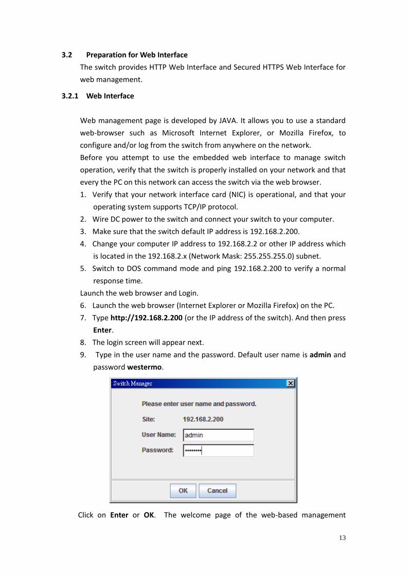
9. Type in the user name and the password. Default user name is admin and
password westermo.
Click on Enter or OK. The welcome page of the web-based management
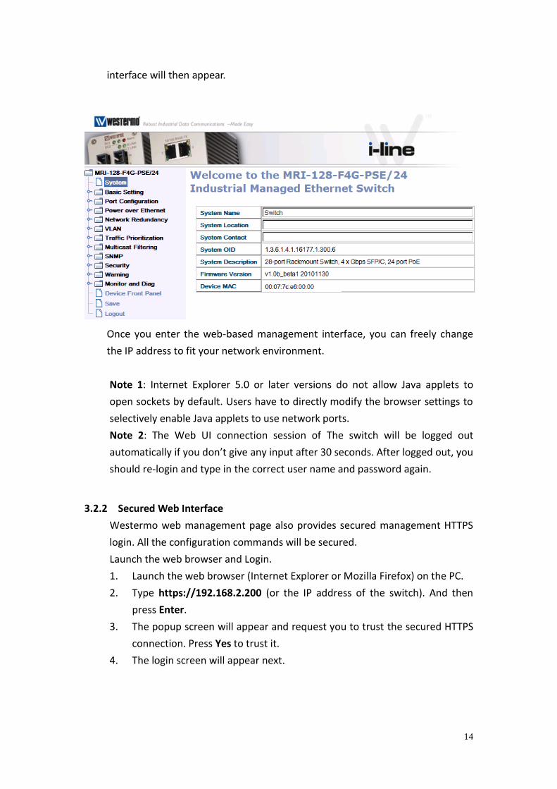
14
interface will then appear.
Once you enter the web-based management interface, you can freely change
the IP address to fit your network environment.
Note 1: Internet Explorer 5.0 or later versions do not allow Java applets to
open sockets by default. Users have to directly modify the browser settings to
selectively enable Java applets to use network ports.
Note 2: The Web UI connection session of The switch will be logged out
automatically if you don’t give any input after 30 seconds. After logged out, you
should re-login and type in the correct user name and password again.
3.2.2 Secured Web Interface
Westermo web management page also provides secured management HTTPS
login. All the configuration commands will be secured.
Launch the web browser and Login.
1. Launch the web browser (Internet Explorer or Mozilla Firefox) on the PC.
2. Type https://192.168.2.200 (or the IP address of the switch). And then
press Enter.
3. The popup screen will appear and request you to trust the secured HTTPS
connection. Press Yes to trust it.
4. The login screen will appear next.
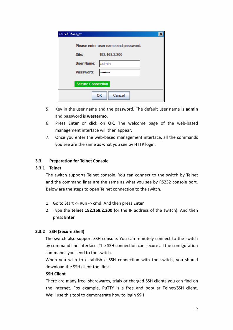
15
5. Key in the user name and the password. The default user name is admin
and password is westermo.
6. Press Enter or click on OK. The welcome page of the web-based
management interface will then appear.
7. Once you enter the web-based management interface, all the commands
you see are the same as what you see by HTTP login.
3.3 Preparation for Telnet Console
3.3.1 Telnet
The switch supports Telnet console. You can connect to the switch by Telnet
and the command lines are the same as what you see by RS232 console port.
Below are the steps to open Telnet connection to the switch.
1. Go to Start -> Run -> cmd. And then press Enter
2. Type the telnet 192.168.2.200 (or the IP address of the switch). And then
press Enter
3.3.2 SSH (Secure Shell)
The switch also support SSH console. You can remotely connect to the switch
by command line interface. The SSH connection can secure all the configuration
commands you send to the switch.
When you wish to establish a SSH connection with the switch, you should
download the SSH client tool first.
SSH Client
There are many free, sharewares, trials or charged SSH clients you can find on
the internet. Fox example, PuTTY is a free and popular Telnet/SSH client.
We’ll use this tool to demonstrate how to login SSH
16
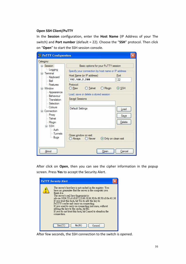
Open SSH Client/PuTTY
In the Session configuration, enter the Host Name (IP Address of your The
switch) and Port number (default = 22). Choose the “SSH” protocol. Then click
on “Open” to start the SSH session console.
After click on Open, then you can see the cipher information in the popup
screen. Press Yes to accept the Security Alert.
After few seconds, the SSH connection to the switch is opened.

17
Type the Login Name and its Password. The default Login Name and Password
are admin / westermo.
All the commands you see in SSH are the same as the CLI commands you see
via RS232 console. The next chapter will introduce in detail how to use
command line to configure the switch.
18
4 Feature Configuration
This chapter explains how to configure the switch software features. There are
four ways to access the switch: Serial console, Telnet/SSH, Web browser and
SNMP.
Following topics are covered in this chapter:.
4.1 Command Line Interface (CLI) Introduction
4.2 Basic Setting
4.3 Port Configuration
4.4 Power over Ethernet
4.5 Network Redundancy
4.6 VLAN
4.7 Traffic Prioritization
4.8 Multicast Filtering
4.9 SNMP
4.10 Security
4.11 Warning
4.12 Monitor and Diag
4.13 Device Front Panel
4.14 Save
4.15 Logout
4.1 Command Line Interface Introduction The Command Line Interface (CLI) is one of the user interfaces to the switch’s
embedded software system. You can view the system information, show the
status, configure the switch and receive a response back from the system by
typing in a command.
There are different command modes andeach mode has its own access ability,
available command lines and uses different command lines to enter and exit.
These modes are User EXEC, Privileged EXEC, Global Configuration and
(Port/VLAN) Interface Configuration modes.
User EXEC mode: As long as you log into the switch by CLI you are in the User
EXEC mode. You can ping, telnet remote device, and show some basic
information.
Type enable to enter the next mode, exit to logout. ? to see the command list
19
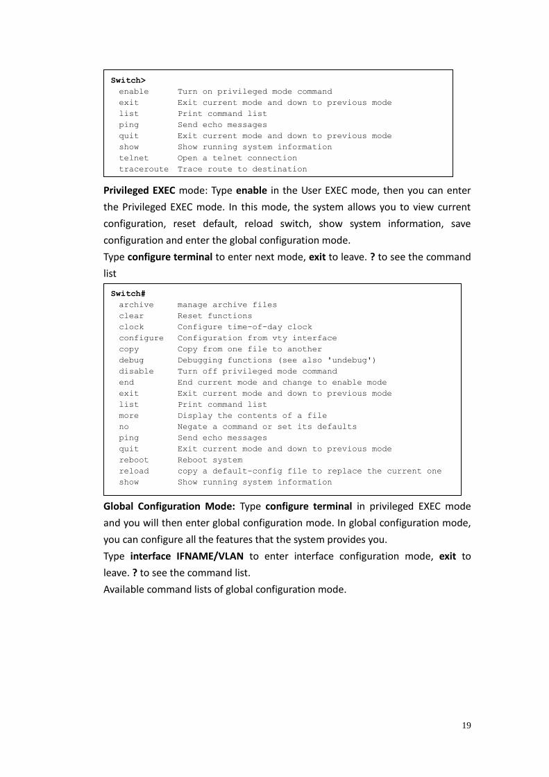
Privileged EXEC mode: Type enable in the User EXEC mode, then you can enter
the Privileged EXEC mode. In this mode, the system allows you to view current
configuration, reset default, reload switch, show system information, save
configuration and enter the global configuration mode.
Type configure terminal to enter next mode, exit to leave. ? to see the command
list
Global Configuration Mode: Type configure terminal in privileged EXEC mode
and you will then enter global configuration mode. In global configuration mode,
you can configure all the features that the system provides you.
Type interface IFNAME/VLAN to enter interface configuration mode, exit to
leave. ? to see the command list.
Available command lists of global configuration mode.
Switch>
enable Turn on privileged mode command
exit Exit current mode and down to previous mode
list Print command list
ping Send echo messages
quit Exit current mode and down to previous mode
show Show running system information
telnet Open a telnet connection
traceroute Trace route to destination
Switch#
archive manage archive files
clear Reset functions
clock Configure time-of-day clock
configure Configuration from vty interface
copy Copy from one file to another
debug Debugging functions (see also 'undebug')
disable Turn off privileged mode command
end End current mode and change to enable mode
exit Exit current mode and down to previous mode
list Print command list
more Display the contents of a file
no Negate a command or set its defaults
ping Send echo messages
quit Exit current mode and down to previous mode
reboot Reboot system
reload copy a default-config file to replace the current one
show Show running system information
20
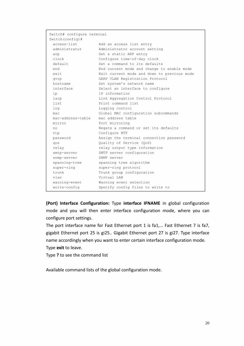
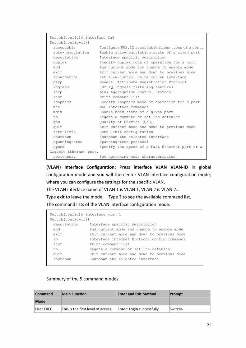
(Port) Interface Configuration: Type interface IFNAME in global configuration
mode and you will then enter interface configuration mode, where you can
configure port settings.
The port interface name for Fast Ethernet port 1 is fa1,… Fast Ethernet 7 is fa7,
gigabit Ethernet port 25 is gi25.. Gigabit Ethernet port 27 is gi27. Type interface
name accordingly when you want to enter certain interface configuration mode.
Type exit to leave.
Type ? to see the command list
Available command lists of the global configuration mode.
Switch# configure terminal
Switch(config)#
access-list Add an access list entry
administrator Administrator account setting
arp Set a static ARP entry
clock Configure time-of-day clock
default Set a command to its defaults
end End current mode and change to enable mode
exit Exit current mode and down to previous mode
gvrp GARP VLAN Registration Protocol
hostname Set system's network name
interface Select an interface to configure
ip IP information
lacp Link Aggregation Control Protocol
list Print command list
log Logging control
mac Global MAC configuration subcommands
mac-address-table mac address table
mirror Port mirroring
no Negate a command or set its defaults
ntp Configure NTP
password Assign the terminal connection password
qos Quality of Service (QoS)
relay relay output type information
smtp-server SMTP server configuration
snmp-server SNMP server
spanning-tree spanning tree algorithm
super-ring super-ring protocol
trunk Trunk group configuration
vlan Virtual LAN
warning-event Warning event selection
write-config Specify config files to write to
21
(VLAN) Interface Configuration: Press interface VLAN VLAN-ID in global
configuration mode and you will then enter VLAN interface configuration mode,
where you can configure the settings for the specific VLAN.
The VLAN interface name of VLAN 1 is VLAN 1, VLAN 2 is VLAN 2…
Type exit to leave the mode. Type ? to see the available command list.
The command lists of the VLAN interface configuration mode.
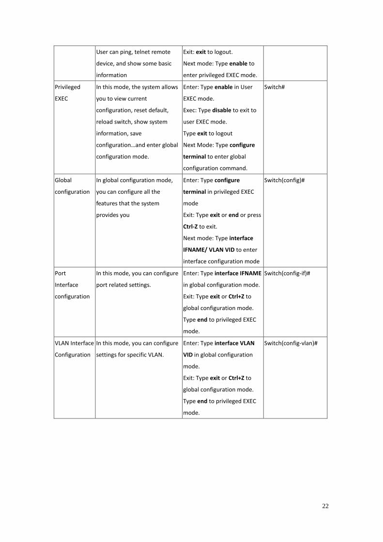
Summary of the 5 command modes.
Command
Mode
Main Function Enter and Exit Method Prompt
User EXEC This is the first level of access. Enter: Login successfully Switch>
Switch(config)# interface fa1
Switch(config-if)#
acceptable Configure 802.1Q acceptable frame types of a port.
auto-negotiation Enable auto-negotiation state of a given port
description Interface specific description
duplex Specify duplex mode of operation for a port
end End current mode and change to enable mode
exit Exit current mode and down to previous mode
flowcontrol Set flow-control value for an interface
garp General Attribute Registration Protocol
ingress 802.1Q ingress filtering features
lacp Link Aggregation Control Protocol
list Print command list
loopback Specify loopback mode of operation for a port
mac MAC interface commands
mdix Enable mdix state of a given port
no Negate a command or set its defaults
qos Quality of Service (QoS)
quit Exit current mode and down to previous mode
rate-limit Rate limit configuration
shutdown Shutdown the selected interface
spanning-tree spanning-tree protocol
speed Specify the speed of a Fast Ethernet port or a
Gigabit Ethernet port.
switchport Set switching mode characteristics
Switch(config)# interface vlan 1
Switch(config-if)#
description Interface specific description
end End current mode and change to enable mode
exit Exit current mode and down to previous mode
ip Interface Internet Protocol config commands
list Print command list
no Negate a command or set its defaults
quit Exit current mode and down to previous mode
shutdown Shutdown the selected interface
22
User can ping, telnet remote
device, and show some basic
information
Exit: exit to logout.
Next mode: Type enable to
enter privileged EXEC mode.
Privileged
EXEC
In this mode, the system allows
you to view current
configuration, reset default,
reload switch, show system
information, save
configuration…and enter global
configuration mode.
Enter: Type enable in User
EXEC mode.
Exec: Type disable to exit to
user EXEC mode.
Type exit to logout
Next Mode: Type configure
terminal to enter global
configuration command.
Switch#
Global
configuration
In global configuration mode,
you can configure all the
features that the system
provides you
Enter: Type configure
terminal in privileged EXEC
mode
Exit: Type exit or end or press
Ctrl-Z to exit.
Next mode: Type interface
IFNAME/ VLAN VID to enter
interface configuration mode
Switch(config)#
Port
Interface
configuration
In this mode, you can configure
port related settings.
Enter: Type interface IFNAME
in global configuration mode.
Exit: Type exit or Ctrl+Z to
global configuration mode.
Type end to privileged EXEC
mode.
Switch(config-if)#
VLAN Interface
Configuration
In this mode, you can configure
settings for specific VLAN.
Enter: Type interface VLAN
VID in global configuration
mode.
Exit: Type exit or Ctrl+Z to
global configuration mode.
Type end to privileged EXEC
mode.
Switch(config-vlan)#
23
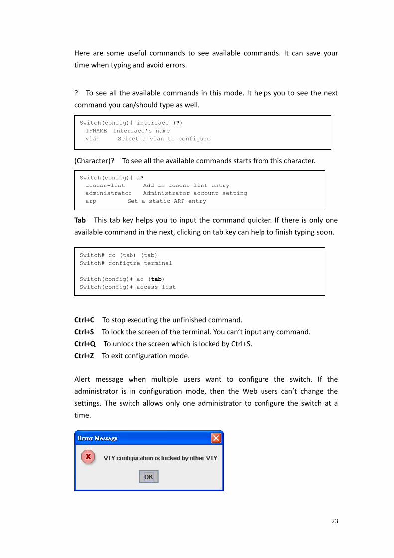
Here are some useful commands to see available commands. It can save your
time when typing and avoid errors.
? To see all the available commands in this mode. It helps you to see the next
command you can/should type as well.
(Character)? To see all the available commands starts from this character.
Tab This tab key helps you to input the command quicker. If there is only one
available command in the next, clicking on tab key can help to finish typing soon.
Ctrl+C To stop executing the unfinished command.
Ctrl+S To lock the screen of the terminal. You can’t input any command.
Ctrl+Q To unlock the screen which is locked by Ctrl+S.
Ctrl+Z To exit configuration mode.
Alert message when multiple users want to configure the switch. If the
administrator is in configuration mode, then the Web users can’t change the
settings. The switch allows only one administrator to configure the switch at a
time.
Switch(config)# interface (?)
IFNAME Interface's name
vlan Select a vlan to configure
Switch(config)# a?
access-list Add an access list entry
administrator Administrator account setting
arp Set a static ARP entry
Switch# co (tab) (tab)
Switch# configure terminal
Switch(config)# ac (tab)
Switch(config)# access-list
24
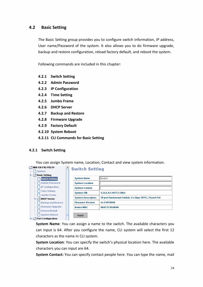
4.2 Basic Setting
The Basic Setting group provides you to configure switch information, IP address,
User name/Password of the system. It also allows you to do firmware upgrade,
backup and restore configuration, reload factory default, and reboot the system.
Following commands are included in this chapter:
4.2.1 Switch Setting
4.2.2 Admin Password
4.2.3 IP Configuration
4.2.4 Time Setting
4.2.5 Jumbo Frame
4.2.6 DHCP Server
4.2.7 Backup and Restore
4.2.8 Firmware Upgrade
4.2.9 Factory Default
4.2.10 System Reboot
4.2.11 CLI Commands for Basic Setting
4.2.1 Switch Setting
You can assign System name, Location, Contact and view system information.
System Name: You can assign a name to the switch. The available characters you
can input is 64. After you configure the name, CLI system will select the first 12
characters as the name in CLI system.
System Location: You can specify the switch’s physical location here. The available
characters you can input are 64.
System Contact: You can specify contact people here. You can type the name, mail
25
address or other information of the administrator. The available characters you
can input are 64.
System OID: The SNMP object ID of the switch. You can follow the path to find its
private MIB in MIB browser. (Note: When you attempt to view private MIB, you
should compile private MIB files into your MIB browser first.)
System Description: The name of this product.
Firmware Version: Display the firmware version installed in this device.
MAC Address: Display unique hardware address (MAC address) assigned by the
manufacturer.
Once you finish the configuration, click on Apply to apply your settings.
Note: Always remember to select Save to save your settings. Otherwise, the
settings you made will be lost when the switch is powered off.
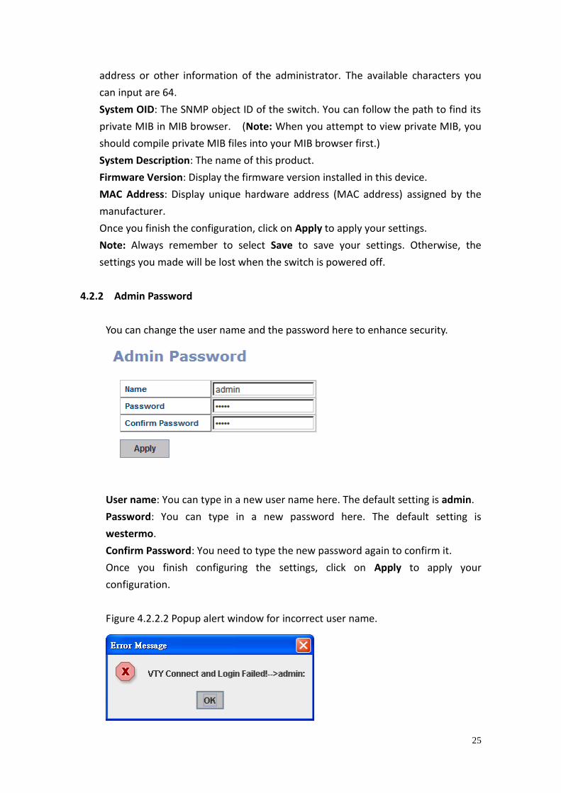
4.2.2 Admin Password
You can change the user name and the password here to enhance security.
User name: You can type in a new user name here. The default setting is admin.
Password: You can type in a new password here. The default setting is
westermo.
Confirm Password: You need to type the new password again to confirm it.
Once you finish configuring the settings, click on Apply to apply your
configuration.
Figure 4.2.2.2 Popup alert window for incorrect user name.
26
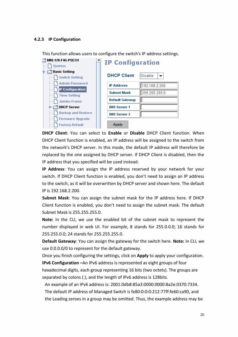
4.2.3 IP Configuration
This function allows users to configure the switch’s IP address settings.
DHCP Client: You can select to Enable or Disable DHCP Client function. When
DHCP Client function is enabled, an IP address will be assigned to the switch from
the network’s DHCP server. In this mode, the default IP address will therefore be
replaced by the one assigned by DHCP server. If DHCP Client is disabled, then the
IP address that you specified will be used instead.
IP Address: You can assign the IP address reserved by your network for your
switch. If DHCP Client function is enabled, you don’t need to assign an IP address
to the switch, as it will be overwritten by DHCP server and shown here. The default
IP is 192.168.2.200.
Subnet Mask: You can assign the subnet mask for the IP address here. If DHCP
Client function is enabled, you don’t need to assign the subnet mask. The default
Subnet Mask is 255.255.255.0.
Note: In the CLI, we use the enabled bit of the subnet mask to represent the
number displayed in web UI. For example, 8 stands for 255.0.0.0; 16 stands for
255.255.0.0; 24 stands for 255.255.255.0.
Default Gateway: You can assign the gateway for the switch here. Note: In CLI, we
use 0.0.0.0/0 to represent for the default gateway.
Once you finish configuring the settings, click on Apply to apply your configuration.
IPv6 Configuration –An IPv6 address is represented as eight groups of four
hexadecimal digits, each group representing 16 bits (two octets). The groups are
separated by colons (:), and the length of IPv6 address is 128bits.
An example of an IPv6 address is: 2001:0db8:85a3:0000:0000:8a2e:0370:7334.
The default IP address of Managed Switch is fe80:0:0:0:212:77ff:fe60:ca90, and
the Leading zeroes in a group may be omitted. Thus, the example address may be
27
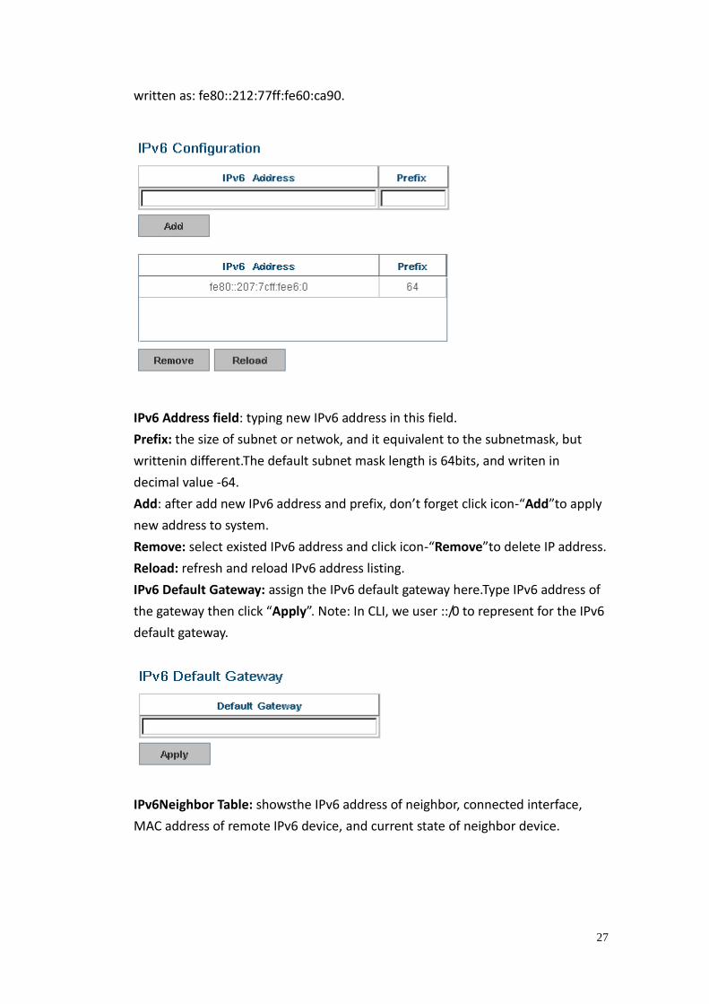
written as: fe80::212:77ff:fe60:ca90.
IPv6 Address field: typing new IPv6 address in this field.
Prefix: the size of subnet or netwok, and it equivalent to the subnetmask, but
writtenin different.The default subnet mask length is 64bits, and writen in
decimal value -64.
Add: after add new IPv6 address and prefix, don’t forget click icon-“Add”to apply
new address to system.
Remove: select existed IPv6 address and click icon-“Remove”to delete IP address.
Reload: refresh and reload IPv6 address listing.
IPv6 Default Gateway: assign the IPv6 default gateway here.Type IPv6 address of
the gateway then click “Apply”. Note: In CLI, we user ::/0 to represent for the IPv6
default gateway.
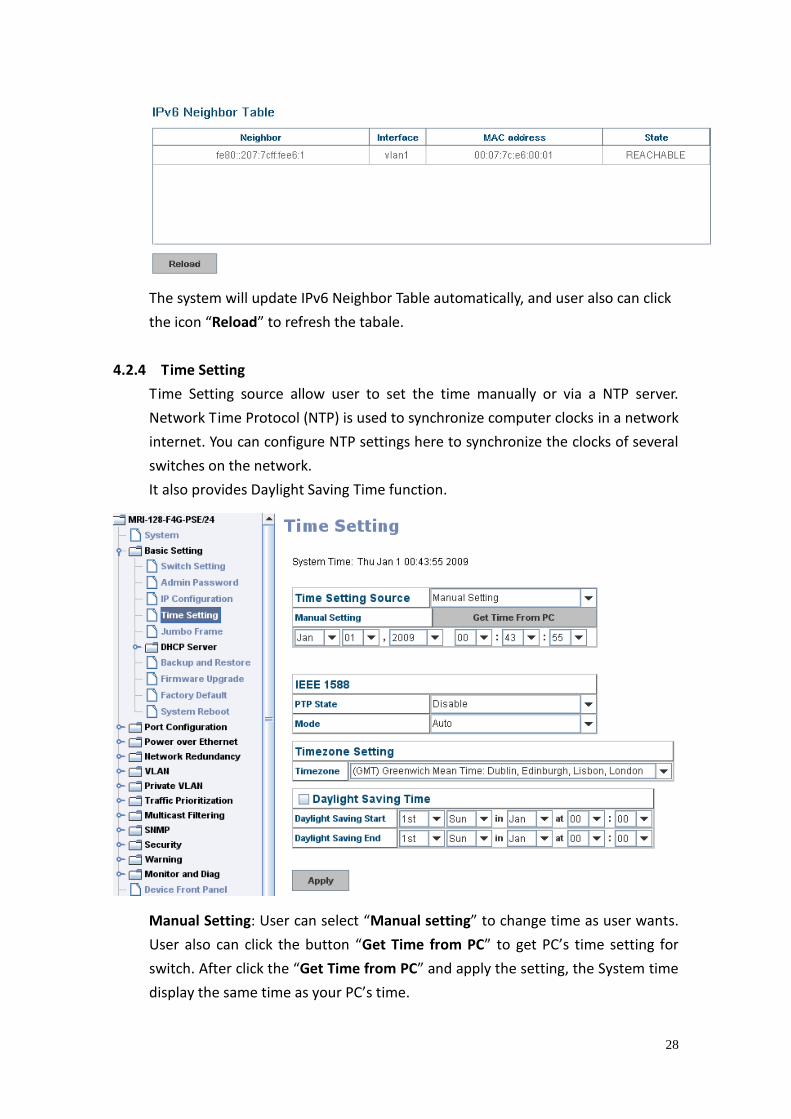
IPv6Neighbor Table: showsthe IPv6 address of neighbor, connected interface,
MAC address of remote IPv6 device, and current state of neighbor device.
28
The system will update IPv6 Neighbor Table automatically, and user also can click
the icon “Reload” to refresh the tabale.
4.2.4 Time Setting
Time Setting source allow user to set the time manually or via a NTP server.
Network Time Protocol (NTP) is used to synchronize computer clocks in a network
internet. You can configure NTP settings here to synchronize the clocks of several
switches on the network.
It also provides Daylight Saving Time function.
Manual Setting: User can select “Manual setting” to change time as user wants.
User also can click the button “Get Time from PC” to get PC’s time setting for
switch. After click the “Get Time from PC” and apply the setting, the System time
display the same time as your PC’s time.
29
NTP client: Set Time Setting Source to NTP client to enable the NTP client service.
NTP client will be automatically enabled if you change Time source to NTP Client.
The system will send requests to acquire current time from the configured NTP
server.
IEEE 1588: With the Precision Time Protocol IEEE 1588
is a high-precision time protocol for synchronization used in control system on a
network.
To enable IEEE 1588, select Enable in PTP Status and choose Auto, Master or
Slave Mode. After time synchronized, the system time will display the correct
time of the PTP server.
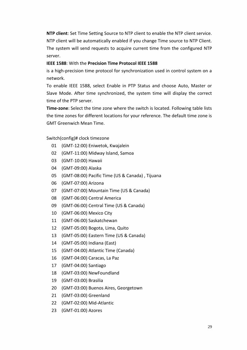
Time-zone: Select the time zone where the switch is located. Following table lists
the time zones for different locations for your reference. The default time zone is
GMT Greenwich Mean Time.
Switch(config)# clock timezone
01 (GMT-12:00) Eniwetok, Kwajalein
02 (GMT-11:00) Midway Island, Samoa
03 (GMT-10:00) Hawaii
04 (GMT-09:00) Alaska
05 (GMT-08:00) Pacific Time (US & Canada) , Tijuana
06 (GMT-07:00) Arizona
07 (GMT-07:00) Mountain Time (US & Canada)
08 (GMT-06:00) Central America
09 (GMT-06:00) Central Time (US & Canada)
10 (GMT-06:00) Mexico City
11 (GMT-06:00) Saskatchewan
12 (GMT-05:00) Bogota, Lima, Quito
13 (GMT-05:00) Eastern Time (US & Canada)
14 (GMT-05:00) Indiana (East)
15 (GMT-04:00) Atlantic Time (Canada)
16 (GMT-04:00) Caracas, La Paz
17 (GMT-04:00) Santiago
18 (GMT-03:00) NewFoundland
19 (GMT-03:00) Brasilia
20 (GMT-03:00) Buenos Aires, Georgetown
21 (GMT-03:00) Greenland
22 (GMT-02:00) Mid-Atlantic
23 (GMT-01:00) Azores
30
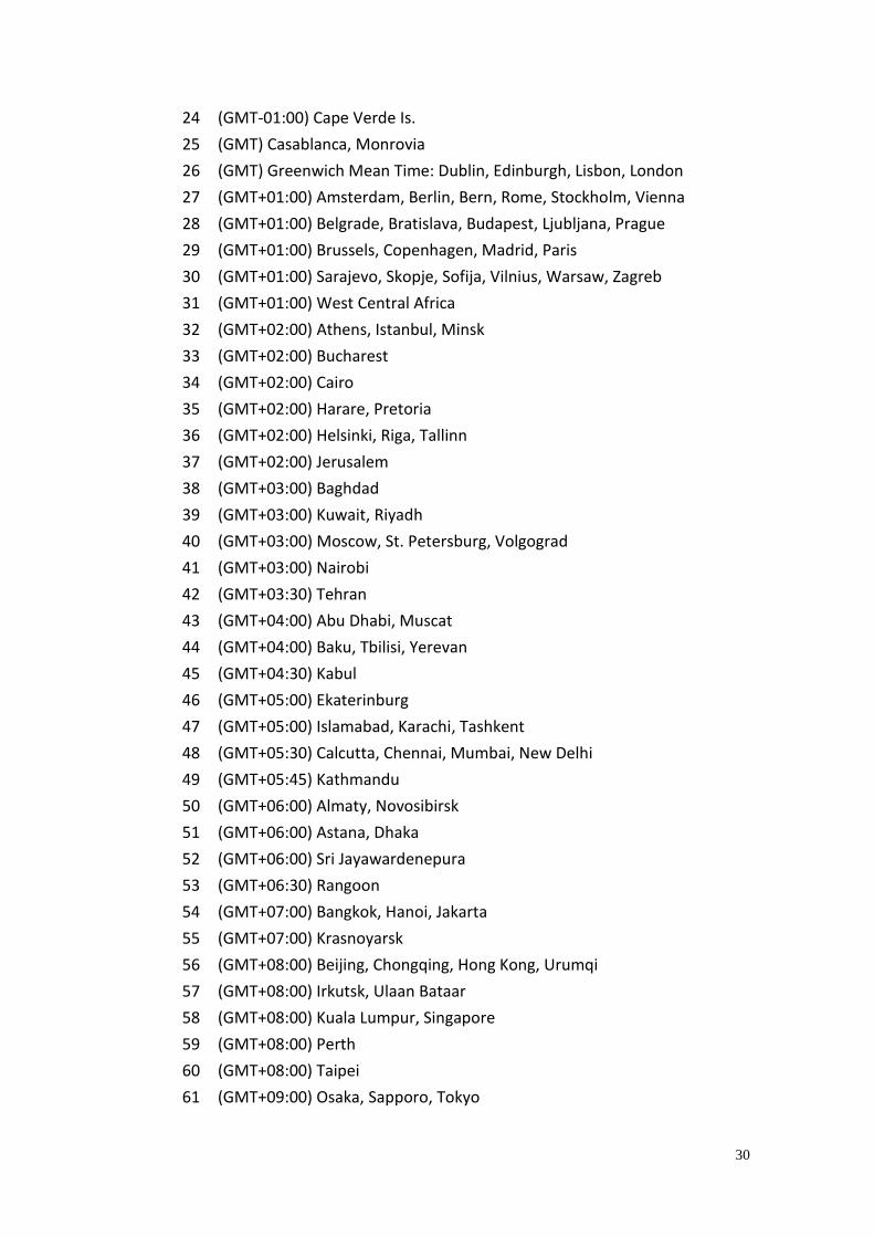
24 (GMT-01:00) Cape Verde Is.
25 (GMT) Casablanca, Monrovia
26 (GMT) Greenwich Mean Time: Dublin, Edinburgh, Lisbon, London
27 (GMT+01:00) Amsterdam, Berlin, Bern, Rome, Stockholm, Vienna
28 (GMT+01:00) Belgrade, Bratislava, Budapest, Ljubljana, Prague
29 (GMT+01:00) Brussels, Copenhagen, Madrid, Paris
30 (GMT+01:00) Sarajevo, Skopje, Sofija, Vilnius, Warsaw, Zagreb
31 (GMT+01:00) West Central Africa
32 (GMT+02:00) Athens, Istanbul, Minsk
33 (GMT+02:00) Bucharest
34 (GMT+02:00) Cairo
35 (GMT+02:00) Harare, Pretoria
36 (GMT+02:00) Helsinki, Riga, Tallinn
37 (GMT+02:00) Jerusalem
38 (GMT+03:00) Baghdad
39 (GMT+03:00) Kuwait, Riyadh
40 (GMT+03:00) Moscow, St. Petersburg, Volgograd
41 (GMT+03:00) Nairobi
42 (GMT+03:30) Tehran
43 (GMT+04:00) Abu Dhabi, Muscat
44 (GMT+04:00) Baku, Tbilisi, Yerevan
45 (GMT+04:30) Kabul
46 (GMT+05:00) Ekaterinburg
47 (GMT+05:00) Islamabad, Karachi, Tashkent
48 (GMT+05:30) Calcutta, Chennai, Mumbai, New Delhi
49 (GMT+05:45) Kathmandu
50 (GMT+06:00) Almaty, Novosibirsk
51 (GMT+06:00) Astana, Dhaka
52 (GMT+06:00) Sri Jayawardenepura
53 (GMT+06:30) Rangoon
54 (GMT+07:00) Bangkok, Hanoi, Jakarta
55 (GMT+07:00) Krasnoyarsk
56 (GMT+08:00) Beijing, Chongqing, Hong Kong, Urumqi
57 (GMT+08:00) Irkutsk, Ulaan Bataar
58 (GMT+08:00) Kuala Lumpur, Singapore
59 (GMT+08:00) Perth
60 (GMT+08:00) Taipei
61 (GMT+09:00) Osaka, Sapporo, Tokyo
31
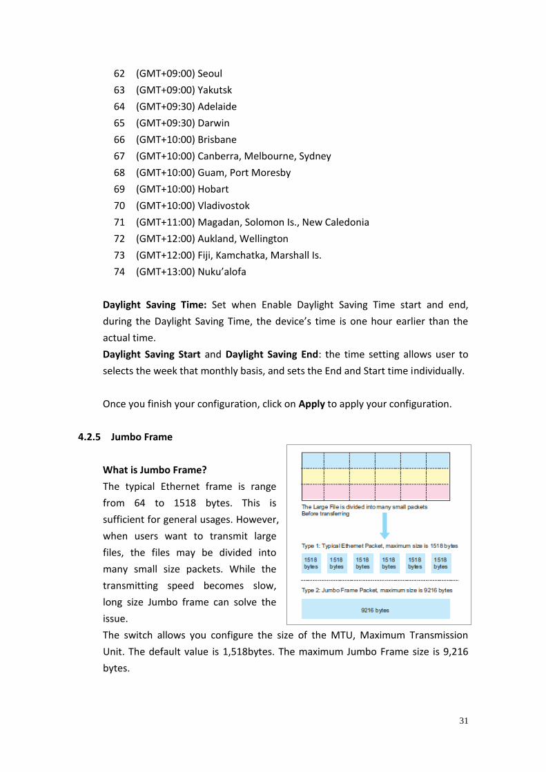
62 (GMT+09:00) Seoul
63 (GMT+09:00) Yakutsk
64 (GMT+09:30) Adelaide
65 (GMT+09:30) Darwin
66 (GMT+10:00) Brisbane
67 (GMT+10:00) Canberra, Melbourne, Sydney
68 (GMT+10:00) Guam, Port Moresby
69 (GMT+10:00) Hobart
70 (GMT+10:00) Vladivostok
71 (GMT+11:00) Magadan, Solomon Is., New Caledonia
72 (GMT+12:00) Aukland, Wellington
73 (GMT+12:00) Fiji, Kamchatka, Marshall Is.
74 (GMT+13:00) Nuku’alofa
Daylight Saving Time: Set when Enable Daylight Saving Time start and end,
during the Daylight Saving Time, the device’s time is one hour earlier than the
actual time.
Daylight Saving Start and Daylight Saving End: the time setting allows user to
selects the week that monthly basis, and sets the End and Start time individually.
Once you finish your configuration, click on Apply to apply your configuration.
4.2.5 Jumbo Frame
What is Jumbo Frame?
The typical Ethernet frame is range
from 64 to 1518 bytes. This is
sufficient for general usages. However,
when users want to transmit large
files, the files may be divided into
many small size packets. While the
transmitting speed becomes slow,
long size Jumbo frame can solve the
issue.
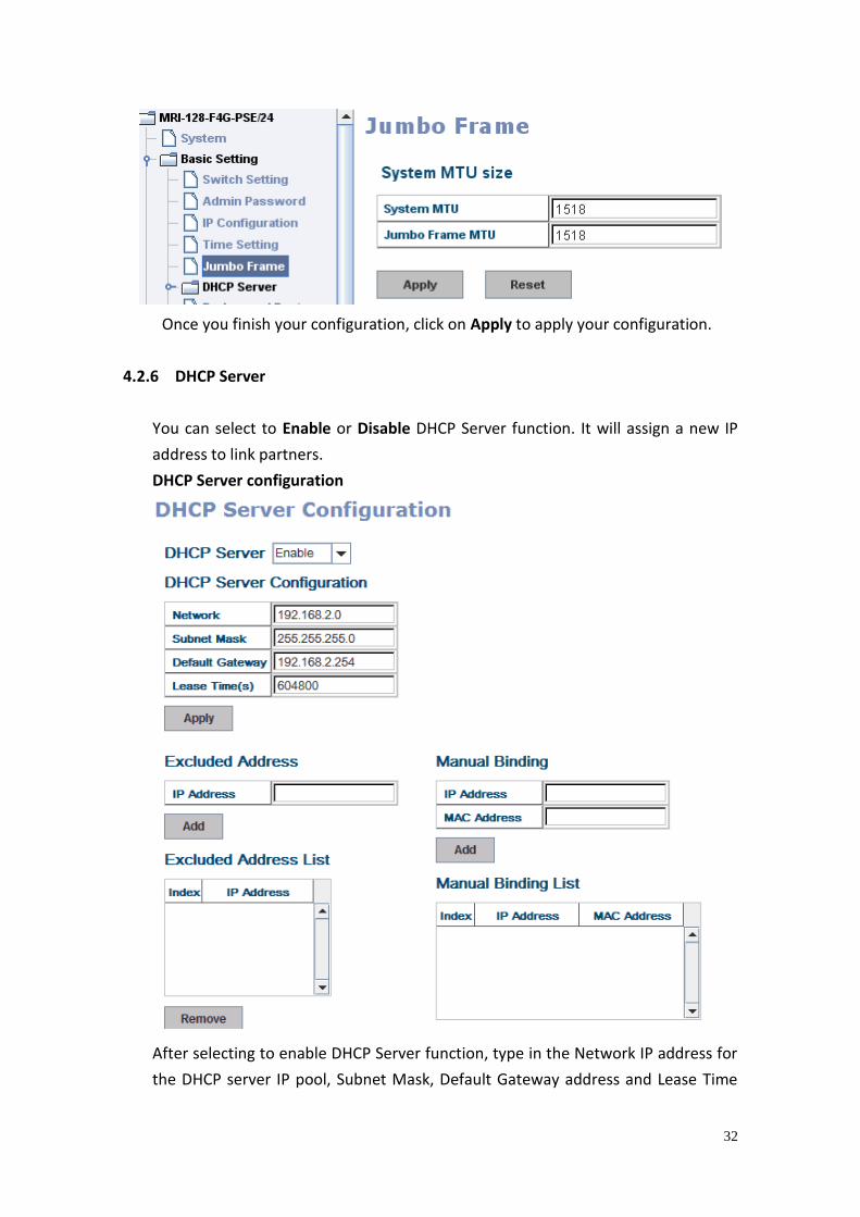
The switch allows you configure the size of the MTU, Maximum Transmission
Unit. The default value is 1,518bytes. The maximum Jumbo Frame size is 9,216
bytes.
32
Once you finish your configuration, click on Apply to apply your configuration.
4.2.6 DHCP Server
You can select to Enable or Disable DHCP Server function. It will assign a new IP
address to link partners.
DHCP Server configuration
After selecting to enable DHCP Server function, type in the Network IP address for
the DHCP server IP pool, Subnet Mask, Default Gateway address and Lease Time
33
for client.
Once you have finished the configuration, click Apply to apply your configuration
Excluded Address:
You can type a specific address into the IP Address field for the DHCP server
reserved IP address.
The IP address that is listed in the Excluded Address List Table will not be assigned
to the network device. Add or remove an IP address from the Excluded Address
List by clicking Add or Remove.
Manual Binding: the switch provides a MAC address and IP address binding and
removing function. You can type in the specified IP and MAC address, then click
Add to add a new MAC&IP address binding rule for a specified link partner, like
PLC or any device without DHCP client function. To remove from the binding list,
just select the rule to remove and click Remove.
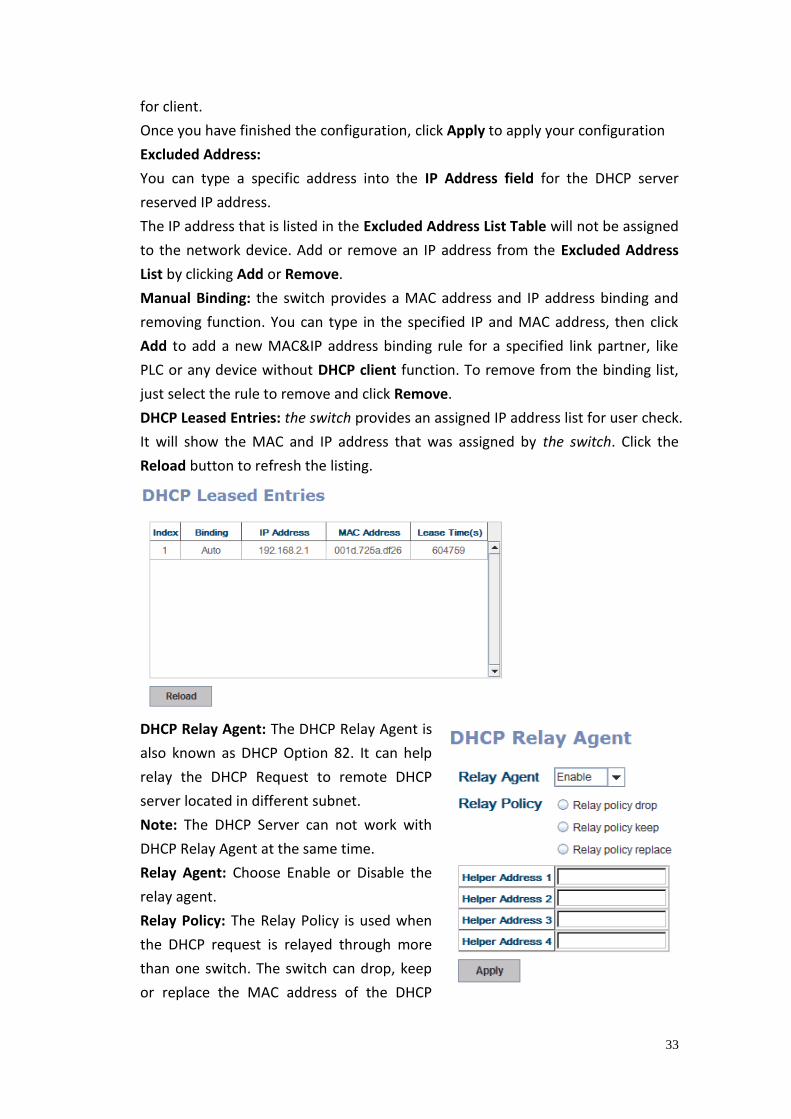
DHCP Leased Entries: the switch provides an assigned IP address list for user check.
It will show the MAC and IP address that was assigned by the switch. Click the
Reload button to refresh the listing.
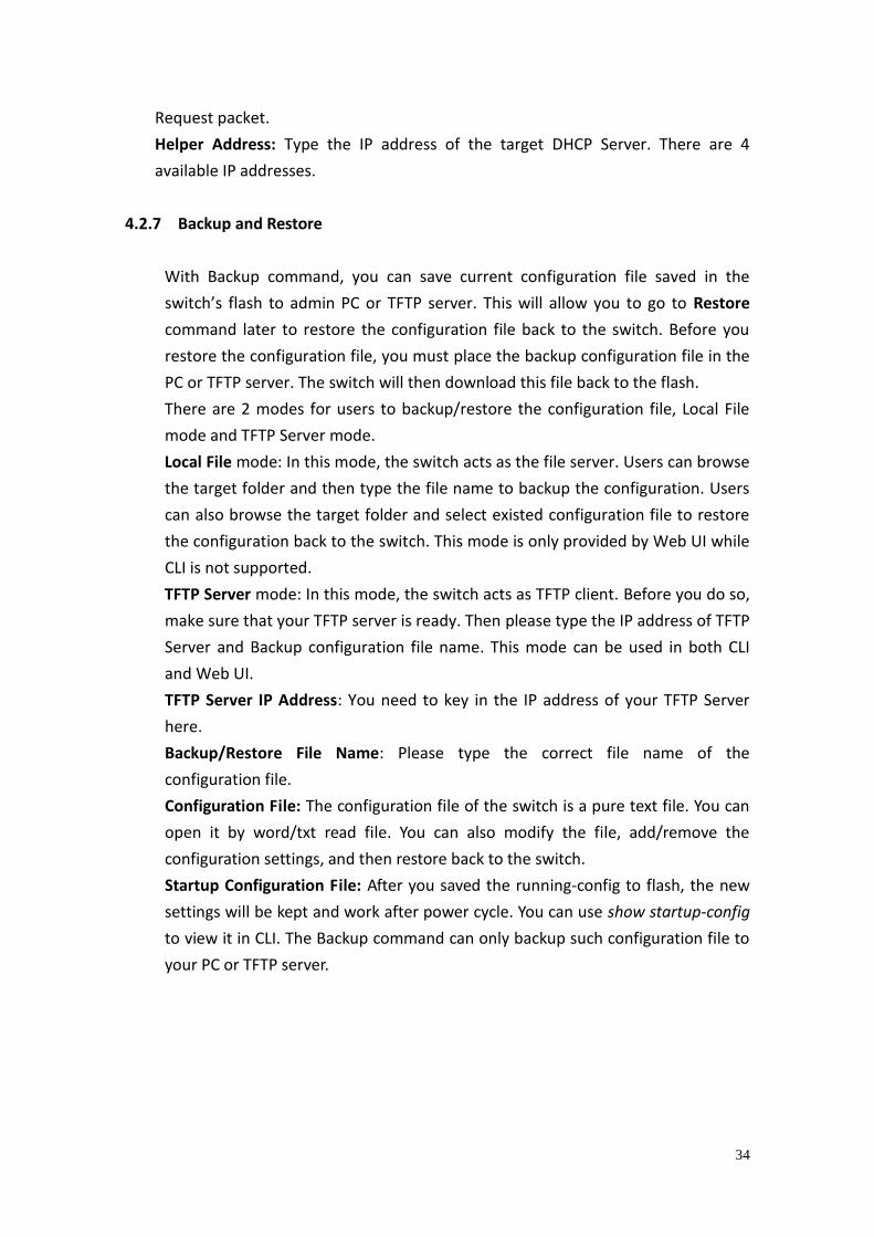
DHCP Relay Agent: The DHCP Relay Agent is
also known as DHCP Option 82. It can help
relay the DHCP Request to remote DHCP
server located in different subnet.
Note: The DHCP Server can not work with
DHCP Relay Agent at the same time.
Relay Agent: Choose Enable or Disable the
relay agent.
Relay Policy: The Relay Policy is used when
the DHCP request is relayed through more
than one switch. The switch can drop, keep
or replace the MAC address of the DHCP
34
Request packet.
Helper Address: Type the IP address of the target DHCP Server. There are 4
available IP addresses.
4.2.7 Backup and Restore
With Backup command, you can save current configuration file saved in the
switch’s flash to admin PC or TFTP server. This will allow you to go to Restore
command later to restore the configuration file back to the switch. Before you
restore the configuration file, you must place the backup configuration file in the
PC or TFTP server. The switch will then download this file back to the flash.
There are 2 modes for users to backup/restore the configuration file, Local File
mode and TFTP Server mode.
Local File mode: In this mode, the switch acts as the file server. Users can browse
the target folder and then type the file name to backup the configuration. Users
can also browse the target folder and select existed configuration file to restore
the configuration back to the switch. This mode is only provided by Web UI while
CLI is not supported.
TFTP Server mode: In this mode, the switch acts as TFTP client. Before you do so,
make sure that your TFTP server is ready. Then please type the IP address of TFTP
Server and Backup configuration file name. This mode can be used in both CLI
and Web UI.
TFTP Server IP Address: You need to key in the IP address of your TFTP Server
here.
Backup/Restore File Name: Please type the correct file name of the
configuration file.
Configuration File: The configuration file of the switch is a pure text file. You can
open it by word/txt read file. You can also modify the file, add/remove the
configuration settings, and then restore back to the switch.
Startup Configuration File: After you saved the running-config to flash, the new
settings will be kept and work after power cycle. You can use show startup-config
to view it in CLI. The Backup command can only backup such configuration file to
your PC or TFTP server.
35
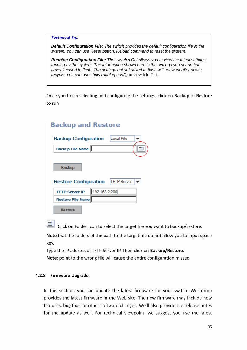
Once you finish selecting and configuring the settings, click on Backup or Restore
to run
Click on Folder icon to select the target file you want to backup/restore.
Note that the folders of the path to the target file do not allow you to input space
key.
Type the IP address of TFTP Server IP. Then click on Backup/Restore.
Note: point to the wrong file will cause the entire configuration missed
4.2.8 Firmware Upgrade
In this section, you can update the latest firmware for your switch. Westermo
provides the latest firmware in the Web site. The new firmware may include new
features, bug fixes or other software changes. We’ll also provide the release notes
for the update as well. For technical viewpoint, we suggest you use the latest
Technical Tip:
Default Configuration File: The switch provides the default configuration file in the
system. You can use Reset button, Reload command to reset the system.
Running Configuration File: The switch’s CLI allows you to view the latest settings
running by the system. The information shown here is the settings you set up but
haven’t saved to flash. The settings not yet saved to flash will not work after power
recycle. You can use show running-config to view it in CLI.
36
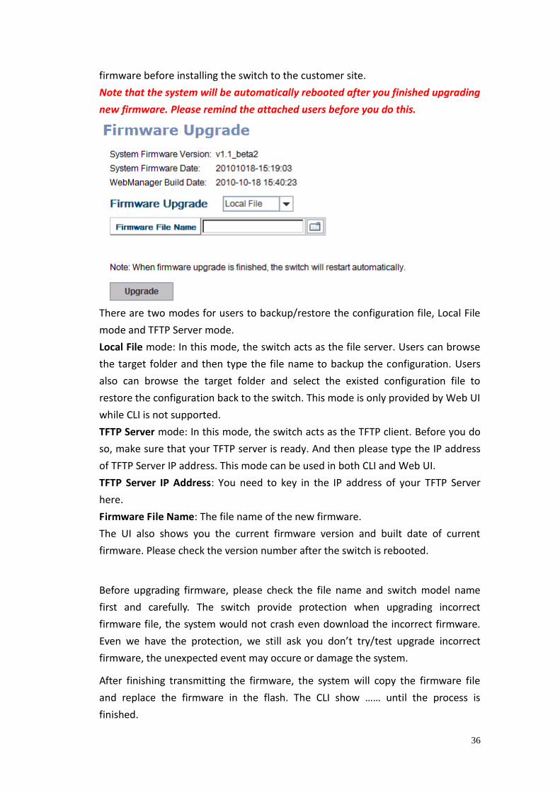
firmware before installing the switch to the customer site.
Note that the system will be automatically rebooted after you finished upgrading
new firmware. Please remind the attached users before you do this.
There are two modes for users to backup/restore the configuration file, Local File
mode and TFTP Server mode.
Local File mode: In this mode, the switch acts as the file server. Users can browse
the target folder and then type the file name to backup the configuration. Users
also can browse the target folder and select the existed configuration file to
restore the configuration back to the switch. This mode is only provided by Web UI
while CLI is not supported.
TFTP Server mode: In this mode, the switch acts as the TFTP client. Before you do
so, make sure that your TFTP server is ready. And then please type the IP address
of TFTP Server IP address. This mode can be used in both CLI and Web UI.
TFTP Server IP Address: You need to key in the IP address of your TFTP Server
here.
Firmware File Name: The file name of the new firmware.
The UI also shows you the current firmware version and built date of current
firmware. Please check the version number after the switch is rebooted.
Before upgrading firmware, please check the file name and switch model name
first and carefully. The switch provide protection when upgrading incorrect
firmware file, the system would not crash even download the incorrect firmware.
Even we have the protection, we still ask you don’t try/test upgrade incorrect
firmware, the unexpected event may occure or damage the system.
After finishing transmitting the firmware, the system will copy the firmware file
and replace the firmware in the flash. The CLI show …… until the process is
finished.
37
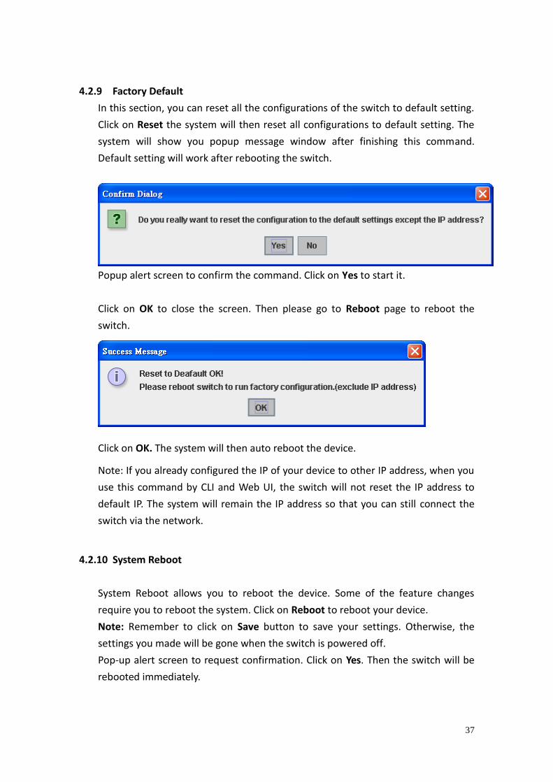
4.2.9 Factory Default
In this section, you can reset all the configurations of the switch to default setting.
Click on Reset the system will then reset all configurations to default setting. The
system will show you popup message window after finishing this command.
Default setting will work after rebooting the switch.
Popup alert screen to confirm the command. Click on Yes to start it.
Click on OK to close the screen. Then please go to Reboot page to reboot the
switch.
Click on OK. The system will then auto reboot the device.
Note: If you already configured the IP of your device to other IP address, when you
use this command by CLI and Web UI, the switch will not reset the IP address to
default IP. The system will remain the IP address so that you can still connect the
switch via the network.
4.2.10 System Reboot
System Reboot allows you to reboot the device. Some of the feature changes
require you to reboot the system. Click on Reboot to reboot your device.
Note: Remember to click on Save button to save your settings. Otherwise, the
settings you made will be gone when the switch is powered off.
Pop-up alert screen to request confirmation. Click on Yes. Then the switch will be
rebooted immediately.
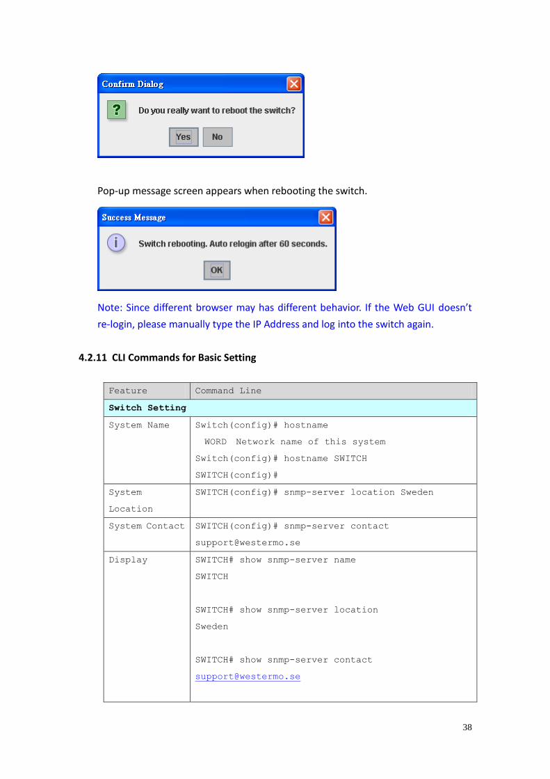
38
Pop-up message screen appears when rebooting the switch.
Note: Since different browser may has different behavior. If the Web GUI doesn’t
re-login, please manually type the IP Address and log into the switch again.
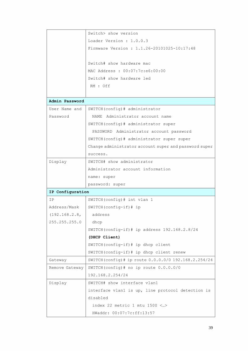
4.2.11 CLI Commands for Basic Setting
Feature Command Line
Switch Setting
System Name Switch(config)# hostname
WORD Network name of this system
Switch(config)# hostname SWITCH
SWITCH(config)#
System
Location
SWITCH(config)# snmp-server location Sweden
System Contact SWITCH(config)# snmp-server contact
Display SWITCH# show snmp-server name
SWITCH
SWITCH# show snmp-server location
Sweden
SWITCH# show snmp-server contact
39
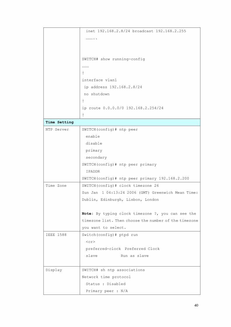
Switch> show version
Loader Version : 1.0.0.3
Firmware Version : 1.1.26-20101025-10:17:48
Switch# show hardware mac
MAC Address : 00:07:7c:e6:00:00
Switch# show hardware led
RM : Off
Admin Password
User Name and
Password
SWITCH(config)# administrator
NAME Administrator account name
SWITCH(config)# administrator super
PASSWORD Administrator account password
SWITCH(config)# administrator super super
Change administrator account super and password super
success.
Display SWITCH# show administrator
Administrator account information
name: super
password: super
IP Configuration
IP
Address/Mask
(192.168.2.8,
255.255.255.0
SWITCH(config)# int vlan 1
SWITCH(config-if)# ip
address
dhcp
SWITCH(config-if)# ip address 192.168.2.8/24
(DHCP Client)
SWITCH(config-if)# ip dhcp client
SWITCH(config-if)# ip dhcp client renew
Gateway SWITCH(config)# ip route 0.0.0.0/0 192.168.2.254/24
Remove Gateway SWITCH(config)# no ip route 0.0.0.0/0
192.168.2.254/24
Display SWITCH# show interface vlan1
interface vlan1 is up, line protocol detection is
disabled
index 22 metric 1 mtu 1500 <…>
HWaddr: 00:07:7c:ff:13:57
40
inet 192.168.2.8/24 broadcast 192.168.2.255
………..
SWITCH# show running-config
………
!
interface vlan1
ip address 192.168.2.8/24
no shutdown
!
ip route 0.0.0.0/0 192.168.2.254/24
!
Time Setting
NTP Server SWITCH(config)# ntp peer
enable
disable
primary
secondary
SWITCH(config)# ntp peer primary
IPADDR
SWITCH(config)# ntp peer primary 192.168.2.200
Time Zone SWITCH(config)# clock timezone 26
Sun Jan 1 04:13:24 2006 (GMT) Greenwich Mean Time:
Dublin, Edinburgh, Lisbon, London
Note: By typing clock timezone ?, you can see the
timezone list. Then choose the number of the timezone
you want to select.
IEEE 1588 Switch(config)# ptpd run
<cr>
preferred-clock Preferred Clock
slave Run as slave
Display SWITCH# sh ntp associations
Network time protocol
Status : Disabled
Primary peer : N/A
41
Secondary peer : N/A
SWITCH# show clock
Sun Jan 1 04:14:19 2006 (GMT) Greenwich Mean Time:
Dublin, Edinburgh, Lisbon, London
SWITCH# show clock timezone
clock timezone (26) (GMT) Greenwich Mean Time:
Dublin, Edinburgh, Lisbon, London
Switch# show ptpd
PTPd is enabled
Mode: Slave
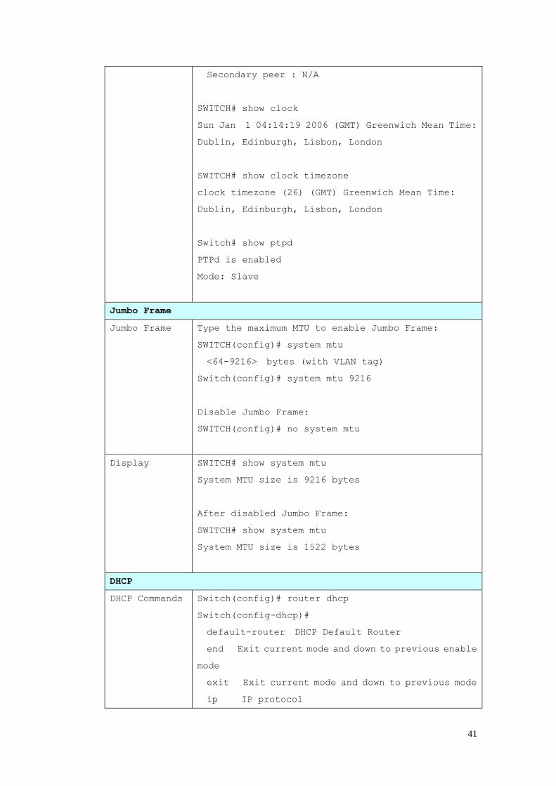
Jumbo Frame
Jumbo Frame Type the maximum MTU to enable Jumbo Frame:
SWITCH(config)# system mtu
<64-9216> bytes (with VLAN tag)
Switch(config)# system mtu 9216
Disable Jumbo Frame:
SWITCH(config)# no system mtu
Display SWITCH# show system mtu
System MTU size is 9216 bytes
After disabled Jumbo Frame:
SWITCH# show system mtu
System MTU size is 1522 bytes
DHCP
DHCP Commands Switch(config)# router dhcp
Switch(config-dhcp)#
default-router DHCP Default Router
end Exit current mode and down to previous enable
mode
exit Exit current mode and down to previous mode
ip IP protocol
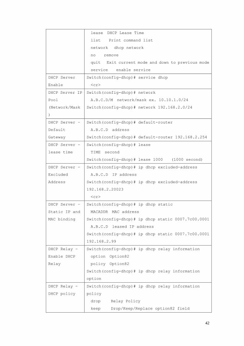
42
lease DHCP Lease Time
list Print command list
network dhcp network
no remove
quit Exit current mode and down to previous mode
service enable service
DHCP Server
Enable
Switch(config-dhcp)# service dhcp
<cr>
DHCP Server IP
Pool
(Network/Mask
)
Switch(config-dhcp)# network
A.B.C.D/M network/mask ex. 10.10.1.0/24
Switch(config-dhcp)# network 192.168.2.0/24
DHCP Server –
Default
Gateway
Switch(config-dhcp)# default-router
A.B.C.D address
Switch(config-dhcp)# default-router 192.168.2.254
DHCP Server –
lease time
Switch(config-dhcp)# lease
TIME second
Switch(config-dhcp)# lease 1000 (1000 second)
DHCP Server –
Excluded
Address
Switch(config-dhcp)# ip dhcp excluded-address
A.B.C.D IP address
Switch(config-dhcp)# ip dhcp excluded-address
192.168.2.20023
<cr>
DHCP Server –
Static IP and
MAC binding
Switch(config-dhcp)# ip dhcp static
MACADDR MAC address
Switch(config-dhcp)# ip dhcp static 0007.7c00.0001
A.B.C.D leased IP address
Switch(config-dhcp)# ip dhcp static 0007.7c00.0001
192.168.2.99
DHCP Relay –
Enable DHCP
Relay
Switch(config-dhcp)# ip dhcp relay information
option Option82
policy Option82
Switch(config-dhcp)# ip dhcp relay information
option
DHCP Relay –
DHCP policy
Switch(config-dhcp)# ip dhcp relay information
policy
drop Relay Policy
keep Drop/Keep/Replace option82 field
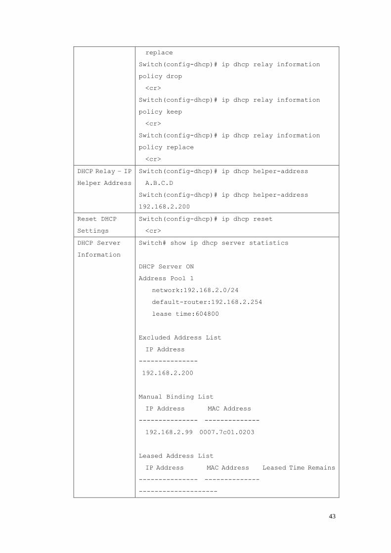
43
replace
Switch(config-dhcp)# ip dhcp relay information
policy drop
<cr>
Switch(config-dhcp)# ip dhcp relay information
policy keep
<cr>
Switch(config-dhcp)# ip dhcp relay information
policy replace
<cr>
DHCP Relay – IP
Helper Address
Switch(config-dhcp)# ip dhcp helper-address
A.B.C.D
Switch(config-dhcp)# ip dhcp helper-address
192.168.2.200
Reset DHCP
Settings
Switch(config-dhcp)# ip dhcp reset
<cr>
DHCP Server
Information
Switch# show ip dhcp server statistics
DHCP Server ON
Address Pool 1
network:192.168.2.0/24
default-router:192.168.2.254
lease time:604800
Excluded Address List
IP Address
---------------
192.168.2.200
Manual Binding List
IP Address MAC Address
--------------- --------------
192.168.2.99 0007.7c01.0203
Leased Address List
IP Address MAC Address Leased Time Remains
--------------- --------------
--------------------
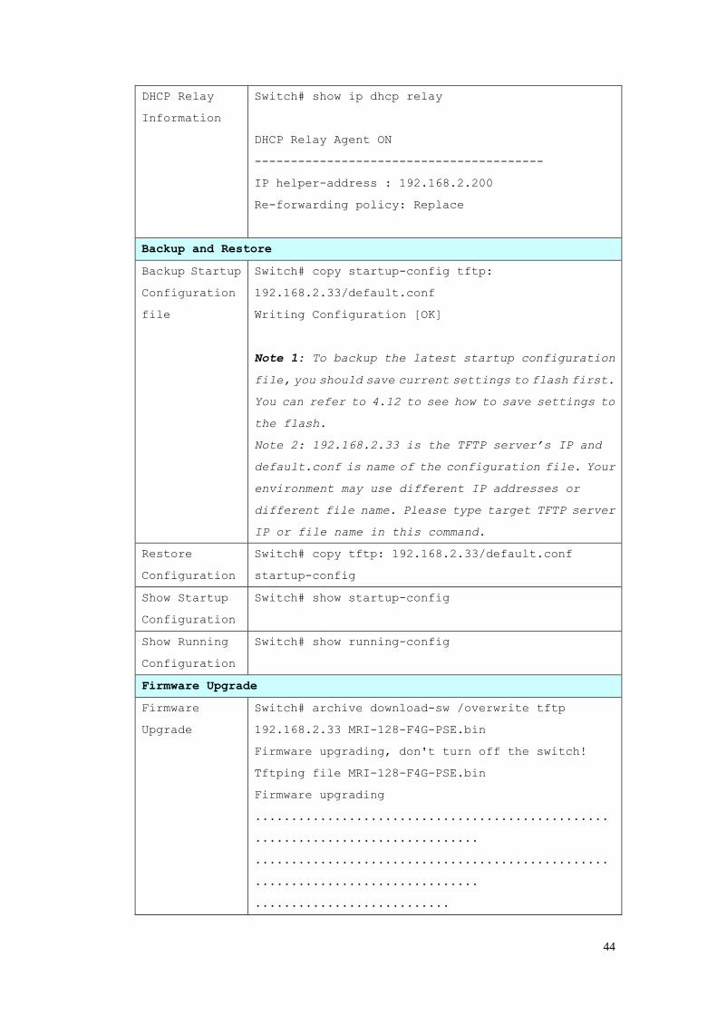
44
DHCP Relay
Information
Switch# show ip dhcp relay
DHCP Relay Agent ON
----------------------------------------
IP helper-address : 192.168.2.200
Re-forwarding policy: Replace
Backup and Restore
Backup Startup
Configuration
file
Switch# copy startup-config tftp:
192.168.2.33/default.conf
Writing Configuration [OK]
Note 1: To backup the latest startup configuration
file, you should save current settings to flash first.
You can refer to 4.12 to see how to save settings to
the flash.
Note 2: 192.168.2.33 is the TFTP server’s IP and
default.conf is name of the configuration file. Your
environment may use different IP addresses or
different file name. Please type target TFTP server
IP or file name in this command.
Restore
Configuration
Switch# copy tftp: 192.168.2.33/default.conf
startup-config
Show Startup
Configuration
Switch# show startup-config
Show Running
Configuration
Switch# show running-config
Firmware Upgrade
Firmware
Upgrade
Switch# archive download-sw /overwrite tftp
192.168.2.33 MRI-128-F4G-PSE.bin
Firmware upgrading, don't turn off the switch!
Tftping file MRI-128-F4G-PSE.bin
Firmware upgrading
.................................................
...............................
.................................................
...............................
...........................

45
Firmware upgrade success!!
Rebooting.......
Factory Default
Factory
Default
Switch# reload default-config file
Reload OK!
Switch# reboot
System Reboot
Reboot Switch# reboot
46
4.3 Port Configuration
Port Configuration group enables you to enable/disable port state, or configure
port auto-negotiation, speed, and duplex, flow control, rate limit control and port
aggregation settings. It also allows you to view port status and aggregation
information.
Following commands are included in this chapter:
4.3.1 Understand the port mapping
4.3.2 Port Control
4.3.3 Port Status
4.3.4 Rate Control
4.3.5 Storm Control
4.3.6 Port Trunking
4.3.7 Command Lines for Port Configuration
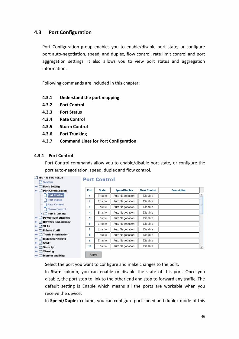
4.3.1 Port Control
Port Control commands allow you to enable/disable port state, or configure the
port auto-negotiation, speed, duplex and flow control.
Select the port you want to configure and make changes to the port.
In State column, you can enable or disable the state of this port. Once you
disable, the port stop to link to the other end and stop to forward any traffic. The
default setting is Enable which means all the ports are workable when you
receive the device.
In Speed/Duplex column, you can configure port speed and duplex mode of this
47
port. Below are the selections you can choose:
Fast Ethernet Port 1~24 (fa1~fa24): AutoNegotiation, 10M Full Duplex(10 Full),
10M Half Duplex(10 Half), 100M Full Duplex(100 Full) and 100M Half Duplex(100
Half).
Gigabit Ethernet Port 25~28: (gi25~gi28): AutoNegotiation, 10M Full Duplex(10
Full), 10M Half Duplex(10 Half), 100M Full Duplex(100 Full), 100M Half
Duplex(100 Half), 1000M Full Duplex(1000 Full), 1000M Half Duplex(1000 Half).
The default mode is Auto Negotiation mode.
In Flow Control column, “Symmetric” means that you need to activate the flow
control function of the remote network device in order to let the flow control of
that corresponding port on the switch to work. “Disable” means that you don’t
need to activate the flow control function of the remote network device, as the
flow control of that corresponding port on the switch will work anyway.
Once you finish configuring the settings, click on Apply to save the configuration.
Technical Tips: If both ends are not at the same speed, they can’t link with each
other. If both ends are not in the same duplex mode, they will be connected by
half mode.
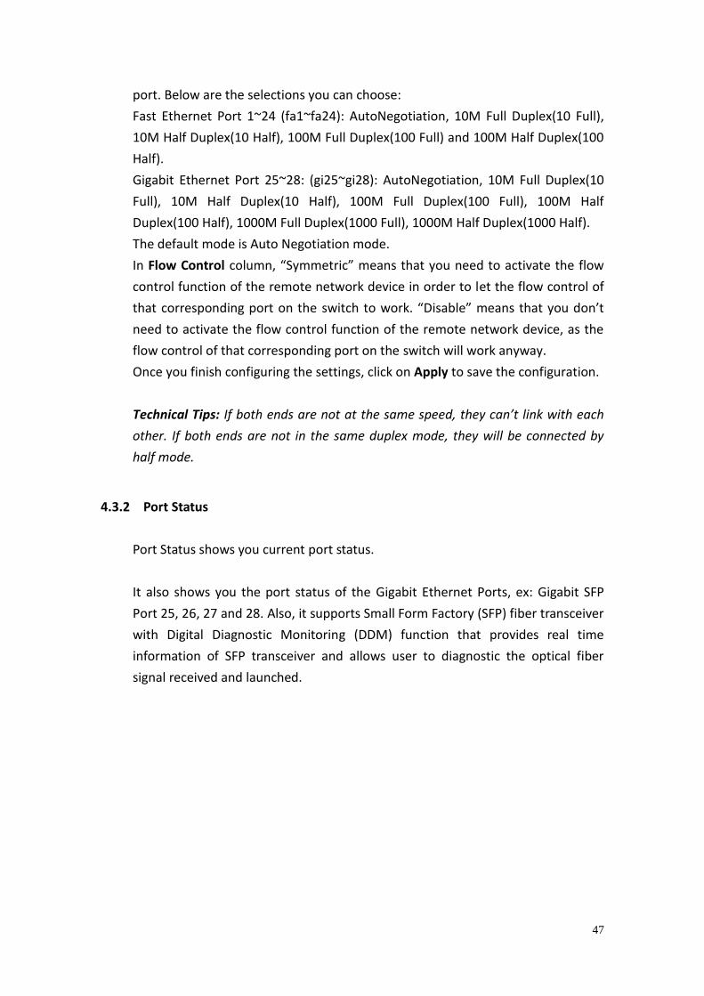
4.3.2 Port Status
Port Status shows you current port status.
It also shows you the port status of the Gigabit Ethernet Ports, ex: Gigabit SFP
Port 25, 26, 27 and 28. Also, it supports Small Form Factory (SFP) fiber transceiver
with Digital Diagnostic Monitoring (DDM) function that provides real time
information of SFP transceiver and allows user to diagnostic the optical fiber
signal received and launched.
48
The description of the columns is as below:
Port: Port interface number.
Type: 100TX -> Fast Ethernet port. 1000TX -> Gigabit Ethernet port.
Link: Link status. Up -> Link UP. Down -> Link Down.
State: Enable -> State is enabled. Disable -> The port is disable/shutdown.
Speed/Duplex: Current working status of the port.
Flow Control: The state of the flow control.
SFP Vendor: Vendor name of the SFP transceiver you plugged.
Wavelength: The wave length of the SFP transceiver you plugged.
Distance: The distance of the SFP transceiver you plugged.
Eject: Eject the DDM SFP transceiver. You can eject one port or eject all by click
the icon “Eject All”.
Temperature: The temperatu re specific and current detected of DDM SFP
transceiver.
Tx Power (dBm): The specification and current transmit power of DDM SFP
transceiver.
Rx Power (dBm): The specification and current received power of DDM SFP
transceiver.
Note:
1. Most of the SFP transceivers provide vendor information which allows your
switch to read it. The User Interface can display vendor name, wave length and
49
distance of all Westermo SFP transceiver family. If you see Unknown info, it may
mean that the vendor doesn’t provide their information or that the information
of their transceiver can’t be read.
2. If the plugged DDM SFP transceiver is not certified by Westermo, the DDM
function will not be supported. But the communication will not be disabled.
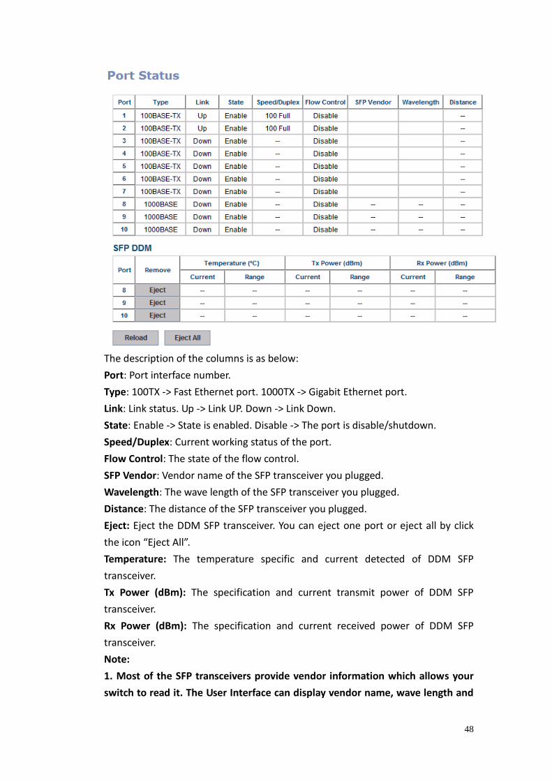
4.3.3 Rate Control
Rate limiting is a form of flow control used to enforce a strict bandwidth limit at a
port. You can program separate transmit (Egress Rule) and receive (Ingress Rule)
rate limits at each port, and even apply the limit to certain packet types as
described below.
Figure shows you the Limit Rate of Ingress and Egress. You can type the volume
step by 64Kbps in the blank.
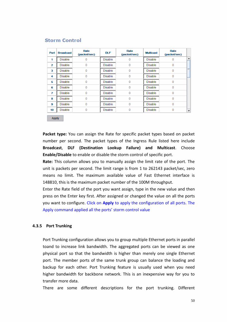
4.3.4 Storm Control
The Storm Control is similar to Rate Control. Rate Control filters all the traffic
over the threshold you input by User Interface. Storm Control allows user to
define the rate for specific Packet Types.
50
Packet type: You can assign the Rate for specific packet types based on packet
number per second. The packet types of the Ingress Rule listed here include
Broadcast, DLF (Destination Lookup Failure) and Multicast. Choose
Enable/Disable to enable or disable the storm control of specific port.
Rate: This column allows you to manually assign the limit rate of the port. The
unit is packets per second. The limit range is from 1 to 262143 packet/sec, zero
means no limit. The maximum available value of Fast Ethernet interface is
148810, this is the maximum packet number of the 100M throughput.
Enter the Rate field of the port you want assign, type in the new value and then
press on the Enter key first. After assigned or changed the value on all the ports
you want to configure. Click on Apply to apply the configuration of all ports. The
Apply command applied all the ports’ storm control value
4.3.5 Port Trunking
Port Trunking configuration allows you to group multiple Ethernet ports in parallel
toand to increase link bandwidth. The aggregated ports can be viewed as one
physical port so that the bandwidth is higher than merely one single Ethernet
port. The member ports of the same trunk group can balance the loading and
backup for each other. Port Trunking feature is usually used when you need
higher bandwidth for backbone network. This is an inexpensive way for you to
transfer more data.
There are some different descriptions for the port trunking. Different
51
manufacturers may use different descriptions for their products, like Link
Aggregation Group (LAG), Link Aggregation Control Protocol, Ethernet Trunk,
Ether Channel…etc. Most of the implementations now conform to IEEE standard,
802.3ad.
The aggregated ports can interconnect to the other switch which also supports
Port Trunking. Westermo Supports 2 types of port trunking. One is Static Trunk,
the other is 802.3ad. When the other end uses 802.3ad LACP, you should assign
802.3ad LACP to the trunk. When the other end uses non-802.3ad, you can then
use Static Trunk.
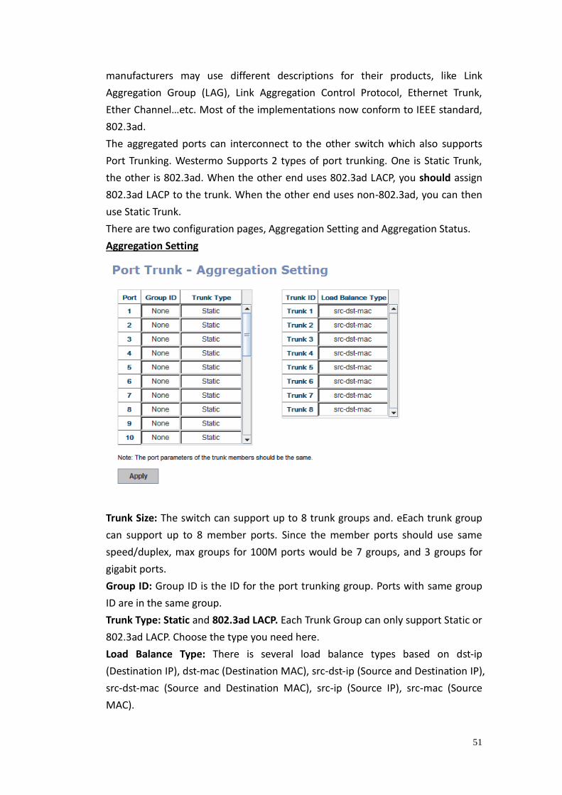
There are two configuration pages, Aggregation Setting and Aggregation Status.
Aggregation Setting
Trunk Size: The switch can support up to 8 trunk groups and. eEach trunk group
can support up to 8 member ports. Since the member ports should use same
speed/duplex, max groups for 100M ports would be 7 groups, and 3 groups for
gigabit ports.
Group ID: Group ID is the ID for the port trunking group. Ports with same group
ID are in the same group.
Trunk Type: Static and 802.3ad LACP. Each Trunk Group can only support Static or
802.3ad LACP. Choose the type you need here.
Load Balance Type: There is several load balance types based on dst-ip
(Destination IP), dst-mac (Destination MAC), src-dst-ip (Source and Destination IP),
src-dst-mac (Source and Destination MAC), src-ip (Source IP), src-mac (Source
MAC).
52
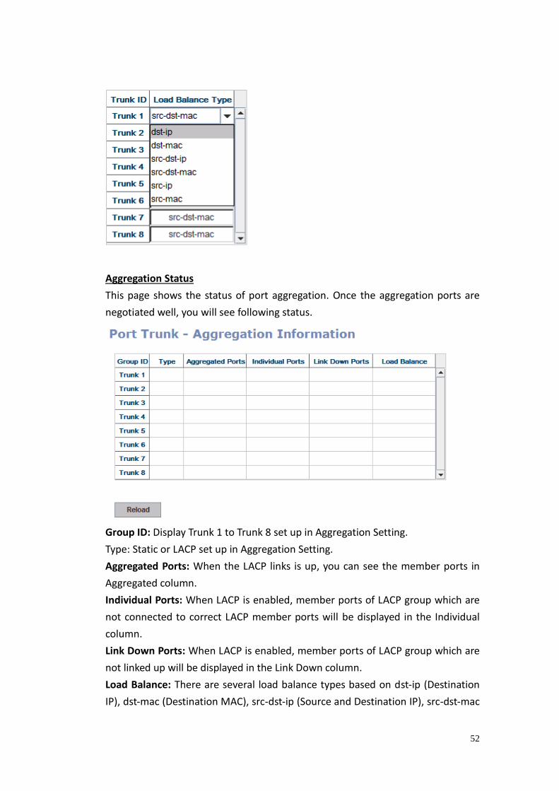
Aggregation Status
This page shows the status of port aggregation. Once the aggregation ports are
negotiated well, you will see following status.
Group ID: Display Trunk 1 to Trunk 8 set up in Aggregation Setting.
Type: Static or LACP set up in Aggregation Setting.
Aggregated Ports: When the LACP links is up, you can see the member ports in
Aggregated column.
Individual Ports: When LACP is enabled, member ports of LACP group which are
not connected to correct LACP member ports will be displayed in the Individual
column.
Link Down Ports: When LACP is enabled, member ports of LACP group which are
not linked up will be displayed in the Link Down column.
Load Balance: There are several load balance types based on dst-ip (Destination
IP), dst-mac (Destination MAC), src-dst-ip (Source and Destination IP), src-dst-mac
53
(Source and Destination MAC), src-ip (Source IP), src-mac (Source MAC).
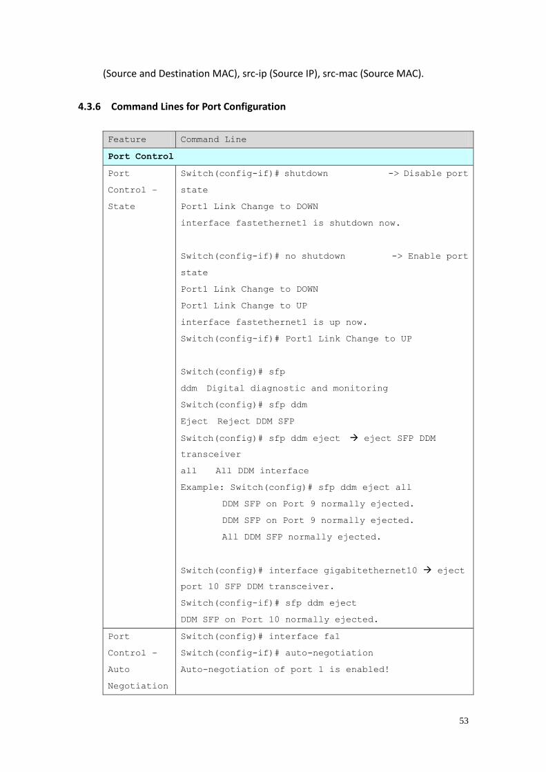
4.3.6 Command Lines for Port Configuration
Feature Command Line
Port Control
Port
Control –
State
Switch(config-if)# shutdown -> Disable port
state
Port1 Link Change to DOWN
interface fastethernet1 is shutdown now.
Switch(config-if)# no shutdown -> Enable port
state
Port1 Link Change to DOWN
Port1 Link Change to UP
interface fastethernet1 is up now.
Switch(config-if)# Port1 Link Change to UP
Switch(config)# sfp
ddm Digital diagnostic and monitoring
Switch(config)# sfp ddm
Eject Reject DDM SFP
Switch(config)# sfp ddm eject eject SFP DDM
transceiver
all All DDM interface
Example: Switch(config)# sfp ddm eject all
DDM SFP on Port 9 normally ejected.
DDM SFP on Port 9 normally ejected.
All DDM SFP normally ejected.
Switch(config)# interface gigabitethernet10 eject
port 10 SFP DDM transceiver.
Switch(config-if)# sfp ddm eject
DDM SFP on Port 10 normally ejected.
Port
Control –
Auto
Negotiation
Switch(config)# interface fa1
Switch(config-if)# auto-negotiation
Auto-negotiation of port 1 is enabled!
54
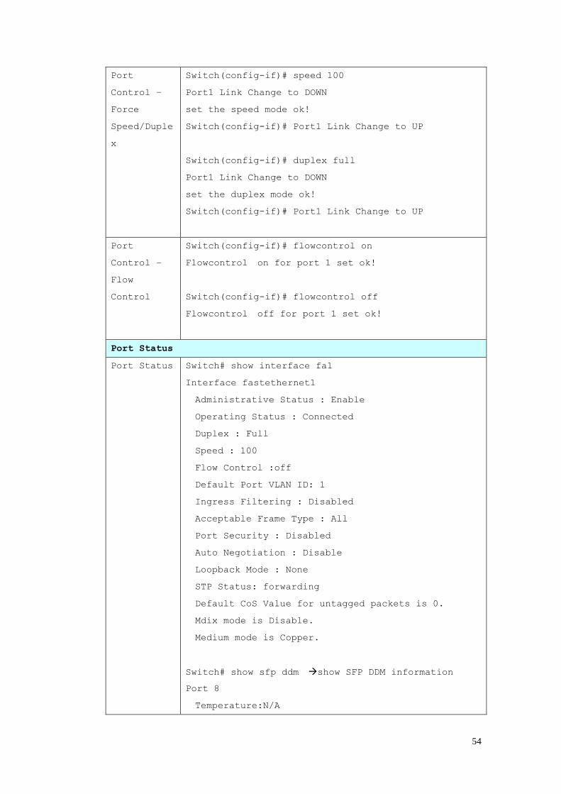
Port
Control –
Force
Speed/Duple
x
Switch(config-if)# speed 100
Port1 Link Change to DOWN
set the speed mode ok!
Switch(config-if)# Port1 Link Change to UP
Switch(config-if)# duplex full
Port1 Link Change to DOWN
set the duplex mode ok!
Switch(config-if)# Port1 Link Change to UP
Port
Control –
Flow
Control
Switch(config-if)# flowcontrol on
Flowcontrol on for port 1 set ok!
Switch(config-if)# flowcontrol off
Flowcontrol off for port 1 set ok!
Port Status
Port Status Switch# show interface fa1
Interface fastethernet1
Administrative Status : Enable
Operating Status : Connected
Duplex : Full
Speed : 100
Flow Control :off
Default Port VLAN ID: 1
Ingress Filtering : Disabled
Acceptable Frame Type : All
Port Security : Disabled
Auto Negotiation : Disable
Loopback Mode : None
STP Status: forwarding
Default CoS Value for untagged packets is 0.
Mdix mode is Disable.
Medium mode is Copper.
Switch# show sfp ddm show SFP DDM information
Port 8
Temperature:N/A
55
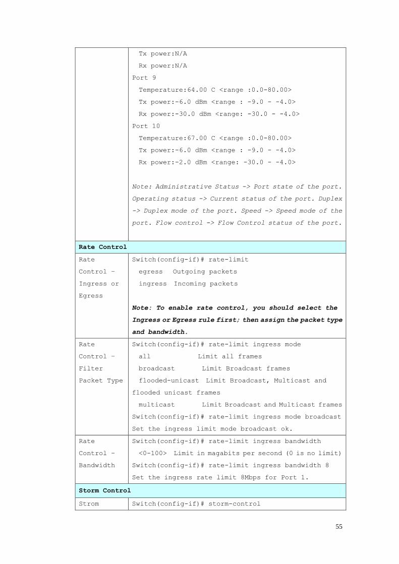
Tx power:N/A
Rx power:N/A
Port 9
Temperature:64.00 C <range :0.0-80.00>
Tx power:-6.0 dBm <range : -9.0 - -4.0>
Rx power:-30.0 dBm <range: -30.0 - -4.0>
Port 10
Temperature:67.00 C <range :0.0-80.00>
Tx power:-6.0 dBm <range : -9.0 - -4.0>
Rx power:-2.0 dBm <range: -30.0 - -4.0>
Note: Administrative Status -> Port state of the port.
Operating status -> Current status of the port. Duplex
-> Duplex mode of the port. Speed -> Speed mode of the
port. Flow control -> Flow Control status of the port.
Rate Control
Rate
Control –
Ingress or
Egress
Switch(config-if)# rate-limit
egress Outgoing packets
ingress Incoming packets
Note: To enable rate control, you should select the
Ingress or Egress rule first; then assign the packet type
and bandwidth.
Rate
Control –
Filter
Packet Type
Switch(config-if)# rate-limit ingress mode
all Limit all frames
broadcast Limit Broadcast frames
flooded-unicast Limit Broadcast, Multicast and
flooded unicast frames
multicast Limit Broadcast and Multicast frames
Switch(config-if)# rate-limit ingress mode broadcast
Set the ingress limit mode broadcast ok.
Rate
Control –
Bandwidth
Switch(config-if)# rate-limit ingress bandwidth
<0-100> Limit in magabits per second (0 is no limit)
Switch(config-if)# rate-limit ingress bandwidth 8
Set the ingress rate limit 8Mbps for Port 1.
Storm Control
Strom Switch(config-if)# storm-control
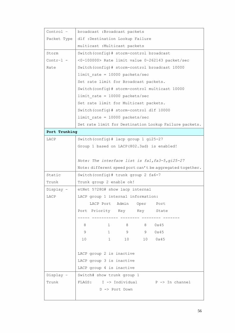
56
Control –
Packet Type
broadcast :Broadcast packets
dlf :Destination Lookup Failure
multicast :Multicast packets
Storm
Contr–l -
Rate
Switch(config)# storm-control broadcast
<0-100000> Rate limit value 0~262143 packet/sec
Switch(config)# storm-control broadcast 10000
limit_rate = 10000 packets/sec
Set rate limit for Broadcast packets.
Switch(config)# storm-control multicast 10000
limit_rate = 10000 packets/sec
Set rate limit for Multicast packets.
Switch(config)# storm-control dlf 10000
limit_rate = 10000 packets/sec
Set rate limit for Destination Lookup Failure packets.
Port Trunking
LACP Switch(config)# lacp group 1 gi25-27
Group 1 based on LACP(802.3ad) is enabled!
Note: The interface list is fa1,fa3-5,gi25-27
Note: different speed port can’t be aggregated together.
Static
Trunk
Switch(config)# trunk group 2 fa6-7
Trunk group 2 enable ok!
Display –
LACP
etNet 5728G# show lacp internal
LACP group 1 internal information:
LACP Port Admin Oper Port
Port Priority Key Key State
----- ----------- -------- -------- -------
8 1 8 8 0x45
9 1 9 9 0x45
10 1 10 10 0x45
LACP group 2 is inactive
LACP group 3 is inactive
LACP group 4 is inactive
Display –
Trunk
Switch# show trunk group 1
FLAGS: I -> Individual P -> In channel
D -> Port Down
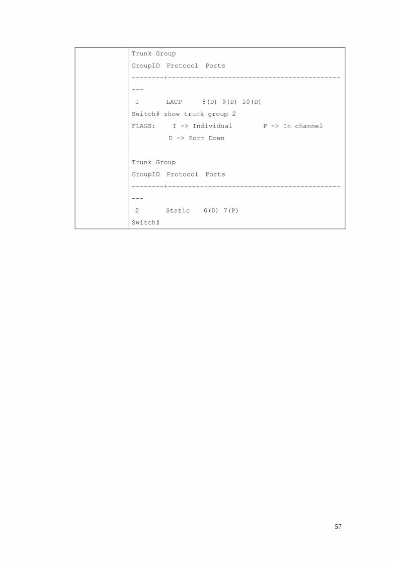
57
Trunk Group
GroupID Protocol Ports
--------+---------+---------------------------------
---
1 LACP 8(D) 9(D) 10(D)
Switch# show trunk group 2
FLAGS: I -> Individual P -> In channel
D -> Port Down
Trunk Group
GroupID Protocol Ports
--------+---------+---------------------------------
---
2 Static 6(D) 7(P)
Switch#
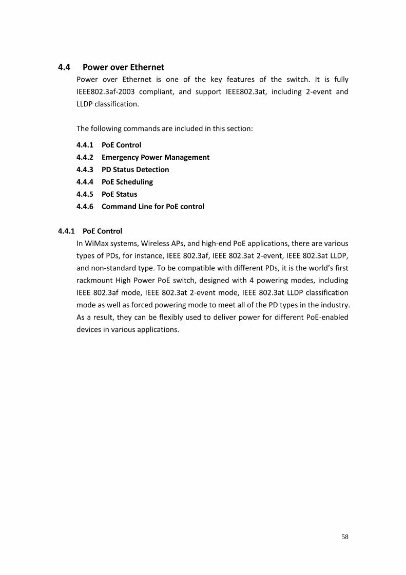
58
4.4 Power over Ethernet Power over Ethernet is one of the key features of the switch. It is fully
IEEE802.3af-2003 compliant, and support IEEE802.3at, including 2-event and
LLDP classification.
The following commands are included in this section:
4.4.1 PoE Control
4.4.2 Emergency Power Management
4.4.3 PD Status Detection
4.4.4 PoE Scheduling
4.4.5 PoE Status
4.4.6 Command Line for PoE control
4.4.1 PoE Control
In WiMax systems, Wireless APs, and high-end PoE applications, there are various
types of PDs, for instance, IEEE 802.3af, IEEE 802.3at 2-event, IEEE 802.3at LLDP,
and non-standard type. To be compatible with different PDs, it is the world’s first
rackmount High Power PoE switch, designed with 4 powering modes, including
IEEE 802.3af mode, IEEE 802.3at 2-event mode, IEEE 802.3at LLDP classification
mode as well as forced powering mode to meet all of the PD types in the industry.
As a result, they can be flexibly used to deliver power for different PoE-enabled
devices in various applications.
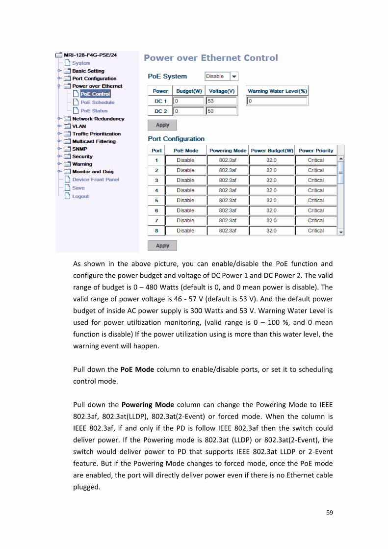
59
As shown in the above picture, you can enable/disable the PoE function and
configure the power budget and voltage of DC Power 1 and DC Power 2. The valid
range of budget is 0 – 480 Watts (default is 0, and 0 mean power is disable). The
valid range of power voltage is 46 - 57 V (default is 53 V). And the default power
budget of inside AC power supply is 300 Watts and 53 V. Warning Water Level is
used for power utiltization monitoring, (valid range is 0 – 100 %, and 0 mean
function is disable) If the power utilization using is more than this water level, the
warning event will happen.
Pull down the PoE Mode column to enable/disable ports, or set it to scheduling
control mode.
Pull down the Powering Mode column can change the Powering Mode to IEEE
802.3af, 802.3at(LLDP), 802.3at(2-Event) or forced mode. When the column is
IEEE 802.3af, if and only if the PD is follow IEEE 802.3af then the switch could
deliver power. If the Powering mode is 802.3at (LLDP) or 802.3at(2-Event), the
switch would deliver power to PD that supports IEEE 802.3at LLDP or 2-Event
feature. But if the Powering Mode changes to forced mode, once the PoE mode
are enabled, the port will directly deliver power even if there is no Ethernet cable
plugged.
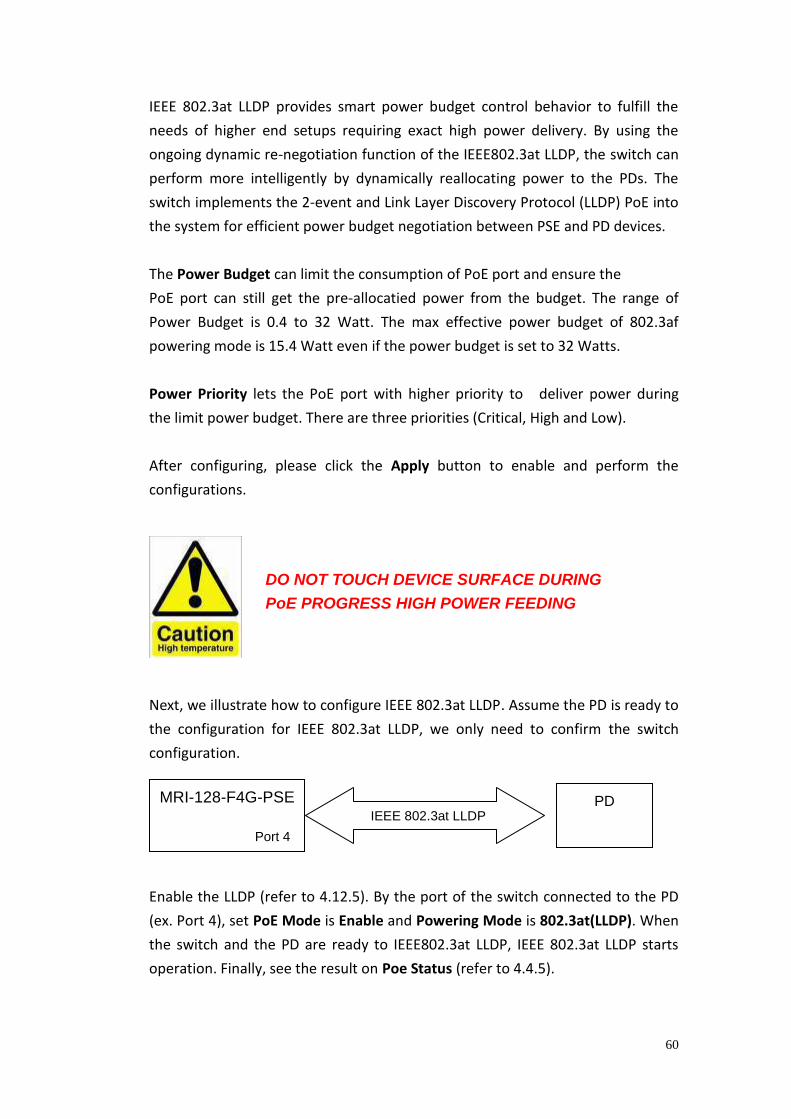
60
IEEE 802.3at LLDP provides smart power budget control behavior to fulfill the
needs of higher end setups requiring exact high power delivery. By using the
ongoing dynamic re-negotiation function of the IEEE802.3at LLDP, the switch can
perform more intelligently by dynamically reallocating power to the PDs. The
switch implements the 2-event and Link Layer Discovery Protocol (LLDP) PoE into
the system for efficient power budget negotiation between PSE and PD devices.
The Power Budget can limit the consumption of PoE port and ensure the
PoE port can still get the pre-allocatied power from the budget. The range of
Power Budget is 0.4 to 32 Watt. The max effective power budget of 802.3af
powering mode is 15.4 Watt even if the power budget is set to 32 Watts.
Power Priority lets the PoE port with higher priority to deliver power during
the limit power budget. There are three priorities (Critical, High and Low).
After configuring, please click the Apply button to enable and perform the
configurations.
Next, we illustrate how to configure IEEE 802.3at LLDP. Assume the PD is ready to
the configuration for IEEE 802.3at LLDP, we only need to confirm the switch
configuration.
Enable the LLDP (refer to 4.12.5). By the port of the switch connected to the PD
(ex. Port 4), set PoE Mode is Enable and Powering Mode is 802.3at(LLDP). When
the switch and the PD are ready to IEEE802.3at LLDP, IEEE 802.3at LLDP starts
operation. Finally, see the result on Poe Status (refer to 4.4.5).
MRI-128-F4G-PSE
Port 4
PD IEEE 802.3at LLDP
DO NOT TOUCH DEVICE SURFACE DURING
PoE PROGRESS HIGH POWER FEEDING

61
4.4.2 Emergency Power Management
The switch is equipped with dual 48VDC power inputs for providing true network
redundancy. An alarm relay output signals when a power input fails or other
critical events occur. To ensure reliable power delivery, other advanced PoE
power management features include individual port status monitoring,
emergency power management (3 power supply indication inputs for quick
shutdown of ports according to pre-defined priority table in cases where power
supply failure occurs) and voltage/current monitoring and regulation. Power
management allows the switch to determine the exact power draw per port and
to balance each port PoE power output accordingly. This, in turn, allows the
switch to power higher and lower wattage devices according to user-definable
parameters such as maximum available power, port priority (critical, high, low),
and maximum allowable power per port. For the same level priority, the priority
order is decided by port number. The port number sequence of
MRI-128-F4G-PSE/24 from high priority to low priority is 3-4-1-2-7-8-5-6-
11-12-9-10-15-16-13-14-19-20-17-18-23-24-21-22-27-28-25-26.
4.4.3 PD Status Detection
The switch delivers a useful function – PD Status Detection. This provides
automatic detection of a remote device powered by the switch. If the remote
system crashes or is unstable, the switch will perform a system reboot by turning
off and on again to trigger the remote device. The following figure shows the Web
configure interface for Power over Ethernet PD Status Detection.
You can enable/disable PD Status Detection function and type in the IP address
that you want to detect. The Cycle Time is the gap per detection. After
configuring, please click the Apply button to enable and perform the functions.
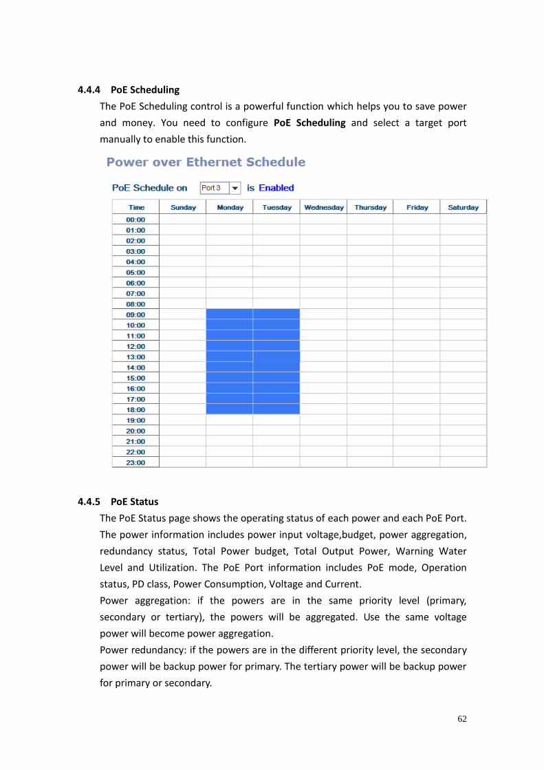
62
4.4.4 PoE Scheduling
The PoE Scheduling control is a powerful function which helps you to save power
and money. You need to configure PoE Scheduling and select a target port
manually to enable this function.
4.4.5 PoE Status
The PoE Status page shows the operating status of each power and each PoE Port.
The power information includes power input voltage,budget, power aggregation,
redundancy status, Total Power budget, Total Output Power, Warning Water
Level and Utilization. The PoE Port information includes PoE mode, Operation
status, PD class, Power Consumption, Voltage and Current.
Power aggregation: if the powers are in the same priority level (primary,
secondary or tertiary), the powers will be aggregated. Use the same voltage
power will become power aggregation.
Power redundancy: if the powers are in the different priority level, the secondary
power will be backup power for primary. The tertiary power will be backup power
for primary or secondary.
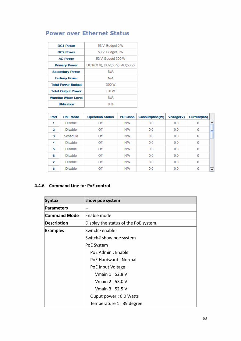
63
4.4.6 Command Line for PoE control
Syntax show poe system
Parameters --
Command Mode Enable mode
Description Display the status of the PoE system.
Examples Switch> enable
Switch# show poe system
PoE System
PoE Admin : Enable
PoE Hardward : Normal
PoE Input Voltage :
Vmain 1 : 52.8 V
Vmain 2 : 53.0 V
Vmain 3 : 52.5 V
Ouput power : 0.0 Watts
Temperature 1 : 39 degree
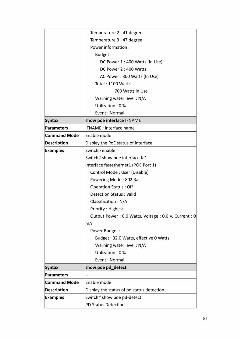
64
Temperature 2 : 41 degree
Temperature 3 : 47 degree
Power information :
Budget :
DC Power 1 : 400 Watts (In Use)
DC Power 2 : 400 Watts
AC Power : 300 Watts (In Use)
Total : 1100 Watts
700 Watts in Use
Warning water level : N/A
Utilization : 0 %
Event : Normal
Syntax show poe interface IFNAME
Parameters IFNAME : interface name
Command Mode Enable mode
Description Display the PoE status of interface.
Examples Switch> enable
Switch# show poe interface fa1
Interface fastethernet1 (POE Port 1)
Control Mode : User (Disable)
Powering Mode : 802.3af
Operation Status : Off
Detection Status : Valid
Classification : N/A
Priority : Highest
Output Power : 0.0 Watts, Voltage : 0.0 V, Current : 0
mA
Power Budget :
Budget : 32.0 Watts, effective 0 Watts
Warning water level : N/A
Utilization : 0 %
Event : Normal
Syntax show poe pd_detect
Parameters --
Command Mode Enable mode
Description Display the status of pd status detection.
Examples Switch# show poe pd-detect
PD Status Detection
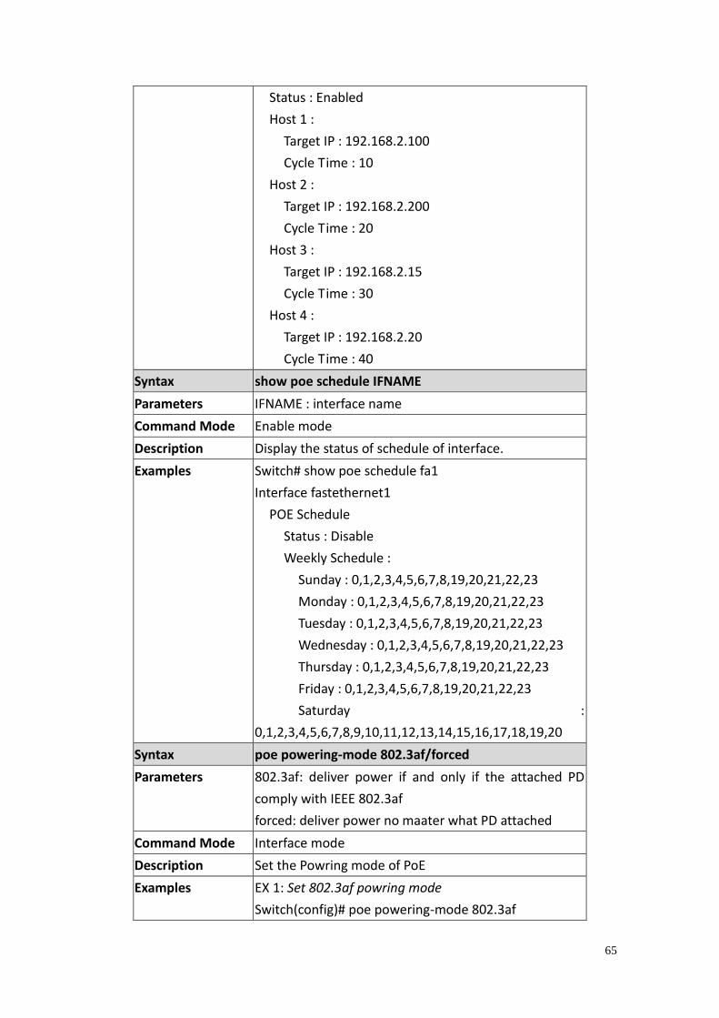
65
Status : Enabled
Host 1 :
Target IP : 192.168.2.100
Cycle Time : 10
Host 2 :
Target IP : 192.168.2.200
Cycle Time : 20
Host 3 :
Target IP : 192.168.2.15
Cycle Time : 30
Host 4 :
Target IP : 192.168.2.20
Cycle Time : 40
Syntax show poe schedule IFNAME
Parameters IFNAME : interface name
Command Mode Enable mode
Description Display the status of schedule of interface.
Examples Switch# show poe schedule fa1
Interface fastethernet1
POE Schedule
Status : Disable
Weekly Schedule :
Sunday : 0,1,2,3,4,5,6,7,8,19,20,21,22,23
Monday : 0,1,2,3,4,5,6,7,8,19,20,21,22,23
Tuesday : 0,1,2,3,4,5,6,7,8,19,20,21,22,23
Wednesday : 0,1,2,3,4,5,6,7,8,19,20,21,22,23
Thursday : 0,1,2,3,4,5,6,7,8,19,20,21,22,23
Friday : 0,1,2,3,4,5,6,7,8,19,20,21,22,23
Saturday :
0,1,2,3,4,5,6,7,8,9,10,11,12,13,14,15,16,17,18,19,20
Syntax poe powering-mode 802.3af/forced
Parameters 802.3af: deliver power if and only if the attached PD
comply with IEEE 802.3af
forced: deliver power no maater what PD attached
Command Mode Interface mode
Description Set the Powring mode of PoE
Examples EX 1: Set 802.3af powring mode
Switch(config)# poe powering-mode 802.3af
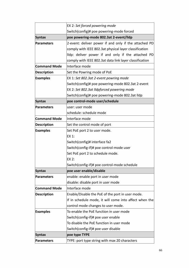
66
EX 2: Set forced powering mode
Switch(config)# poe powering-mode forced
Syntax poe powering-mode 802.3at 2-event/lldp
Parameters 2-event: deliver power if and only if the attached PD
comply with IEEE 802.3at physical layer classification
lldp: deliver power if and only if the attached PD
comply with IEEE 802.3at data link layer classification
Command Mode Interface mode
Description Set the Powring mode of PoE
Examples EX 1: Set 802.3at 2-event powring mode
Switch(config)# poe powering-mode 802.3at 2-event
EX 2: Set 802.3at lldpforced powering mode
Switch(config)# poe powering-mode 802.3at lldp
Syntax poe control-mode user/schedule
Parameters user: user mode
schedule: schedule mode
Command Mode Interface mode
Description Set the control mode of port
Examples Set PoE port 2 to user mode.
EX 1:
Switch(config)# interface fa2
Switch(config-if)# poe control-mode user
Set PoE port 2 to schedule mode.
EX 2:
Switch(config-if)# poe control-mode schedule
Syntax poe user enable/disable
Parameters enable: enable port in user mode
disable: disable port in user mode
Command Mode Interface mode
Description Enable/Disable the PoE of the port in user mode.
If in schedule mode, it will come into affect when the
control mode changes to user mode.
Examples To enable the PoE function in user mode
Switch(config-if)# poe user enable
To disable the PoE function in user mode
Switch(config-if)# poe user disable
Syntax poe type TYPE
Parameters TYPE: port type string with max 20 characters
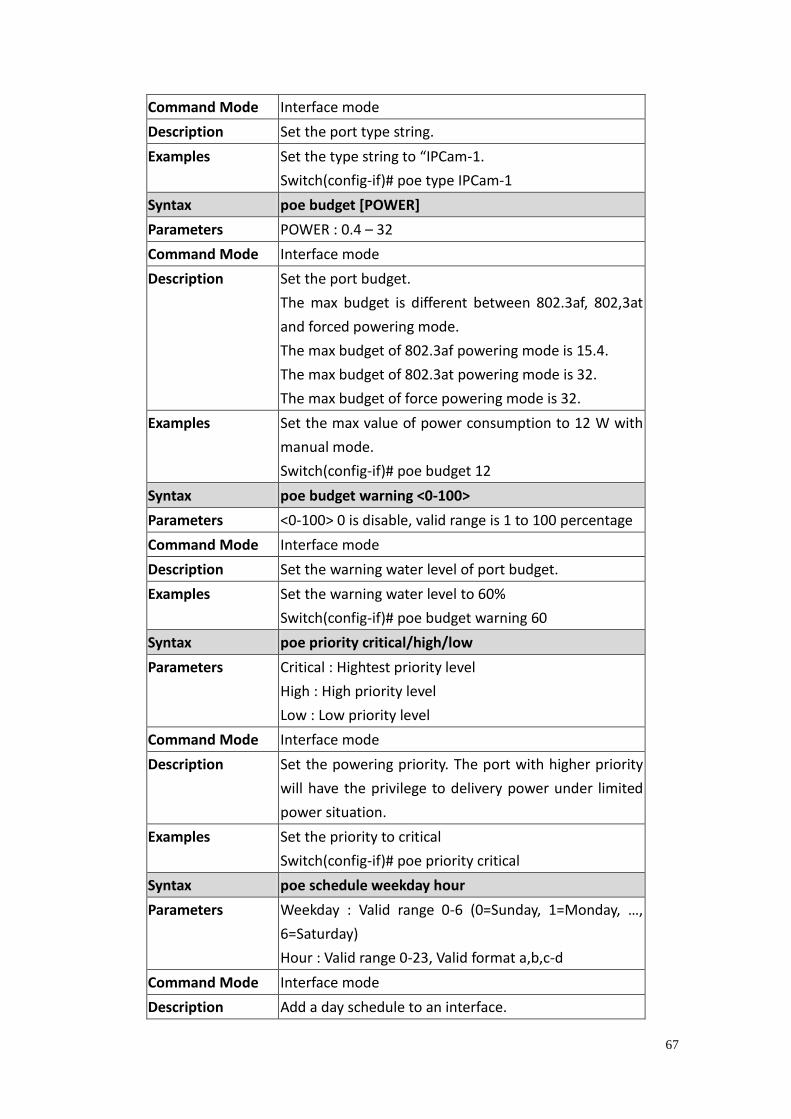
67
Command Mode Interface mode
Description Set the port type string.
Examples Set the type string to “IPCam-1.
Switch(config-if)# poe type IPCam-1
Syntax poe budget [POWER]
Parameters POWER : 0.4 – 32
Command Mode Interface mode
Description Set the port budget.
The max budget is different between 802.3af, 802,3at
and forced powering mode.
The max budget of 802.3af powering mode is 15.4.
The max budget of 802.3at powering mode is 32.
The max budget of force powering mode is 32.
Examples Set the max value of power consumption to 12 W with
manual mode.
Switch(config-if)# poe budget 12
Syntax poe budget warning <0-100>
Parameters <0-100> 0 is disable, valid range is 1 to 100 percentage
Command Mode Interface mode
Description Set the warning water level of port budget.
Examples Set the warning water level to 60%
Switch(config-if)# poe budget warning 60
Syntax poe priority critical/high/low
Parameters Critical : Hightest priority level
High : High priority level
Low : Low priority level
Command Mode Interface mode
Description Set the powering priority. The port with higher priority
will have the privilege to delivery power under limited
power situation.
Examples Set the priority to critical
Switch(config-if)# poe priority critical
Syntax poe schedule weekday hour
Parameters Weekday : Valid range 0-6 (0=Sunday, 1=Monday, …,
6=Saturday)
Hour : Valid range 0-23, Valid format a,b,c-d
Command Mode Interface mode
Description Add a day schedule to an interface.
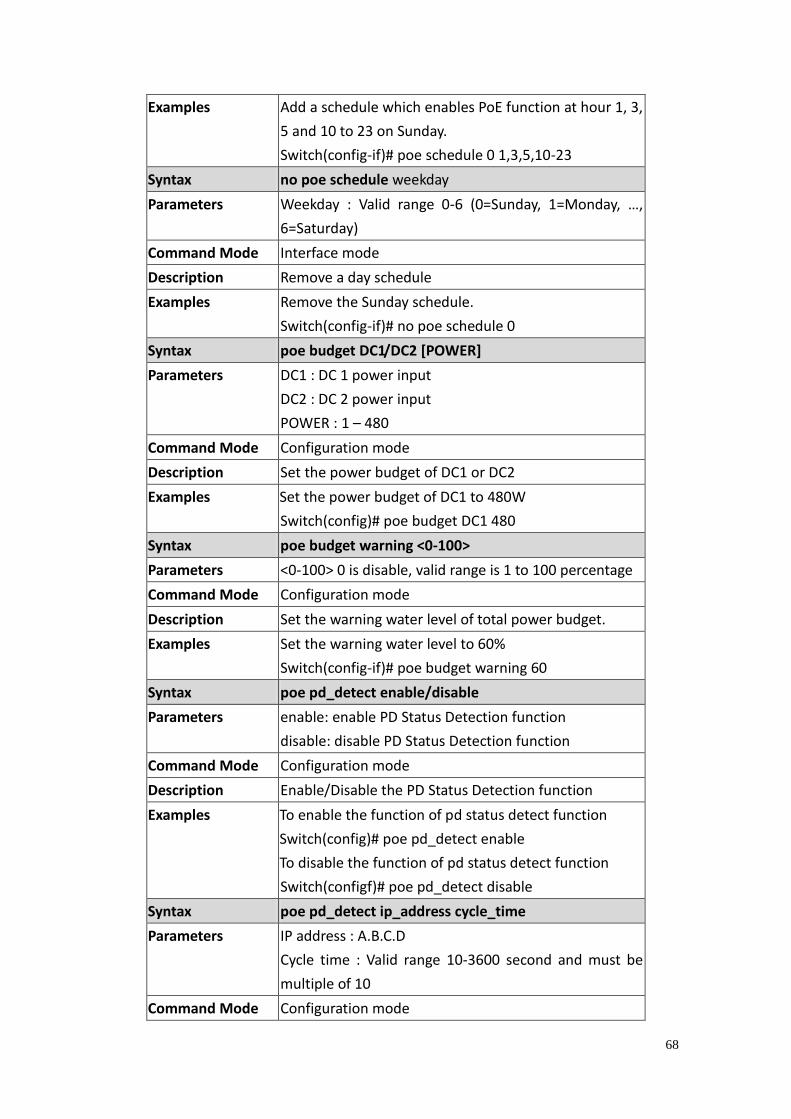
68
Examples Add a schedule which enables PoE function at hour 1, 3,
5 and 10 to 23 on Sunday.
Switch(config-if)# poe schedule 0 1,3,5,10-23
Syntax no poe schedule weekday
Parameters Weekday : Valid range 0-6 (0=Sunday, 1=Monday, …,
6=Saturday)
Command Mode Interface mode
Description Remove a day schedule
Examples Remove the Sunday schedule.
Switch(config-if)# no poe schedule 0
Syntax poe budget DC1/DC2 [POWER]
Parameters DC1 : DC 1 power input
DC2 : DC 2 power input
POWER : 1 – 480
Command Mode Configuration mode
Description Set the power budget of DC1 or DC2
Examples Set the power budget of DC1 to 480W
Switch(config)# poe budget DC1 480
Syntax poe budget warning <0-100>
Parameters <0-100> 0 is disable, valid range is 1 to 100 percentage
Command Mode Configuration mode
Description Set the warning water level of total power budget.
Examples Set the warning water level to 60%
Switch(config-if)# poe budget warning 60
Syntax poe pd_detect enable/disable
Parameters enable: enable PD Status Detection function
disable: disable PD Status Detection function
Command Mode Configuration mode
Description Enable/Disable the PD Status Detection function
Examples To enable the function of pd status detect function
Switch(config)# poe pd_detect enable
To disable the function of pd status detect function
Switch(configf)# poe pd_detect disable
Syntax poe pd_detect ip_address cycle_time
Parameters IP address : A.B.C.D
Cycle time : Valid range 10-3600 second and must be
multiple of 10
Command Mode Configuration mode

69
Description Apply a rule of PD Status Detection.
Examples Apply a rule which ping 192.160.1.2 per 20 seconds.
And if 192.160.1.2 is timeout, pd status detection will
re-enable the PoE.
Switch(config)# poe pd_detect 192.160.1.2 20
70
4.5 Network Redundancy
The switch firmware supports standard RSTP, MSTP, Multiple Super Ring, and Rapid
Dual Homing.
Multiple Spanning Tree Protocol (MSTP) is a direct extension of RSTP. It can provide
an independent spanning tree for different VLANs. It simplifies network
management, provides for even faster convergence than RSTP by limiting the size
of each region, and prevents VLAN members from being segmented from the rest
of the group (as sometimes occurs with IEEE 802.1D STP).
Multiple Super Ring (MSR) technology supports 0 milliseconds for restore and less
than 300 milliseconds for failover.
Advanced Rapid Dual Homing (RDH) technology also facilitates the switch to
connect with a core managed switch easily and conveniently. With RDH technology,
you can also group several Rapid Super Rings or RSTP cloud together, which is also
known as Auto Ring Coupling.
Besides ring technology, the switch also supports 802.1D-2004 version Rapid
Spanning Tree Protocol (RSTP). New version of RSTP standard includes 802.1D-1998
STP, 802.1w RSTP.
Following commands are included in this section:
4.5.1 RSTP
4.5.2 RSTP Info
4.5.3 MSTP Configuration
4.5.4 MSTP Port Configuration
4.5.5 MSTP Information
4.5.6 Multiple Super Ring
4.5.7 Ring Info
4.5.8 Command Lines for Network Redundancy
4.5.1 RSTP
RSTP is the abbreviation of Rapid Spanning Tree Protocol. If a switch has more
than one path to a destination, it will lead to message loops that can generate
broadcast storms and quickly bog down a network. The spanning tree was
created to combat the negative effects of message loops in switched networks. A
spanning tree uses a spanning tree algorithm (STA) to automatically sense
whether a switch has more than one way to communicate with a node. It will
then select the best path (primary), and block the other path(s). It will also keep
track of the blocked path(s) in case the primary path fails. Spanning Tree Protocol
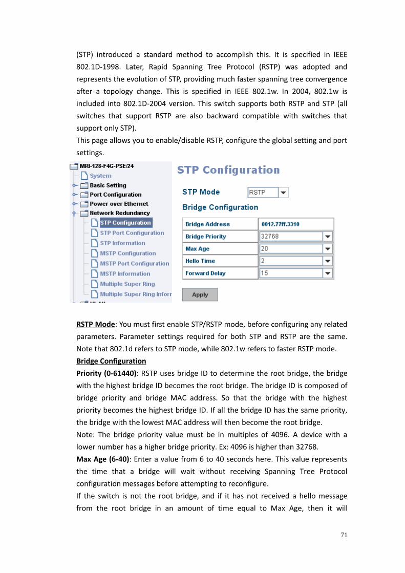
71
(STP) introduced a standard method to accomplish this. It is specified in IEEE
802.1D-1998. Later, Rapid Spanning Tree Protocol (RSTP) was adopted and
represents the evolution of STP, providing much faster spanning tree convergence
after a topology change. This is specified in IEEE 802.1w. In 2004, 802.1w is
included into 802.1D-2004 version. This switch supports both RSTP and STP (all
switches that support RSTP are also backward compatible with switches that
support only STP).
This page allows you to enable/disable RSTP, configure the global setting and port
settings.
RSTP Mode: You must first enable STP/RSTP mode, before configuring any related
parameters. Parameter settings required for both STP and RSTP are the same.
Note that 802.1d refers to STP mode, while 802.1w refers to faster RSTP mode.
Bridge Configuration
Priority (0-61440): RSTP uses bridge ID to determine the root bridge, the bridge
with the highest bridge ID becomes the root bridge. The bridge ID is composed of
bridge priority and bridge MAC address. So that the bridge with the highest
priority becomes the highest bridge ID. If all the bridge ID has the same priority,
the bridge with the lowest MAC address will then become the root bridge.
Note: The bridge priority value must be in multiples of 4096. A device with a
lower number has a higher bridge priority. Ex: 4096 is higher than 32768.
Max Age (6-40): Enter a value from 6 to 40 seconds here. This value represents
the time that a bridge will wait without receiving Spanning Tree Protocol
configuration messages before attempting to reconfigure.
If the switch is not the root bridge, and if it has not received a hello message
from the root bridge in an amount of time equal to Max Age, then it will
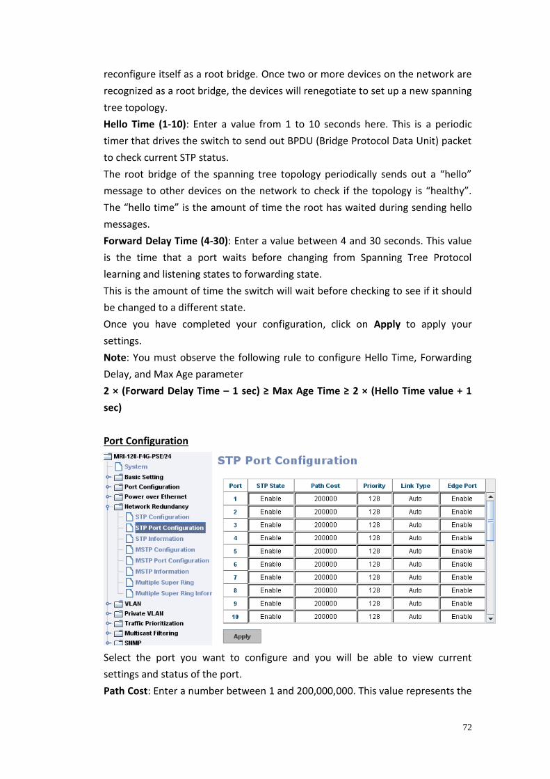
72
reconfigure itself as a root bridge. Once two or more devices on the network are
recognized as a root bridge, the devices will renegotiate to set up a new spanning
tree topology.
Hello Time (1-10): Enter a value from 1 to 10 seconds here. This is a periodic
timer that drives the switch to send out BPDU (Bridge Protocol Data Unit) packet
to check current STP status.
The root bridge of the spanning tree topology periodically sends out a “hello”
message to other devices on the network to check if the topology is “healthy”.
The “hello time” is the amount of time the root has waited during sending hello
messages.
Forward Delay Time (4-30): Enter a value between 4 and 30 seconds. This value
is the time that a port waits before changing from Spanning Tree Protocol
learning and listening states to forwarding state.
This is the amount of time the switch will wait before checking to see if it should
be changed to a different state.
Once you have completed your configuration, click on Apply to apply your
settings.
Note: You must observe the following rule to configure Hello Time, Forwarding
Delay, and Max Age parameter
2 × (Forward Delay Time – 1 sec) ≥ Max Age Time ≥ 2 × (Hello Time value + 1
sec)
Port Configuration
Select the port you want to configure and you will be able to view current
settings and status of the port.
Path Cost: Enter a number between 1 and 200,000,000. This value represents the
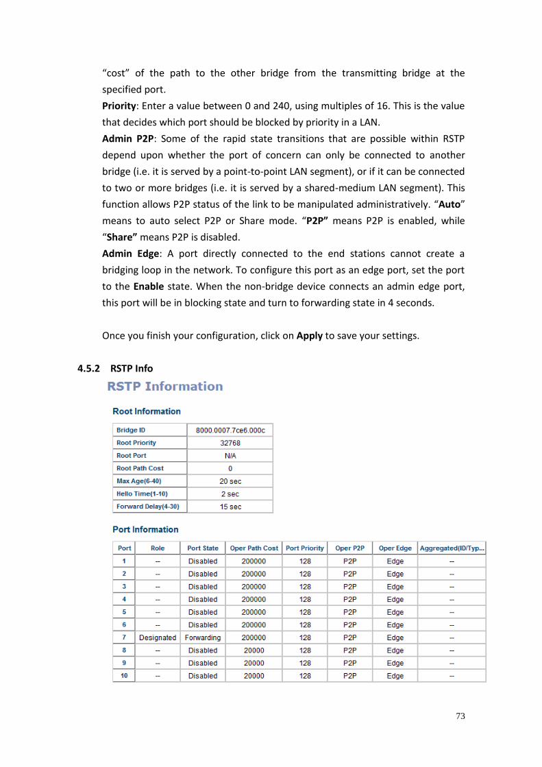
73
“cost” of the path to the other bridge from the transmitting bridge at the
specified port.
Priority: Enter a value between 0 and 240, using multiples of 16. This is the value
that decides which port should be blocked by priority in a LAN.
Admin P2P: Some of the rapid state transitions that are possible within RSTP
depend upon whether the port of concern can only be connected to another
bridge (i.e. it is served by a point-to-point LAN segment), or if it can be connected
to two or more bridges (i.e. it is served by a shared-medium LAN segment). This
function allows P2P status of the link to be manipulated administratively. “Auto”
means to auto select P2P or Share mode. “P2P” means P2P is enabled, while
“Share” means P2P is disabled.
Admin Edge: A port directly connected to the end stations cannot create a
bridging loop in the network. To configure this port as an edge port, set the port
to the Enable state. When the non-bridge device connects an admin edge port,
this port will be in blocking state and turn to forwarding state in 4 seconds.
Once you finish your configuration, click on Apply to save your settings.
4.5.2 RSTP Info
74
This page allows you to see the information of the root switch and port status.
Root Information: You can see root Bridge ID, Root Priority, Root Port, Root Path
Cost and the Max Age, Hello Time and Forward Delay of BPDU sent from the root
switch.
Port Information: You can see port Role, Port State, Path Cost, Port Priority, Oper
P2P mode, Oper edge port mode and Aggregated (ID/Type).
4.5.3 MSTP Configuration
MSTP is the abbreviation of Multiple Spanning Tree Protocol. This protocol is a
direct extension of RSTP. It can provide an independent spanning tree for different
VLANs. It simplifies network management, provides for even faster convergence
than RSTP by limiting the size of each region, and prevents VLAN members from
being segmented from the rest of the group (as sometimes occurs with IEEE
802.1D STP).
While using MSTP, there are some new concepts of network architecture. A switch
may belong to different groups, act as root or designate switch, generate BPDU for
the network to maintain the forwarding table of the spanning tree. With MSTP can
also provide multiple forwarding paths and enable load balancing. Understand the
architecture allows you to maintain the correct spanning tree and operate
effectively.
One VLAN can be mapped to a Multiple Spanning Tree Instance (MSTI). For
example, the maximum Instance we support is usually 16, range from 0-15. The
MSTP builds a separate Multiple Spanning Tree (MST) for each instance to
maintain connectivity among each of the assigned VLAN groups. An Internal
Spanning Tree (IST) is used to connect all the MSTP switches within an MST region.
An MST Region may contain multiple MSTP Instances.
The figure shows there are 2 VLANs/MSTP Instances and each instance has its Root
and forwarding paths.
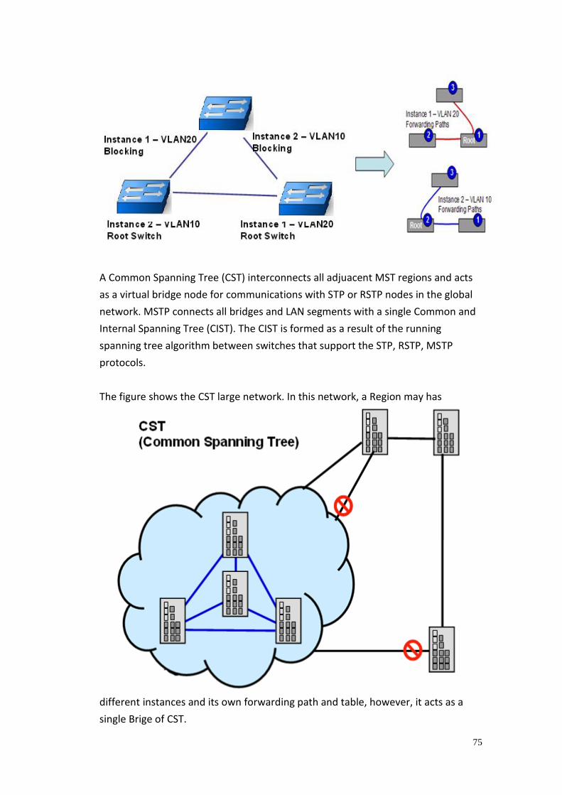
75
A Common Spanning Tree (CST) interconnects all adjuacent MST regions and acts
as a virtual bridge node for communications with STP or RSTP nodes in the global
network. MSTP connects all bridges and LAN segments with a single Common and
Internal Spanning Tree (CIST). The CIST is formed as a result of the running
spanning tree algorithm between switches that support the STP, RSTP, MSTP
protocols.
The figure shows the CST large network. In this network, a Region may has
different instances and its own forwarding path and table, however, it acts as a
single Brige of CST.
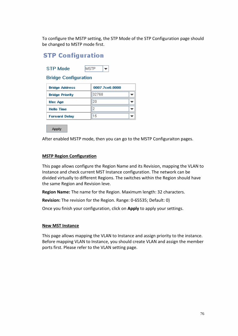
76
To configure the MSTP setting, the STP Mode of the STP Configuration page should be changed to MSTP mode first.
After enabled MSTP mode, then you can go to the MSTP Configuraiton pages.
MSTP Region Configuration
This page allows configure the Region Name and its Revision, mapping the VLAN to Instance and check current MST Instance configuration. The network can be divided virtually to different Regions. The switches within the Region should have the same Region and Revision leve.
Region Name: The name for the Region. Maximum length: 32 characters.
Revision: The revision for the Region. Range: 0-65535; Default: 0)
Once you finish your configuration, click on Apply to apply your settings.
New MST Instance
This page allows mapping the VLAN to Instance and assign priority to the instance. Before mapping VLAN to Instance, you should create VLAN and assign the member ports first. Please refer to the VLAN setting page.
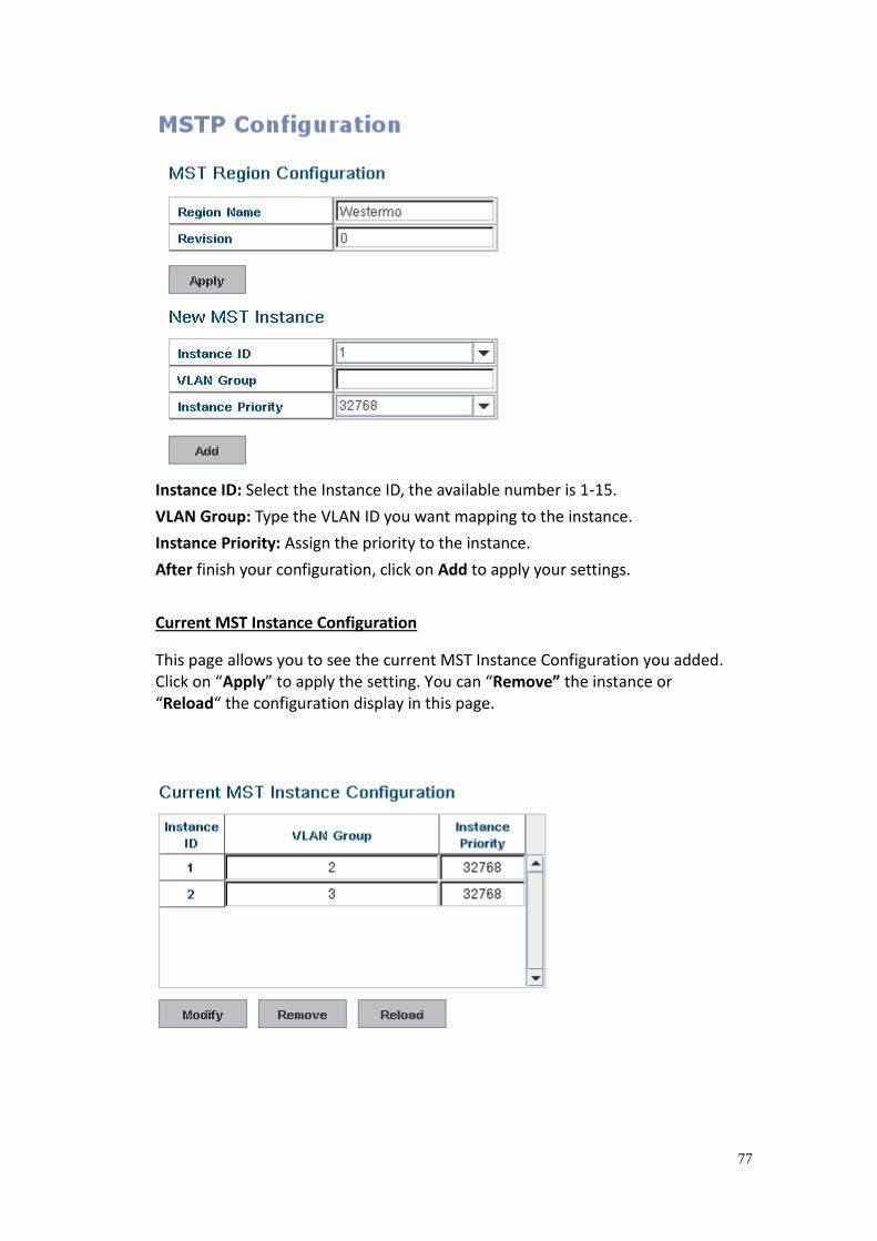
77
Instance ID: Select the Instance ID, the available number is 1-15.
VLAN Group: Type the VLAN ID you want mapping to the instance.
Instance Priority: Assign the priority to the instance.
After finish your configuration, click on Add to apply your settings.
Current MST Instance Configuration
This page allows you to see the current MST Instance Configuration you added. Click on “Apply” to apply the setting. You can “Remove” the instance or “Reload“ the configuration display in this page.
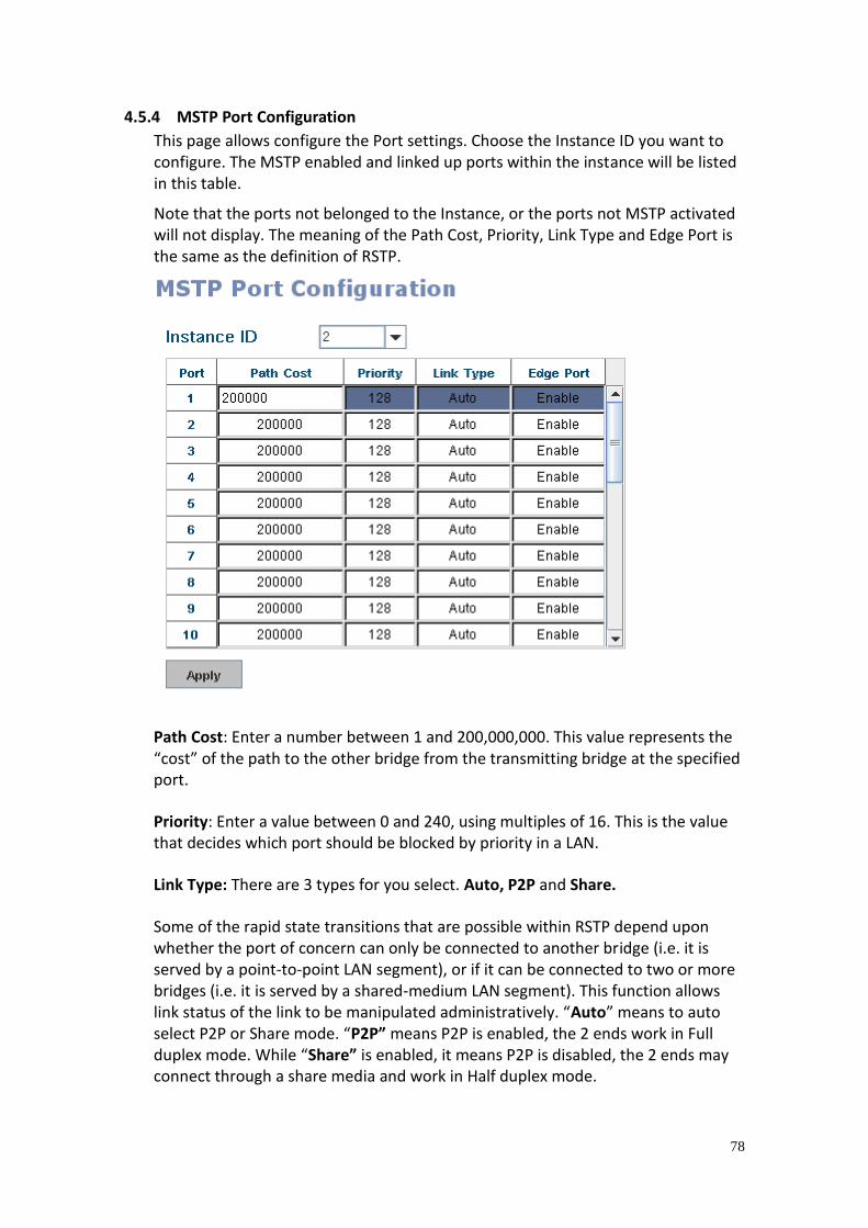
78
4.5.4 MSTP Port Configuration
This page allows configure the Port settings. Choose the Instance ID you want to configure. The MSTP enabled and linked up ports within the instance will be listed in this table.
Note that the ports not belonged to the Instance, or the ports not MSTP activated will not display. The meaning of the Path Cost, Priority, Link Type and Edge Port is the same as the definition of RSTP.
Path Cost: Enter a number between 1 and 200,000,000. This value represents the “cost” of the path to the other bridge from the transmitting bridge at the specified port.
Priority: Enter a value between 0 and 240, using multiples of 16. This is the value that decides which port should be blocked by priority in a LAN.
Link Type: There are 3 types for you select. Auto, P2P and Share.
Some of the rapid state transitions that are possible within RSTP depend upon whether the port of concern can only be connected to another bridge (i.e. it is served by a point-to-point LAN segment), or if it can be connected to two or more bridges (i.e. it is served by a shared-medium LAN segment). This function allows link status of the link to be manipulated administratively. “Auto” means to auto select P2P or Share mode. “P2P” means P2P is enabled, the 2 ends work in Full duplex mode. While “Share” is enabled, it means P2P is disabled, the 2 ends may connect through a share media and work in Half duplex mode.
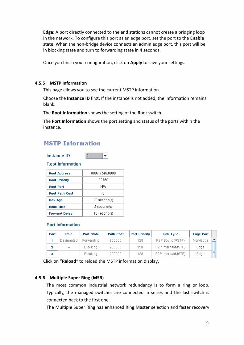
79
Edge: A port directly connected to the end stations cannot create a bridging loop in the network. To configure this port as an edge port, set the port to the Enable state. When the non-bridge device connects an admin edge port, this port will be in blocking state and turn to forwarding state in 4 seconds.
Once you finish your configuration, click on Apply to save your settings.
4.5.5 MSTP Information
This page allows you to see the current MSTP information.
Choose the Instance ID first. If the instance is not added, the information remains blank.
The Root Information shows the setting of the Root switch.
The Port Information shows the port setting and status of the ports within the instance.
Click on “Reload“ to reload the MSTP information display.
4.5.6 Multiple Super Ring (MSR)
The most common industrial network redundancy is to form a ring or loop.
Typically, the managed switches are connected in series and the last switch is
connected back to the first one.
The Multiple Super Ring has enhanced Ring Master selection and faster recovery
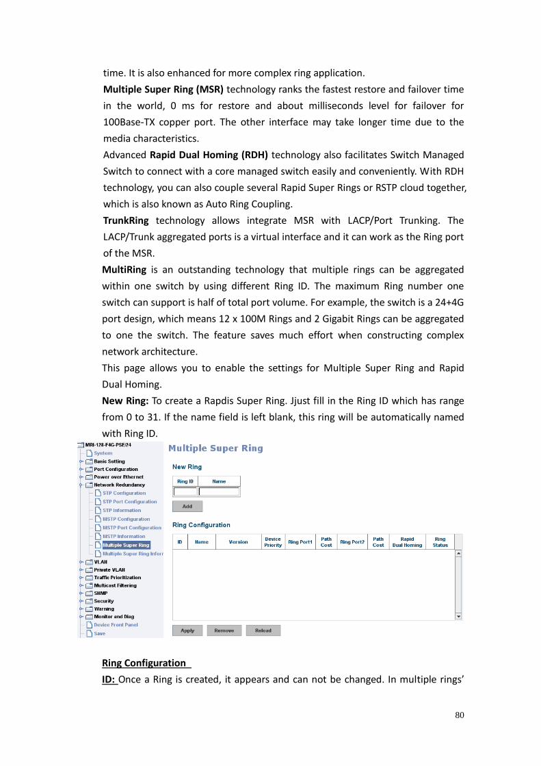
80
time. It is also enhanced for more complex ring application.
Multiple Super Ring (MSR) technology ranks the fastest restore and failover time
in the world, 0 ms for restore and about milliseconds level for failover for
100Base-TX copper port. The other interface may take longer time due to the
media characteristics.
Advanced Rapid Dual Homing (RDH) technology also facilitates Switch Managed
Switch to connect with a core managed switch easily and conveniently. With RDH
technology, you can also couple several Rapid Super Rings or RSTP cloud together,
which is also known as Auto Ring Coupling.
TrunkRing technology allows integrate MSR with LACP/Port Trunking. The
LACP/Trunk aggregated ports is a virtual interface and it can work as the Ring port
of the MSR.
MultiRing is an outstanding technology that multiple rings can be aggregated
within one switch by using different Ring ID. The maximum Ring number one
switch can support is half of total port volume. For example, the switch is a 24+4G
port design, which means 12 x 100M Rings and 2 Gigabit Rings can be aggregated
to one the switch. The feature saves much effort when constructing complex
network architecture.
This page allows you to enable the settings for Multiple Super Ring and Rapid
Dual Homing.
New Ring: To create a Rapdis Super Ring. Jjust fill in the Ring ID which has range
from 0 to 31. If the name field is left blank, this ring will be automatically named
with Ring ID.
Ring Configuration
ID: Once a Ring is created, it appears and can not be changed. In multiple rings’
81
environment, the traffic can only be forwarded under the same ring ID.
Name: This field will show the name of the Ring. If it is not filled in when creating,
it will be automatically named by the rule “RingID”.
Version: The version of Ring can be changed here. There are three modes to
choose: Rapid Super Ring as default.
Device Priority: The switch with highest priority (highest value) will be
automatically selected as Ring Master. Then one of the ring ports in this switch
will become forwarding port and the other one will become blocking port. If all of
the switches have the same priority, the switch with the biggest MAC address will
be selected as Ring Master.
Ring Port1: In Rapid Super Ring environment, you should have 2 Ring Ports. No
matter this switch is Ring Master or not, when configuring RSR, 2 ports should be
selected to be Ring Ports. For Ring Master, one of the ring ports will become the
forwarding port and the other one will become the blocking port.
Path Cost: Change the Path Cost of Ring Port1. If this switch is the Ring Master of
a Ring, then it determines the blocking port. The Port with higher Path Cost in the
two ring Port will become the blocking port, If the Path Cost is the same, the port
with larger port number will become the blocking port.
Ring Port2: Assign another port for ring connection
Path Cost: Change the Path Cost of Ring Port2
Rapid Dual Homing: Rapid Dual Homing is a feature of MSR. When you want to
connect multiple RSR or form a redundant topology with other vendors, RDH
could allow you to have maximum seven multiple links for redundancy without
any problem.
In Rapid Dual Homing, you don’t need to configure specific port to connect to
other protocol. The Rapid Dual Homing will smartly choose the fastest link for
primary link and block all the other links to avoid loop. If the primary link failed,
Rapid Dual Homing will automatically forward the secondary link for network
redandacy. If there are more connections, they will be standby links and recover
one of them if both primary and secondary links are down.
Ring status: To enable/disable the Ring. Please remember to enable the ring after
you add it.
4.5.7 Ring Info
This page shows the RSR information.
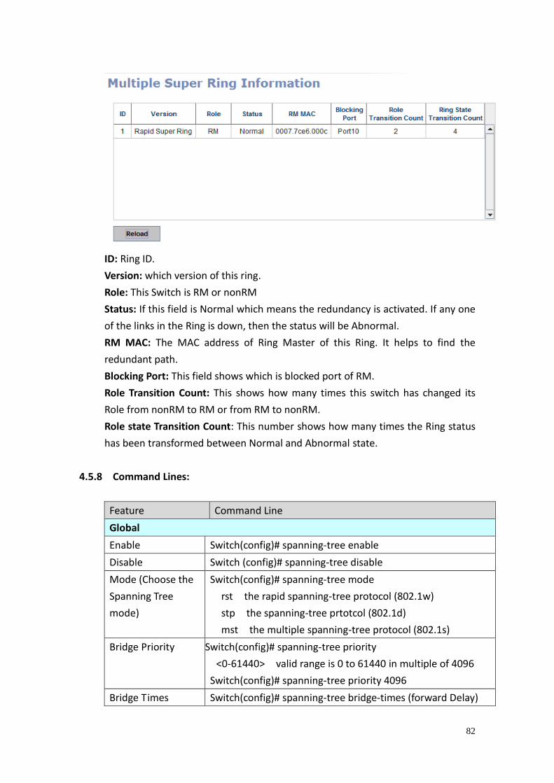
82
ID: Ring ID.
Version: which version of this ring.
Role: This Switch is RM or nonRM
Status: If this field is Normal which means the redundancy is activated. If any one
of the links in the Ring is down, then the status will be Abnormal.
RM MAC: The MAC address of Ring Master of this Ring. It helps to find the
redundant path.
Blocking Port: This field shows which is blocked port of RM.
Role Transition Count: This shows how many times this switch has changed its
Role from nonRM to RM or from RM to nonRM.
Role state Transition Count: This number shows how many times the Ring status
has been transformed between Normal and Abnormal state.
4.5.8 Command Lines:
Feature Command Line
Global
Enable Switch(config)# spanning-tree enable
Disable Switch (config)# spanning-tree disable
Mode (Choose the
Spanning Tree
mode)
Switch(config)# spanning-tree mode
rst the rapid spanning-tree protocol (802.1w)
stp the spanning-tree prtotcol (802.1d)
mst the multiple spanning-tree protocol (802.1s)
Bridge Priority Switch(config)# spanning-tree priority
<0-61440> valid range is 0 to 61440 in multiple of 4096
Switch(config)# spanning-tree priority 4096
Bridge Times Switch(config)# spanning-tree bridge-times (forward Delay)
83
(max-age) (Hello Time)
Switch(config)# spanning-tree bridge-times 15 20 2
This command allows you configure all the timing in one
time.
Forward Delay Switch(config)# spanning-tree forward-time
<4-30> Valid range is 4~30 seconds
Switch(config)# spanning-tree forward-time 15
Max Age Switch(config)# spanning-tree max-age
<6-40> Valid range is 6~40 seconds
Switch(config)# spanning-tree max-age 20
Hello Time Switch(config)# spanning-tree hello-time
<1-10> Valid range is 1~10 seconds
Switch(config)# spanning-tree hello-time 2
MSTP
Enter the MSTP
Configuration Tree
Switch(config)# spanning-tree mst
MSTMAP the mst instance number or range
configuration enter mst configuration mode
forward-time the forwa oreneay time
hello-time the hello time
max-age the message maximum age time
max-hops the maximum hops
sync sync port state of exist vlan entry
Switch(config)# spanning-tree mst configuration
Switch(config)# spanning-tree mst configuration
Switch(config-mst)#
abort exit current mode and discard all changes
end exit current mode, change to enable mode and
apply all changes
exit exit current mode and apply all changes
instance the mst instance
list Print command list
name the name of mst region
no Negate a command or set its defaults
quit exit current mode and apply all changes
revision the revision of mst region
show show mst configuration
Region Region Name:
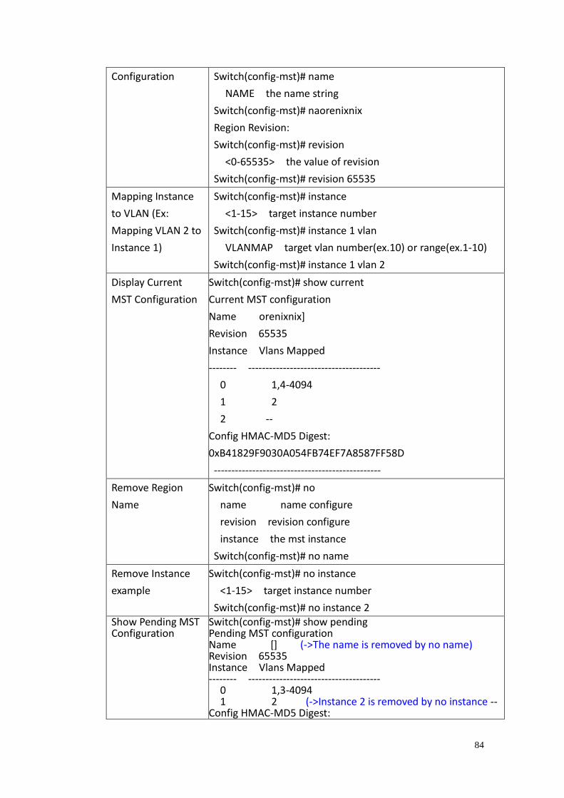
84
Configuration Switch(config-mst)# name
NAME the name string
Switch(config-mst)# na orenixnix
Region Revision:
Switch(config-mst)# revision
<0-65535> the value of revision
Switch(config-mst)# revision 65535
Mapping Instance
to VLAN (Ex:
Mapping VLAN 2 to
Instance 1)
Switch(config-mst)# instance
<1-15> target instance number
Switch(config-mst)# instance 1 vlan
VLANMAP target vlan number(ex.10) or range(ex.1-10)
Switch(config-mst)# instance 1 vlan 2
Display Current
MST Configuration
Switch(config-mst)# show current
Current MST configuration
Name orenixnix]
Revision 65535
Instance Vlans Mapped
-------- --------------------------------------
0 1,4-4094
1 2
2 --
Config HMAC-MD5 Digest:
0xB41829F9030A054FB74EF7A8587FF58D
------------------------------------------------
Remove Region
Name
Switch(config-mst)# no
name name configure
revision revision configure
instance the mst instance
Switch(config-mst)# no name
Remove Instance
example
Switch(config-mst)# no instance
<1-15> target instance number
Switch(config-mst)# no instance 2 Show Pending MST Configuration
Switch(config-mst)# show pending Pending MST configuration Name [] (->The name is removed by no name) Revision 65535 Instance Vlans Mapped -------- -------------------------------------- 0 1,3-4094 1 2 (->Instance 2 is removed by no instance -- Config HMAC-MD5 Digest:
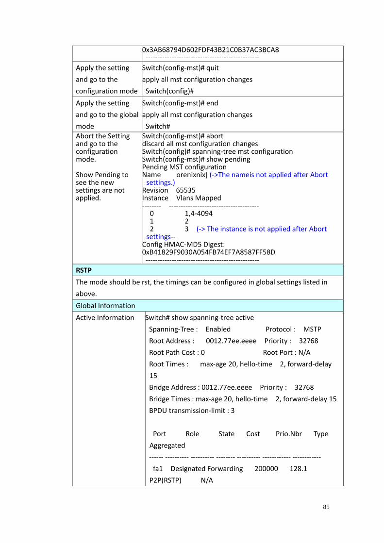
85
0x3AB68794D602FDF43B21C0B37AC3BCA8 ------------------------------------------------
Apply the setting
and go to the
configuration mode
Switch(config-mst)# quit
apply all mst configuration changes
Switch(config)#
Apply the setting
and go to the global
mode
Switch(config-mst)# end
apply all mst configuration changes
Switch# Abort the Setting and go to the configuration mode. Show Pending to see the new settings are not applied.
Switch(config-mst)# abort discard all mst configuration changes Switch(config)# spanning-tree mst configuration Switch(config-mst)# show pending Pending MST configuration Name orenixnix] (->The nameis not applied after Abort
settings.) Revision 65535 Instance Vlans Mapped -------- -------------------------------------- 0 1,4-4094 1 2 2 3 (-> The instance is not applied after Abort
settings-- Config HMAC-MD5 Digest: 0xB41829F9030A054FB74EF7A8587FF58D ------------------------------------------------
RSTP
The mode should be rst, the timings can be configured in global settings listed in
above.
Global Information
Active Information Switch# show spanning-tree active
Spanning-Tree : Enabled Protocol : MSTP
Root Address : 0012.77ee.eeee Priority : 32768
Root Path Cost : 0 Root Port : N/A
Root Times : max-age 20, hello-time 2, forward-delay
15
Bridge Address : 0012.77ee.eeee Priority : 32768
Bridge Times : max-age 20, hello-time 2, forward-delay 15
BPDU transmission-limit : 3
Port Role State Cost Prio.Nbr Type
Aggregated
------ ---------- ---------- -------- ---------- ------------ ------------
fa1 Designated Forwarding 200000 128.1
P2P(RSTP) N/A
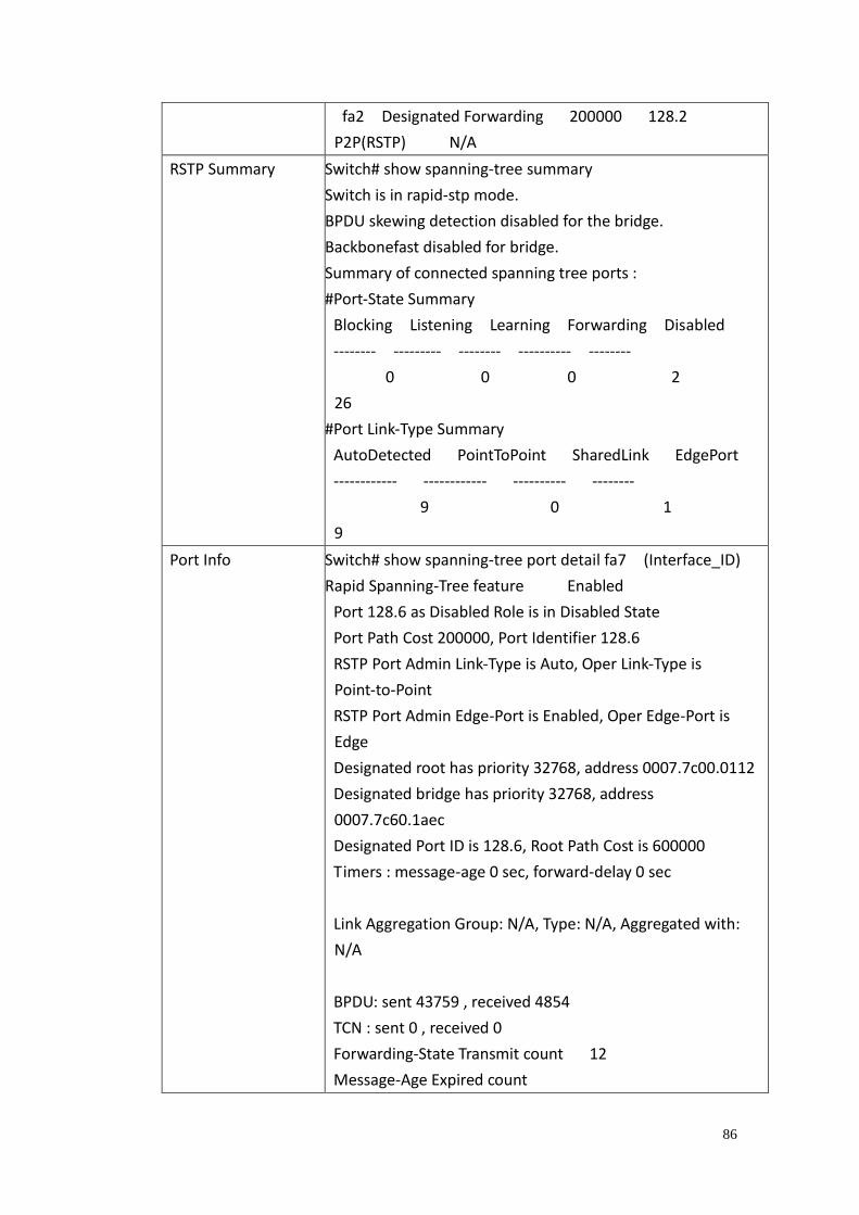
86
fa2 Designated Forwarding 200000 128.2
P2P(RSTP) N/A
RSTP Summary Switch# show spanning-tree summary
Switch is in rapid-stp mode.
BPDU skewing detection disabled for the bridge.
Backbonefast disabled for bridge.
Summary of connected spanning tree ports :
#Port-State Summary
Blocking Listening Learning Forwarding Disabled
-------- --------- -------- ---------- --------
0 0 0 2
26
#Port Link-Type Summary
AutoDetected PointToPoint SharedLink EdgePort
------------ ------------ ---------- --------
9 0 1
9
Port Info Switch# show spanning-tree port detail fa7 (Interface_ID)
Rapid Spanning-Tree feature Enabled
Port 128.6 as Disabled Role is in Disabled State
Port Path Cost 200000, Port Identifier 128.6
RSTP Port Admin Link-Type is Auto, Oper Link-Type is
Point-to-Point
RSTP Port Admin Edge-Port is Enabled, Oper Edge-Port is
Edge
Designated root has priority 32768, address 0007.7c00.0112
Designated bridge has priority 32768, address
0007.7c60.1aec
Designated Port ID is 128.6, Root Path Cost is 600000
Timers : message-age 0 sec, forward-delay 0 sec
Link Aggregation Group: N/A, Type: N/A, Aggregated with:
N/A
BPDU: sent 43759 , received 4854
TCN : sent 0 , received 0
Forwarding-State Transmit count 12
Message-Age Expired count
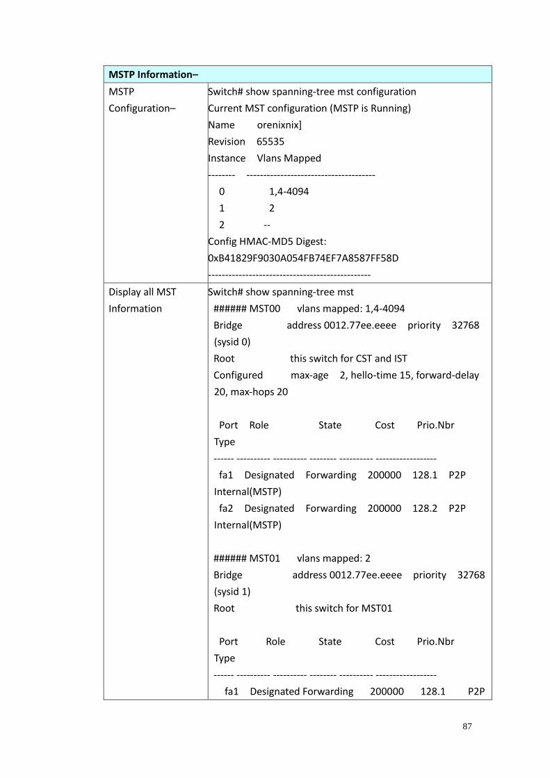
87
MSTP Information–
MSTP
Configuration–
Switch# show spanning-tree mst configuration
Current MST configuration (MSTP is Running)
Name orenixnix]
Revision 65535
Instance Vlans Mapped
-------- --------------------------------------
0 1,4-4094
1 2
2 --
Config HMAC-MD5 Digest:
0xB41829F9030A054FB74EF7A8587FF58D
------------------------------------------------
Display all MST
Information
Switch# show spanning-tree mst
###### MST00 vlans mapped: 1,4-4094
Bridge address 0012.77ee.eeee priority 32768
(sysid 0)
Root this switch for CST and IST
Configured max-age 2, hello-time 15, forward-delay
20, max-hops 20
Port Role State Cost Prio.Nbr
Type
------ ---------- ---------- -------- ---------- ------------------
fa1 Designated Forwarding 200000 128.1 P2P
Internal(MSTP)
fa2 Designated Forwarding 200000 128.2 P2P
Internal(MSTP)
###### MST01 vlans mapped: 2
Bridge address 0012.77ee.eeee priority 32768
(sysid 1)
Root this switch for MST01
Port Role State Cost Prio.Nbr
Type
------ ---------- ---------- -------- ---------- ------------------
fa1 Designated Forwarding 200000 128.1 P2P
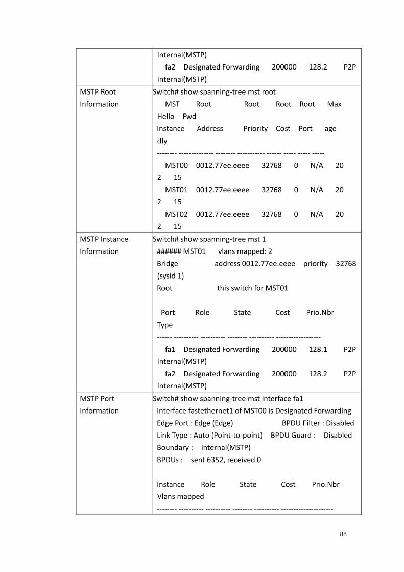
88
Internal(MSTP)
fa2 Designated Forwarding 200000 128.2 P2P
Internal(MSTP)
MSTP Root
Information
Switch# show spanning-tree mst root
MST Root Root Root Root Max
Hello Fwd
Instance Address Priority Cost Port age
dly
-------- -------------- -------- ----------- ------ ----- ----- -----
MST00 0012.77ee.eeee 32768 0 N/A 20
2 15
MST01 0012.77ee.eeee 32768 0 N/A 20
2 15
MST02 0012.77ee.eeee 32768 0 N/A 20
2 15
MSTP Instance
Information
Switch# show spanning-tree mst 1
###### MST01 vlans mapped: 2
Bridge address 0012.77ee.eeee priority 32768
(sysid 1)
Root this switch for MST01
Port Role State Cost Prio.Nbr
Type
------ ---------- ---------- -------- ---------- ------------------
fa1 Designated Forwarding 200000 128.1 P2P
Internal(MSTP)
fa2 Designated Forwarding 200000 128.2 P2P
Internal(MSTP)
MSTP Port
Information
Switch# show spanning-tree mst interface fa1
Interface fastethernet1 of MST00 is Designated Forwarding
Edge Port : Edge (Edge) BPDU Filter : Disabled
Link Type : Auto (Point-to-point) BPDU Guard : Disabled
Boundary : Internal(MSTP)
BPDUs : sent 6352, received 0
Instance Role State Cost Prio.Nbr
Vlans mapped
-------- ---------- ---------- -------- ---------- ---------------------
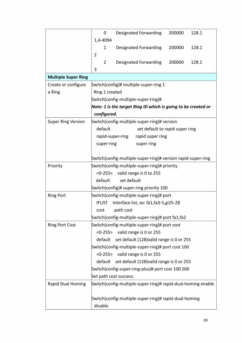
89
0 Designated Forwarding 200000 128.1
1,4-4094
1 Designated Forwarding 200000 128.1
2
2 Designated Forwarding 200000 128.1
3
Multiple Super Ring
Create or configure
a Ring
Switch(config)# multiple-super-ring 1
Ring 1 created
Switch(config-multiple-super-ring)#
Note: 1 is the target Ring ID which is going to be created or
configured.
Super Ring Version Switch(config-multiple-super-ring)# version
default set default to rapid super ring
rapid-super-ring rapid super ring
super-ring super ring
Switch(config-multiple-super-ring)# version rapid-super-ring
Priority Switch(config-multiple-super-ring)# priority
<0-255> valid range is 0 to 255
default set default
Switch(config)# super-ring priority 100
Ring Port Switch(config-multiple-super-ring)# port
IFLIST Interface list, ex: fa1,fa3-5,gi25-28
cost path cost
Switch(config-multiple-super-ring)# port fa1,fa2
Ring Port Cost Switch(config-multiple-super-ring)# port cost
<0-255> valid range is 0 or 255
default set default (128)valid range is 0 or 255
Switch(config-multiple-super-ring)# port cost 100
<0-255> valid range is 0 or 255
default set default (128)valid range is 0 or 255
Switch(config-super-ring-plus)# port cost 100 200
Set path cost success.
Rapid Dual Homing Switch(config-multiple-super-ring)# rapid-dual-homing enable
Switch(config-multiple-super-ring)# rapid-dual-homing
disable
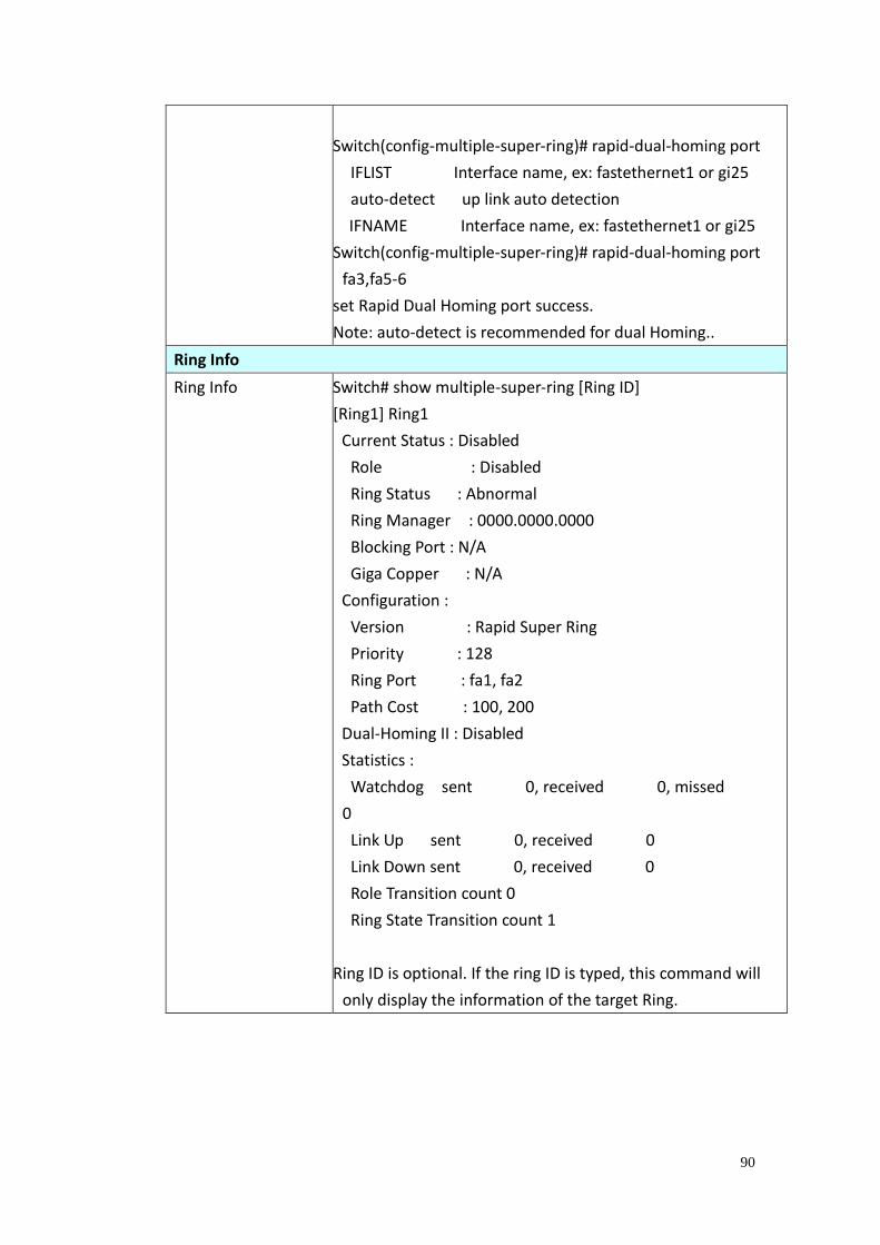
90
Switch(config-multiple-super-ring)# rapid-dual-homing port
IFLIST Interface name, ex: fastethernet1 or gi25
auto-detect up link auto detection
IFNAME Interface name, ex: fastethernet1 or gi25
Switch(config-multiple-super-ring)# rapid-dual-homing port
fa3,fa5-6
set Rapid Dual Homing port success.
Note: auto-detect is recommended for dual Homing..
Ring Info
Ring Info Switch# show multiple-super-ring [Ring ID]
[Ring1] Ring1
Current Status : Disabled
Role : Disabled
Ring Status : Abnormal
Ring Manager : 0000.0000.0000
Blocking Port : N/A
Giga Copper : N/A
Configuration :
Version : Rapid Super Ring
Priority : 128
Ring Port : fa1, fa2
Path Cost : 100, 200
Dual-Homing II : Disabled
Statistics :
Watchdog sent 0, received 0, missed
0
Link Up sent 0, received 0
Link Down sent 0, received 0
Role Transition count 0
Ring State Transition count 1
Ring ID is optional. If the ring ID is typed, this command will
only display the information of the target Ring.
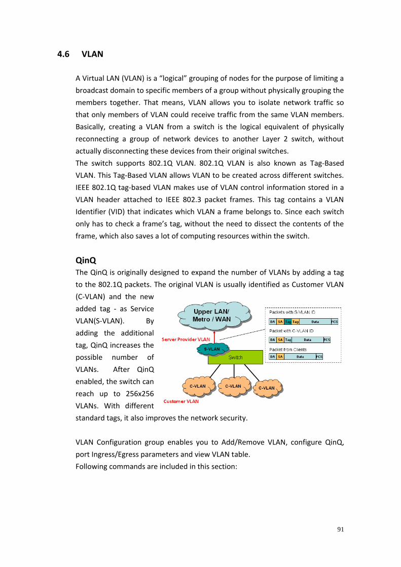
91
4.6 VLAN
A Virtual LAN (VLAN) is a “logical” grouping of nodes for the purpose of limiting a
broadcast domain to specific members of a group without physically grouping the
members together. That means, VLAN allows you to isolate network traffic so
that only members of VLAN could receive traffic from the same VLAN members.
Basically, creating a VLAN from a switch is the logical equivalent of physically
reconnecting a group of network devices to another Layer 2 switch, without
actually disconnecting these devices from their original switches.
The switch supports 802.1Q VLAN. 802.1Q VLAN is also known as Tag-Based
VLAN. This Tag-Based VLAN allows VLAN to be created across different switches.
IEEE 802.1Q tag-based VLAN makes use of VLAN control information stored in a
VLAN header attached to IEEE 802.3 packet frames. This tag contains a VLAN
Identifier (VID) that indicates which VLAN a frame belongs to. Since each switch
only has to check a frame’s tag, without the need to dissect the contents of the
frame, which also saves a lot of computing resources within the switch.
QinQ The QinQ is originally designed to expand the number of VLANs by adding a tag
to the 802.1Q packets. The original VLAN is usually identified as Customer VLAN
(C-VLAN) and the new
added tag - as Service
VLAN(S-VLAN). By
adding the additional
tag, QinQ increases the
possible number of
VLANs. After QinQ
enabled, the switch can
reach up to 256x256
VLANs. With different
standard tags, it also improves the network security.
VLAN Configuration group enables you to Add/Remove VLAN, configure QinQ,
port Ingress/Egress parameters and view VLAN table.
Following commands are included in this section:
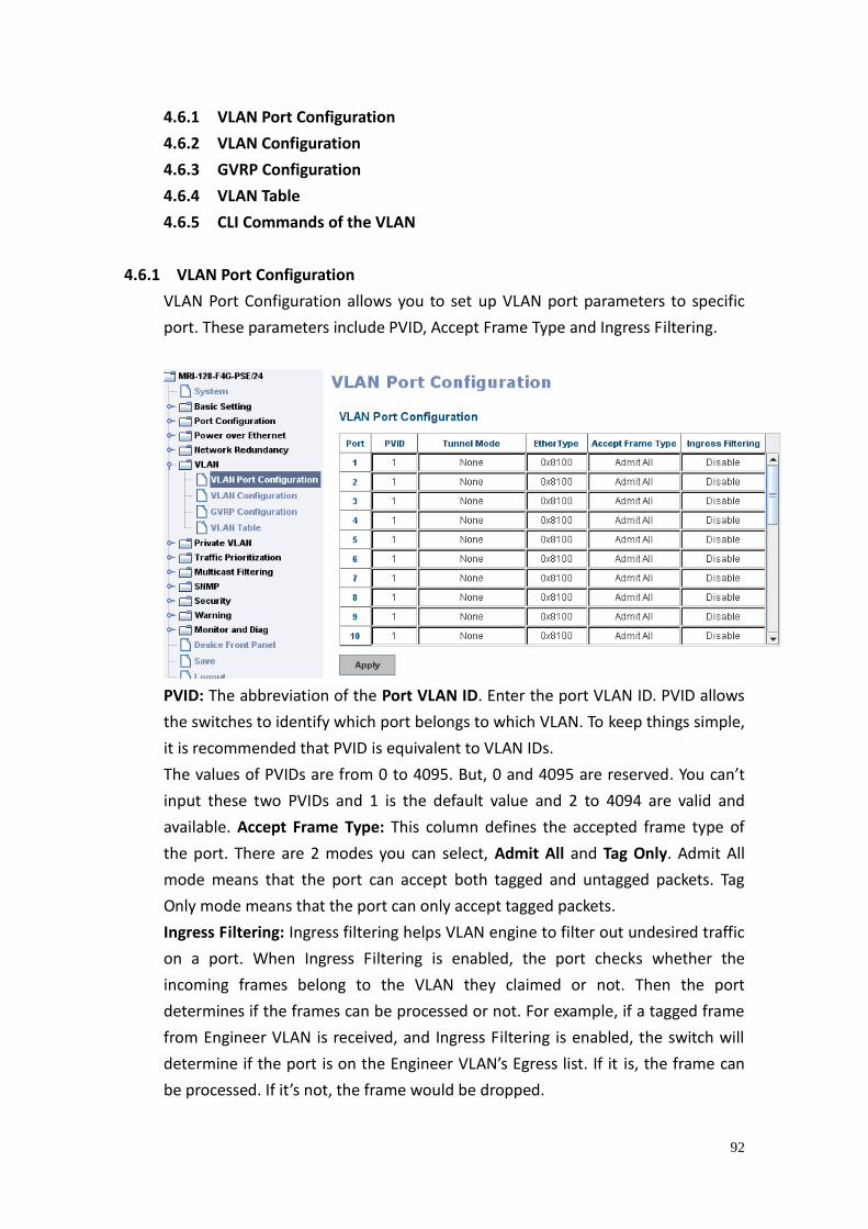
92
4.6.1 VLAN Port Configuration
4.6.2 VLAN Configuration
4.6.3 GVRP Configuration
4.6.4 VLAN Table
4.6.5 CLI Commands of the VLAN
4.6.1 VLAN Port Configuration
VLAN Port Configuration allows you to set up VLAN port parameters to specific
port. These parameters include PVID, Accept Frame Type and Ingress Filtering.
PVID: The abbreviation of the Port VLAN ID. Enter the port VLAN ID. PVID allows
the switches to identify which port belongs to which VLAN. To keep things simple,
it is recommended that PVID is equivalent to VLAN IDs.
The values of PVIDs are from 0 to 4095. But, 0 and 4095 are reserved. You can’t
input these two PVIDs and 1 is the default value and 2 to 4094 are valid and
available. Accept Frame Type: This column defines the accepted frame type of
the port. There are 2 modes you can select, Admit All and Tag Only. Admit All
mode means that the port can accept both tagged and untagged packets. Tag
Only mode means that the port can only accept tagged packets.
Ingress Filtering: Ingress filtering helps VLAN engine to filter out undesired traffic
on a port. When Ingress Filtering is enabled, the port checks whether the
incoming frames belong to the VLAN they claimed or not. Then the port
determines if the frames can be processed or not. For example, if a tagged frame
from Engineer VLAN is received, and Ingress Filtering is enabled, the switch will
determine if the port is on the Engineer VLAN’s Egress list. If it is, the frame can
be processed. If it’s not, the frame would be dropped.
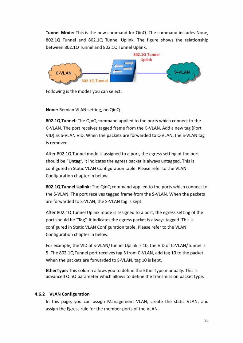
93
Tunnel Mode: This is the new command for QinQ. The command includes None,
802.1Q Tunnel and 802.1Q Tunnel Uplink. The figure shows the relationship
between 802.1Q Tunnel and 802.1Q Tunnel Uplink.
Following is the modes you can select.
None: Remian VLAN setting, no QinQ.
802.1Q Tunnel: The QinQ command applied to the ports which connect to the
C-VLAN. The port receives tagged frame from the C-VLAN. Add a new tag (Port
VID) as S-VLAN VID. When the packets are forwarded to C-VLAN, the S-VLAN tag
is removed.
After 802.1Q Tunnel mode is assigned to a port, the egress setting of the port
should be “Untag”, it indicates the egress packet is always untagged. This is
configured in Static VLAN Configuration table. Please refer to the VLAN
Configuration chapter in below.
802.1Q Tunnel Uplink: The QinQ command applied to the ports which connect to
the S-VLAN. The port receives tagged frame from the S-VLAN. When the packets
are forwarded to S-VLAN, the S-VLAN tag is kept.
After 802.1Q Tunnel Uplink mode is assigned to a port, the egress setting of the
port should be “Tag”, it indicates the egress packet is always tagged. This is
configured in Static VLAN Configuration table. Please refer to the VLAN
Configuration chapter in below.
For example, the VID of S-VLAN/Tunnel Uplink is 10, the VID of C-VLAN/Tunnel is
5. The 802.1Q Tunnel port receives tag 5 from C-VLAN, add tag 10 to the packet.
When the packets are forwarded to S-VLAN, tag 10 is kept.
EtherType: This column allows you to define the EtherType manually. This is advanced QinQ parameter which allows to define the transmission packet type.
4.6.2 VLAN Configuration
In this page, you can assign Management VLAN, create the static VLAN, and
assign the Egress rule for the member ports of the VLAN.
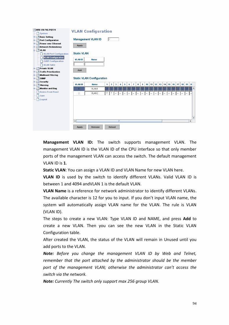
94
Management VLAN ID: The switch supports management VLAN. The
management VLAN ID is the VLAN ID of the CPU interface so that only member
ports of the management VLAN can access the switch. The default management
VLAN ID is 1.
Static VLAN: You can assign a VLAN ID and VLAN Name for new VLAN here.
VLAN ID is used by the switch to identify different VLANs. Valid VLAN ID is
between 1 and 4094 andVLAN 1 is the default VLAN.
VLAN Name is a reference for network administrator to identify different VLANs.
The available character is 12 for you to input. If you don’t input VLAN name, the
system will automatically assign VLAN name for the VLAN. The rule is VLAN
(VLAN ID).
The steps to create a new VLAN: Type VLAN ID and NAME, and press Add to
create a new VLAN. Then you can see the new VLAN in the Static VLAN
Configuration table.
After created the VLAN, the status of the VLAN will remain in Unused until you
add ports to the VLAN.
Note: Before you change the management VLAN ID by Web and Telnet,
remember that the port attached by the administrator should be the member
port of the management VLAN; otherwise the administrator can’t access the
switch via the network.
Note: Currently The switch only support max 256 group VLAN.
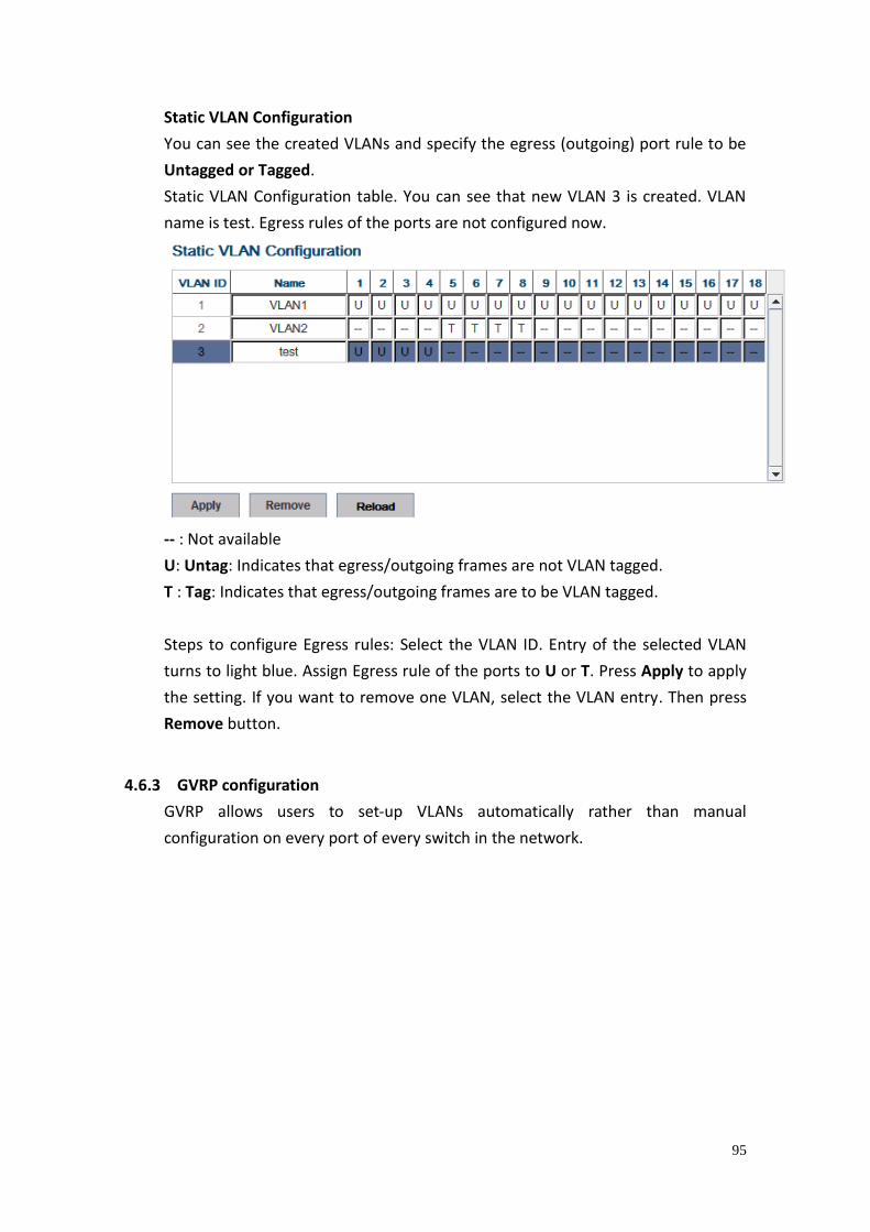
95
Static VLAN Configuration
You can see the created VLANs and specify the egress (outgoing) port rule to be
Untagged or Tagged.
Static VLAN Configuration table. You can see that new VLAN 3 is created. VLAN
name is test. Egress rules of the ports are not configured now.
-- : Not available
U: Untag: Indicates that egress/outgoing frames are not VLAN tagged.
T : Tag: Indicates that egress/outgoing frames are to be VLAN tagged.
Steps to configure Egress rules: Select the VLAN ID. Entry of the selected VLAN
turns to light blue. Assign Egress rule of the ports to U or T. Press Apply to apply
the setting. If you want to remove one VLAN, select the VLAN entry. Then press
Remove button.
4.6.3 GVRP configuration
GVRP allows users to set-up VLANs automatically rather than manual
configuration on every port of every switch in the network.
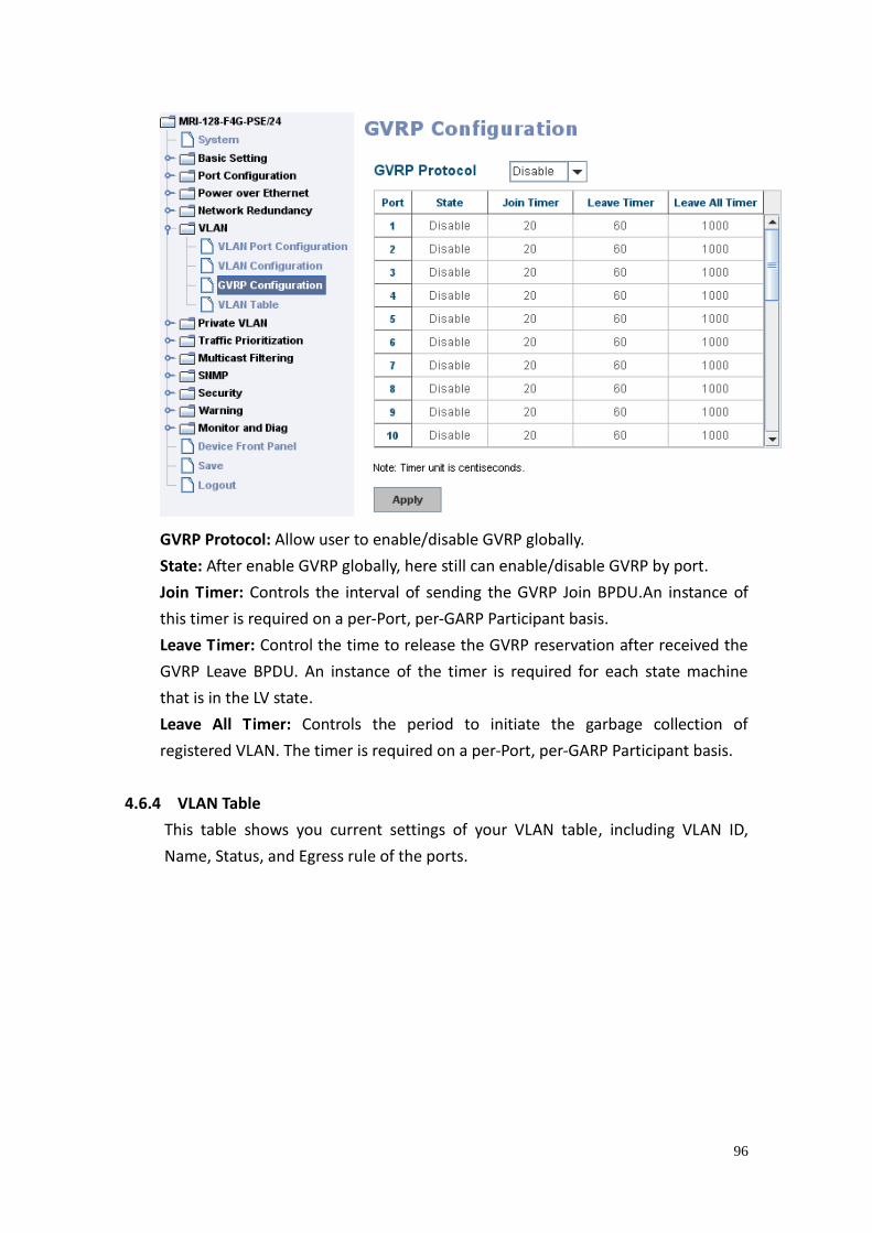
96
GVRP Protocol: Allow user to enable/disable GVRP globally.
State: After enable GVRP globally, here still can enable/disable GVRP by port.
Join Timer: Controls the interval of sending the GVRP Join BPDU.An instance of
this timer is required on a per-Port, per-GARP Participant basis.
Leave Timer: Control the time to release the GVRP reservation after received the
GVRP Leave BPDU. An instance of the timer is required for each state machine
that is in the LV state.
Leave All Timer: Controls the period to initiate the garbage collection of
registered VLAN. The timer is required on a per-Port, per-GARP Participant basis.
4.6.4 VLAN Table
This table shows you current settings of your VLAN table, including VLAN ID,
Name, Status, and Egress rule of the ports.
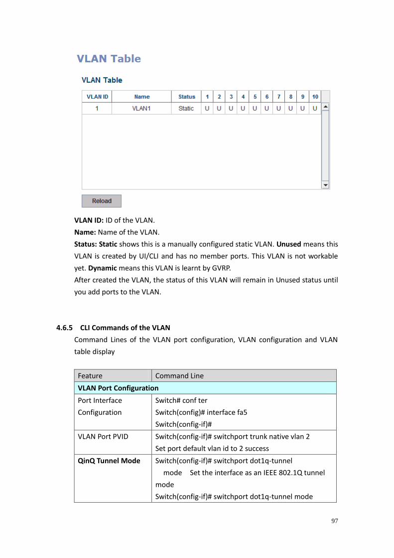
97
VLAN ID: ID of the VLAN.
Name: Name of the VLAN.
Status: Static shows this is a manually configured static VLAN. Unused means this
VLAN is created by UI/CLI and has no member ports. This VLAN is not workable
yet. Dynamic means this VLAN is learnt by GVRP.
After created the VLAN, the status of this VLAN will remain in Unused status until
you add ports to the VLAN.
4.6.5 CLI Commands of the VLAN
Command Lines of the VLAN port configuration, VLAN configuration and VLAN
table display
Feature Command Line
VLAN Port Configuration
Port Interface
Configuration
Switch# conf ter
Switch(config)# interface fa5
Switch(config-if)#
VLAN Port PVID Switch(config-if)# switchport trunk native vlan 2
Set port default vlan id to 2 success
QinQ Tunnel Mode
Switch(config-if)# switchport dot1q-tunnel
mode Set the interface as an IEEE 802.1Q tunnel
mode
Switch(config-if)# switchport dot1q-tunnel mode
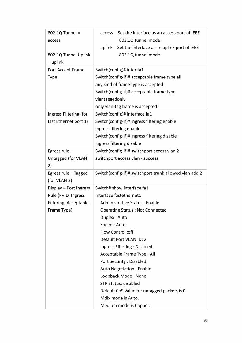
98
802.1Q Tunnel =
access
802.1Q Tunnel Uplink
= uplink
access Set the interface as an access port of IEEE
802.1Q tunnel mode
uplink Set the interface as an uplink port of IEEE
802.1Q tunnel mode
Port Accept Frame
Type
Switch(config)# inter fa1
Switch(config-if)# acceptable frame type all
any kind of frame type is accepted!
Switch(config-if)# acceptable frame type
vlantaggedonly
only vlan-tag frame is accepted!
Ingress Filtering (for
fast Ethernet port 1)
Switch(config)# interface fa1
Switch(config-if)# ingress filtering enable
ingress filtering enable
Switch(config-if)# ingress filtering disable
ingress filtering disable
Egress rule –
Untagged (for VLAN
2)
Switch(config-if)# switchport access vlan 2
switchport access vlan - success
Egress rule – Tagged
(for VLAN 2)
Switch(config-if)# switchport trunk allowed vlan add 2
Display – Port Ingress
Rule (PVID, Ingress
Filtering, Acceptable
Frame Type)
Switch# show interface fa1
Interface fastethernet1
Administrative Status : Enable
Operating Status : Not Connected
Duplex : Auto
Speed : Auto
Flow Control :off
Default Port VLAN ID: 2
Ingress Filtering : Disabled
Acceptable Frame Type : All
Port Security : Disabled
Auto Negotiation : Enable
Loopback Mode : None
STP Status: disabled
Default CoS Value for untagged packets is 0.
Mdix mode is Auto.
Medium mode is Copper.
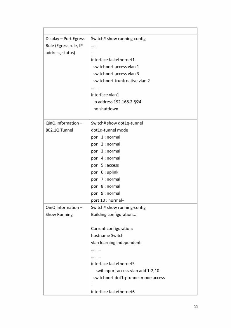
99
Display – Port Egress
Rule (Egress rule, IP
address, status)
Switch# show running-config
……
!
interface fastethernet1
switchport access vlan 1
switchport access vlan 3
switchport trunk native vlan 2
…….
interface vlan1
ip address 192.168.2.8/24
no shutdown
QinQ Information –
802.1Q Tunnel
Switch# show dot1q-tunnel
dot1q-tunnel mode
por 1 : normal
por 2 : normal
por 3 : normal
por 4 : normal
por 5 : access
por 6 : uplink
por 7 : normal
por 8 : normal
por 9 : normal
port 10 : normal–
QinQ Information –
Show Running
Switch# show running-config
Building configuration...
Current configuration:
hostname Switch
vlan learning independent
………
………
interface fastethernet5
switchport access vlan add 1-2,10
switchport dot1q-tunnel mode access
!
interface fastethernet6
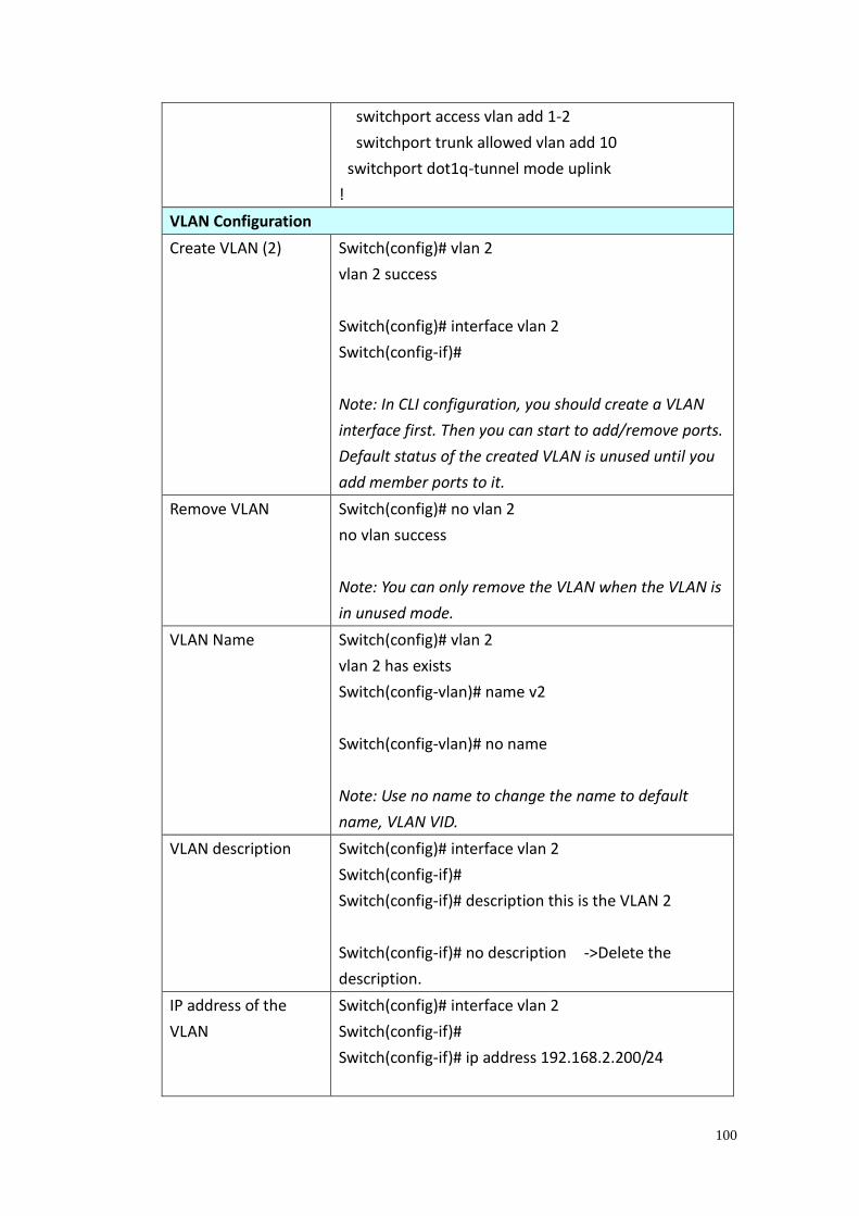
100
switchport access vlan add 1-2
switchport trunk allowed vlan add 10
switchport dot1q-tunnel mode uplink
!
VLAN Configuration
Create VLAN (2) Switch(config)# vlan 2
vlan 2 success
Switch(config)# interface vlan 2
Switch(config-if)#
Note: In CLI configuration, you should create a VLAN
interface first. Then you can start to add/remove ports.
Default status of the created VLAN is unused until you
add member ports to it.
Remove VLAN Switch(config)# no vlan 2
no vlan success
Note: You can only remove the VLAN when the VLAN is
in unused mode.
VLAN Name Switch(config)# vlan 2
vlan 2 has exists
Switch(config-vlan)# name v2
Switch(config-vlan)# no name
Note: Use no name to change the name to default
name, VLAN VID.
VLAN description Switch(config)# interface vlan 2
Switch(config-if)#
Switch(config-if)# description this is the VLAN 2
Switch(config-if)# no description ->Delete the
description.
IP address of the
VLAN
Switch(config)# interface vlan 2
Switch(config-if)#
Switch(config-if)# ip address 192.168.2.200/24
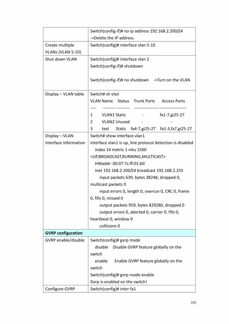
101
Switch(config-if)# no ip address 192.168.2.200/24
->Delete the IP address
Create multiple
VLANs (VLAN 5-10)
Switch(config)# interface vlan 5-10
Shut down VLAN Switch(config)# interface vlan 2
Switch(config-if)# shutdown
Switch(config-if)# no shutdown ->Turn on the VLAN
Display – VLAN table Switch# sh vlan
VLAN Name Status Trunk Ports Access Ports
---- --------- --------- ----------------- -------------------
1 VLAN1 Static - fa1-7,gi25-27
2 VLAN2 Unused - -
3 test Static fa4-7,gi25-27 fa1-3,fa7,gi25-27
Display – VLAN
interface information
Switch# show interface vlan1
interface vlan1 is up, line protocol detection is disabled
index 14 metric 1 mtu 1500
<UP,BROADCAST,RUNNING,MULTICAST>
HWaddr: 00:07:7c:ff:01:b0
inet 192.168.2.200/24 broadcast 192.168.2.255
input packets 639, bytes 38248, dropped 0,
multicast packets 0
input errors 0, length 0, overrun 0, CRC 0, frame
0, fifo 0, missed 0
output packets 959, bytes 829280, dropped 0
output errors 0, aborted 0, carrier 0, fifo 0,
heartbeat 0, window 0
collisions 0
GVRP configuration
GVRP enable/disable Switch(config)# gvrp mode
disable Disable GVRP feature globally on the
switch
enable Enable GVRP feature globally on the
switch
Switch(config)# gvrp mode enable
Gvrp is enabled on the switch!
Configure GVRP Switch(config)# inter fa1
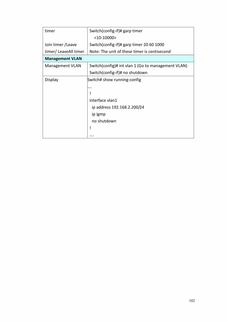
102
timer
Join timer /Leave
timer/ LeaveAll timer
Switch(config-if)# garp timer
<10-10000>
Switch(config-if)# garp timer 20 60 1000
Note: The unit of these timer is centisecond
Management VLAN
Management VLAN Switch(config)# int vlan 1 (Go to management VLAN)
Switch(config-if)# no shutdown
Display Switch# show running-config
….
!
interface vlan1
ip address 192.168.2.200/24
ip igmp
no shutdown
!
….
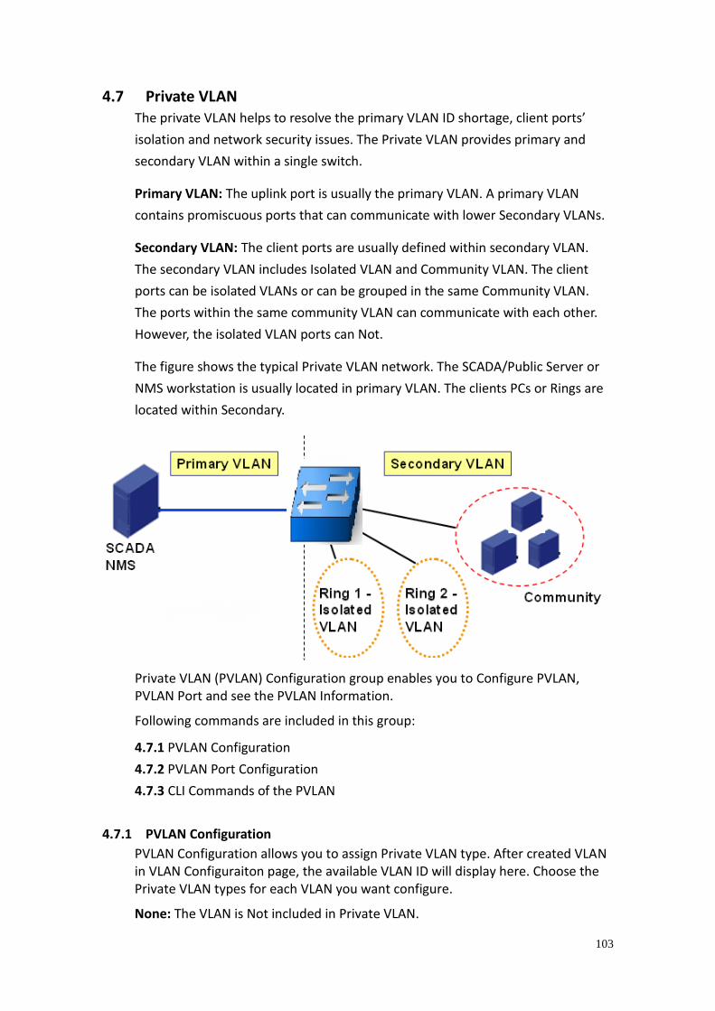
103
4.7 Private VLAN The private VLAN helps to resolve the primary VLAN ID shortage, client ports’
isolation and network security issues. The Private VLAN provides primary and
secondary VLAN within a single switch.
Primary VLAN: The uplink port is usually the primary VLAN. A primary VLAN
contains promiscuous ports that can communicate with lower Secondary VLANs.
Secondary VLAN: The client ports are usually defined within secondary VLAN.
The secondary VLAN includes Isolated VLAN and Community VLAN. The client
ports can be isolated VLANs or can be grouped in the same Community VLAN.
The ports within the same community VLAN can communicate with each other.
However, the isolated VLAN ports can Not.
The figure shows the typical Private VLAN network. The SCADA/Public Server or
NMS workstation is usually located in primary VLAN. The clients PCs or Rings are
located within Secondary.
Private VLAN (PVLAN) Configuration group enables you to Configure PVLAN, PVLAN Port and see the PVLAN Information.
Following commands are included in this group:
4.7.1 PVLAN Configuration
4.7.2 PVLAN Port Configuration
4.7.3 CLI Commands of the PVLAN
4.7.1 PVLAN Configuration
PVLAN Configuration allows you to assign Private VLAN type. After created VLAN in VLAN Configuraiton page, the available VLAN ID will display here. Choose the Private VLAN types for each VLAN you want configure.
None: The VLAN is Not included in Private VLAN.
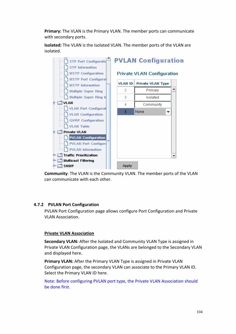
104
Primary: The VLAN is the Primary VLAN. The member ports can communicate with secondary ports.
Isolated: The VLAN is the Isolated VLAN. The member ports of the VLAN are isolated.
Community: The VLAN is the Community VLAN. The member ports of the VLAN can communicate with each other.
4.7.2 PVLAN Port Configuration
PVLAN Port Configuration page allows configure Port Configuration and Private VLAN Association.
Private VLAN Association
Secondary VLAN: After the Isolated and Community VLAN Type is assigned in Private VLAN Configuration page, the VLANs are belonged to the Secondary VLAN and displayed here.
Primary VLAN: After the Primary VLAN Type is assigned in Private VLAN Configuration page, the secondary VLAN can associate to the Primary VLAN ID. Select the Primary VLAN ID here.
Note: Before configuring PVLAN port type, the Private VLAN Association should be done first.
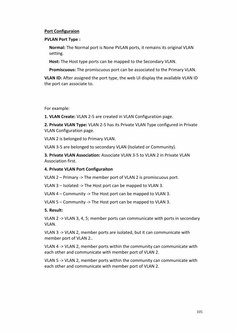
105
Port Configuraion
PVLAN Port Type :
Normal: The Normal port is None PVLAN ports, it remains its original VLAN setting.
Host: The Host type ports can be mapped to the Secondary VLAN.
Promiscuous: The promiscuous port can be associated to the Primary VLAN.
VLAN ID: After assigned the port type, the web UI display the available VLAN ID the port can associate to.
For example:
1. VLAN Create: VLAN 2-5 are created in VLAN Configuration page.
2. Private VLAN Type: VLAN 2-5 has its Private VLAN Type configured in Private VLAN Configuration page.
VLAN 2 is belonged to Primary VLAN.
VLAN 3-5 are belonged to secondary VLAN (Isolated or Community).
3. Private VLAN Association: Associate VLAN 3-5 to VLAN 2 in Private VLAN Association first.
4. Private VLAN Port Configuraiton
VLAN 2 – Primary -> The member port of VLAN 2 is promiscuous port.
VLAN 3 – Isolated -> The Host port can be mapped to VLAN 3.
VLAN 4 – Community -> The Host port can be mapped to VLAN 3.
VLAN 5 – Community -> The Host port can be mapped to VLAN 3.
5. Result:
VLAN 2 -> VLAN 3, 4, 5; member ports can communicate with ports in secondary VLAN.
VLAN 3 -> VLAN 2, member ports are isolated, but it can communicate with member port of VLAN 2..
VLAN 4 -> VLAN 2, member ports within the community can communicate with each other and communicate with member port of VLAN 2.
VLAN 5 -> VLAN 2, member ports within the community can communicate with each other and communicate with member port of VLAN 2.
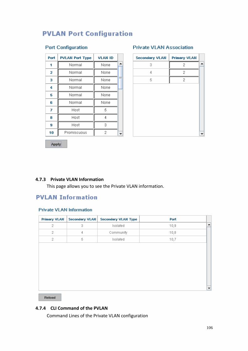
106
4.7.3 Private VLAN Information
This page allows you to see the Private VLAN information.
4.7.4 CLI Command of the PVLAN
Command Lines of the Private VLAN configuration
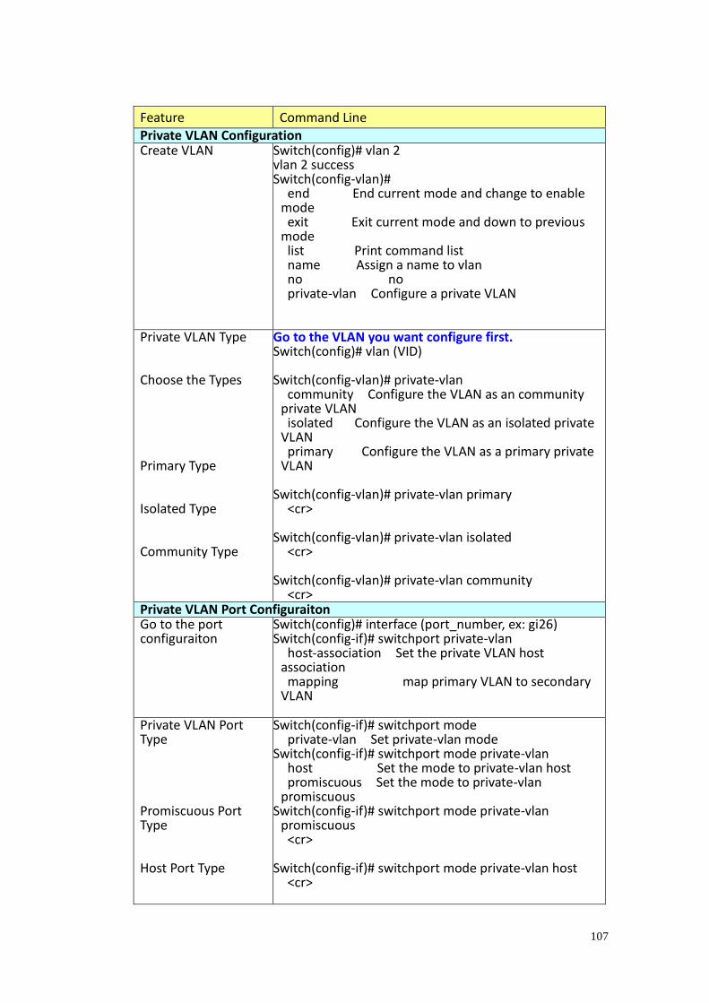
107
Feature Command Line Private VLAN Configuration Create VLAN Switch(config)# vlan 2
vlan 2 success Switch(config-vlan)# end End current mode and change to enable
mode exit Exit current mode and down to previous
mode list Print command list name Assign a name to vlan no no private-vlan Configure a private VLAN
Private VLAN Type Choose the Types Primary Type Isolated Type Community Type
Go to the VLAN you want configure first. Switch(config)# vlan (VID) Switch(config-vlan)# private-vlan community Configure the VLAN as an community
private VLAN isolated Configure the VLAN as an isolated private
VLAN primary Configure the VLAN as a primary private
VLAN Switch(config-vlan)# private-vlan primary <cr> Switch(config-vlan)# private-vlan isolated <cr> Switch(config-vlan)# private-vlan community <cr>
Private VLAN Port Configuraiton Go to the port configuraiton
Switch(config)# interface (port_number, ex: gi26) Switch(config-if)# switchport private-vlan host-association Set the private VLAN host
association mapping map primary VLAN to secondary
VLAN
Private VLAN Port Type Promiscuous Port Type Host Port Type
Switch(config-if)# switchport mode private-vlan Set private-vlan mode Switch(config-if)# switchport mode private-vlan host Set the mode to private-vlan host promiscuous Set the mode to private-vlan
promiscuous Switch(config-if)# switchport mode private-vlan
promiscuous <cr> Switch(config-if)# switchport mode private-vlan host <cr>
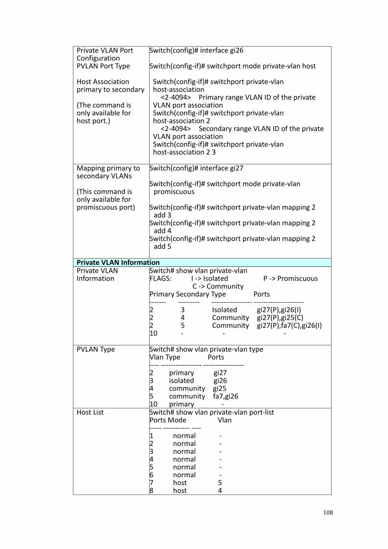
108
Private VLAN Port Configuration PVLAN Port Type Host Association primary to secondary (The command is only available for host port.)
Switch(config)# interface gi26 Switch(config-if)# switchport mode private-vlan host Switch(config-if)# switchport private-vlan host-association <2-4094> Primary range VLAN ID of the private VLAN port association Switch(config-if)# switchport private-vlan host-association 2 <2-4094> Secondary range VLAN ID of the private VLAN port association Switch(config-if)# switchport private-vlan host-association 2 3
Mapping primary to secondary VLANs (This command is only available for promiscuous port)
Switch(config)# interface gi27 Switch(config-if)# switchport mode private-vlan
promiscuous Switch(config-if)# switchport private-vlan mapping 2
add 3 Switch(config-if)# switchport private-vlan mapping 2
add 4 Switch(config-if)# switchport private-vlan mapping 2
add 5
Private VLAN Information Private VLAN Information
Switch# show vlan private-vlan FLAGS: I -> Isolated P -> Promiscuous C -> Community Primary Secondary Type Ports ------- --------- ----------------- --------------------- 2 3 Isolated gi27(P),gi26(I) 2 4 Community gi27(P),gi25(C) 2 5 Community gi27(P),fa7(C),gi26(I) 10 - - -
PVLAN Type Switch# show vlan private-vlan type Vlan Type Ports ---- ----------------- ----------------- 2 primary gi27 3 isolated gi26 4 community gi25 5 community fa7,gi26 10 primary -
Host List Switch# show vlan private-vlan port-list Ports Mode Vlan ----- ----------- ---- 1 normal - 2 normal - 3 normal - 4 normal - 5 normal - 6 normal - 7 host 5 8 host 4
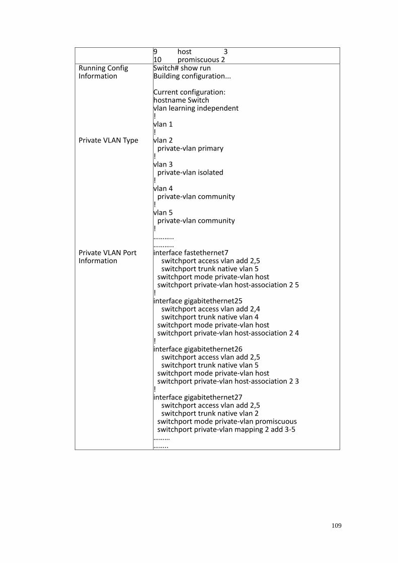
109
9 host 3 10 promiscuous 2
Running Config Information Private VLAN Type Private VLAN Port Information
Switch# show run Building configuration... Current configuration: hostname Switch vlan learning independent ! vlan 1 ! vlan 2 private-vlan primary ! vlan 3 private-vlan isolated ! vlan 4 private-vlan community ! vlan 5 private-vlan community ! ……….. ……….. interface fastethernet7 switchport access vlan add 2,5 switchport trunk native vlan 5 switchport mode private-vlan host switchport private-vlan host-association 2 5 ! interface gigabitethernet25 switchport access vlan add 2,4 switchport trunk native vlan 4 switchport mode private-vlan host switchport private-vlan host-association 2 4 ! interface gigabitethernet26 switchport access vlan add 2,5 switchport trunk native vlan 5 switchport mode private-vlan host switchport private-vlan host-association 2 3 ! interface gigabitethernet27 switchport access vlan add 2,5 switchport trunk native vlan 2 switchport mode private-vlan promiscuous switchport private-vlan mapping 2 add 3-5 ……… ……..
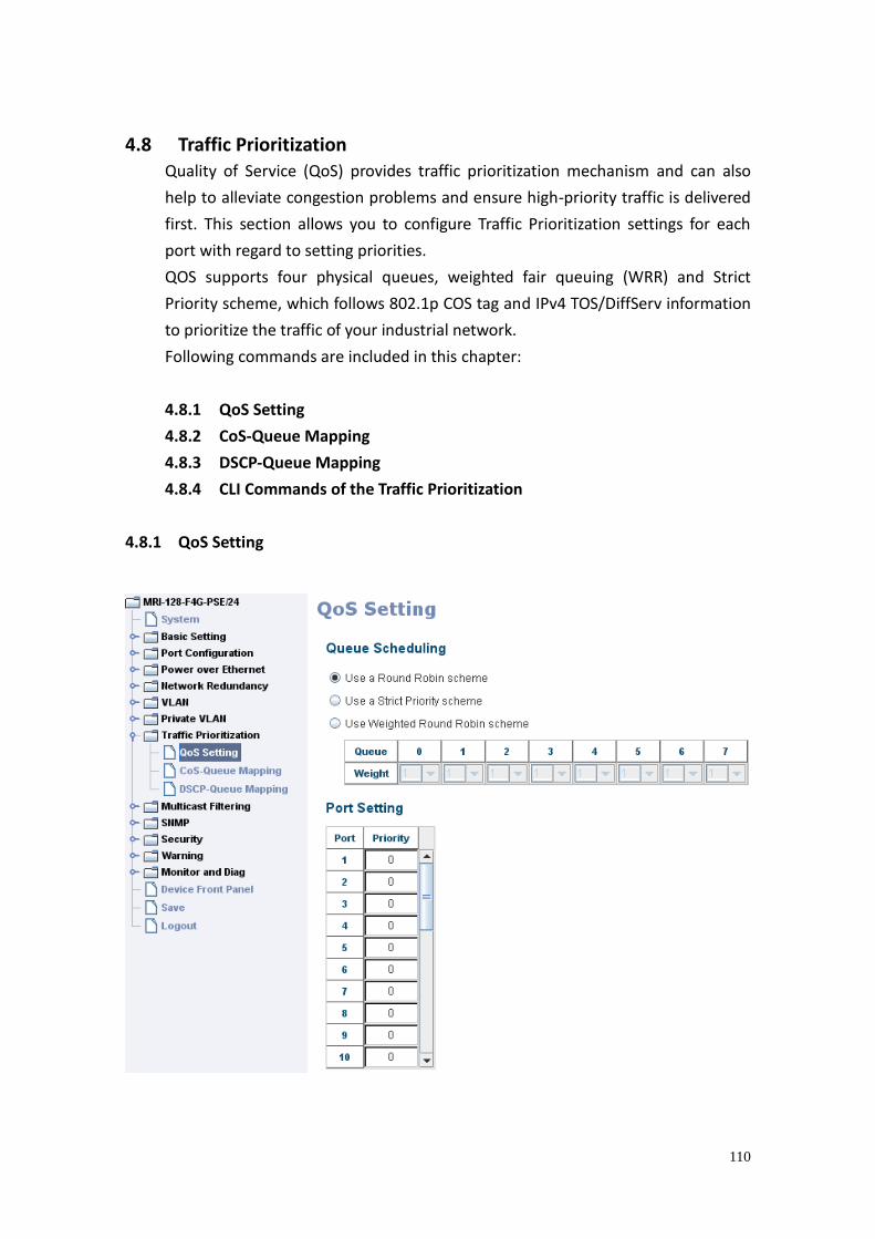
110
4.8 Traffic Prioritization Quality of Service (QoS) provides traffic prioritization mechanism and can also
help to alleviate congestion problems and ensure high-priority traffic is delivered
first. This section allows you to configure Traffic Prioritization settings for each
port with regard to setting priorities.
QOS supports four physical queues, weighted fair queuing (WRR) and Strict
Priority scheme, which follows 802.1p COS tag and IPv4 TOS/DiffServ information
to prioritize the traffic of your industrial network.
Following commands are included in this chapter:
4.8.1 QoS Setting
4.8.2 CoS-Queue Mapping
4.8.3 DSCP-Queue Mapping
4.8.4 CLI Commands of the Traffic Prioritization
4.8.1 QoS Setting
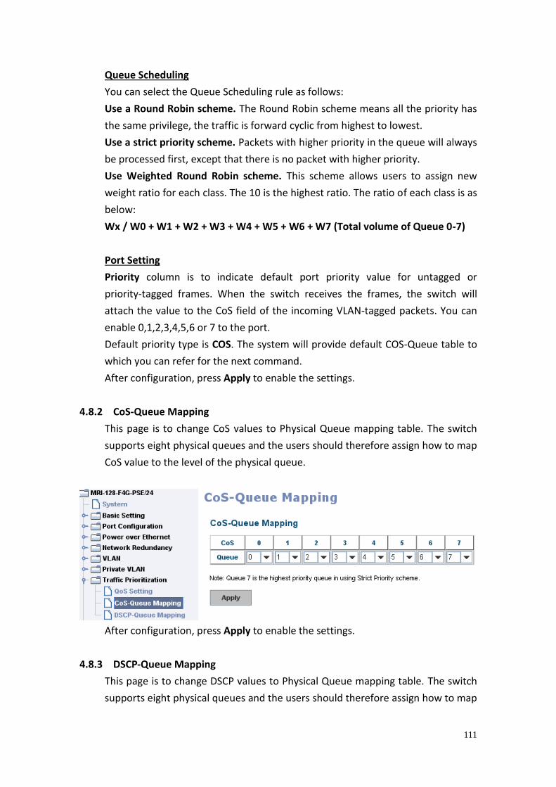
111
Queue Scheduling
You can select the Queue Scheduling rule as follows:
Use a Round Robin scheme. The Round Robin scheme means all the priority has
the same privilege, the traffic is forward cyclic from highest to lowest.
Use a strict priority scheme. Packets with higher priority in the queue will always
be processed first, except that there is no packet with higher priority.
Use Weighted Round Robin scheme. This scheme allows users to assign new
weight ratio for each class. The 10 is the highest ratio. The ratio of each class is as
below:
Wx / W0 + W1 + W2 + W3 + W4 + W5 + W6 + W7 (Total volume of Queue 0-7)
Port Setting
Priority column is to indicate default port priority value for untagged or
priority-tagged frames. When the switch receives the frames, the switch will
attach the value to the CoS field of the incoming VLAN-tagged packets. You can
enable 0,1,2,3,4,5,6 or 7 to the port.
Default priority type is COS. The system will provide default COS-Queue table to
which you can refer for the next command.
After configuration, press Apply to enable the settings.
4.8.2 CoS-Queue Mapping
This page is to change CoS values to Physical Queue mapping table. The switch
supports eight physical queues and the users should therefore assign how to map
CoS value to the level of the physical queue.
After configuration, press Apply to enable the settings.
4.8.3 DSCP-Queue Mapping
This page is to change DSCP values to Physical Queue mapping table. The switch
supports eight physical queues and the users should therefore assign how to map
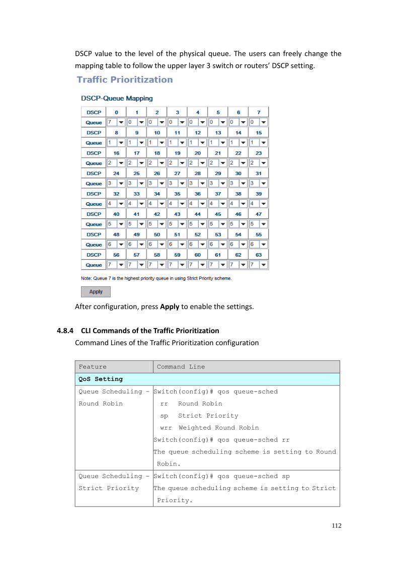
112
DSCP value to the level of the physical queue. The users can freely change the
mapping table to follow the upper layer 3 switch or routers’ DSCP setting.
After configuration, press Apply to enable the settings.
4.8.4 CLI Commands of the Traffic Prioritization
Command Lines of the Traffic Prioritization configuration
Feature Command Line
QoS Setting
Queue Scheduling –
Round Robin
Switch(config)# qos queue-sched
rr Round Robin
sp Strict Priority
wrr Weighted Round Robin
Switch(config)# qos queue-sched rr
The queue scheduling scheme is setting to Round
Robin.
Queue Scheduling –
Strict Priority
Switch(config)# qos queue-sched sp
The queue scheduling scheme is setting to Strict
Priority.
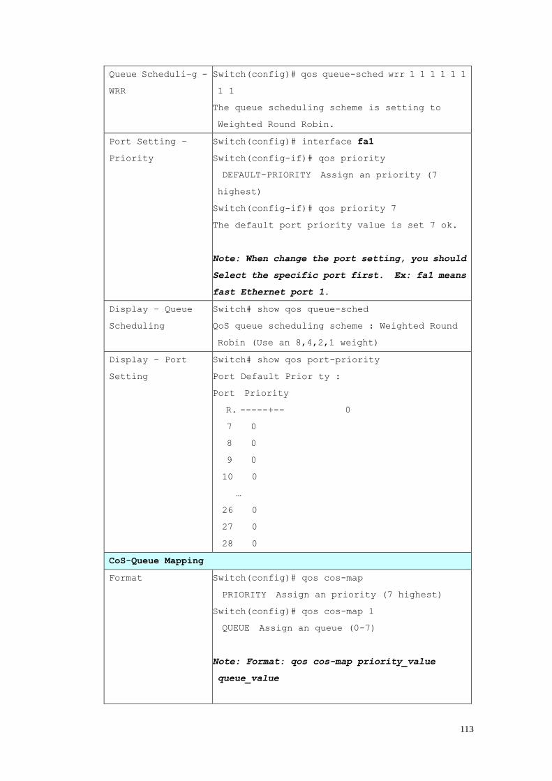
113
Queue Scheduli–g -
WRR
Switch(config)# qos queue-sched wrr 1 1 1 1 1 1
1 1
The queue scheduling scheme is setting to
Weighted Round Robin.
Port Setting –
Priority
Switch(config)# interface fa1
Switch(config-if)# qos priority
DEFAULT-PRIORITY Assign an priority (7
highest)
Switch(config-if)# qos priority 7
The default port priority value is set 7 ok.
Note: When change the port setting, you should
Select the specific port first. Ex: fa1 means
fast Ethernet port 1.
Display – Queue
Scheduling
Switch# show qos queue-sched
QoS queue scheduling scheme : Weighted Round
Robin (Use an 8,4,2,1 weight)
Display – Port
Setting
Switch# show qos port-priority
Port Default Prior ty :
Port Priority
R. -----+-- 0
7 0
8 0
9 0
10 0
…
26 0
27 0
28 0
CoS-Queue Mapping
Format Switch(config)# qos cos-map
PRIORITY Assign an priority (7 highest)
Switch(config)# qos cos-map 1
QUEUE Assign an queue (0-7)
Note: Format: qos cos-map priority_value
queue_value
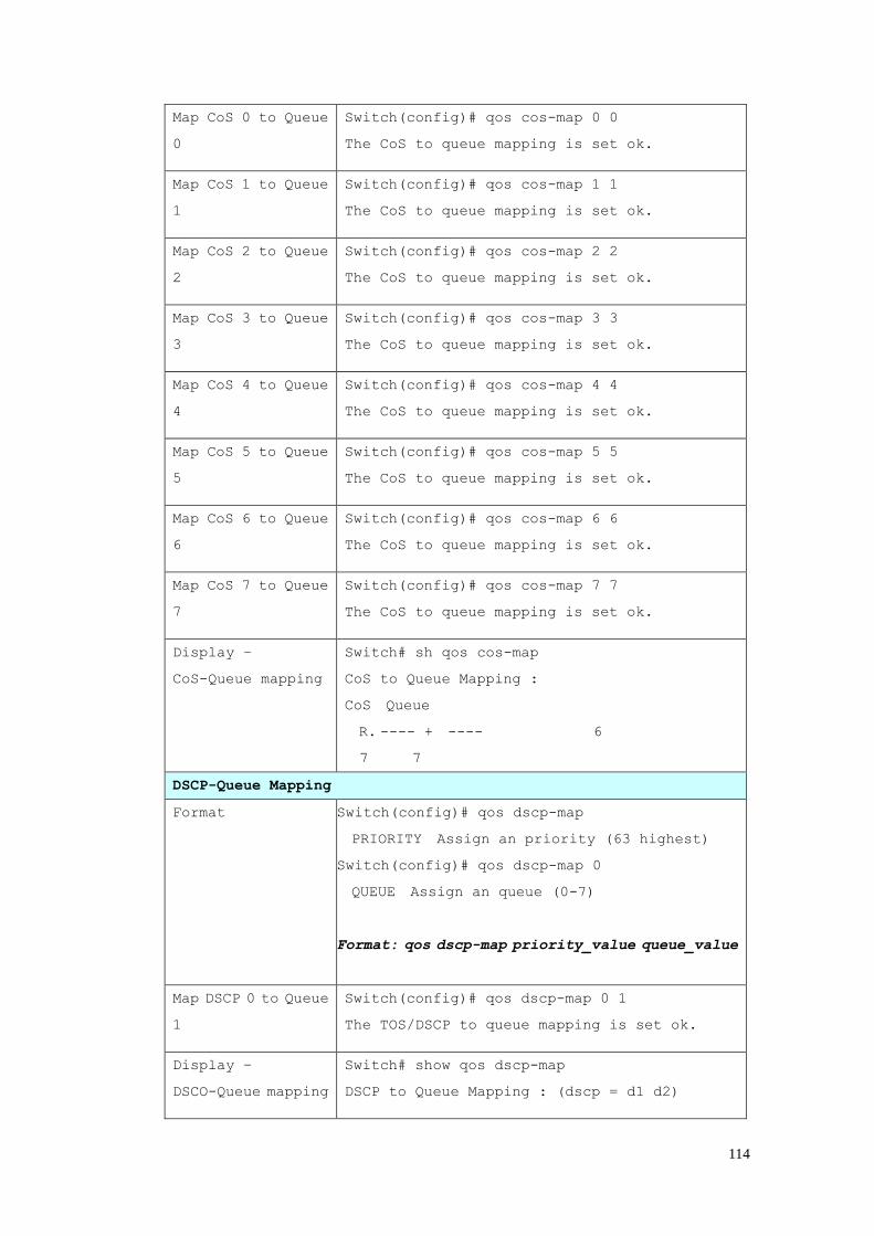
114
Map CoS 0 to Queue
0
Switch(config)# qos cos-map 0 0
The CoS to queue mapping is set ok.
Map CoS 1 to Queue
1
Switch(config)# qos cos-map 1 1
The CoS to queue mapping is set ok.
Map CoS 2 to Queue
2
Switch(config)# qos cos-map 2 2
The CoS to queue mapping is set ok.
Map CoS 3 to Queue
3
Switch(config)# qos cos-map 3 3
The CoS to queue mapping is set ok.
Map CoS 4 to Queue
4
Switch(config)# qos cos-map 4 4
The CoS to queue mapping is set ok.
Map CoS 5 to Queue
5
Switch(config)# qos cos-map 5 5
The CoS to queue mapping is set ok.
Map CoS 6 to Queue
6
Switch(config)# qos cos-map 6 6
The CoS to queue mapping is set ok.
Map CoS 7 to Queue
7
Switch(config)# qos cos-map 7 7
The CoS to queue mapping is set ok.
Display –
CoS-Queue mapping
Switch# sh qos cos-map
CoS to Queue Mapping :
CoS Queue
R. ---- + ---- 6
7 7
DSCP-Queue Mapping
Format Switch(config)# qos dscp-map
PRIORITY Assign an priority (63 highest)
Switch(config)# qos dscp-map 0
QUEUE Assign an queue (0-7)
Format: qos dscp-map priority_value queue_value
Map DSCP 0 to Queue
1
Switch(config)# qos dscp-map 0 1
The TOS/DSCP to queue mapping is set ok.
Display –
DSCO-Queue mapping
Switch# show qos dscp-map
DSCP to Queue Mapping : (dscp = d1 d2)

115
d2| 0 1 2 3 4 5 6 7 8 9
d1 |
-----+----------------------
0 | 0 0 0 0 0 0 0 0 1 1
R. 1 | 1 1 1 1 1 1 2 2 2 2 | 2 2 2 2 3 3 3
3 3 3 | 3 3 4 4 4 4 4 4 4 4 | 5 5 5 5 5
5 5 5 6 5 | 6 6 6 6 6 6 7 7 7 7
6 | 7 7 7 7
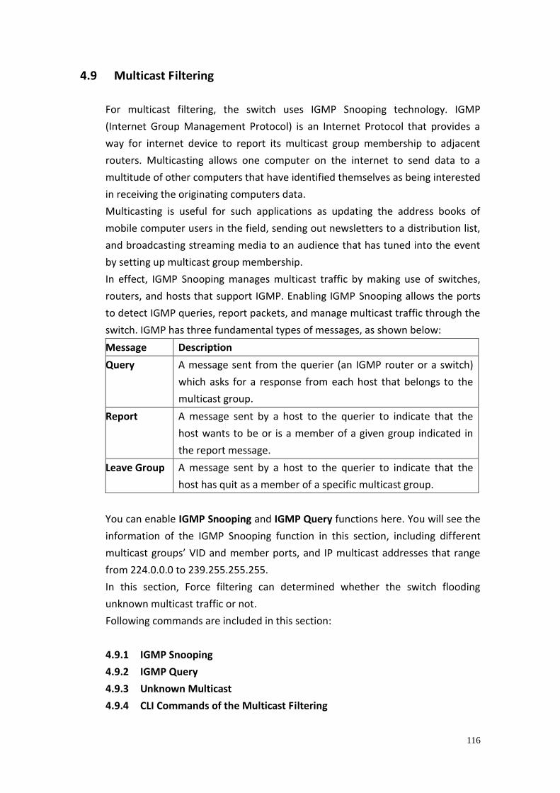
116
4.9 Multicast Filtering
For multicast filtering, the switch uses IGMP Snooping technology. IGMP
(Internet Group Management Protocol) is an Internet Protocol that provides a
way for internet device to report its multicast group membership to adjacent
routers. Multicasting allows one computer on the internet to send data to a
multitude of other computers that have identified themselves as being interested
in receiving the originating computers data.
Multicasting is useful for such applications as updating the address books of
mobile computer users in the field, sending out newsletters to a distribution list,
and broadcasting streaming media to an audience that has tuned into the event
by setting up multicast group membership.
In effect, IGMP Snooping manages multicast traffic by making use of switches,
routers, and hosts that support IGMP. Enabling IGMP Snooping allows the ports
to detect IGMP queries, report packets, and manage multicast traffic through the
switch. IGMP has three fundamental types of messages, as shown below:
Message Description
Query A message sent from the querier (an IGMP router or a switch)
which asks for a response from each host that belongs to the
multicast group.
Report A message sent by a host to the querier to indicate that the
host wants to be or is a member of a given group indicated in
the report message.
Leave Group A message sent by a host to the querier to indicate that the
host has quit as a member of a specific multicast group.
You can enable IGMP Snooping and IGMP Query functions here. You will see the
information of the IGMP Snooping function in this section, including different
multicast groups’ VID and member ports, and IP multicast addresses that range
from 224.0.0.0 to 239.255.255.255.
In this section, Force filtering can determined whether the switch flooding
unknown multicast traffic or not.
Following commands are included in this section:
4.9.1 IGMP Snooping
4.9.2 IGMP Query
4.9.3 Unknown Multicast
4.9.4 CLI Commands of the Multicast Filtering
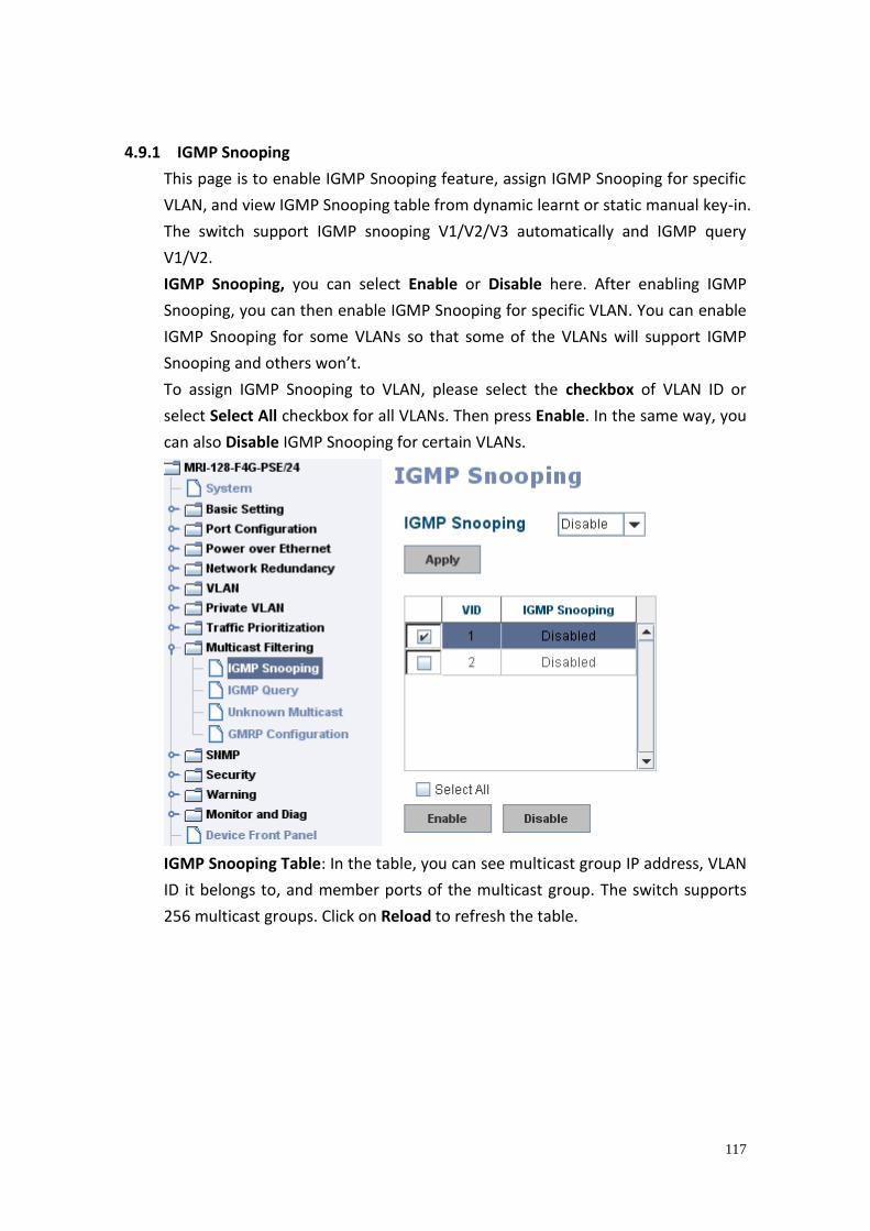
117
4.9.1 IGMP Snooping
This page is to enable IGMP Snooping feature, assign IGMP Snooping for specific
VLAN, and view IGMP Snooping table from dynamic learnt or static manual key-in.
The switch support IGMP snooping V1/V2/V3 automatically and IGMP query
V1/V2.
IGMP Snooping, you can select Enable or Disable here. After enabling IGMP
Snooping, you can then enable IGMP Snooping for specific VLAN. You can enable
IGMP Snooping for some VLANs so that some of the VLANs will support IGMP
Snooping and others won’t.
To assign IGMP Snooping to VLAN, please select the checkbox of VLAN ID or
select Select All checkbox for all VLANs. Then press Enable. In the same way, you
can also Disable IGMP Snooping for certain VLANs.
IGMP Snooping Table: In the table, you can see multicast group IP address, VLAN
ID it belongs to, and member ports of the multicast group. The switch supports
256 multicast groups. Click on Reload to refresh the table.
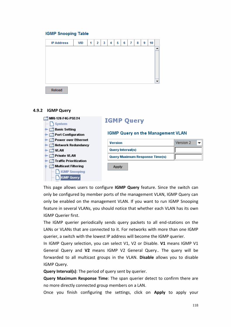
118
4.9.2 IGMP Query
This page allows users to configure IGMP Query feature. Since the switch can
only be configured by member ports of the management VLAN, IGMP Query can
only be enabled on the management VLAN. If you want to run IGMP Snooping
feature in several VLANs, you should notice that whether each VLAN has its own
IGMP Querier first.
The IGMP querier periodically sends query packets to all end-stations on the
LANs or VLANs that are connected to it. For networks with more than one IGMP
querier, a switch with the lowest IP address will become the IGMP querier.
In IGMP Query selection, you can select V1, V2 or Disable. V1 means IGMP V1
General Query and V2 means IGMP V2 General Query.. The query will be
forwarded to all multicast groups in the VLAN. Disable allows you to disable
IGMP Query.
Query Interval(s): The period of query sent by querier.
Query Maximum Response Time: The span querier detect to confirm there are
no more directly connected group members on a LAN.
Once you finish configuring the settings, click on Apply to apply your
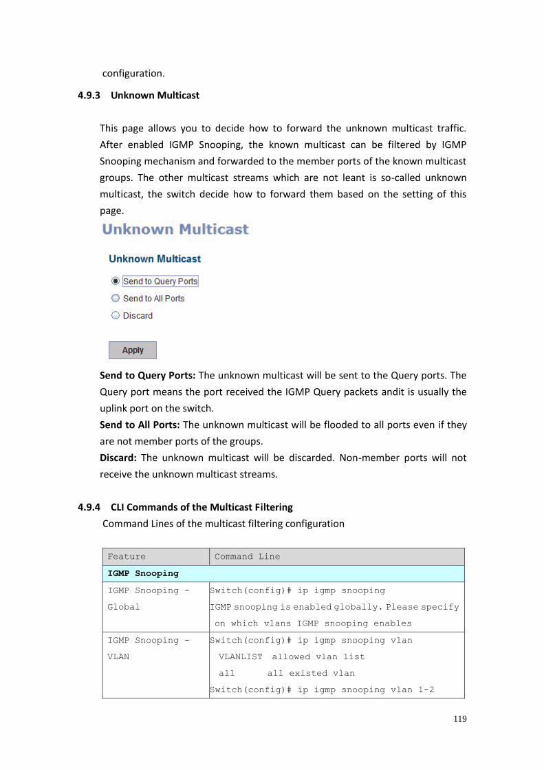
119
configuration.
4.9.3 Unknown Multicast
This page allows you to decide how to forward the unknown multicast traffic.
After enabled IGMP Snooping, the known multicast can be filtered by IGMP
Snooping mechanism and forwarded to the member ports of the known multicast
groups. The other multicast streams which are not leant is so-called unknown
multicast, the switch decide how to forward them based on the setting of this
page.
Send to Query Ports: The unknown multicast will be sent to the Query ports. The
Query port means the port received the IGMP Query packets andit is usually the
uplink port on the switch.
Send to All Ports: The unknown multicast will be flooded to all ports even if they
are not member ports of the groups.
Discard: The unknown multicast will be discarded. Non-member ports will not
receive the unknown multicast streams.
4.9.4 CLI Commands of the Multicast Filtering
Command Lines of the multicast filtering configuration
Feature Command Line
IGMP Snooping
IGMP Snooping -
Global
Switch(config)# ip igmp snooping
IGMP snooping is enabled globally. Please specify
on which vlans IGMP snooping enables
IGMP Snooping -
VLAN
Switch(config)# ip igmp snooping vlan
VLANLIST allowed vlan list
all all existed vlan
Switch(config)# ip igmp snooping vlan 1-2
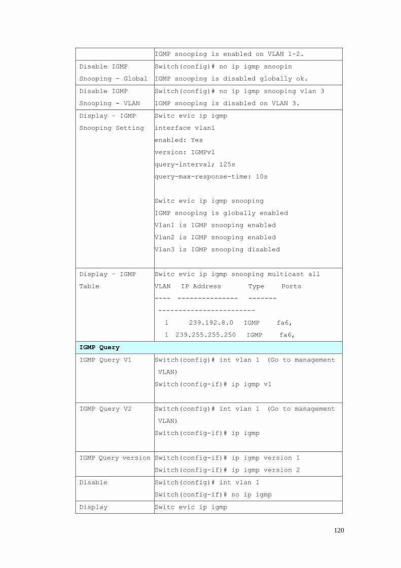
120
IGMP snooping is enabled on VLAN 1-2.
Disable IGMP
Snooping - Global
Switch(config)# no ip igmp snoopin
IGMP snooping is disabled globally ok.
Disable IGMP
Snooping - VLAN
Switch(config)# no ip igmp snooping vlan 3
IGMP snooping is disabled on VLAN 3.
Display – IGMP
Snooping Setting
Switc evic ip igmp
interface vlan1
enabled: Yes
version: IGMPv1
query-interval; 125s
query-max-response-time: 10s
Switc evic ip igmp snooping
IGMP snooping is globally enabled
Vlan1 is IGMP snooping enabled
Vlan2 is IGMP snooping enabled
Vlan3 is IGMP snooping disabled
Display – IGMP
Table
Switc evic ip igmp snooping multicast all
VLAN IP Address Type Ports
---- --------------- -------
------------------------
1 239.192.8.0 IGMP fa6,
1 239.255.255.250 IGMP fa6,
IGMP Query
IGMP Query V1 Switch(config)# int vlan 1 (Go to management
VLAN)
Switch(config-if)# ip igmp v1
IGMP Query V2 Switch(config)# int vlan 1 (Go to management
VLAN)
Switch(config-if)# ip igmp
IGMP Query version Switch(config-if)# ip igmp version 1
Switch(config-if)# ip igmp version 2
Disable Switch(config)# int vlan 1
Switch(config-if)# no ip igmp
Display Switc evic ip igmp
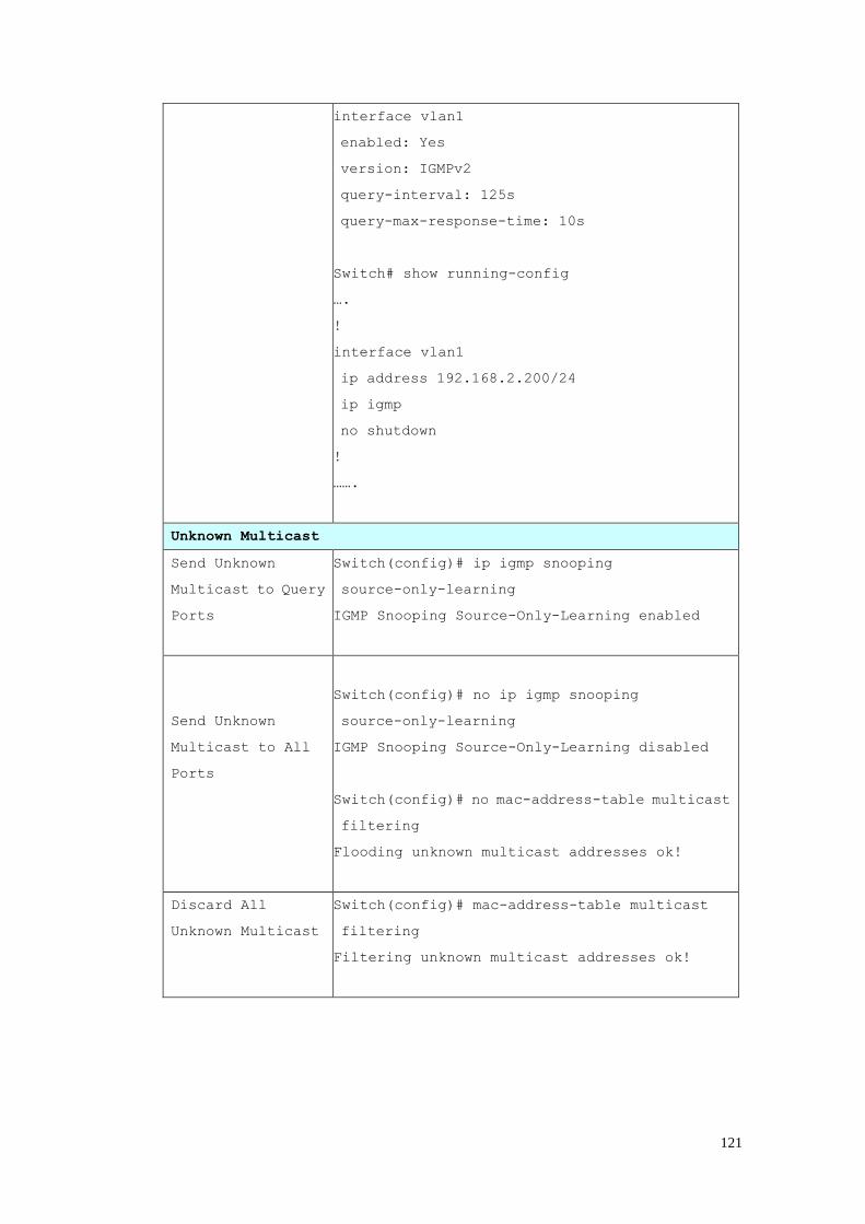
121
interface vlan1
enabled: Yes
version: IGMPv2
query-interval: 125s
query-max-response-time: 10s
Switch# show running-config
….
!
interface vlan1
ip address 192.168.2.200/24
ip igmp
no shutdown
!
…….
Unknown Multicast
Send Unknown
Multicast to Query
Ports
Switch(config)# ip igmp snooping
source-only-learning
IGMP Snooping Source-Only-Learning enabled
Send Unknown
Multicast to All
Ports
Switch(config)# no ip igmp snooping
source-only-learning
IGMP Snooping Source-Only-Learning disabled
Switch(config)# no mac-address-table multicast
filtering
Flooding unknown multicast addresses ok!
Discard All
Unknown Multicast
Switch(config)# mac-address-table multicast
filtering
Filtering unknown multicast addresses ok!
122
4.10 SNMP Simple Network Management Protocol (SNMP) is a protocol used for exchanging
management information between network devices and is a member of the
TCP/IP protocol suite. The switch support SNMP v1 and v2c and V3.
An SNMP managed network consists of two main components: agents and a
manager. An agent is a management software module that resides in a managed
switch. An agent translates the local management information from the managed
device into a SNMP compatible format. The manager is the console through the
network.
Following commands are included in this chapter:
4.10.1 SNMP Configuration
4.10.2 SNMPv3 Profile
4.10.3 SNMP Traps
4.10.4 SNMP CLI Commands for SNMP
4.10.1 SNMP Configuration
This page allows users to configure SNMP V1/V2c Community. The community
string can be viewed as the password because SNMP V1/V2c doesn’t request you
to enter password before you try to access SNMP agent.
The community includes two privileges, Read Only and Read and Write.
With Read Only privilege, you only have the ability to read the values of MIB
tables. Default community string is Public.
With Read and Write privilege, you have the ability to read and set the values of
MIB tables. Default community string is Private.
The switch allows users to assign four community strings. Type the community
string and select the privilege andthen press Apply.
Note: When you first install the device in your network, we highly recommend you
to change the community string. Since most SNMP management application uses
Public and Private as their default community name, this might be the leakage of
the network security.
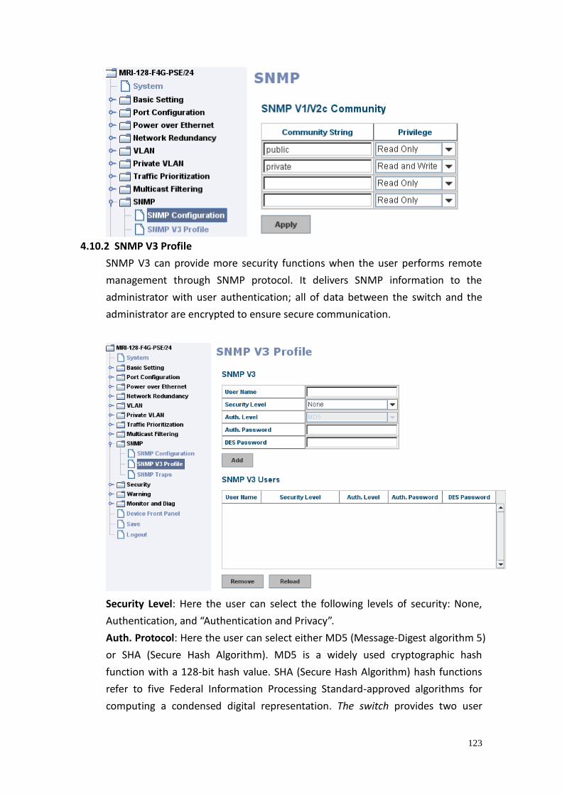
123
4.10.2 SNMP V3 Profile
SNMP V3 can provide more security functions when the user performs remote
management through SNMP protocol. It delivers SNMP information to the
administrator with user authentication; all of data between the switch and the
administrator are encrypted to ensure secure communication.
Security Level: Here the user can select the following levels of security: None,
Authentication, and “Authentication and Privacy”.
Auth. Protocol: Here the user can select either MD5 (Message-Digest algorithm 5)
or SHA (Secure Hash Algorithm). MD5 is a widely used cryptographic hash
function with a 128-bit hash value. SHA (Secure Hash Algorithm) hash functions
refer to five Federal Information Processing Standard-approved algorithms for
computing a condensed digital representation. The switch provides two user
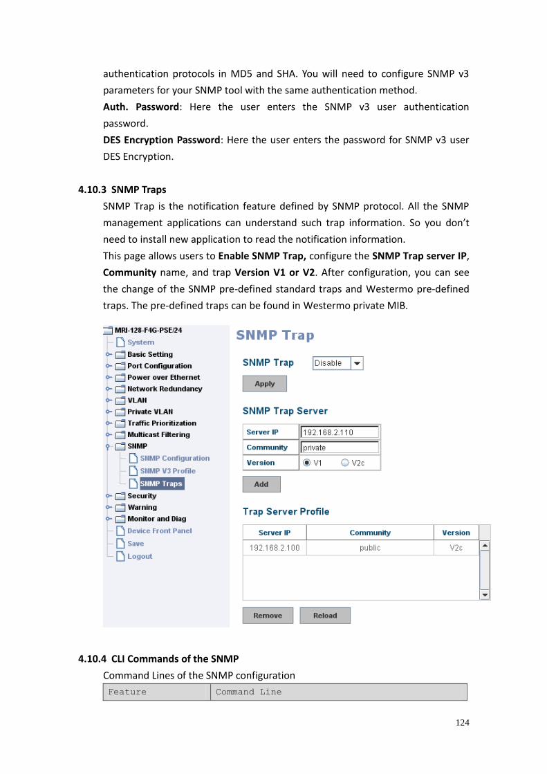
124
authentication protocols in MD5 and SHA. You will need to configure SNMP v3
parameters for your SNMP tool with the same authentication method.
Auth. Password: Here the user enters the SNMP v3 user authentication
password.
DES Encryption Password: Here the user enters the password for SNMP v3 user
DES Encryption.
4.10.3 SNMP Traps
SNMP Trap is the notification feature defined by SNMP protocol. All the SNMP
management applications can understand such trap information. So you don’t
need to install new application to read the notification information.
This page allows users to Enable SNMP Trap, configure the SNMP Trap server IP,
Community name, and trap Version V1 or V2. After configuration, you can see
the change of the SNMP pre-defined standard traps and Westermo pre-defined
traps. The pre-defined traps can be found in Westermo private MIB.
4.10.4 CLI Commands of the SNMP
Command Lines of the SNMP configuration
Feature Command Line
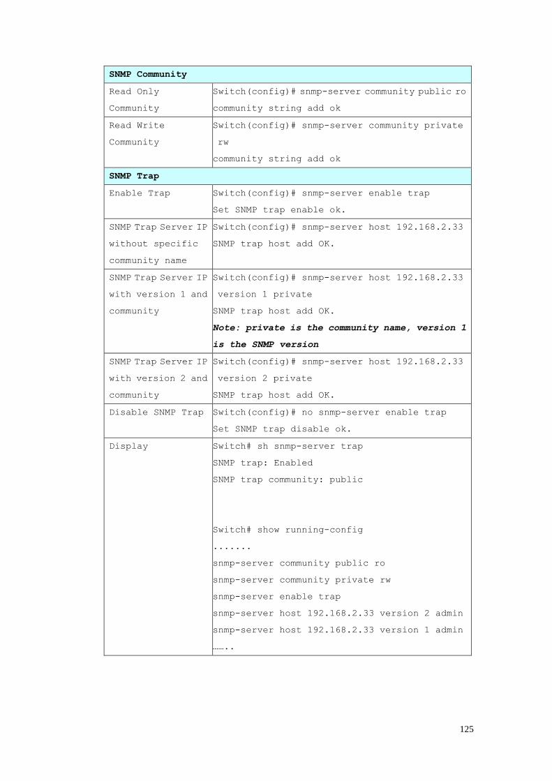
125
SNMP Community
Read Only
Community
Switch(config)# snmp-server community public ro
community string add ok
Read Write
Community
Switch(config)# snmp-server community private
rw
community string add ok
SNMP Trap
Enable Trap Switch(config)# snmp-server enable trap
Set SNMP trap enable ok.
SNMP Trap Server IP
without specific
community name
Switch(config)# snmp-server host 192.168.2.33
SNMP trap host add OK.
SNMP Trap Server IP
with version 1 and
community
Switch(config)# snmp-server host 192.168.2.33
version 1 private
SNMP trap host add OK.
Note: private is the community name, version 1
is the SNMP version
SNMP Trap Server IP
with version 2 and
community
Switch(config)# snmp-server host 192.168.2.33
version 2 private
SNMP trap host add OK.
Disable SNMP Trap Switch(config)# no snmp-server enable trap
Set SNMP trap disable ok.
Display Switch# sh snmp-server trap
SNMP trap: Enabled
SNMP trap community: public
Switch# show running-config
.......
snmp-server community public ro
snmp-server community private rw
snmp-server enable trap
snmp-server host 192.168.2.33 version 2 admin
snmp-server host 192.168.2.33 version 1 admin
……..
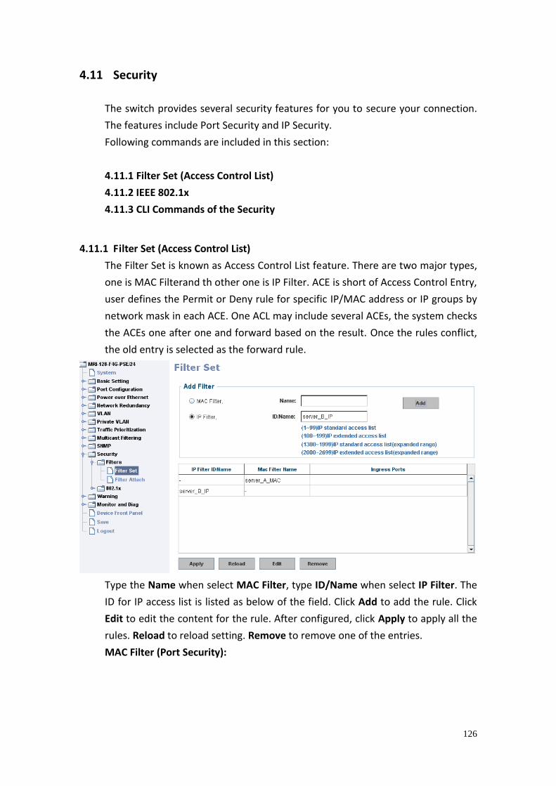
126
4.11 Security
The switch provides several security features for you to secure your connection.
The features include Port Security and IP Security.
Following commands are included in this section:
4.11.1 Filter Set (Access Control List)
4.11.2 IEEE 802.1x
4.11.3 CLI Commands of the Security
4.11.1 Filter Set (Access Control List)
The Filter Set is known as Access Control List feature. There are two major types,
one is MAC Filterand th other one is IP Filter. ACE is short of Access Control Entry,
user defines the Permit or Deny rule for specific IP/MAC address or IP groups by
network mask in each ACE. One ACL may include several ACEs, the system checks
the ACEs one after one and forward based on the result. Once the rules conflict,
the old entry is selected as the forward rule.
Type the Name when select MAC Filter, type ID/Name when select IP Filter. The
ID for IP access list is listed as below of the field. Click Add to add the rule. Click
Edit to edit the content for the rule. After configured, click Apply to apply all the
rules. Reload to reload setting. Remove to remove one of the entries.
MAC Filter (Port Security):
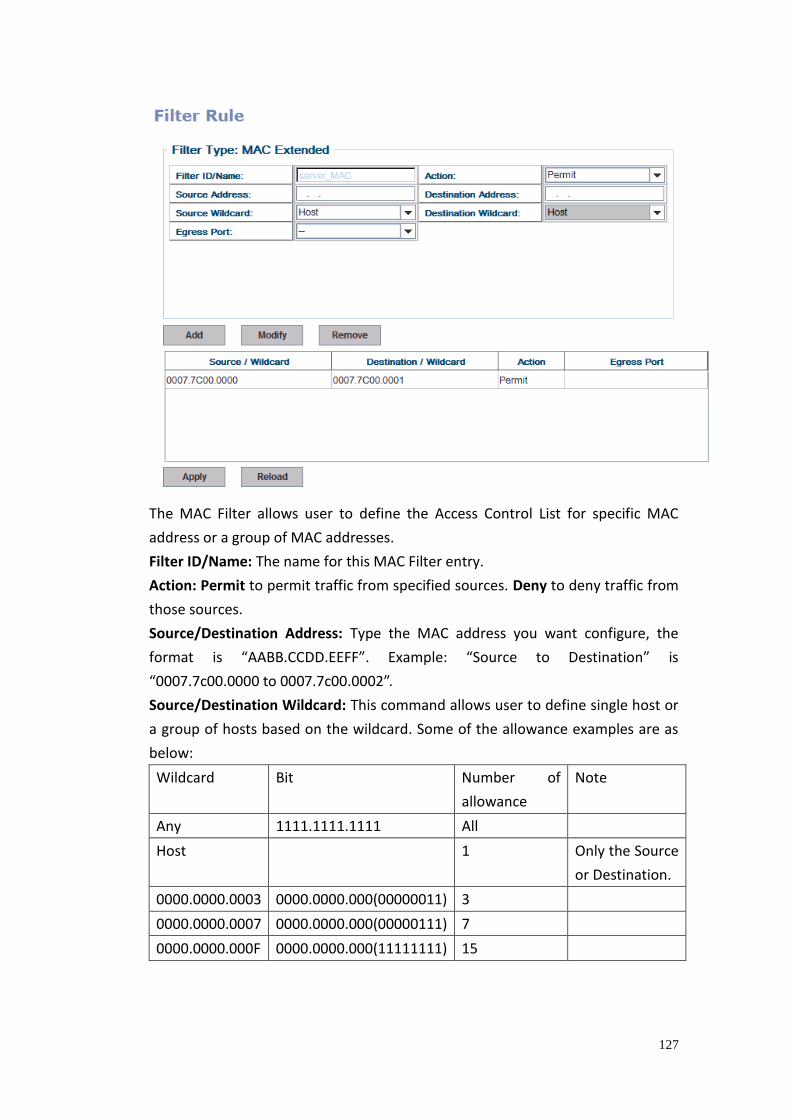
127
The MAC Filter allows user to define the Access Control List for specific MAC
address or a group of MAC addresses.
Filter ID/Name: The name for this MAC Filter entry.
Action: Permit to permit traffic from specified sources. Deny to deny traffic from
those sources.
Source/Destination Address: Type the MAC address you want configure, the
format is “AABB.CCDD.EEFF”. Example: “Source to Destination” is
“0007.7c00.0000 to 0007.7c00.0002”.
Source/Destination Wildcard: This command allows user to define single host or
a group of hosts based on the wildcard. Some of the allowance examples are as
below:
Wildcard Bit Number of
allowance
Note
Any 1111.1111.1111 All
Host 1 Only the Source
or Destination.
0000.0000.0003 0000.0000.000(00000011) 3
0000.0000.0007 0000.0000.000(00000111) 7
0000.0000.000F 0000.0000.000(11111111) 15
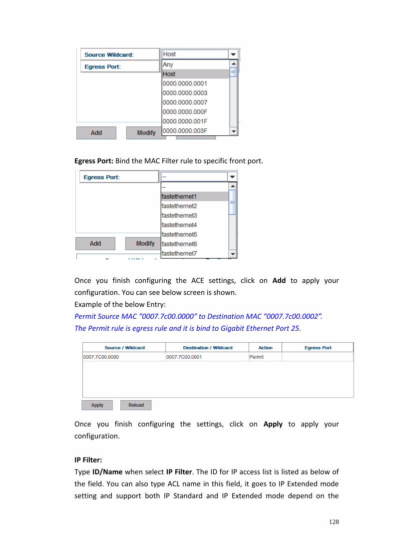
128
Egress Port: Bind the MAC Filter rule to specific front port.
Once you finish configuring the ACE settings, click on Add to apply your
configuration. You can see below screen is shown.
Example of the below Entry:
Permit Source MAC “0007.7c00.0000” to Destination MAC “0007.7c00.0002”.
The Permit rule is egress rule and it is bind to Gigabit Ethernet Port 25.
Once you finish configuring the settings, click on Apply to apply your
configuration.
IP Filter:
Type ID/Name when select IP Filter. The ID for IP access list is listed as below of
the field. You can also type ACL name in this field, it goes to IP Extended mode
setting and support both IP Standard and IP Extended mode depend on the
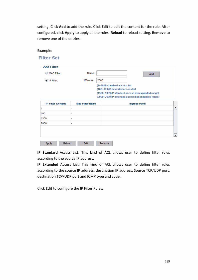
129
setting. Click Add to add the rule. Click Edit to edit the content for the rule. After
configured, click Apply to apply all the rules. Reload to reload setting. Remove to
remove one of the entries.
Example:
IP Standard Access List: This kind of ACL allows user to define filter rules
according to the source IP address.
IP Extended Access List: This kind of ACL allows user to define filter rules
according to the source IP address, destination IP address, Source TCP/UDP port,
destination TCP/UDP port and ICMP type and code.
Click Edit to configure the IP Filter Rules.
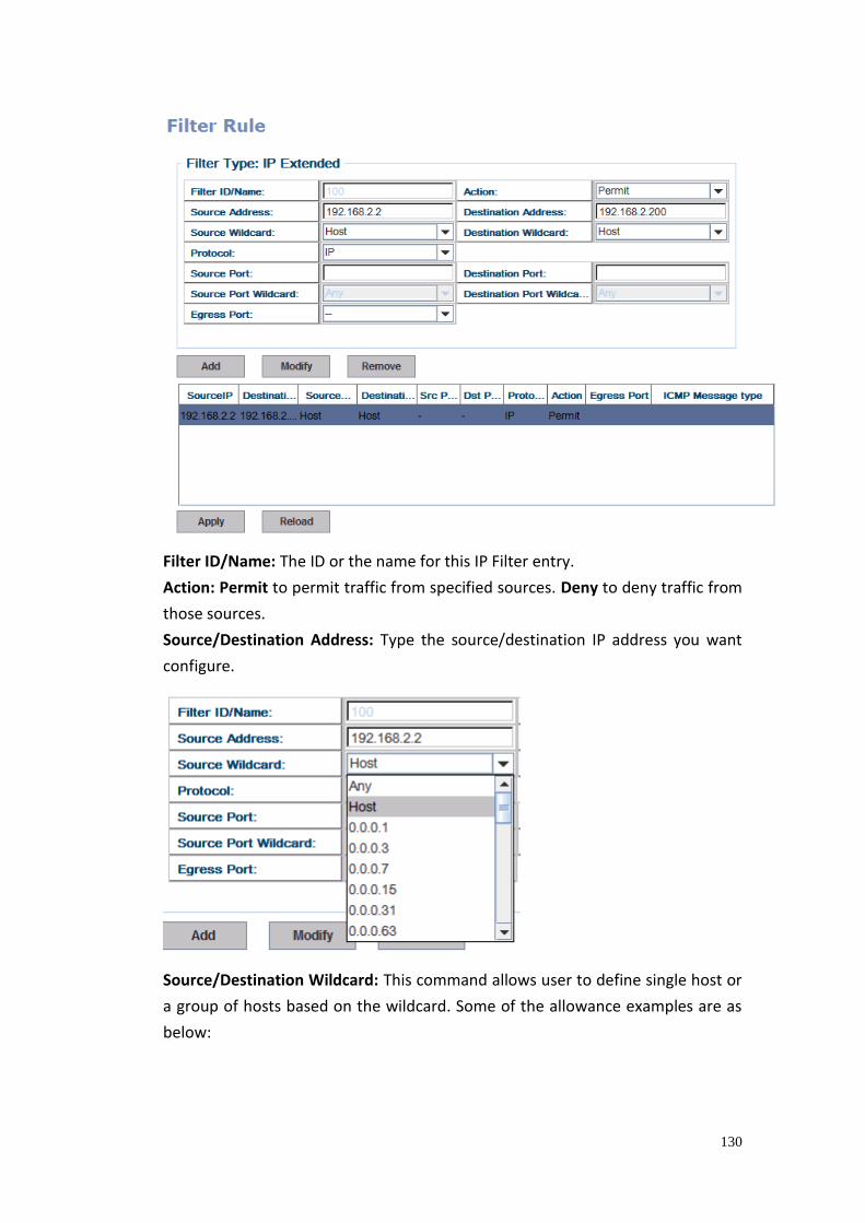
130
Filter ID/Name: The ID or the name for this IP Filter entry.
Action: Permit to permit traffic from specified sources. Deny to deny traffic from
those sources.
Source/Destination Address: Type the source/destination IP address you want
configure.
Source/Destination Wildcard: This command allows user to define single host or
a group of hosts based on the wildcard. Some of the allowance examples are as
below:
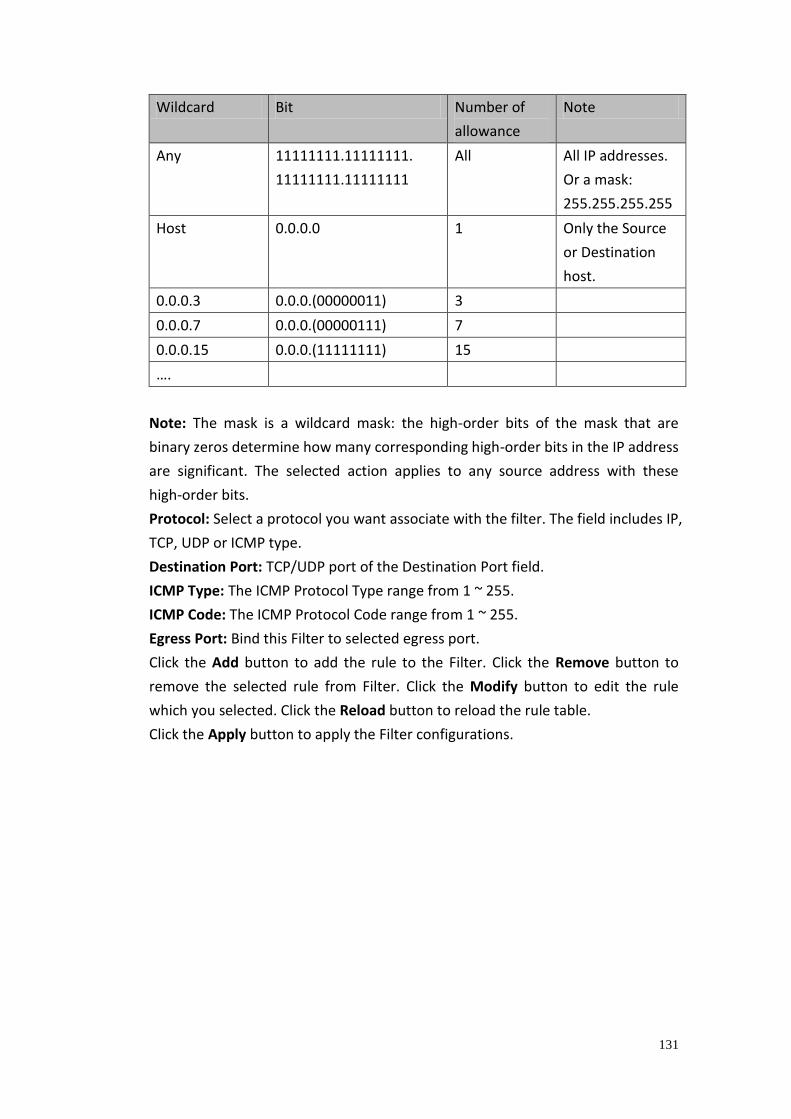
131
Wildcard Bit Number of
allowance
Note
Any 11111111.11111111.
11111111.11111111
All All IP addresses.
Or a mask:
255.255.255.255
Host 0.0.0.0 1 Only the Source
or Destination
host.
0.0.0.3 0.0.0.(00000011) 3
0.0.0.7 0.0.0.(00000111) 7
0.0.0.15 0.0.0.(11111111) 15
….
Note: The mask is a wildcard mask: the high-order bits of the mask that are
binary zeros determine how many corresponding high-order bits in the IP address
are significant. The selected action applies to any source address with these
high-order bits.
Protocol: Select a protocol you want associate with the filter. The field includes IP,
TCP, UDP or ICMP type.
Destination Port: TCP/UDP port of the Destination Port field.
ICMP Type: The ICMP Protocol Type range from 1 ~ 255.
ICMP Code: The ICMP Protocol Code range from 1 ~ 255.
Egress Port: Bind this Filter to selected egress port.
Click the Add button to add the rule to the Filter. Click the Remove button to
remove the selected rule from Filter. Click the Modify button to edit the rule
which you selected. Click the Reload button to reload the rule table.
Click the Apply button to apply the Filter configurations.
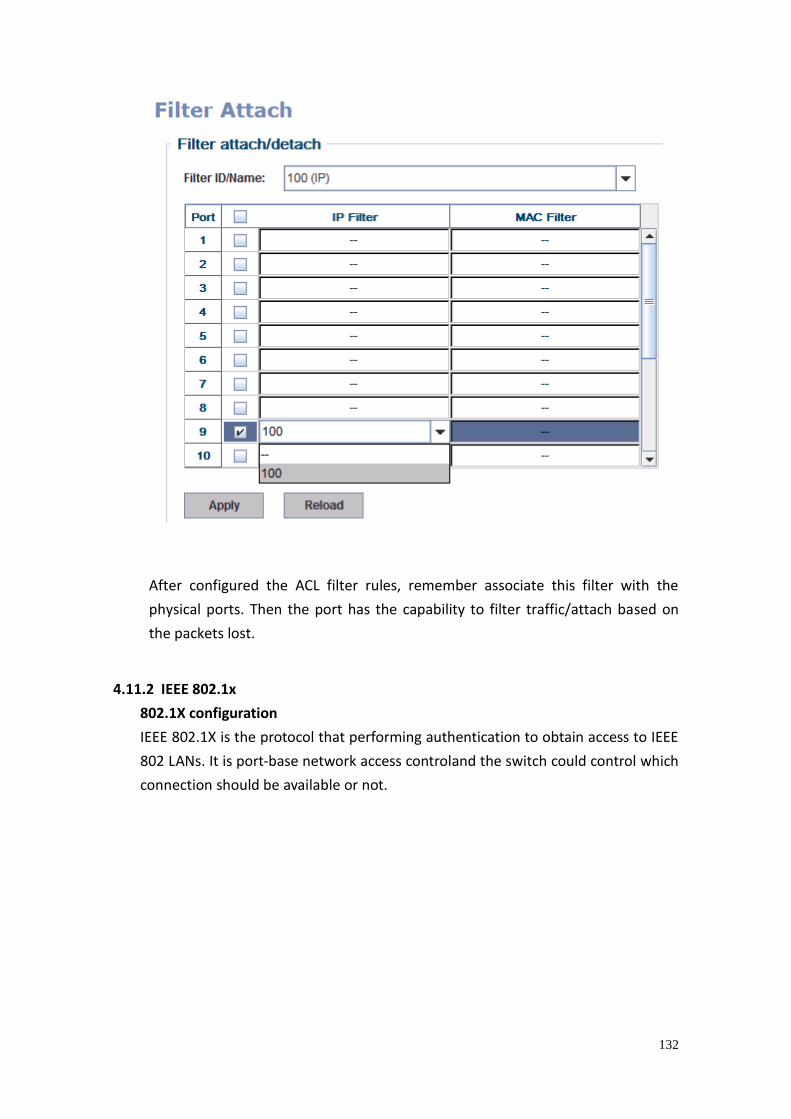
132
After configured the ACL filter rules, remember associate this filter with the
physical ports. Then the port has the capability to filter traffic/attach based on
the packets lost.
4.11.2 IEEE 802.1x
802.1X configuration
IEEE 802.1X is the protocol that performing authentication to obtain access to IEEE
802 LANs. It is port-base network access controland the switch could control which
connection should be available or not.
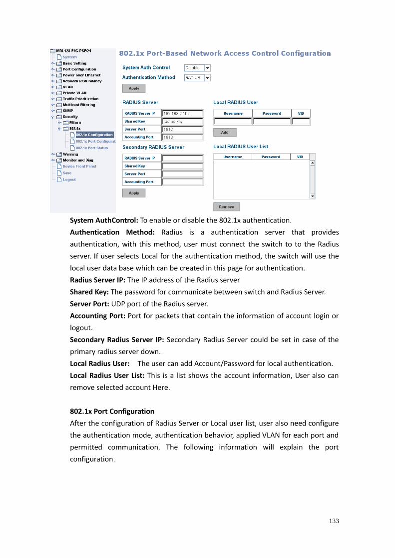
133
System AuthControl: To enable or disable the 802.1x authentication.
Authentication Method: Radius is a authentication server that provides
authentication, with this method, user must connect the switch to to the Radius
server. If user selects Local for the authentication method, the switch will use the
local user data base which can be created in this page for authentication.
Radius Server IP: The IP address of the Radius server
Shared Key: The password for communicate between switch and Radius Server.
Server Port: UDP port of the Radius server.
Accounting Port: Port for packets that contain the information of account login or
logout.
Secondary Radius Server IP: Secondary Radius Server could be set in case of the
primary radius server down.
Local Radius User: The user can add Account/Password for local authentication.
Local Radius User List: This is a list shows the account information, User also can
remove selected account Here.
802.1x Port Configuration
After the configuration of Radius Server or Local user list, user also need configure
the authentication mode, authentication behavior, applied VLAN for each port and
permitted communication. The following information will explain the port
configuration.
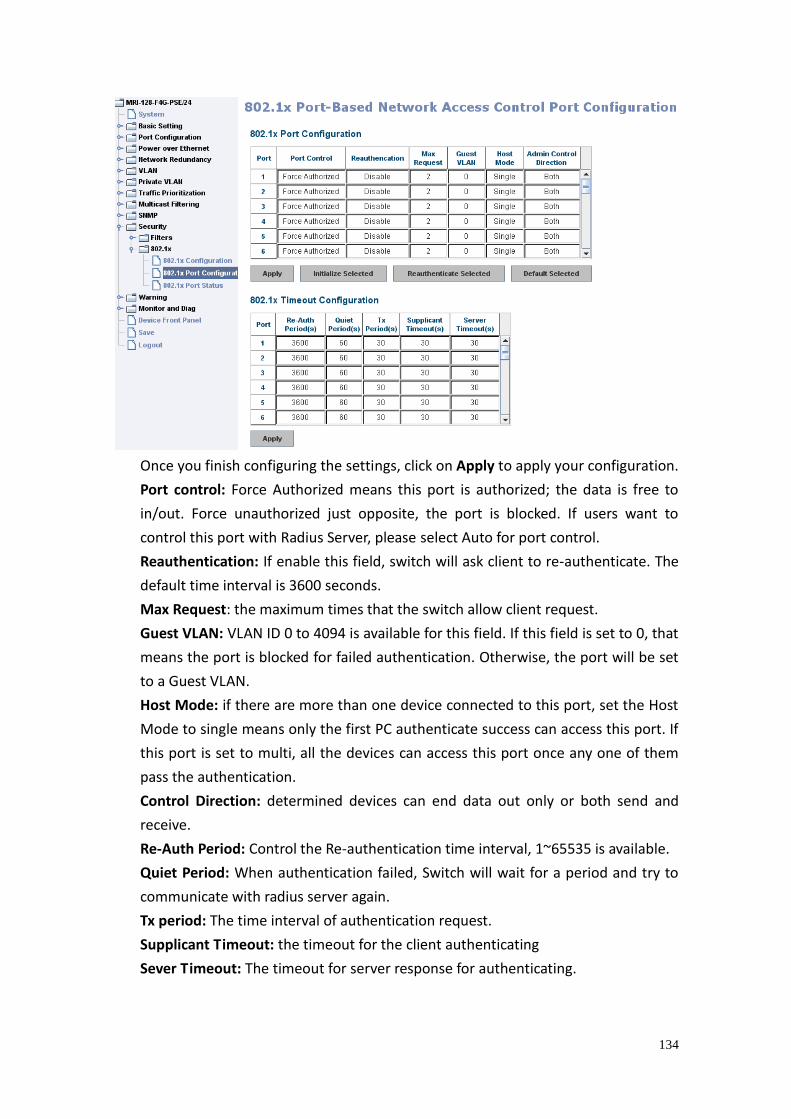
134
Once you finish configuring the settings, click on Apply to apply your configuration.
Port control: Force Authorized means this port is authorized; the data is free to
in/out. Force unauthorized just opposite, the port is blocked. If users want to
control this port with Radius Server, please select Auto for port control.
Reauthentication: If enable this field, switch will ask client to re-authenticate. The
default time interval is 3600 seconds.
Max Request: the maximum times that the switch allow client request.
Guest VLAN: VLAN ID 0 to 4094 is available for this field. If this field is set to 0, that
means the port is blocked for failed authentication. Otherwise, the port will be set
to a Guest VLAN.
Host Mode: if there are more than one device connected to this port, set the Host
Mode to single means only the first PC authenticate success can access this port. If
this port is set to multi, all the devices can access this port once any one of them
pass the authentication.
Control Direction: determined devices can end data out only or both send and
receive.
Re-Auth Period: Control the Re-authentication time interval, 1~65535 is available.
Quiet Period: When authentication failed, Switch will wait for a period and try to
communicate with radius server again.
Tx period: The time interval of authentication request.
Supplicant Timeout: the timeout for the client authenticating
Sever Timeout: The timeout for server response for authenticating.
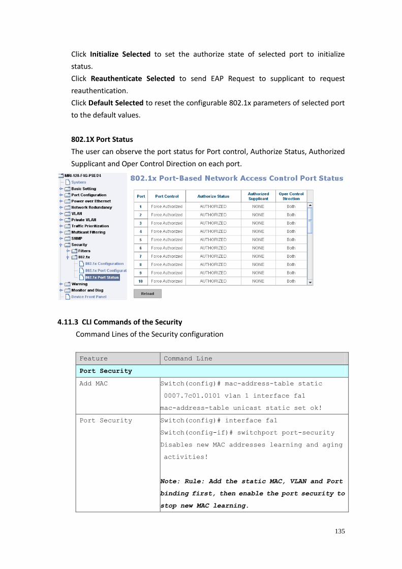
135
Click Initialize Selected to set the authorize state of selected port to initialize
status.
Click Reauthenticate Selected to send EAP Request to supplicant to request
reauthentication.
Click Default Selected to reset the configurable 802.1x parameters of selected port
to the default values.
802.1X Port Status
The user can observe the port status for Port control, Authorize Status, Authorized
Supplicant and Oper Control Direction on each port.
4.11.3 CLI Commands of the Security
Command Lines of the Security configuration
Feature Command Line
Port Security
Add MAC Switch(config)# mac-address-table static
0007.7c01.0101 vlan 1 interface fa1
mac-address-table unicast static set ok!
Port Security Switch(config)# interface fa1
Switch(config-if)# switchport port-security
Disables new MAC addresses learning and aging
activities!
Note: Rule: Add the static MAC, VLAN and Port
binding first, then enable the port security to
stop new MAC learning.
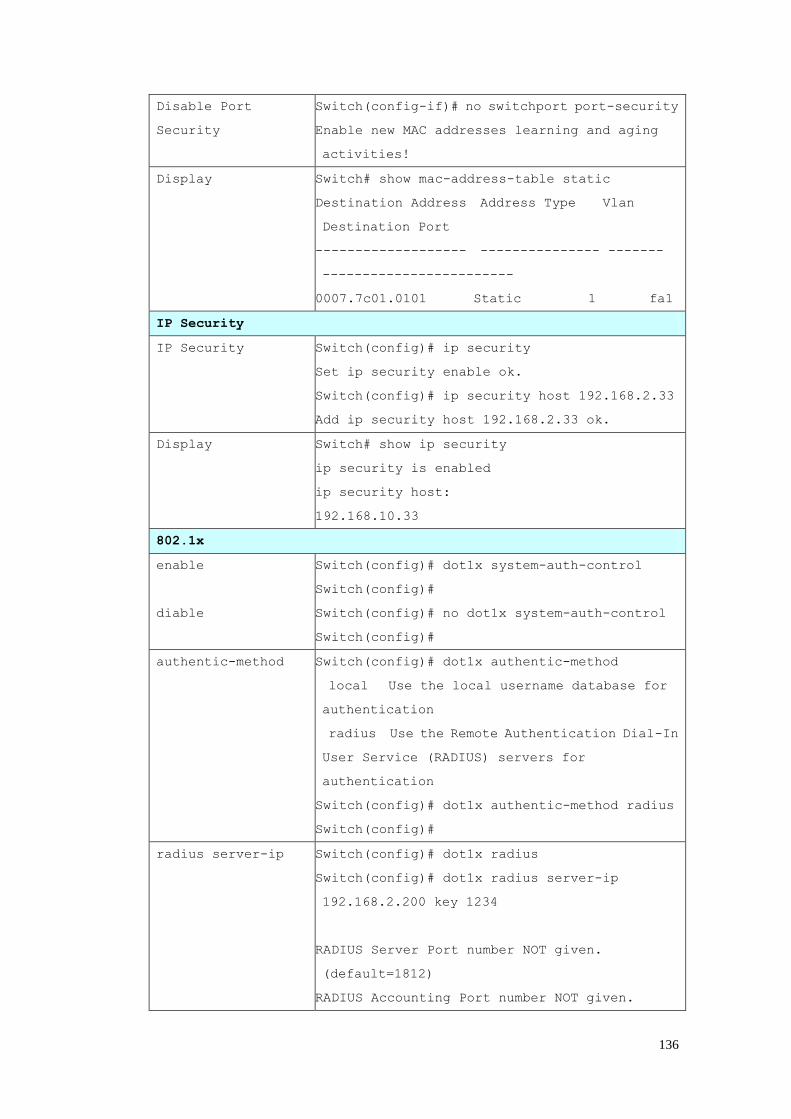
136
Disable Port
Security
Switch(config-if)# no switchport port-security
Enable new MAC addresses learning and aging
activities!
Display Switch# show mac-address-table static
Destination Address Address Type Vlan
Destination Port
------------------- --------------- -------
------------------------
0007.7c01.0101 Static 1 fa1
IP Security
IP Security Switch(config)# ip security
Set ip security enable ok.
Switch(config)# ip security host 192.168.2.33
Add ip security host 192.168.2.33 ok.
Display Switch# show ip security
ip security is enabled
ip security host:
192.168.10.33
802.1x
enable
diable
Switch(config)# dot1x system-auth-control
Switch(config)#
Switch(config)# no dot1x system-auth-control
Switch(config)#
authentic-method Switch(config)# dot1x authentic-method
local Use the local username database for
authentication
radius Use the Remote Authentication Dial-In
User Service (RADIUS) servers for
authentication
Switch(config)# dot1x authentic-method radius
Switch(config)#
radius server-ip Switch(config)# dot1x radius
Switch(config)# dot1x radius server-ip
192.168.2.200 key 1234
RADIUS Server Port number NOT given.
(default=1812)
RADIUS Accounting Port number NOT given.
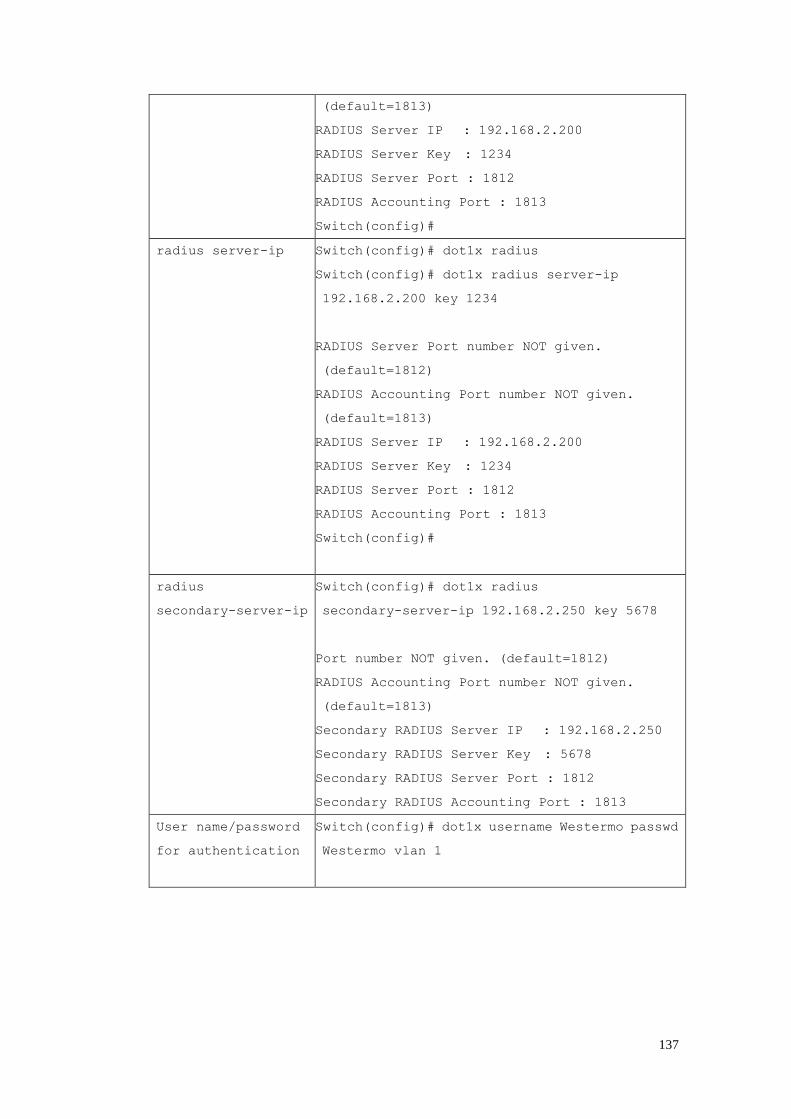
137
(default=1813)
RADIUS Server IP : 192.168.2.200
RADIUS Server Key : 1234
RADIUS Server Port : 1812
RADIUS Accounting Port : 1813
Switch(config)#
radius server-ip Switch(config)# dot1x radius
Switch(config)# dot1x radius server-ip
192.168.2.200 key 1234
RADIUS Server Port number NOT given.
(default=1812)
RADIUS Accounting Port number NOT given.
(default=1813)
RADIUS Server IP : 192.168.2.200
RADIUS Server Key : 1234
RADIUS Server Port : 1812
RADIUS Accounting Port : 1813
Switch(config)#
radius
secondary-server-ip
Switch(config)# dot1x radius
secondary-server-ip 192.168.2.250 key 5678
Port number NOT given. (default=1812)
RADIUS Accounting Port number NOT given.
(default=1813)
Secondary RADIUS Server IP : 192.168.2.250
Secondary RADIUS Server Key : 5678
Secondary RADIUS Server Port : 1812
Secondary RADIUS Accounting Port : 1813
User name/password
for authentication
Switch(config)# dot1x username Westermo passwd
Westermo vlan 1
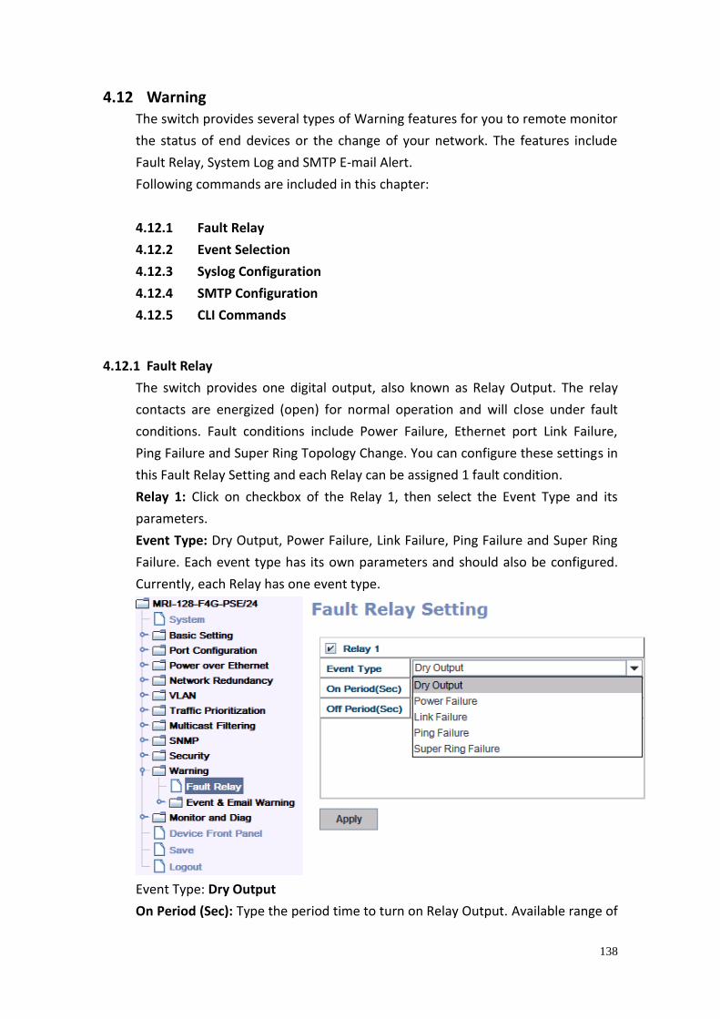
138
4.12 Warning The switch provides several types of Warning features for you to remote monitor
the status of end devices or the change of your network. The features include
Fault Relay, System Log and SMTP E-mail Alert.
Following commands are included in this chapter:
4.12.1 Fault Relay
4.12.2 Event Selection
4.12.3 Syslog Configuration
4.12.4 SMTP Configuration
4.12.5 CLI Commands
4.12.1 Fault Relay
The switch provides one digital output, also known as Relay Output. The relay
contacts are energized (open) for normal operation and will close under fault
conditions. Fault conditions include Power Failure, Ethernet port Link Failure,
Ping Failure and Super Ring Topology Change. You can configure these settings in
this Fault Relay Setting and each Relay can be assigned 1 fault condition.
Relay 1: Click on checkbox of the Relay 1, then select the Event Type and its
parameters.
Event Type: Dry Output, Power Failure, Link Failure, Ping Failure and Super Ring
Failure. Each event type has its own parameters and should also be configured.
Currently, each Relay has one event type.
Event Type: Dry Output
On Period (Sec): Type the period time to turn on Relay Output. Available range of
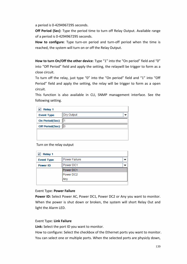
139
a period is 0-4294967295 seconds.
Off Period (Sec): Type the period time to turn off Relay Output. Available range
of a period is 0-4294967295 seconds.
How to configure: Type turn-on period and turn-off period when the time is
reached, the system will turn on or off the Relay Output.
How to turn On/Off the other device: Type “1” into the “On period” field and “0”
into “Off Period” field and apply the setting, the relaywill be trigger to form as a
close circuit.
To turn off the relay, just type “0” into the “On period” field and “1” into “Off
Period” field and apply the setting, the relay will be trigger to form as a open
circuit.
This function is also available in CLI, SNMP management interface. See the
following setting.
Event Type: Power Failure
Power ID: Select Power AC, Power DC1, Power DC2 or Any you want to monitor.
When the power is shut down or broken, the system will short Relay Out and
light the Alarm LED.
Event Type: Link Failure
Link: Select the port ID you want to monitor.
How to configure: Select the checkbox of the Ethernet ports you want to monitor.
You can select one or multiple ports. When the selected ports are physicly down,
Turn on the relay output
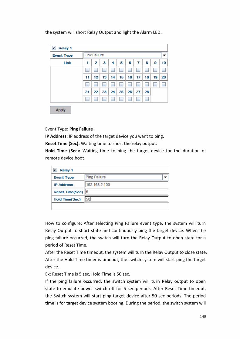
140
the system will short Relay Output and light the Alarm LED.
Event Type: Ping Failure
IP Address: IP address of the target device you want to ping.
Reset Time (Sec): Waiting time to short the relay output.
Hold Time (Sec): Waiting time to ping the target device for the duration of
remote device boot
How to configure: After selecting Ping Failure event type, the system will turn
Relay Output to short state and continuously ping the target device. When the
ping failure occurred, the switch will turn the Relay Output to open state for a
period of Reset Time.
After the Reset Time timeout, the system will turn the Relay Output to close state.
After the Hold Time timer is timeout, the switch system will start ping the target
device.
Ex: Reset Time is 5 sec, Hold Time is 50 sec.
If the ping failure occurred, the switch system will turn Relay output to open
state to emulate power switch off for 5 sec periods. After Reset Time timeout,
the Switch system will start ping target device after 50 sec periods. The period
time is for target device system booting. During the period, the switch system will
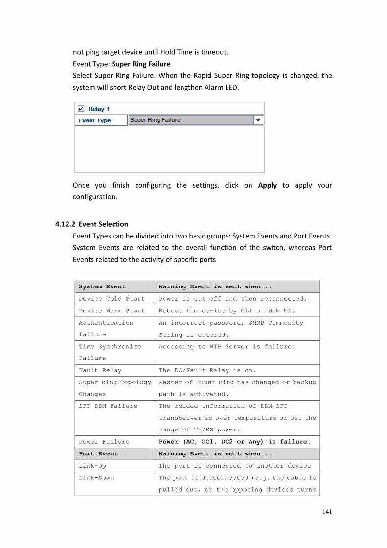
141
not ping target device until Hold Time is timeout.
Event Type: Super Ring Failure
Select Super Ring Failure. When the Rapid Super Ring topology is changed, the
system will short Relay Out and lengthen Alarm LED.
Once you finish configuring the settings, click on Apply to apply your
configuration.
4.12.2 Event Selection
Event Types can be divided into two basic groups: System Events and Port Events.
System Events are related to the overall function of the switch, whereas Port
Events related to the activity of specific ports
System Event Warning Event is sent when…..
Device Cold Start Power is cut off and then reconnected.
Device Warm Start Reboot the device by CLI or Web UI.
Authentication
failure
An incorrect password, SNMP Community
String is entered.
Time Synchronize
Failure
Accessing to NTP Server is failure.
Fault Relay The DO/Fault Relay is on.
Super Ring Topology
Changes
Master of Super Ring has changed or backup
path is activated.
SFP DDM Failure The readed information of DDM SFP
transceiver is over temperature or out the
range of TX/RX power.
Power Failure Power (AC, DC1, DC2 or Any) is failure.
Port Event Warning Event is sent when…..
Link-Up The port is connected to another device
Link-Down The port is disconnected (e.g. the cable is
pulled out, or the opposing devices turns
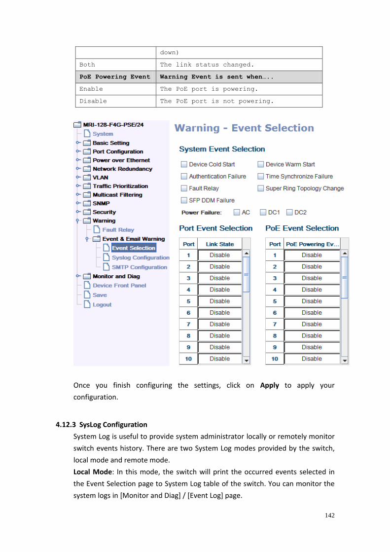
142
down)
Both The link status changed.
PoE Powering Event Warning Event is sent when…..
Enable The PoE port is powering.
Disable The PoE port is not powering.
Once you finish configuring the settings, click on Apply to apply your
configuration.
4.12.3 SysLog Configuration
System Log is useful to provide system administrator locally or remotely monitor
switch events history. There are two System Log modes provided by the switch,
local mode and remote mode.
Local Mode: In this mode, the switch will print the occurred events selected in
the Event Selection page to System Log table of the switch. You can monitor the
system logs in [Monitor and Diag] / [Event Log] page.
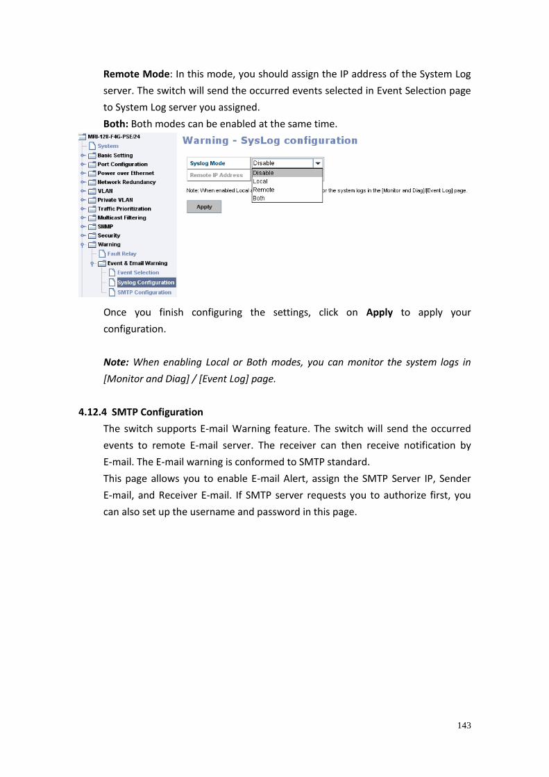
143
Remote Mode: In this mode, you should assign the IP address of the System Log
server. The switch will send the occurred events selected in Event Selection page
to System Log server you assigned.
Both: Both modes can be enabled at the same time.
Once you finish configuring the settings, click on Apply to apply your
configuration.
Note: When enabling Local or Both modes, you can monitor the system logs in
[Monitor and Diag] / [Event Log] page.
4.12.4 SMTP Configuration
The switch supports E-mail Warning feature. The switch will send the occurred
events to remote E-mail server. The receiver can then receive notification by
E-mail. The E-mail warning is conformed to SMTP standard.
This page allows you to enable E-mail Alert, assign the SMTP Server IP, Sender
E-mail, and Receiver E-mail. If SMTP server requests you to authorize first, you
can also set up the username and password in this page.
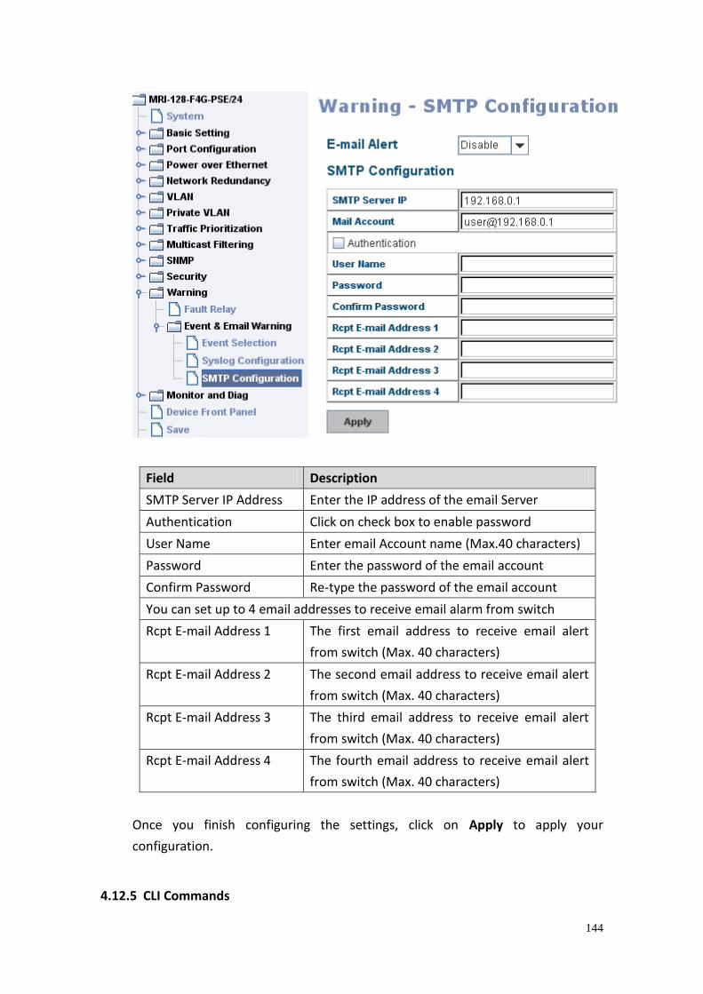
144
Field Description
SMTP Server IP Address Enter the IP address of the email Server
Authentication Click on check box to enable password
User Name Enter email Account name (Max.40 characters)
Password Enter the password of the email account
Confirm Password Re-type the password of the email account
You can set up to 4 email addresses to receive email alarm from switch
Rcpt E-mail Address 1 The first email address to receive email alert
from switch (Max. 40 characters)
Rcpt E-mail Address 2 The second email address to receive email alert
from switch (Max. 40 characters)
Rcpt E-mail Address 3 The third email address to receive email alert
from switch (Max. 40 characters)
Rcpt E-mail Address 4 The fourth email address to receive email alert
from switch (Max. 40 characters)
Once you finish configuring the settings, click on Apply to apply your
configuration.
4.12.5 CLI Commands
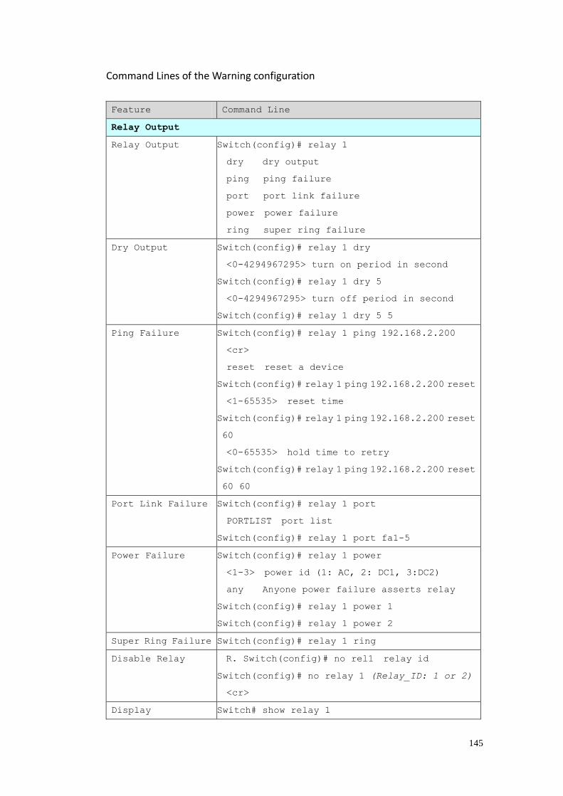
145
Command Lines of the Warning configuration
Feature Command Line
Relay Output
Relay Output Switch(config)# relay 1
dry dry output
ping ping failure
port port link failure
power power failure
ring super ring failure
Dry Output Switch(config)# relay 1 dry
<0-4294967295> turn on period in second
Switch(config)# relay 1 dry 5
<0-4294967295> turn off period in second
Switch(config)# relay 1 dry 5 5
Ping Failure Switch(config)# relay 1 ping 192.168.2.200
<cr>
reset reset a device
Switch(config)# relay 1 ping 192.168.2.200 reset
<1-65535> reset time
Switch(config)# relay 1 ping 192.168.2.200 reset
60
<0-65535> hold time to retry
Switch(config)# relay 1 ping 192.168.2.200 reset
60 60
Port Link Failure Switch(config)# relay 1 port
PORTLIST port list
Switch(config)# relay 1 port fa1-5
Power Failure Switch(config)# relay 1 power
<1-3> power id (1: AC, 2: DC1, 3:DC2)
any Anyone power failure asserts relay
Switch(config)# relay 1 power 1
Switch(config)# relay 1 power 2
Super Ring Failure Switch(config)# relay 1 ring
Disable Relay R. Switch(config)# no rel1 relay id
Switch(config)# no relay 1 (Relay_ID: 1 or 2)
<cr>
Display Switch# show relay 1
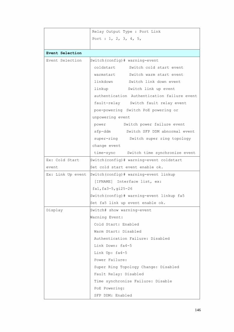
146
Relay Output Type : Port Link
Port : 1, 2, 3, 4, 5,
Event Selection
Event Selection Switch(config)# warning-event
coldstart Switch cold start event
warmstart Switch warm start event
linkdown Switch link down event
linkup Switch link up event
authentication Authentication failure event
fault-relay Switch fault relay event
poe-powering Switch PoE powering or
unpowering event
power Switch power failure event
sfp-ddm Switch SFP DDM abnormal event
super-ring Switch super ring topology
change event
time-sync Switch time synchronize event
Ex: Cold Start
event
Switch(config)# warning-event coldstart
Set cold start event enable ok.
Ex: Link Up event Switch(config)# warning-event linkup
[IFNAME] Interface list, ex:
fa1,fa3-5,gi25-26
Switch(config)# warning-event linkup fa5
Set fa5 link up event enable ok.
Display Switch# show warning-event
Warning Event:
Cold Start: Enabled
Warm Start: Disabled
Authentication Failure: Disabled
Link Down: fa4-5
Link Up: fa4-5
Power Failure:
Super Ring Topology Change: Disabled
Fault Relay: Disabled
Time synchronize Failure: Disable
PoE Powering:
SFP DDM: Enabled
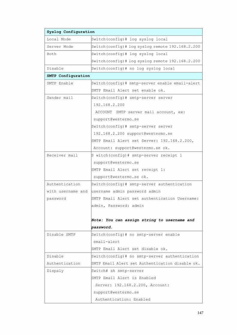
147
Syslog Configuration
Local Mode Switch(config)# log syslog local
Server Mode Switch(config)# log syslog remote 192.168.2.200
Both Switch(config)# log syslog local
Switch(config)# log syslog remote 192.168.2.200
Disable Switch(config)# no log syslog local
SMTP Configuration
SMTP Enable Switch(config)# smtp-server enable email-alert
SMTP Email Alert set enable ok.
Sender mail Switch(config)# smtp-server server
192.168.2.200
ACCOUNT SMTP server mail account, ex:
Switch(config)# smtp-server server
192.168.2.200 [email protected]
SMTP Email Alert set Server: 192.168.2.200,
Account: [email protected] ok.
Receiver mail S witch(config)# smtp-server receipt 1
SMTP Email Alert set receipt 1:
Authentication
with username and
password
Switch(config)# smtp-server authentication
username admin password admin
SMTP Email Alert set authentication Username:
admin, Password: admin
Note: You can assign string to username and
password.
Disable SMTP Switch(config)# no smtp-server enable
email-alert
SMTP Email Alert set disable ok.
Disable
Authentication
Switch(config)# no smtp-server authentication
SMTP Email Alert set Authentication disable ok.
Dispaly Switch# sh smtp-server
SMTP Email Alert is Enabled
Server: 192.168.2.200, Account:
Authentication: Enabled

148
Username: admin, Password: admin
SMTP Email Alert Receipt:
Receipt 1: [email protected]
Receipt 2:
Receipt 3:
Receipt 4:
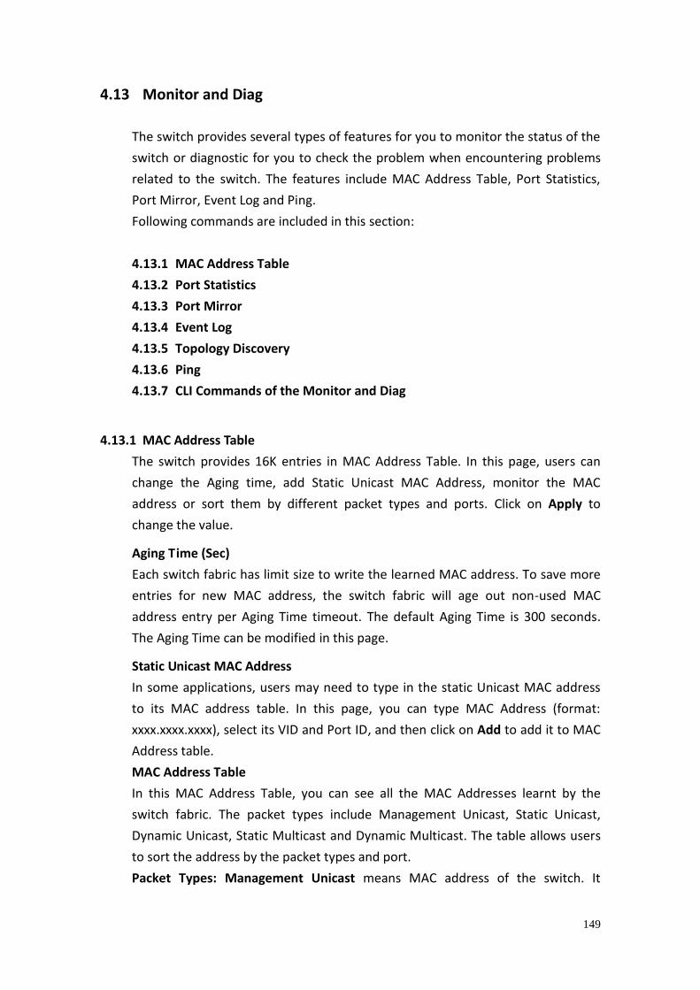
149
4.13 Monitor and Diag
The switch provides several types of features for you to monitor the status of the
switch or diagnostic for you to check the problem when encountering problems
related to the switch. The features include MAC Address Table, Port Statistics,
Port Mirror, Event Log and Ping.
Following commands are included in this section:
4.13.1 MAC Address Table
4.13.2 Port Statistics
4.13.3 Port Mirror
4.13.4 Event Log
4.13.5 Topology Discovery
4.13.6 Ping
4.13.7 CLI Commands of the Monitor and Diag
4.13.1 MAC Address Table
The switch provides 16K entries in MAC Address Table. In this page, users can
change the Aging time, add Static Unicast MAC Address, monitor the MAC
address or sort them by different packet types and ports. Click on Apply to
change the value.
Aging Time (Sec)
Each switch fabric has limit size to write the learned MAC address. To save more
entries for new MAC address, the switch fabric will age out non-used MAC
address entry per Aging Time timeout. The default Aging Time is 300 seconds.
The Aging Time can be modified in this page.
Static Unicast MAC Address
In some applications, users may need to type in the static Unicast MAC address
to its MAC address table. In this page, you can type MAC Address (format:
xxxx.xxxx.xxxx), select its VID and Port ID, and then click on Add to add it to MAC
Address table.
MAC Address Table
In this MAC Address Table, you can see all the MAC Addresses learnt by the
switch fabric. The packet types include Management Unicast, Static Unicast,
Dynamic Unicast, Static Multicast and Dynamic Multicast. The table allows users
to sort the address by the packet types and port.
Packet Types: Management Unicast means MAC address of the switch. It
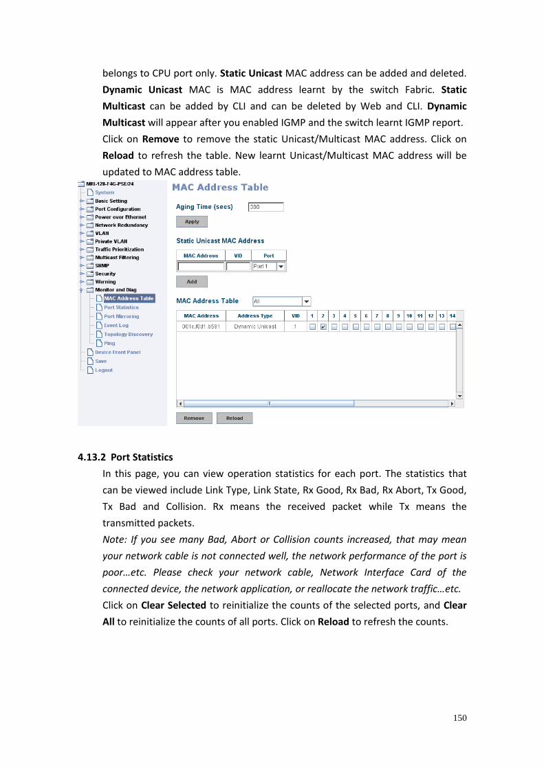
150
belongs to CPU port only. Static Unicast MAC address can be added and deleted.
Dynamic Unicast MAC is MAC address learnt by the switch Fabric. Static
Multicast can be added by CLI and can be deleted by Web and CLI. Dynamic
Multicast will appear after you enabled IGMP and the switch learnt IGMP report.
Click on Remove to remove the static Unicast/Multicast MAC address. Click on
Reload to refresh the table. New learnt Unicast/Multicast MAC address will be
updated to MAC address table.
4.13.2 Port Statistics
In this page, you can view operation statistics for each port. The statistics that
can be viewed include Link Type, Link State, Rx Good, Rx Bad, Rx Abort, Tx Good,
Tx Bad and Collision. Rx means the received packet while Tx means the
transmitted packets.
Note: If you see many Bad, Abort or Collision counts increased, that may mean
your network cable is not connected well, the network performance of the port is
poor…etc. Please check your network cable, Network Interface Card of the
connected device, the network application, or reallocate the network traffic…etc.
Click on Clear Selected to reinitialize the counts of the selected ports, and Clear
All to reinitialize the counts of all ports. Click on Reload to refresh the counts.
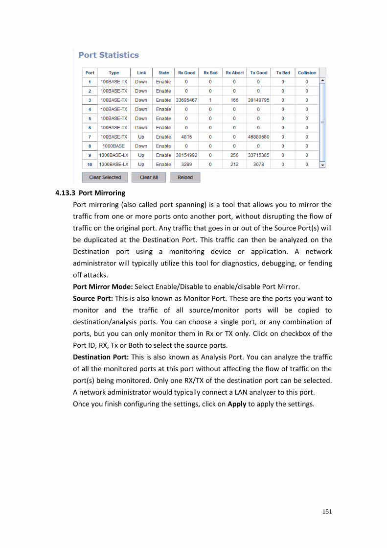
151
4.13.3 Port Mirroring
Port mirroring (also called port spanning) is a tool that allows you to mirror the
traffic from one or more ports onto another port, without disrupting the flow of
traffic on the original port. Any traffic that goes in or out of the Source Port(s) will
be duplicated at the Destination Port. This traffic can then be analyzed on the
Destination port using a monitoring device or application. A network
administrator will typically utilize this tool for diagnostics, debugging, or fending
off attacks.
Port Mirror Mode: Select Enable/Disable to enable/disable Port Mirror.
Source Port: This is also known as Monitor Port. These are the ports you want to
monitor and the traffic of all source/monitor ports will be copied to
destination/analysis ports. You can choose a single port, or any combination of
ports, but you can only monitor them in Rx or TX only. Click on checkbox of the
Port ID, RX, Tx or Both to select the source ports.
Destination Port: This is also known as Analysis Port. You can analyze the traffic
of all the monitored ports at this port without affecting the flow of traffic on the
port(s) being monitored. Only one RX/TX of the destination port can be selected.
A network administrator would typically connect a LAN analyzer to this port.
Once you finish configuring the settings, click on Apply to apply the settings.
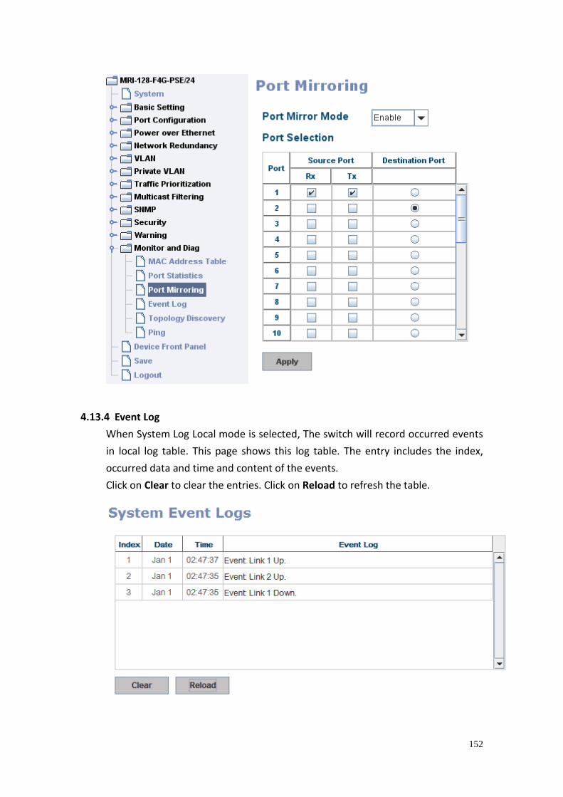
152
4.13.4 Event Log
When System Log Local mode is selected, The switch will record occurred events
in local log table. This page shows this log table. The entry includes the index,
occurred data and time and content of the events.
Click on Clear to clear the entries. Click on Reload to refresh the table.
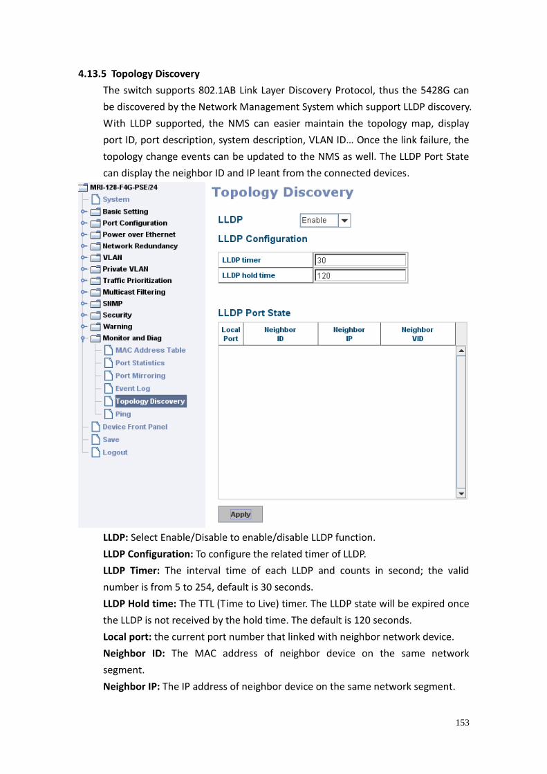
153
4.13.5 Topology Discovery
The switch supports 802.1AB Link Layer Discovery Protocol, thus the 5428G can
be discovered by the Network Management System which support LLDP discovery.
With LLDP supported, the NMS can easier maintain the topology map, display
port ID, port description, system description, VLAN ID… Once the link failure, the
topology change events can be updated to the NMS as well. The LLDP Port State
can display the neighbor ID and IP leant from the connected devices.
LLDP: Select Enable/Disable to enable/disable LLDP function.
LLDP Configuration: To configure the related timer of LLDP.
LLDP Timer: The interval time of each LLDP and counts in second; the valid
number is from 5 to 254, default is 30 seconds.
LLDP Hold time: The TTL (Time to Live) timer. The LLDP state will be expired once
the LLDP is not received by the hold time. The default is 120 seconds.
Local port: the current port number that linked with neighbor network device.
Neighbor ID: The MAC address of neighbor device on the same network
segment.
Neighbor IP: The IP address of neighbor device on the same network segment.
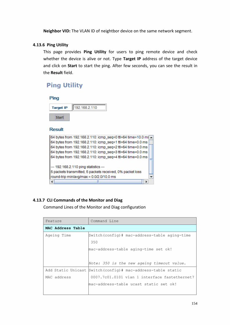
154
Neighbor VID: The VLAN ID of neightbor device on the same network segment.
4.13.6 Ping Utility
This page provides Ping Utility for users to ping remote device and check
whether the device is alive or not. Type Target IP address of the target device
and click on Start to start the ping. After few seconds, you can see the result in
the Result field.
4.13.7 CLI Commands of the Monitor and Diag
Command Lines of the Monitor and Diag configuration
Feature Command Line
MAC Address Table
Ageing Time Switch(config)# mac-address-table aging-time
350
mac-address-table aging-time set ok!
Note: 350 is the new ageing timeout value.
Add Static Unicast
MAC address
Switch(config)# mac-address-table static
0007.7c01.0101 vlan 1 interface fastethernet7
mac-address-table ucast static set ok!
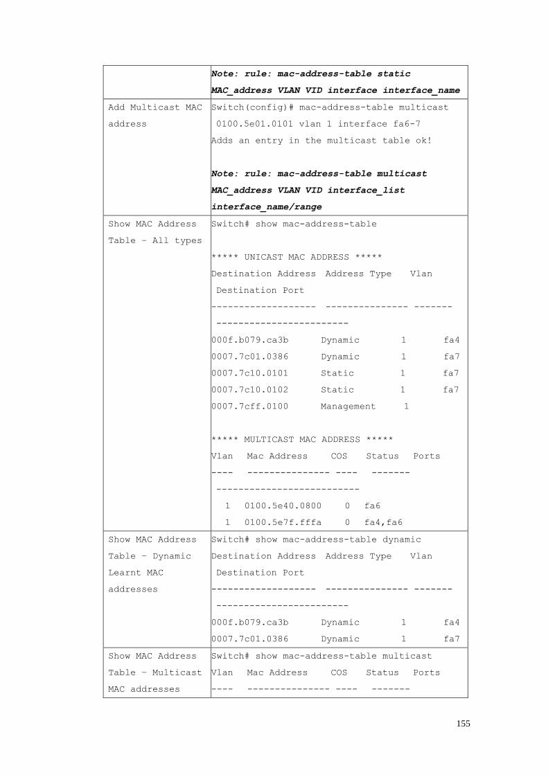
155
Note: rule: mac-address-table static
MAC_address VLAN VID interface interface_name
Add Multicast MAC
address
Switch(config)# mac-address-table multicast
0100.5e01.0101 vlan 1 interface fa6-7
Adds an entry in the multicast table ok!
Note: rule: mac-address-table multicast
MAC_address VLAN VID interface_list
interface_name/range
Show MAC Address
Table – All types
Switch# show mac-address-table
***** UNICAST MAC ADDRESS *****
Destination Address Address Type Vlan
Destination Port
------------------- --------------- -------
------------------------
000f.b079.ca3b Dynamic 1 fa4
0007.7c01.0386 Dynamic 1 fa7
0007.7c10.0101 Static 1 fa7
0007.7c10.0102 Static 1 fa7
0007.7cff.0100 Management 1
***** MULTICAST MAC ADDRESS *****
Vlan Mac Address COS Status Ports
---- --------------- ---- -------
--------------------------
1 0100.5e40.0800 0 fa6
1 0100.5e7f.fffa 0 fa4,fa6
Show MAC Address
Table – Dynamic
Learnt MAC
addresses
Switch# show mac-address-table dynamic
Destination Address Address Type Vlan
Destination Port
------------------- --------------- -------
------------------------
000f.b079.ca3b Dynamic 1 fa4
0007.7c01.0386 Dynamic 1 fa7
Show MAC Address
Table – Multicast
MAC addresses
Switch# show mac-address-table multicast
Vlan Mac Address COS Status Ports
---- --------------- ---- -------
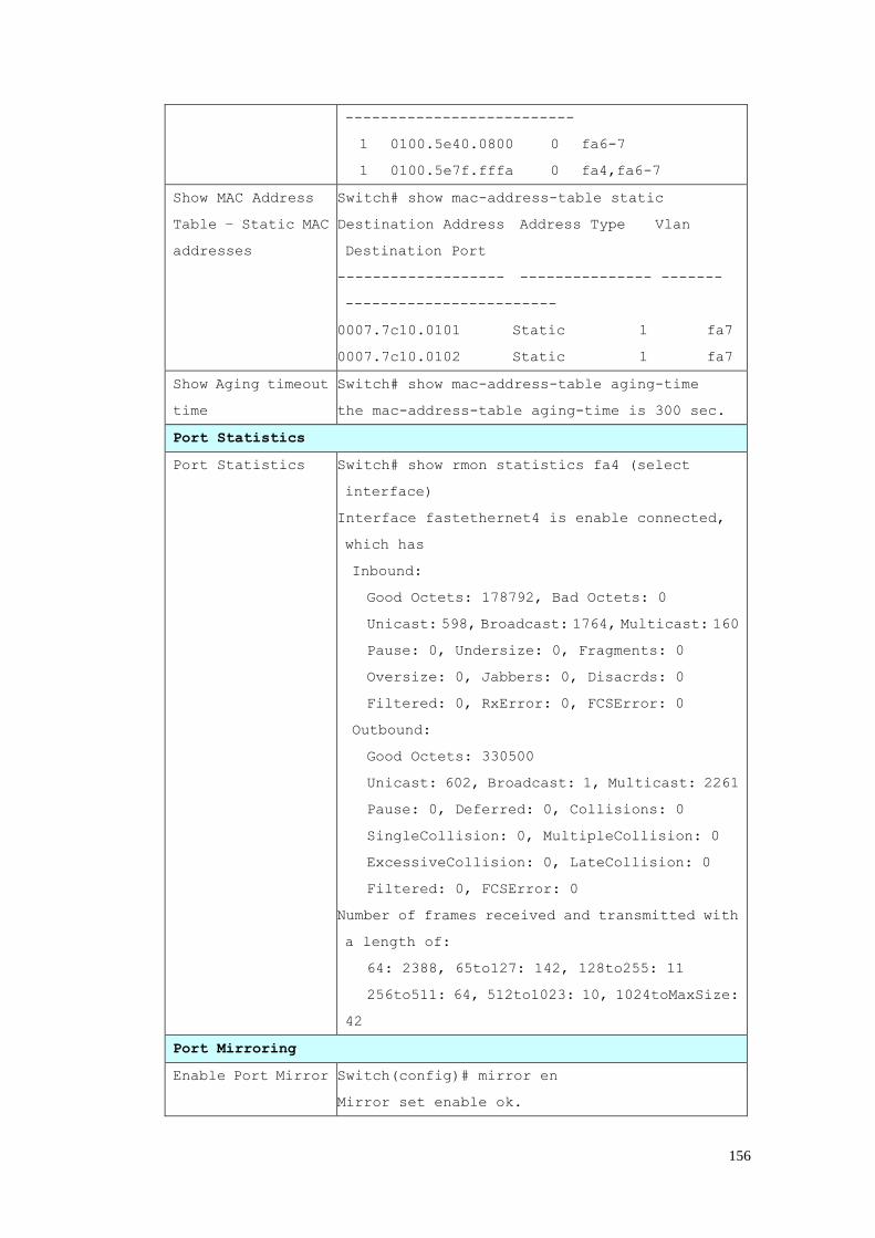
156
--------------------------
1 0100.5e40.0800 0 fa6-7
1 0100.5e7f.fffa 0 fa4,fa6-7
Show MAC Address
Table – Static MAC
addresses
Switch# show mac-address-table static
Destination Address Address Type Vlan
Destination Port
------------------- --------------- -------
------------------------
0007.7c10.0101 Static 1 fa7
0007.7c10.0102 Static 1 fa7
Show Aging timeout
time
Switch# show mac-address-table aging-time
the mac-address-table aging-time is 300 sec.
Port Statistics
Port Statistics Switch# show rmon statistics fa4 (select
interface)
Interface fastethernet4 is enable connected,
which has
Inbound:
Good Octets: 178792, Bad Octets: 0
Unicast: 598, Broadcast: 1764, Multicast: 160
Pause: 0, Undersize: 0, Fragments: 0
Oversize: 0, Jabbers: 0, Disacrds: 0
Filtered: 0, RxError: 0, FCSError: 0
Outbound:
Good Octets: 330500
Unicast: 602, Broadcast: 1, Multicast: 2261
Pause: 0, Deferred: 0, Collisions: 0
SingleCollision: 0, MultipleCollision: 0
ExcessiveCollision: 0, LateCollision: 0
Filtered: 0, FCSError: 0
Number of frames received and transmitted with
a length of:
64: 2388, 65to127: 142, 128to255: 11
256to511: 64, 512to1023: 10, 1024toMaxSize:
42
Port Mirroring
Enable Port Mirror Switch(config)# mirror en
Mirror set enable ok.
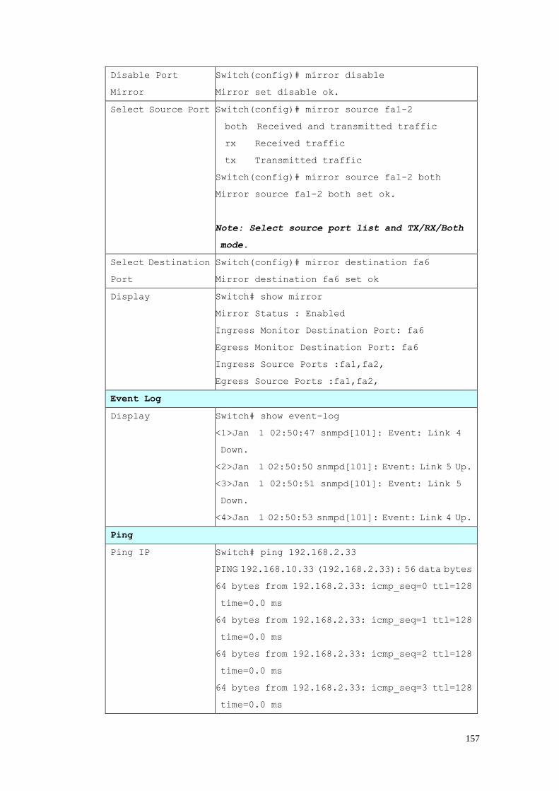
157
Disable Port
Mirror
Switch(config)# mirror disable
Mirror set disable ok.
Select Source Port Switch(config)# mirror source fa1-2
both Received and transmitted traffic
rx Received traffic
tx Transmitted traffic
Switch(config)# mirror source fa1-2 both
Mirror source fa1-2 both set ok.
Note: Select source port list and TX/RX/Both
mode.
Select Destination
Port
Switch(config)# mirror destination fa6
Mirror destination fa6 set ok
Display Switch# show mirror
Mirror Status : Enabled
Ingress Monitor Destination Port: fa6
Egress Monitor Destination Port: fa6
Ingress Source Ports :fa1,fa2,
Egress Source Ports :fa1,fa2,
Event Log
Display Switch# show event-log
<1>Jan 1 02:50:47 snmpd[101]: Event: Link 4
Down.
<2>Jan 1 02:50:50 snmpd[101]: Event: Link 5 Up.
<3>Jan 1 02:50:51 snmpd[101]: Event: Link 5
Down.
<4>Jan 1 02:50:53 snmpd[101]: Event: Link 4 Up.
Ping
Ping IP Switch# ping 192.168.2.33
PING 192.168.10.33 (192.168.2.33): 56 data bytes
64 bytes from 192.168.2.33: icmp_seq=0 ttl=128
time=0.0 ms
64 bytes from 192.168.2.33: icmp_seq=1 ttl=128
time=0.0 ms
64 bytes from 192.168.2.33: icmp_seq=2 ttl=128
time=0.0 ms
64 bytes from 192.168.2.33: icmp_seq=3 ttl=128
time=0.0 ms

158
64 bytes from 192.168.2.33: icmp_seq=4 ttl=128
time=0.0 ms
--- 192.168.2.33 ping statistics ---
5 packets transmitted, 5 packets received, 0%
packet loss
round-trip min/avg/max = 0.0/0.0/0.0 ms
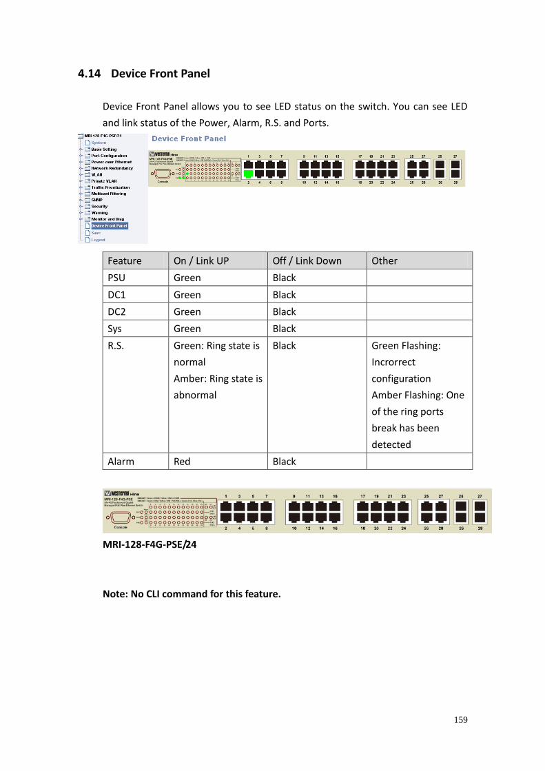
159
4.14 Device Front Panel
Device Front Panel allows you to see LED status on the switch. You can see LED
and link status of the Power, Alarm, R.S. and Ports.
Feature On / Link UP Off / Link Down Other
PSU Green Black
DC1 Green Black
DC2 Green Black
Sys Green Black
R.S. Green: Ring state is
normal
Amber: Ring state is
abnormal
Black Green Flashing:
Incrorrect
configuration
Amber Flashing: One
of the ring ports
break has been
detected
Alarm Red Black
MRI-128-F4G-PSE/24
Note: No CLI command for this feature.
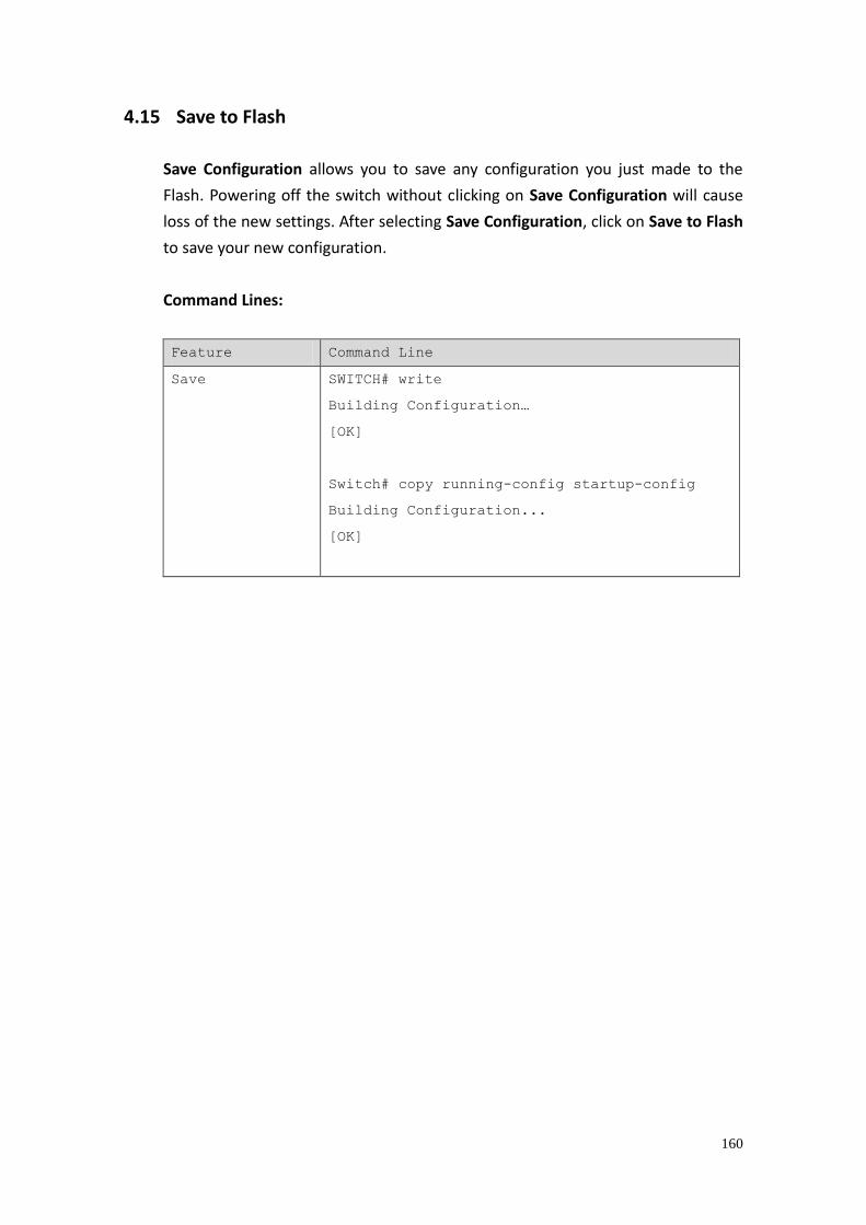
160
4.15 Save to Flash
Save Configuration allows you to save any configuration you just made to the
Flash. Powering off the switch without clicking on Save Configuration will cause
loss of the new settings. After selecting Save Configuration, click on Save to Flash
to save your new configuration.
Command Lines:
Feature Command Line
Save SWITCH# write
Building Configuration…
[OK]
Switch# copy running-config startup-config
Building Configuration...
[OK]

161
4.16 Logout
The switch provides two logout methods. The web connection will be logged out
if you don’t input any command after 30 seconds. The Logout command allows
you to manually logout the web connection. Click on Yes to logout, No to go back
the configuration page.
Command Lines:
Feature Command Line
Logout SWITCH> exit
SWITCH# exit
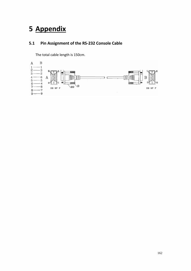
162
5 Appendix
5.1 Pin Assignment of the RS-232 Console Cable
The total cable length is 150cm.

163
5.2 Private MIB
The private MIB can be found in product CD. Compile the private MIB file by
your SNMP tool. The private MIB tree is the same as the web tree. This is easier
to understand and use. If you are not familiar with standard MIB, you can
directly use private MIB to manage/monitor the switch, no need to learn or find
where the OIDs of the commands are.

164
5.3 Revision History
Edition Date Modifications
V1.0 2010/11/30 The first release
V1.1 2013/11/14 Add IPv6, MSTP, QinQ and private VLAN features
Delete the MRI-120-F4G-PSE/8 & MRI-128-F4G-PSE/16

165