Embed Size (px)
Citation preview
Rob Hamann; 12-03-2006 - 1
Koolhoven FK.41 (Desoutter Mk.II) Dujin Models resin kit Monoplane sports plane, taxi plane
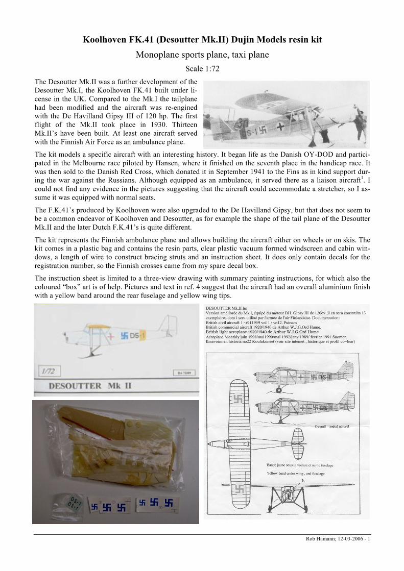
Scale 1:72 The Desoutter Mk.II was a further development of the Desoutter Mk.I, the Koolhoven FK.41 built under li-cense in the UK. Compared to the Mk.I the tailplane had been modified and the aircraft was re-engined with the De Havilland Gipsy III of 120 hp. The first flight of the Mk.II took place in 1930. Thirteen Mk.II’s have been built. At least one aircraft served with the Finnish Air Force as an ambulance plane.
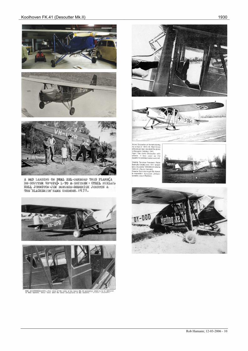
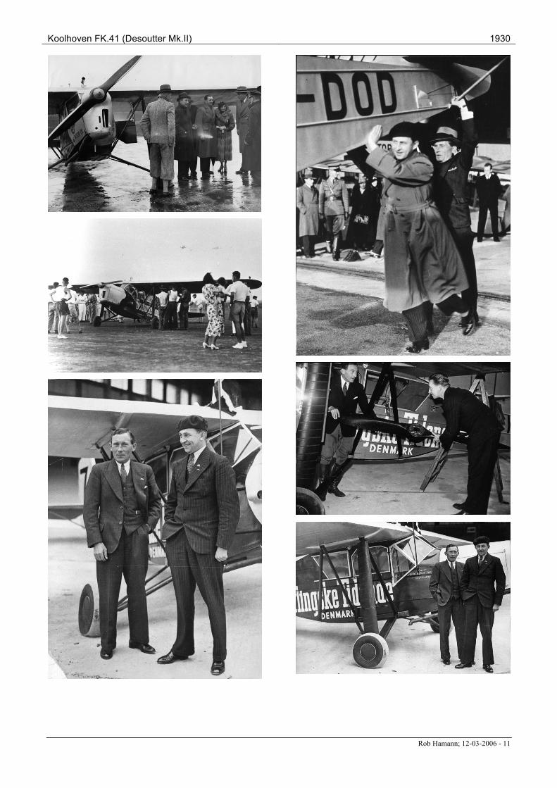
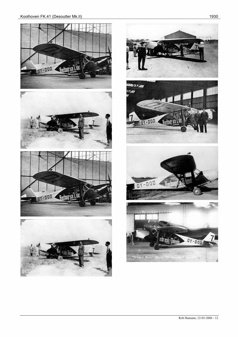
The kit models a specific aircraft with an interesting history. It began life as the Danish OY-DOD and partici-pated in the Melbourne race piloted by Hansen, where it finished on the seventh place in the handicap race. It was then sold to the Danish Red Cross, which donated it in September 1941 to the Fins as in kind support dur-ing the war against the Russians. Although equipped as an ambulance, it served there as a liaison aircraft1. I could not find any evidence in the pictures suggesting that the aircraft could accommodate a stretcher, so I as-sume it was equipped with normal seats.
The F.K.41’s produced by Koolhoven were also upgraded to the De Havilland Gipsy, but that does not seem to be a common endeavor of Koolhoven and Desoutter, as for example the shape of the tail plane of the Desoutter Mk.II and the later Dutch F.K.41’s is quite different.
The kit represents the Finnish ambulance plane and allows building the aircraft either on wheels or on skis. The kit comes in a plastic bag and contains the resin parts, clear plastic vacuum formed windscreen and cabin win-dows, a length of wire to construct bracing struts and an instruction sheet. It does only contain decals for the registration number, so the Finnish crosses came from my spare decal box.
The instruction sheet is limited to a three-view drawing with summary painting instructions, for which also the coloured “box” art is of help. Pictures and text in ref. 4 suggest that the aircraft had an overall aluminium finish with a yellow band around the rear fuselage and yellow wing tips.
Koolhoven FK.41 (Desoutter Mk.II) 1930
Rob Hamann; 12-03-2006 - 2
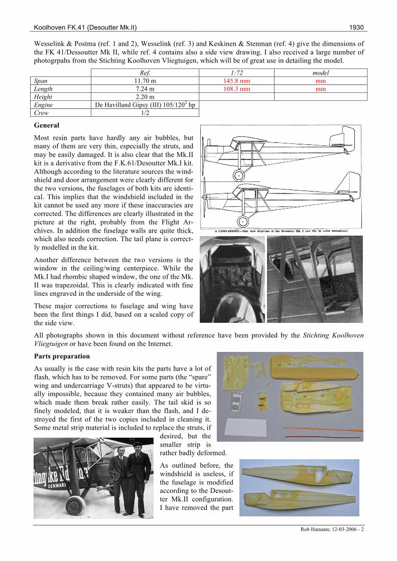
Wesselink & Postma (ref. 1 and 2), Wesselink (ref. 3) and Keskinen & Stenman (ref. 4) give the dimensions of the FK 41/Dessoutter Mk II, while ref. 4 contains also a side view drawing. I also received a large number of photogrpahs from the Stichting Koolhoven Vliegtuigen, which will be of great use in detailing the model.
Ref. 1:72 model Span 11.70 m 145.8 mm mm Length 7.24 m 108.3 mm mm Height 2.20 m Engine De Havilland Gipsy (III) 105/1202 hp Crew 1/2
General
Most resin parts have hardly any air bubbles, but many of them are very thin, especially the struts, and may be easily damaged. It is also clear that the Mk.II kit is a derivative from the F.K.61/Desoutter Mk.I kit. Although according to the literature sources the wind-shield and door arrangement were clearly different for the two versions, the fuselages of both kits are identi-cal. This implies that the windshield included in the kit cannot be used any more if these inaccuracies are corrected. The differences are clearly illustrated in the picture at the right, probably from the Flight Ar-chives. In addition the fuselage walls are quite thick, which also needs correction. The tail plane is correct-ly modelled in the kit.
Another difference between the two versions is the window in the ceiling/wing centerpiece. While the Mk.I had rhombic shaped window, the one of the Mk. II was trapezoidal. This is clearly indicated with fine lines engraved in the underside of the wing.
These major corrections to fuselage and wing have been the first things I did, based on a scaled copy of the side view.
All photographs shown in this document without reference have been provided by the Stichting Koolhoven Vliegtuigen or have been found on the Internet.
Parts preparation
As usually is the case with resin kits the parts have a lot of flash, which has to be removed. For some parts (the “spare” wing and undercarriage V-struts) that appeared to be virtu-ally impossible, because they contained many air bubbles, which made them break rather easily. The tail skid is so finely modeled, that it is weaker than the flash, and I de-stroyed the first of the two copies included in cleaning it. Some metal strip material is included to replace the struts, if
desired, but the smaller strip is rather badly deformed.
As outlined before, the windshield is useless, if the fuselage is modified according to the Desout-ter Mk.II configuration. I have removed the part
Koolhoven FK.41 (Desoutter Mk.II) 1930
Rob Hamann; 12-03-2006 - 3
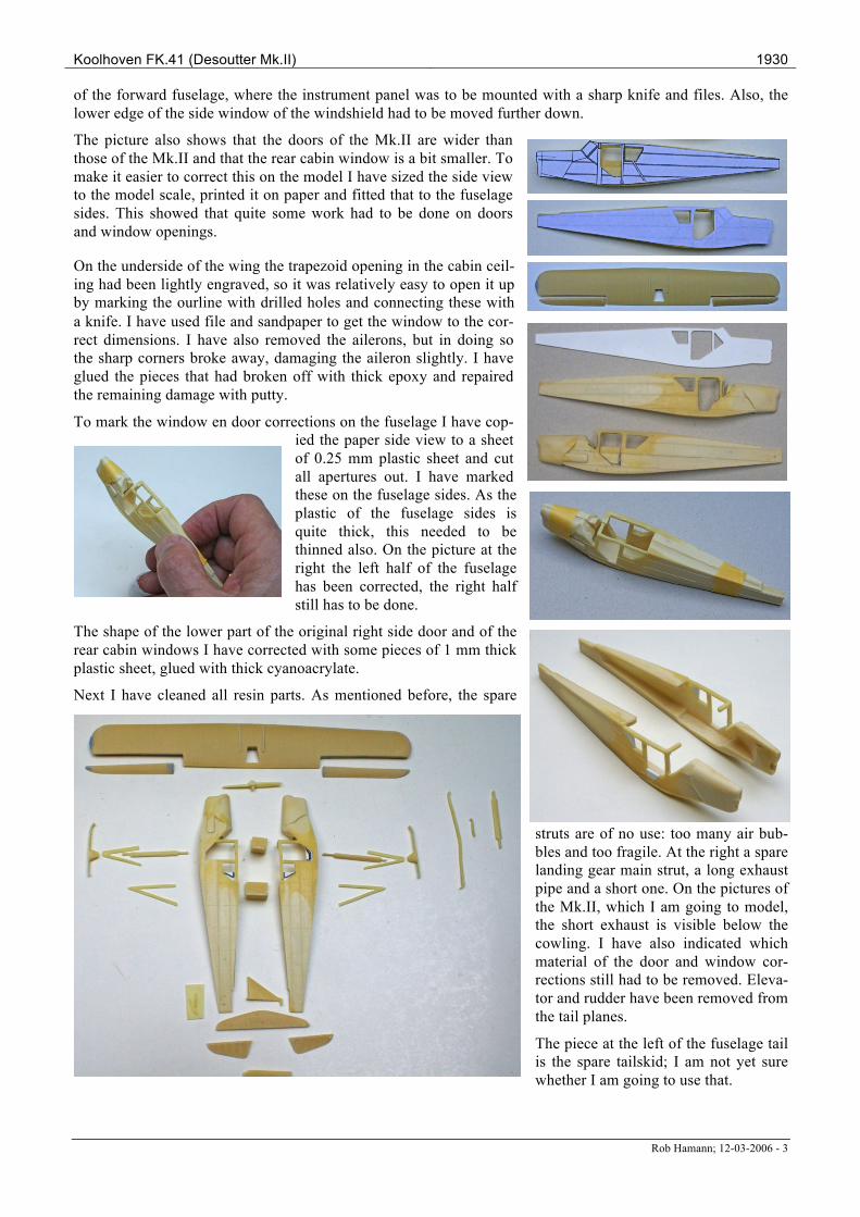
of the forward fuselage, where the instrument panel was to be mounted with a sharp knife and files. Also, the lower edge of the side window of the windshield had to be moved further down.
The picture also shows that the doors of the Mk.II are wider than those of the Mk.II and that the rear cabin window is a bit smaller. To make it easier to correct this on the model I have sized the side view to the model scale, printed it on paper and fitted that to the fuselage sides. This showed that quite some work had to be done on doors and window openings.
On the underside of the wing the trapezoid opening in the cabin ceil-ing had been lightly engraved, so it was relatively easy to open it up by marking the ourline with drilled holes and connecting these with a knife. I have used file and sandpaper to get the window to the cor-rect dimensions. I have also removed the ailerons, but in doing so the sharp corners broke away, damaging the aileron slightly. I have glued the pieces that had broken off with thick epoxy and repaired the remaining damage with putty.
To mark the window en door corrections on the fuselage I have cop-ied the paper side view to a sheet of 0.25 mm plastic sheet and cut all apertures out. I have marked these on the fuselage sides. As the plastic of the fuselage sides is quite thick, this needed to be thinned also. On the picture at the right the left half of the fuselage has been corrected, the right half still has to be done.
The shape of the lower part of the original right side door and of the rear cabin windows I have corrected with some pieces of 1 mm thick plastic sheet, glued with thick cyanoacrylate.
Next I have cleaned all resin parts. As mentioned before, the spare
struts are of no use: too many air bub-bles and too fragile. At the right a spare landing gear main strut, a long exhaust pipe and a short one. On the pictures of the Mk.II, which I am going to model, the short exhaust is visible below the cowling. I have also indicated which material of the door and window cor-rections still had to be removed. Eleva-tor and rudder have been removed from the tail planes.
The piece at the left of the fuselage tail is the spare tailskid; I am not yet sure whether I am going to use that.

Koolhoven FK.41 (Desoutter Mk.II) 1930
Rob Hamann; 12-03-2006 - 4
Fuselage
I have measured the dimensions of the windshield windows and reconstructed its flat projection. I have glued a copy of the drawing on a piece of 0.25 mm plastic sheet, cut it out and scratched the window styles to bend it in shape. Of course that did not work. It broke so I have reinforced it with a piece of tape on the rear side.
Fitting it on the fuselage showed that it had to be adjusted, but after cutting the side windows to size the lower part of the front window appeared to be missing and in general the windscreen was a lot to wide. So I have given up this attempt, and decided to make a mould to produce the windshield. I have used a piece of balsa wood for this purpose and the second woodworking attempt gave an acceptable result. At the bottom of the picture the failed reconstruction attempt. The balsa has been covered with plastic cement to seal the surface.
Forming the plastic windshield was a disaster; none of the ten-odd attempts were successful. I did not manage to create the right combi-
nation of temperature, force and speed in pulling the plastic over the mould. So in the end I have bent a strip of transparent plastic at the measured position of the (parallel) window frame styles with a set of pliers.
I have cut the doors from 0.5 mm plastic, cutting first the outside on size and then cutting the windows out. As usual, they are not exactly equal, but that will not be noticeable later on.
I have cut two bulkheads trial and error on size, as well as a floor from 0.5 mm plastic. The gaps between the rear bulkhead and the sidewalls I have closed with strips of 0.7 x 0.25 mm. The shape and thickness of the back of the pilot seat has been corrected to resemble better the one in the pictures. Even now it is still too big and heavy.
According to the pictures of the Mk.II the cabin floor is almost level to the door threshold, and the tunnel on the floor, where the control cables pass to the tail is not present any more. Also, because of the doors on both sides of the cabin, the elevator trim wheel should have been placed more forward than was the case with the Mk.I, although this is not visible on the pictures. I could not find the push-pull rod for the ailerons, which ran along the right forward cabin frame style for the Mk.I, on the pictures either. As there is in my opinion no other way to get from the control stick to the wing, I have de-cided to incorporate the rod anyhow. The rear bench seems to be provided with buttons, so I have kind of mod-eled these by drilling superficial holes in seat and backrest.
The throttle will be placed at the left side of the forward fu-selage. I have modeled the instrument panel by a piece of 0.25 mm plastic sheet, in which I have drilled five holes to represent the instruments. I have glued it on a piece of 0.13
mm plastic that has been painted black, and scratched the instrument dials in the black paint. Seat belts have been made from light grey and silver painted
narrow strips of Tamyia tape. I have made the rudder bar from 0.25 mm metal wire and the other controls from various pieces of plastic and metal wire.
The interior has been painted light grey (Humbrol 127) and the seats very dark grey (Humbrol 164). I have painted all controls mid grey (Humbrol 126). On the floor of cabin and cockpit I have applied pieces of dark green
Koolhoven FK.41 (Desoutter Mk.II) 1930
Rob Hamann; 12-03-2006 - 5
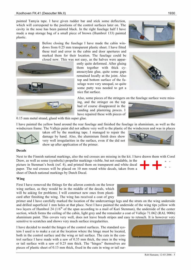
painted Tamyia tape. I have given rudder bar and stick some deflection, which will correspond to the positions of the control surfaces later on. The cavity in the nose has been painted black. In the right fuselage half I have made a map storage bag of a small piece of brown (Humbrol 133) painted plastic.
Before closing the fuselage I have made the cabin win-dows from 0.25 mm transparent plastic sheet. I have fitted these trail and error in the cabin and door apertures and marked them for their location. The fuselage could be closed now. This was not easy, as the halves were appar-
ently quite deformed. After gluing them together with thick cy-anoacrylate glue, quite some gaps remained locally at the joint. Also top and bottom surface of the fu-selage were very unequal, so quite some putty was needed to get a nice flat surface.
Also, some pieces of the stringers on the fuselage surface were miss-ing, and the stringer on the top had of course disappeared in the sanding and plastering proces. I have repaired these with pieces of
0.15 mm metal strand, glued with thin super glue.
I have painted the yellow band around the rear fuselage and finished the fuselage in aluminium, as well as the windscreen frame. The Vallejo paint did not adhere very well to the plastic of the windscreen and was in places
taken off by the masking tape. I managed to repair the damage by hand. Also, the aluminium finish does show very well irregularities in the surface, even if the did not show up after application of the primer.
Decals
Next to the Finnish national markings, also the red crosses are missing in the kit. I have drawn them with Corel Draw, as well as some (symbolic) propeller markings visible, but not readable, in the picture in Stenman’s book (ref. 4), and printed them on transparent and white decal paper. The red crosses will be placed on 10 mm round white decals, taken from a sheet of Dutch national markings by Dutch Decal.
Wing
First I have removed the fittings for the aileron controls on the lower wing surface, as they would be in the middle of the decals, which will be asking for problems; I will construct new ones from plasti-card after finishing the wing. The wing has received a coat of grey primer and I have carefully marked the location of the undercarriage legs and the struts on the wing underside and drilled superficial 1 mm holes at that place. Next I have painted the underside of the wing tips yellow with two layers of Humbrol 24 (1/6th of the span according to a mail of Kari Stenman), the underside of the center section, which forms the ceiling of the cabin, light grey and the remainder a coat of Vallejo 71.062 (RAL 9006) aluminium paint. This covers very well, does not leave brush stripes and easy to retouch. It is however very sensitive to scratches and shows very much surface irregularities.
I have decided to model the hinges of the control surfaces. The standard sys-tem I used is to make a cut at the location where the hinge must be located, both in the control surface and the wing or tail surface. The cuts in the con-trol surface I have made with a saw of 0.35 mm thick, the ones in the wing or tail surface with a saw of 0.25 mm thick. The “hinges” themselves are pieces of plastic sheet of 0.13 mm thick, fixed in the cuts in wing or tail sur-
Koolhoven FK.41 (Desoutter Mk.II) 1930
Rob Hamann; 12-03-2006 - 6
face with thin cyanoacrylate glue. The hinges have been carefully put in shape with a sharp knife and fine sandpaper, as they are paper thin and easy to damage.
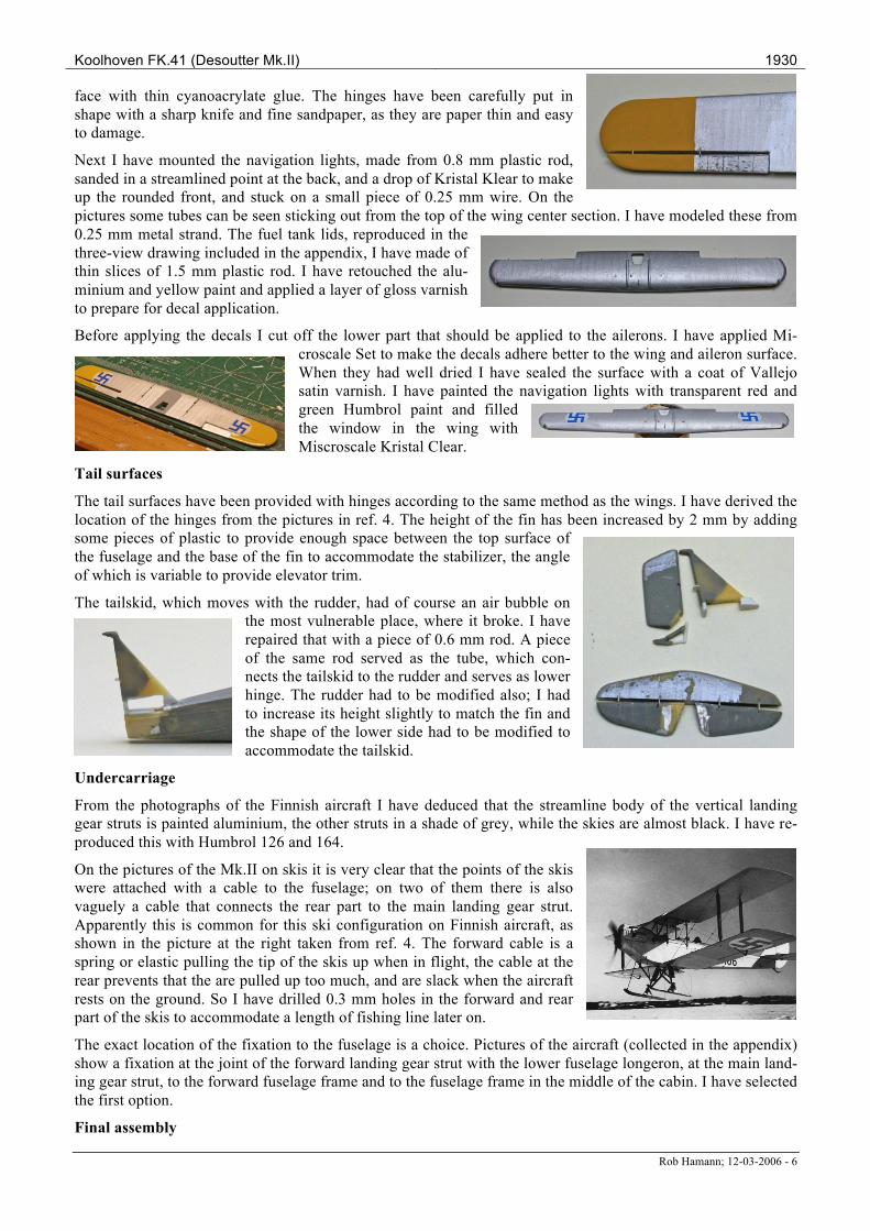
Next I have mounted the navigation lights, made from 0.8 mm plastic rod, sanded in a streamlined point at the back, and a drop of Kristal Klear to make up the rounded front, and stuck on a small piece of 0.25 mm wire. On the pictures some tubes can be seen sticking out from the top of the wing center section. I have modeled these from 0.25 mm metal strand. The fuel tank lids, reproduced in the three-view drawing included in the appendix, I have made of thin slices of 1.5 mm plastic rod. I have retouched the alu-minium and yellow paint and applied a layer of gloss varnish to prepare for decal application.
Before applying the decals I cut off the lower part that should be applied to the ailerons. I have applied Mi-croscale Set to make the decals adhere better to the wing and aileron surface. When they had well dried I have sealed the surface with a coat of Vallejo satin varnish. I have painted the navigation lights with transparent red and green Humbrol paint and filled the window in the wing with Miscroscale Kristal Clear.
Tail surfaces
The tail surfaces have been provided with hinges according to the same method as the wings. I have derived the location of the hinges from the pictures in ref. 4. The height of the fin has been increased by 2 mm by adding some pieces of plastic to provide enough space between the top surface of the fuselage and the base of the fin to accommodate the stabilizer, the angle of which is variable to provide elevator trim.
The tailskid, which moves with the rudder, had of course an air bubble on the most vulnerable place, where it broke. I have repaired that with a piece of 0.6 mm rod. A piece of the same rod served as the tube, which con-nects the tailskid to the rudder and serves as lower hinge. The rudder had to be modified also; I had to increase its height slightly to match the fin and the shape of the lower side had to be modified to accommodate the tailskid.
Undercarriage
From the photographs of the Finnish aircraft I have deduced that the streamline body of the vertical landing gear struts is painted aluminium, the other struts in a shade of grey, while the skies are almost black. I have re-produced this with Humbrol 126 and 164.
On the pictures of the Mk.II on skis it is very clear that the points of the skis were attached with a cable to the fuselage; on two of them there is also vaguely a cable that connects the rear part to the main landing gear strut. Apparently this is common for this ski configuration on Finnish aircraft, as shown in the picture at the right taken from ref. 4. The forward cable is a spring or elastic pulling the tip of the skis up when in flight, the cable at the rear prevents that the are pulled up too much, and are slack when the aircraft rests on the ground. So I have drilled 0.3 mm holes in the forward and rear part of the skis to accommodate a length of fishing line later on.
The exact location of the fixation to the fuselage is a choice. Pictures of the aircraft (collected in the appendix) show a fixation at the joint of the forward landing gear strut with the lower fuselage longeron, at the main land-ing gear strut, to the forward fuselage frame and to the fuselage frame in the middle of the cabin. I have selected the first option.
Final assembly
Koolhoven FK.41 (Desoutter Mk.II) 1930
Rob Hamann; 12-03-2006 - 7
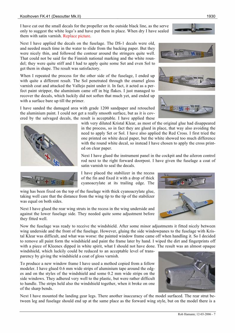
I have cut out the small decals for the propeller on the outside black line, as the serve only to suggest the white logo’s and have put them in place. When dry I have sealed them with satin varnish. Replace picture.
Next I have applied the decals on the fuselage. The DS-1 decals were old, and needed much time in the water to slide from the backing paper. But they were nicely thin, and followed the contour around the stringers quite well. That could not be said for the Finnish national marking and the white roun-del; they were quite stiff and I had to apply quite some Set and even Sol to get them in shape. The result was satisfactory.
When I repeated the process for the other side of the fuselage, I ended up with quite a different result. The Sol penetrated through the enamel gloss varnish coat and attacked the Vallejo paint under it. In fact, it acted as a per-fect paint stripper, the aluminium came off in big flakes. I just managed to recover the decals, which luckily did not soften that much yet, and ended up with a surface bare up till the primer.
I have sanded the damaged area with grade 1200 sandpaper and retouched the aluminium paint. I could not get a really smooth surface, but as it is cov-ered by the salvaged decals, the result is acceptable. I have applied these
with very diluted Kristal Klear, as most of the original glue had disappeared in the process, so in fact they are glued in place, that way also avoiding the need to apply Set or Sol. I have also applied the Red Cross. I first tried the one printed on white decal paper, but the white showed too much difference with the round white decal, so instead I have chosen to apply the cross print-ed on clear paper.
Next I have glued the instrument panel in the cockpit and the aileron control rod next to the right forward doorpost. I have given the fuselage a coat of satin varnish to seal the decals.
I have placed the stabilizer in the recess of the fin and fixed it with a drop of thick cyanoacrylate at its trailing edge. The
wing has been fixed on the top of the fuselage with thick cyanoacrylate glue, taking well care that the distance from the wing tip to the tip of the stabilizer was equal on both sides.
Next I have glued the rear wing struts in the recess in the wing underside and against the lower fuselage side. They needed quite some adjustment before they fitted well.
Now the fuselage was ready to receive the windshield. After some minor adjustments it fitted nicely between wing underside and the front of the fuselage. However, gluing the side windowpanes to the fuselage with Kris-tal Klear was difficult, and what was worse: the painted window frame came off when handling it. So I decided to remove all paint form the windshield and paint the frame later by hand. I wiped the dirt and fingerprints off with a piece of Kleenex dipped in white spirit, what I should not have done. The result was an almost opaque windshield, which luckily could be reduced to an acceptable level of trans-parency by giving the windshield a coat of gloss varnish.
To produce a new window frame I have used a method copied from a fellow modeler. I have glued 0.6 mm wide strips of aluminium tape around the edg-es and on the styles of the windshield and some 0.2 mm wide strips on the side windows. They adhered very well to the plastic, but were rather difficult to handle. The strips held also the windshield together, when it broke on one of the sharp bends.
Next I have mounted the landing gear legs. There another inaccuracy of the model surfaced. The rear strut be-tween leg and fuselage should end up at the same place as the forward wing style, but on the model there is a
Koolhoven FK.41 (Desoutter Mk.II) 1930
Rob Hamann; 12-03-2006 - 8
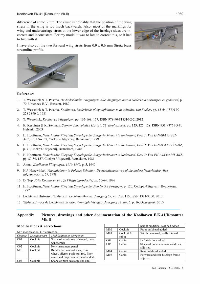
difference of some 3 mm. The cause is probably that the position of the wing struts in the wing is too much backwards. Also, most of the markings for wing and undercarriage struts at the lower edge of the fuselage sides are in-correct and inconsistent. For my model it was to late to correct this, so it had to live with it.
I have also cut the two forward wing struts from 0.9 x 0.6 mm Strutz brass streamline profile.
References 1. T. Wesselink & T. Postma, De Nederlandse Vliegtuigen, Alle vliegtuigen ooit in Nederland ontworpen en gebouwd, p.
70, Unieboek B.V., Bussum, 1982
2. T. Wesselink & T. Postma, Koolhoven, Nederlands vliegtuigbouwer in de schaduw van Fokker, pp. 63-64, ISBN 90 228 3890 0, 1981
3. T. Wesselink, Koolhoven Vliegtuigen, pp. 165-168, 177, ISBN 978-90-818510-2-2, 2012
4. K. Keskinen & K. Stenman, Suomen Ilmavoimien Historia 22, Koulukoneet, pp. 123, 125, 128, ISBN 951-98751-5-8, Helsinki, 2003
5. H. Hooftman, Nederlandse Vliegtuig Encyclopedie, Burgerluchtvaart in Nederland, Deel 1; Van H-NABA tot PH-AEZ, pp. 136-137, Cockpit-Uitgeverij, Bennekom, 1979
6. H. Hooftman, Nederlandse Vliegtuig Encyclopedie, Burgerluchtvaart in Nederland, Deel 2; Van H-NAFA tot PH-AIZ, p. 71, Cockpit-Uitgeverij, Bennekom, 1980
7. H. Hooftman, Nederlandse Vliegtuig Encyclopedie, Burgerluchtvaart in Nederland, Deel 3; Van PH-AJA tot PH-AKZ, pp. 87-89, 157, Cockpit-Uitgeverij, Bennekom, 1981
8. Anon., Koolhoven Vliegtuigen, 1910-1940, p. 5, 1940
9. H.J. Hazewinkel, Vliegtuigbouw in Fokkers Schaduw, De geschiedenis van al die andere Nederlandse vlieg-tuigbouwers, p. 29, 1988
10. D. Top, Frits Koolhoven en zijn Vliegtuigproduktie, pp. 60-64, 1996
11. H. Hooftman, Nederlandse Vliegtuig Encyclopedie, Pander S.4 Postjager, p. 120, Cockpit-Uitgeverij, Bennekom, 1977
12. Luchtvaart Historisch Tijdschrift, Luchtvaartkennis, Jaargang 59, no. 3, p. 115, ISSN 1381-9100, 2010
13. Tijdschrift voor de Luchtvaart historie, Verenigde Vleugels, Jaargang 12, No. 6, p. 16, Oegstgeest, 2010
Appendix Pictures, drawings and other documentation of the Koolhoven F.K.41/Desoutter Mk.II
Modifications & corrections M = modification, C = correction Change Location/part Modification or correction C01 Cockpit Shape of windscreen changed; new
windscreen C02 Cockpit New instrument panel M01 Cockpit Rudder bar, control stick, trim
wheel, aileron push-pull rod, floor cover and map compartment added
C03 Cockpit Shape of pilot seat adjusted and
height modified; seat belt added M02 Cockpit Front bulkhead added M03 Cockpit &
cabin Width increased; walls thinned
C04 Cabin Left side door added C05 Cabin Shape of doors and rear windows
adjusted. M04 Cabin Rear bulkhead added M05 Cabin Forward and rear fuselage frame
adjusted.
Koolhoven FK.41 (Desoutter Mk.II) 1930
Rob Hamann; 12-03-2006 - 9
M06 Cabin Rear bench surface detailed, height adjusted, seatbelts added and floor cover added
M07 Engine com-partment
Cooling opening enlarged, metal bar added
M08 Wing Ceiling widow cut out M09 Wing Ailerons cut loose; hinges added M10 Wing Navigation lights added M11 Wing Tank lids added; center section
tubing added M12 Decals Finnish roundels, red cross roundel
and propeller logos added C06 Tail Fin modified to accommodate ele-
vator trim; trim mechanism added M13 Tail Control surfaces cut loose and
hinges added M14 Tail Rudder enlarged and shape modi-
fied M15 Tail Rudder control cables and cover
plates added M16 Undercarriage Tail skid repaired and modified C07 Fuselage Missing stringers added
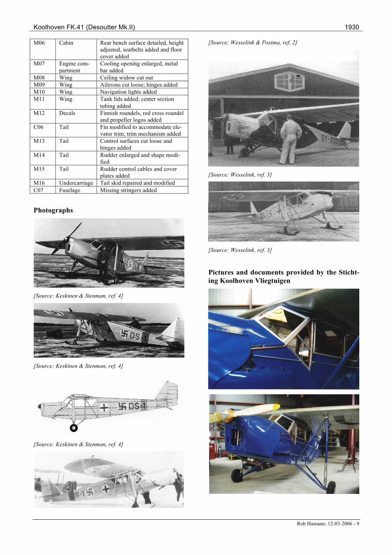
Photographs
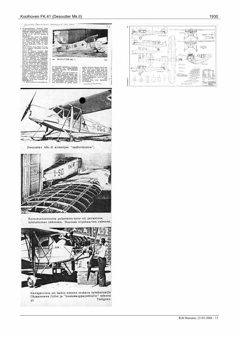
[Source: Keskinen & Stenman, ref. 4]
[Source: Keskinen & Stenman, ref. 4]
[Source: Keskinen & Stenman, ref. 4]
[Source: Wesselink & Postma, ref. 2]
[Source: Wesselink, ref. 3]
[Source: Wesselink, ref. 3]
Pictures and documents provided by the Sticht-ing Koolhoven Vliegtuigen
Koolhoven FK.41 (Desoutter Mk.II) 1930
Rob Hamann; 12-03-2006 - 10
Koolhoven FK.41 (Desoutter Mk.II) 1930
Rob Hamann; 12-03-2006 - 11
Koolhoven FK.41 (Desoutter Mk.II) 1930
Rob Hamann; 12-03-2006 - 12
Koolhoven FK.41 (Desoutter Mk.II) 1930
Rob Hamann; 12-03-2006 - 13
Rob Hamann; 12-03-2006 - 14
1 On all pictures the aircraft is marked as a Red Cross aircraft, although it never served as such according to the references. 2 The Finnish source states a Gipsy Major III engine of 105 hp.