Embed Size (px)
Citation preview

www.goliatinfo.no
Kontroll- og sikkerhetssystem Goliat FPSO
Topologi og kontrollromsløsninger
v/Oddvar Ims

2
Agenda
Agenda
1. Introduction
2. Goliat Network Infrastructure
3. System Topology
4. CCR & ERC

3
GOLIAT FIELD:
- Geostationary FPSO
- 8 subsea templates
- flow lines, risers and umbilical
- 22 wells 11 production
9 water injectors2 gas injectors
- complete oil treatment - power supply from shore - underwater power cableintegrated with onboard powergeneration
- stabilized oil exported by tanker - associated gas re-injected
MAIN CONTRACTS:
- FPSO (Hyundai Heavy Industries)- SPS (Aker)- Offshore Installation (Technip)- Electrical Subsea Cable (ABB)- Onshore Electrification System (Siemens)- Support to project (Sevan)

4
PL229 Goliat Location and Ownership
License awarded in 1997
Present owners•Eni Norge AS (op) 65%
•Statoil Petroleum AS 35%
Production start up Q4 2013
Goliat
5
ABB EICT scope
ABB EICT scope for the Goliat FPSO:
Power from shore Electrical equipment and power system
Instruments & valves
Safety & Control equipment, system applications and interfaces
Telecommunication systems
Remote collaboration facilities
Facilities for condition based maintenance
Industrial networks & Information security infrastructure

6
Goliat Overall Infrastructure
Hammerfest
Stavanger
Supply vessel &
TankersDrilling rig
Goliat FPSO
Fiber
Subsea

7
Goliat Network infrastructure

8
Goliat Network infrastructure

9
Goliat FPSO ICT infrastructure
Physical Network segregation SAS
PIN/utility
Telecom/office
Entertainment/ guest access
Subsea network
Logical segregation using VLAN/VRFs
Firewalls Zones
Centralized infrastructure security Firewalls
Intrusion prevention systems (IPS)
Network Admission Control
Microsoft Active directory
Central backup system
Update servers for Win OS and antivirus
Standardization of ICT equipment

10
SAS Topology
The topology can be summed in three main items
One common HMI and engineering system for PCS and SIS systems
One Control Network containing the PCS, PDCS and PSD systems
One Control Network containing the ESD, HVAC and F&G systems

11
Safety Nodes (SIS Nodes) ESD - Emergency Shutdown System
PSD - Process Shutdown System
F&G - Fire & Gas System
Process Nodes PCS - Process Control System
PDCS - Power Distribution Control System
HMI - Human Machine Interface
Integration of Mechanical Packages into the SAS
High number of control class 1 packages

12
System Topology, Separation Principle
13
System Topology
One Aspect Server at each location (LER and CER)
Connectivity Servers for Control Network and Safety Network at both locations
Independence between Safety and process control achieved
without splitting network.
Two network due to the number of controllers
PSD and PCS on the same network due to large amount of communication between them

14
System
System Description: Physical redundant servers
Each physical server have several virtual servers for the following roles: Redundant Aspect servers – 2 servers (1 pair)
Redundant Connectivity servers – 14 server (7 pairs)
– 5 pairs for process (PDCS, PCS, PSD)
– 2 pairs for safety (F&G, ESD)
Redundant Domain controllers – 2 servers 3 redundant networks (CSA+B, CNA+B, SNA+B)
Other networks are segregated (Electrical etc)
Independent maintenance and backup network
I/O signals (approximately) ESD: 350
PSD: 2000
F&G: 3700 (addressable detectors included)
PCS: 3600 (Hard Wired signals only)

15
CCR
Three Extended Operator Workplaces (EOW-x3)
CAP
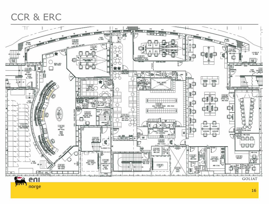
CCR & ERC
16
CCR & ERC
17
EOW-x3 operator console

18
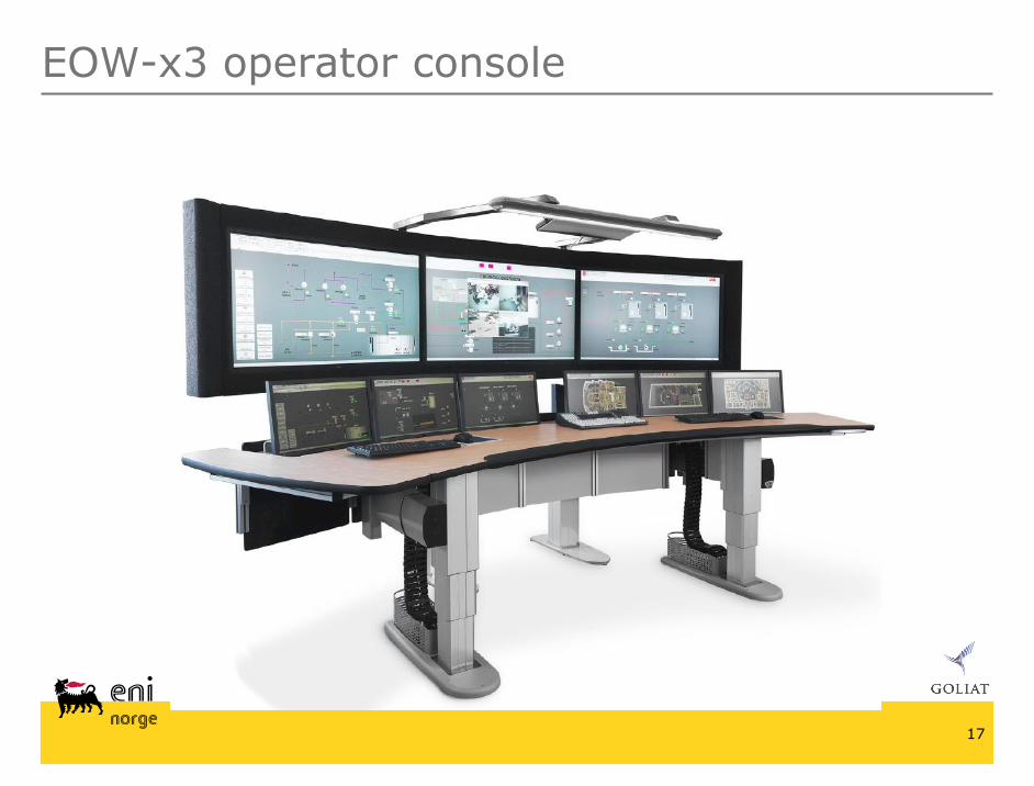
EOW-x3 operator console
Motorized large screen unit containing three 52” industrial LCD panels for 24/7 usage
Six durable 23” wide screen LCD monitors
Remote graphical units enabling removal of all computers away from the operator
Advanced keyboard for multi client handling with hotkeys for frequent 800xA functions
Integrated live video camera system for audio-visual communication
Built in speaker system for public sound
Directional sound system and integrated high frequency dimmable lighting
Motorized holder for each monitor

19
EOW-x3 operator console
The screens are controlled in groups of three
One PC controls the three 52” screens
Two PC’s for the six 23”
All screens have the same resolution: 1920x1080 px
Total resolution for each group is 5760x1080 px
Matrox Remote Graphical Unit
No computers have to be mounted in the EOW-x3 operator desk
20
EOW-x3 operator console
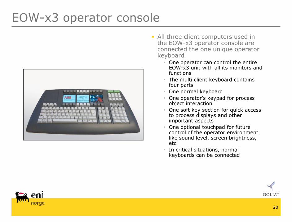
All three client computers used in the EOW-x3 operator console are connected the one unique operator keyboard One operator can control the entire
EOW-x3 unit with all its monitors and functions
The multi client keyboard contains four parts
One normal keyboard
One operator’s keypad for process object interaction
One soft key section for quick access to process displays and other important aspects
One optional touchpad for future control of the operator environment like sound level, screen brightness, etc
In critical situations, normal keyboards can be connected

21
CCR & ERC
x

22
CCR
x

23
CCR WORKSTATION
CCR

24CCR DESK DETAIL
LAYOUT PROPOSAL
CCR

25
ERC – TABLE CLOSED
ERC

26
ERC – TABLE OPEN
ERC

27
ERC
ERC

28
BREAK AREA – ENTRANCE ERC
ERC & Rest area

29
VIEW FROM BREAK AREA
CCR & Test room

30
Questions ?


![EOW LU Tax 2013 Payrolls 1.3.13[1]](https://img.pdfslide.us/doc/110x75/577ce37b1a28abf1038c3c61/eow-lu-tax-2013-payrolls-13131.jpg)