Embed Size (px)
Citation preview

EM SeriesDatagram formatsBase version
Operator manual


EM Series
Multibeam echo sounder
Datagram formats
850--160692 / Rev.G

Note
Kongsberg Simrad AS makes every effort to ensure that the information contained withinthis document is correct. However, our equipment is continuously being improved andupdated, so we cannot assume liability for any errors which may occur.
Warning
The equipment to which this manual applies must only be used for the purpose for whichitwas designed. Improper use ormaintenancemay cause damage to the equipment or injuryto personnel. The usermust be familiar with the contents of the appropriatemanuals beforeattempting to install, operate or maintain the equipment.
Kongsberg Simrad AS disclaims any responsibility for damage or injury caused byimproper installation, use or maintenance of the equipment.
Copyright
E 2002 Kongsberg Simrad AS
The information contained within this document remains the sole property of KongsbergSimrad AS. No part of this document may be copied or reproduced in any form or by anymeans, and the information contained within is not to be communicated to a third party,without the prior written consent of Kongsberg Simrad AS.
KONGSBERG SIMRAD SUBSEAStrandpromenaden 50, P.O.Box 111, N-3191 Horten, NorwayTelephone +47 33 03 40 00 Telefax +47 33 04 44 24
www.kongsberg-simrad.comSupport: [email protected]
Sales: [email protected] emergency number, outside office hours: +47 99 20 38 01
Kongsberg Simrad EM Series
II 850-160692 / G
Table of contents
1 INTRODUCTION 1. . . . . . . . . . . . . . . . . . . . . . . . . . . . . . . . . . . . . . . . .1.1 Purpose 1. . . . . . . . . . . . . . . . . . . . . . . . . . . . . . . . . . . . . . . . . . . . . . . . .1.2 Presentation format 1. . . . . . . . . . . . . . . . . . . . . . . . . . . . . . . . . . . . . . . .
2 INPUT DATAGRAMS 2. . . . . . . . . . . . . . . . . . . . . . . . . . . . . . . . . . . . .2.1 Introduction 2. . . . . . . . . . . . . . . . . . . . . . . . . . . . . . . . . . . . . . . . . . . . . .2.2 Position 3. . . . . . . . . . . . . . . . . . . . . . . . . . . . . . . . . . . . . . . . . . . . . . . . .
Overview 3. . . . . . . . . . . . . . . . . . . . . . . . . . . . . . . . . . . . . . . . . . . . . . .GGA Datagram 5. . . . . . . . . . . . . . . . . . . . . . . . . . . . . . . . . . . . . . . . . .GGK Datagram 7. . . . . . . . . . . . . . . . . . . . . . . . . . . . . . . . . . . . . . . . . .GST Datagram 8. . . . . . . . . . . . . . . . . . . . . . . . . . . . . . . . . . . . . . . . . .VTG Datagram 9. . . . . . . . . . . . . . . . . . . . . . . . . . . . . . . . . . . . . . . . . .Simrad 90 Datagram 10. . . . . . . . . . . . . . . . . . . . . . . . . . . . . . . . . . . . . .Tide input 12. . . . . . . . . . . . . . . . . . . . . . . . . . . . . . . . . . . . . . . . . . . . . .Depth or height input 13. . . . . . . . . . . . . . . . . . . . . . . . . . . . . . . . . . . . .
2.3 Attitude data 14. . . . . . . . . . . . . . . . . . . . . . . . . . . . . . . . . . . . . . . . . . . . .Overview 14. . . . . . . . . . . . . . . . . . . . . . . . . . . . . . . . . . . . . . . . . . . . . . .EM Attitude input format 15. . . . . . . . . . . . . . . . . . . . . . . . . . . . . . . . . .Sperry Mk.39 Attitude input format 17. . . . . . . . . . . . . . . . . . . . . . . . . .HDT format 18. . . . . . . . . . . . . . . . . . . . . . . . . . . . . . . . . . . . . . . . . . . . .SKR80 format 19. . . . . . . . . . . . . . . . . . . . . . . . . . . . . . . . . . . . . . . . . . .
2.4 Clock 20. . . . . . . . . . . . . . . . . . . . . . . . . . . . . . . . . . . . . . . . . . . . . . . . . . .Clock 20. . . . . . . . . . . . . . . . . . . . . . . . . . . . . . . . . . . . . . . . . . . . . . . . . .ZDA format 21. . . . . . . . . . . . . . . . . . . . . . . . . . . . . . . . . . . . . . . . . . . . .
2.5 Sound speed 22. . . . . . . . . . . . . . . . . . . . . . . . . . . . . . . . . . . . . . . . . . . . .Overview 22. . . . . . . . . . . . . . . . . . . . . . . . . . . . . . . . . . . . . . . . . . . . . . .Kongsberg Simrad SSP format 23. . . . . . . . . . . . . . . . . . . . . . . . . . . . . .AML CALC format 25. . . . . . . . . . . . . . . . . . . . . . . . . . . . . . . . . . . . . .AML Smart Sensor format 26. . . . . . . . . . . . . . . . . . . . . . . . . . . . . . . . .
2.6 Depth input from single beam echo sounder 27. . . . . . . . . . . . . . . . . . . .Overview 27. . . . . . . . . . . . . . . . . . . . . . . . . . . . . . . . . . . . . . . . . . . . . . .DBS format 28. . . . . . . . . . . . . . . . . . . . . . . . . . . . . . . . . . . . . . . . . . . . .DPT format 29. . . . . . . . . . . . . . . . . . . . . . . . . . . . . . . . . . . . . . . . . . . . .EA 500 format 30. . . . . . . . . . . . . . . . . . . . . . . . . . . . . . . . . . . . . . . . . . .
2.7 Remote control 31. . . . . . . . . . . . . . . . . . . . . . . . . . . . . . . . . . . . . . . . . . .Overview 31. . . . . . . . . . . . . . . . . . . . . . . . . . . . . . . . . . . . . . . . . . . . . . .
3 OUTPUT DATAGRAMS 33. . . . . . . . . . . . . . . . . . . . . . . . . . . . . . . . . . .

Datagram formats
III850-160692 / G
Introduction 33. . . . . . . . . . . . . . . . . . . . . . . . . . . . . . . . . . . . . . . . . . . . .Depth 35. . . . . . . . . . . . . . . . . . . . . . . . . . . . . . . . . . . . . . . . . . . . . . . . . .Raw range and beam angle 38. . . . . . . . . . . . . . . . . . . . . . . . . . . . . . . . .Seabed image 39. . . . . . . . . . . . . . . . . . . . . . . . . . . . . . . . . . . . . . . . . . .Central beams echogram 41. . . . . . . . . . . . . . . . . . . . . . . . . . . . . . . . . . .Position 43. . . . . . . . . . . . . . . . . . . . . . . . . . . . . . . . . . . . . . . . . . . . . . . .Height 45. . . . . . . . . . . . . . . . . . . . . . . . . . . . . . . . . . . . . . . . . . . . . . . . .Tide 46. . . . . . . . . . . . . . . . . . . . . . . . . . . . . . . . . . . . . . . . . . . . . . . . . . .
3.1 Attitude 47. . . . . . . . . . . . . . . . . . . . . . . . . . . . . . . . . . . . . . . . . . . . . . . . .Heading 48. . . . . . . . . . . . . . . . . . . . . . . . . . . . . . . . . . . . . . . . . . . . . . . .Mechanical transducer tilt 49. . . . . . . . . . . . . . . . . . . . . . . . . . . . . . . . . .Clock 50. . . . . . . . . . . . . . . . . . . . . . . . . . . . . . . . . . . . . . . . . . . . . . . . . .Surface sound speed 51. . . . . . . . . . . . . . . . . . . . . . . . . . . . . . . . . . . . . .Sound speed profile 52. . . . . . . . . . . . . . . . . . . . . . . . . . . . . . . . . . . . . . .Kongsberg Simrad SSP output 53. . . . . . . . . . . . . . . . . . . . . . . . . . . . . .Single beam echo sounder depth 54. . . . . . . . . . . . . . . . . . . . . . . . . . . . .Runtime parameter 55. . . . . . . . . . . . . . . . . . . . . . . . . . . . . . . . . . . . . . .Installation parameters 59. . . . . . . . . . . . . . . . . . . . . . . . . . . . . . . . . . . .

Kongsberg Simrad EM Series
IV 850-160692 / G
Remarks
ReferencesFurther information about the EM Series systems may be found in the following manuals:• EM Series Installation manuals• EM Series Operation manuals• EM Series Maintenance manuals
The readerThis operator manual is intended to be used by the system operator. He/she should beexperienced in the operation of positioning systems, or should have attended a KongsbergSimrad training course.

Datagram formats
V850-160692 / G
Document revisions
Rev Date Written by Checked by Approved by
A 15.04.97 RBr EHa EHa
B 26.11.98 RBr BHL EHa
C 29.12.98 RBr BHL EHa
D 17.07.99 RBr EHa EHa
E 05.05.00 KR EHa EHa
F 05.09.00 RBr EHa EHa
G 10.12.02 RBr EHa EHa
(The original signatures are recorded in the company’s logistic database)

Kongsberg Simrad EM Series
VI 850-160692 / G
Document history(The information on this page is for internal use)
Rev.A Original issue.
Rev.B General update. Unnecessary information removed. Refer to EM160692B.
Rev.C General update. Document 160793 (EM 300 Datagram formats) mergedwith this to create one common source of information for all multibeamecho sounders. Refer to EM 160692C.
Rev.D Remote Control, Raw Range And Beam Angle, Mechanical TransducerTilt, Sound Speed Profile Input and Central Beams Echogram datagramsimplemented. General update with multiple corrections to several inputand output datagrams. Refer to EM 160692D.
Rev.E Layout changed for reading ease.Several minor changes implemented throughout the document, mainlyin the following chapters: 2.1. Introduction and 2.2. Position overview.Minor corrections were implemented on the following datagrams: EA500Format, Remote Control, Height (Remark), Sound Speed Profile andRuntime Parameter (Remarks) and Installation Parameters, AML SmartSensor format, Kongsberg Simrad SSP output.
Rev.F Minor changes made to the following output datagrams: Depth (in Note3), Raw range and beam angle (in Note 1), Surface sound speed output,Runtime parameters and Installation parameters. Also minor changes tolayout to allow for HTML distribution of the document. Refer to EM160692F.
Rev.G Minor changes to output datagrams.

Datagram formats
1850--160692 / G
1 INTRODUCTION
1.1 Purpose
Note The information herein is common for the EM 3000, EM 2000, EM1002, EM 300 and EM 120 multibeam echo sounders. Some of theinformation may not be relevant for your specific system. Pleasedisregard this.
Note The information in this document is not valid for the EM 12, EM100, EM 950 and EM 1000 multibeam echo sounders.
The formats for data input and output to and from the EM Seriesmultibeam echo sounders are described here. The informationgiven here is valid for the Kongsberg Simrad multibeam echosounders introduced after 1995.
Note In order to meet special customer requirements, KongsbergSimrad may have to change the datagram formats described here.The formats presented in this document may therefore be alteredwithout prior notice, although backward compatibility will bemaintained as far as possible. Before software is written inaccordance with this document, it is strongly recommended tocontact Kongsberg Simrad to ensure that the latest version is used,and that any planned changes are taken into account.
1.2 Presentation formatThe format description is according to the NMEA 0183 standardfor ASCII fields, with the ASCII character(s) given as follows:
• “x.x” defines a variable length numerical field, with optionallyincluded decimal point and sign.
• “c--c” defines a variable length field of printable characters.
• “x--x” defines a variable length field of numeric characters.
• “a_ _” defines a fixed length field of alphabetical characters (forexample “aa”= two character long field.
• “x_ _” defines a fixed length field of numeric characters.
For binary fields, the length is given in number of bytes plus “U”for unsigned and “S” for signed data.

Kongsberg Simrad EM Series
2 850--160692 / G
2 INPUT DATAGRAMS
2.1 IntroductionOnly a limited number of input formats from external sensors areaccepted. These are primarily in accordance with the NMEA0183specification, or based upon the principles of that specification.
Note The majority of these formats have not been defined by KongsbergSimrad. Thus, these formats are not controlled by KongsbergSimrad.
Almost all input formats are ASCII. Serial line input on themultibeam echo sounder’s Processing Unit is most common, butsome datagrams - which are not time critical - are interfaced onserial line(s) or Ethernet to the Operator Station.

Datagram formats
3850--160692 / G
2.2 Position
OverviewThe EM Series accepts position data in the following formats:• NMEA 0183 GGA• GGK• SIMRAD 90• With the GGA and GGK datagrams, information contained inNMEA 0183 VGST and VTG datagrams will also be acceptedand used.
• Adatagram format for SonarHead depth is provided for theEM3000 and the EM 2000. Note that the format is the same as thatused by the Paroscientific Digiquartz pressure sensor. Thisformatmay also be used for input of for example varying datumheights or other special height information on all models.
• A datagram format for input of tidal height is provided.The GGA format is given below according to the NMEA 0183version 2.30 description.Additional data at the endof the datagramis accepted to cater for users who need to log additionalinformation than what is provided in the standard format. This isalso supported with the GGK format. The total datagram lengthmust be limited to less than 128 bytes if additional data is included.
Note While such additional data will be logged, it is up to the user toextract the data to whatever use is required in postprocessing.Anyone using this possibility must also be aware that any futurechanges to the GGA or GGK format may require modifications inthe datagrams and hence data decoding.The GGK format was originally defined by the US Army Corpsof Engineers for their tests with kinematic GPS. Trimble’sproprietary version of the format is supported. If any changes to theformat aremade if it becomes part of theNMEAstandard, this willbe implemented.To preserve the inherent accuracy of the kinematic GPS data it isnecessary to correct the data for vessel motion. This requiresaccurate timing synchronisation between the motion sensor andthe GPS receiver. It is therefore imperative that:• the position datagram has a constant and known time delay
or• the time stamp in the datagram is actually the time of theposition fix, that synchronisation to the 1 PPS signal of theGPSreceiver is enabled, and that the system clock has been setcorrectly

Kongsberg Simrad EM Series
4 850--160692 / G
As neither of these conditions may not be possible to achieve witha sufficient accuracy, the application of motion correction isoperator selectable. Motion compensation may be applied to anyposition input, not only kinematic GPS.
In addition to position data from the GGA or GGK datagrams,speed and course over ground from NMEA VTG datagrams mayalso be copied into the position output datagram.These valuesmaybe useful in filtering of the positioning during postprocessing. If aVTG datagram does not follow the GGA or GGK datagram thecourse and speed fields of the output datagrams will be set to theirinvalid values.
The “Standard deviation of semi-major axis of error ellipse” fieldin a NMEA GST datagram may also be copied to the positionoutput datagram as its ”Measure of position fix quality”. It willthen replace the use of theHDOPorDOP field in theGGAorGGKdatagram respectively to derive this field. This must be enabled bythe operator however, and then if the GST datagram does notfollow the GGA or GGK the quality measure field of the outputdatagram will be set to its invalid value.
As an alternative to GGA, the SIMRAD 90 format positiondatagram may be used. The SIMRAD 90 format is intended to bethe format of choice when the positioning system is not astand-alone GPS receiver supplying GGA or GGK formatdatagrams. The SIMRAD 90 format can in addition to globallongitude latitude coordinates also be used for Northing Eastingtype projection coordinates (e.g. UTM).
To cater for applications where the EM 2000 or EM 3000 SonarHead is mounted on a subsea vehicle, the original SIMRAD 90format has been expanded to allow inclusion of the depth of thevehicle in addition to its horizontal position in longitude latitudeor Northing Easting coordinates.
Also for EM2000 and EM3000 applicationswith separate surfaceand underwater positioning systems, the SIMRAD 90 format willallow the underwater position to be provided relative to the vessel,with the vessel surface position given in a separate GGA, GGK orSIMRAD 90 datagram.

Datagram formats
5850--160692 / G
GGA Datagram
Data Description Format Valid range NoteStart identifier = $ Always 24h --- ---Talker identifier aa Capital letters ---Sentence formatter Always GGA, --- ---UTC of position hhmmss.ss, 000000 to
235959.9...---
Latitude in degrees and minutes, plusoptional decimal minutes
llll.ll, 0000 to 9000.0... ---
Latitude --- N/S a, N or S ---Longitude in degrees and minutes, plusoptional decimal minutes
yyyyy.yy, 00000 to 18000.0... ---
Longitude --- E/W a, E or W ---GPS quality indicator x, 0 to 8 1Number of satellites in use xx, 00 to 12 ---HDOP x.x, 0 to 1Antenna altitude re mean sea level (geoid) x.x, --- 2Units of antenna altitude M, --- ---Geoidal separation (sea level re WGS---84) x.x, --- 2Units of geoidal separation M, --- ---Age of differential GPS data x.x, --- ---Differential reference station id xxxx, 0000 to 1023 ---Possible extension of datagram with userdefined data (addition to NMEA format)
c--- ---c --- 3
Checksum *hh --- ---End of sentence delimiter = CRLF Always 0Dh 0Ah --- ---
Note 1
TheHDOP (Horizontal DilutionOf Precision) valuewill be scaledand copied to the ”Measure of position fix quality” field in theposition output datagram. The scale factor depends upon the GPSquality indicator’s value:
• 1 - (SPS or standard GPS) => 1000
• 2 - (differential GPS) => 100
• 3 - (PPS or precise GPS) => 200, but 10 if GGA is treated asRTK. (See Note 2)
• 4 - (kinematic GPS with fixed integers) => 10
• 5 - (kinematic GPS with floating integers) => 50
• 6 - (estimated or dead reckoning mode) => 1000
• 7 - (manual input mode) => 1000
• 8 - (test mode) => 1000, but 10 if GGA is treated as RTK. (SeeNote 2)

Kongsberg Simrad EM Series
6 850--160692 / G
• The ”Measure of position fix quality” field will be set to 65534(largest valid number) if the indicator is zero (non-validposition).
This scaling is used to give at least a relatively correct position fixquality change (in the order of cm) if there are dropouts indifferential, precise or kinematic measurements, although HDOPis not a meter value.
Note 2
When the quality factor is 4 or 5 a height output datagram isautomatically generated, and also if the quality factor is 3 or 8 andthe operator has set the GGA position to be an RTK position. Theheight is the sum of these two fields which are assumed positiveupwards (antenna above geoid).
Note 3
The maximum length of this field should is restricted so that thetotal datagram length is not more than 127 bytes.

Datagram formats
7850--160692 / G
GGK Datagram
Data Description Format Valid range NoteStart identifier = $ Always 24h --- ---Talker identifier aa Capital letters ---Sentence formatter Always GGK, --- ---UTC time of position hhmmss.ss, 000000 to 235959.99... ---UTC date of position MMDDYY, 010100 to 123199 ---Latitude in degrees and minutes, plusoptional decimal minutes
llll.llllll, 0000 to 9000.0... ---
Latitude --- N/S a, N or S ---Longitude in degrees and minutes, plusoptional decimal minutes
yyyyy.yyyyyy, 00000 to 18000.0... ---
Longitude – E/W a, E or W ---GPS quality indicator x, 0 to 3 1Number of satellites in use xx, 00 to 12 ---DOP x.x, 0 --- 1Antenna ellipsoidal height x.x, --- ---Units of antenna ellipsoidal height M, --- ---Possible extension of datagram with userdefined data
c--- ---c --- 2
Checksum *hh --- ---End of sentence delimiter = CRLF Always 0Dh 0Ah --- ---
Note 1
The DOP (Dilution Of Precision) value will be scaled and copiedto the ”Measure of position fix quality” field in the position outputdatagram. The scale factor depends upon the GPS qualityindicator’s value:
• 1 (SPS or standard GPS) => 1000
• 2 (differential GPS) => 100
• 3 (kinematic GPS) => 10
The ”Measure of position fix quality” field will be set to 65534(largest valid number) if the indicator is zero (non-valid position).
This scaling is used to give at least a relatively correct position fixquality change (in cm) if there are dropouts in differential, preciseor kinematic measurements, although DOP is not a meter value.
Note 2
The maximum length of this field should is restricted so that thetotal datagram length is not more than 127 bytes.

Kongsberg Simrad EM Series
8 850--160692 / G
GST Datagram
Data Description Format Valid range NoteStart identifier = $ Always 24h --- ---Talker identifier aa Capital letters ---Sentence formatter Always GST, --- ---UTC time of the GGA or GGK associated with thissentence
hhmmss.ss, 000000 to235959.9...
---
RMS value of the standard deviation of the rangeinputs to the navigation process
x.x, 0 --- ---
Standard deviation of semi---major axis of errorellipse in meters
x.x, 0 --- 1
Standard deviation of semi---minor axis of errorellipse in meters
x.x, 0 --- ---
Orientation of semi---major axis of error ellipse indegrees from true North
x.x, 0 --- ---
Standard deviation of latitude error in meters x.x, 0 --- ---Standard deviation of longitude error in meters x.x, 0 --- ---Standard deviation of altitude error in meters x.x, 0 --- ---Checksum *hh --- ---End of sentence delimiter = CRLF Always 0Dh 0Ah --- ---
Note 1
The term ”standard deviation of error” in the format descriptionimplies that the GST datagram was originally intended to containstatistics. Such a use may invalidate the intended use here, namelyto derive a better quality measure than the HDOP in the GGA orDOP in the GGK datagram. Thus, the GST datagram should onlybe used if one is certain that this field contains the semi-major axisof the error ellipse for the latest fix, and not a statistical measurecalculated over a number of fixes.

Datagram formats
9850--160692 / G
VTG Datagram
Data Description Format Valid range NoteStart identifier = $ Always 24h --- ---Talker identifier aa Capital letters ---Sentence formatter Always VTG, --- ---Course over ground, degrees true x.x,T, 0 to 359.9... 1Course over ground, degrees magnetic x.x,M, 0 to 359.9.. 1Speed over ground, knots x.x,N, 0 --- 1Speed over ground, km/h x.x,K, 0 --- 1Mode indicator a A,D,E,M,S or N ---Checksum *hh --- ---End of sentence delimiter = CRLF Always 0Dh 0Ah --- ---
Note 1
Only true course and the first valid speed field will be used.

Kongsberg Simrad EM Series
10 850--160692 / G
Simrad 90 DatagramData Description Format Length Valid range NoteStart identifier = $ Always 24h 1 --- ---Talker identifier aa 2 Capital letters ---Sentence formatter Always S90, 4 --- ---Date of position DDMMYY, 7 010100 to 311299 ---UTC of position as hour,minute, second, hundredth ofsecond
hhmmssss, 9 00000000 to23595999
---
Latitude in degrees, minutesand decimal minutes
xxxx.xxxx 9 0000.0000 to9999.9999
A
Hemisphere identifier a, 2 N or S ALongitude in degrees, minutesand decimal minutes, or depthin meters
xxxxx.xxxx 10 00000.0000 to18000.0000
A
Hemisphere or depth identifier a, 2 E, W or D ANorthing or range in meters xxxxxxxxx.x, 12 000000000.0 to
999999999.9B
Easting or depth in meters xxxxxxx.x, 10 0000000.0 to9999999.9
B
UTM zone number xx, 3 01 to 60 ---User defined central meridianlongitude or bearing
xxxxx.xxxx 10 00000.0000 to35999.9999
C
Hemisphere or bearingidentifier
a, 2 E, W, or B C
System descriptor x, 2 0 to 7 1Position fix quality indicator x, 2 0 to 9 and A to F 2Speed over ground in m/s xx.x, 5 00.0 to 99.9 3Course over ground in degrees xxx.x 5 000.0 to 359.9 3End of sentence delimiter =,CRLF
Always 2Ch 0Dh 0Ah 3 --- ---
Note 1Value of system descriptor defines content of datagram as follows.(Note that the Kongsberg Simrad EM 12, the EM 950 and the EM1000multibeamecho sounderswill only accept values less than3):- 0 - The position is longitude latitude in global coordinatesgiven in the fields noted A.
- 1 - The position is Northing Easting on the Northernhemisphere given in the fields noted B. If the projection isdefined to beUTMtheUTMzonenumber or a user definablecentralmeridian longitudemay be given in the field notedC.
- 2 -As for system descriptor equal to 1, but the position is onthe Southern Hemisphere.
- 3 - As for system descriptor equal to 0, but in addition thedepth is given in the Easting field noted B.

Datagram formats
11850--160692 / G
- 4 - As for system descriptor equal to 1, but in addition thedepth is given in the longitude field noted A.
- 5 - As for system descriptor equal to 2, but in addition thedepth is given in the longitude field noted A.
- 6 - The position is given relative to the vessel in a polarcoordinate systemwith horizontal range and depth providedin the fields noted B and bearing re true North in the fieldnoted C.
- 7 -As for system descriptor 6, but the bearing is re the vesselcenterline.
Note 2
The position fix quality given in the position output datagramwillbe derived from the quality indicator (this differs from the originaldefinition of the format) as follows (in m):
F E D C B A 9 8 7 6 5 4 3 2 1 0
0.01 0.02 0.05 0.1 0.2 0.5 1 2 5 10 20 50 100 200 500 1000
Note 3
If these fields have valid values they will be copied to equivalentfields in the position output datagram. They may be used infiltering of the positioning during postprocessing. (The originaldefinition of the format had line heading in the course field and itsuse was to orient real-time displays).
Kongsberg Simrad EM Series
12 850--160692 / G
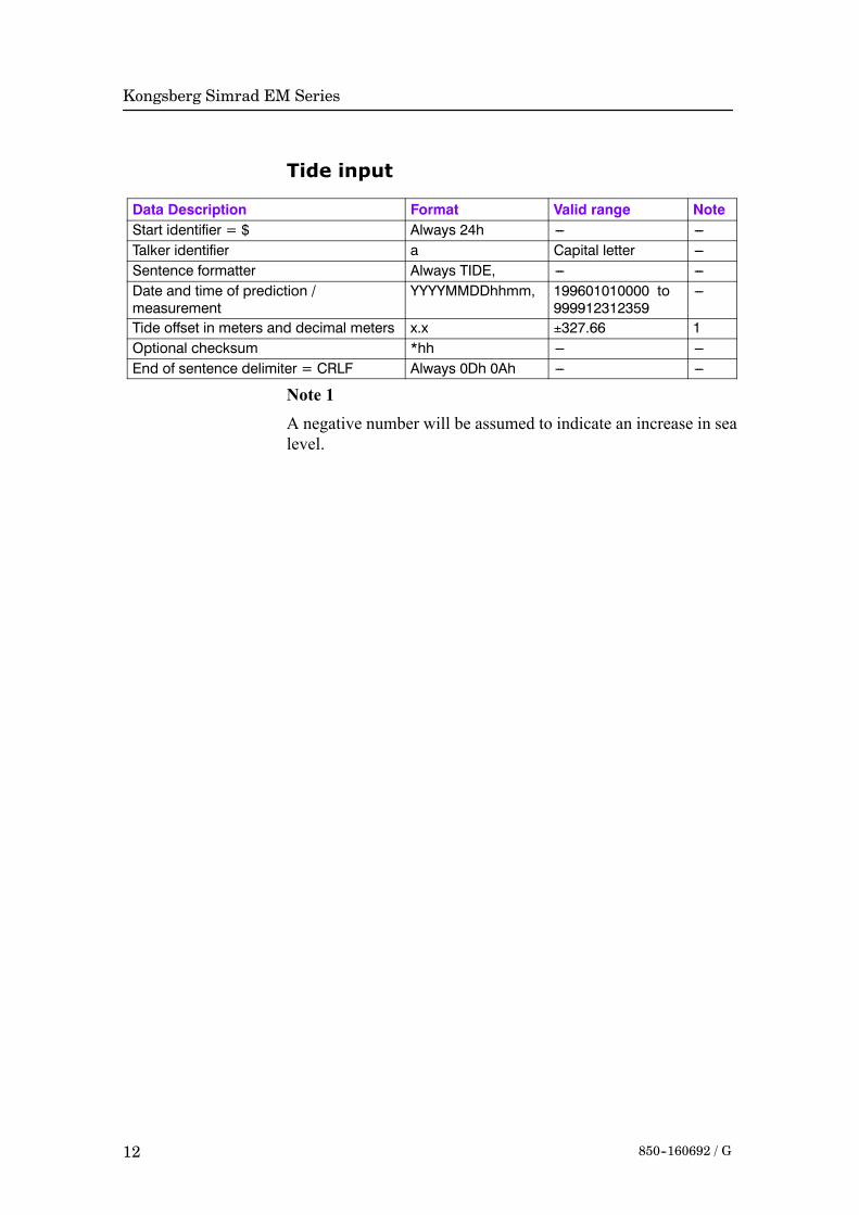
Tide input
Data Description Format Valid range NoteStart identifier = $ Always 24h --- ---Talker identifier a Capital letter ---Sentence formatter Always TIDE, --- ---Date and time of prediction /measurement
YYYYMMDDhhmm, 199601010000 to999912312359
---
Tide offset in meters and decimal meters x.x ±327.66 1Optional checksum *hh --- ---End of sentence delimiter = CRLF Always 0Dh 0Ah --- ---
Note 1
A negative number will be assumed to indicate an increase in sealevel.
Datagram formats
13850--160692 / G
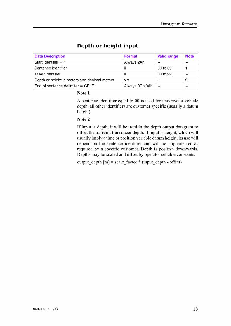
Depth or height input
Data Description Format Valid range NoteStart identifier = * Always 2Ah --- ---Sentence identifier ii 00 to 09 1Talker identifier ii 00 to 99 ---Depth or height in meters and decimal meters x.x --- 2End of sentence delimiter = CRLF Always 0Dh 0Ah --- ---
Note 1
A sentence identifier equal to 00 is used for underwater vehicledepth, all other identifiers are customer specific (usually a datumheight).
Note 2
If input is depth, it will be used in the depth output datagram tooffset the transmit transducer depth. If input is height, which willusually imply a time or position variable datum height, its use willdepend on the sentence identifier and will be implemented asrequired by a specific customer. Depth is positive downwards.Depths may be scaled and offset by operator settable constants:
output_depth [m] = scale_factor * (input_depth - offset)

Kongsberg Simrad EM Series
14 850--160692 / G
2.3 Attitude data
OverviewAttitude data is generally accepted on one or more serial inputport(s) as:
• roll, pitch, heave and heading on one port,
or
• roll, pitch and heave on one port and heading separately onanother port.
The data update rate should be commensurate with the expecteddynamics of the vessel (typically up to 100 Hz).
The acceptable format for roll, pitch, heave and optionally alsoheading is a 10 byte long message originally defined in the EM1000 for use with digital motion sensors. It is supported by thefollowing sensors:
• Applied Analytics POS/MV
• Photokinetics Octans
• Seatex MRU
• Seatex SeaPath
• TSS DMS-05
Headingwill be accepted in theNMEA0183HDT format or in theformat used by the Simrad Robertson SKR80(82) gyrocompass. Acurrent loop to RS-232 converter may then be required. TheLemkuhl LR40(60) Scan Repeater format is also accepted, as it isthe same as that of the SKR80with the exception of an extra statusbyte. Note that if the attitude sensor is capable of reading thegyrocompass and transfer the heading to the attitude sensordatagram (if it does not measure heading itself), this is preferableto interfacing the gyrocompass directly to the system.
Roll, pitch and heading in the Sperry Marine MK-39 MOD2Attitude and Heading Reference System format is also accepted.A second motion sensor must then be used to supply heave.
Attitude data may be supplied frommore than one sensor. All datamay be logged, but only one set as chosen by the operator will beused in real time.

Datagram formats
15850--160692 / G
EM Attitude input format
The EM attitude format is a 10-bytes long message defined asfollows:
• Byte 1: Sync byte 1 = 00h, or Sensor status = 90h-AFh
• Byte 2: Sync byte 2 = 90h
• Byte 3: Roll LSB
• Byte 4: Roll MSB
• Byte 5: Pitch LSB
• Byte 6: Pitch MSB
• Byte 7: Heave LSB
• Byte 8: Heave MSB
• Byte 9: Heading LSB
• Byte 10: Heading MSB
where LSB = least significant byte,MSB = most significant byte.
All data are in 2’s complement binary, with 0.01_ resolution forroll, pitch and heading, and 1 cm resolution for heave.
• Roll is positive with port side up with ±179.99_ valid range
• Pitch is positive with bow up with ±179.99_ valid range
• Heave is positive up with ±9.99 m valid range
• Heading is positive clockwise with 0to 359.99_ valid range.
Non-valid data are assumed when a value is outside the validrange.
How roll is assumed to be measured is operator selectable, eitherwith respect to the horizontal plane (the Hippy 120 or TSSconvention) or to the plane tilted by the given pitch angle (i.e. asa rotation angle around the pitch tilted forward pointing x-axis).The latter convention (called Tate-Bryant in the POS/MVdocumentation) is used inside the system in all data displays andin logged data (a transformation is applied if the roll is given withrespect to the horizontal).
Note that heave is displayed and logged as positive downwards(the sign is changed) including roll and pitch induced lever armtranslation to the system’s transmit transducer.

Kongsberg Simrad EM Series
16 850--160692 / G
This format has previously been usedwith the EM950 and the EM1000 with the first synchronisation byte always assumed to bezero. The sensor manufacturers have been requested to includesensor status in the format using the first synchronisation byte forthis purpose. It is thus assumed that:
• 90h in the first byte indicates a valid measurements with fullaccuracy
• any value from 91h to 99h indicates valid data with reducedaccuracy (decreasing accuracy with increasing number)
• any value from 9Ah to 9Fh indicates non-valid data but normaloperation (for example configuration or calibration mode)
• and any value from A0h to AFh indicates a sensor error status

Datagram formats
17850--160692 / G
Sperry Mk.39 Attitude input formatThe format is 18 bytes long, and it is organised as 9 words. Themost significant byte of a word is transmitted first.
• Word 1 AA55h
• Word 2 Status and time
• Word 3 Heading
• Word 4 Roll
• Word 5 Pitch
• Word 6 Heading rate
• Word 7 Roll rate
• Word 8 Pitch rate
• Word 9 Checksum (MSB) and 1’s complement of checksum(LSB)
All data are in 2’s complement binary. Heading is given within±180_, roll and pitch within ±90_. (Note however that the values+180_ and +90_ are not permitted, as these are one bit too high.)
Heading is measured with reference to true North, and positivewhen the bow points eastwards. Roll is per definition a rotationangle (Tate-Bryant) and positive when the starboard side goes up.Pitch is positive when the bow goes down.

Kongsberg Simrad EM Series
18 850--160692 / G
HDT format
Data Description Format Valid range NoteStart identifier = $ Always 24h --- ---Talker identifier aa Capital letters ---Sentence formatter Always HDT, --- ---Heading, degrees true x.x,T 0 to 359.9... ---Checksum *hh --- ---End of sentence delimiter = CRLF Always 0Dh 0Ah --- ---

Datagram formats
19850--160692 / G
SKR80 formatThe SKR80 sends out a stream of data with four bytes for eachmeasurement. There is one byte for each digit:
• The first byte for the decimal degree (Example: xxx.X)
• The second for the degree (Example: xxX.x)
• The third for the 10’s degree (Example: xXx.x)
• The fourth for the 100’s degree (Example: Xxx.x)
The two uppermost bits of a byte are always zero, the next two bitsgive the digit, 00 for the decimal, 01 for the degree, 10 for the 10’sdegree, and 11 for the 100’s degree. The lowest four bits give thedigit value in 4-bit BCD format. As an example a heading of234.5_ will give the four bytes 05h 14h 23h 32h. The LR40 addsa fifth byte at the end for status with the two upper bits of the statusbyte set to 11 (11000000 for OK, 11001010 for alarm). This statusbyte is ignored.
Kongsberg Simrad EM Series
20 850--160692 / G
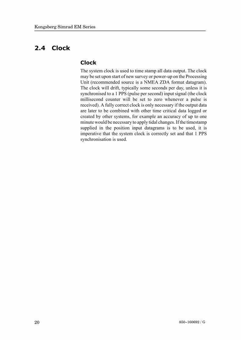
2.4 Clock
ClockThe system clock is used to time stamp all data output. The clockmay be set upon start of new survey or power-up on the ProcessingUnit (recommended source is a NMEA ZDA format datagram).The clock will drift, typically some seconds per day, unless it issynchronised to a 1 PPS (pulse per second) input signal (the clockmillisecond counter will be set to zero whenever a pulse isreceived). A fully correct clock is only necessary if the output dataare later to be combined with other time critical data logged orcreated by other systems, for example an accuracy of up to oneminutewould be necessary to apply tidal changes. If the timestampsupplied in the position input datagrams is to be used, it isimperative that the system clock is correctly set and that 1 PPSsynchronisation is used.

Datagram formats
21850--160692 / G
ZDA format
Data Description Format Valid range NoteStart identifier = $ Always 24h --- ---Talker identifier aa Capital letters ---Sentence formatter Always ZDA, --- ---UTC hhmmss.ss, 000000 to 235959.9... ---Day xx, 01 to +31 ---Month xx, 01 to +12 ---Year xxxx, 0000 to 9999 ---Local zone hours xx, ---13 to +13 1Local zone minutes xx 00 to +59 1Optional checksum *hh --- ---End of sentence delimiter = CRLF Always 0Dh 0Ah --- ---
Note 1
Local zone time is not used. An offset time may be entered by theoperator to get the system clock to show a different time thanUTC.

Kongsberg Simrad EM Series
22 850--160692 / G
2.5 Sound speed
OverviewA sound speed profile may be loaded into the Operator Stationeither on a serial line or on Ethernet. Formats previously usedwithexisting Kongsberg Simrad echo sounders (Kongsberg SimradASCII and Binary SoundVelocity Profile input datagrams) will beaccepted, but since their resolution in depth is limited to 1 m andthe number of entries to 100, a new format given below withoutthese limitations is recommended. This format is also accepted bythe Kongsberg Simrad HIPAP and HPR underwater positioningsystems (but not necessarily vice-versa). Note that a completeprofile may be pieced together from several datagrams and editedwith the Operator Station’s Sound Speed Editor.
The new format is completely in ASCII and allows 9998 entrieswithout limitations in resolution. In addition to depth and soundspeed, it allows input of absorption coefficient, pressure,temperature and salinity or conductivity. The latter parametersmay be used to calculate depth, sound speed and absorptioncoefficient.Use of a depth dependent absorption coefficient allowsa more accurate determination of bottom backscatter strength.
Note that this datagram may also be logged as output, retaininginformation not included in the standard sound speed profileoutput datagram, such as where and when the profile has beentaken.

Datagram formats
23850--160692 / G
Kongsberg Simrad SSP format
Data Description Format Length Valid range NoteStart identifier = $ Always 24h 1 --- ---Talker identifier aa 2 Capital letters ---Datagram identifier Always Sxx, 4 S00to S53 1,2Data set identifier xxxxx, 6 00000 to 65535 ---Number of measurements = N xxxx, 5 0001 to 9999 ---UTC time of data acquisition hhmmss, 7 000000 to 235959 3Day of data acquisition xx, 3 00 to 31 3Month of data acquisition xx, 3 00 to 12 3Year of data acquisition xxxx, 5 0000 to 9999 3N entries of the next 5 fields --- See note 4--- Depth in m from water levelor Pressure in MPa
x.x, 2 --- 0 to 12000.000 to 1.0000
---
--- Sound velocity in m/s x.x, 1 --- 1400 to 1700.00 ------ Temperature in _C x.x, 1 --- ---5 to 45.00 ------ Salinity in parts perthousand or Conductivity inS/m
x.x, 1 --- 0 to 45.000 to 7.000
---
Absorption coefficient in dB/km x.x 0 --- 0 to 200.00 ---Data set delimiter CRLF 2 0Dh 0Ah ---End of repeat cycleLatitude in degrees andminutes, plus optional decimalminutes
llll.ll, Variable 5--- 0000 to 9000.0... 5
Latitude --- N/S a, 2 N or S 5Longitude in degrees andminutes, plus optional decimalminutes
yyyyy.yy, Variable 6--- 00000 to 18000.0... 5
Longitude --- E/W a, 2 E or W 5Atmospheric pressure in MPa x.x, 1 --- 0 to 1.0000 5User given comments c--- ---c Variable --- 5Optional checksum *hh --- --- 6End of datagram delimiter =\CRLF
5Ch 0Dh 0Ah 3 --- ---
Note 1
The datagram identifier identifies what type of data is included.This is shown in the following tablewhereD is depth, P is pressure,S is salinity, C is conductivity, c is sound speed, α is absorptioncoefficients, and L is latitude. The notation c(T,S) indicates forexample that the sound speed is to be calculated from thetemperature and salinity input data. When pressure is used, theatmospheric pressure must be given if the pressure is absolute,

Kongsberg Simrad EM Series
24 850--160692 / G
otherwise the pressure must be given re the sea level and theatmospheric pressure must be zero.
Identifier Input data Data to be usedS00 D, c D, cS10 D, c D, cS11 D, c, α D, c, αS12 D, c, T, S D, c, α(D,T,S,L)S20 D, T, S D, c(D,T,S,L)S21 D, T, S, α D, c(D,T,S,L), αS22 D, T, S D, c(D,T,S,L), α(D,T,S,L)S30 D, T, C D, c(D,T,C,L)S31 D, T, C, α D, c(D,T,C,L), αS32 D, T, C D, c(D,T,C,L), α(D,T,C,L)S40 P, T, S D(P,T,S,L), c(P,T,S,L)S41 P, T, S, α D(P,T,S,L), c(P,T,S,L), αS42 P, T, S D(P,T,S,L), c(P,T,S,L), α(P,T,S,L)S50 P, T, C D(P,T,C,L), c(P,T,C,L)S51 P, T, C, α D(P,T,C,L), c(P,T,C,L), αS52 P, T, C D(P,T,C,L), c(P,T,C,L) , α(P,T,C,L)
Note 2S00 is a special case because then the sound speed profile will betaken into use immediately without further operator intervention.The checksum is thenmandatory andmust be correct. Furthermoreentries for zero depth and a deeper depth than expected during thesurvey must be included.Note 3Note that these fields have fixed length and leading zeros must beused.Note 4The depth or pressure field is always requiredwhile the other fieldsare optional except for those required by the datagram identifier.The field-delimiting commas must always be included even if thefields are empty.Note 5The positions, atmospheric pressure and comment fields areoptional. Note that the option field must not include a \. It isrecommended to include sensor type in the comment field.Note 6The checksum field is calculated between the $ and the *delimitersby exclusive OR’ing of all bytes. The checksum is required fordatagram S00, but is optional for the others.

Datagram formats
25850--160692 / G
AML CALC formatSound speed profile data input in the CALC format is used by theApplied Microsystems Ltd. (AML) Total System Softwarepackage to support AML’s complete range of sensors is alsoaccepted.
This format is an ASCII format with a five line header plus avariable number of lines with data as follows:
Line 1: CALC, sn, date, depth increment, depth display
• sn is the sensor serial number
• date is current date taken from computer
• depth increment is logging depth increment
• depth display is depth units (meters or decibars)
Line 2: AML SOUND VELOCITY PROFILER S/N: xxxxx
Line 3: DATE:xxxxx TIME:xxxxx
• This line gives the Julian date and time at start of sensor logging
Line 4: DEPTH OFFSET(M): xxxx.x
• This line gives the pressure offset at sea level.
Each line of data contains three numbers:
• depth (in meters)
• sound velocity (in m/s)
• temperature (in degrees Celsius)
Line 5: DEPTH(M) VELOCITY (M/S) TEMPERATURE (_C)
The numbers are separated by a space, and each line is terminatedwith a linefeed (LF). The numbers shall all include a decimal point(xxx.x xxxx.x xx.xLF). The data are terminated by a linewith threezeros with two spaces between the zeros (0 0 0).

Kongsberg Simrad EM Series
26 850--160692 / G
AML Smart Sensor formatThe AML Smart SV&P sensor and later the SVPlus sensor maybe used directly for sound speed profile input on serial line to theOperator Station. Both these sensors may also be used to measurethe sound speed at the transducer depth continuously during thesurveying.
A measurement is requested from a smart sensor by issuing theword ’scan’ as four ASCII characters terminated by CR. The replyfrom the SV sensor is a string of ASCII characters:
’S’CRLF xxxx.x CRLF>
where xxxx.x is the measured sound speed in m/s (in bytes 5-11).From the SV&P sensor the received string is:
’S’CRLF ±xxx.xx xxxx.x CRLF>
where the first number is the pressure in decibars relative to thesurface and the second sound speed in m/s (in bytes 13-19).
Smart sensors with autonomous output may also be used, bothP&SV (sound speed with pressure) and T&SP (sound speed withtemperature).
The P&SV format is:
±xxx.xx xxxx.x CRLF
The T&SP format is:
±xx.xxx xxxx.x CRLF
The last field in both of these formats give the sound speed and thefirst field either pressure in decibars or temperature in degreesCelsius.

Datagram formats
27850--160692 / G
2.6 Depth input from single beam echo sounder
OverviewDepth datagrams from a single beam echo sounder are acceptedfor display and logging on the system. The following formats aresupported:
• NMEA 0183 DBS
• NMEA 0183 DPT
• binary datagrams from the Kongsberg Simrad EA 500 echosounder series.

Kongsberg Simrad EM Series
28 850--160692 / G
DBS format
Data Description Format Valid range NoteStart identifier = $ Always 24h --- ---Talker identifier aa Capital letters ---Sentence formatter Always DBS, --- ---Depth in feet x.x,f, 0.1 --- 1Depth in meters x.x,M, 0.1 --- 1Depth in fathoms x.x,F 0.1 --- 1Checksum *hh --- ---End of sentence delimiter = CRLF Always 0Dh 0Ah --- ---
Note 1
The decoding priority will be meter field, feet field and fathomfield with the depth value extracted from the first field with validdata.

Datagram formats
29850--160692 / G
DPT format
Data Description Format Valid range NoteStart identifier = $ Always 24h --- ---Talker identifier aa Capital letters ---Sentence formatter Always DPT, --- ---Depth in meters from the transducer x.x, 0.1 --- ---Offset of transducer from waterline in meters x.x, 0 --- 1Maximum range scale in use x.x --- ---Checksum *hh --- ---End of sentence delimiter = CRLF Always 0Dh 0Ah --- ---
Note 1
A negative value implying that the offset is from the keel shouldnot be used.
Kongsberg Simrad EM Series
30 850--160692 / G
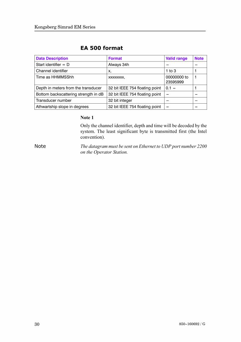
EA 500 format
Data Description Format Valid range NoteStart identifier = D Always 34h --- ---Channel identifier x, 1 to 3 1Time as HHMMSShh xxxxxxxx, 00000000 to
235959991
Depth in meters from the transducer 32 bit IEEE 754 floating point 0.1 --- 1Bottom backscattering strength in dB 32 bit IEEE 754 floating point --- ---Transducer number 32 bit integer --- ---Athwartship slope in degrees 32 bit IEEE 754 floating point --- ---
Note 1
Only the channel identifier, depth and time will be decoded by thesystem. The least significant byte is transmitted first (the Intelconvention).
Note The datagrammust be sent on Ethernet to UDP port number 2200on the Operator Station.

Datagram formats
31850--160692 / G
2.7 Remote control
OverviewA Remote Control datagram has been implemented to allow:• the multibeam echo sounder to start logging on remotecommand.
• the multibeam echo sounder to send out parameter and soundspeed profile datagrams as a response to the remote command.
• the survey line numbers to be set from a remote location.
Note that the parameter and sound speed profile datagrams arealways sent out when logging is started or any changes are madeto the parameters or sound speed. They may also be sent outregularly at operator specified intervals.The datagram currently only allows survey related parameters tobe transferred to the system. It will later be expanded to allowremote setting of all installation parameters, and then basically asa copy of the standard start/stop datagram with identicalconventions with regard to order (which is not important), butrequiring only the parameters actually to be set.
Data Description Format Valid range NoteStart identifier = $ Always 24h --- ---Talker identifier aa Capital letters ---Datagram identifier Rxx, R00 to R20 1EM model number EMX=dddd, --- 2Responsible operator ROP=a--- ---a, --- ---Survey identifier SID=a--- ---a, --- ---Survey line number PLN=d..d, --- ---Survey line identifier (planned line no) PLL=d--- ---d, --- ---Comment COM=a--- ---a --- ---Optional checksum *hh --- ---End of datagram delimiter = \CRLF 5Ch 0Dh 0Ah --- ---
Note 1Rxx defines what action the system is to take with respect topinging and logging of data in addition to changes in theparameters. Note that logging of survey data on local storage is notaffected, this is determined by operator control from the menuonly.• R00 - System to stop pinging (and logging if on)
• R10 - System to stop all logging (but continue or start pinging).

Kongsberg Simrad EM Series
32 850--160692 / G
• R11 - System to start logging on new line to both local andremote
• R12 - System to star logging on new line but only to localstorage
• R13 - System to start logging on new line but only to remote
• R20 - System to send installation parameter datagram andsound speed profile datagrams to remote
Note 2
The EM model number will be required when parameter changesare made with respect to transducer location or system gainsettings.

Datagram formats
33850--160692 / G
3 OUTPUT DATAGRAMS
IntroductionOutput datagrams are usually logged to disk or tape on the EMSeries Operator Station. The output datagrams may also beexported to user provided programs on the Operator Station or onan external Ethernet network using UDP protocol (remotelogging). An NMEA DPT depth datagram may be exported on aserial line.
The output datagrams are mostly in binary format using signed orunsigned integer numberswith lengths of 1, 2 or 4 bytes.All binarydata will presently be big endian.
Note As this is subject to modifications, we recommend that softwarewritten to decode EM Series data includes a check for the byteordering with a provision for byte swapping. Suitable data fieldsto check on are the length field at the start of the datagram, the EMSeries model number field and possibly the date and time fields.
The basic output datagram structure established with the EM 100echo sounder is retained.
• All datagrams (except the NMEA DPT datagram) start withSTX, datagram type and time tag, and end with ETX andchecksum (sum of bytes between STX and ETX). In additionthe total length of the datagram (not including the length field)will precede the STX byte, given as a four byte binary number.
• The length field is only included when logging to tape and/ordisk, but not for datagrams logged to a remote location. Thelength can then be derived from the network software. Systemslogging data remotely should add this length at the start of eachdatagram. This length is required if the data are to be used withKongsberg Simrad post-processing systems.
• The time stamp resolution has been increased to 1 millisecondand now includes the century, but as a consequence the timestamp is now binary and not ASCII as implemented previously.The date is given as 10000*year(4 digits) + 100*month + day,for example 19950226 for February 26, 1995. All date fields inthe output datagrams use this format. A time is usually given (inmilliseconds) from midnight.

Kongsberg Simrad EM Series
34 850--160692 / G
• The datagrams identify the multibeam echo sounder model andits serial number. The system model number is 120 for the EM120, 300 for the EM 300, etc. For the EM 3000D (the dual headsystem) themodel number was originally given as 3002 and theserial number is that of Sonar Head number 1. However in thedepth datagrammodel numbers 3003-3008 are nowused to alsoidentify the actual transmit and sampling frequencies of the twoheads. If only one head is activate on the EM 3000D, it is codedas a single head system.
• Due care has been taken to include all parameters needed inpostprocessing in the relevant datagrams, with a minimum ofdata duplication. Where resolution of a data field is variable, aresolution descriptor is included.
• Invalid data are always identified by the highest positivenumber allowed in a field unless otherwise noted.
• A real-time parameter datagram has been added to enablelogging of parameters not used in postprocessing, but whichmay be important in checking the quality of the logged data, orto allow tracing of reasons for possible malfunctions.
• Attitude data as time continuous records and raw ranges andbeam pointing angles are logged to allow eventualpostprocessing corrections. The logged attitudes are valid at thetransmit transducer, and are corrected for any sensor offsets.

Datagram formats
35850--160692 / G
Depth
Data Description Format Valid range NoteNumber of bytes in datagram 4U --- ---Start identifier = STX (Always 02h) 1U --- ---Type of datagram = D(epth data) (Always 44h) 1U --- ---EM model number(Example: EM 3000 = 3000)
2U --- 4
Date = year*10000 + month*100 + day(Example: Feb 26, 1995 = 19950226)
4U --- ---
Time since midnight in milliseconds(Example: 08:12:51.234 = 29570234)
4U 0 to 86399999 ---
Ping counter (sequential counter) 2U 0 to 65535 ---System serial number 2U 100 --- ---Heading of vessel in 0.01° 2U 0 to 35999 ---Sound speed at transducer in dm/s 2U 14000 to 16000 ---Transmit transducer depth re water level at time ofping in cm
2U 0 to 65536 1
Maximum number of beams possible 1U 48 --- ---Number of valid beams = N 1U 1 to 254 ---z resolution in cm 1U 1 to 254 ---x and y resolution in cm 1U 1 to 254 ---Sampling rate (f) in Hzor
Depth difference between sonar heads in the EM3000D
2U
2S
300 to 30000
---32768 to 32766
3
4
Repeat cycle --- N entries of : 16*N --- ------ Depth (z) from transmit transducer
(unsigned for EM 120 and EM 300)2Sor2U
---32768 to +32766or1 to 65534
2
--- Acrosstrack distance (y) 2S ---32768 to 32766 2--- Alongtrack distance (x) 2S ---32768 to 32766 2--- Beam depression angle in 0.01° 2S ---11000 to 11000 3--- Beam azimuth angle in 0.01° 2U 0 to 56999 3--- Range (one---way travel time) 2U 0 to 65534 3--- Quality factor 1U 0 to 254 5--- Length of detection window (samples/4) 1U 1 to 254 ------ Reflectivity (BS) in 0.5 dB resolution)
(Example: ---20 dB = 216)1S ---128 to +126 ---
--- Beam number 1U 1 to 254 6End of repeat cycleTransducer depth offset multiplier 1S ---1 to +17 1End identifier = ETX (Always 03h) 1U --- ---Check sum of data between STX and ETX 2U --- ---

Kongsberg Simrad EM Series
36 850--160692 / G
Note 1The transmit transducer depth plus the depth offset multipliertimes 65536 cm should be added to the beam depths to derive thedepths re the water line. The depth offset multiplier will usually bezero, except when the EM 2000/3000 Sonar Head is on anunderwater vehicle at a depth larger than 655.36 m. Note that theoffset multiplier will be negative (-1) if the actual heave is largeenough to bring the transmit transducer above the water line. Thismay represent a valid situation, but may also be due to anerroneously set installation depth of either the transducer or thewater line.Note 2The beam data are given re the transmit transducer or sonar headdepth and the horizontal location of the active positioning system’santenna.Heave, roll, pitch, sound speed at the transducer depth andray bending through the water column have been applied. On theEM 1002/2000/3000 the beam depths must be regarded as signedvalues to take into account beams which may be going upwards.On the EM 120/300 the beam depths are always positive and thevalues are therefore unsigned.Note 3The range, beam depression angle (positive downwards and 90_for a vertical beam) and beam azimuth angle (re vessel centerline)are given relative to the transducer (sonar head) at the ping transmittime. Heave, roll, pitch and sound speed at the transducer depthhave been applied, but not ray bending. These values may thus bedirectly used for a new ray bending calculation with a revisedsound speed profile to generate new sounding depths and positionswithout any need for using attitude data. The range resolution intime is the inverse of the range sampling rate (i.e. nominallyequivalent to about 70 µs for the EM 3000).Note that if the data need to be reprocessedwith a new sound speedat the transducer depth or new roll, pitch or heave values, fullreprocessing starting with the raw range and beam angle data isrequired. Attitude data is also required in this reprocessing, andboth these data types will in the future be logged as standard.If the beam azimuth angle has a value larger than 35999, the beampointing angle has replaced the beamdepression angle, and the rawtwo-way travel time has replaced the one-way heave and beamangle corrected travel time. The transmit tilt angle plus 54000 isgiven in the beam azimuth angle field. The use of this datadefinition is available on remote output to a port named as“RawDepth...” for use by other systems which do their ownattitude and sound speed processing.

Datagram formats
37850--160692 / G
Note 4
In an EM 3000D the transmit transducer depth is that of SonarHead number 1, taking into account the depth offset multiplier asdescribed in note 1. The range multiplier is replaced by thedifference in depth between Sonar Head number 1 and 2, i.e. head2 depth is equal to head 1 depth (possibly modified with depthoffset multiplier) plus the depth difference. The range samplingrates inHz of the two heads is given through theEMmodel numberaccording to the following table:
EM model number 3003 3004 3005 3006 3007 3008Sonar Head 1 13956 14293 13956 14621 14293 14621Sonar Head 2 14621 14621 14293 14293 13956 13956
Previously the model number of the EM 3000Dwas given as 3002with head sample rates of 13956 and 14621 Hz respectively. Thehead depths in this case should be assumed to be equal, andalthough the mathematical derivation of final beam depths wouldotherwise be the same as described above, the transmit transducerdepth was not actually exactly that of the sonar heads.
Note 5
The quality number’s upper bit signifies whether amplitude (0) orphase (1) detection has been used. If amplitude the 7 lowest bitsgive the number of samples used in the centre of gravitycalculation. If phase the second highest bit signifies whether asecond (0) or first (1) order curve fit has been applied to determinethe zero phase range, and the 6 lowest bits indicates the quality ofthe fit (actually the normalized variance of the fit re the maximumallowed, i.e. with a lower number the better the fit).
Note 6
Beam 128 is the first beam on the second sonar head in an EM3000D dual head system.

Kongsberg Simrad EM Series
38 850--160692 / G
Raw range and beam angle
Data Description Format Valid range NoteNumber of bytes in datagram 4U --- ---Start identifier = STX (Always 02h) 1U --- ---Type of datagram = F (Always 46h) 1U --- ---EM model number(Example: EM 3000 = 3000)
2U --- ---
Date = year*10000 + month*100 + day(Example: Feb 26, 1995 = 19950226)
4U --- ---
Time since midnight in milliseconds(Example: 08:12:51.234 = 29570234)
4U 0 to 86399999 ---
Ping counter (sequential counter) 2U 0 to 65535 ---System serial number 2U 100 --- ---Maximum number of beams possible 1U 48 --- ---Number of valid beams = N 1U 1 to 254 ---Sound speed at transducer in dm/s 2U 14000 to 16000 ---Repeat cycle --- N entries of : 8*N ------ Beam pointing angle in 0.01° 2S ---11000 to 11000 1--- Transmit tilt angle in 0.01° 2U ---2999 to 2999 1--- Range (two---way travel time) 2U 0 to 65534 1--- Reflectivity (BS) in 0.5 dB resolution 1S ---128 to 126 ------ Beam number 1U 1 to 254 ---End of repeat cycleSpare (Always 0) 1U --- ---End identifier = ETX (Always 03h) 1U --- ---Check sum of data between STX and ETX 2U --- ---
Note 1
The beam pointing angle is positive to port and the transmit tiltangle is positive forwards for a normally mounted system lookingdownwards. The range resolution in time is the inverse of the rangesampling rate given in the depth datagrams.

Datagram formats
39850--160692 / G
Seabed image
Data Description Format Valid range NoteNumber of bytes in datagram 4U --- ---Start identifier = STX (Always 02h) 1U --- ---Type of datagram = S(eabed image data) (Always 53h) 1U --- ---EM model number(Example: EM 3000 = 3000)
2U --- ---
Date = year*10000 + month*100 + day(Example: Feb 26, 1995 = 19950226)
4U --- ---
Time since midnight in milliseconds(Example: 08:12:51.234 = 29570234
4U 0 to 86399999 ---
Ping counter (sequential counter) 2U 0 to 65535 ---System serial number 2U 100 --- ---Mean absorption coefficient in 0.01 dB/km 2U 1 to 20000 1Pulse length in µs 2U 50 --- 1Range to normal incidence used to correct sampleamplitudes in no. of samples
2U 1 to 16384 ---
Start range sample of TVG ramp if not enough dynamicrange (0 else)
2U 0 to 16384 ---
Stop range sample of TVG ramp if not enough dynamicrange (0 else)
2U 0 to 16384 ---
Normal incidence BS in dB (BSN)(Example: ---20 dB = 236)
1S ---50 to 10 ---
Oblique BS in dB (BSO)(Example: ---1 dB = 255)
1S ---60 to 0 ---
Tx beamwidth in 0.1° 2U 1 to 300 ---TVG law crossover angle in 0.1_ 1U 20 to 300 ---Number of valid beams (N) 1U 1 to 254 ---Repeat cycle --- N entries of : 6*N ------ beam index number 1U 0 to 253 2--- sorting direction 1S ---1 or 1 3--- number of samples per beam = Ns 2U 1 --- ------ centre sample number 2U 1 --- 4End of repeat cycleRepeat cycle --- ΣNs entries of: ΣNs ------ Sample amplitudes in 0.5 dB
(Example: ---30 dB = 196)1S ---128 to 126 ---
End of repeat cycleSpare byte if required to get even length (Always 0 ifused)
0---1U --- ---
End identifier = ETX (Always 03h) 1U --- ---Check sum of data between STX and ETX 2U --- ---
Note 1

Kongsberg Simrad EM Series
40 850--160692 / G
These fields have earlier had other definitions.
Note 2
The beam index number is the beam number - 1.
Note 3
The first sample in a beam has lowest range if 1, highest if -1. Notethat the range sampling rate is defined by the sampling rate in thedepth output datagram and that the ranges in the seabed imagedatagram are all two-way from time of transmit to time of receive
Note 4
The centre sample number is the detection point of a beam.

Datagram formats
41850--160692 / G
Central beams echogram
Data Description Format Valid range NoteNumber of bytes in datagram 4U --- ---Start identifier = STX (Always 02h) 1U --- ---Type of datagram = K (Always 4Bh) 1U --- ---EM model number(Example: EM 3000 = 3000)
2U --- ---
Date = year*10000 + month*100 + day(Example: Feb 26, 1995 = 19950226)
4U --- ---
Time since midnight in milliseconds(Example: 08:12:51.234 = 29570234)
4U 0 to86399999
---
Ping counter (sequential counter) 2U 0 to 65535 ---System serial number 2U 100 --- ---Mean absorption coefficient in 0.01 dB/km 2U 1 to 20000 1Pulse length in µs 2U 50 --- 1Range to normal incidence used in TVG 2U 1 to 16384 1Start range sample of TVG ramp if not enough dynamicrange (0 else)
2U 0 to 116384 ---
Stop range sample of TVG ramp if not enough dynamicrange (0 else)
2U 0 to 16384 ---
Normal incidence BS in dB (BSN)(Example: ---20 dB = 236)
1S ---50 to +10 1
Oblique BS in dB (BSO)(Example: ---1 dB = 255)
1S ---60 to 0 1
Tx beamwidth in 0.1° 2U 1 to 300 1TVG law crossover angle in 0.1_ 1U 20 to 300 1Number of included beams (N) 1U 1 --- ---Repeat cycle --- N entries of : 6*N ------ beam index number 1U 0 to 253 2
- spare byte to get even length (Always 0) 1U --- ---
- number of samples per beam = Ns 2U 1 - ---
- start range in samples 2U 1 - 3
End of repeat cycleRepeat cycle --- ΣNs entries of: ΣNs ------ Sample amplitudes in 0.5 dB
(Example: ---30 dB = 196)1S ---128 to
+126---
End of repeat cycleSpare byte if required to get even length (Always 0 if used) 0---1U --- ---End identifier = ETX (Always 03h) 1U --- ---Check sum of data between STX and ETX 2U --- ---

Kongsberg Simrad EM Series
42 850--160692 / G
Note 1
The sample amplitudes are not corrected in accordance with thedetection parameters derived for the ping, as is done for the seabedimage data.
Note 2
The beam index number is the beam number - 1.
Note 3
The range for which the first sample amplitude is valid for thisbeam given as a two-way range. The detection range is given in theraw range and beam angle datagram. Note that data are providedregardless of whether a beam has a valid detection or not.

Datagram formats
43850--160692 / G
Position
Data Description Format Valid range NoteNumber of bytes in datagram 4U --- ---Start identifier = STX (Always 02h) 1U --- ---Type of datagram = P(osition data) (Always 050h) 1U --- ---EM model number(Example: EM 3000 = 3000)
2U --- ---
Date = year*10000 + month*100 + day(Example: Feb 26, 1995 = 19950226)
4U --- ---
Time since midnight in milliseconds(Example: 08:12:51.234 = 29570234)
4U 0 to86399999
---
Position counter (sequential counter) 2U 0 to 65535 ---System / serial number 2U 100 --- ---Latitude in decimal degrees*20000000 (negative ifsouthern hemisphere)(Example: 32°34’ S = ---651333333)
4S --- ---
Longitude in decimal degrees*10000000 (negative ifwestern hemisphere)(Example: 110.25° E = 1102500000 )
4S --- ---
Measure of position fix quality in cm 2U --- 1Speed of vessel over ground in cm/s 2U 0 --- 1Course of vessel over ground in 0.01° 2U 0 to 35999 1Heading of vessel in 0.01° 2U 0 to 35999 ---Position system descriptor 1U 1 to 254 2Number of bytes in input datagram 1U --- 254 ---Position input datagram as received Variable --- 3Spare byte if required to get even length (Always 0 if used) 0---1U --- ---End identifier = ETX (Always 03h) 1U --- ---Check sum of data between STX and ETX 2U --- ---
Note 1These data will be valid only if available as input.Note 2The position system descriptor shows which source this data isfrom and its real-time use by bit coding:• xxxx xx01 - position system no 1• xxxx xx10 – position system no 2• xxxx xx11 – position system no 3• 10xx xxxx – the position system is active, system time has beenused
• 11xx xxxx - the position system is active, input datagram timehas been used

Kongsberg Simrad EM Series
44 850--160692 / G
• xxxx 1xxx – the position may have to be derived from the inputdatagram which is then in SIMRAD 90 format.
Note 3
Complete input datagram except header and tail (such as NMEA0183 $ and CRLF).

Datagram formats
45850--160692 / G
Height
Data Description Format Valid range NoteNumber of bytes in datagram 4U --- ---Start identifier = STX (Always 02h) 1U --- ---Type of datagram = h(eight data) (Always 068h) 1U --- ---EM model number(Example: EM 3000 = 3000)
2U --- ---
Date = year*10000 + month*100 + day(Example: Feb 26, 1995 = 19950226)
4U --- ---
Time since midnight in milliseconds(EXample: 08:12:51.234 = 29570234)
4U 0 to 86399999 ---
Height counter (sequential counter) 2U 0 to 65535 ---System serial number 2U 100 --- ---Height in cm 4S ---4294967296
to 4294967295---
Heigth type 1U 0 to 99 1End identifier = ETX (Always 03h) 1U --- ---Check sum of data between STX and ETX 2U --- ---
Note 1
The height type is as given in the height input datagram unless itis zero. Then the height is derived from theGGKorGGAdatagramand is the height of the water level re the vertical datum (possiblymotion corrected).

Kongsberg Simrad EM Series
46 850--160692 / G
Tide
Data Description Format Valid range Note
Number of bytes in datagram 4U - -Start identifier = STX (Always 02h) 1U - -
Type of datagram = T(ide data) (Always 054h) 1U --- ---
EM model number(Example: EM 3000 = 3000)
2U - -
Date = year*10000 + month*100 + day(Example: Feb 26, 1995 = 19950226)
4U - -
Time since midnight in milliseconds(Example: 08:12:51.234 = 29570234)
4U 0 to86399999
-
Tide counter (sequential counter) 2U 0 to 65535 -System serial number 2U 100 - -Date = year*10000 + month*100 + day (from inputdatagram)(Example: Feb 26, 1995 = 19950226)
4U - -
Time since midnight in milliseconds (from inputdatagram)(Example: 08:12:51.234 = 29570234)
4U 0 to86399999
-
Tidal offset in cm 2S -32768 to32766
-
Spare (Always 0) 1U - -End identifier = ETX (Always 03h) 1U - -Check sum of data between STX and ETX 2U - -

Datagram formats
47850--160692 / G
3.1 AttitudeData Description Format Valid range NoteNumber of bytes in datagram 4U --- ---Start identifier = STX (Always 02h) 1U --- ---Type of datagram = A(ttitude data) (Always 041h) 1U --- ---EM model number(Example: EM 3000 = 3000)
2U --- ---
Date = year*10000 + month*100 + day (at start of datarecord)(Example: Feb 26, 1995 = 19950226)
4U --- ---
Time since midnight in milliseconds (at start of datarecord)(Example: 08:12:51.234 = 29570234)
4U 0 to86399999
---
Attitude counter (sequential counter) 2U 0 to 65535 ---System serial number 2U 100 --- ---Number of entries = N 2U 1 --- ---Repeat cycle --- N entries of: 12*N ------ Time in milliseconds since record start 2U 0 to 65534 ------ Sensor status 2U --- 1--- Roll in 0.01° 2S ---18000 to
18000---
--- Pitch in 0.01° 2S ---18000 to18000
---
--- Heave in cm 2S ---1000 to10000
---
--- Heading in 0.01° 2U 0 to 35999 ---End of repeat cycleSensor system descriptor 1U --- 2End identifier = ETX (Always 03h) 1U --- ---Check sum of data between STX and ETX 2U --- ---
Note 1The sensor status will be copied from the input datagram’s twosync bytes if the sensor uses the EM format, and from the sensor’sstatus word if it is a SperryMk39. See the input format descriptionfor further details.Note 2The sensor system descriptor will show which sensor the data isderived from, andwhich of the sensor’s data have been used in realtime by bit coding:• xx01 xxxx – motion sensor number 1• xx10 xxxx – motion sensor number 2• xxxx xxx1 – heading from the sensor is active• xxxx xx0x – roll from the sensor is active• xxxx x0xx – pitch from the sensor is active• xxxx 0xxx – heave from the sensor is active

Kongsberg Simrad EM Series
48 850--160692 / G
Heading
Data Description Format Valid range NoteNumber of bytes in datagram 4U --- ---Start identifier = STX (Always 02h) 1U --- ---Type of datagram = H(eading data) (Always 048h) 1U --- ---EM model number(Example: EM 3000 = 3000)
2U --- ---
Date = year*10000 + month*100 + day (at start of datarecord)(Example: Feb 26, 1995 = 19950226)
4U --- ---
Time since midnight in milliseconds (at start of datarecord)(System: 08:12:51.234 = 29570234)
4U 0 to86399999
---
Heading counter (sequential counter) 2U 0 to 65535 ---System serial number 2U 100 --- ---Number of entries = N 2U 1 --- ---Repeat cycle --- N entries of: 4*N --- ------ Time in milliseconds since record start 2U 0 to 65534 ------ Heading in 0.01° 2U 0 to 35999 ---End of repeat cycleHeading indicator (active or not) (0 = inactive) 1U --- ---End identifier = ETX (Always 03h) 1U --- ---Check sum of data between STX and ETX 2U --- ---

Datagram formats
49850--160692 / G
Mechanical transducer tilt
Data Description Format Valid range NoteNumber of bytes in datagram 4U ---Start identifier = STX (Always 02h) 1U ---Type of datagram = J (Always 4Ah) 1U ---EM model number(Example: EM 1002 = 1002)
2U ---
Date = year*10000 + month*100 + day (at start of datarecord)(Example: Feb 26, 1995 = 19950226)
4U --- ---
Time since midnight in milliseconds(at start of data record)(Example: 08:12:51.234 = 29570234)
4U 0 to86399999
---
Tilt counter (sequential counter) 2U 0 to 65535 ---System serial number 2U 100 --- ---Number of entries = N 2U 1 --- ---Repeat cycle --- N entries of: 4*N ------ Time in milliseconds since record start 2U 0 to 65534 ------ Tilt in 0.01 degrees 2S ---1499 to
+14991
End of repeat cycleSpare (Always zero) 1U --- ---End identifier = ETX (Always 03h) 1U --- ---Check sum of data between STX and ETX 2U --- ---
Note 1
This tilt angle is the measured mechanical tilt of a hull unit such asthat often supplied with the EM 1002. It is positive when thetransducer is tilted forwards.

Kongsberg Simrad EM Series
50 850--160692 / G
Clock
Data Description Format Valid range Note
Number of bytes in datagram 4U --- ---Start identifier = STX (Always 02h) 1U --- ---Type of datagram = C(lock data) (Always 043h) 1U --- ---EM model number (Example: EM 3000 = 3000) 2U --- ---Date = year*10000 + month*100 + day (of EM clock)(Example: Feb 26, 1995 = 19950226)
4U --- ---
Time since midnight in milliseconds (of EM clock)(Example: 08:12:51.234 = 29570234)
4U 0 to86399999
---
Clock counter (sequential counter) 2U 0 to 65535 ---System serial number 2U 100 --- ---Date = year*10000 + month*100 + day(from external clock input)(Example: Feb 26, 1995 = 19950226)
4U --- ---
Time since midnight in milliseconds(from external clock datagram)(Example: 08:12:51.234 = 29570234)
4U 0 to86399999
---
1 PPS use (active or not) (0 = inactive) 1U --- 1End identifier = ETX (Always 03h) 1U --- ---Check sum of data between STX and ETX 2U --- ---
Note 1
Shows if the system clock is synchronised to an external 1 PPSsignal or not.
Datagram formats
51850--160692 / G
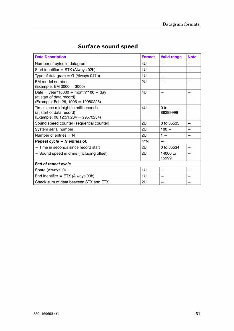
Surface sound speed
Data Description Format Valid range Note
Number of bytes in datagram 4U --- ---Start identifier = STX (Always 02h) 1U --- ---Type of datagram = G (Always 047h) 1U --- ---EM model number(Example: EM 3000 = 3000)
2U --- ---
Date = year*10000 + month*100 + day(at start of data record)(Example: Feb 26, 1995 = 19950226)
4U --- ---
Time since midnight in milliseconds(at start of data record)(Example: 08:12:51.234 = 29570234)
4U 0 to86399999
---
Sound speed counter (sequential counter) 2U 0 to 65535 ---System serial number 2U 100 --- ---Number of entries = N 2U 1 --- ---Repeat cycle --- N entries of: 4*N ------ Time in seconds since record start 2U 0 to 65534 ------ Sound speed in dm/s (including offset) 2U 14000 to
15999---
End of repeat cycleSpare (Always 0) 1U --- ---End identifier = ETX (Always 03h) 1U --- ---Check sum of data between STX and ETX 2U --- ---
Kongsberg Simrad EM Series
52 850--160692 / G
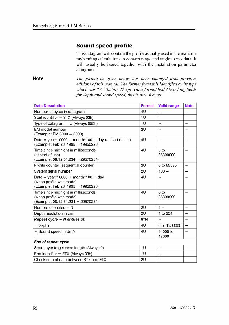
Sound speed profileThis datagramwill contain the profile actually used in the real timeraybending calculations to convert range and angle to xyz data. Itwill usually be issued together with the installation parameterdatagram.
Note The format as given below has been changed from previouseditions of this manual. The former format is identified by its typewhich was “V” (056h). The previous format had 2 byte long fieldsfor depth and sound speed, this is now 4 bytes.
Data Description Format Valid range NoteNumber of bytes in datagram 4U --- ---Start identifier = STX (Always 02h) 1U --- ---Type of datagram = U (Always 055h) 1U --- ---EM model number(Example: EM 3000 = 3000)
2U --- ---
Date = year*10000 + month*100 + day (at start of use)(Example: Feb 26, 1995 = 19950226)
4U --- ---
Time since midnight in milliseconds(at start of use)(Example: 08:12:51.234 = 29570234)
4U 0 to86399999
---
Profile counter (sequential counter) 2U 0 to 65535 ---System serial number 2U 100 --- ---Date = year*10000 + month*100 + day(when profile was made)(Example: Feb 26, 1995 = 19950226)
4U --- ---
Time since midnight in milliseconds(when profile was made)(Example: 08:12:51.234 = 29570234)
4U 0 to86399999
---
Number of entries = N 2U 1 --- ---Depth resolution in cm 2U 1 to 254 ---Repeat cycle --- N entries of: 8*N --- ---
- Depth 4U 0 to 1200000 ---
--- Sound speed in dm/s 4U 14000 to17000
---
End of repeat cycleSpare byte to get even length (Always 0) 1U --- ---End identifier = ETX (Always 03h) 1U --- ---Check sum of data between STX and ETX 2U --- ---

Datagram formats
53850--160692 / G
Kongsberg Simrad SSP outputThis datagram will contain the profile as received as input, and islogged as is to enable use of its data in postprocessing. The realtime use of its data is decided by the operator, the sound speedprofile actually being used is given by the sound speed profileoutput datagram (see above).
Data Description Format Valid range NoteNumber of bytes in datagram 4U --- ---Start identifier = STX (Always 02h) 1U --- ---Type of datagram = W (Always 057h) 1U --- ---EM model number(Example: EM 3000 = 3000)
2U --- ---
Date = year*10000 + month*100 + day(Example: Feb 26, 1995 = 19950226)
4U --- ---
Time since midnight in milliseconds(Example: 08:12:51.234 = 29570234)
4U 0 to86399999
---
SSP counter (sequential counter) 2U 0 to 65535 ---System serial number 2U 100 --- ---Input datagram starting with Sentence formatter and endingwith Comment
Variable --- ---
Spare byte if required to get even length (Always 0 if used ) 0 --- 1U --- ---End identifier = ETX (Always 03h) 1U --- ---Check sum of data between STX and ETX 2U --- ---
Kongsberg Simrad EM Series
54 850--160692 / G
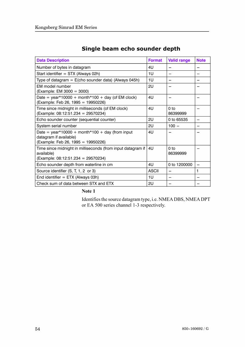
Single beam echo sounder depth
Data Description Format Valid range Note
Number of bytes in datagram 4U --- ---Start identifier = STX (Always 02h) 1U --- ---Type of datagram = E(cho sounder data) (Always 045h) 1U --- ---EM model number(Example: EM 3000 = 3000)
2U --- ---
Date = year*10000 + month*100 + day (of EM clock)(Example: Feb 26, 1995 = 19950226)
4U --- ---
Time since midnight in milliseconds (of EM clock)(Example: 08:12:51.234 = 29570234)
4U 0 to86399999
---
Echo sounder counter (sequential counter) 2U 0 to 65535 ---System serial number 2U 100 --- ---Date = year*10000 + month*100 + day (from inputdatagram if available)(Example: Feb 26, 1995 = 19950226)
4U --- ---
Time since midnight in milliseconds (from input datagram ifavailable)(Example: 08:12:51.234 = 29570234)
4U 0 to86399999
---
Echo sounder depth from waterline in cm 4U 0 to 1200000 ---Source identifier (S, T, 1, 2 or 3) ASCII --- 1End identifier = ETX (Always 03h) 1U --- ---Check sum of data between STX and ETX 2U --- ---
Note 1
Identifies the source datagram type, i.e. NMEADBS,NMEADPTor EA 500 series channel 1-3 respectively.
Datagram formats
55850--160692 / G
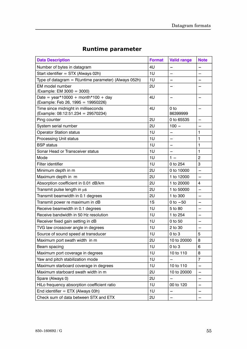
Runtime parameter
Data Description Format Valid range Note
Number of bytes in datagram 4U --- ---Start identifier = STX (Always 02h) 1U --- ---Type of datagram = R(untime parameter) (Always 052h) 1U --- ---EM model number/Example: EM 3000 = 3000)
2U --- ---
Date = year*10000 + month*100 + day(Example: Feb 26, 1995 = 19950226)
4U --- ---
Time since midnight in milliseconds(Example: 08:12:51.234 = 29570234)
4U 0 to86399999
---
Ping counter 2U 0 to 65535 ---System serial number 2U 100 --- ---Operator Station status 1U --- 1Processing Unit status 1U --- 1BSP status 1U --- 1Sonar Head or Transceiver status 1U --- 1Mode 1U 1 --- 2Filter identifier 1U 0 to 254 3Minimum depth in m 2U 0 to 10000 ---Maximum depth in m 2U 1 to 12000 ---Absorption coefficient in 0.01 dB/km 2U 1 to 20000 4Transmit pulse length in µs 2U 1 to 50000 ---Transmit beamwidth in 0.1 degrees 2U 1 to 300 ---Transmit power re maximum in dB 1S 0 to ---50 ---Receive beamwidth in 0.1 degrees 1U 5 to 80 ---Receive bandwidth in 50 Hz resolution 1U 1 to 254 ---Receiver fixed gain setting in dB 1U 0 to 50 ---TVG law crossover angle in degrees 1U 2 to 30 ---Source of sound speed at transducer 1U 0 to 3 5Maximum port swath width in m 2U 10 to 20000 8Beam spacing 1U 0 to 3 6Maximum port coverage in degrees 1U 10 to 110 8Yaw and pitch stabilization mode 1U --- 7Maximum starboard coverage in degrees 1U 10 to 110 ---Maximum starboard swath width in m 2U 10 to 20000 ---Spare (Always 0) 2U --- ---HiLo frequency absorption coefficient ratio 1U 00 to 120 ---End identifier = ETX (Always 03h) 1U --- ---Check sum of data between STX and ETX 2U --- ---

Kongsberg Simrad EM Series
56 850--160692 / G
Note 1The system status will by set bits indicate system faults by bitcoding (a fault may not necessarily be detrimental to systemperformance).The Operator Station status byte is used as follows:• 1xxx xxxx - No reply from the Processing Unit.The Processing Unit status byte is used as follows:• xxxx xxx1 - Communication error with BSP• xxxx xx1x - Communication error with Transceiver or SonarHead
• xxxx x1xx - Attitude not valid for this ping• xxxx 1xxx - Heading not valid for this ping• xxx1 xxxx - System clock has not been set since power on• xx1x xxxx - External trigger signal not detected• x1xx xxxx - Hull unit not respondingA set bit in the BSP status byte indicates an internalcommunication problem.On the EM2000 and EM3000 problemswith the high speed data uplink are specifically indicated asfollows:• xxxxxxx1 -EM2000, EM3000 andSonarHead no 1 on theEM3000D
• xxx1 xxxx - Sonar Head no 2 on the EM 3000DThe BSP status byte is used as follows by the EM 3000:• xxxxxxx1 -Ping rejected due to errors in receiveddata onBSP1• xxxx xx1x - Too much seabed image data on BSP1• xxxx x1xx - Invalid command received by BSP1• xxx1xxxx -Ping rejected due to errors in receiveddata onBSP2• xx1x xxxx - Too much seabed image data on BSP2• x1xx xxxx - Invalid command received by BSP2The Sonar Head status byte is used as follows by the EM 2000 andEM 3000:• xxxx xxx1 - Temperature too high on Sonar Head 1• xxxx xx1x - Data link failure on Sonar Head 1• xxxx x1xx - Voltages out of range on Sonar Head 1• xxx1 xxxx - Temperature too high on Sonar Head 2 of EM3000D
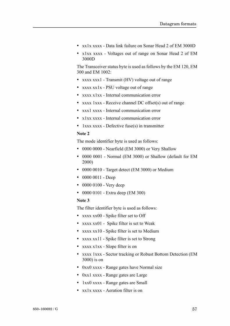
Datagram formats
57850--160692 / G
• xx1x xxxx - Data link failure on Sonar Head 2 of EM 3000D
• x1xx xxxx - Voltages out of range on Sonar Head 2 of EM3000D
The Transceiver status byte is used as follows by the EM 120, EM300 and EM 1002:• xxxx xxx1 - Transmit (HV) voltage out of range
• xxxx xx1x - PSU voltage out of range
• xxxx x1xx - Internal communication error
• xxxx 1xxx - Receive channel DC offset(s) out of range
• xxx1 xxxx - Internal communication error
• x1xx xxxx - Internal communication error
• 1xxx xxxx - Defective fuse(s) in transmitter
Note 2The mode identifier byte is used as follows:• 0000 0000 - Nearfield (EM 3000) or Very Shallow
• 0000 0001 - Normal (EM 3000) or Shallow (default for EM2000)
• 0000 0010 - Target detect (EM 3000) or Medium
• 0000 0011 - Deep
• 0000 0100 - Very deep
• 0000 0101 - Extra deep (EM 300)
Note 3The filter identifier byte is used as follows:
• xxxx xx00 - Spike filter set to Off
• xxxx xx01 - Spike filter is set to Weak
• xxxx xx10 - Spike filter is set to Medium
• xxxx xx11 - Spike filter is set to Strong
• xxxx x1xx - Slope filter is on
• xxxx 1xxx - Sector tracking or Robust Bottom Detection (EM3000) is on
• 0xx0 xxxx - Range gates have Normal size
• 0xx1 xxxx - Range gates are Large
• 1xx0 xxxx - Range gates are Small
• xx1x xxxx - Aeration filter is on

Kongsberg Simrad EM Series
58 850--160692 / G
• x1xx xxxx - Interference filter is on
Note 4
The used absorption coefficient should be derived from the seabedimage or central beams echogram datagram if it is automaticallyupdated with changing depth.
Note 5
The sound speed (at the transducer depth) source identifier is usedas follows :
• 0000 0000 - From real time sensor
• 0000 0001 - Manually entered by operator
• 0000 0010 - Interpolated from currently used sound speedprofile
Note 6
The beamspacing identifier is used as follows:
• 0000 0000 - Determined by beamwidth (FFT beamformer ofEM 3000)
• 0000 0001 - Equidistant
• 0000 0010 - Equiangle
• 0000 0011 - Equiangle around nadir, equidistant in between
Note 7
The yaw and pitch stabilization identifier is set as follows:
• xxxx xx00 - No yaw stabilization
• xxxx xx01 -Yaw stabilization to survey line heading (Not used)
• xxxx xx10 - Yaw stabilization to mean vessel heading
• xxxx xx11 - Yaw stabilization to manually entered heading
• 1xxx xxxx - Pitch stabilization is on.
Note 8
Port swath width and coverage was in earlier versions the sum ofport and starboard

Datagram formats
59850--160692 / G
Installation parametersThis datagram is an ASCII datagram except for the header whichis formed as in all other output datagrams. The datagram is issuedas a start datagram when logging is switched on and as a stopdatagram when logging is turned off, i.e. at the start and end of asurvey line. It may also be sent to a remote port as an informationdatagram. It is usually followedby a sound speed profile datagram.In the datagram all ASCII fields start with a unique three characteridentifier followed by “=”. This should be usedwhen searching fora specific field as the position of a field within the datagram is notguaranteed. The number or character part following is in a variableformat with a minus sign and decimal point if needed, and with “,”as the field delimiter. The formatmay at any time later be expandedwith the addition of new fields at any place in the datagram.For the EM 3000 the transducer 1 data are for the Sonar Head andthe transducer 2 data are for the second Sonar Head of an EM3000D. For other new EM systems with separate transmit andreceive transducers, transducer 1 refers to the transmit transducer,and transducer 2 refers to the receive transducer.
Data Description Example Format Valid range NoteNumber of bytes in datagram --- 4U --- 1Start identifier = STX Always 02h 1U --- ---Type of datagram = I or i(nstallationparameters) or r(emote information)
Start = 049hStop = 069hRemote info =70h
1U --- ---
EM model number EM 3000 =3000
2U --- ---
Date = year*10000 + month*100 + day Feb 26, 1995 =19950226
4U --- ---
Time since midnight in milliseconds 08:12:51.234 =29570234
4U 0 to86399999
---
Survey line number --- 2U 0 to 65534 ---System serial number --- 2U 100 --- ---Serial number of second sonar head --- 2U 100 --- ---Water line vertical location in m WLZ=x.x, ASCII --- ---System main head serial number SMH=x.x, ASCII 100 --- 1Hull Unit HUN=x ASCII 0 or 1 ---Hull Unit tilt offset HUT=x.x ASCII --- ---Transducer 1 vertical location in m S1Z=x.x, ASCII --- ---Transducer 1 along location in m S1X=x.x, ASCII --- ---Transducer 1 athwart location in m S1Y=x.x, ASCII --- ---Transducer 1 heading in degrees S1H=x.x, ASCII --- ---Transducer 1 roll in degrees re horizontal S1R=x.x, ASCII --- ---

Kongsberg Simrad EM Series
60 850--160692 / G
Data Description NoteValid rangeFormatExampleTransducer 1 pitch in degrees S1P=x.x, ASCII --- ---Transducer 1 no of modules S1N=x--- ---x, ASCII --- ---Transducer 2 vertical location in m S2Z=x.x, ASCII --- ---Transducer 2 along location in m S2X=x.x, ASCII --- ---Transducer 2 athwart location in m S2Y=x.x, ASCII --- ---Transducer 2 heading in degrees S2H=x.x, ASCII --- ---Transducer 2 roll in degrees re horizontal S2R=x.x, ASCII --- ---Transducer 2 pitch in degrees S2P=x.x, ASCII --- ---Transducer 2 no of modules S2N=x--- ---x, ASCII --- ---System (sonar head 1) gain offset GO1=x.x, ASCII --- ---Sonar head 2 gain offset GO2=x.x, ASCII --- ---Outer beam offset OBO=x.x ASCII --- ---High/Low Frequency Gain Difference FGD=x.x ASCII --- ---Transmitter (sonar head no1) softwareversion
TSV=c--- ---c, ASCII --- 2
Receiver (sonar head 2) software version RSV=c--- ---c, ASCII --- 2BSP software version BSV=c--- ---c, ASCII --- 2Processing unit software version PSV=c--- ---c, ASCII --- 2Operator station software version OSV=c--- ---c, ASCII --- 2Datagram format version DSV=c--- ---c, ASCII --- 2Depth sensor time delay in millisec DSD=x--- ---x, ASCII --- ---Depth sensor offset DSO=x.x, ASCII --- ---Depth sensor scale factor DSF=x.x, ASCII --- ---Depth sensor heave DSH=aa, ASCII IN or NI 3Active position system number APS=x, ASCII 0 to 2 7Position system 1 motion compensation P1M=x, ASCII 0 or 1 4Position system 1 time stamp used P1T=x, ASCII 0 or 1 5Position system 1 vertical location in m P1Z=x.x, ASCII --- ---Position system 1 along location in m P1X=x.x, ASCII --- ---Position system 1 athwart location in m P1Y=x.x, ASCII --- ---Position system 1 time delay in seconds P1D=x.x, ASCII --- ---Position system 1 geodetic datum P1G=c--- ---c, ASCII --- ---Position system 2 motion compensation P2M=x, ASCII 0 or 1 4Position system 2 time stamp use P2T=x, ASCII 0 or 1 5Position system 2 vertical location in m P2Z=x.x, ASCII --- ---Position system 2 along location in m P2X=x.x, ASCII --- ---Position system 2 athwart location in m P2Y=x.x, ASCII --- ---Position system 2 time delay in seconds P2D=x.x, ASCII --- ---Position system 2 geodetic datum P2G=c--- ---c, ASCII --- ---Position system 3 motion compensation P3M=x, ASCII 0 or 1 4Position system 3 time stamp use P3T=x, ASCII 0 or 1 5
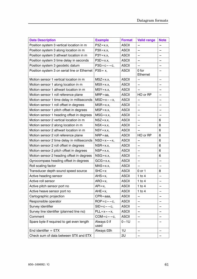
Datagram formats
61850--160692 / G
Data Description NoteValid rangeFormatExamplePosition system 3 vertical location in m P3Z=x.x, ASCII --- ---Position system 3 along location in m P3X=x.x, ASCII --- ---Position system 3 athwart location in m P3Y=x.x, ASCII --- ---Position system 3 time delay in seconds P3D=x.x, ASCII --- ---Position system 3 geodetic datum P3G=c--- ---c, ASCII --- ---Position system 3 on serial line or Ethernet P3S= x, ASCII 0 for
Ethernet---
Motion sensor 1 vertical location in m MSZ=x.x, ASCII --- ---Motion sensor 1 along location in m MSX=x.x, ASCII --- ---Motion sensor 1 athwart location in m MSY=x.x, ASCII --- ---Motion sensor 1 roll reference plane MRP=aa, ASCII HO or RP ---Motion sensor 1 time delay in milliseconds MSD=x--- ---x, ASCII --- ---Motion sensor 1 roll offset in degrees MSR=x.x, ASCII --- ---Motion sensor 1 pitch offset in degrees MSP=x.x, ASCII --- ---Motion sensor 1 heading offset in degrees MSG=x.x, ASCII --- ---Motion sensor 2 vertical location in m NSZ=x.x, ASCII --- 6Motion sensor 2 along location in m NSX=x.x, ASCII --- 6Motion sensor 2 athwart location in m NSY=x.x, ASCII --- 6Motion sensor 2 roll reference plane NRP=aa, ASCII HO or RP 6Motion sensor 2 time delay in milliseconds NSD=x--- ---x, ASCII --- 6Motion sensor 2 roll offset in degrees NSR=x.x, ASCII --- 6Motion sensor 2 pitch offset in degrees NSP=x.x, ASCII --- 6Motion sensor 2 heading offset in degrees NSG=x.x, ASCII --- 6Gyrocompass heading offset in degrees GCG=x.x, ASCII --- ---Roll scaling factor MAS=x.x, ASCII --- ---Transducer depth sound speed source SHC=x ASCII 0 or 1 8Active heading sensor AHS=x, ASCII 1 to 4 ---Active roll sensor ARO=x, ASCII 1 to 4 ---Active pitch sensor port no API=x, ASCII 1 to 4 ---Active heave sensor port no AHE=x, ASCII 1 to 4 ---Cartographic projection CPR=aaa, ASCII --- ---Responsible operator ROP=c--- ---c, ASCII --- ---Survey identifier SID=c--- ---c, ASCII --- ---Survey line identifier (planned line no) PLL=x--- ---x, ASCII --- ---Comment COM=c--- ---c, ASCII --- ---Spare byte if required to get even length Always 0 if
used0---1U --- ---
End identifier = ETX Always 03h 1U --- ---Check sum of data between STX and ETX 2U --- ---

Kongsberg Simrad EM Series
62 850--160692 / G
Note 1
Serial number of head no 2 if that head is the only one in use withthe EM3000D, otherwise the serial number of head no 1 in the EM3000D or the only head in the EM 3000.
Note 2
Aversion number is given as 3 alphanumerical fields separated bydecimal points, plus date as yymmdd (for example 3.02.11991124).
Note 3
IN = the heave of an underwater vehicle is presumed to bemeasured by the vehicle’s depth sensor and the heave sensor inputis not used by system.
Note 4
1 = the positions are motion compensated
0 = the positions are not motion compensated
Note 5
0 = the system has used its own time stamp for the valid time ofthe positions
1 = the system has used the time stamp of the position inputdatagram (external time).
Note 6
If entries for a secondmotion sensor are not included although twosensors are being used, they are presumed to have the sameparameters.
Note 7
Position system number -1.
Note 8
0 = Transducer depth sound speed is used as the initial entry thesound speed profile used in the raytracing calculations.1 = Transducer depth sound speed is NOT used for raytracingcalculations.Note that the source of the sound speed at the transducer depth (andthis sound speed is always used to calculate beam pointing anglesif required) is logged in the runtime datagram.

Datagram formats
63850-160692 / G
Blank page

Kongsberg Simrad EM Series
64 850-160692 / G
Blank page