Embed Size (px)
Citation preview

MSTMini SSBL Transponder
(Cd6424b)
Instruction Manual


857-164457
MSTMini SSBL Transponder
Instruction Manual
This is the Instruction manual for the Kongsberg MaritimeMini SSBL Transponder.
If the transponder includes a lithium battry:
Warning Due to safety rules, the safety information fortransponder and transponder battery must beread before handling transponders or separatetransponder batteries. Refer to:- Safety information for transponder andtransponder battery chapter on page 9.
About this document
Rev Date Written by Checked by Approved by
I 13.02.2012 IJG HAA SER
Updated Spare Parts chapter with P/N 499-215473 for Chassis w/rechargable battery MST.
© 2012 Kongsberg Maritime AS. All rights reserved.No part of this work covered by the copyright hereon may be reproduced or otherwisecopied without prior permission from Kongsberg Maritime AS.The information contained in this document is subject to change without prior notice.Kongsberg Maritime AS shall not be liable for errors contained herein, or for incidentalor consequential damages in connection with the furnishing, performance, or use of thisdocument.
Strandpromenaden 50P.O.Box 111N-3191 Horten,Norway

Instruction Manual
III857-164457 / I
Contents
INTRODUCTION 1. . . . . . . . . . . . . . . . . . . . . . . . . . . . . . . . . . . . . . . . . . . . . .
Manual contents 1. . . . . . . . . . . . . . . . . . . . . . . . . . . . . . . . . . . . . . . . . . . . . . .List of abbreviations 1. . . . . . . . . . . . . . . . . . . . . . . . . . . . . . . . . . . . . . . . . . . .How to handle a transponder 1. . . . . . . . . . . . . . . . . . . . . . . . . . . . . . . . . . . . .
Important information 1. . . . . . . . . . . . . . . . . . . . . . . . . . . . . . . . . . . . .Operation 2. . . . . . . . . . . . . . . . . . . . . . . . . . . . . . . . . . . . . . . . . . . . . . .Maintenance 2. . . . . . . . . . . . . . . . . . . . . . . . . . . . . . . . . . . . . . . . . . . .Pressure relief valves 2. . . . . . . . . . . . . . . . . . . . . . . . . . . . . . . . . . . . . .
General description 2. . . . . . . . . . . . . . . . . . . . . . . . . . . . . . . . . . . . . . . . . . . . .Available transponders 3. . . . . . . . . . . . . . . . . . . . . . . . . . . . . . . . . . . . . . . . . .Transducers 4. . . . . . . . . . . . . . . . . . . . . . . . . . . . . . . . . . . . . . . . . . . . . . . . . . .Beam patterns 4. . . . . . . . . . . . . . . . . . . . . . . . . . . . . . . . . . . . . . . . . . . . . . . . .Accessories 4. . . . . . . . . . . . . . . . . . . . . . . . . . . . . . . . . . . . . . . . . . . . . . . . . . .Transponder model identification principles 5. . . . . . . . . . . . . . . . . . . . . . . . .
Model name 5. . . . . . . . . . . . . . . . . . . . . . . . . . . . . . . . . . . . . . . . . . . . .Model number 5. . . . . . . . . . . . . . . . . . . . . . . . . . . . . . . . . . . . . . . . . . .Options 5. . . . . . . . . . . . . . . . . . . . . . . . . . . . . . . . . . . . . . . . . . . . . . . .
TECHNICAL SPECIFICATION 6. . . . . . . . . . . . . . . . . . . . . . . . . . . . . . . .
Common specifications 6. . . . . . . . . . . . . . . . . . . . . . . . . . . . . . . . . . . . . . . . .General 6. . . . . . . . . . . . . . . . . . . . . . . . . . . . . . . . . . . . . . . . . . . . . . . .Connectors 6. . . . . . . . . . . . . . . . . . . . . . . . . . . . . . . . . . . . . . . . . . . . . .Power supply 6. . . . . . . . . . . . . . . . . . . . . . . . . . . . . . . . . . . . . . . . . . . .Transmitter 6. . . . . . . . . . . . . . . . . . . . . . . . . . . . . . . . . . . . . . . . . . . . .Receiver 6. . . . . . . . . . . . . . . . . . . . . . . . . . . . . . . . . . . . . . . . . . . . . . . .Responder operation 6. . . . . . . . . . . . . . . . . . . . . . . . . . . . . . . . . . . . . .
Source level and receiver sensitivity 7. . . . . . . . . . . . . . . . . . . . . . . . . . . . . . .MST 319 7. . . . . . . . . . . . . . . . . . . . . . . . . . . . . . . . . . . . . . . . . . . . . . . . . . . . .MST 324 7. . . . . . . . . . . . . . . . . . . . . . . . . . . . . . . . . . . . . . . . . . . . . . . . . . . . .MST 342 7. . . . . . . . . . . . . . . . . . . . . . . . . . . . . . . . . . . . . . . . . . . . . . . . . . . . .Floating collars 8. . . . . . . . . . . . . . . . . . . . . . . . . . . . . . . . . . . . . . . . . . . . . . . .
1000 / 2000 m floating collar 8. . . . . . . . . . . . . . . . . . . . . . . . . . . . . . .4000 m floating collar 8. . . . . . . . . . . . . . . . . . . . . . . . . . . . . . . . . . . . .
Battery charger 8. . . . . . . . . . . . . . . . . . . . . . . . . . . . . . . . . . . . . . . . . . . . . . . .
MST
IV 857-164457 / I
SAFETY INFORMATION FOR TRANSPONDER ANDTRANSPONDER BATTERY 9. . . . . . . . . . . . . . . . . . . . . . . . . . . . . . . . . . . .
Introduction 9. . . . . . . . . . . . . . . . . . . . . . . . . . . . . . . . . . . . . . . . . . . . . . . . . .Product identification 9. . . . . . . . . . . . . . . . . . . . . . . . . . . . . . . . . . . . . . . . . . .
Product name 9. . . . . . . . . . . . . . . . . . . . . . . . . . . . . . . . . . . . . . . . . . . .Battery design 9. . . . . . . . . . . . . . . . . . . . . . . . . . . . . . . . . . . . . . . . . . .Battery chemistry 9. . . . . . . . . . . . . . . . . . . . . . . . . . . . . . . . . . . . . . . .Battery cell manufacturers/types 10. . . . . . . . . . . . . . . . . . . . . . . . . . . . .
Hazards identification 10. . . . . . . . . . . . . . . . . . . . . . . . . . . . . . . . . . . . . . . . . . .General 10. . . . . . . . . . . . . . . . . . . . . . . . . . . . . . . . . . . . . . . . . . . . . . . .Danger of explosions 10. . . . . . . . . . . . . . . . . . . . . . . . . . . . . . . . . . . . . .Noxious gases 11. . . . . . . . . . . . . . . . . . . . . . . . . . . . . . . . . . . . . . . . . . .
First-aid measures 12. . . . . . . . . . . . . . . . . . . . . . . . . . . . . . . . . . . . . . . . . . . . . .Fire-fighting measures 12. . . . . . . . . . . . . . . . . . . . . . . . . . . . . . . . . . . . . . . . . .Personals protection 13. . . . . . . . . . . . . . . . . . . . . . . . . . . . . . . . . . . . . . . . . . . .Handling 13. . . . . . . . . . . . . . . . . . . . . . . . . . . . . . . . . . . . . . . . . . . . . . . . . . . . .
Introduction 13. . . . . . . . . . . . . . . . . . . . . . . . . . . . . . . . . . . . . . . . . . . . .Recovering a ’functioning’ transponder 13. . . . . . . . . . . . . . . . . . . . . . .Recovering a ’failing’ transponder 13. . . . . . . . . . . . . . . . . . . . . . . . . . .Handling a heated or self-heated transponder 14. . . . . . . . . . . . . . . . . . .Handling a transponder if the relief valve opens 14. . . . . . . . . . . . . . . .Opening a transponder with defect/possible defect battery 15. . . . . . . .Opening a ’functioning’ transponder 15. . . . . . . . . . . . . . . . . . . . . . . . .Handling heated or self-heated separate battery 15. . . . . . . . . . . . . . . . .
Storage 16. . . . . . . . . . . . . . . . . . . . . . . . . . . . . . . . . . . . . . . . . . . . . . . . . . . . . .Ecological information 16. . . . . . . . . . . . . . . . . . . . . . . . . . . . . . . . . . . . . . . . . .Disposal considerations 17. . . . . . . . . . . . . . . . . . . . . . . . . . . . . . . . . . . . . . . . .Transport information 18. . . . . . . . . . . . . . . . . . . . . . . . . . . . . . . . . . . . . . . . . . .
OPERATION 19. . . . . . . . . . . . . . . . . . . . . . . . . . . . . . . . . . . . . . . . . . . . . . . . . .General 19. . . . . . . . . . . . . . . . . . . . . . . . . . . . . . . . . . . . . . . . . . . . . . . . . . . . . .Activate the transponder 19. . . . . . . . . . . . . . . . . . . . . . . . . . . . . . . . . . . . . . . . .Deactivate the transponder/responder 20. . . . . . . . . . . . . . . . . . . . . . . . . . . . . .Changing the transponder channel 20. . . . . . . . . . . . . . . . . . . . . . . . . . . . . . . . .
Principles 20. . . . . . . . . . . . . . . . . . . . . . . . . . . . . . . . . . . . . . . . . . . . . . .External power supply and / or responder trig 21. . . . . . . . . . . . . . . . . . . . . . . .Pre-deployment checks 22. . . . . . . . . . . . . . . . . . . . . . . . . . . . . . . . . . . . . . . . . .Deployment 22. . . . . . . . . . . . . . . . . . . . . . . . . . . . . . . . . . . . . . . . . . . . . . . . . .Recovery checks 22. . . . . . . . . . . . . . . . . . . . . . . . . . . . . . . . . . . . . . . . . . . . . . .Pressure relief valves 23. . . . . . . . . . . . . . . . . . . . . . . . . . . . . . . . . . . . . . . . . . .
Operation of pressure relief valves 23. . . . . . . . . . . . . . . . . . . . . . . . . . .Floating collar 24. . . . . . . . . . . . . . . . . . . . . . . . . . . . . . . . . . . . . . . . . . . . . . . . .
General 24. . . . . . . . . . . . . . . . . . . . . . . . . . . . . . . . . . . . . . . . . . . . . . . .Floating collar for MST 319 / MST 324 24. . . . . . . . . . . . . . . . . . . . . . .Floating collar for MST 342 25. . . . . . . . . . . . . . . . . . . . . . . . . . . . . . . .
Instruction Manual
V857-164457 / I
BATTERIES 26. . . . . . . . . . . . . . . . . . . . . . . . . . . . . . . . . . . . . . . . . . . . . . . . . . .Battery lifetime 26. . . . . . . . . . . . . . . . . . . . . . . . . . . . . . . . . . . . . . . . . . . . . . . .
NiMH 26. . . . . . . . . . . . . . . . . . . . . . . . . . . . . . . . . . . . . . . . . . . . . . . . .Lithium 26. . . . . . . . . . . . . . . . . . . . . . . . . . . . . . . . . . . . . . . . . . . . . . . .
Battery charger 27. . . . . . . . . . . . . . . . . . . . . . . . . . . . . . . . . . . . . . . . . . . . . . . .Charging the battery 27. . . . . . . . . . . . . . . . . . . . . . . . . . . . . . . . . . . . . . . . . . . .
Safety 27. . . . . . . . . . . . . . . . . . . . . . . . . . . . . . . . . . . . . . . . . . . . . . . . . .Charge procedure 28. . . . . . . . . . . . . . . . . . . . . . . . . . . . . . . . . . . . . . . .
Replacement of the battery pack 30. . . . . . . . . . . . . . . . . . . . . . . . . . . . . . . . . .Battery storage 30. . . . . . . . . . . . . . . . . . . . . . . . . . . . . . . . . . . . . . . . . . . . . . . .
CONFIGURATION 31. . . . . . . . . . . . . . . . . . . . . . . . . . . . . . . . . . . . . . . . . . . . .HPR 400 channels 31. . . . . . . . . . . . . . . . . . . . . . . . . . . . . . . . . . . . . . . .HPR 300 channels 32. . . . . . . . . . . . . . . . . . . . . . . . . . . . . . . . . . . . . . . .HPR 400 channels and positioning frequencies table 33. . . . . . . . . . . . .HPR 300 channels and positioning frequencies table 33. . . . . . . . . . . . .
Functions 34. . . . . . . . . . . . . . . . . . . . . . . . . . . . . . . . . . . . . . . . . . . . . . . . . . . .Transponder function 34. . . . . . . . . . . . . . . . . . . . . . . . . . . . . . . . . . . . .Responder function 34. . . . . . . . . . . . . . . . . . . . . . . . . . . . . . . . . . . . . . .External power function 35. . . . . . . . . . . . . . . . . . . . . . . . . . . . . . . . . . .
Source level (Tx power) and sensitivity (Rx gain) adjustment 36. . . . . . . . . . .General 36. . . . . . . . . . . . . . . . . . . . . . . . . . . . . . . . . . . . . . . . . . . . . . . .To reduce the factory pre-set Tx power 36. . . . . . . . . . . . . . . . . . . . . . . .To reduce the factory pre-set Rx gain 36. . . . . . . . . . . . . . . . . . . . . . . . .
MAINTENANCE 37. . . . . . . . . . . . . . . . . . . . . . . . . . . . . . . . . . . . . . . . . . . . . . .General 37. . . . . . . . . . . . . . . . . . . . . . . . . . . . . . . . . . . . . . . . . . . . . . . . . . . . . .O-rings 37. . . . . . . . . . . . . . . . . . . . . . . . . . . . . . . . . . . . . . . . . . . . . . . . . . . . . .Dismantling the transponder 37. . . . . . . . . . . . . . . . . . . . . . . . . . . . . . . . . . . . .Replacement of the transducer 39. . . . . . . . . . . . . . . . . . . . . . . . . . . . . . . . . . . .Replacement of the main board 40. . . . . . . . . . . . . . . . . . . . . . . . . . . . . . . . . . .Replacement of the interface board 41. . . . . . . . . . . . . . . . . . . . . . . . . . . . . . . .Replacement of the battery pack 41. . . . . . . . . . . . . . . . . . . . . . . . . . . . . . . . . .Transponder assembly 41. . . . . . . . . . . . . . . . . . . . . . . . . . . . . . . . . . . . . . . . . .Transducer handling 42. . . . . . . . . . . . . . . . . . . . . . . . . . . . . . . . . . . . . . . . . . . .Lubrication of the external connector 42. . . . . . . . . . . . . . . . . . . . . . . . . . . . . .
MAIN PARTS 43. . . . . . . . . . . . . . . . . . . . . . . . . . . . . . . . . . . . . . . . . . . . . . . . . .Overview 43. . . . . . . . . . . . . . . . . . . . . . . . . . . . . . . . . . . . . . . . . . . . . . . . . . . .Circuit boards 44. . . . . . . . . . . . . . . . . . . . . . . . . . . . . . . . . . . . . . . . . . . . . . . . .
Overview 44. . . . . . . . . . . . . . . . . . . . . . . . . . . . . . . . . . . . . . . . . . . . . . .Main board 44. . . . . . . . . . . . . . . . . . . . . . . . . . . . . . . . . . . . . . . . . . . . .Interface board 45. . . . . . . . . . . . . . . . . . . . . . . . . . . . . . . . . . . . . . . . . . .
Battery 46. . . . . . . . . . . . . . . . . . . . . . . . . . . . . . . . . . . . . . . . . . . . . . . . . . . . . .

MST
VI 857-164457 / I
Transducers 46. . . . . . . . . . . . . . . . . . . . . . . . . . . . . . . . . . . . . . . . . . . . . . . . . . .Overview 46. . . . . . . . . . . . . . . . . . . . . . . . . . . . . . . . . . . . . . . . . . . . . . .Transducer 180 46. . . . . . . . . . . . . . . . . . . . . . . . . . . . . . . . . . . . . . . . . .Transducer 90 46. . . . . . . . . . . . . . . . . . . . . . . . . . . . . . . . . . . . . . . . . . .Transducer 40 46. . . . . . . . . . . . . . . . . . . . . . . . . . . . . . . . . . . . . . . . . . .
End cap 47. . . . . . . . . . . . . . . . . . . . . . . . . . . . . . . . . . . . . . . . . . . . . . . . . . . . . .ON / OFF plug 47. . . . . . . . . . . . . . . . . . . . . . . . . . . . . . . . . . . . . . . . . .Pressure relief valves 47. . . . . . . . . . . . . . . . . . . . . . . . . . . . . . . . . . . . . .External connector 48. . . . . . . . . . . . . . . . . . . . . . . . . . . . . . . . . . . . . . . .
Housing 48. . . . . . . . . . . . . . . . . . . . . . . . . . . . . . . . . . . . . . . . . . . . . . . . . . . . . .
SPARE PARTS 49. . . . . . . . . . . . . . . . . . . . . . . . . . . . . . . . . . . . . . . . . . . . . . . . .
Introduction 49. . . . . . . . . . . . . . . . . . . . . . . . . . . . . . . . . . . . . . . . . . . . . . . . . .Codes used 49. . . . . . . . . . . . . . . . . . . . . . . . . . . . . . . . . . . . . . . . . . . . . . . . . . .MST transponder - exploded view 50. . . . . . . . . . . . . . . . . . . . . . . . . . . . . . . . .Common parts 51. . . . . . . . . . . . . . . . . . . . . . . . . . . . . . . . . . . . . . . . . . . . . . . .
General 51. . . . . . . . . . . . . . . . . . . . . . . . . . . . . . . . . . . . . . . . . . . . . . . .Responder pigtail 51. . . . . . . . . . . . . . . . . . . . . . . . . . . . . . . . . . . . . . . .Charger 51. . . . . . . . . . . . . . . . . . . . . . . . . . . . . . . . . . . . . . . . . . . . . . . .Batteries 51. . . . . . . . . . . . . . . . . . . . . . . . . . . . . . . . . . . . . . . . . . . . . . . .Floating collar 52. . . . . . . . . . . . . . . . . . . . . . . . . . . . . . . . . . . . . . . . . . .
MST 319/N transponder 53. . . . . . . . . . . . . . . . . . . . . . . . . . . . . . . . . . . . . . . . .Main modules 53. . . . . . . . . . . . . . . . . . . . . . . . . . . . . . . . . . . . . . . . . . .
MST 319/L transponder 53. . . . . . . . . . . . . . . . . . . . . . . . . . . . . . . . . . . . . . . . .Main modules 53. . . . . . . . . . . . . . . . . . . . . . . . . . . . . . . . . . . . . . . . . . .
MST 324/N transponder 54. . . . . . . . . . . . . . . . . . . . . . . . . . . . . . . . . . . . . . . . .Main modules 54. . . . . . . . . . . . . . . . . . . . . . . . . . . . . . . . . . . . . . . . . . .
MST 324/L transponder 54. . . . . . . . . . . . . . . . . . . . . . . . . . . . . . . . . . . . . . . . .Main modules 54. . . . . . . . . . . . . . . . . . . . . . . . . . . . . . . . . . . . . . . . . . .
MST 342/N transponder 55. . . . . . . . . . . . . . . . . . . . . . . . . . . . . . . . . . . . . . . . .Main modules 55. . . . . . . . . . . . . . . . . . . . . . . . . . . . . . . . . . . . . . . . . . .
MST 342/L transponder 55. . . . . . . . . . . . . . . . . . . . . . . . . . . . . . . . . . . . . . . . .Main modules 55. . . . . . . . . . . . . . . . . . . . . . . . . . . . . . . . . . . . . . . . . . .
DRAWING FILE 56. . . . . . . . . . . . . . . . . . . . . . . . . . . . . . . . . . . . . . . . . . . . . . .
Overview 56. . . . . . . . . . . . . . . . . . . . . . . . . . . . . . . . . . . . . . . . . . . . . . . . . . . .Drawings 56. . . . . . . . . . . . . . . . . . . . . . . . . . . . . . . . . . . . . . . . . . . . . . . . . . . . .
INDEX 63. . . . . . . . . . . . . . . . . . . . . . . . . . . . . . . . . . . . . . . . . . . . . . . . . . . . . . . . .
Introduction
1857-164457 / I
INTRODUCTION
Manual contentsThis manual describes all the MST transponders.It provides technical specifications, operating instructions,maintenance procedures and battery charges instructions. It alsoincludes spare parts lists, and outline dimension drawings foreach of the transponder units.
List of abbreviations
HiPAP High Precision Acoustic Positioning
HPR Hydroacoustic Position Reference
LED Light Emitting DiodeMF Medium Frequency
MST Mini SSBL TransponderN/A Not Applicable
ROV Remotely Operated Vehicle
SSBL Super-Short Base Line
How to handle a transponder
Note The MST must always be switched off when not used.
Important information
Warning Do not point the transducer / end cap towardsyou self or others when you turn the MST on.
Transponder with a NiMH battery:
Warning Charging of battery is connected with some risk.
→ Follow the procedure on page 27.
MST
2 857-164457 / I
Transponder with lithium battery:
Warning Due to safety rules, the transponder must behandle with care. Refer to:- Safety information for transponder andtransponder battery chapter on page 9.
Operation→ Refer to sections:
- Operation on page 19.- Transponder configuration on page 20.- Transponder External power / Responder function on page 21.
Maintenance→ Refer to Maintenance on page 37.
Pressure relief valves→ Refer to pressure relief valves on page 23.
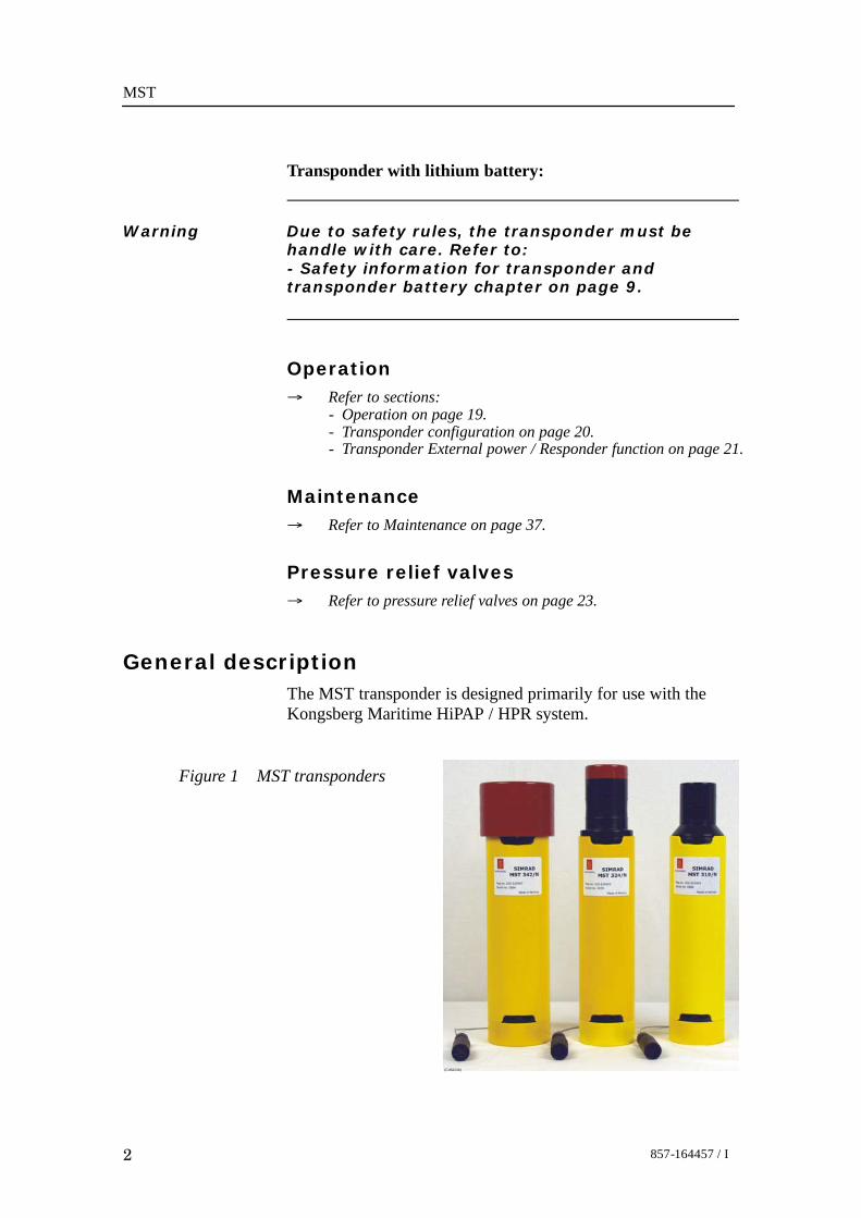
General descriptionThe MST transponder is designed primarily for use with theKongsberg Maritime HiPAP / HPR system.
Figure 1 MST transponders
(Cd6424b)

Introduction
3857-164457 / I
The MST transponder can work from its own internal batterypack, or an external power supply, and it can be interrogatedacoustically through water or via a cable (responder function).The transponder housing is an aluminium cylinder which isanodised and polyurethane coated to protect against corrosionand abrasion.The unit is designed with a modular construction. Theelectronics, battery pack, transducer and end cap can easily bereplaced individually.MST features:• External channel selection:
- 56 channels for HiPAP / HPR 400- 14 channels for HPR 300.
• Operator selectable source level to optimise battery life.• Operator selectable sensitivity.• Both transponder and responder function.• Fast battery charging (requires rechargeable battery).
Available transpondersThis manual covers the following transponders:
Transponderseries
Model Battery
MST 319MST 319/N depth 1000 m, transducer + 90_ RechargeableMST 319/L depth 1000 m, transducer + 90_ Lithium
MST 324MST 324/N depth 2000 m, transducer + 45_ RechargeableMST 324/L depth 2000 m, transducer + 45_ Lithium
MST 342MST 342/N depth 4000 m, transducer + 20_ RechargeableMST 342/L depth 4000 m, transducer + 20_ Lithium

MST
4 857-164457 / I
TransducersThere are three transducer beamwidths available:• A 180° hemispherical transducer• A 90° cone transducer• A 40° cone transducer.
Beam patternsThe figure below presents examples of beam patterns. A beampattern shows the transmit/receive sensibility in the differentdirections.
Figure 2 Examples of beam patterns
MST 319 seriesSource level = 190 dB
MST 324 series
MST 342 series
(Cd6413)
0
-30
-10 dB
30- 30
-60-20
90
60
-40
-40-30-20-10
-120
-150
180
150
120
-30
-10 dB
30- 30
-60-20
90
60
-40
-40-30-20-10-90
-120
-150
180
150
120
0
-30
-10 dB
30- 30
-60-20
90
60
-40
-40-30-20-10
-120
-150
180
150
120
AccessoriesA floating collar is available to fit around the transponder.

Introduction
5857-164457 / I
Transponder model identification principlesThe transponder name consists of the model name, the modelnumber and any options included.
The name contains three letters followed by three numbers. Theletters after the numbers describe the options (see example below).
Model nameMST = Mini SSBL Transponder
Model numberThe three digits number describe:Digit 1: frequency bandDigit 2: depth ratingDigit 3: beamwidthThe following are available:
1st number 2nd number 3rd numberFrequency band Depth rating Transducer
beamwidth
3 = 30 kHz 1 = 1000 m 2 = 20°2 = 2000 m 4 = 45°4 = 4000 m 9 = 90°
OptionsN = NiMH Rechargeable battery pack
L = Primary Lithium battery pack
Example: MST 319/NThe example given (MST 319/N) therefore indicates that thetransponder unit is a mini SSBL transponder, operating in the 30kHz band, rated to 1000 meters depth, with a90° beamwidthand a NiMH rechargeable battery.

MST
6 857-164457 / I
TECHNICAL SPECIFICATION
Common specifications
GeneralThe technical details given in this paragraph are general for allthe MST transponder types.
Housing material Anodised aluminium
Housing coating Polyurethane
Operating temperature 0°C to +30°C
Connectors
Transponder connector type Subconn MCBH5M (5 pin)Pigtail connector type Subconn MCIL5F (5 pin)
Power supplyThe following power supply options are available:• Internal battery• External 22 - 26 Vdc (40 W)
Transmitter
Power maximum 100 WFrequency 27 kHz to 32.5 kHzTransmitter pulse length 10 ms
Receiver
Receiver bandwidth (-3dB) 20 kHz to 26.5 kHz
Responder operation• Responder trigger connection:
- Via the external connector.• Responder trigger signal:
- Positive logic pulse- amplitude 5 V to 25 V- 2 ms to 6 ms duration- input impedance 10 kΩ - 30 kΩ (non resistive).

Technical specifications
7857-164457 / I
Source level and receiver sensitivity
Model Source level - max(2 steps)
24 V ext. power / battery
Receiver sensitivity(2 steps)
MST 319 190 dB*184 dB
100 dB*110 dB
MST 324 197 dB*191 dB
100 dB*110 dB
MST 342 203 dB*197 dB
100 dB*110 dB
* Factory pre-set.
MST 319Weight in air / water 2.4 kg / 1 kgOperating depth maximum 1000 mTransducer beam ±90°
→ Outline dimension, refer to page 56.
MST 324Weight in air / water 2.7 kg / 1.2 kgOperating depth maximum 2000 mTransducer beam ±45°
→ Outline dimension, refer to page 56.
MST 342Weight in air / water 4.1 kg / 2.0 kgOperating depth maximum 4000 mTransducer beam ±20°
→ Outline dimension, refer to page 56.

MST
8 857-164457 / I
Floating collars
1000 / 2000 m floating collar
Type no 119-217081Deep rating 2000 mBuoyancy with 319 TP 4.5 kgBuoyancy with 324 TP 4 kgOverall height with cage 549 mmDiameter 275 mmColour orange
→ More information, refer to page 56.
4000 m floating collar
Type no 119-217083Deep rating 4000 mBuoyancy with 342 TP 3.5 kgOverall height with cage 597 mmDiameter 290 mmColour orange
→ More information, refer to page 56.
Battery charger→ Outline dimension, refer to page 56.

Safety information
9857-164457 / I
SAFETY INFORMATION FOR TRANSPONDERAND TRANSPONDER BATTERY
IntroductionThis section includes transponder safety information for theKongsberg transponders with lithium battery and separateKongsberg transponder lithium batteries. It also includesemergency procedures.
Product identification
Product nameAll Kongsberg Maritime transponders with a lithium battery,and separate Kongsberg Maritime transponder lithium batteries.→ Refer to Kongsberg Maritime transponder instruction manuals
for the actual model.
Battery designA transponder lithium battery consists of several battery cellsthat are electrical connected, both in serial and parallel.A transponder lithium battery consists of two separate parts:• Receiver part (Rx)• Transmitter part (Tx)There are transponder batteries with different number of cells,voltages and capacity.→ Refer to Kongsberg Maritime transponder instruction manuals
for the actual model.All transponder batteries include protection againstshort-circuits (re-settable fuses) and reverse current (diodes).
Battery chemistryA transponder lithium battery consists of cells with chemistry:Lithium Thionyl Chloride - Li/SOCl2• Negative electrode: Lithium metal (Li)• Positive electrode: Thionyl chloride (SOCl2)• Electolyte: Solution of lithium tetrachloroaluminate
(LiAlCl4) in thionyl chloride

MST
10 857-164457 / I
Battery cell manufacturers/typesA transponder lithium battery consists of cells from one or twoof the following types:• Tadiran TL-2300• Sonnenschein SL-780• Saft LS 33600• Saft LSH 20• Sonnenschein SL-760
Hazards identification
GeneralShort-circuits, overheating, mechanical damage and exposure towater can start chemical reactions and high currents inside thetransponder lithium battery. This can generate noxious gasesand/or danger of explosions. The chemical reactions willcontinue without additional supply of oxygen, as the batterycells contain the necessary ingredients for maintaining thechemical reactions.During operation, the battery is placed inside the transponder.Water ingression into the transponder can cause dangeroussituations.
Danger of explosions• If the cells that form the battery reach the critical temperature
of 180_ C, they will explode.• Water ingression - The battery temperature will increase,
caused by the high internal currents. The temperature canreach the critical point of 180_ C.
• Water ingression - Electrolysis gives hydrogen. Togetherwith oxygen, hydrogen can create oxyhydrogen gas inside thetransponder (depends on the concentration). This gas is veryinflammable/explosive.
• Water ingression - Chemical reactions in the battery willcause a pressure build-up inside the transponder. Thetransponder can explode if the inside pressure is high enough.
• If the transponder explodes, either the transducer or thebottom end cap will blow out, or the transponder becomesfragmented. This can cause serious damages on personneland/or equipment.

Safety information
11857-164457 / I
• Some transponders have a relief valve that will preventover-pressure. Noxious gases will then leak out of thetransponder until the chemical reactions have stopped.
Note The relief valve can be plugged, caused by products from thechemical reactions during an emergency as described above.
Noxious gases• Thionyl chloride (SOCl2)• Sulphur dioxide (SO2)• Hydrogen chloride (HCl)• Chlorine (Cl2)Signs and symptoms:
• Corrosive fumes with pungent odour, is very irritating toskin, eyes and mucous membranes. Over-exposure can causesymptoms of non-fibrotic lung injury and membraneirritation.
Inhalation:• Lung irritant.Skin contact:
• Skin irritant.Eye contac:
• Eye irritant.Ingestion:• Tissue damage to throat and gastro/respiratory tact if
swallowed.
Medical conditions:
• Eczema, skin allergies, lung injuries, asthma and otherrespiratory disorders may occur.
MST
12 857-164457 / I
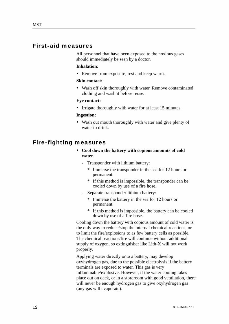
First-aid measuresAll personnel that have been exposed to the noxious gasesshould immediately be seen by a doctor.Inhalation:• Remove from exposure, rest and keep warm.Skin contact:• Wash off skin thoroughly with water. Remove contaminated
clothing and wash it before reuse.Eye contact:• Irrigate thoroughly with water for at least 15 minutes.Ingestion:• Wash out mouth thoroughly with water and give plenty of
water to drink.
Fire-fighting measures• Cool down the battery with copious amounts of cold
water.- Transponder with lithium battery:
* Immerse the transponder in the sea for 12 hours orpermanent.
* If this method is impossible, the transponder can becooled down by use of a fire hose.
- Separate transponder lithium battery:* Immerse the battery in the sea for 12 hours or
permanent.* If this method is impossible, the battery can be cooled
down by use of a fire hose.Cooling down the battery with copious amount of cold water isthe only way to reduce/stop the internal chemical reactions, orto limit the fire/explosions to as few battery cells as possible.The chemical reactions/fire will continue without additionalsupply of oxygen, so extinguisher like Lith-X will not workproperly.Applying water directly onto a battery, may developoxyhydrogen gas, due to the possible electrolysis if the batteryterminals are exposed to water. This gas is veryinflammable/explosive. However, if the water cooling takesplace out on deck, or in a storeroom with good ventilation, therewill never be enough hydrogen gas to give oxyhydrogen gas(any gas will evaporate).

Safety information
13857-164457 / I
Personals protectionFire/explosion:• Use smoke-diving equipment.Relief valve opens and noxious gasses come out:• Use self-contained full-face respiratory equipment, and
protective equipment of rubber or plastic.Opening transponder with defect/possible defect battery:• Use self-contained full-face respiratory equipment, and
protective equipment of rubber or plastic.Opening a functioning transponder:• Use protective goggles.
Handling
IntroductionAll personnel that handle transponders must know thetransponder’s status:
’Functioning’ - ’Failing’ - ’Unknown’A Transponder with unknown status, must be handled as atransponder that is failing.
Recovering a ’functioning’ transponder• All transponders recovered from the sea, should be placed in
a safe place out on deck and controlled for minimum 2 hours:- Look for outer damages that could involve a water
leakage.- The transponder housing temperature must be checked to
verify a possible temperature increase in the lithiumbattery.
Recovering a ’failing’ transponder• Handle as possible water ingression.• Evacuate all unnecessary people.• Recover the transponder with great precaution. Use a crane.• No people should be near the transponder when it is lifted up
on deck.• Place the transponder in a safe place out on deck, shielded
from people and vital equipment.

MST
14 857-164457 / I
• Fasten the transponder in a crane, ready to lower it into thesea again.
• Control the transponder for minimum 2 hours:- Look for outer damages that could involve a water
leakage.- The transponder housing temperature must be checked to
verify a possible temperature increase in the lithiumbattery.
Failing and normal temperature:• Take out the battery, see ”Opening a transponder with
defect/possible defect battery”.→ Refer to page 15.Failing and increasing temperature:• See ”Handling a heated or self-heated transponder”.→ Refer to page 14.
Handling a heated or self-heatedtransponder• Evacuate all unnecessary people.• Fasten the transponder to a rope and immerse it in the sea for
12 hours or permanent.- If this method is impossible, the transponder can be cooled
down with copious amount of cold water. Use a fire hose.• Recover the transponder and control the temperature.• Repeat this until the temperature is low and stable.• The transponder can now be opened, see “Opening a
transponder with defect/possible defect battery”.→ Refer to page 15.
Handling a transponder if the relief valveopens• Evacuate all unnecessary people.• Use necessary protection equipment.• Fasten the transponder to a rope and immerse it in the sea for
12 hours or permanent.- If this method is impossible, the transponder can be cooled
down with copious amount of cold water. Use a fire hose.• Repeat this until no gases come out the check valve and the
temperature is low and stable.

Safety information
15857-164457 / I
• The transponder can now be opened, see “Opening atransponder with defect/possible defect battery“.
→ Refer to page 15.• Wash out chemical reaction products with water.
Opening a transponder with defect/possibledefect battery• The transponder is reported failing. There could have been
water ingression in the transponder.• Open the transponder in a safe place out on deck, shielded
from people and vital equipment.• Use necessary protection equipment.
Caution Do not stand in front of transducer or bottom end cap,when opening the transponder.
• If there has been water ingression, and the battery is stillheated:- Disconnect the battery from the transponder electronics,
and then see “Handling heated or self-heated separatebattery”→ Refer to page 15.
• Wash out chemical reaction products with water.
Opening a ’functioning’ transponder• The transponder is reported functioning.• Open the transponder in a safe place out on deck, shielded
from people and vital equipment.
Caution Do not stand in front of transducer or bottom end cap,when opening the transponder.
Handling heated or self-heated separate battery• Evacuate all unnecessary people.• Fasten the battery to a rope and immerse it in the sea for 12
hours or permanent.- If this method is impossible, the battery can be cooled
down with copious amount of cold water. Use a fire hose.• Wash out chemical reaction products with water.

MST
16 857-164457 / I
Storage
Caution A transponder that is failing, must be stored in a safeplace out on deck, shielded from people and vitalequipment.
A transponders that is functioning, and separate batteries can bestored indoors.
• Storage temperature:
- Recommended storage temperature lies between 0º C and+25º C (max +50º C, min -55º C).
• Storage relative air humidity:
- Recommended relative air humidity is 40 to 70%.
• A transponder/separate battery must not be stored directly inthe sunlight.
• A battery must not be exposed to water.
• For long term storage, the battery must be disconnected fromthe transponder electronics.
• Storeroom:
- A solid room with study racks for transponders/separatebatteries.
- A room where no people are staying, or no vitalequipment is placed.
- Good ventilation.
- Clearly identified.
Caution A fire station, with fire hose (water), must be placedoutside the storeroom.
Ecological information
A lithium thionyl chloride battery does not presentenvironmental hazard.

Safety information
17857-164457 / I
Disposal considerations• A lithium thionyl chloride battery does not contain any heavy
metals, and is therefore not regarded as special waste(contains only biodegradable parts).
• A used transponder lithium battery often contains asignificant amount of residual energy. It is the danger ofexplosion that presents a problem when disposing a battery.- Used batteries must therefore be handled with the same
care as new ones.
Caution For safe disposal, contact a company that has beenapproved to collect and dispose lithium batteries.

MST
18 857-164457 / I
Transport informationAll transponders with a lithium battery and separate transponderlithium batteries must be shipped in accordance with theprevailing regulations:Transponder with lithium battery:UN no. 3091, Class 9 Miscellaneous(Lithium batteries contained in equipment)Separate transponder lithium battery:UN no. 3090, Class 9 Miscellaneous (Lithium batteries)Transport:
Aircraft: IATA DGRSea Transport: IMDG CodeRailway: RIDRoad transport: ADR
• Aircraft - Only new transponder lithium batteries can betransported by air.
• Aircraft - Transport of all transponders with new lithiumbattery and new separate transponder lithium batteries by airis only permitted onboard cargo aircraft. The goods must beclearly labelled:CARGO AIRCRAFT ONLY
Caution Transponder with lithium battery - During transport thelithium battery must always be disconnected from theelectronics.
• Original transponder/battery cages must be used.

Operation
19857-164457 / I
OPERATION
GeneralThe transponder is designed for operation in water only.However, the transponder may be operated in air for testpurposes over a short period of time.
Activate the transponder1 Switch the unit ON.
When used as a transponder:- This is done by inserting the on / off plug into the end
cap connector.When used as a responder / connected to external power:- If external power supply / responder trig are to be used:
→ Refer to page 21 for for details.
Figure 3 MST transponder base with on/off plug
On/off plug
Transponder base(Cd6416a)
- The unit will ping twice to indicate that it is activated.If:
- The unit does not ping, switch the unit OFF and leaveit for approximately 5 minutes. Switch the unit backON and listen for the pings.
- The unit emits a triple ping, this indicates the channelswitches are set to an illegal channel (for example 30).The triple ping will be emitted every 10 seconds until alegal channel is set.

MST
20 857-164457 / I
Note The triple ping will also be emitted if a switch is slightly off itsposition.
2 Check that the unit replies in air as follows:- For HiPAP / HPR 400 channels - use the HiPAP / HPR
400 and the test transducer.- For HPR 300 channels - use the TTS 286 Transponder
Test Set.- Alternatively, lower the unit into the water alongside
the ship, and test with the topside system.
Deactivate the transponder/responder
Note The MST must always be switched off when not in use.
1 Switch the unit OFF.When used as a transponder:
- This is done by disconnecting the on / off plug.When used as a responder / connected to external power:
- This is done by disconnect the power / responder cable.
Changing the transponder channel
PrinciplesChannel selection is done via the two switches on the end cap.→ Refer to the figure on page 47.Before you deploy the transponder, the required channel must beselected.
Caution The channel switches must be set accurately - if not,the MST will not operate correctly.
1 Switch OFF the MST.2 Set the channel switches to the required channel.→ Refer to figure on page 47.

Operation
21857-164457 / I
3 Wait 5 minutes to ensure the MST has re-set correctly.4 Switch ON the MST.5 Listen for two (2) transmission pulses.6 If no transmission pulses are heard, repeat steps 1 to 5.
Caution If three (3) pulses are transmitted and repeated every10 seconds, an illegal channel has been selected.
External power supply and / or responder trigIf the external power supply and / or responder trig are to beused, carry out the following additional checks:1 Check the external power / responder cable.
- Connect wire 2 and 5 in the pigtail(the ON / OFF function).
Figure 4 Pigtail wire connection
(Cd6
558)
14253
Ext. TrigExt. PowerGnd
On/Off
Pigtailconnector
2 Ensure that the external supply is between 22 and 26 Vdc.
Note The voltage supplied must not be below 22 Vdc. If below, theMST will take its power from the internal battery.
3 Check the responder trigger signal. The signal values are:- Positive logic pulse- Amplitude 5 V to 25 V- 2 ms to 6 ms duration.
4 Set the channel switches to the required channel.5 Switch ON the MST by inserting the external
power/responder cable.→ Refer to page 19 for for details.6 If the responder function is to be used, the unit must be
checked in air on deck, using the topside system.

MST
22 857-164457 / I
Pre-deployment checksPrior to deployment of the transponder, it is important that thefollowing checks are made to ensure correct operation.1 Ensure that both retaining cords are in place.→ Refer to figure on page 38.2 If the unit has been altered from the factory pre-sets,
check that the unit is configured according to yourrequirements.
→ Refer to Source level / Sensitivity settings, on page 36.3 if the unit has a rechargeable battery, ensure the unit has
been recently charged.→ Refer to page 27 for for details.4 Ensure that the pressure relief valves (channel switches)
are in closed position.→ Refer to page 23.5 Select the channel required via the end cap switches.→ Refer to page 20 for for details.6 Switch the unit ON.→ Refer to page 19 for for details.
DeploymentWhen you fit the transponder onto a vehicle / structure, the unitmust be positioned with the transducer upright and there mustbe a clear line of sight between the transponder’s head and theship’s transducer. To secure the transponder, use a hose clampwith rubber protection.
Recovery checks1 After recovery, switch the unit OFF.2 Wash the unit thoroughly in warm fresh water to dissolve
any salt deposits and clean off any sand or silt.3 As an extra precaution, it is recommended that the unit is
left to soak in fresh water to allow salt to dissolve anddiffuse from hard-to-reach areas, such as crevices aroundO-rings, and between mating parts.- Leave the unit to soak for 24 hours, or as long as
practical conditions allow.If a rechargeable unit is to be re-deployed imminently, put theunit on charge.

Operation
23857-164457 / I
Pressure relief valvesThe two channel selector switches, have dual O-rings, and theywork as follows:• One will seal only when the switch is pressed fully into its
seat.• The other one will seal, even with the switch pushed approx.
2 mm outwards.- If one or both switches rest in a not fully home position,
or they feel springy when pushed in place, it means thereis some degree of overpressure inside the MST.
→ Refer to page 27.If the pressure becomes too big, one or both valves will vent.When the pressure has been relieved, both the switches can bepushed back into position.
Operation of pressure relief valves
Manual ventingInsert the dedicated tool (or any standard M3 screw) into thecentre of both channel selector switches, and pull out (approx. 5mm) until it feels loose and an O-ring is just visible. (See figurebelow.)This operation will immediately release any overpressure insidethe MST, and it will also ensure that the O-rings and valve ismoving freely.
Figure 5 Manual venting
(Cd6
571)
Trip point for pressure releaseGently let the spring pull the selector switch back. The switchwill now rest approx. 3 mm above the surface of the end cap. Inthis position the valve is at the trip point to venting, and will doso without resistance. This position is ideal during charging.

MST
24 857-164457 / I
Closing the valve
Simply push the switch until it is flush with the end cap.
Floating collar
GeneralA floating collar consists of two halves. These halves are placedaround the transponder housing and bolted together. The collaris equipped with cages to protect the transducer and end cap.Reflective bands are placed on all sides and bottom, to aidvisual location in dark conditions.
Floating collar for MST 319 / MST 324
(Cd6
906)
Figure 6 MST 324 with floating collar

Operation
25857-164457 / I
Floating collar for MST 342The MST 342 floating collar has a support ring for extratransponder support. The support ring consists of two halfs andmust be mounted on the transponder, before the floating collar isbolted together. This is illustrated in the figure below.
Figure 7 MST 342 with support ring,placed in the floating collar
(Cd6
907)
Support ring
Figure 8 MST 342 with floating collar
(Cd6
908)

MST
26 857-164457 / I
BATTERIESA MST transponder is delivered with the following types ofbatteries:
• NiMH rechargeable battery.
• Lithium battery (not rechargeable).
Battery lifetime
Note Always allow a safety margin of error in any operationcalculations.
NiMH
Max source levelRechargeable battery pack
(fully charged)
Quiescent 1 ping per sec
MST 319 480 hours 18 hours/64.800 no. of replies
MST 324 480 hours 18 hours/64.800 no. of repliess
MST 342 480 hours 9 hours/32.400 no. of replies
Lithium
Max source levelLithium battery pack
(fully charged)
Quiescent 1 ping per sec
MST 319 960 hours 36 hours/129.600 no. of replies
MST 324 960 hours 36 hours/129.600 no. of repliess
MST 342 960 hours 18 hours/64.800 no. of replies

Battery
27857-164457 / I
Battery charger• Charge method: Constant current.• Charge rate: 0,5 C (Fast charge).• Permit fast charge between 10_C and 40_C.• Detection of fully charged battery: Temperature rise (dT/dt),
maximum temperature, maximum time (180 min).• Trickle charge by pulse current.
Charging the batteryThe battery is charged inside the MST. This is connected withsome risk, so please follow the charge procedure carefully.
Warning When you are charging the battery ensure:- Good ventilation and stable temperature.- The transponder is not covered.- No open fire, sparks or smoking in the area.
SafetySafety has been a main criteria when designing the battery, thecharger, the transponder electronics and the housing.• Battery→ Refer to safety information section on page 9.• Charger (see section Battery charger above)• Transponder electronics:
- Includes battery undervoltage control that disconnects thebattery from the electronics when the battery voltage is tolow. Reduces the possibility of reverse polarity.
• Transponder housing:- The channel selector switches also act as safety pressure
relief valves.→ Refer to page 23.
Note If the inside pressure becomes too high, the valves will vent. Thiscan be caused by several factors.- High ambient temperature.- Heat generated during charging.- Batteries may leak some hydrogen gas and/or oxygen whencharging.

MST
28 857-164457 / I
Charge procedure1 Switch OFF the transponder.2 Acclimatise the transponder.
- The battery must have a temperature between 10_C and40_C. Recommended charge temperature is 25_C.
3 Manually vent the two pressure relief valves.→ Refer to pressure relief valves on page 23.4 Connect the charger plug to the MST.5 Connect Power supply to mains (110 Vac or 220 Vac). The
Green light on the charger will illuminate.6 The charging will start:
Stage 1 - Charger measures the battery status:Charger Status LED - flashing red light- The charger checks that the battery temperature is
between 10_C and 40 _C and that the battery voltage isbetween 15 V and 25 V.
- The charger will trickle charge the battery during thismode. The charger will stay in this mode until thebattery satisfies the temperature and voltagerequirements.
Stage 2 - Fast chargeCharger Status LED - constant red light- Fast charge, constant current. The charger will measure
temperature, voltage and time during this mode.- If the battery voltage exceed the maximum limit
(25 V), the charger will stop fast charge until thebattery voltage is within the voltage requirements(15 V - 25 V). During this mode the charger will tricklecharge the battery.The Battery Status LED will turn OFF.
Stage 3 - Detection of fully charged batteryMethods for detection of fully charged battery:- Temperature rise (dT/dt)- maximum temperature- maximum time.When one of these criteria occur the charger will stop thefast charge mode.Stage 4 - Completely charged battery and trickle chargeCharge Status LED - constant green lightWhen the battery is fully charged, the charger will starttrickle charge mode.The transponder is now ready for operation!

Battery
29857-164457 / I
Note It is not recommended that the battery is trickle charged for along time. It is better to start fast charge again to top the batteryjust before operation.
7 Disconnect Power supply from the mains(110 Vac or 220 Vac).
8 Disconnect charger plug from the MST transponder(external connector).
9 Ensure that the pressure relief valves (channel switches)are in closed position.
→ Refer to page 23.
Figure 9 Battery charger
Charger status LED
Transponder base220 V / 110 V
(Cd6414a)

MST
30 857-164457 / I
Replacement of the battery packThe battery is build into the chassis. To replace it, follow theprocedure below:1 Open the transponder.→ Refer to page 37 for details.
2 Disconnect the battery connector.→ For connector location - refer to the figure on page 40.
3 Remove the battery.4 Assembly is the reverse of dismantling.
Battery storageIf the unit is not to be re-deployed in the near future, store it in asuitable environment.The recommended temperature range for long-term storage ofthe rechargeable battery cells is -20°C to +35°C*. Storedcapacity decreases over time due to the self-discharge of therechargeable battery cells.Self-discharge is dependent on temperature. The higher thetemperature the greater the self-discharge over time. Long-termstorage has no permanent effect on capacity. Loss in capacitydue to self-discharge are reversible.
*The relative humidity should be < 50%.
Transponder configuration
31857-164457 / I
CONFIGURATION
HPR 400 channels
Note The following channel numbers are not allowed:- “Twin-figured” B(11, 22, 33 ...99)- B(01, 02, 03 ...09)Refer to table 1, HPR 400 channel numbers and operationfrequencies.
The HiPAP / HPR 400 system interrogates the transponders bytransmitting two pulses with frequencies according to theprotocol. The transponder reply is determined by the secondinterrogation pulse.
Note A HiPAP system uses the same channel working principle as aHPR 400 system. The following paragraphs, therefore describeonly the principles for an HPR 400 system.
A total of 56 positioning frequency channels are available. Referto table 1 for frequencies.
When the first interrogation pulse is an odd number, the reply is250 Hz higher than it is when the pulse is an even number.
• Switch A is set to the first digit of the desired channelnumber - Rx1.
• Switch B is set to the second digit of the desired channelnumber - Rx2.
→ Refer to the timing diagram on page 32.
• Example:If channel B12 is to be selected, switch A must be set toposition 1 and B to position 2. Referring to table 1, the firsttransmission frequency will then be 21,000 Hz and thesecond transmission frequency will be 21,500 Hz.To find the reply frequency: The second frequency number is2 so go to rows Be2/Bo2, and the first frequency number isodd (1) therefore the Bo2 row is used. The reply frequency istherefore 29,250 Hz.

MST
32 857-164457 / I
HPR 300 channelsThe HPR 300 system interrogates the transponders bytransmitting one pulse with frequency according to the protocol.For the HPR 300 a total of 14 channel numbers (frequencycombinations) are available.Refer to table 2 for frequencies, and set switch A and switch Bto the required interrogation frequency to achieve the desiredtransponder beacon transmission frequency.
Turn-around = 60ms
Turn-around = 30ms
Rx1
Rx1 Rx2 Tx
Tx
20 ms
20 ms 20 ms
10 ms 10 ms
10 ms 10 ms 10 ms
HPR 400 (SSBL)
HPR 300 (SSBL)
(CD3805)
Figure 10 Transponder reception andtransmission signal timing diagram

Transponder configuration
33857-164457 / I
HPR 400 channels and positioningfrequencies tableTransponderchannel
Operating frequencieschannelnumber Interrogation Replay
Be1Bo1Be2Bo2Be3Bo3Be4Bo4Be5Bo5Be6Bo6Be7Bo7Be8Bo8
21000210002150021500220002200022500225002300023000235002350024000240002450024500
28500287502900029250295002975030000302503050030750270002725027500277502800028250
Table 1 HPR 400 channel numbers and operating frequenciesWhere:B = Frequency band (30 KHz)e = Even numbers (2, 4, 6, 8)o = Odd numbers (1, 3, 5, 7)
HPR 300 channels and positioningfrequencies table
SwitchA
SwitchB
Transponderchannel
Operating frequenciesA
settingB
settingchannelnumber Interrogation Reply
00000000012345
12345678912345
1234567891122334455
2049221552221242272723364240382451025000260422155222727239232512626455
2976230488312503184732468271732777728409290702717328409297623125032468
Table 2 HPR 300 switch settings, channel numbers andoperating frequencies

MST
34 857-164457 / I
FunctionsThe Transponder includes the following functions:
• Transponder• Responder• External powerThe Transponder function is default. To activate the responderor the external power functions, external connection is required.
Transponder functionThe transponder function enables the unit to respond to ahydroacoustic interrogation signal from a compatible surface /underwater unit. The transponder function requires:1 An allowable transponder channels must be selected.2 The unit must be switched on.
- Once selected, the transponder will reply only to thecorresponding interrogation channel.
• If no valid interrogations are received after 65 seconds, thetransponder unit will enter ‘sleep’ state whereby the drain onthe battery pack will be at a minimum.
• On receipt of a valid interrogation the unit will ‘wake up’and reply to subsequent interrogations. The topside unitdecodes the reply to give just the range, or the range andbearing, dependent on the type of surface unit used.
Responder functionThe responder function enables the unit to reply to a “Trigger”pulse via the external connector on the end cap.→ See also page 21.Proceed as follows:1 Select the desired channel.2 Switched ON the MST.
- This is done by inserting the external power / respondercable.
3 Give a valid trigger pulse from the topside system, and thetransponder will reply at the previously selected channel.
• If the responder trigger signal is lost, the transponder willautomatically revert to the transponder function after 65seconds. The responder function is automatically initiated bythe presence of a valid “Trigger” pulse.

Transponder configuration
35857-164457 / I
External power functionWhen the transponder is set to the external power function, itrequires a dc supply of between 22 Vdc and 26 Vdc.→ See also page 21.
Proceed in the following order:1 Select the desired channel.2 Switched ON the MST.
- This is done by inserting the external power / respondercable.
• The transponder will be powered from the external supply aslong as the external supply voltage remains above 22 V. If theexternal voltage falls below this level, or is lost (for exampleumbilical failure), the transponder will automatically revertto its internal battery pack (transponder function).

MST
36 857-164457 / I
Source level (Tx power) andsensitivity (Rx gain) adjustment
GeneralFor certain applications, you may need to adjust the source level(Tx power) and sensitivity (Rx gain) settings. This is done onthe main board.
Note If these are adjusted from their factory pre-sets, make a note toensure units are not deployed with the wrong configuration at alater date.
To reduce the factory pre-set Tx powerWhen working at short ranges in a quiet acoustic environment,you may require to reduce the factory pre-set source level.Reduced source level will increase battery life.To reduce the factory pre-set source level:1 Open the transponder.→ Refer to page 37 for details.2 Locate the main board.3 Move the jumper to the required position.→ Refer to the figures on page 45.4 Close the transponder.→ Refer to page 41 for details.
To reduce the factory pre-set Rx gainThis can be performed when working at short ranges wherethere is a high degree of low frequency acoustic or electricalnoise at the transponder. To reduce these problems, you mayreduce the factory pre-set sensitivity setting as follows:1 Open the transponder.→ Refer to page 37 for details.2 Locate the main board.3 Move the jumper to the required position.→ Refer to the figures on page 45.4 Close the transponder.→ Refer to page 41 for details.

Maintenance
37857-164457 / I
MAINTENANCE
GeneralThe following maintenance is normally required:• Charging the battery (if rechargeable battery is used).• Lubrication of the external connector - refer to page 42 for
more information.• Washing the unit.To select the source level and sensitivity, and to change thebattery pack, the unit must be opened.
Caution Electronic devices can be destroyed by static electricity.It is therefore essential that full protection againststatic is practised by service engineers.Although the unit is resistant to mechanical vibrationand shock, every effort must be made to avoid carelesshandling when the unit is in use or being transported.
O-ringsWhenever the transponder is opened and the O-rings areexposed, precautions must be taken. This includes keeping theO-rings and mating surfaces free of dust and debris. If any ofthe mentioned surfaces is to be cleaned, it is important to uselint-free objects. Q-tips must never be used to clean areasanywhere near an o-ring.When inserting an O-ring, make sure the surface is clean, andthat it is covered with a thin film of silicone grease.
Dismantling the transponder→ Transponder assembly refer to the figure on page 50.To dismantle the transponder unit, follow the procedure below:Before you open the unit:1 Switch OFF the unit.2 Before opening the unit;
- Wash the unit thoroughly in fresh water, and dry off anymoisture on the outside.
- Any work must be carried out in a clean, dry area.- Ensure full anti-static precautions have been taken.
MST
38 857-164457 / I
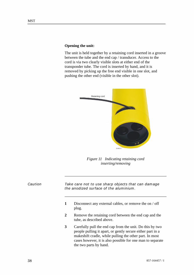
Opening the unit:
The unit is held together by a retaining cord inserted in a groovebetween the tube and the end cap / transducer. Access to thecord is via two clearly visible slots at either end of thetransponder tube. The cord is inserted by hand, and it isremoved by picking up the free end visible in one slot, andpushing the other end (visible in the other slot).
Retaining cord
(Cd6417)
Figure 11 Indicating retaining cordinserting/removing
Caution Take care not to use sharp objects that can damagethe anodized surface of the aluminium.
1 Disconnect any external cables, or remove the on / offplug.
2 Remove the retaining cord between the end cap and thetube, as described above.
3 Carefully pull the end cap from the unit. Do this by twopeople pulling it apart, or gently secure either part in amakeshift cradle, while pulling the other part. In mostcases however, it is also possible for one man to separatethe two parts by hand.

Maintenance
39857-164457 / I
Caution Observe the 5 mm orientation peg at either end of thetube. When pulling apart, make sure to keep thisorientation until parts are completely free from eachother. Forceful twisting of the parts relative to eachother while the internal parts are still mated, willdamage the unit.
4 Remove the retaining cord between the transducer and thetube, as described above.
5 Pull the tube from the transducer.- All internal parts are now clearly visible and accessible.
Replacement of the transducerThe transducer is a sealed unit and can not be opened. If it is notworking, the whole unit must be replaced. To replace thetransducer, follow the procedure below:1 Open the transponder.→ Refer to page 37 for details.
2 Remove the soldering at the connections TD+ and TD-.→ The wires location, see the figure on page 50.
3 You can now remove the transducer.4 Assembly is the reverse of disassembly.

MST
40 857-164457 / I
Replacement of the main boardTo replace the main board, follow the procedure below:1 Open the transponder.→ Refer to page 37 for details.
2 Disconnect the battery pack and the transducer.→ Refer to the figure on page 50.
3 De-solder the obvious wires from the solder posts on theboard. Ensure adequate labelling for reassembling.
4 Unscrew the six fixing screws (see figure below).5 You can now remove the main board.6 Assembly is the reverse of disassembly.
Caution If you force the end cap into the housing, the edgeconnector may be destroyed.
Figure 12 Position of the main board fixing screws
Main board fixing screws (6)
Battery clamp rod
(Cd6
434)

Maintenance
41857-164457 / I
Replacement of the interface boardTo replace the interface board, follow the procedure below:1 Open the transponder.→ Refer to page 37 for details.2 Unscrew the screws holding the interface board
(see figure below).3 De-solder the obvious wires from the solder-posts on the
board. Ensure adequate labelling for reassembling.4 You can now remove the interface board.5 Assembly is the reverse of disassembly.
Figure 13 Position of the interface board fixing screws
Interface board fixing screws (3)
Battery clamp rods (2)
(Cd6
459)
Replacement of the battery pack→ Refer to page 30.
Transponder assemblyAssembly is the reverse of disassembly, but note the following:
Note The condition of the O-rings must be checked. If there is anydoubt as to their condition, or if they have been in use for morethan 1 year, they should be replaced.
Caution Ignoring these recommendations may result in floodingof the MST unit.
Note Backup rings are used on all seals on all MST 324transponders.

MST
42 857-164457 / I
Procedure for handling the O-rings:1 Check the condition of the rings and carry out any
necessary replacements.2 Ensure the O-ring surfaces are clean and free from any
dust, debris or old grease.3 Lightly grease the rings prior to assembly using Molykote
33 grease or similar.4 Re-fit the O-rings (see figure below).
Transducer
2 ringsO- 2 ringsO-
End cap
Retaining cord
(Cd6418)
Figure 14 O-rings and retaining cord
5 Check that the ring is fitted correctly as follows:a Carefully slide the transducer assembly into the
housing till the housing meets the first O-ring.b Press the transducer fully into the housing.
Transducer handlingAt transportation and storage, the transducer face and the O-ringgrooves must be protected. Do not leave the transducer restingon the face, because even a small roughness on the support maycause a permanent distortion in the polyurethane face.As a precaution at storage, short-circuit the electrical wires. Thisprevents potential voltage build-up, which otherwise mayappear from temperature variations.
Lubrication of the external connectorThe external connector must be lubricated. The recommendedlubricant is:• Molykote 44 Medium.
Note Use it sparingly, half a match-head dose per contact isadequate.

Transponder main parts
43857-164457 / I
MAIN PARTS
OverviewA MST transponder unit consists of the following main parts:• Circuit boards• Battery pack• Transducer• End cap• Housing→ Refer to figure on page 50.

MST
44 857-164457 / I
Circuit boards
OverviewThe MST transponder electronics includes two circuit boards:• Main board• Interface boardThe transponder schematic and interconnections:
Figure 15 MST transponder schematic
01
2 3
45
6
78
90
1
2 3
45
678
9
Externalconnector
Ext .trigger
Charger powerExt. power
On/Off
GroundTP 1
TP 2
TP 3
TP 4
TP 5
1
2
3
4
5
Channelselectionswitch
Channelselectionswitch
Interfaceboard
1
2
3
4
5
6
7
8
9
10
11
12
13
14
15
16
1
2
3
4
5
6
7
8
9
10
11
12
13
14
15
16
Main board
TD +
TD -
4
3
1
Battery +
Battery sensor
Battery - Battery
TD: - 180- 90- 40
(CD6548)
16
Main boardThe main board is mounted on the chassis, and it is controlledby the processor (Philips P87C552).
Note Some components may vary, depending on the transpondermodel.
• Both the receiver and the transmitter are integrated in themain board.

Transponder main parts
45857-164457 / I
Figure 16 Jumper configuration on the main board
Tx power:Max AHigh B
B
Rx gain: A
Low BHigh
AB
ST6: LINK POS A
ST6
ST11
ST11: LINK POS A
TOP SIDE SEEN FROM COMP.SIDE 381-205332
U6 U7
U5
L3 L2
T1
TD-
L1
381- 215332
TD+
(CD
6560
a)
Interface boardThe interface board is mounted on the end cap. This boardcontains:• all the input and output interfaces for the transponder• the battery charger.
Note Some components may vary, depending on the transpondermodel.

MST
46 857-164457 / I
BatteryBattery information:→ Refer to page 26.
The battery pack is connected directly to the main board.→ Refer to the figure on page 44.
Transducers
OverviewAs a standard, two O-rings for water sealing between thetransducer and the housing are provided.The transducer is connected directly to the main board.→ Refer to page 50.
Transducer 180The transducer has a beam pattern covering one hemisphere.The two wires for electrical connection, emerge from thebottom.
Transducer 90The transducer has a 90 degrees conical beam. The transducer isoil-filled to withstand the high pressure. The two wires forelectrical connection emerge from the bottom.
Transducer 40The transducer has a 40 degrees conical beam. The transducer isoil-filled to withstand the high pressure. The two wires forelectrical connection emerge from the bottom.

Transponder main parts
47857-164457 / I
End capThe end cap holds the following:→ Refer to figure on page 19.
• ON / OFF plug (strapped onto the end cap)
• Switches for channel selection / Pressure relief valves
• External connector
Figure 17 End cap
Channel selectionswitch ‘A’
Channel selectionswitch ‘B’
External connector
(Cd6408b)
ON / OFF plug
The attached plug will act as ON switch when inserted into theexternal connector.→ See the figure on page 19.
Pressure relief valvesThe two channel selector switches, also have an additionalfunction. They are both spring loaded, to act as safety pressurerelief valves.→ How it works - see page 47.
Figure 18 External connector -internal

MST
48 857-164457 / I
External connectorThe transponder external connector is recessed within thetransponder end cap.
(Cd6408d)
12 5
3 4End cap
External connector
Figure 19 External connector
Function If an equivalent connector isused, wires may be numberedas below
External trigger/ charger LED 1 1
Ground 2
Charger power 3
External power/charger LED 2 4
On /Off 5
Table 3 Transponder external connector pin-out diagram
Housing→ Refer to technical specifications on page 6.

Spare parts
49857-164457 / I
SPARE PARTS
IntroductionThis chapter lists the parts and modules defined by KongsbergMaritime as Line Replaceable Units (LRUs) for the MSTtransponder series. These LRUs are the individual parts anditems which the manufacturers considered are replaceable by thelocal maintenance engineer. Exploded figures are included toassist you with part identification.The required mounting components (such as nuts, bolts etc.) arenot identified on the figures, and the order numbers are notallocated, as we regard these items as standard commercial partsavailable from retail outlets around the world.
Codes usedThe following codes are used in the parts lists:Part no. - Kongsberg Maritime’s part number.Item name - The name of the item.Technical data - Technical specifications and any other relevantinformation.Drw. ref. - Reference number of the production or illustrationdrawing where the item is included. If a number is given here,the drawing will be included in the manual’s/document’sdrawing file.
Drw. pos. - The item’s position number on the drawingreferenced above.No. in sys. - The quantity of the item used in the system. Notethat this information is not provided for standard componentssuch as nuts, bolts and washers.Rec. spares - The quantity of the item recommended to becarried as spares onboard the vessel. Note that this informationis not provided for standard components such as nuts, bolts andwashers.

MST
50 857-164457 / I
MST transponder - exploded viewThis paragraph displays an exploded view of a MSTtransponder. The parts lists are presented on the followingpages.
Figure 20 MST transponder - exploded view
(Cd6
408/
2154
54)
TD-TD+

Spare parts
51857-164457 / I
Common parts
General
Part no. Item name Drw. ref. No. in sys.
-- Technical data Drw. pos. Rec. spares
382--215340 Interface board (1) Figure page 50 1
-- -- N/A --
540--085075 O--rings Figure page 50 4
-- 58.42 x 2.62 7 4
599--215481 Retaining cord Figure page 50 2
-- -- 6 1
599--216333 ON / OFF plug Figure page 50 1
-- -- 8 1
370--097274 Dummy plug for transportation N/A 1
-- UV--plug MCDC5F 5p -- 1
Responder pigtail
Part no. Item name Drw. ref. No. in sys.
-- Technical data Drw. pos. Rec. spares
599--219046 MST responder pigtail -- --
-- Connector type: Subcom MCIL5F (5 pin) -- --
Charger
Part no. Item name Drw. ref. No. in sys.
-- Technical data Drw. pos. Rec. spares
LAD--219045 MST Charger adapter -- --
-- The power supply and the charger adapter plugare included (1)
-- --
1 Charger adapter plug, part. no: 380-216343Power supply, part. no: 290-098059
Batteries
Part no. Item name Drw. ref. No. in sys.
-- Technical data Drw. pos. Rec. spares
499--219504 Lithium battery pack Figure page 50 --
-- Primary (not rechargeable) 2 --
499 --215473 Chassis w/rechargable battery MST Figure pag e 50 - --
-- -- 2 --

MST
52 857-164457 /I
Floating collar
Part no. Item name Drw. ref. No. in sys.
-- Technical data Drw. pos. Rec. spares
119--217081 MST 319 / MST 324 floating collar -- --
-- -- -- --
119--217083 MST 342 floating collar -- --
-- -- -- --

Spare parts
53857-164457 / I
MST 319/N transponderPart no. Item name Drw. ref. No. in sys.
-- Technical data Drw. pos. Rec. spares
102--215453 MST 319/N Transponder unit -- --
-- -- N/A --
Main modules
Part no. Item name Drw. ref. No. in sys.
-- Technical data Drw. pos. Rec. spares
312--215523 Transducer Figure page 50 1
-- -- 4 --
382--215415 Main board Figure page 50 1
-- -- 3 --
499--215461 End cap Figure page 50 1
-- Interface board is included (1)part no, see page 51
1 --
599--215459 Housing Figure page 50 1
-- -- 5 --
→ Common spare parts and battery, refer to page 51
MST 319/L transponderPart no. Item name Drw. ref. No. in sys.
-- Technical data Drw. pos. Rec. spares
102--219655 MST 319/L Transponder unit -- --
-- -- N/A --
Main modules
Part no. Item name Drw. ref. No. in sys.
-- Technical data Drw. pos. Rec. spares
312--215523 Transducer Figure page 50 1
-- -- 4 --
382--215415 Main board Figure page 50 1
-- -- 3 --
499--215461 End cap Figure page 50 1
-- Interface board is included (1)part no, see page 51
1 --
599--215459 Housing Figure page 50 1
-- -- 5 --
→ Common spare parts and battery, refer to page 51.
MST
54 857-164457 /I
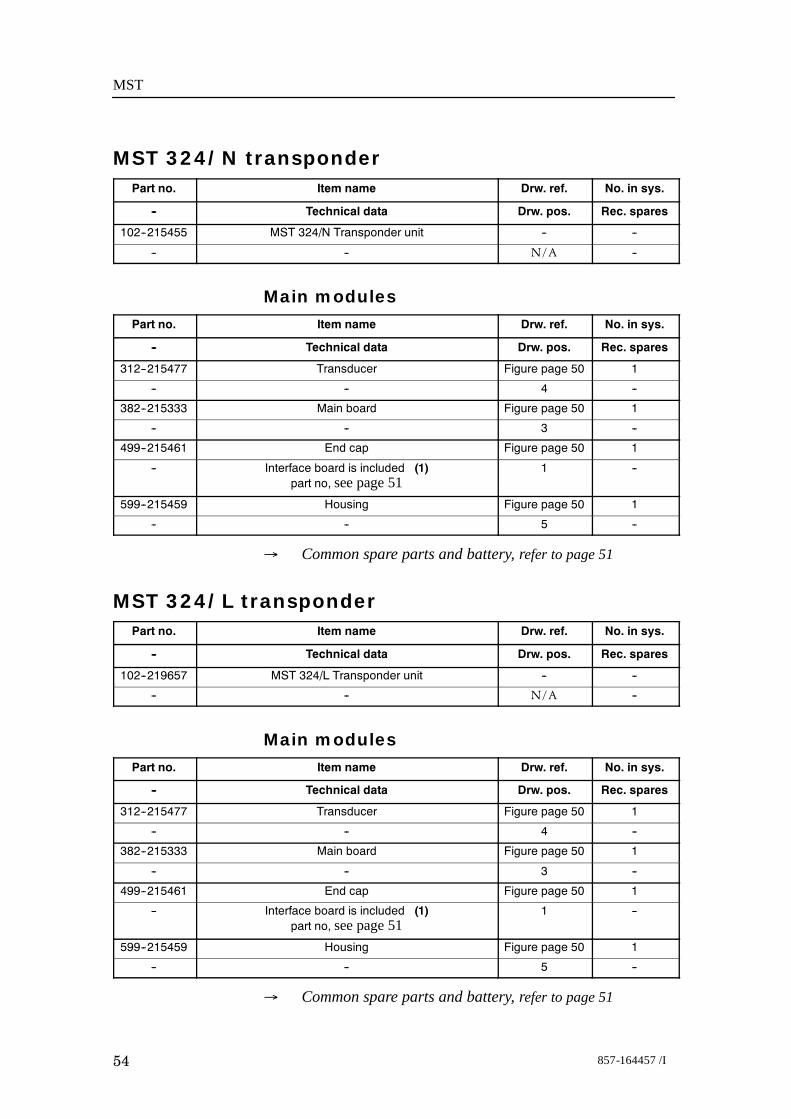
MST 324/N transponderPart no. Item name Drw. ref. No. in sys.
-- Technical data Drw. pos. Rec. spares
102--215455 MST 324/N Transponder unit -- --
-- -- N/A --
Main modulesPart no. Item name Drw. ref. No. in sys.
-- Technical data Drw. pos. Rec. spares
312--215477 Transducer Figure page 50 1
-- -- 4 --
382--215333 Main board Figure page 50 1
-- -- 3 --
499--215461 End cap Figure page 50 1
-- Interface board is included (1)part no, see page 51
1 --
599--215459 Housing Figure page 50 1
-- -- 5 --
→ Common spare parts and battery, refer to page 51
MST 324/L transponderPart no. Item name Drw. ref. No. in sys.
-- Technical data Drw. pos. Rec. spares
102--219657 MST 324/L Transponder unit -- --
-- -- N/A --
Main modulesPart no. Item name Drw. ref. No. in sys.
-- Technical data Drw. pos. Rec. spares
312--215477 Transducer Figure page 50 1
-- -- 4 --
382--215333 Main board Figure page 50 1
-- -- 3 --
499--215461 End cap Figure page 50 1
-- Interface board is included (1)part no, see page 51
1 --
599--215459 Housing Figure page 50 1
-- -- 5 --
→ Common spare parts and battery, refer to page 51

Spare parts
55857-164457 / I
MST 342/N transponderPart no. Item name Drw. ref. No. in sys.
-- Technical data Drw. pos. Rec. spares
102--215457 MST 342/N Transponder unit -- --
-- -- N/A --
Main modules
Part no. Item name Drw. ref. No. in sys.
-- Technical data Drw. pos. Rec. spares
312--215505 Transducer Figure page 50 1
-- -- 4 --
382--216262 Main board Figure page 50 1
-- -- 3 --
499--216010 End cap Figure page 50 1
-- Interface board is included (1)part no, see page 51
1 --
599--215531 Housing Figure page 50 1
-- -- 5 --
→ Common spare parts and battery, refer to page 51
MST 342/L transponderPart no. Item name Drw. ref. No. in sys.
-- Technical data Drw. pos. Rec. spares
102--219659 MST 342/L Transponder unit -- --
-- -- N/A --
Main modules
Part no. Item name Drw. ref. No. in sys.
-- Technical data Drw. pos. Rec. spares
312--215505 Transducer Figure page 50 1
-- -- 4 --
382--216262 Main board Figure page 50 1
-- -- 3 --
499--216010 End cap Figure page 50 1
-- Interface board is included (1)part no, see page 51
1 --
599--215531 Housing Figure page 50 1
-- -- 5 --
→ Common spare parts and battery, refer to page 51

MST
56 857-164457 / I
DRAWING FILE
OverviewThis section contains outline dimensions drawings. Theillustrations are based on the original system drawings.• All measurements are in mm.• The illustrations are not in scale.
• The original drawings are available in electronic format uponrequest.
DrawingsThe following are implemented:• MST 319 transponder, page 57.
• MST 324 transponder, page 58.• MST 342 transponder, page 59.
• MST 319 and MST 324 transponder with floating collar,page 60.
• MST 342 transponder with floating collar, page 61.
• MST battery charger, page 62.

Drawing file
57857-164457 / I
860-215454Rev.A
Page 1 of 1(CD30059) MST 319 transponder - outline dimensions

MST
58 857-164457 / I
860-215456Rev.A
Page 1 of 1(CD30057) MST 324 transponder - outline dimensions

Drawing file
59857-164457 / I
860-215458Rev.A
Page 1 of 1(CD30058) MST 342 transponder - outline dimensions

MST
60 857-164457 / I
830-217367Rev.A
Page 1 of 1(Cd30125)
Outline dimensions - MST 319 and MST 324 w/ floating collar

Drawing file
61857-164457 / I
N/Aprelim
Page 1 of 1(CD31006) Outline dimensions - MST 342 w/floating collar

MST
62 857-164457 / I
830-221265Rev.A
Page 1 of 1(Cd30126) Otline dimensions - MST charger

Index
63857-164457 / I
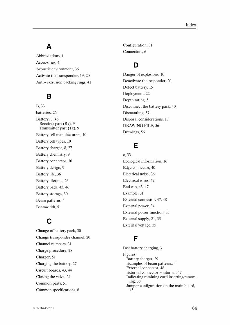
INDEXThe next pages presents the index of this manual.
Index
64857-164457 / I
AAbbreviations, 1
Accessories, 4
Acoustic environment, 36
Activate the transponder, 19, 20
Anti---extrusion backing rings, 41
BB, 33
batteries, 26
Battery, 3, 46Receiver part (Rx), 9Transmitter part (Tx), 9
Battery cell manufacturers, 10
Battery cell types, 10
Battery charger, 8, 27
Battery chemistry, 9
Battery connector, 30
Battery design, 9
Battery life, 36
Battery lifetime, 26
Battery pack, 43, 46
Battery storage, 30
Beam patterns, 4
Beamwidth, 5
CChange of battery pack, 30
Change transponder channel, 20
Channel numbers, 31
Charge procedure, 28
Charger, 51
Charging the battery, 27
Circuit boards, 43, 44
Closing the valve, 24
Common parts, 51
Common specifications, 6
Configuration, 31
Connectors, 6
DDanger of explosions, 10
Deactivate the responder, 20
Defect battery, 15
Deployment, 22
Depth rating, 5
Disconnect the battery pack, 40
Dismantling, 37
Disposal considerations, 17
DRAWING FILE, 56
Drawings, 56
Ee, 33
Ecological information, 16
Edge connector, 40
Electrical noise, 36
Electrical wires, 42
End cap, 43, 47
Example, 31
External connector, 47, 48
External power, 34
External power function, 35
External supply, 21, 35
External voltage, 35
FFast battery charging, 3
Figures:Battery charger, 29Examples of beam patterns, 4External connector, 48External connector --- internal, 47Indicating retaining cord inserting/remov-ing, 38
Jumper configuration on the main board,45

Index
65857-164457 / I
Manual venting, 23MST 324 with floating collar, 24MST 342 with floating collar, 25MST 342 with support ring, placed in thefloating collar, 25
MST transponder --- exploded view, 50MST transponder base with on/off plug,19
MST transponder schematic, 44O---rings and retaining cord, 42Pigtail wire connection, 21Position of the interface board fixingscrews, 41
Position of the main board fixing screws,40
RPT transponders, 2Transponder reception and transmissionsignal timing diagram, 32
View of the end cap, 47
Fire---fighting measures, 12
First---aid measures, 12
Floating collar, 4, 24, 52, 56
Floating collar for MST 319 / MST 324, 24
Floating collar for MST 342, 25
Floating collars, 8
Frequency band, 5
Functions, 34
HHandling a heated or self---heated transpon-der, 14
Handling a transponder if the relief valveopens, 14
Handling heated or self---heated free---standing battery, 15
Hazards identification, 10
HiPAP, 1, 2
Hose clamp, 22
Housing, 3, 43, 48
Housing coating, 6
Housing material, 6
How to handle a transponder, 1
HPR, 1, 2
HPR 300 channels, 20, 32, 33
HPR 300 positioning frequencies, 33
Tables:HPR 300 switch settings, channel numbersand operating frequencies, 33
HPR 400 channel numbers and operatingfrequencies, 33
Transponder external connector pinoutdiagram, 48
HPR 400 channels, 31, 33
HPR 400 positioning frequencies, 33
IIdentification principles, 5
Important information, 1
Instruction manual, I
Interconncetions, 44
Interface board, 41, 44, 45
LL, 5
LED, 1
Line Replaceable Units, 49
Lithium, 26
Lithium battery, 2, 26
Lithium Thionyl Chloride, 9
Long---term storage, 30
Low frequency acoustic, 36
LRUs, 49
Lubrication of the external connector, 42
MMain board, 44
Main parts, 43
main parts, 43
Maintenance, 2, 37
Manual venting, 23
MF, 1
Microcontroller board, 40
Mini SSBL Transponder, 5
Model name, 5
Model number, 5

Index
66857-164457 / I
Molykote 33 medium, 42
MST, 1, 5, 27
MST 319, 3, 7
MST 319 transponder, 56
MST 319/L, 3
MST 319/L transponder, 53
MST 319/N, 3, 5
MST 319/N transponder, 53
MST 324, 3, 7
MST 324 transponder, 56
MST 324/L, 3
MST 324/N, 3
MST 324/N transponder, 54
MST 342, 3, 7
MST 342 transponder, 56
MST 342/L, 3
MST 342/L transponder, 55
MST 342/N, 3
MST 342/N transponder, 55
MST battery charger, 56
MST features, 3
MST transponder --- exploded view, 50
NN, 5
N/A, 1
NiMH battery, 1
NiMH rechargeable battery, 26
Noxious gases, 11
Oo, 33
O---ring groovers, 42
O---rings, 37, 41
ON / OFF plug, 47
Opening a ’functioning’ transponder, 15
Opening a transponder, 15
Opening the unit, 38
Operating temperature, 6
Operation, 2, 19
Operation of pressure relief valves, 23
Options, 5
PPersonals protection, 13
Pigtail connector, 6
Power supply, 6
Pre---deployment checks, 22
Pressure relief valves, 2, 23, 47
Product identification, 9
RReceive sensibility, 4
Receiver, 6, 44
Receiver sensitivity, 7
Rechargeable battery pack, 26
Recovering a ’failing’ transponder, 13
Recovering a ’functioning’ transponder, 13
Recovery checks, 22
Reduce the factory pre---set Rx gain, 36
Reduce the factory pre---set Tx power, 36
Relative humidity, 30
Replacement of the battery pack, 41
Replacement:Main board, 40Transducer, 39
Responder, 3, 34
Responder function, 34
Responder operation, 6
Responder pigtail, 51
Responder trig, 21
Responder trigger, 6
ROV, 1
Rx gain, 36
SSelf---discharge, 30

Index
67857-164457 / I
Sensitivity, 3Sensitivity adjustment, 36Soldering, 39Source level, 7Source level adjustment, 36Spare Parts, 49SSBL, 1Static electricity, 37Storage, 16, 42Switch A, 31Switch B, 31Switch the unit on, 19, 20Switches for channel selection, 47
TTechnical specification, 6Temperature variations, 42Test Set, 20Test transducer, 20Transducer, 43, 46Transducer beamwidths, 4Transducer face, 42Transducer handling, 42Transducers, 4Transducers:180, 4640, 4690, 46
Transmit sensibility, 4Transmitter, 6, 44Transmitter pulse length, 6Transponder, 34Transponder assembly, 41Transponder connector, 6Transponder function, 34Transponder model, 5Transponder safety information, 9Transponder series, 3Transport information, 18
Transportation, 42
Trigger pulse, 34
Trip point for pressure release, 23
Tx power, 36
WWires, 39

C 2012 Kongsberg Maritime