Embed Size (px)
Citation preview
00-1
SEBM033000
© 2003 All Rights ReservedPrinted in Japan 10-03 (01)
• This shop manual may contain attachments and optional equipment that are not availablein your area. Please consult your local Komatsu distributor for those items you mayrequire. Materials and specifications are subject to change without notice.
• PC400, 400LC, PC450, 450LC-7 mount the SAA6D125E-3 engine.For details of the engine, see the 125-3 Series Engine Shop Manual.
MACHINE MODEL SERIAL No.
PC400-7 50001 and upPC400LC-7 50001 and upPC450-7 20001 and upPC450LC-7 20001 and up

00-2 PC400/450(LC)-7
GENERAL
(1)
CONTENTS
No. of page
01 GENERAL............................................................................................................................ 01-1
10 STRUCTURE, FUNCTION AND MAINTENANCE STANDARD............................................ 10-1
20 TESTING AND ADJUSTING ............................................. To be issued next time
30 DISASSEMBLY AND ASSEMBLY ......................... To be issued next time
90 OTHERS ................................................................................................................................ 90-1

SPECIFICATION DRAWINGS ......................................................................................................................01- 2SPECIFICATIONS ........................................................................................................................................01- 4WEIGHT TABLE............................................................................................................................................01- 8FUEL, COOLANT AND LUBRICANTS .........................................................................................................01- 12
01 GENERAL
PC400/450(LC)-7 01-1

GENERAL SPECIFICATION DRAWINGS
SPECIFICATION DRAWINGSDIMENSIONS
WORKING RANGES
01-2 PC400/450(LC)-7
GENERAL SPECIFICATION DRAWINGS
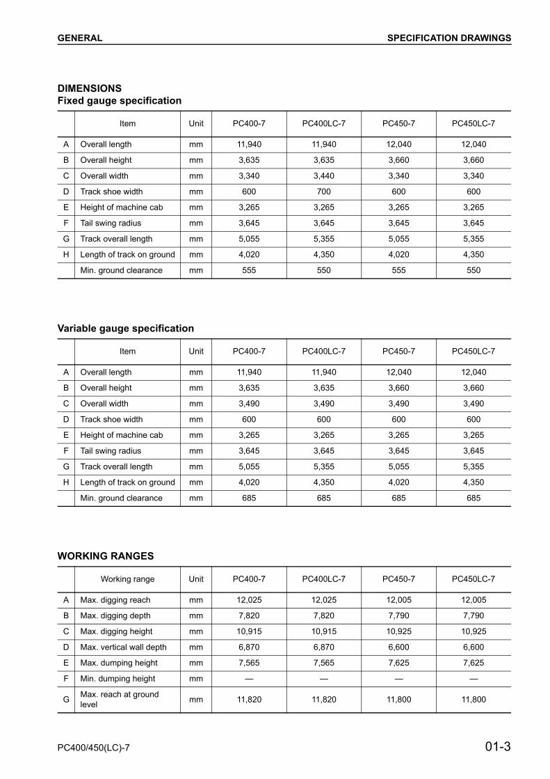
DIMENSIONSFixed gauge specification
Variable gauge specification
WORKING RANGES
Item Unit PC400-7 PC400LC-7 PC450-7 PC450LC-7
A Overall length mm 11,940 11,940 12,040 12,040
B Overall height mm 3,635 3,635 3,660 3,660
C Overall width mm 3,340 3,440 3,340 3,340
D Track shoe width mm 600 700 600 600
E Height of machine cab mm 3,265 3,265 3,265 3,265
F Tail swing radius mm 3,645 3,645 3,645 3,645
G Track overall length mm 5,055 5,355 5,055 5,355
H Length of track on ground mm 4,020 4,350 4,020 4,350
Min. ground clearance mm 555 550 555 550
Item Unit PC400-7 PC400LC-7 PC450-7 PC450LC-7
A Overall length mm 11,940 11,940 12,040 12,040
B Overall height mm 3,635 3,635 3,660 3,660
C Overall width mm 3,490 3,490 3,490 3,490
D Track shoe width mm 600 600 600 600
E Height of machine cab mm 3,265 3,265 3,265 3,265
F Tail swing radius mm 3,645 3,645 3,645 3,645
G Track overall length mm 5,055 5,355 5,055 5,355
H Length of track on ground mm 4,020 4,350 4,020 4,350
Min. ground clearance mm 685 685 685 685
Working range Unit PC400-7 PC400LC-7 PC450-7 PC450LC-7
A Max. digging reach mm 12,025 12,025 12,005 12,005
B Max. digging depth mm 7,820 7,820 7,790 7,790
C Max. digging height mm 10,915 10,915 10,925 10,925
D Max. vertical wall depth mm 6,870 6,870 6,600 6,600
E Max. dumping height mm 7,565 7,565 7,625 7,625
F Min. dumping height mm — — — —
G Max. reach at ground level mm 11,820 11,820 11,800 11,800
PC400/450(LC)-7 01-3

GENERAL SPECIFICATIONS
SPECIFICATIONSPC400-7, PC400LC-7
: The “Mi” mode is on the multi-monitor specification machine only
Machine model
PC400-7 PC400LC-7
Fixed gauge spec.
Variable gauge spec.
Fixed gauge spec.
Variable gauge spec.
Serial Number 50001 and up
Bucket capacity m3 1.4 1.4
Weight of machine kg 41,200 42,400 42,200 43,500
Perfo
rman
ce
Wor
king
rang
es
Max. digging depth
Max. vertical wall depth
Max. digging reach
Max. reach at ground level
Max. digging height
Max. dumping height
mm
mm
mm
mm
mm
mm
7,820
6,870
12,025
11,820
10,915
7,565
7,820
6,870
12,025
11,820
10,915
7,565
Max. digging force
(using power max. function)
Swing speed
Swing max. slope angle
Travel speed
Gradeability
kN {kg}
kN {kg}
rpm
deg.
km/h
deg.
256.0 {26,100}
(274.6 {28,000})
9.1
20
Lo: 3.0, Mi: 4.4, Hi: 5.5
35
256.0 {26,100}
(274.6 {28,000})
9.1
20
Lo: 3.0, Mi: 4.4, Hi: 5.5
35
Ground pressure[standard shoe width]
kPa {kg/cm2}
[mm]
77.7{0.79}
[600]
79.9 {0.82}
[600]
73.9 {0.75}
[700]
65.3 {0.67}
[700]
Dim
ensi
ons
Overall length (for transport)
Overall width
Overall width of track
Overall width of track when extended
Overall height (for transport)
Overall height to top of machine
Ground clearance of upper structure
Min. ground clearance
Tail swing radius
Min. swing radius of work equipment
Height of work equipment
at min. swing radius
Length of track on ground
Track gauge
Height of machine cab
mm
mm
mm
mm
mm
mm
mm
mm
mm
mm
mm
mm
mm
mm
11,940
3,340
3,340
—
3,635
3,265
1,320
555
3,645
4,735
9,210
4,020
2,740
3,265
11,940
3,490
2,990
3,490
3,635
3,265
1,320
685
3,645
4,735
9,210
4,020
2,890
3,265
11,940
3,440
3,440
—
3,635
3,265
1,320
555
3,645
4,735
9,210
4,020
2,740
3,265
11,940
3,490
2,990
3,490
3,635
3,265
1,320
685
3,645
4,735
9,210
4,020
2,890
3,265
01-4 PC400/450(LC)-7

GENERAL SPECIFICATIONS
Machine model PC400-7 PC400LC-7
Serial Number 50001 and up
Engi
ne
ModelType
No. of cylinders – bore × strokePiston displacement
mml {cc}
SAA6D125E-34-cycle, water-cooled, in-line, vertical, direct injection,
with turbocharger and aftercooler6 – 125 × 150
11.045 {11,045}
Perfo
rman
ce Flywheel horsepowerMax. torqueMax. speed at no loadMin. speed at no loadMin. fuel consumption
kW/rpm {HP/rpm}Nm/rpm {kgm/rpm}
rpmrpm
g/kWh {g/HPh}
246.4/1,850 {330/1,850}1,334/1,400 {136/1,400}
1,9301,000
203 {151}
Starting motorAlternatorBattery
24V, 7.5 kW24V, 35A
12V, 110 Ah × 2
Radiator core type ALW-4
Und
erca
rriag
e Carrier roller 2 on each side
Track roller 7 on each side 8 on each side
Track shoe Assembly-type triple grouser, 45 on each side
Assembly-type triple grouser, 48 on each side
Hyd
raul
ic s
yste
m
Hyd
raul
ic p
ump Type × No.
Delivery
Set pressure
l /min
MPa {kg/cm2}
HPV190+190, variable displacement, piston type x2
345 × 2
37.8 {380}
Con
trol v
alve Type × No.
Control method
6-spool type + 1-spool type × 1
Hydraulic
Hyd
raul
ic m
otor Travel motor
Swing motor
KMV200ADT-2, Variable displacement, piston type(with brake valve, parking brake): × 2
KMF230ABE-5, Fixed displacement piston type(with safety valve, holding brake, reverse rotation preventive valve): × 1
Hyd
raul
ic c
ylin
der
Boom Arm Bucket
Type Double-acting piston
Double-acting piston
Double-acting piston
Inside diameter of cylinder mm 160 185 160
Diameter of piston rod mm 110 120 110
Stroke mm 1,570 1,820 1,270
Max. distance between pins mm 3,830 4,325 3,140
Min. distance between pins mm 2,260 2,505 1,870
Hydraulic tankHydraulic filterHydraulic cooler
Closed box typeTank return side
CF40-1 (Air cooled)
PC400/450(LC)-7 01-5
GENERAL SPECIFICATIONS
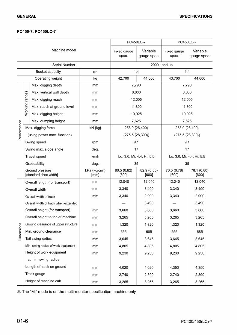
PC450-7, PC450LC-7
: The “Mi” mode is on the multi-monitor specification machine only
Machine model
PC450LC-7 PC450LC-7
Fixed gauge spec.
Variable gauge spec.
Fixed gauge spec.
Variable gauge spec.
Serial Number 20001 and up
Bucket capacity m3 1.4 1.4
Operating weight kg 42,700 44,000 43,700 44,600
Perfo
rman
ce
Wor
king
rang
es
Max. digging depth
Max. vertical wall depth
Max. digging reach
Max. reach at ground level
Max. digging height
Max. dumping height
mm
mm
mm
mm
mm
mm
7,790
6,600
12,005
11,800
10,925
7,625
7,790
6,600
12,005
11,800
10,925
7,625
Max. digging force
(using power max. function)
Swing speed
Swing max. slope angle
Travel speed
Gradeability
kN {kg}
rpm
deg.
km/h
deg.
258.9 {26,400}
(275.5 {28,300})
9.1
17
Lo: 3.0, Mi: 4.4, Hi: 5.5
35
258.9 {26,400}
(275.5 {28,300})
9.1
17
Lo: 3.0, Mi: 4.4, Hi: 5.5
35
Ground pressure[standard shoe width]
kPa {kg/cm2}[mm]
80.5 {0.82}[600]
82.9 {0.85}[600]
76.5 {0.78}[600]
78.1 {0.80}[600]
Dim
ensi
ons
Overall length (for transport)
Overall width
Overall width of track
Overall width of track when extended
Overall height (for transport)
Overall height to top of machine
Ground clearance of upper structure
Min. ground clearance
Tail swing radius
Min. swing radius of work equipment
Height of work equipment
at min. swing radius
Length of track on ground
Track gauge
Height of machine cab
mm
mm
mm
mm
mm
mm
mm
mm
mm
mm
mm
mm
mm
12,040
3,340
3,340
—
3,660
3,265
1,320
555
3,645
4,805
9,230
4,020
2,740
3,265
12,040
3,490
2,990
3,490
3,660
3,265
1,320
685
3,645
4,805
9,230
4,020
2,890
3,265
12,040
3,340
3,340
—
3,660
3,265
1,320
555
3,645
4,805
9,230
4,350
2,740
3,265
12,040
3,490
2,990
3,490
3,660
3,265
1,320
685
3,645
4,805
9,230
4,350
2,890
3,265
01-6 PC400/450(LC)-7

GENERAL SPECIFICATIONS
Machine model PC450-7 PC450LC-7
Serial Number 20001 and up
Engi
ne
ModelType
No. of cylinders – bore × strokePiston displacement
mml {cc}
SAA6D125E-34-cycle, water-cooled, in-line, vertical, direct injection,
with turbocharger and aftercooler6 – 125 × 150
11.045 {11,045}
Perfo
rman
ce
Flywheel horsepowerMax. torqueMax. speed at no loadMin. speed at no loadMin. fuel consumption
kW/rpm {HP/rpm}Nm/rpm {kgm/rpm}
rpmrpm
g/kWh {g/HPh}
246.4/1,850 {330/1,850}1,334/1,400 {136/1,400}
1,9304,000
203 {151}
Starting motorAlternatorBattery
24V, 7.5 kW24 V, 35 A
12V, 110 Ah × 2
Radiator core type ALW-4
Und
erca
rriag
e Carrier roller 2 on each side
Track roller 7 on each side 8 on each side
Track shoeAssembly-type triple grouser,
45 on each side Assembly-type triple grouser,
48 on each side
Hyd
raul
ic s
yste
m
Hyd
raul
ic p
ump Type × No.
Delivery
Set pressure
l /min
MPa {kg/cm2}
HPV190+190, ariable displacement, piston type × 2
345 × 2
37.8 {380}
Con
trol v
alve Type × No.
Control method
6-spool type + 1-spool type × 1
Hydraulic
Hyd
raul
ic m
otor Travel motor
Swing motor
KMV200ADT-2, Variable displacement, piston type(with brake valve, parking brake): × 2
KMF230ABE-5, Fixed displacement piston type × 2(with safety valve, holding brake, reverse rotation preventive valve): × 1
Hyd
raul
ic c
ylin
der Cylinder type
Inside diameter of cylinder
Outside diameter of piston rod
Stroke
Max. distance between pins
Min. distance between pins
mm
mm
mm
mm
mm
Boom Arm Bucket
Double-acting piston Double-acting piston Double-acting piston
160 185 160
110 130 110
1,570 1,985 1,270
3,830 4,325 3,140
2,260 2,505 1,870
Hydraulic tankHydraulic filterHydraulic cooler
Closed box typeTank return side
CF40-1 (Air cooled)
PC400/450(LC)-7 01-7
GENERAL WEIGHT TABLE
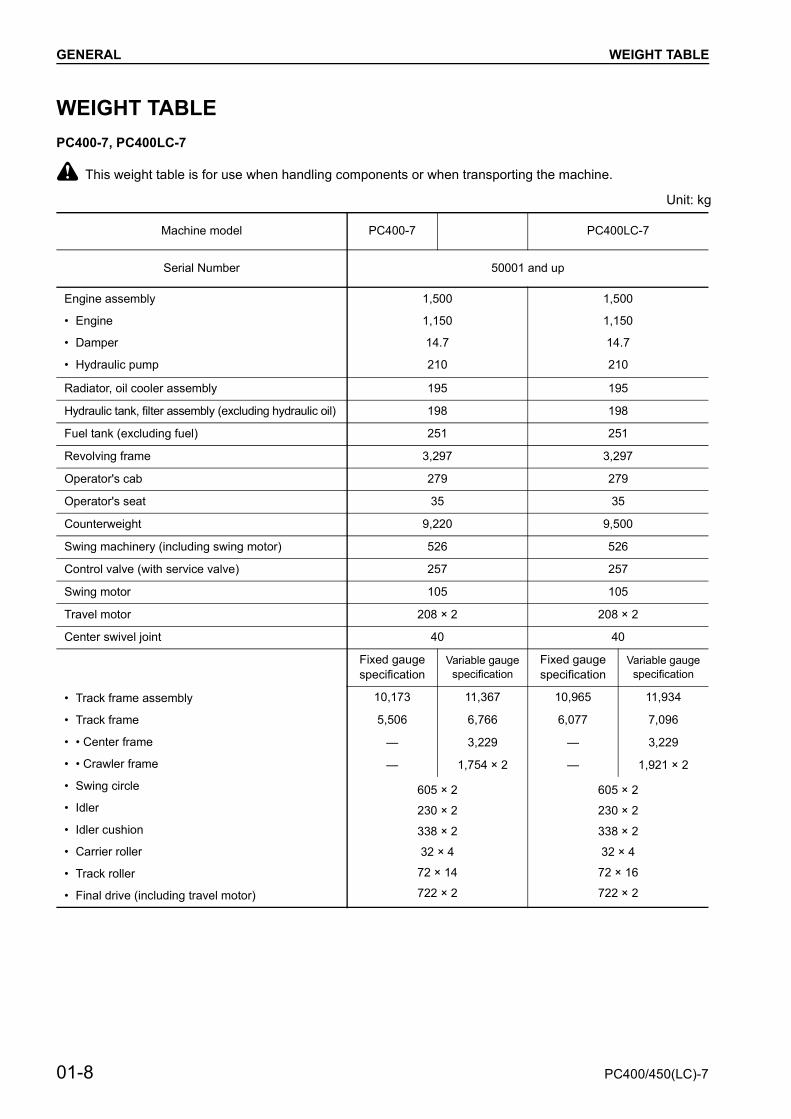
WEIGHT TABLEPC400-7, PC400LC-7
k This weight table is for use when handling components or when transporting the machine.
Unit: kg
Machine model PC400-7 PC400LC-7
Serial Number 50001 and up
Engine assembly
• Engine
• Damper
• Hydraulic pump
1,500
1,150
14.7
210
1,500
1,150
14.7
210
Radiator, oil cooler assembly 195 195
Hydraulic tank, filter assembly (excluding hydraulic oil) 198 198
Fuel tank (excluding fuel) 251 251
Revolving frame 3,297 3,297
Operator's cab 279 279
Operator's seat 35 35
Counterweight 9,220 9,500
Swing machinery (including swing motor) 526 526
Control valve (with service valve) 257 257
Swing motor 105 105
Travel motor 208 × 2 208 × 2
Center swivel joint 40 40
• Track frame assembly
• Track frame
• • Center frame
• • Crawler frame
• Swing circle
• Idler
• Idler cushion
• Carrier roller
• Track roller
• Final drive (including travel motor)
Fixed gaugespecification
Variable gaugespecification
Fixed gaugespecification
Variable gaugespecification
10,173 11,367 10,965 11,934
5,506 6,766 6,077 7,096
— 3,229 — 3,229
— 1,754 × 2 — 1,921 × 2
605 × 2
230 × 2
338 × 2
32 × 4
72 × 14
722 × 2
605 × 2
230 × 2
338 × 2
32 × 4
72 × 16
722 × 2
01-8 PC400/450(LC)-7

GENERAL WEIGHT TABLE
Unit: kg
Machine model PC400-7 PC400LC-7
Serial Number 50001 and up
Track shoe assembly
• Standard triple grouser shoe (600 mm)
• Standard triple grouser shoe (700 mm)
• Wide triple grouser shoe (800 mm)
• Wide triple grouser shoe (900 mm)
4,470
4,890
5,320
—
4,760
5,210
5,670
6,130
Boom assembly 3,290 3,290
Arm assembly 1,374 1,374
Bucket assembly 1,366 1,366
Boom cylinder assembly 355 × 2 355 × 2
Arm cylinder assembly 510 510
Bucket cylinder assembly 280 280
Link assembly 258 258
Boom pin 92 + 20 × 2 + 73 + 27 + 54 92 + 20 × 2 + 73 + 27 + 54
Arm pin 17 + 23 17 + 23
Bucket pin 38 × 2 38 × 2
Link pin 34 × 2 34 × 2
PC400/450(LC)-7 01-9

GENERAL WEIGHT TABLE
PC450-7, PC450LC-7
Unit: kg
Machine model PC450-7 PC450LC-7
Serial Number 20001 and up
Engine assembly
• Engine
• Damper
• Hydraulic pump
1,500
1,150
14.7
210
1,500
1,150
14.7
210
Radiator oil cooler assembly 195 195
Hydraulic tank, filter assembly (excluding hydraulic oil) 198 198
Fuel tank (excluding fuel) 251 251
Revolving frame 3,402 3,402
Operator’s cab 279 279
Operator’s seat 35 35
Counterweight 9,220 9,220
Swing machinery 526 526
Control valve 257 257
Swing motor 105 105
Travel motor 208 × 2 208 × 2
Center swivel joint 40 40
• Track frame assembly
• Track frame
• • Center frame
• • Crawler frame
• Swing circle
• Idler
• Idler cushion
• Carrier roller
• Track roller
• Final drive (including travel motor)
Fixed gaugespecification
Variable gauge specification
Fixed gaugespecification
Variable gauge specification
10,462 11,697 11,269 12,244
5,506 6,766 6,077 7,096
— 3,229 — 3,229
— 1,754 × 2 — 1,921 × 2
605
230 × 2
338 × 2
32 × 4
81 × 6, 72 × 8
722 × 2
605
230 × 2
338 × 2
32 × 4
81 × 8, 72 × 8
722 × 2
01-10 PC400/450(LC)-7

GENERAL WEIGHT TABLE
Unit: kg
Machine model PC450-7 PC450LC-7
Serial Number 20001 and up
Track shoe assembly
• Standard triple grouser shoe (600 mm)
• Standard triple grouser shoe (700 mm)
• Wide triple grouser shoe (800 mm)
4,470
4,890
—
4,760
5,210
—
Boom assembly 3,380 3,380
Arm assembly 1,622 1,622
Bucket assembly 1,941 1,941
Boom cylinder assembly 355 × 2 355 × 2
Arm cylinder assembly 580 580
Bucket cylinder assembly 280 280
Link assembly 258 258
Boom pin 92 + 20 × 2 + 73 + 27 + 54 92 + 20 × 2 + 73 + 27 + 54
Arm pin 17 + 23 17 + 23
Bucket pin 38 × 2 38 × 2
Link pin 34 × 2 34 × 2
PC400/450(LC)-7 01-11

GENERAL FUEL, COOLANT AND LUBRICANTS
FUEL, COOLANT AND LUBRICANTS
01-12 PC400/450(LC)-7

ENGINE RELATED PARTS..................... 10- 2RADIATOR • OIL COOLER •
AFTERCOOLER ................................ 10- 3POWER TRAIN ....................................... 10- 4FINAL DRIVE .......................................... 10- 6SWING MACHINERY.............................. 10- 8SWING CIRCLE ...................................... 10- 10TRACK FRAME AND RECOIL SPRING . 10- 12IDLER ...................................................... 10- 14CARRIER ROLLER ................................. 10- 16TRACK ROLLER ..................................... 10- 17TRACK SHOE ......................................... 10- 18HYDRAULIC PIPING DRAWING ............ 10- 22HYDRAULIC TANK.................................. 10- 24HYDRAULIC PUMP ................................ 10- 26LS(PC)-EPC VALVE ................................ 10- 44VARIABLE VOLUME VALVE .................. 10- 47CONTROL VALVE ................................... 10- 50MAIN RELIEF VALVE .............................. 10- 64CLSS ....................................................... 10- 66SELF PRESSURE REDUCING VALVE... 10- 69SWING MOTOR ...................................... 10- 72CENTER SWIVEL JOINT........................ 10- 80TRAVEL MOTOR..................................... 10- 82TRAVEL JUNCTION VALVE.................... 10- 93VALVE CONTROL ................................... 10- 95TRAVEL PPC SHUTTLE VALVE ............. 10- 96WORK EQUIPMENT • SWING PPC
VALVE ................................................ 10-100TRAVEL PPC VALVE .............................. 10-104SERVICE PPC VALVE ............................ 10- 111SOLENOID VALVE .................................. 10-112PPC ACCUMULATOR............................. 10-114RETURN OIL FILTER ............................. 10-115BOOM HYDRAULIC DRIFT
PREVENTION VALVE........................ 10-116ARM HYDRAULIC DRIFT PREVENTION
VALVE ................................................ 10-121QUICK RETURN VALVE......................... 10-125LIFT CHECK VALVE................................ 10-127ATTACHMENT CIRCUIT SELECTOR
VALVE................................................ 10-128HOLDING VALVE .................................... 10-130HYDRAULIC CYLINDER......................... 10-136WORK EQUIPMENT ............................... 10-138AIR CONDITIONER ................................ 10-144
ENGINE CONTROL.................................10-145ELECTRONIC CONTROL SYSTEM........10-151MONITOR SYSTEM.................................10-178SENSOR ..................................................10-198
10 STRUCTURE, FUNCTION AND MAINTENANCE STANDARD
PC400/450(LC)-7 10-1

STRUCTURE, FUNCTION AND MAINTENANCE STANDARD ENGINE RELATED PARTS
ENGINE RELATED PARTS
1. Drive plate 5. Damper assembly Outline• The damper assembly is a wet type.
Oil capacity: 1.3 l2. Torsion spring 6. Muffler3. Stopper pin 7. Rear engine mount4. Friction plate 8. Front engine mount
10-2 PC400/450(LC)-7

STRUCTURE, FUNCTION AND MAINTENANCE STANDARD RADIATOR • OIL COOLER • AFTERCOOLER
RADIATOR • OIL COOLER • AFTERCOOLER
1. Oil cooler 10. Condenser Specifications
Radiator : ALW-4Oil cooler : CF40-1
2. Radiator 11. Fuel cooler3. Radiator cap4. Reservoir tank5. Net6. Shroud7. Radiator inlet hose8. Radiator outlet hose9. Aftercooler
PC400/450(LC)-7 10-3

STRUCTURE, FUNCTION AND MAINTENANCE STANDARD POWER TRAIN
POWER TRAIN
1. Idler 7. Hydraulic pump (HPV190+190)2. Center swivel joint 8. Travel speed solenoid valve3. Control valve 9. Swing brake solenoid valve4. Final drive 10. Swing machinery5. Travel motor (KMV 200ADT-2) 11. Swing motor (KMF230ABE-5)6. Engine (SAA6D125-3E) 12. Swing circle
10-4 PC400/450(LC)-7


STRUCTURE, FUNCTION AND MAINTENANCE STANDARD FINAL DRIVE
FINAL DRIVE
10-6 PC400/450(LC)-7

STRUCTURE, FUNCTION AND MAINTENANCE STANDARD FINAL DRIVE
Unit: mm
No. Check item Criteria Remedy
14 Backlash between No. 1 sun gear and No. 1 planetary gear
Standard clearance Clearance limit
Replace
0.15 – 0.54 1.10
15 Backlash between No. 1 planetary gear and ring gear 0.18 – 0.66 1.30
16 Backlash between No. 2 planetary carrier and motor 0.06 – 0.24 —
17Backlash between No. 2 sun gear and No. 2 planetary gear
0.15 – 0.51 1.00
18 Backlash between No. 2 plan-etary gear and ring gear 0.17 – 0.60 1.20
19Backlash between No. 2 planetary carrier and No. 2 sun gear
0.15 – 0.54 —
20 Amount of wear on sprocket tooth Repair limit: 6
Rebuild or replace
21 Width of sprocket toothStandard size Repair limit
90 87
SpecificationReduction ratio:
– × = –68.600
1. Level plug2. Drain plug3. No. 1 planetary gear (No. of teeth: 43)4. No. 1 sun gear (No. of teeth: 10)5. No. 2 sun gear (No. of teeth: 18)6. No. 1 planetary carrier7. No. 2 planetary carrier8. Cover9. Ring gear (No. of teeth: 98)
10. Sprocket11. Floating seal12. Travel motor13. No. 2 planetary gear (No. of teeth: 38)
10 + 9810
18 + 9818
PC400/450(LC)-7 10-7

STRUCTURE, FUNCTION AND MAINTENANCE STANDARD SWING MACHINERY
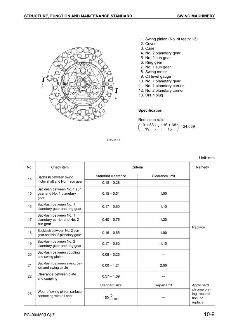
SWING MACHINERY
10-8 PC400/450(LC)-7
STRUCTURE, FUNCTION AND MAINTENANCE STANDARD SWING MACHINERY
Unit: mm
No. Check item Criteria Remedy
14 Backlash between swing motor shaft and No. 1 sun gear
Standard clearance Clearance limit
Replace
0.18 – 0.28 —
15Backlash between No. 1 sun gear and No. 1 planetary gear
0.15 – 0.51 1.00
16 Backlash between No. 1 planetary gear and ring gear 0.17 – 0.60 1.10
17Backlash between No. 1 planetary carrier and No. 2 sun gear
0.40 – 0.75 1.20
18 Backlash between No. 2 sun gear and No. 2 planetary gear 0.16 – 0.55 1.00
19 Backlash between No. 2 planetary gear and ring gear 0.17 – 0.60 1.10
20 Backlash between coupling and swing pinion 0.08 – 0.25 —
21 Backlash between swing pin-ion and swing circle 0.00 – 1.21 2.00
22 Clearance between plate and coupling 0.57 – 1.09 —
23 Wear of swing pinion surface contacting with oil seal
Standard size Repair limit Apply hard chrome plat-ing, recondi-tion, or replace
150 —
Specification
Reduction ratio:
× = 24.039
1. Swing pinion (No. of teeth: 13)2. Cover3. Case4. No. 2 planetary gear5. No. 2 sun gear6. Ring gear7. No. 1 sun gear8. Swing motor9. Oil level gauge
10. No. 1 planetary gear11. No. 1 planetary carrier12. No. 2 planetary carrier 13. Drain plug
19 + 6819
16 + 6816
0–0.100
PC400/450(LC)-7 10-9
STRUCTURE, FUNCTION AND MAINTENANCE STANDARD SWING CIRCLE
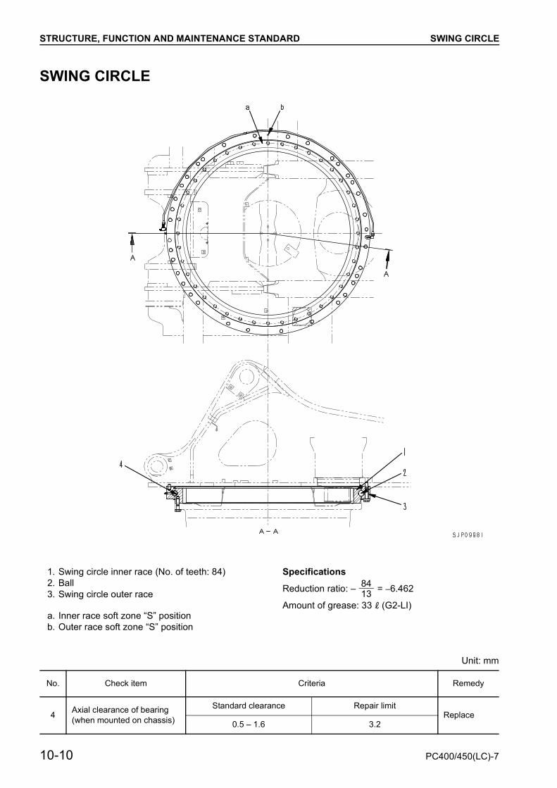
SWING CIRCLE
Specifications
Reduction ratio: – = –6.462
Amount of grease: 33 l (G2-LI)
Unit: mm
1. Swing circle inner race (No. of teeth: 84)2. Ball3. Swing circle outer race
a. Inner race soft zone “S” positionb. Outer race soft zone “S” position
8413
No. Check item Criteria Remedy
4 Axial clearance of bearing(when mounted on chassis)
Standard clearance Repair limitReplace
0.5 – 1.6 3.2
10-10 PC400/450(LC)-7


STRUCTURE, FUNCTION AND MAINTENANCE STANDARD TRACK FRAME AND RECOIL SPRING
TRACK FRAME AND RECOIL SPRING
• The dimensions and the number of track rollersdepend on the model, but the basic structure isnot different.
• Number of track rollers
1. Idler2. Track frame3. Carrier roller4. Final drive5. Track roller6. Track shoe7. Center guard8. Recoil spring9. Front guard
Model Q’ty
PC400-7, 450-7 7
PC400LC-7, 450LC-7 8
10-12 PC400/450(LC)-7
STRUCTURE, FUNCTION AND MAINTENANCE STANDARD TRACK FRAME AND RECOIL SPRING
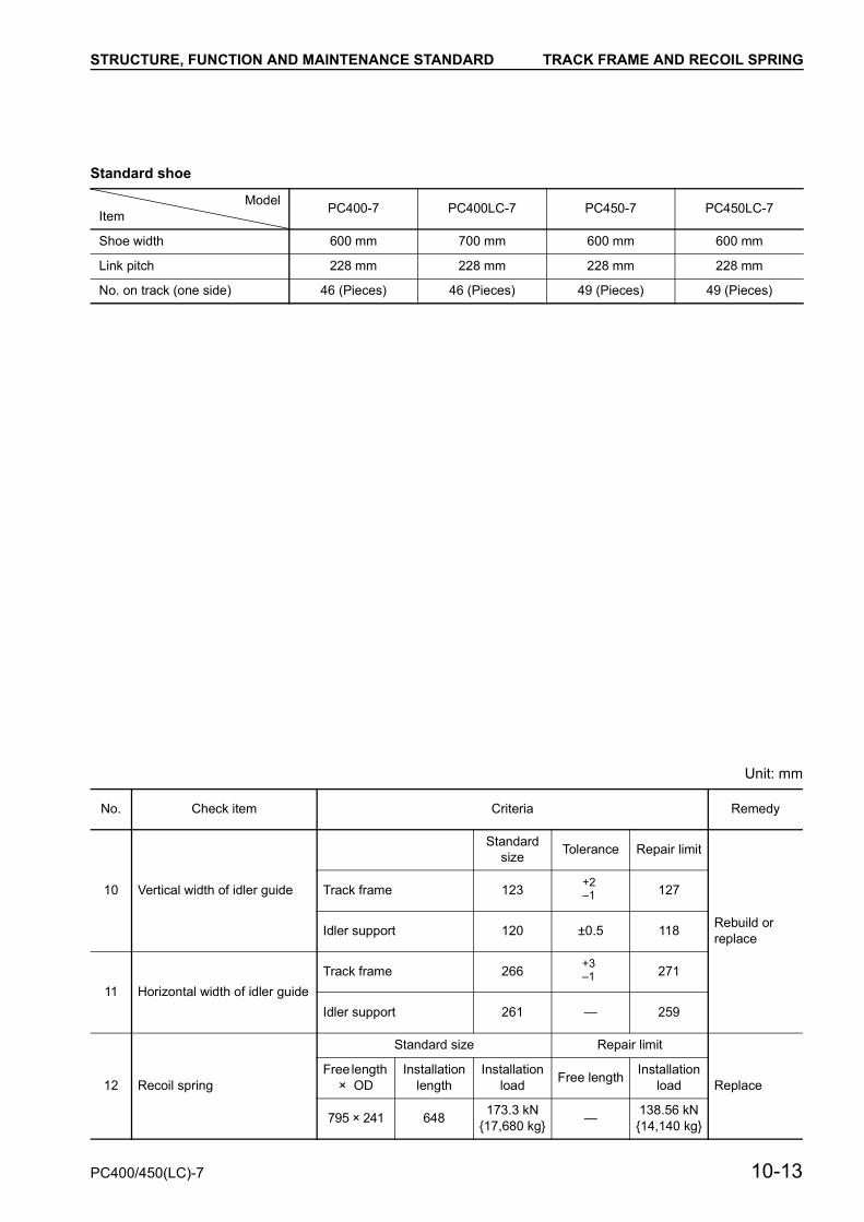
Standard shoe
Unit: mm
ModelItem PC400-7 PC400LC-7 PC450-7 PC450LC-7
Shoe width 600 mm 700 mm 600 mm 600 mm
Link pitch 228 mm 228 mm 228 mm 228 mm
No. on track (one side) 46 (Pieces) 46 (Pieces) 49 (Pieces) 49 (Pieces)
No. Check item Criteria Remedy
10 Vertical width of idler guide
Standard size Tolerance Repair limit
Rebuild or replace
Track frame 123 127
Idler support 120 ±0.5 118
11 Horizontal width of idler guideTrack frame 266 271
Idler support 261 — 259
12 Recoil spring
Standard size Repair limit
ReplaceFree length
× ODInstallation
lengthInstallation
load Free length Installation load
795 × 241 648 173.3 kN {17,680 kg} — 138.56 kN
{14,140 kg}
+2–1
+3–1
PC400/450(LC)-7 10-13
STRUCTURE, FUNCTION AND MAINTENANCE STANDARD IDLER
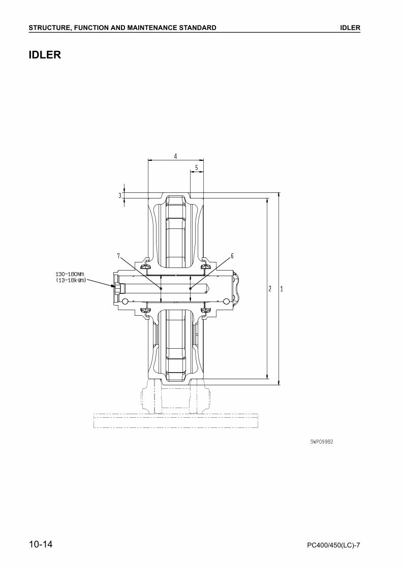
IDLER
10-14 PC400/450(LC)-7

STRUCTURE, FUNCTION AND MAINTENANCE STANDARD
Unit: mm
No. Check item Criteria Remedy
1 Outside diameter of protrud-ing
Standard size Repair limit
Rebuild or replace
704 —
2 Outside diameter of tread 660 648
3 Depth of tread 22 28
4 Total width 202 —
5 Width of tread 48.5 —
6 Clearance between shaft and bushing
Standard sizeTolerance Standard
clearance
Replace bushing
Shaft Hole
95 –0.120–0.207
+0.360+0.220 0.340 –0.507
7 Interference between idler and bushing
Standard sizeTolerance Standard
interferenceShaft Hole
102.6 +0.087+0.037
–0.027–0.079 0.064 –0.149
PC400/450(LC)-7 10-15
STRUCTURE, FUNCTION AND MAINTENANCE STANDARD CARRIER ROLLER
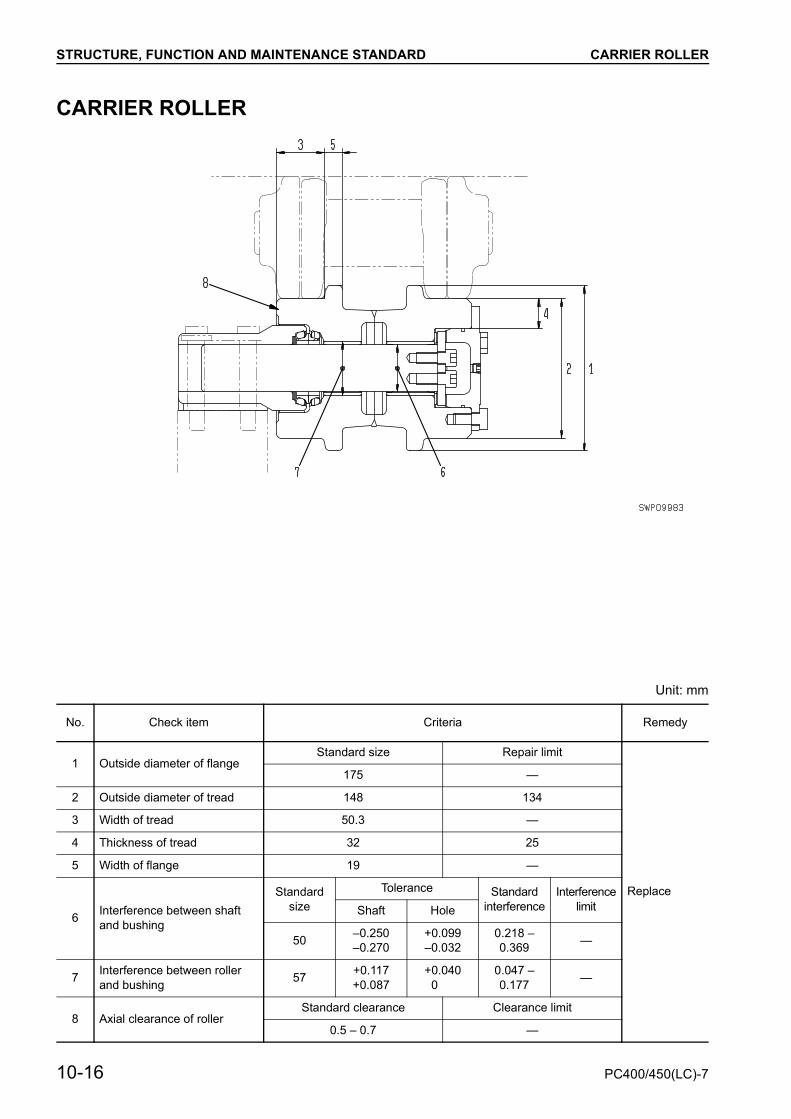
CARRIER ROLLER
Unit: mm
No. Check item Criteria Remedy
1 Outside diameter of flangeStandard size Repair limit
Replace
175 —
2 Outside diameter of tread 148 134
3 Width of tread 50.3 —
4 Thickness of tread 32 25
5 Width of flange 19 —
6 Interference between shaft and bushing
Standard size
Tolerance Standard interference
InterferencelimitShaft Hole
50 –0.250–0.270
+0.099–0.032
0.218 – 0.369 —
7 Interference between roller and bushing 57 +0.117
+0.087+0.040
00.047 –0.177 —
8 Axial clearance of rollerStandard clearance Clearance limit
0.5 – 0.7 —
10-16 PC400/450(LC)-7

STRUCTURE, FUNCTION AND MAINTENANCE STANDARD TRACK ROLLER
TRACK ROLLER
Unit: mm
No. Check item Criteria Remedy
1 Outside diameter of outer flange
Standard size Repair limit
Rebuild or replace
240 —
2 Outside diameter of inner flange(double flange) 237 —
3 Outside diameter of tread 200 188
4 Thickness of tread 56.2 50.2
5 Overall width 278 —
6 Width of treadSinge flange 54.6 —
Double flange 51.6 —
7 Width of outer flange
Singe flange 32.6 —
Double flange 32.6 —
8 Width of inner flange(Double flange) 23.0 —
9 Axial play 0.4 – 1.0 —
10 Clearance between shaft and bushing
Standard size
Tolerance Standard clearance
Clearancelimit
Replace bushing
Shaft Hole
80 –0.250–0.350
+0.174+0.029
0.279 – 0.524 1.5
11 Interference between roller and bushing
Standard size
Tolerance Standard interference
InterferencelimitShaft Hole
87.6 +0.108+0.008
–0.006–0.036
0.014 – 0.144 —
PC400/450(LC)-7 10-17
STRUCTURE, FUNCTION AND MAINTENANCE STANDARD TRACK SHOE
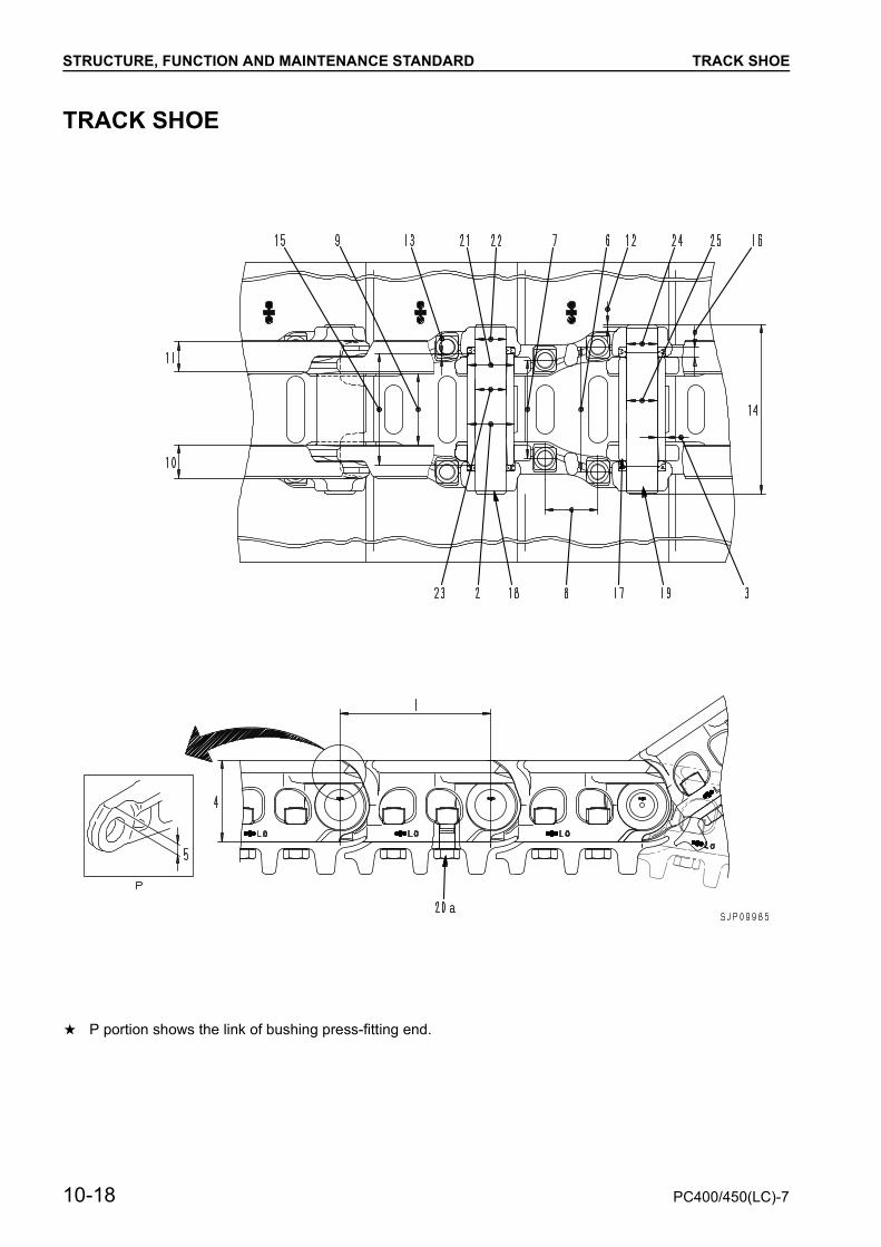
TRACK SHOETRACK SHOE
a P portion shows the link of bushing press-fitting end.
10-18 PC400/450(LC)-7

STRUCTURE, FUNCTION AND MAINTENANCE STANDARD TRACK SHOE
Unit: mm
: Dry type track link
No. Check item Criteria Remedy
1 Link pitchStandard size Repair limit
Reverse or replace
228.9 231.9
2 Bushing outside diameterStandard size When turned
71.5 66.5
3 Thickness of bushing metal 12 7 Adjust or replace
4 Link heightStandard size Repair limit
Repair or replace
129 119
5 Thickness of link metal(bushing press-fitting portion) 34.5 24.5
6
Shoe bolt pitch
184
Replace7 144
8 76.2
9
Link
Insidewidth 106
Repair or replace10 Overall
width 51.6
11 Treadwidth 44.8
12 Protrusion of pin 4.4
Adjust or replace
13 Protrusion of regular bushing 5.25
14 Overall length of pin 252
15 Overall length of bushing 164.5
16 Thickness of spacer —
17
Press-fitting force
Bushing 118 – 304 kN {12 – 31 ton}
—18 Regularpin 176 – 451 kN {18 – 46 ton}
19Master
pin 137 – 284 kN {14 – 29 ton}
PC400/450(LC)-7 10-19

STRUCTURE, FUNCTION AND MAINTENANCE STANDARD TRACK SHOE
Unit: mm
No. Check item Criteria Remedy
20Shoe bolt
a. Regular link
Tightening torque (Nm {kgm})
Additinal tightening angle (deg.)
RetightenTriple shoe 393±39 {40±4} 120±10
b. Master link
Tightening torque (Nm {kgm})
Additinal tightening angle (deg.)
Lower limit torque (Nm {kgm})
— — —
No. of shoes (each side) PC400-7, PC450-7: 46PC400LC-7, PC450LC-7: 49 —
21 Interference between bushing and link
Standard sizeTolerance Standard
interference
Adjust or replace
Shaft Hole
71 +0.494+0.454
+0.0740 0.380 – 0.494
22 Interference between regular pin and link 47 +0.235
+0.085–0.218–0.280 0.303 – 0.515
23 Clearance between regular pin and bushing
Standard sizeTolerance Standard
clearanceShaft Hole
47 +0.235+0.085
+0.915+0.415 0.180 – 0.830
24Interference between master pin and bushing
Standard sizeTolerance Standard
interferenceShaft Hole
47 +0.030
–0.218–0.280 0.218 – 0.310
25Clearance between master pin and bushing
Standard sizeTolerance Standard
clearanceShaft Hole
47 –0.2–0.4
+0.915+0.415 0.615 – 1.315
10-20 PC400/450(LC)-7

STRUCTURE, FUNCTION AND MAINTENANCE STANDARD TRACK SHOE
TRIPLE GROUSER SHOE
Unit: mm
No. Check item Criteria Remedy
1 HeightStandard size Repair limit
Rebuild or replace
37 22
2 Thickness 13
3Length at of base
33
4 27
5
Length at tip
25.5
6 17.5
7 23.5
PC400/450(LC)-7 10-21

STRUCTURE, FUNCTION AND MAINTENANCE STANDARD HYDRAULIC PIPING DRAWING
HYDRAULIC PIPING DRAWING
1. Bucket cylinder2. Arm cylinder3. Boom cylinder4. Swing motor5. Control valve6. Oil cooler7. Hydraulic filter8. Hydraulic pump9. L.H. travel motor
10. Hydraulic tank11. Multi-pattern selector valve12. L.H. PPC valve13. Safety lever (electric type)14. Center swivel joint15. R.H. PPC valve16. Travel PPC valve17. Attachment circuit selector valve18. Holding valve19. Accumulator20. Solenoid valve assembly
20A. PPC lock solenoid20B. Travel junction solenoid20C. Pump merge/divider solenoid20D. Travel speed solenoid20E. Swing brake solenoid20F. Machine push-up solenoid20G. 2-stage relief solenoid
10-22 PC400/450(LC)-7

STRUCTURE, FUNCTION AND MAINTENANCE STANDARD HYDRAULIC PIPING DRAWING
PC400/450(LC)-7 10-23

STRUCTURE, FUNCTION AND MAINTENANCE STANDARD HYDRAULIC TANK
HYDRAULIC TANK
1. Oil filler cap SpecificationsTank capacity: 335 lAmount of oil inside tank: 248 l
Pressure valve• Relief cracking pressure: 16.7 ± 6.9 kPa
{0.17 ± 0.07 kg/cm2}• Suction cracking pressure: 0 – 0.49 kPa
{0 – 0.005 kg/cm2}• Bypass valve set pressure: 150 ± 30 kPa
{1.5 ± 0.3 kg/cm2}
Breather• Intake valve set pressure: 2.0 ± 0.3 kPa
{0.02 ± 0.003 kg/cm2}• Exhaust valve set pressure: 98 ± 14.7 kPa
{1.0 ± 0.15 kg/cm2}
2. Breather3. Hydraulic tank4. Sight gauge5. Strainer6. Filter element7. Strainer8. Bypass valve
10-24 PC400/450(LC)-7


STRUCTURE, FUNCTION AND MAINTENANCE STANDARD HYDRAULIC PUMP
HYDRAULIC PUMPHPV160+160(190)
Outline• This pump consists of 2 variable capacity swash plate piston pumps, PC valve, LS valve, and EPC valve.
1. Front main pump2. Rear main pump3. LS valve4. PC valve5. LS-EPC valve6. PC-EPC valve7. Variable volume valve
IM : PC mode selector currentISIG : LS set selector currentPAF : Front pump deliveryPFC : Front pump delivery
pressure detectionPAR : Rear pump deliveryPRC : Rear pump delivery
pressure detectionPBF : Front pump pressure input PD1F : Case drain portPENF : Front pump control
pressure detectionPBR : Rear pump pressure inputPD2F : Drain plugPD2R : Drain plug
PENR : Rear pump control pressure detection port
PLSF : Front load pressure input PLSFC: Front load pressure
detection portPLSR : Rear load pressure input PLSRC: Rear load pressure
detection portPS : Pump suctionPLSCR: LS set selector pressure
detection portPM : PC set selector pressure
detection portPEPC : EPC basic pressure input PDIR : Air bleederPEPB : EPC basic pressure
detection port
10-26 PC400/450(LC)-7

STRUCTURE, FUNCTION AND MAINTENANCE STANDARD HYDRAULIC PUMP
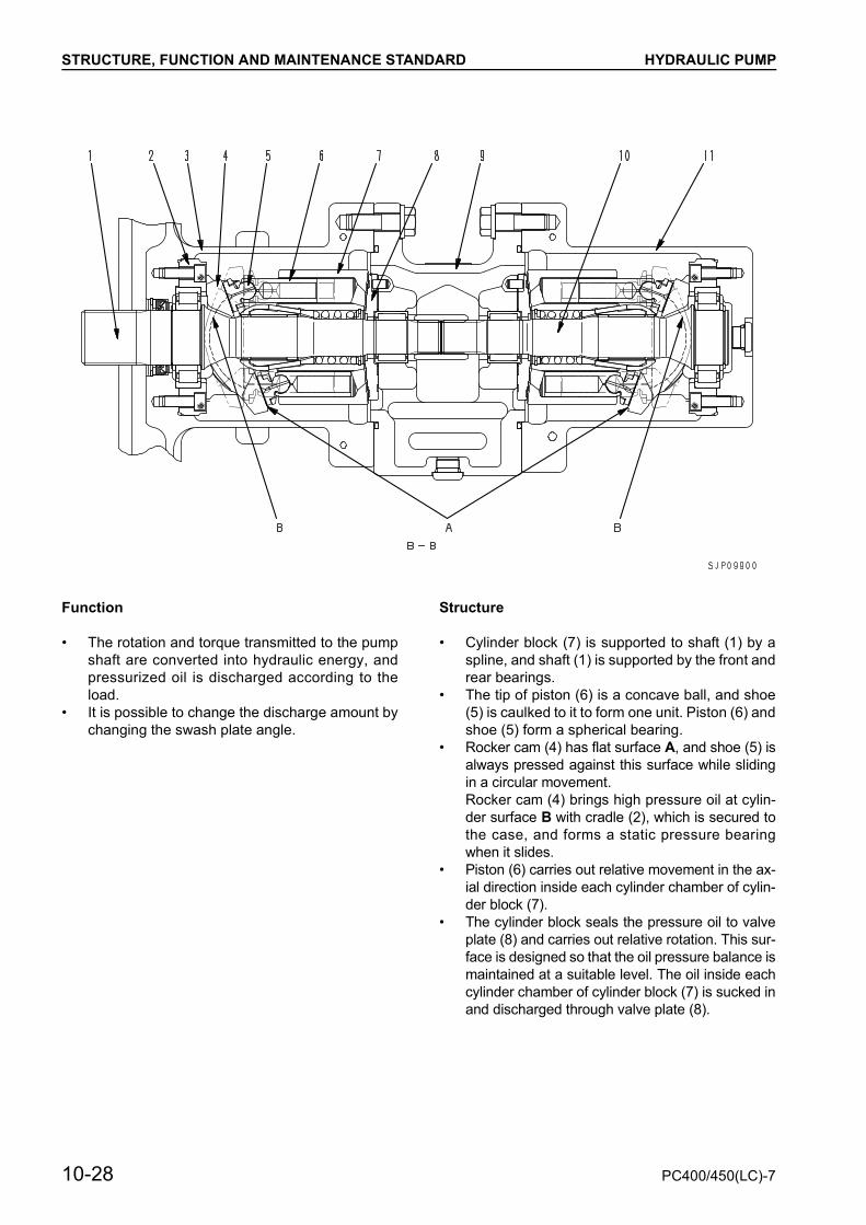
1. Shaft (Front) 7. Cylinder block2. Cradle 8. Valve plate3. Case (Front) 9. End cap4. Rocker cam 10. Shaft (Rear)5. Shoe 11. Case (Rear)6. Piston 12. Servo piston
PC400/450(LC)-7 10-27
STRUCTURE, FUNCTION AND MAINTENANCE STANDARD HYDRAULIC PUMP
Function
• The rotation and torque transmitted to the pumpshaft are converted into hydraulic energy, andpressurized oil is discharged according to theload.
• It is possible to change the discharge amount bychanging the swash plate angle.
Structure
• Cylinder block (7) is supported to shaft (1) by aspline, and shaft (1) is supported by the front andrear bearings.
• The tip of piston (6) is a concave ball, and shoe(5) is caulked to it to form one unit. Piston (6) andshoe (5) form a spherical bearing.
• Rocker cam (4) has flat surface A, and shoe (5) isalways pressed against this surface while slidingin a circular movement.Rocker cam (4) brings high pressure oil at cylin-der surface B with cradle (2), which is secured tothe case, and forms a static pressure bearingwhen it slides.
• Piston (6) carries out relative movement in the ax-ial direction inside each cylinder chamber of cylin-der block (7).
• The cylinder block seals the pressure oil to valveplate (8) and carries out relative rotation. This sur-face is designed so that the oil pressure balance ismaintained at a suitable level. The oil inside eachcylinder chamber of cylinder block (7) is sucked inand discharged through valve plate (8).
10-28 PC400/450(LC)-7
STRUCTURE, FUNCTION AND MAINTENANCE STANDARD HYDRAULIC PUMP
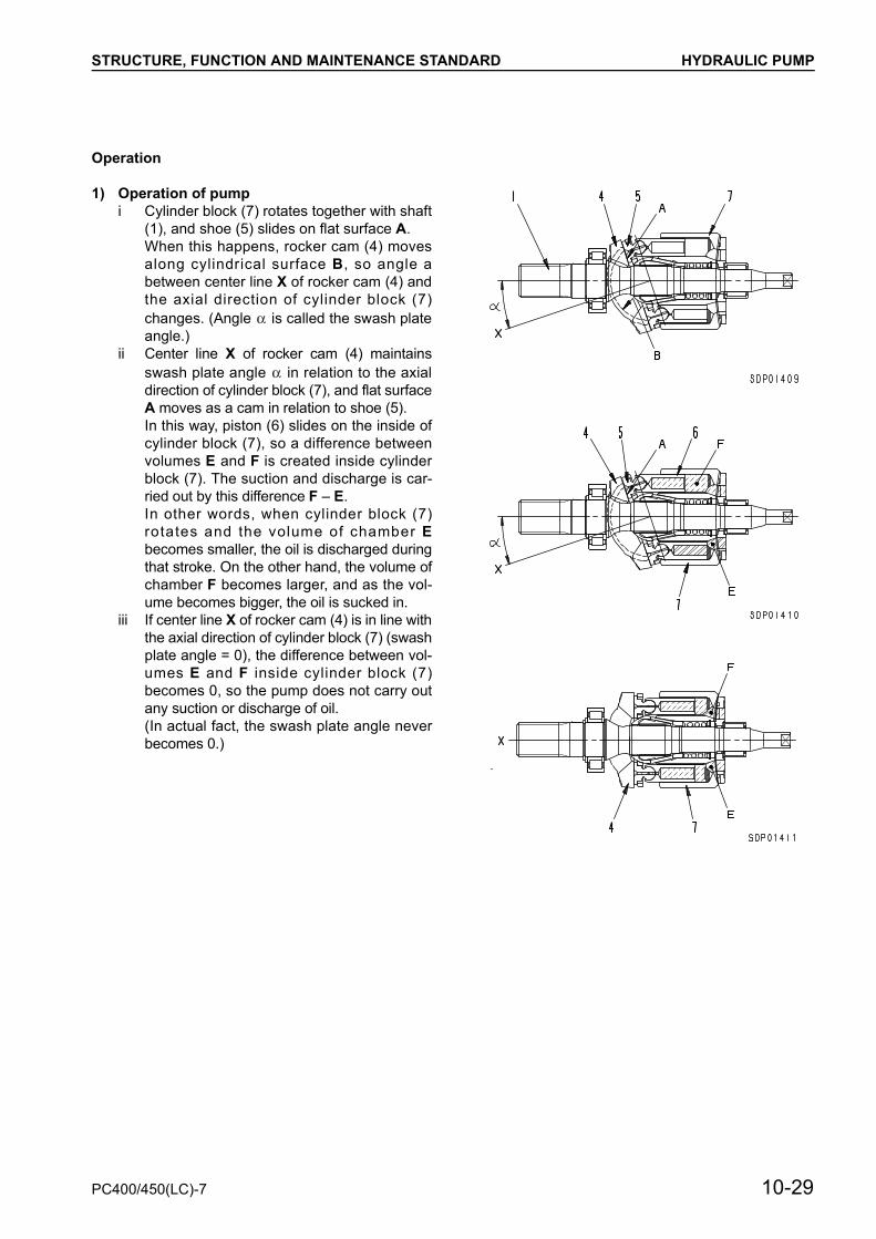
Operation
1) Operation of pumpi Cylinder block (7) rotates together with shaft
(1), and shoe (5) slides on flat surface A.When this happens, rocker cam (4) movesalong cylindrical surface B, so angle abetween center line X of rocker cam (4) andthe axial direction of cylinder block (7)changes. (Angle is called the swash plateangle.)
ii Center line X of rocker cam (4) maintainsswash plate angle in relation to the axialdirection of cylinder block (7), and flat surfaceA moves as a cam in relation to shoe (5).In this way, piston (6) slides on the inside ofcylinder block (7), so a difference betweenvolumes E and F is created inside cylinderblock (7). The suction and discharge is car-ried out by this difference F – E.In other words, when cylinder block (7)rotates and the volume of chamber Ebecomes smaller, the oil is discharged duringthat stroke. On the other hand, the volume ofchamber F becomes larger, and as the vol-ume becomes bigger, the oil is sucked in.
iii If center line X of rocker cam (4) is in line withthe axial direction of cylinder block (7) (swashplate angle = 0), the difference between vol-umes E and F inside cylinder block (7)becomes 0, so the pump does not carry outany suction or discharge of oil.(In actual fact, the swash plate angle neverbecomes 0.)
PC400/450(LC)-7 10-29

STRUCTURE, FUNCTION AND MAINTENANCE STANDARD HYDRAULIC PUMP
2) Control of discharge amount• If the swash plate angle becomes larger,
the difference between volumes E and F be-comes larger and discharge amount Q in-creases.
• Swash plate angle is changed by servopiston (12).
• Servo piston (12) moves in a reciprocalmovement ( ) according to the signal pres-sure from the PC and LS valves. Thisstraight l ine movement is transmittedthrough rod (13) to rocker cam (4), and rock-er cam (4), which is supported by the cylin-drical surface to cradle (2), slides in arotating movement in direction of arrow.
• With servo piston (12), the area receiving thepressure is different on the left and the right,so main pump discharge pressure (self pres-sure) PP is always brought to the chamberreceiving the pressure at the small diameterpiston end.
• Output pressure Pen of the LS valve isbrought to the chamber receiving the pres-sure at the large diameter end. The relation-ship in the size of pressure PP at the smalldiameter piston end and pressure Pen at thelarge diameter end, and the ratio betweenthe area receiving the pressure of the smalldiameter piston and the large diameter pis-ton controls the movement of servo piston(12).
10-30 PC400/450(LC)-7

STRUCTURE, FUNCTION AND MAINTENANCE STANDARD HYDRAULIC PUMP
LS VALVE
PC VALVE
1. Plug PA : Pump port2. Locknut PP : Pump port3. Sleeve PDP : Drain port4. Spring PLP : LS control pressure output port5. Seat PLS : LS pressure input port6. Spool PPL : PC control pressure input port7. Piston PSIG : LS mode selection pilot port8. Sleeve
1. Servo piston assembly PA : Pump port2. Plug PA2 : Pump pressure pilot port3. Pin PDP : Drain port4. Spool PM : PC mode selector pressure pilot port5. Retainer PPL : PC control pressure output port6. Seat7. Cover8. Wiring
PC400/450(LC)-7 10-31

STRUCTURE, FUNCTION AND MAINTENANCE STANDARD HYDRAULIC PUMP
Function
(1) LS valveThe LS valve detects the load and controls thedischarge amount.This valve controls main pump dischargeamount Q according to differential pressure
PLS (=PP – PLS) [called the LS differentialpressure] (the difference between main pumppressure PP and control valve outlet port pres-sure PLS).Main pump pressure PP, pressure PLS {calledthe LS pressure} coming from the control valveoutput, and pressure Psig {called the LS selec-tor pressure} from the proportional solenoidvalve enter this valve. The relationship betweendischarge amount Q and differential pressure
PLS, (the difference between main pumppressure PP and LS pressure PLS) (= PP –PLS) changes as shown in the diagram at theright according to LS pressure selector currentisig of the LS-EPC valve.When isig changes between 0 and 1A, the setpressure of the spring changes according to this,and the selector point for the pump dischargeamount changes at the rated central valvebetween 1.2 2.6 MPa {12 27 kg/cm2}.
(2) PC valveWhen the pump discharge pressure PP1 (self-pressure) and PP2 (other pump pressure) arehigh, the PC valve controls the pump so that nomore oil than the constant flow (in accordancewith the discharge pressure) flows even if thestroke of the control valve becomes larger. Inthis way, it carries out equal horsepower controlso that the horsepower absorbed by the pumpdoes not exceed the engine horsepower.In other words, If the load during the operationbecomes larger and the pump discharge pres-sure rises, it reduces the discharge amount fromthe pump; and if the pump discharge pressuredrops, it increases the discharge amount fromthe pump. The relationship between the averageof the front and rear pump discharge pressures(average discharge amount of F, R pumps (PP1+ PP2)/2) and pump discharge amount Q isshown on the right, with the current given to thePC-EPC valve solenoid shown as a parameter.The controller senses the actual speed of theengine, and if the speed drops because of anincrease in the load, it reduces the pump dis-charge amount to allow the speed to recover. Inother words, when the load increases and theengine speed drops below the set value, the command current to the PC-EPC va lve solenoid f rom the contro l le rincreases according to the drop in the enginespeed to reduce the pump swash plate angle.
10-32 PC400/450(LC)-7

STRUCTURE, FUNCTION AND MAINTENANCE STANDARD HYDRAULIC PUMP
OPERATION
(1) LS valve1) When control valve is at neutral position• The LS valve is a three-way selector valve, with
pressure PLS (LS pressure) from the inlet port ofthe control valve brought to spring chamber B,and main pump discharge pressure PP broughtto port H of sleeve (8). The size of this LS pres-sure PLS + force Z of spring (4) and the mainpump pressure (self pressure) PP determinesthe position of spool (6). However, the size of theoutput pressure PSIG (the LS selection pres-sure) of the EPC valve for the LS valve enteringport G also changes the position of spool (6).(The set pressure of the spring changes).
• Before the engine is started, servo piston (12) ispushed to the right. (See the diagram on theright)
• When the engine is started and the control leveris at the neutral position, LS pressure PLS is 0MPa {0 kg/cm2}. (It is interconnected with thedrain circuit through the control valve spool.)
At this point, spool (6) is pushed to the right, andport C and port D are connected. Pump pres-sure PP enters the large diameter end of thepiston from port K and the same pump pressurePP also enters port J at the small diameter end
of the piston, so the swash plate is moved to theminimum angle by the difference in the area ofthe piston (12).
PC400/450(LC)-7 10-33

STRUCTURE, FUNCTION AND MAINTENANCE STANDARD HYDRAULIC PUMP
2) Operation in increase direction for pump discharge amount
• When the difference between the main pumppressure PP and LS pressure PLS, in otherwords, LS differential pressure PLS, becomessmaller (for example, when the area of openingof the control valve becomes larger and pumpPP drops), spool (6) is pushed to the left by thecombined force of LS pressure PLS and theforce of spring (4).
• When spool (6) moves, port D and port E arejoined and connected to the PC valve. When thishappens, the PC valve is connected to the drainport, so circuit D – K becomes drain pressure PT.(The operation of the PC valve is explained lat-er).
• For this reason, the pressure at the large diame-ter end of servo piston (12) becomes drain pres-sure PT, and pump pressure PP enters port J atthe small diameter end, so servo piston (12) ispushed to the right. Therefore, the swash platemoves in the direction to make the dischargeamount larger. If the output pressure of the EPCvalve for the LS valve enters port G, this pres-sure creates a force to move piston (7) to theright. If piston (7) is pushed to the right, it acts tomake the set pressure of spring (4) weaker, andthe difference between PLS and PP changeswhen ports D and E of spool (6) are connected.
10-34 PC400/450(LC)-7

STRUCTURE, FUNCTION AND MAINTENANCE STANDARD HYDRAULIC PUMP
3) Operation in decrease direction for pump discharge amount
• The following explains the situation if the servopiston (12) moves to the right (the dischargeamount becomes smaller). When LS differentialpressure PLS becomes larger (for example,when the area of opening of the control valve be-comes smaller and pump pressure PP rises),pump pressure PP pushes spool (6) to the right.
• When spool (6) moves, main port pressure PPflows from port C and port D and from port K, itenters the large diameter end of the piston.
• Main pump pressure PP also enters port J at thesmall diameter end of the piston, but because ofthe difference in area between the large diameterend and the small diameter end of servo piston(12), servo piston (12) is pushed to the right.
• As a result, the swash plate moves in the direc-tion to make angle smaller.
• If LS selection pressure PSIG enters port G, itacts to make the set pressure of spring (4) weak-er.
PC400/450(LC)-7 10-35

STRUCTURE, FUNCTION AND MAINTENANCE STANDARD HYDRAULIC PUMP
4) When servo piston is balanced• Let us take the area receiving the pressure at the
large diameter end of the piston as A1, the areareceiving the pressure at the small diameter endas A0, and the pressure flowing into the large di-ameter end of the piston as Pen. If the mainpump pressure PP of the LS valve and the com-bined force of force Z of spring (4) and LS pres-sure PLS are balanced, and the relationship isA0 × PP = A1 × Pen, servo piston (11) will stopin that position, and the swash plate will be keptat an intermediate position. (It will stop at a posi-tion where the opening of the throttle from port Dto port E and from port C to port D of spool (6) isapproximately the same.)
• At this point, the relationship between the areareceiving the pressure at both ends of piston (12)is A0 : A1 = 1:2, so the pressure applied to bothends of the piston when it is balanced becomesPP : Pen = 2:1.
• The position where spool (6) is balanced andstopped is the standard center, and the force ofspring (4) is adjusted so that it is determined whenPP – PLS = 2.6 MPa {27 kg/cm2}. However, ifPSIG (the output pressure of 0 2.9 MPa {0 30 kg/cm2} of the EPC valve of the LS valve) is ap-plied to port G, the balance stop position willchange in proportion to pressure PSIG betweenPP – PLS = 2.6 1.2 MPa {27 12 kg/cm2}.
10-36 PC400/450(LC)-7
STRUCTURE, FUNCTION AND MAINTENANCE STANDARD HYDRAULIC PUMP
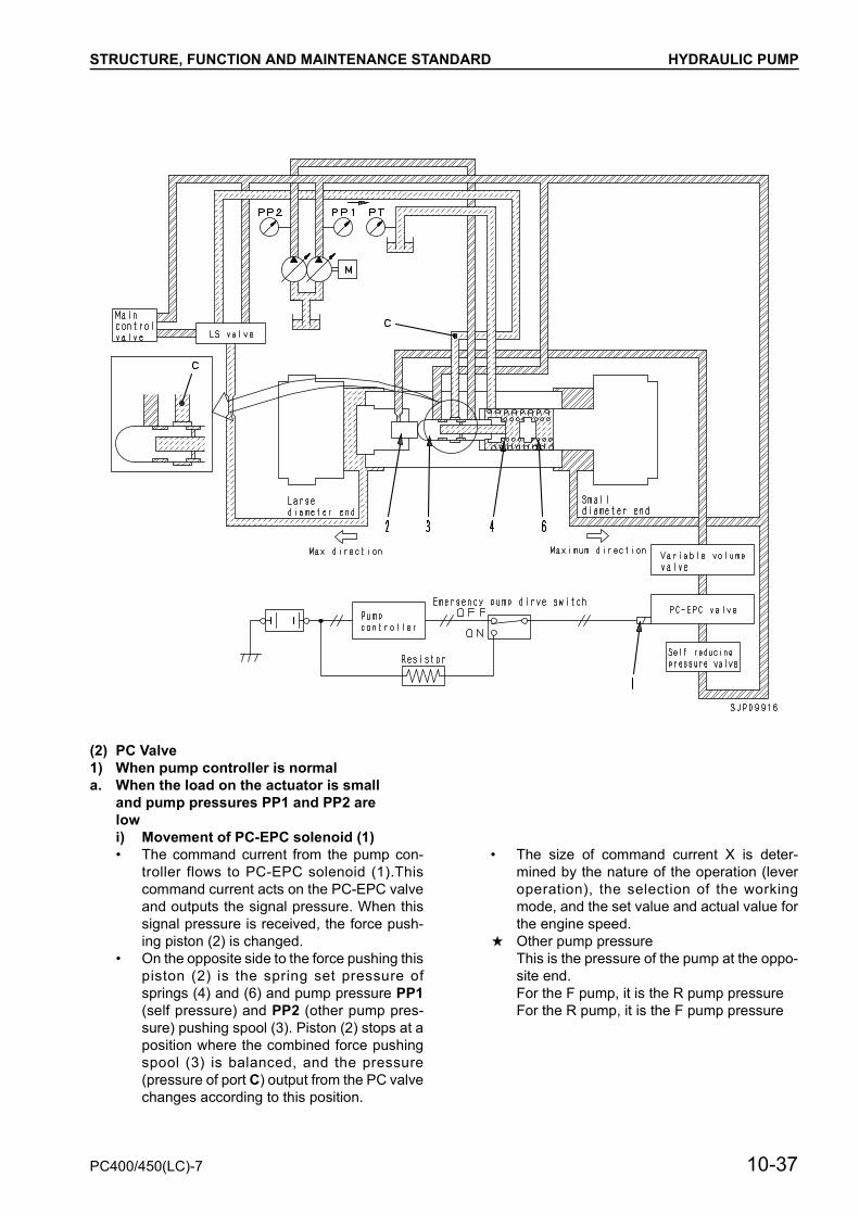
(2) PC Valve1) When pump controller is normala. When the load on the actuator is small
and pump pressures PP1 and PP2 are lowi) Movement of PC-EPC solenoid (1)• The command current from the pump con-
troller flows to PC-EPC solenoid (1).Thiscommand current acts on the PC-EPC valveand outputs the signal pressure. When thissignal pressure is received, the force push-ing piston (2) is changed.
• On the opposite side to the force pushing thispiston (2) is the spring set pressure ofsprings (4) and (6) and pump pressure PP1(self pressure) and PP2 (other pump pres-sure) pushing spool (3). Piston (2) stops at aposition where the combined force pushingspool (3) is balanced, and the pressure(pressure of port C) output from the PC valvechanges according to this position.
• The size of command current X is deter-mined by the nature of the operation (leveroperation), the selection of the workingmode, and the set value and actual value forthe engine speed.
a Other pump pressureThis is the pressure of the pump at the oppo-site end.For the F pump, it is the R pump pressureFor the R pump, it is the F pump pressure
PC400/450(LC)-7 10-37

STRUCTURE, FUNCTION AND MAINTENANCE STANDARD HYDRAULIC PUMP
ii) Action of spring• The spring load of springs (4) and (6) in the
PC valve is determined by the swash plateposition.
• If piston (9) moves to the right, spring (6) iscompressed, and if it moves further to theright, spring (6) contacts seat (5) and is fixedin position. In other words, the spring load ischanged by piston (9) extending or com-pressing springs (4) and (6).
• If the command circuit input to PC-EPCvalve solenoid (1) changes further, the forcepushing piston (2) changes, and the springload of springs (4) and (6) also changes ac-cording to the valve of the PC-EPC valve so-lenoid command current.
10-38 PC400/450(LC)-7

STRUCTURE, FUNCTION AND MAINTENANCE STANDARD HYDRAULIC PUMP
• Port C of the PC valve is connected to port Eof the LS valve (see (1) LS valve). Self pres-sure PP1 enters port B and the small diame-ter end of servo piston (9), and other pumppressure PP2 enters port A.
• When pump pressures PP1 and PP2 aresmall, spool (3) is on the left. At this point,port C and D are connected, and the pres-sure entering the LS valve becomes drainpressure PT. If port E and port G of the LSvalve are connected (see (1) LS valve), thepressure entering the large diameter end ofthe piston from port J becomes drain pres-sure PT, and servo piston (9) moves to theleft. In this way, the pump discharge amountmoves in the direction of increase.
• As servo piston (9) moves further, springs(4) and (6) expand and the spring force be-comes weaker. When the spring force be-comes weaker, spool (3) moves to the right,so the connection between port C and port Dis cut, and the pump discharge pressureports B and C are connected. As a result, thepressure at port C rises, and the pressure atthe large diameter end of the piston also ris-es, so the movement of piston (9) to the leftis stopped.
• In other words, the stop position for piston (9)(= pump discharge amount) is decided at thepoint where the force of springs (4) and (6)and the pushing force from the PC-EPCvalve solenoid and the pushing force createdby the pressures PP1 and PP2 acting on thespool (3) are in balance.
PC400/450(LC)-7 10-39

STRUCTURE, FUNCTION AND MAINTENANCE STANDARD HYDRAULIC PUMP
b. When load on actuator is large and pump discharge pressure is high• When the load is large and pump discharge
pressures PP1 and PP2 are high, the forcepushing spool (3) to the right becomes largerand spool (3) moves to the position in the di-agram above. When this happens, as shownin the diagram above, part of the pressurizedoil from port B flows out through port Cwhere the LS valve is actuated to port D, andthe pressurized oil flowing from port C to theLS valve becomes approximately half ofmain pump pressure PP.
• When port E and port G of the LS valve areconnected (see (1) LS valve), the pressurefrom port J enters the large diameter end ofservo piston (9), and servo piston (9) stops.
• If pump discharge pressure PP and PP2 in-creases further and spool (3) moves furtherto the right, main pump pressure PP1 flowsto port C and acts to make the dischargeamount the minimum. When piston (9)moves to the right, springs (4) and (6) arecompressed and push back spool (3). Whenspool (3) moves to the left, port C and port Bare disconnected and port C and port D areinterconnected. As a result, the pressure atport C (= J) drops, and piston (9) stops mov-ing to the right.
• The position in which piston (9) stops whenthis happens is further to the right than theposition when pump pressures PP1 and PP2are low.
10-40 PC400/450(LC)-7

STRUCTURE, FUNCTION AND MAINTENANCE STANDARD HYDRAULIC PUMP
• The relation of average pump pressure (PP1+ PP2)/2 and the position of servo piston (9)forms a bent line because of the double-spring effect of springs (4) and (6). The rela-tionship between average pump pressure(PP1 + PP2)/2 and pump discharge amountQ is shown in the figure at the right.
• If command voltage X sent to PC-EPC valvesolenoid (1) increases further, the relation-ship between average pump pressure (PP1+ PP2)/2, and pump discharge amount Q isproportional to the pushing force of the PC-EPC valve solenoid and moves in parallel. Inother words, the pushing force of PC-EPCsolenoid (1) is added to the force pushing tothe left because of the pump pressure ap-plied to the spool (3), so the relationship be-tween the average pump pressure (PP1 +PP2)/2 and Q moves from to in accord-ance with the increase in X.
PC400/450(LC)-7 10-41

STRUCTURE, FUNCTION AND MAINTENANCE STANDARD HYDRAULIC PUMP
2) When pump controller is abnormal and emergency pump drive switch is ON
a. When load on main pump is light• If there is a failure in the pump controller, turn
emergency pump drive switch ON to switchto the resistor side. In this case, the powersource is taken directly from the battery. Butif the current is used as it is, it is too large, souse the resistor to control the current flowingto PC-EPC valve solenoid (1).
• When this is done, the current becomes con-stant, so the force pushing piston (2) is alsoconstant.
• If the main pump pressure PP1 and PP2 arelow, the combined force of the pump pres-sure and the force of PC-EPC valve solenoid(1) is weaker than the spring set force, sospool (3) is balanced at a position to the left.
• At this point, port C is connected to the drainpressure of port D, and the large diameterend of the piston of servo piston (9) also be-comes the drain pressure PT through the LSvalve. When this happens, the pressure atthe small diameter end of the piston is large,so servo piston (9) moves in the direction tomake the discharge amount larger.
10-42 PC400/450(LC)-7

STRUCTURE, FUNCTION AND MAINTENANCE STANDARD HYDRAULIC PUMP
b. When main pump load is heavy• In the same way as in the previous item,
when the emergency pump drive switch isON, the command current sent to PC-EPCvalve solenoid (1) becomes constant. Forthis reason, the force of piston (2) pushingspool (3) is constant.
• If main pump pressures PP1 and PP2 in-crease, spool (3) moves further to the rightthan when the main pump load is light, and isbalanced at the position in the diagramabove (See Fig. P).
• In this case, the pressure from port B flowsto port C, so servo piston (9) moves to theright (to make the discharge amount smaller)by the same mechanism as explained in item2)-b, and stops at a position to the right of theposition when the load on the pump is light(See Fig. Q). In other words, even when theemergency pump drive switch is ON, thecurve for the pump pressure PP and dis-charge amount Q is determined as shown in
the diagram for the valve of the current sentto the PC-EPC valve solenoid through theresistor.The curve when the emergency pump driveswitch is ON is curve , which is to the leftof curve for when the pump controller isnormal.
PC400/450(LC)-7 10-43
STRUCTURE, FUNCTION AND MAINTENANCE STANDARD LS(PC)-EPC VALVE
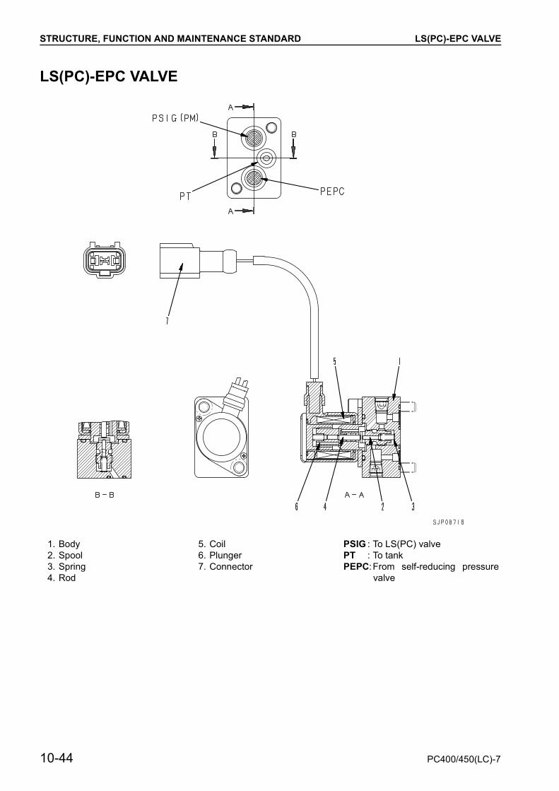
LS(PC)-EPC VALVE
1. Body 5. Coil PSIG : To LS(PC) valve2. Spool 6. Plunger PT : To tank3. Spring 7. Connector PEPC:From self-reducing pressure
valve4. Rod
10-44 PC400/450(LC)-7

STRUCTURE, FUNCTION AND MAINTENANCE STANDARD LS(PC)-EPC VALVE
Function
• The EPC valve consists of the proportional sole-noid portion and the hydraulic valve portion.
• When it receives signal current i from the pumpcontroller, it generates the EPC output pressurein proportion to the size of the signal, and outputsit to the LS valve.
Operation
1. When signal current is 0 (coil de-energized)• When there is no signal current flowing from the
controller to coil (5), coil (5) is de-energized.• For this reason, spool (2) is pushed to the left in
the direction of the arrow by spring (3).• As a result, port PEPC closes and the pressu-
rized oil from the main pump does not flow to theLS valve.At the same time, the pressurized oil from the LSvalve passes from port PSIG(PM) through portPT and is drained to the tank.
PC400/450(LC)-7 10-45

STRUCTURE, FUNCTION AND MAINTENANCE STANDARD LS(PC)-EPC VALVE
2. When signal current is very small (coil ener-gized)
• When a very small signal current flows to coil (5),coil (5) is energized, and a propulsion force isgenerated which pushes plunger (6) to the left.
• Push pin (4) pushes spool (2) to the left, andpressurized oil flows from port PEPC to portPSIG(PM).
• When the pressure at port PSIG(PM) rises andthe load of spring (3) + the force acting on sur-face a of spool (2) becomes greater than the pro-pulsion force of plunger (6), spool (2) is pushedto the right. The circuit between port PEPC andport PSIG(PM) is shut off, and at the same time,port PSIG(PM) and port PT are connected.
• As a result, spool (2) is moved up or down untilthe propulsion force of plunger (6) is balancedwith the load of spring (3) + pressure of portPSIG(PM).
• Therefore, the circuit pressure between the EPCvalve and the LS valve is controlled in proportionto the size of the signal current.
3. When signal current is maximum (coil ener-gized)
• When the signal current flows to coil (5), coil (5)is energized.
• When this happens, the signal current is at itsmaximum, so the propulsion force of plunger (6)is also at its maximum.
• For this reason, spool (2) is pushed fully to theleft by push pin (4).
• As a result, the maximum flow of pressurized oilfrom port PEPC flows to port PSIG(PM), and thecircuit pressure between the EPC valve and LSvalve becomes the maximum.At the same time, port PT closes and stops theoil from flowing to the tank.
10-46 PC400/450(LC)-7

STRUCTURE, FUNCTION AND MAINTENANCE STANDARD VARIABLE VOLUME VALVE
VARIABLE VOLUME VALVE
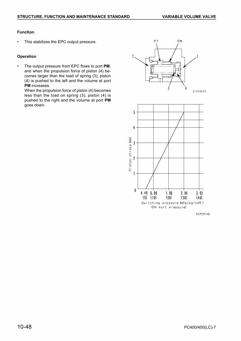
1. Block PM : To PC valve2. Plug PT : To tank3. Spring PEPC:From self-reducing pressure valve4. Piston
PC400/450(LC)-7 10-47
STRUCTURE, FUNCTION AND MAINTENANCE STANDARD VARIABLE VOLUME VALVE
Function
• This stabilizes the EPC output pressure.
Operation
• The output pressure from EPC flows to port PM,and when the propulsion force of piston (4) be-comes larger than the load of spring (3), piston(4) is pushed to the left and the volume at portPM increases.When the propulsion force of piston (4) becomesless than the load on spring (3), piston (4) ispushed to the right and the volume at port PMgoes down.
10-48 PC400/450(LC)-7


STRUCTURE, FUNCTION AND MAINTENANCE STANDARD CONTROL VALVE
CONTROL VALVE1. 6-spool valve2. Cover 13. Cover 24. Pump merge-divider valve5. Back pressure valve6. Boom lock valve7. Boom, arm Hi valve8. Quick return valve9. Boom Hi check valve
Outline• This control valve consists of a 7-spool valve (6
spool valve + boom • arm Hi valve). A merge-di-vider valve, back-pressure valve, boom hydraulicdrift prevention valve, quick return valve, and Hivalve check valve are installed to it.
• Since all the valves are assembled together withconnecting bolts and their passes are connectedto each other inside the assembly, the assemblyis small in size and easy to maintain.
• Since one spool of this control valve is used forone work equipment unit, its structure is simple.
A1 : To bucket cylinder bottom P11 : From arm PPC valveA2 : o left travel motor P12 : From arm PPC valveA3 : To boom cylinder bottom BP1 : Boom RAISE PPC output pressureA4 : To swing motor PB5 : From 2-stage safety valve solenoid valveA5 : To right travel motor PLS1 : To rear pump controlA6 : To arm cylinder head PLS2 : To front pump controlA-1 : To boom cylinder bottom PP1 : To rear pump controlA-2 : To attachment PP2 : To front pump controlB1 : To bucket cylinder head PPS1 : From rear main pumpB3 : To bottom cylinder head PPS2 : From front main pumpB4 : To swing motor PR : To solenoid valve, PPC valve, EPC valveB5 : To right travel motor PS : From pump merge-divider solenoid valveB6 : To arm cylinder bottom PST : From travel junction valveB-1 : To arm cylinder bottom PX1 : From 2-stage solenoid valveP1 : From bucket PPC valve PX2 : From 2-stage solenoid valveP2 : From bucket PPC valve SA : Pressure sensor fitting portP3 : From left travel PPC valve SB : Pressure sensor fitting portP4 : From left travel PPC valve T : To tankP5 : From boom PPC valve T1 : To tankP6 : From boom PPC valve TS : To tankP7 : From swing PPC valve TSW : To swing motorP8 : From swing PPC valveP9 : From right travel PPC valveP10 : From right travel PPC valve
10-50 PC400/450(LC)-7

STRUCTURE, FUNCTION AND MAINTENANCE STANDARD CONTROL VALVE
7-spool valve(1/9)
PC400/450(LC)-7 10-51

STRUCTURE, FUNCTION AND MAINTENANCE STANDARD CONTROL VALVE
(2/9)
10-52 PC400/450(LC)-7

STRUCTURE, FUNCTION AND MAINTENANCE STANDARD CONTROL VALVE
(3/9)
1. Unload valve 9. Pressure compensation valve (Arm IN)2. Pressure compensation valve (Arm OUT) 10. Pressure compensation valve (Bucket DUMP)3. Pressure compensation valve (Right travel re-
verse)11. Pressure compensation valve (Left travel forward)12. Pressure compensation valve (Boom LOWER)
4. Pressure compensation valve (Left swing) 13. Pressure compensation valve (Right swing)5. Pressure compensation valve (Boom RAISE) 14. Pressure compensation valve (Right travel for-
ward)6. Pressure compensation valve (Left travel reverse)7. Pressure compensation valve (Bucket CURL) 15. Pressure compensation valve (Arm IN)8. Pressure compensation valve (Boom RAISE) 16. Main relief valve
PC400/450(LC)-7 10-53

STRUCTURE, FUNCTION AND MAINTENANCE STANDARD CONTROL VALVE
(4/9)
Unit: mm
1. Spool (Arm) 6. Spool (Bucket)2. Spool (Right travel) 7. Spool (Boom Hi)3. Spool (Swing) 8. Spool (Arm Hi)4. Spool (Boom) 9. Unload valve5. Spool (Left travel) 10. Main relief valve
No. Check item Criteria Remedy
11 Spool return spring
Standard size Repair limit
If damaged or deformed, replace spring
Free length × OD
Installed length
Installed load
Free length
Installed load
54.2 × 34.8 51.2 416.5 N{42.5 kg} — 333.2 N
{34 kg}
12 Spool return spring 54.6 × 34.8 51.2 429.9 N{42.9 kg} — 336.1 N
{34.3 kg}
13 Spool return spring 54.5 × 34.8 51.2 393 N{40.1 kg} — 314.6 N
{32.1 kg}
14 Spool return spring 54.9 × 24.2 51.2 251 N{25.1 kg} — 201.0 N
{20.5 kg}
15 Spool return spring 57.2 × 32.8 51 416 N{42.5 kg} — 333.2 N
{34.0 kg}
10-54 PC400/450(LC)-7

STRUCTURE, FUNCTION AND MAINTENANCE STANDARD CONTROL VALVE
(5/9)
Unit: mm
1. Safety-suction valve (Arm OUT) 9. Safety-suction valve (2-stage) (Boom LOWER)2. Suction valve (Right travel reverse) 10. Suction valve (Right travel forward)3. Suction valve (Boom RAISE) 11. Safety-suction valve (Arm IN)4. Suction valve (Left travel reverse) 12. LS shuttle valve (Arm, right travel)5. Safety-suction valve (Boom Hi) 13. LS select valve6. Safety-suction valve (Arm IN) 14. LS shuttle valve (Boom, left travel, bucket)7. Safety-suction valve (Bucket DUMP) 15. LS check valve8. Suction valve (Left travel forward) 16. Pressure relief plug
No. Check item Criteria Remedy
17 Check valve spring
Standard size Repair limit
If damaged or deformed, replace spring
Free length × OD
Installed length
Installed load
Free length
Installed load
11.5 × 4.6 8.5 1.5 N{0.15 kg} — 1.2 N
{0.12 kg}
PC400/450(LC)-7 10-55

STRUCTURE, FUNCTION AND MAINTENANCE STANDARD CONTROL VALVE
(6/9)
ARM CONTROL VALVE R. H. TRAVEL CONTROL VALVE
1. Unload valve 5. Safety-suction valve 12. Suction valve2. Main relief valve 6. Spool 13. Spool3. Safety valve (Boom RAISE) 7. Pressure compensation valve
(OUT)14. Pressure compensation valve
(Reverse)4. Lift check valve8. LS shuttle valve 15. LS shuttle valve9. Pressure compensation valve
(IN)16. Pressure compensation valve
(Forward)10. Safety-suction valve 17. Suction valve11. Check valve for regeneration
circuit
10-56 PC400/450(LC)-7
STRUCTURE, FUNCTION AND MAINTENANCE STANDARD CONTROL VALVE
Unit: mm
No. Check item Criteria Remedy
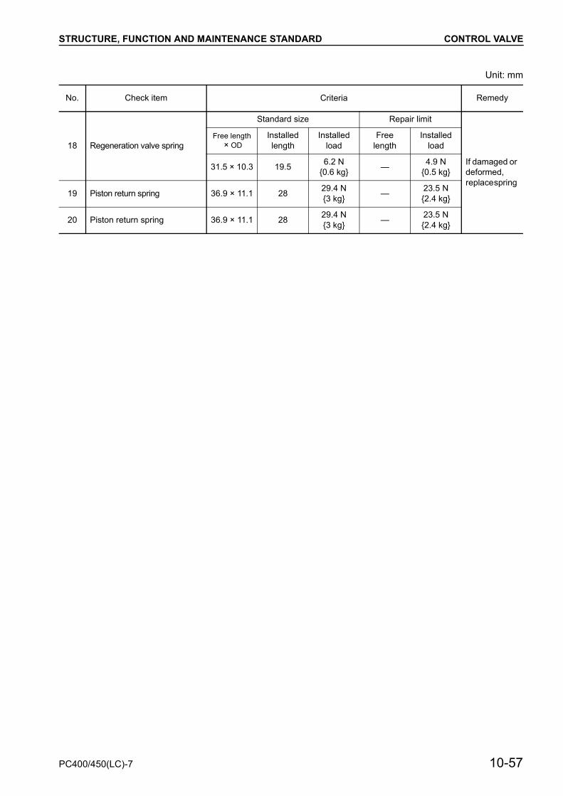
18 Regeneration valve spring
Standard size Repair limit
If damaged or deformed, replace spring
Free length × OD
Installed length
Installed load
Free length
Installed load
31.5 × 10.3 19.5 6.2 N{0.6 kg} — 4.9 N
{0.5 kg}
19 Piston return spring 36.9 × 11.1 28 29.4 N{3 kg} — 23.5 N
{2.4 kg}
20 Piston return spring 36.9 × 11.1 28 29.4 N{3 kg} — 23.5 N
{2.4 kg}
PC400/450(LC)-7 10-57

STRUCTURE, FUNCTION AND MAINTENANCE STANDARD CONTROL VALVE
(7/9)
SWING CONTROL VALVE
1. Spool2. Pressure compensation valve
(Left)3. LS select valve4. Pressure compensation valve
(Right)
ARM CONTROL VALVE
5. Suction valve6. Spool7. Pressure compensation valve
(RAISE)8. Hydraulic drift prevention valve9. LS shuttle valve
10. Pressure compensation valve(Lower)
11. Safety-suction valve12. Check valve for regeneration
circuit
L. H. TRAVEL CONTROL VALVE
13. Pump merge-divider valve (Travel junction valve)
14. Return spring15. Suction valve16. Spool17. Pressure compensation valve
(Reverse)18. LS shuttle valve19. Pressure compensation valve
(Forward)20. Suction valve
10-58 PC400/450(LC)-7

STRUCTURE, FUNCTION AND MAINTENANCE STANDARD CONTROL VALVE
Unit: mm
No. Check item Criteria Remedy
21 Regeneration valve spring
Standard size Repair limit
If damaged or deformed, replace spring
Free length × OD
Installed length
Installed load
Free length
Installed load
31.5 × 10.3 19.5 6.2 N{0.6 kg} — 4.9 N
{0.5 kg}
22 Piston return spring 48.1 × 10.8 28 17.5 N{1.8 kg} — 14.0 N
{1.4 kg}
23 Piston return spring 36.9 × 11.1 28 29.4 N{3 kg} — 23.5 N
{2.4 kg}
24 Spool return spring 30.7 × 20.5 23 50.0 N{5.1 kg} — 40.0 N
{4.1 kg}
PC400/450(LC)-7 10-59

STRUCTURE, FUNCTION AND MAINTENANCE STANDARD CONTROL VALVE
(8/9)
Unit: mm
BUCKET CONTROL VALVE
1. Safety-suction valve2. Spool3. Pressure compensation valve (CURL)4. LS shuttle valve5. Pressure compensation valve (DUMP)6. Safety-suction valve
BOOM, ARM HI VALVE
7. Boom Hi spool8. Pressure compensation valve (Boom RAISE)9. Boom Hi check valve
10. Quick-return valve11. Pressure compensation valve (Arm IN)12. Arm Hi spool13. Safety-suction valve
No. Check item Criteria Remedy
14 Piston return spring
Standard size Repair limit
If damaged or deformed, replace spring
Free length × OD
Installed length
Installed load
Free length
Installed load
48.1 × 10.8 28 17.5 N{1.8 kg} — 14.0 N
{1.4 kg}
15 Piston return spring 36.9 × 11.1 28 29.4 N{3 kg} — 23.5 N
{2.4 kg}
10-60 PC400/450(LC)-7

STRUCTURE, FUNCTION AND MAINTENANCE STANDARD CONTROL VALVE
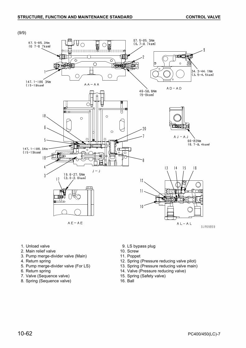
(9/9)
1. Unload valve 9. LS bypass plug2. Main relief valve 10. Screw3. Pump merge-divider valve (Main) 11. Poppet4. Return spring 12. Spring (Pressure reducing valve pilot)5. Pump merge-divider valve (For LS) 13. Spring (Pressure reducing valve main)6. Return spring 14. Valve (Pressure reducing valve)7. Valve (Sequence valve) 15. Spring (Safety valve)8. Spring (Sequence valve) 16. Ball
10-62 PC400/450(LC)-7
STRUCTURE, FUNCTION AND MAINTENANCE STANDARD CONTROL VALVE
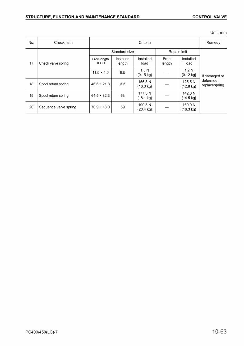
Unit: mm
No. Check item Criteria Remedy
17 Check valve spring
Standard size Repair limit
If damaged or deformed, replace spring
Free length × OD
Installed length
Installed load
Free length
Installed load
11.5 × 4.6 8.5 1.5 N{0.15 kg} — 1.2 N
{0.12 kg}
18 Spool return spring 46.6 × 21.8 3.3 156.8 N{16.0 kg} — 125.5 N
{12.8 kg}
19 Spool return spring 64.5 × 32.3 63 177.5 N{18.1 kg} — 142.0 N
{14.5 kg}
20 Sequence valve spring 70.9 × 18.0 59 199.8 N{20.4 kg} — 160.0 N
{16.3 kg}
PC400/450(LC)-7 10-63

STRUCTURE, FUNCTION AND MAINTENANCE STANDARD MAIN RELIEF VALVE
MAIN RELIEF VALVE
Function
• The relief valve set pressure is set to 2 stages.When power is needed, pilot pressure P is turnedON and the pressure is set to high pressure.
Operation
• The relief valve set pressure is determined by theinstalled load of spring (1). (First stage)
• It is unnecessary to set the first and secondstage individually.The second stage is set when the first stage isset.
1. When pilot pressure P is OFF: Low-pressuresettingThe set pressure is determined by the installedload of spring (1).
2. When pilot pressure P is ON: High-pressure set-tingIn addition to the installed load of spring (1), pilotpressure P is applied to poppet diameter d1, sothe set pressure becomes higher.
1. Spring2. Poppet
10-64 PC400/450(LC)-7


STRUCTURE, FUNCTION AND MAINTENANCE STANDARD CLSS
CLSSOUTLINE OF CLSS
Features
• CLSS stands for Closed center Load SensingSystem, and has the following features.
1) Fine control not influenced by load2) Control enabling digging even with fine control3) Ease of compound operation ensured by flow
divider function using area of opening of spoolduring compound operations
4) Energy saving using variable pump control
Structure
• The CLSS consists of a main pump (2 pumps),control valve, and actuators for the work equip-ment.
• The main pump body consists of the pump itself,the PC valve and LS valve.
10-66 PC400/450(LC)-7
STRUCTURE, FUNCTION AND MAINTENANCE STANDARD CLSS
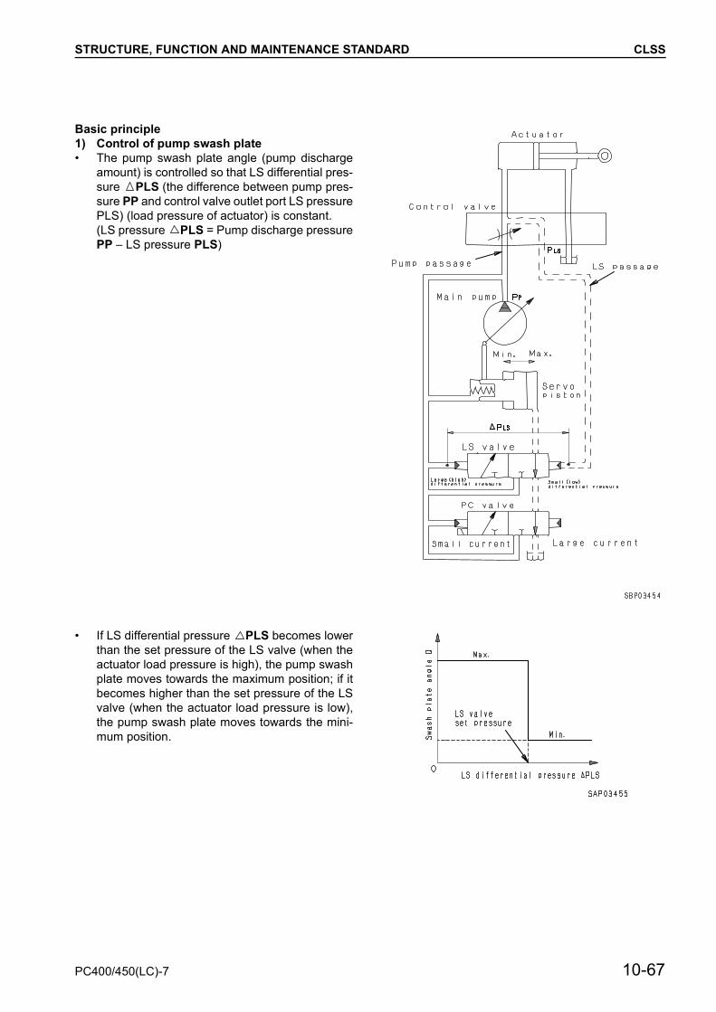
Basic principle1) Control of pump swash plate• The pump swash plate angle (pump discharge
amount) is controlled so that LS differential pres-sure PLS (the difference between pump pres-sure PP and control valve outlet port LS pressurePLS) (load pressure of actuator) is constant.(LS pressure PLS = Pump discharge pressurePP – LS pressure PLS)
• If LS differential pressure PLS becomes lowerthan the set pressure of the LS valve (when theactuator load pressure is high), the pump swashplate moves towards the maximum position; if itbecomes higher than the set pressure of the LSvalve (when the actuator load pressure is low),the pump swash plate moves towards the mini-mum position.
PC400/450(LC)-7 10-67

STRUCTURE, FUNCTION AND MAINTENANCE STANDARD CLSS
2) Pressure compensation• A pressure compensation valve is installed to the
outlet port side of the control valve to balance theload.
• When two actuators are operated together, thisvalve acts to make pressure difference P be-tween the upstream (inlet port) and downstream(outlet port) of the spool of each valve the sameregardless of the size of the load (pressure).
In this way, the flow of oil from the pump is divid-ed (compensated) in proportion to the area ofopening S1 and S2 of each valve.
10-68 PC400/450(LC)-7
STRUCTURE, FUNCTION AND MAINTENANCE STANDARD SELF PRESSURE REDUCING VALVE
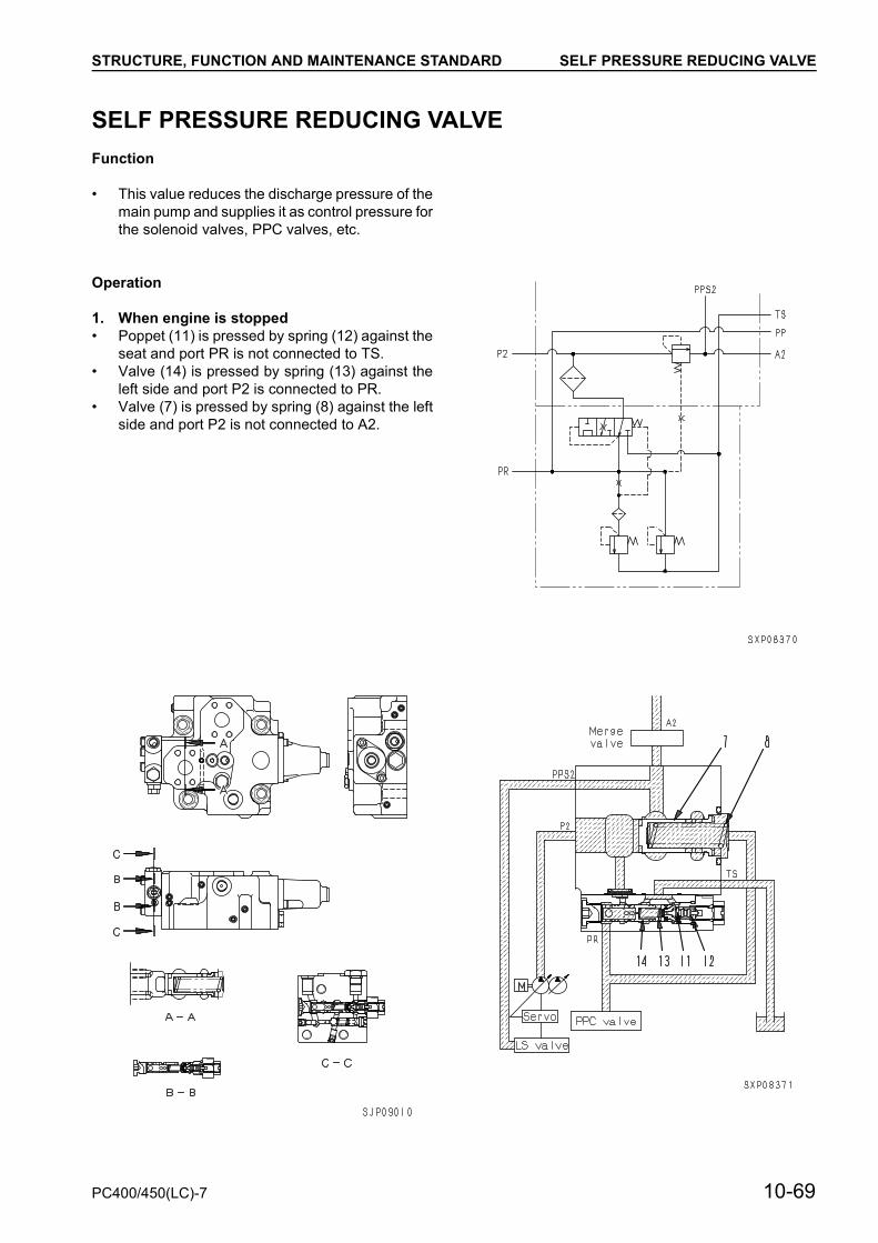
SELF PRESSURE REDUCING VALVEFunction
• This value reduces the discharge pressure of themain pump and supplies it as control pressure forthe solenoid valves, PPC valves, etc.
Operation
1. When engine is stopped• Poppet (11) is pressed by spring (12) against the
seat and port PR is not connected to TS.• Valve (14) is pressed by spring (13) against the
left side and port P2 is connected to PR.• Valve (7) is pressed by spring (8) against the left
side and port P2 is not connected to A2.
PC400/450(LC)-7 10-69

STRUCTURE, FUNCTION AND MAINTENANCE STANDARD SELF PRESSURE REDUCING VALVE
2. When in neutral or load pressure P2 is low(When boom is lowered and arm is in IN positionand they are moving down under own weight)
Note: When load pressure A2 is lower than self-pressure reducing valve output pressurePR.
• Valve (7) receives the force of spring (8) and PRpressure (which is 0 MPa {0 kg/cm2} when theengine is stopped) in the direction to close thecircuit between ports P2 and A2. If the hydraulicoil flows in port P2, the fdx P2 pressure becomesequal to the total of the force of spring (8) and thevalue of area of ød × PR pressure, then the areaof the pass between ports P2 and A2 is so ad-justed that the P2 pressure will be kept constantabove the PR pressure.
• If the PR pressure rises above the set level, pup-pet (11) opens and the hydraulic oil flows fromthe PR port through orifice “a” in spool (14) andopen part of poppet (11) to seal drain port TS.Accordingly, differential pressure is generatedbetween before and after orifice “a” in spool (14)and then spool (14) moves to close the pass be-tween port P2 and PR. The P2 pressure is con-trolled constant (at the set pressure) by the areaof the oil pass at this time and supplied as the PRpressure.
3. When load pressure P2 is high• If load pressure A2 rises and the pump discharge
increases because of operation of the workequipment, the fdx P2 pressure rises higher thanthe total of the force of spring (8) and the value ofød × PR pressure, and then valve (7) moves tothe right stroke end.
• As a result, the area of the pass between portsP2 and A2 increases and the pass resistancelowers and the loss of the engine power is re-duced.
• If the PR pressure rises above the set pressure,poppet (11) opens and the hydraulic oil flowsfrom the PR port through orifice “a” in spool (14)and open part of poppet (11) to seal drain portTS.Accordingly, differential pressure is generatedbetween before and after orifice “a” in spool (14)and then spool (14) moves to close the pass be-tween port P2 and PR. The P2 pressure is con-trolled constant (at the set pressure) by the areaof the oil pass at this time and supplied as the PRpressure.
10-70 PC400/450(LC)-7

STRUCTURE, FUNCTION AND MAINTENANCE STANDARD SELF PRESSURE REDUCING VALVE
4. When abnormally high pressure is generated• If the PR pressure on the self-pressure reducing
valve rises high abnormally, ball (16) separatesfrom the seat against the force of spring (15) andthe hydraulic oil flows from output port PR to TS.Accordingly, the PR pressure lowers. By this op-eration, the hydraulic devices (PPC valves, sole-noid valves, etc.) are protected from abnormalpressure.
PC400/450(LC)-7 10-71

STRUCTURE, FUNCTION AND MAINTENANCE STANDARD SWING MOTOR
SWING MOTORKMF230ABE-5
Specifications
B : From swing lock solenoid valveS : From control valveT : To tankMA : From control valveMB : From control valve
Model KMF230ABE-5
Theoretical displace-ment 229.4 cm³/rev
Safety valve set pressure
27.9 MPa{285 kg/cm2}
Rated revolving speed 1,413 rpm
Brake release pressure 1.9 ± 0.4 MPa {19 ± 4 kg/cm2}
+0.5+0
+0.5+0
10-72 PC400/450(LC)-7


STRUCTURE, FUNCTION AND MAINTENANCE STANDARD SWING MOTOR
1. Brake spring 8. Housing 15. Safety valve2. Drive shaft 9. Piston 16. Check valve3. Spacer 10. Cylinder block 17. Shuttle valve4. Case 11. Valve plate5. Disc 12. Reverse prevention valve6. Plate 13. Center shaft7. Brake piston 14. Center spring
10-74 PC400/450(LC)-7
STRUCTURE, FUNCTION AND MAINTENANCE STANDARD SWING MOTOR
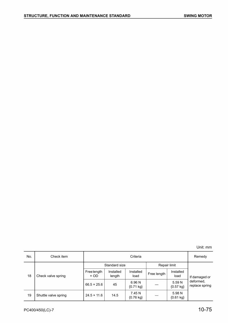
Unit: mm
No. Check item Criteria Remedy
18 Check valve spring
Standard size Repair limit
If damaged or deformed, replace spring
Free length × OD
Installed length
Installed load Free length Installed
load
66.5 × 25.6 45 6.96 N {0.71 kg} — 5.59 N
{0.57 kg}
19 Shuttle valve spring 24.5 × 11.6 14.5 7.45 N{0.76 kg} — 5.98 N
{0.61 kg}
PC400/450(LC)-7 10-75

STRUCTURE, FUNCTION AND MAINTENANCE STANDARD SWING MOTOR
RELIEF VALVE
1. OutlineThe relief portion consists of check valves (2)and (3), shuttle valves (4) and (5), and reliefvalve (1).
2. FunctionWhen the swing is stopped, the outlet port circuitof the motor from the control valve is closed, butthe motor continues to rotate under inertia, sothe pressure at the output side of the motorbecomes abnormally high, and this may dam-age the motor.To prevent this, the abnormally high pressure oilis relieved to port S from the outlet port of themotor (high-pressure side) to prevent any dam-age.
3. Operation1) When starting swing• When the swing control lever is operated to
swing right, the pressure oil from the pump pass-es through the control valve and is supplied toport MA. As a result, the pressure at port MA ris-es, the starting torque is generated in the motor,and the motor starts to rotate. The oil from theoutlet port of the motor passes from port MAthrough the control valve and returns to the tank.(Fig. 1)
2) When stopping swing• When the swing control lever is returned to neu-
tral, the supply of pressure oil from the pump toport MA is stopped. With the oil from the outletport of the motor, the return circuit to the tank isclosed by the control valve, so the pressure atport MB rises. As a result, rotation resistance isgenerated in the motor, so the braking effectstarts.
• If the pressure at port MB becomes higher thanthe pressure at port MA, it pushes shuttle valveA (4) and chamber C becomes the same pres-sure as port MB. The oil pressure rises furtheruntil it reaches the set pressure of relief valve (1).As a result, a high braking torque acts on the mo-tor and stops the motor. (Fig.2)
• When relief valve (1) is being actuated, the reliefoil and oil from port S passes through checkvalve B (3) and is supplied to port MA. This pre-vents cavitation at port MA.
10-76 PC400/450(LC)-7

STRUCTURE, FUNCTION AND MAINTENANCE STANDARD SWING MOTOR
Operation of swing lock1. When swing lock solenoid valve is deactivat-
edWhen the swing lock solenoid valve is deacti-vated, the pressurized oil from the main pump isshut off and port B is connected to the tank cir-cuit.As a result, brake piston (7) is pushed down bybrake spring (1), discs (5) and plates (6) arepushed together, and the brake is applied.
2. When swing lock solenoid valve is excitedWhen the swing lock solenoid valve is excited,the valve is switched and the pressure oil fromthe main pump enters port B and flows to brakechamber a.The pressure oil entering chamber a overcomesbrake spring (1) and pushes brake piston (7) up.As a result, discs (5) and plates (6) are sepa-rated and the brake is released.
PC400/450(LC)-7 10-77

STRUCTURE, FUNCTION AND MAINTENANCE STANDARD SWING MOTOR
REVERSAL PREVENTION VALVEOutline diagram
Explanation of effect
1. Valve body2. Spool (MA side)3. Spring (MA side)4. Plug5. Spool (MB side)6. Spring (MB side)7. Plug
10-78 PC400/450(LC)-7
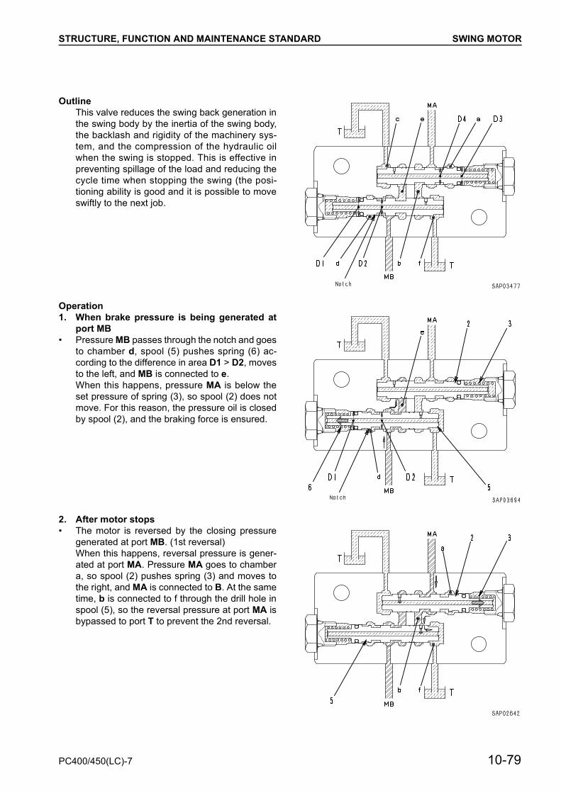
STRUCTURE, FUNCTION AND MAINTENANCE STANDARD SWING MOTOR
OutlineThis valve reduces the swing back generation inthe swing body by the inertia of the swing body,the backlash and rigidity of the machinery sys-tem, and the compression of the hydraulic oilwhen the swing is stopped. This is effective inpreventing spillage of the load and reducing thecycle time when stopping the swing (the posi-tioning ability is good and it is possible to moveswiftly to the next job.
Operation1. When brake pressure is being generated at
port MB• Pressure MB passes through the notch and goes
to chamber d, spool (5) pushes spring (6) ac-cording to the difference in area D1 > D2, movesto the left, and MB is connected to e.When this happens, pressure MA is below theset pressure of spring (3), so spool (2) does notmove. For this reason, the pressure oil is closedby spool (2), and the braking force is ensured.
2. After motor stops• The motor is reversed by the closing pressure
generated at port MB. (1st reversal)When this happens, reversal pressure is gener-ated at port MA. Pressure MA goes to chambera, so spool (2) pushes spring (3) and moves tothe right, and MA is connected to B. At the sametime, b is connected to f through the drill hole inspool (5), so the reversal pressure at port MA isbypassed to port T to prevent the 2nd reversal.
PC400/450(LC)-7 10-79

STRUCTURE, FUNCTION AND MAINTENANCE STANDARD CENTER SWIVEL JOINT
CENTER SWIVEL JOINT
Unit: mm
1. Cover A1 : To L.H. travel motor port PB T2 : To tank2. Body A2 : From control valve port A2 T1 : From L.H. and R.H. travel
motors port T3. Slipper seal C1 : To R.H. travel motor port PA4. O-ring B2 : From control valve port B2 D2 : From control valve port B55. Shaft D1 : To R.H. travel motor port PB B1 : To L.H. travel motor port PA
E : To L.H. and R.H. travel motors port P
C2 : From control valve port A5
No. Check item Criteria Remedy
6 Clearance between rotor and shaft
Standard Size Standard clearance Repair limit If damaged or deformed, replace spring80 — —
10-80 PC400/450(LC)-7


STRUCTURE, FUNCTION AND MAINTENANCE STANDARD TRAVEL MOTOR
TRAVEL MOTORKMV280ADT
Port T (to tank) SpecificationsPort PA (from control valve)Port PB (from control valve) Model: KMV200ADTPort PI (from travel speed solenoid valve) Theoretical delivery Min 130 cm3/rpm
Max 200 cm3/rpmBrake releasing pressure: 1.0 ± 0.4 MPa
{10 ± 4 kg/cm2}Travel speed switching pressure:
0.8 MPa {8 kg/cm2}(Differentical pressure)
+0.4–0.1
+4–1
10-82 PC400/450(LC)-7

STRUCTURE, FUNCTION AND MAINTENANCE STANDARD TRAVEL MOTOR
1. Output shaft 8. Regulator piston 15. Safety valve2. Motor case 9. Plate 16. Rgegulator valve3. Piston 10. Disc 17. Spring4. Cylinder 11. Check valve spring 18. Brake spring5. Valve plate 12. Check valve 19. Brake piston6. End cover 13. Counterbalance valve 20. Check valve7. Slow return valve 14. Spool return spring
PC400/450(LC)-7 10-83

STRUCTURE, FUNCTION AND MAINTENANCE STANDARD TRAVEL MOTOR
Unit: mm
No. Check item Criteria Remedy
21 Spool return spring
Standard size Repair limit
Replace spring if dam-aged or deformed
Free length × OD
Installed length
Installed load Free length Installed
load
62.52 × 32.0 42.0 426.6N {43.5 kg} — 341.3 N
{32.2 kg}
22 Check valve spring 62.5 × 20.0 39.0 3.04 N{0.31 kg} — 2.45 N
{0.25 kg}
23 Regulator piston spring 55.0× 9.0 50.0 98.1 N{10 kg} — 78.5 N
{8 kg}
10-84 PC400/450(LC)-7

STRUCTURE, FUNCTION AND MAINTENANCE STANDARD TRAVEL MOTOR
Operation of moter1) At low speed (motor swash plate angle at
maximumu)
• The solenoid valve is de-energized, so the pilotpressure oil from the main pump does not flow toport PFor this reason, regulator valve (16) is pusheddown by spring (17).
• The main pressure oil from the control valve push-es check valve (20), goes to end cover (6), in reg-ulator valve (16) and acts also on chamber b.
• When this happens, the propulsion force of reg-ulator piston (8) acts in a downward direction.
• As a result, valve plate (5) and cylinder block (4)move in the maximum swash plate angle direc-tion, the motor capacity becomes maximum, andthe system is set to low speed.
PC400/450(LC)-7 10-85
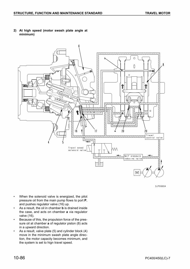
STRUCTURE, FUNCTION AND MAINTENANCE STANDARD TRAVEL MOTOR
2) At high speed (motor swash plate angle atminimum)
• When the solenoid valve is energized, the pilotpressure oil from the main pump flows to port P,and pushes regulator valve (16) up.
• As a result, the oil in chamber b is drained insidethe case, and acts on chamber a via regulatorvalve (16).
• Because of this, the propulsion force of the pres-sure oil at chamber a of regulator piston (8) actsin a upward direction.
• As a result, valve plate (5) and cylinder block (4)move in the minimum swash plate angle direc-tion, the motor capacity becomes minimum, andthe system is set to hign travel speed.
10-86 PC400/450(LC)-7
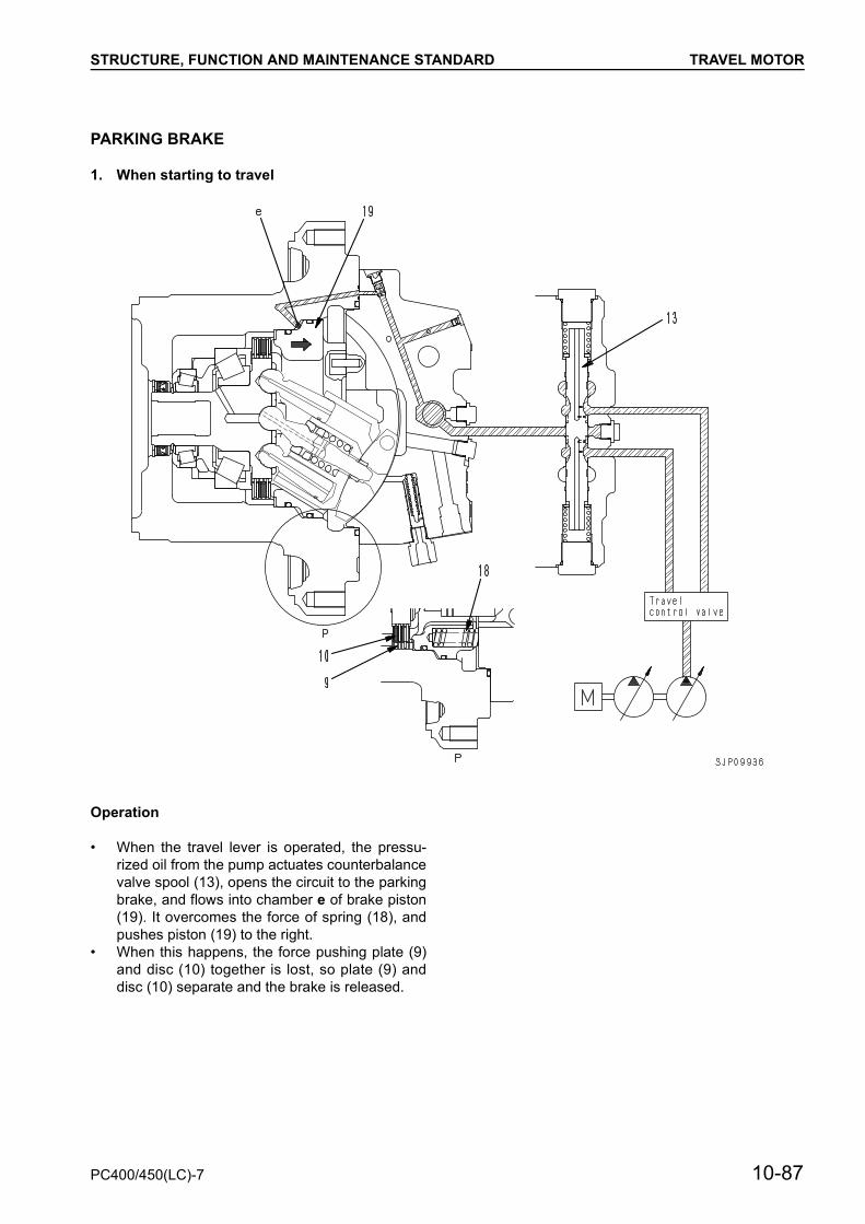
STRUCTURE, FUNCTION AND MAINTENANCE STANDARD TRAVEL MOTOR
PARKING BRAKE
1. When starting to travel
Operation
• When the travel lever is operated, the pressu-rized oil from the pump actuates counterbalancevalve spool (13), opens the circuit to the parkingbrake, and flows into chamber e of brake piston(19). It overcomes the force of spring (18), andpushes piston (19) to the right.
• When this happens, the force pushing plate (9)and disc (10) together is lost, so plate (9) anddisc (10) separate and the brake is released.
PC400/450(LC)-7 10-87

STRUCTURE, FUNCTION AND MAINTENANCE STANDARD TRAVEL MOTOR
2. When stopping travel
Operation
• When the travel lever is placed in neutral, coun-terbalance valve spool (13) returns to the neutralposition and the circuit to the parking brake isclosed.
• The pressurized oil in chamber e of brake piston(19) passes through the throttle of slow returnvalve (7) until spool (13) of the counterbalancevalve returns to neutral.
• When spool (13) of the counterbalance valve re-turns to the neutral position, the oil is drained in-side the case from the throttle f of brake piston(19) and brake piston (19) is pushed fully to theleft by spring (18).
• As a result, plate (9) and disc (10) are pushed to-gether, and the brake is applied.
• A time delay is provided by having the pressu-rized oil pass through a throttle in slow return
valve (7) when the brake piston returns, and thisensures that the brake is applied after the ma-chine stops.
10-88 PC400/450(LC)-7

STRUCTURE, FUNCTION AND MAINTENANCE STANDARD TRAVEL MOTOR
Operation of brake valve• The brake valve consists of a check valve (1),
counterbalance valve (2), and safety valve (3) ina circuit as shown in the diagram on the right.
• The function and operation of each component isas given below.
1) Counterbalance valve, check valve
Function• When traveling downhill, the weight of the ma-
chine makes it try to travel faster than the speedof the motor.As a result, if the machine travels with the engineat low speed, the motor will rotate without loadand the machine will run away, which is extreme-ly dangerous.To prevent this, these valves act to make the ma-chine travel according to the engine speed(pump discharge amount).
Operation when pressurized oil is supplied• When the travel lever is operated, the pressu-
rized oil from the control valve is supplied to portPA. It pushes open check valve (12a) and flowsfrom motor inlet port MA to motor outlet port MB.However, the motor outlet port is closed by checkvalve (12b) and spool (13), so the pressure at thesupply side rises.
PC400/450(LC)-7 10-89

STRUCTURE, FUNCTION AND MAINTENANCE STANDARD TRAVEL MOTOR
• The pressurized oil at the supply side flows fromorifice E1 in spool (13) and orifice E2 in the pis-ton to chamber S1. When the pressure in cham-ber S1 goes above the spool switching pressure,spool (13) is pushed to the right.As a result, port MB and port PB are connected,the outlet port side of the motor is opened, andthe motor starts to rotate.
Operation of brake when traveling downhill• If the machine tries to run away when traveling
downhill, the motor will turn under no load, so thepressure at the motor inlet port will drop, and thepressure in chamber S1 through orifices E1 andE2 will also drop.When the pressure in chamber S1 drops belowthe spool switching pressure, spool (13) is re-turned to the left by spring (14), and outlet portMB is throttled.As a result, the pressure at the outlet port siderises, resistance is generated to the rotation ofthe motor, and this prevents the machine fromrunning away.In other words, the spool moves to a positionwhere the pressure at outlet port MB balancesthe pressure at the inlet port and the force gener-ated by the weight of the machine. It throttles theoutlet port circuit and controls the travel speedaccording to the amount of oil discharged fromthe pump.
2) Safety valve (2-direction operation, 2-stageset safety valve)
Function• When travel is stopped (or when traveling down-
hill), the circuits at the inlet and outlet ports of themotor are closed by the counterbalance valve.However, the motor is totated by inertia, so thepressure at the outlet port of the motor will be-come abnormally high and will damage the motoror piping.The safety valve acts to release this abnormalpressure and send it to the inlet port side of themotor to prevent damage to the equipment.
10-90 PC400/450(LC)-7
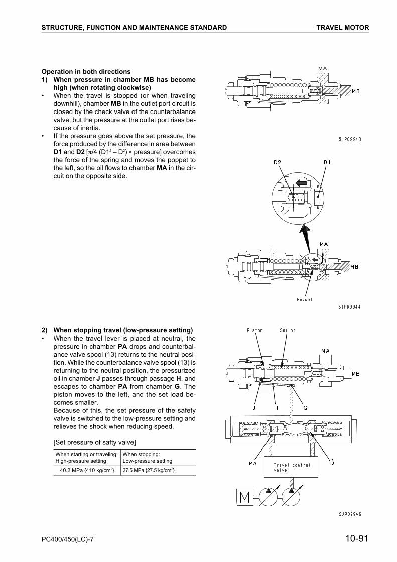
STRUCTURE, FUNCTION AND MAINTENANCE STANDARD TRAVEL MOTOR
Operation in both directions1) When pressure in chamber MB has become
high (when rotating clockwise)• When the travel is stopped (or when traveling
downhill), chamber MB in the outlet port circuit isclosed by the check valve of the counterbalancevalve, but the pressure at the outlet port rises be-cause of inertia.
• If the pressure goes above the set pressure, theforce produced by the difference in area betweenD1 and D2 [x/4 (D12 – D2) × pressure] overcomesthe force of the spring and moves the poppet tothe left, so the oil flows to chamber MA in the cir-cuit on the opposite side.
2) When stopping travel (low-pressure setting)• When the travel lever is placed at neutral, the
pressure in chamber PA drops and counterbal-ance valve spool (13) returns to the neutral posi-tion. While the counterbalance valve spool (13) isreturning to the neutral position, the pressurizedoil in chamber J passes through passage H, andescapes to chamber PA from chamber G. Thepiston moves to the left, and the set load be-comes smaller.Because of this, the set pressure of the safetyvalve is switched to the low-pressure setting andrelieves the shock when reducing speed.
[Set pressure of safty valve]When starting or traveling:High-pressure setting
When stopping:Low-pressure setting
40.2 MPa {410 kg/cm2} 27.5 MPa {27.5 kg/cm2}
PC400/450(LC)-7 10-91

STRUCTURE, FUNCTION AND MAINTENANCE STANDARD TRAVEL MOTOR
3) When pressure in chamber MA has becomehigh (when rotating counterclockwise)
• When the travel is stopped (or when travelingdownhill), chamber MA in the outlet port circuit isclosed by the check valve of the counterbalancevalve, but the pressure at the outlet port rises be-cause of inertia.
• If the pressure goes above the set pressure, theforce produced by the difference in area betweenD1 and D3 [x/4 (D32 – D12) × pressure] over-comes the force of the spring and moves thepoppet to the left, so the oil flows to chamber MBin the circuit on the opposite side.
Operation of mechanism for varying set pressure1) When starting travel (high-pressure setting)• When the travel lever is operated, the pressu-
rized oil from the pump actuates counterbalancevalve spool (19), and opens the pilot circuit to thesafety valve. The oil passes from chamber G topassage H and flows into chamber J, pushes thepiston to the right, and compresses the spring tomake the set load larger. Because of this, the setpressure of the safety valve is switched to thehigh pressure setting, and a large drawbar pull ismade available.
10-92 PC400/450(LC)-7

STRUCTURE, FUNCTION AND MAINTENANCE STANDARD TRAVEL JUNCTION VALVE
TRAVEL JUNCTION VALVEFunction• This valve connects both travel circuits to each
other so that the hydraulic oil will be suppliedevenly to both travel motors and the machine willtravel straight.
• When the machine is steered, outside pilot pres-sure PST closes the travel junction valve to se-cure high steering performance.
OperationWhen pilot pressure is turned ON• If the pilot pressure from the travel junction sole-
noid valve becomes higher than the force ofspring (14), travel junction spool (13) moves tothe left stroke end and the junction circuit be-tween port PTL (Left travel circuit) and PTR(Right travel circuit) is closed.
PC400/450(LC)-7 10-93
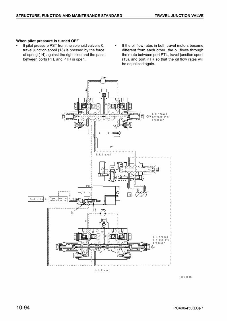
STRUCTURE, FUNCTION AND MAINTENANCE STANDARD TRAVEL JUNCTION VALVE
When pilot pressure is turned OFF• If pilot pressure PST from the solenoid valve is 0,
travel junction spool (13) is pressed by the forceof spring (14) against the right side and the passbetween ports PTL and PTR is open.
• If the oil flow rates in both travel motors becomedifferent from each other, the oil flows throughthe route between port PTL, travel junction spool(13), and port PTR so that the oil flow rates willbe equalized again.
10-94 PC400/450(LC)-7
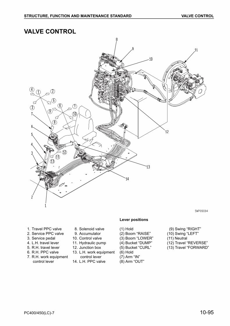
STRUCTURE, FUNCTION AND MAINTENANCE STANDARD VALVE CONTROL
VALVE CONTROL
Lever positions
1. Travel PPC valve 8. Solenoid valve (1) Hold (9) Swing “RIGHT”2. Service PPC valve 9. Accumulator (2) Boom “RAISE” (10) Swing “LEFT”3. Service pedal 10. Control valve (3) Boom “LOWER” (11) Neutral4. L.H. travel lever 11. Hydraulic pump (4) Bucket “DUMP” (12) Travel “REVERSE”5. R.H. travel lever 12. Junction box (5) Bucket “CURL” (13) Travel “FORWARD”6. R.H. PPC valve 13. L.H. work equipment
control lever(6) Hold
7. R.H. work equipment control lever
(7) Arm “IN”14. L.H. PPC valve (8) Arm “OUT”
PC400/450(LC)-7 10-95

STRUCTURE, FUNCTION AND MAINTENANCE STANDARD TRAVEL PPC SHUTTLE VALVE
TRAVEL PPC SHUTTLE VALVEFunction
• If boom RAISE or arm IN are operated when themachine is traveling, the stroke of the spools forthe boom and arm is controlled by the travel PPCpressure and this limits the flow of oil to the boomand arm cylinders.
• When the boom and arm stroke is controlled, thetravel PPC pressure passes through the circuitinside the control valve to actuate the system.
Operation
1. When travel is at neutral• Stroke limit signal chambers a and b are con-
nected to the travel PPC valve through orifices(5) and (6) in pistons (3) and (4) inside the travelspring case, and the is drained.
• When arm IN is operated, spool (1) moves to theright by stroke (st0) to a point where it contactsthe end face of spring case (2).
• When boom RAISE is operated, spool (9) movesto the left by stroke (st3) to a point where it con-tacts the end face of spring case (10).
10-96 PC400/450(LC)-7

STRUCTURE, FUNCTION AND MAINTENANCE STANDARD TRAVEL PPC SHUTTLE VALVE
PC400/450(LC)-7 10-97

STRUCTURE, FUNCTION AND MAINTENANCE STANDARD TRAVEL PPC SHUTTLE VALVE
2. When travel is operated• When the travel lever is operated to right RE-
VERSE (or FORWARD), the right (REVESE (orFORWARD) PPC pressure pushes spool (7) tothe left (or right).
• Spool (7) pushes piston (3), orifice (5) closes,and stroke limit signal chamber a is shut off fromthe drain circuit of the travel PPC valve.
• At the same time, the right REVERSE (or FOR-WARD) PPC pressure passes through orifice (6)in piston (4), acts on the right end face of piston(8), and pushes piston (8) to the left.
• If arm IN is operated, spool (1) moves to the right,but the maximum stroke of the spool is limited bythe amount of movement st2 of piston (8) andbecomes st1.
• If boom RAISE is operated, spool (9) tries tomove to the left, but the travel PPC pressure en-ters stroke control signal chamber b, so the spooldoes not move.
10-98 PC400/450(LC)-7
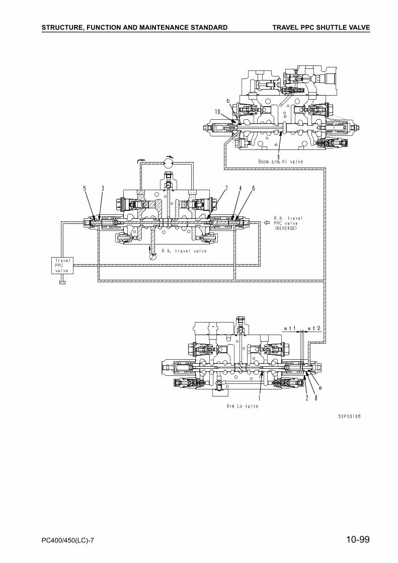
STRUCTURE, FUNCTION AND MAINTENANCE STANDARD TRAVEL PPC SHUTTLE VALVE
PC400/450(LC)-7 10-99

STRUCTURE, FUNCTION AND MAINTENANCE STANDARD WORK EQUIPMENT • SWING PPC VALVE
WORK EQUIPMENT • SWING PPC VALVE
P : From self pressure reducing valve P1 : Left PPC: Arm OUT / Right PPC: Boom LOWERT : To tank P2 : Left PPC: Arm IN / Right PPC: Boom RAISE
P3 : Left PPC: Swing LEFT / Right PPC: Bucket CURLP4 : Left PPC: Swing RIGHT / Right PPC: Boom LOWER
10-100 PC400/450(LC)-7
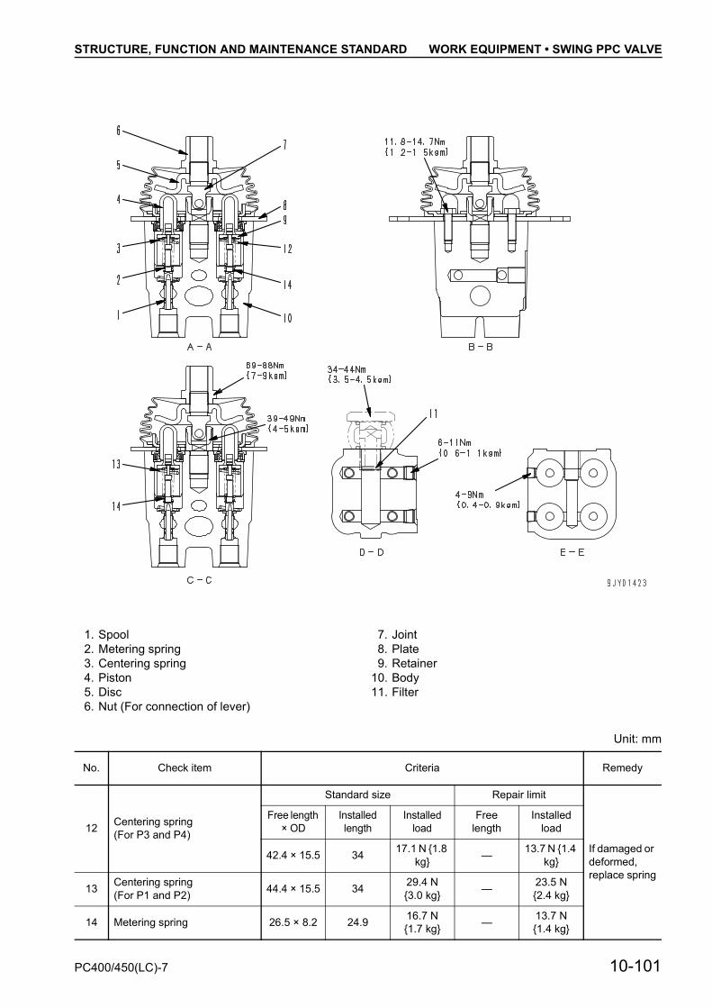
STRUCTURE, FUNCTION AND MAINTENANCE STANDARD WORK EQUIPMENT • SWING PPC VALVE
Unit: mm
1. Spool 7. Joint2. Metering spring 8. Plate3. Centering spring 9. Retainer4. Piston 10. Body5. Disc 11. Filter6. Nut (For connection of lever)
No. Check item Criteria Remedy
12 Centering spring(For P3 and P4)
Standard size Repair limit
If damaged or deformed, replace spring
Free length × OD
Installed length
Installed load
Free length
Installed load
42.4 × 15.5 34 17.1 N {1.8 kg} — 13.7 N {1.4
kg}
13 Centering spring(For P1 and P2) 44.4 × 15.5 34 29.4 N
{3.0 kg} — 23.5 N{2.4 kg}
14 Metering spring 26.5 × 8.2 24.9 16.7 N{1.7 kg} — 13.7 N
{1.4 kg}
PC400/450(LC)-7 10-101

STRUCTURE, FUNCTION AND MAINTENANCE STANDARD WORK EQUIPMENT • SWING PPC VALVE
Operation1) At neutral
Ports A and B of the control valve and ports P1and P2 of the PPC valve are connected to drainchamber D through fine control hole f in spool(1)
2) During fine control (neutral oooo fine control)When piston (4) starts to be pushed by disc (5),retainer (9) is pushed; spool (1) is also pushedby metering spring (2), and moves down.When this happens, fine control hole f is shut offfrom drain chamber D, and at almost the sametime, it is connected to pump pressure chamberPP, so pilot pressure oil from the main pumppasses through fine control hole f and goes fromport P1 to port A.When the pressure at port P1 becomes higher,spool (1) is pushed back and fine control hole fis shut off from pump pressure chamber PP. Atalmost the same time, it is connected to drainchamber D to release the pressure at port P1.When this happens, spool (1) moves up or downso that force of metering spring (2) is balancedwith the pressure at port P1. The relationship inthe position of spool (1) and body (10) (fine con-trol hole f is at a point midway between drainhole D and pump pressure chamber PP) doesnot change untill retainer (9) contacts spool (1).Therefore, metering spring (2) is compressedproportionally to the amount of movement of thecontrol lever, so the pressure at port P1 alsorises in proportion to the travel of the controllever. In this way, the control valve spool movesto position where the pressure in chamber A(the same as the pressure at port P1) and theforce of the control valve spool return spring arebalanced.
10-102 PC400/450(LC)-7

STRUCTURE, FUNCTION AND MAINTENANCE STANDARD WORK EQUIPMENT • SWING PPC VALVE
3) During fine control (when control lever isreturned)
• When disc (5) starts to be returned, spool (1) ispushed up by the force of centering spring (3)and the pressure at port P1.When this happens, fine control hole f is con-nected to drain chamber D and the pressure oilat port P1 is released.If the pressure at port P1 drops too far, spool (1)is pushed down by metering spring (2), and finecontrol hole f is shut off from drain chamber D.At almost the same time, it is connected topump pressure chamber PP, and the pumppressure is supplied until the pressure at port P1recovers to a pressure that corresponds to thelever position.When the spool of the control valve returns, oilin drain chamber D flows in from fine controlhole f’ in the valve on the side that is not work-ing. The oil passes through port P2 and enterschamber B to fill the chamber with oil.
4) At full strokeWhen disc (5) pushes down piston (4), andretainer (9) pushes down spool (1), fine controlhole f is shut off from drain chamber D, and isconnected with pump pressure chamber PP.Therefore, the pilot pressure oil from the mainpump passes through fine control hole f andflows to chamber A from port P1, and pushesthe control valve spool.The oil returning from chamber B passes fromport P2 through fine control hole f’ and flows todrain chamber D.
PC400/450(LC)-7 10-103

STRUCTURE, FUNCTION AND MAINTENANCE STANDARD TRAVEL PPC VALVE
TRAVEL PPC VALVE
P : From self pressure reducing valve P3 : Right reverseT : To tank P4 : Right forwardP1 : Left reverse P5 : Travel signalP2 : Left forward P6 : Steering signal
10-104 PC400/450(LC)-7

STRUCTURE, FUNCTION AND MAINTENANCE STANDARD TRAVEL PPC VALVE
1. Plate 6. Centering spring2. Body 7. Valve3. Piston 8. Damper4. Collar 9. Steering signal5. Metering spring 10. Steering signal valve spring
PC400/450(LC)-7 10-105

STRUCTURE, FUNCTION AND MAINTENANCE STANDARD TRAVEL PPC VALVE
Unit: mm
No. Check item Criteria Remedy
1 Metering spring
Standard size Repair limit
If damaged or deformed, replace spring
Free length × OD
Installed length
Installed load
Free length
Installed load
26.5 × 8.15 24.7 16.7 N {1.7 kg} — 13.7 N
{1.4 kg}
2 Centering spring 48.1 × 15.5 32.5 108 N{11 kg} — 86.3 N
{8.8 kg}
3 Steering signal spring 12.8 × 7.3 8.5 8.8 N{0.9 kg} — 7.1 N
{0.72 kg}
10-106 PC400/450(LC)-7

STRUCTURE, FUNCTION AND MAINTENANCE STANDARD TRAVEL PPC VALVE
Travel signal/Steering function
• Travel signalIf either of the travel levers is operated, the maximum PPC output pressure on both sides is output as thetravel signal. Accordingly, if the machine is traveling is judged by the signal of port P5.
• Steering signalIf the operation quantities of both levers are different from each other as in the steering operation, the higherone of the PPC output pressures on both sides is output as the steering signal.Any signal is not output from port P6 while the machine is travelling straight (forward or reverse) or in neu-tral.Accordingly, if the machine is being steered is judged by the signal of port P6.
Operation
1. While in NEUTRALThe signals of the output ports (P1 – P4), travel signal (Port P5), and steering signal (Port P6) are not out-put.
PC400/450(LC)-7 10-107

STRUCTURE, FUNCTION AND MAINTENANCE STANDARD TRAVEL PPC VALVE
2. While travelling straight(The following drawing shows the circuit for traveling straight forward.)While the left motor is operating for forward travel (the signal of port P2 is output) and the right motor is alsooperating for forward travel (the signal of port P4 is output), the pressures in left spring chamber (k) andright spring chamber (l) of steering signal valve (j) are set high. Accordingly, the steering signal valve is keptin neutral and the steering signal (Port P6) is not output.
10-108 PC400/450(LC)-7

STRUCTURE, FUNCTION AND MAINTENANCE STANDARD TRAVEL PPC VALVE
3. When steered or pivot-turned(The following drawing shows the circuit for left forward (slow) and right forward (fast) operation.)If the operation quantities of both levers are different from each other as in the steering operation (If the dif-ference of the pilot pressure between both sides is higher than a certain level), the pilot pressure is outputas the steering signal.In the case of the following drawing, the pressure in left spring chamber (k) of steering signal valve (j) is P2.The pressure in right spring chamber (l) is P4.If (P4 – P2) × (Sectional area of spool) > Set spring load, the spool is changed to the direction of the arrowand the higher one of both PPC output pressures (the pressure of port P4 in this drawing) is output as thesteering signal to port P6.
PC400/450(LC)-7 10-109
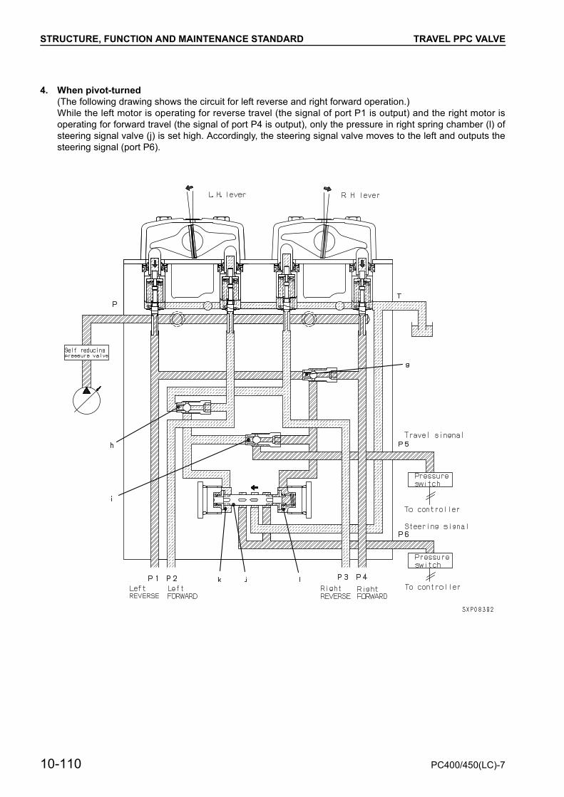
STRUCTURE, FUNCTION AND MAINTENANCE STANDARD TRAVEL PPC VALVE
4. When pivot-turned(The following drawing shows the circuit for left reverse and right forward operation.)While the left motor is operating for reverse travel (the signal of port P1 is output) and the right motor isoperating for forward travel (the signal of port P4 is output), only the pressure in right spring chamber (l) ofsteering signal valve (j) is set high. Accordingly, the steering signal valve moves to the left and outputs thesteering signal (port P6).
10-110 PC400/450(LC)-7

STRUCTURE, FUNCTION AND MAINTENANCE STANDARD SERVICE PPC VALVE
SERVICE PPC VALVEa Refer to the section WORK EQUIPMENT •
SWING PPC VALVE for function of this valve.
Unit: mm
No. Check item Criteria Remedy
9 Centering spring
Standard size Repair limit
If damaged or deformed, replace spring
Free length× OD
Installedlength
Installedload
Free length
Installed load
33.9 × 15.3 28.4 124.5 N{12.7 kg} — 100 N
{10.2 kg}
10 Metering spring 22.7 × 8.1 22 16.7 N{1.7 kg} — 13.7 N
{1.4 kg}
1. Spool2. Metering spring3. Centering spring4. Piston5. Lever6. Plate7. Retainer8. Body
T : To tankP : From main pumpP1 : PortP2 : Port
PC400/450(LC)-7 10-111

STRUCTURE, FUNCTION AND MAINTENANCE STANDARD SOLENOID VALVE
SOLENOID VALVEPPC lock, 2-stage relief, travel speed, swing brake, merge-divider, machine push-up, travel junction solenoidvalves
1. PPC lock solenoid valve T : To tank A8 : To main valve (2-stage reliefvalve)2. Travel junction solenoid valve A1 : To No. 1 pump (CO valve)
3. Merge-divider solenoid valve A2 : To main valve (Travel junc-tion valve)
P1 : From main pump4. Travel speed solenoid valve ACC : To accumulator5. Swing brake solenoid valve A3 : To main valve (Merge-divider
valve)6. Machine push-up solenoid valve8. 2-stage relief solenoid valve A4 : To both travel motors
A5 : To swing motorA6 : To 2-stage safety valve at
boom cylinder head
10-112 PC400/450(LC)-7

STRUCTURE, FUNCTION AND MAINTENANCE STANDARD SOLENOID VALVE
Operation
WHEN SOLENOID IS TURNED OFF
• Since the signal current does not flow from thecontroller, solenoid (3) is turned off.Accordingly, spool (4) is pressed by spring (6)against the left side.By this operation, the pass from P to A is closedand the hydraulic oil from the main pump doesnot flow into the actuator.At this time, the oil from the actuator is drainedthrough ports A and T into the tank.
WHEN SOLENOID IS TURNED ON
• The signal current flows from the controller to so-lenoid (3), and the latter is turned on.Accordingly, spool (4) is pressed against to theright side.By this operation, the hydraulic oil from the mainpump flows through port P and spool (4) to portA, then flows into the actuator.At this time, port T is closed and the oil does notflow into the tank.
1. Connector2. Moving core3. Coil4. Spool5. Block6. Spring
PC400/450(LC)-7 10-113

STRUCTURE, FUNCTION AND MAINTENANCE STANDARD PPC ACCUMULATOR
PPC ACCUMULATOR
1
2
3
4
5
6
SBP00290
1. Gas plug2. Shell3. Poppet4. Holder5. Bladder6. Oil port
SpecificationsGas capacity: 300 cc (for PPC)
10-114 PC400/450(LC)-7
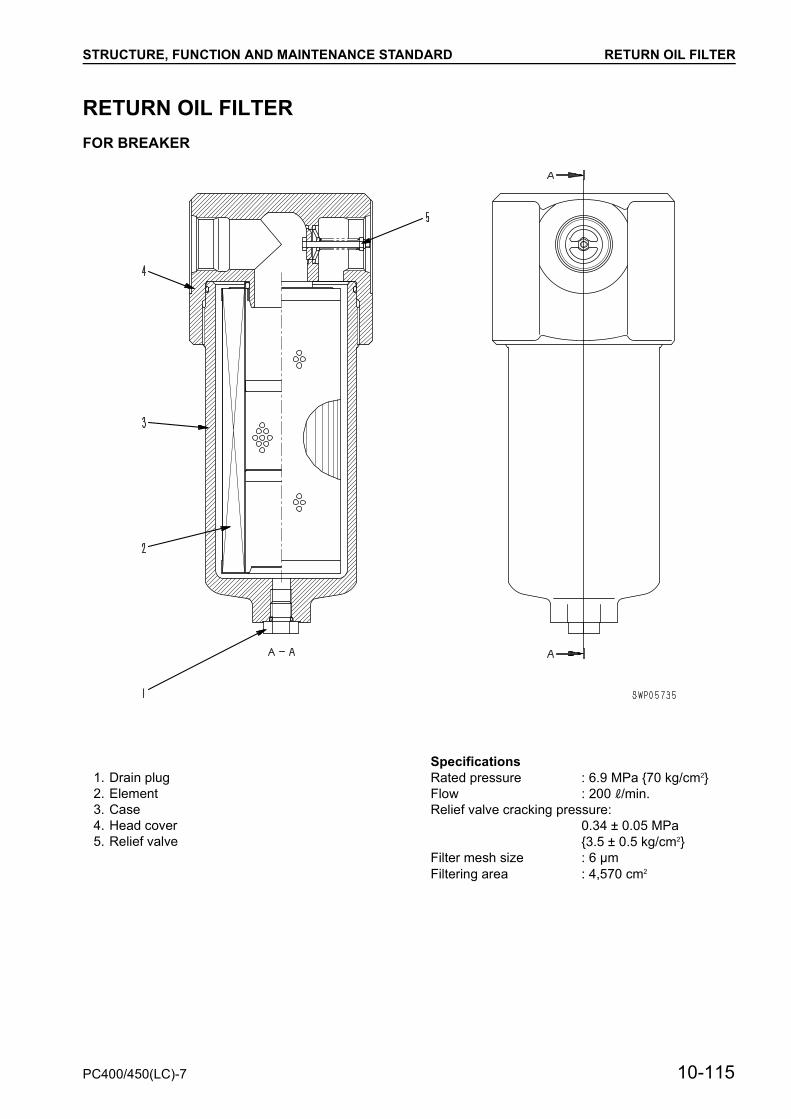
STRUCTURE, FUNCTION AND MAINTENANCE STANDARD RETURN OIL FILTER
RETURN OIL FILTERFOR BREAKER
Specifications1. Drain plug Rated pressure : 6.9 MPa {70 kg/cm2}
Flow : 200 l/min.Relief valve cracking pressure:
0.34 ± 0.05 MPa{3.5 ± 0.5 kg/cm2}
Filter mesh size : 6 µmFiltering area : 4,570 cm2
2. Element3. Case4. Head cover5. Relief valve
PC400/450(LC)-7 10-115
STRUCTURE, FUNCTION AND MAINTENANCE STANDARD BOOM HYDRAULIC DRIFT PREVENTION
BOOM HYDRAULIC DRIFT PREVENTION VALVEFunction
• When the boom lever is not being operated,these valves act to prevent the oil at the boombottom from leaking from spool (1) and preventthe boom from moving down.
Operation
1. Boom RAISEWhen the boom RAISE is operated, the mainpressure oil acts in the left direction on ring-shaped area A (= Area of ød1 – Area of ød2)because of the difference in the outside diame-ter d1 of poppet (5) and seat diameter d2. Whenit overcomes the force of spring (4), poppet (5)moves to the left.In addition, the main pressure oil acts in the rightdirection on seat diameter d3 of valve (6). Whenit overcomes the force of spring (4), valve (6)moves to the right.As a result, the main pressure oil prom the con-trol valve passes through the opening of poppet(5) and flows to the bottom end of the boom cyl-inder.
10-116 PC400/450(LC)-7

STRUCTURE, FUNCTION AND MAINTENANCE STANDARD BOOM HYDRAULIC DRIFT PREVENTION
PC400/450(LC)-7 10-117
STRUCTURE, FUNCTION AND MAINTENANCE STANDARD BOOM HYDRAULIC DRIFT PREVENTION
2. Boom at HOLD• When the boom is raised and the control lever is
returned to the HOLD position, the oil that hasflowed into the inside of poppet (5) through ori-fice a in poppet (5) is closed by pilot piston (2).The main pressure oil and hold pressure at thebottom of the boom cylinder are shut off.
• At the same time, the hold pressure at the bottomend of the boom cylinder acts in the right direc-tion on ring-shaped area A (= Area of ød1 – Areaof ød2) because of the difference in the outsidediameter d1 of poppet (5) and seat diameter d2.Poppet (5) is closed by the total of this force andthe force of spring (4), so the main pressure oiland hold pressure at the bottom of the boom cyl-inder are shut off.
• In addition, the hold pressure at the bottom of theboom cylinder acts in the left direction on outsidediameter d4 of valve (6).
• Valve (6) is closed by the total of this force andthe force of spring (4), so the main pressure oiland hold pressure at the bottom of the boom cyl-inder are shut off. As a result, the boom is held inposition.
10-118 PC400/450(LC)-7

STRUCTURE, FUNCTION AND MAINTENANCE STANDARD BOOM HYDRAULIC DRIFT PREVENTION
PC400/450(LC)-7 10-119

STRUCTURE, FUNCTION AND MAINTENANCE STANDARD BOOM HYDRAULIC DRIFT PREVENTION
3. Boom LOWER• When boom LOWER is operated, the pilot pres-
sure from the PPC valve pushes pilot spool (2),and the pressure oil chamber b inside the poppetis drained through orifice c.The oil at the bottom end of the boom flows fromorifice a to chamber b to orifice c to drain, so theoil pressure in chamber b drops.When the pressure in chamber b drops belowthe pressure at port b, poppet (4) opens, andthe pressure oil from port B goes to port A andflows to the control valve.
10-120 PC400/450(LC)-7
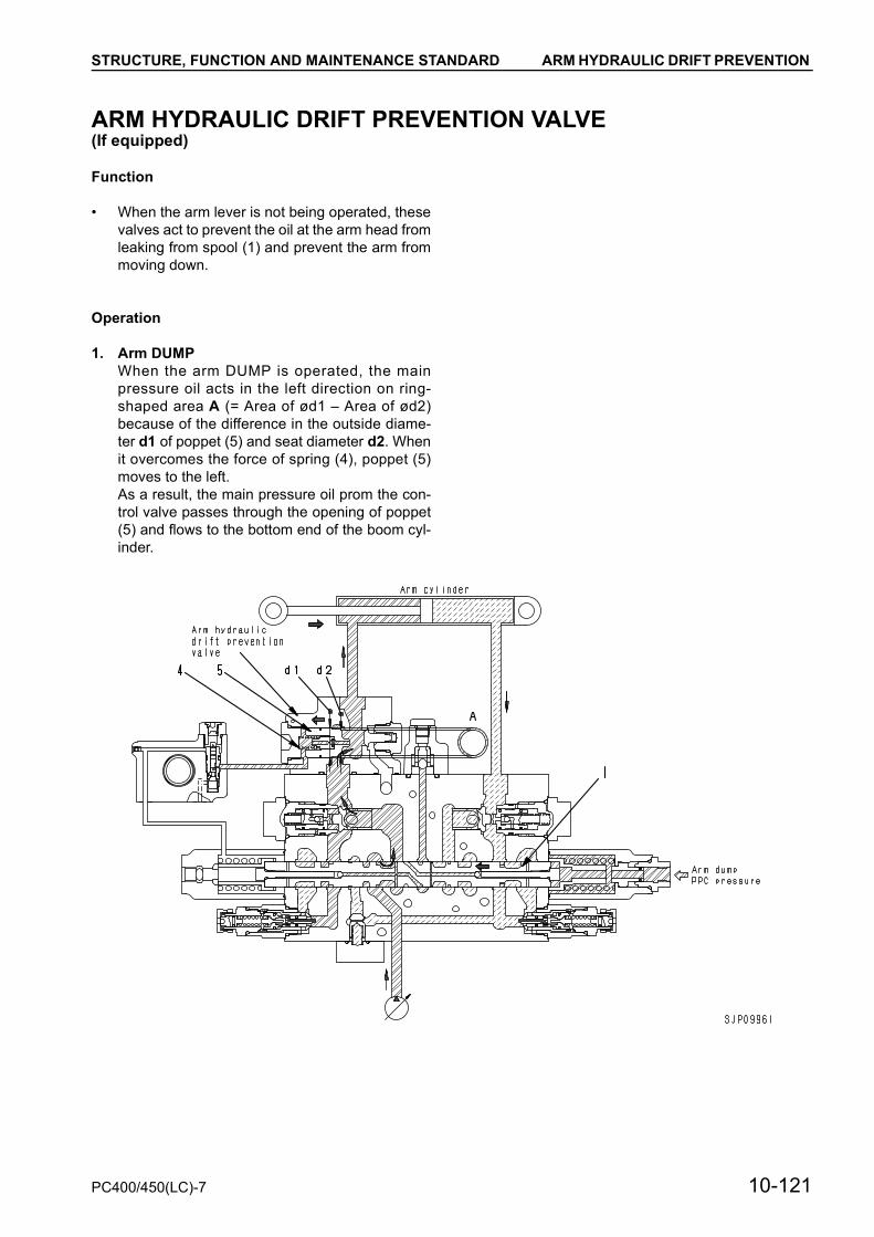
STRUCTURE, FUNCTION AND MAINTENANCE STANDARD ARM HYDRAULIC DRIFT PREVENTION
ARM HYDRAULIC DRIFT PREVENTION VALVE(If equipped)
Function
• When the arm lever is not being operated, thesevalves act to prevent the oil at the arm head fromleaking from spool (1) and prevent the arm frommoving down.
Operation
1. Arm DUMPWhen the arm DUMP is operated, the mainpressure oil acts in the left direction on ring-shaped area A (= Area of ød1 – Area of ød2)because of the difference in the outside diame-ter d1 of poppet (5) and seat diameter d2. Whenit overcomes the force of spring (4), poppet (5)moves to the left.As a result, the main pressure oil prom the con-trol valve passes through the opening of poppet(5) and flows to the bottom end of the boom cyl-inder.
PC400/450(LC)-7 10-121

STRUCTURE, FUNCTION AND MAINTENANCE STANDARD ARM HYDRAULIC DRIFT PREVENTION
2. Arm at HOLD• When the arm DUMP is operated and the control
lever is returned to the HOLD position, the oil thathas flowed into the inside of poppet (5) throughorifice a in poppet (5) is closed by pilot piston (2).The main pressure oil and hold pressure at thehead of the arm cylinder are shut off.
• At the same time, the hold pressure at the bottomend of the boom cylinder acts in the right direc-tion on ring-shaped area A (= Area of ød1 – Areaof ød2) because of the difference in the outsidediameter d1 of poppet (5) and seat diameter d2.Poppet (5) is closed by the total of this force andthe force of spring (4), so the main pressure oiland hold pressure at the head of the arm cylinderare shut off.
• In addition, the hold pressure at the bottom of theboom cylinder acts in the left direction on outsidediameter d4 of valve (6).As a result, the arm is held in position.
10-122 PC400/450(LC)-7
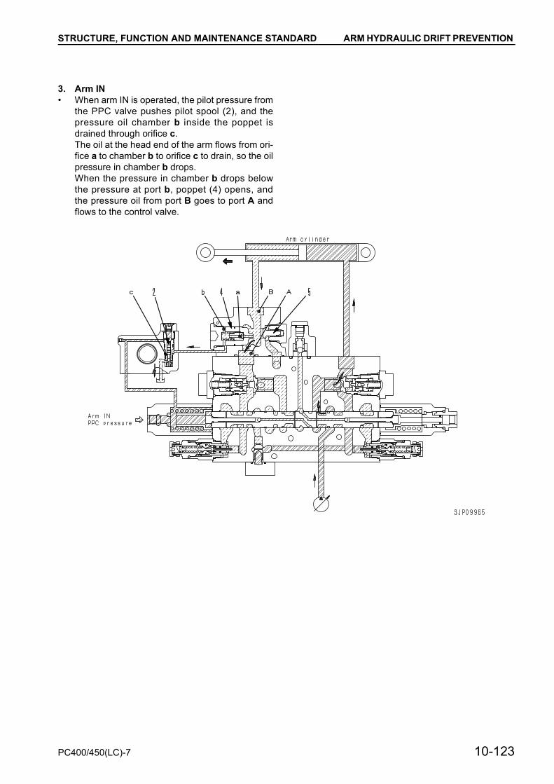
STRUCTURE, FUNCTION AND MAINTENANCE STANDARD ARM HYDRAULIC DRIFT PREVENTION
3. Arm IN• When arm IN is operated, the pilot pressure from
the PPC valve pushes pilot spool (2), and thepressure oil chamber b inside the poppet isdrained through orifice c.The oil at the head end of the arm flows from ori-fice a to chamber b to orifice c to drain, so the oilpressure in chamber b drops.When the pressure in chamber b drops belowthe pressure at port b, poppet (4) opens, andthe pressure oil from port B goes to port A andflows to the control valve.
PC400/450(LC)-7 10-123

STRUCTURE, FUNCTION AND MAINTENANCE STANDARD ARM HYDRAULIC DRIFT PREVENTION
4. When abnormally high pressure is generated
• If abnormally high pressure is generated in theboom cylinder bottom circuit, the hydraulic oil inport B pushes check valve (6) open, then safetyvalve (3) operates.
• If the hydraulic drift prevention valve for the armcylinder head circuit is installed (optional), thehydraulic oil in the boom cylinder bottom circuitor that in the arm cylinder head circuit, havinghigher pressure, pushes check valve (6) open,then safety valve (3) operates.
10-124 PC400/450(LC)-7

STRUCTURE, FUNCTION AND MAINTENANCE STANDARD QUICK RETURN VALVE
QUICK RETURN VALVEFunction
When arm OUT is operated, this valve reduces thepressure loss of the large amount of oil returningfrom the cylinder bottom.
Operation
1. Arm at OUTWhen arm OUT is operated, the pilot pressurefrom the PPC valve pushes pilot spool (1), andthe pressure oil from chamber b inside the pop-pet is drained through orifice c.The oil at the bottom end of the arm flows fromorifice a to chamber b to orifice c to drain, so theoil pressure in chamber b drops.When the pressure in chamber b drops below thepressure at port A, the pressure at port A andacts on ring -shaped area C (= Area of ød1 –Area of ød2) because of the difference in the out-side diameter d1 of valve (2) and seat diameterd2. Valve (2) moves to the left and the pressureoil from port A goes to port B. From port B, the oilis drained directly to the tank.
PC400/450(LC)-7 10-125

STRUCTURE, FUNCTION AND MAINTENANCE STANDARD QUICK RETURN VALVE
2. Arm at HOLDThe oil that has flowed through orifice a in valve(2) is closed by pilot piston (1). At the sametime, the hold pressure at the bottom end of thearm acts in the right direction on ring-shapedarea C (= Area of ød1 – Area of ød2) becauseof the difference in the outside diameter d1 ofvalve (2) and seat diameter d2. Valve (2) isclosed by the total of this force and the force ofspring (3), so port A and port B are shut off.
10-126 PC400/450(LC)-7

STRUCTURE, FUNCTION AND MAINTENANCE STANDARD LIFT CHECK VALVE
LIFT CHECK VALVEFunction
This valve applies back pressure to the drain circuitto prevent generation of negative pressure on thehydraulic devices for the work equipment (motors,cylinders, etc.)
Operation
1. While engine is stoppedAny oil is not supplied from the pump to the self-pressure reducing valve and valve (1) is pressedby only the force of spring (2) toward the rightand drain circuit “a” of the control valve is con-nected through orifice “b” of valve (1) to port T.
2. While engine is running• Output pressure PR of the self-pressure reduc-
ing valve is applied through the control valve tospring chamber “c” of the back pressure valve.
• Output pressure PR applied to spring chamber“c” is applied to the left end of valve (1) (area ofød) to push valve (1) to the right.
• At this time, pressure PA of drain circuit “a” of thecontrol valve is applied to the right end of valve(1) (area of ød1) to push valve (1) to the left.
• Valve (1) is balanced so that the back pressurePA will be as follows.PA = {(Area of ød) × PR + Force of spring (2)} /(Area of ød1)
PC400/450(LC)-7 10-127

STRUCTURE, FUNCTION AND MAINTENANCE STANDARD ATTACHMENT CIRCUIT SELECTOR VALVE
ATTACHMENT CIRCUIT SELECTOR VALVE
Unit: mm
1. Spool V : To control valve2. Spring T : To hydraulic tank
ATT : To attachmentACC: To accumulatorP1 : From attachment circuit selector solenoid valveTS : To hydraulic tank
No. Check item Criteria Remedy
3 Spool return spring
Standard size Repair limit Replace spring if any damages or deformations are found
Free length × OD
Installedlength
Installedload
Free length
Installed load
132.0 × 29 114.5 833 N{85.0 kg} — 666 N
{68.0 kg}
10-128 PC400/450(LC)-7

STRUCTURE, FUNCTION AND MAINTENANCE STANDARD ATTACHMENT CIRCUIT SELECTOR VALVE
Function
When a breaker is installed, the return oil from thebreaker does not pass through the main valve, butreturns directly to the hydraulic tank. When otherattachments (crusher, etc.) are installed, the attach-ment and the main valve are interconnected.
Operation
1. When attachment other than breaker is in-stalledSpool (1) is pushed fully to the left by the forceof spring (2), ATT port and port V are intercon-nected, and ATT port and port T are shut off, sothe attachment and main valve are intercon-nected.
2. When breaker is installedWhen the pilot pressure from the attachment cir-cuit selector solenoid valve overcomes the forceof spring (2), the spool (1) moves fully to theright. ATT port and port V are shut off and ATTport and port T are interconnected, so the oilreturning from the breaker does not passthrough the main valve, but passes through portT and returns directly to the hydraulic tank.
PC400/450(LC)-7 10-129

STRUCTURE, FUNCTION AND MAINTENANCE STANDARD HOLDING VALVE
HOLDING VALVEDownward movement prevention valve(For boom and arm)
V : From control valveT : To hydraulic tankCY : To hydraulic cylinderPI : From PPC valvePCY : Fror pressure pickup and equalizer circuits
10-130 PC400/450(LC)-7

STRUCTURE, FUNCTION AND MAINTENANCE STANDARD HOLDING VALVE
Unit: mm
No. Check item Criteria Remedy
7 Check valve spring
Standard size Repair limit
If damaged of deformed, replace spring
Free length × OD
Installedlength
Installedload
Free length
Installed load
20.8 × 12.2 13.5 12.7 N{1.3 kg} — 9.8 N
{1.0 kg}
8 Spool return spring 41.1 × 9.6 35 58.8 N{6.0 kg} — 47.0 N
{4.8 kg}
9 Spool return spring 41.9 × 25.8 41 78.4 N{8.0 kg} — 62.7 N
{6.4 kg}
10 Spool return spring 43.2 × 25.4 41 125.4 N{12.8 kg} — 100.4 N
{10.2 kg}
1. Pilot spool2. Spring (1st stage of spool)3. Spring (2nd stage of spool)4. Safety valve5. Check valve6. Spring
PC400/450(LC)-7 10-131
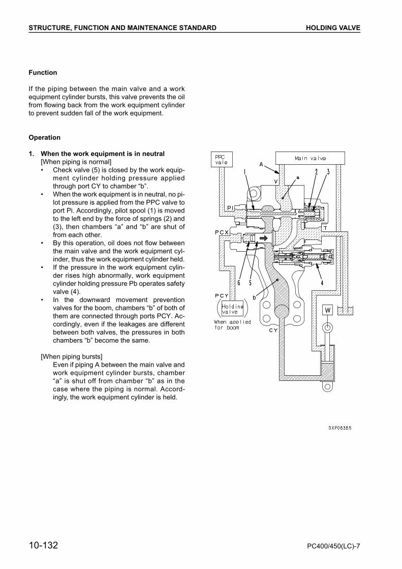
STRUCTURE, FUNCTION AND MAINTENANCE STANDARD HOLDING VALVE
Function
If the piping between the main valve and a workequipment cylinder bursts, this valve prevents the oilfrom flowing back from the work equipment cylinderto prevent sudden fall of the work equipment.
Operation
1. When the work equipment is in neutral[When piping is normal]• Check valve (5) is closed by the work equip-
ment cylinder holding pressure appliedthrough port CY to chamber “b”.
• When the work equipment is in neutral, no pi-lot pressure is applied from the PPC valve toport Pi. Accordingly, pilot spool (1) is movedto the left end by the force of springs (2) and(3), then chambers “a” and “b” are shut offrom each other.
• By this operation, oil does not flow betweenthe main valve and the work equipment cyl-inder, thus the work equipment cylinder held.
• If the pressure in the work equipment cylin-der rises high abnormally, work equipmentcylinder holding pressure Pb operates safetyvalve (4).
• In the downward movement preventionvalves for the boom, chambers “b” of both ofthem are connected through ports PCY. Ac-cordingly, even if the leakages are differentbetween both valves, the pressures in bothchambers “b” become the same.
[When piping bursts]Even if piping A between the main valve andwork equipment cylinder bursts, chamber“a” is shut off from chamber “b” as in thecase where the piping is normal. Accord-ingly, the work equipment cylinder is held.
10-132 PC400/450(LC)-7

STRUCTURE, FUNCTION AND MAINTENANCE STANDARD HOLDING VALVE
2. When oil is sent from main valve to cylinder[When piping is normal]• If pressure Pa of the oil sent from the main
valve to chamber “a” is higher thanthe total ofpressure Pb in chamber “b” connected to thework equipment cylinder and the force ofspring (6), check valve (5) opens and cham-bers and the oil flows from the main valve tothe work equipment cylinder.
[When piping bursts]• If piping A between the main valve and the
work equipment cylinder bursts, the oil inchamber “a” flows out through the burst partand pressure Pa in chamber “a” lowers.
• If Pa lowers below the total of pressure Pb inchamber “b” and the force of spring (6),check valve (5) closes and chambers “a” and“b” are shut off from each other. Accordingly,pressure Pb in the cylinder is held and thework equipment does not fall suddenly.
PC400/450(LC)-7 10-133
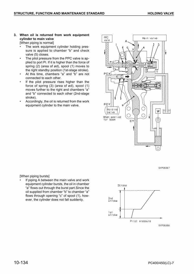
STRUCTURE, FUNCTION AND MAINTENANCE STANDARD HOLDING VALVE
3. When oil is returned from work equipmentcylinder to main valve[When piping is normal]• The work equipment cylinder holding pres-
sure is applied to chamber “b” and checkvalve (5) closes.
• The pilot pressure from the PPC valve is ap-plied to port Pi. If it is higher than the force ofspring (2) (area of ød), spool (1) moves tothe right standby position (1st-stage stroke).
• At this time, chambers “a” and “b” are notconnected to each other.
• If the pilot pressure rises higher than theforce of spring (3) (area of ød), spool (1)moves further to the right and chambers “a”and “b” connected to each other (2nd-stagestroke).
• Accordingly, the oil is returned from the workequipment cylinder to the main valve.
[When piping bursts]• If piping A between the main valve and work
equipment cylinder bursts, the oil in chamber“a” flows out through the burst part.Since theoil supplied from chamber “b” to chamber “a”flows through opening “c” of spool (1), how-ever, the cylinder does not fall suddenly.
10-134 PC400/450(LC)-7


STRUCTURE, FUNCTION AND MAINTENANCE STANDARD HYDRAULIC CYLINDER
HYDRAULIC CYLINDERBOOM CYLINDER
ARM CYLINDER
BUCKET CYLINDER
10-136 PC400/450(LC)-7
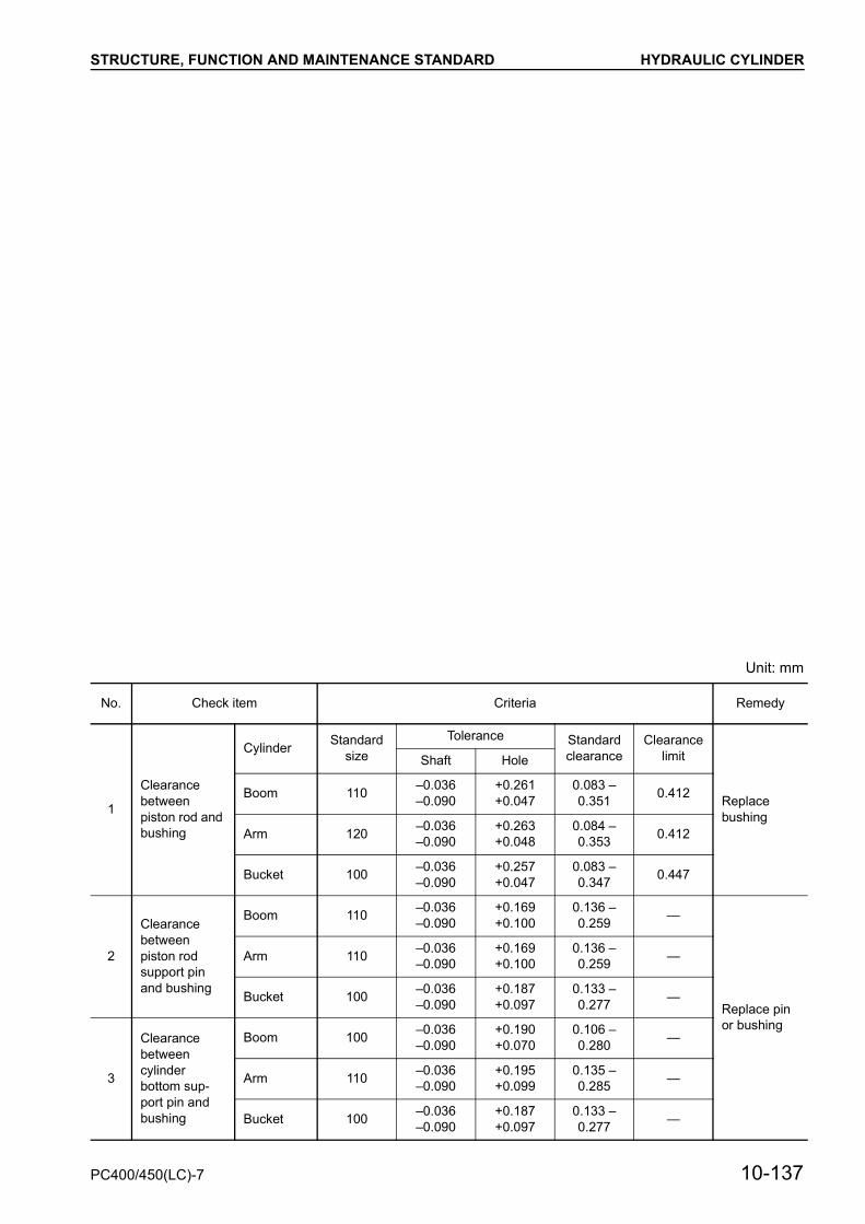
STRUCTURE, FUNCTION AND MAINTENANCE STANDARD HYDRAULIC CYLINDER
Unit: mm
No. Check item Criteria Remedy
1
Clearance between piston rod and bushing
Cylinder Standard size
Tolerance Standard clearance
Clearancelimit
Replace bushing
Shaft Hole
Boom 110 –0.036–0.090
+0.261+0.047
0.083 – 0.351 0.412
Arm 120 –0.036–0.090
+0.263+0.048
0.084 – 0.353 0.412
Bucket 100 –0.036–0.090
+0.257+0.047
0.083 – 0.347 0.447
2
Clearance between piston rod support pin and bushing
Boom 110 –0.036–0.090
+0.169+0.100
0.136 – 0.259 —
Replace pin or bushing
Arm 110 –0.036–0.090
+0.169+0.100
0.136 – 0.259 —
Bucket 100 –0.036–0.090
+0.187+0.097
0.133 – 0.277 —
3
Clearance between cylinder bottom sup-port pin and bushing
Boom 100 –0.036–0.090
+0.190+0.070
0.106 – 0.280 —
Arm 110 –0.036–0.090
+0.195+0.099
0.135 – 0.285 —
Bucket 100 –0.036–0.090
+0.187+0.097
0.133 – 0.277 —
PC400/450(LC)-7 10-137

STRUCTURE, FUNCTION AND MAINTENANCE STANDARD WORK EQUIPMENT
WORK EQUIPMENT
10-138 PC400/450(LC)-7

STRUCTURE, FUNCTION AND MAINTENANCE STANDARD WORK EQUIPMENT
Unit: mm
No. Check item Criteria Remedy
1Clearance between connecting pin and bushing of revolving frame and boom
Standard size
Tolerance Standard clearance
Clearancelimit
Replace
Shaft Hole
120 –0.036–0.090
+0.173+0.101
0.137 – 0.263 1.0
2Clearance between connecting pin and bushing of boom and arm
120 –0.036–0.090
+0.180+0.112
0.148 – 0.270 1.0
3Clearance between connecting pin and bushing of arm and link
100 –0.036–0.090
+0.172+0.081
0.117 – 0.262 1.0
4Clearance between connect-ing pin and bushing of arm and bucket
100 –0.036–0.090
+0.138+0.077
0.113 – 0.228 1.0
5Clearance between connect-ing pin and bushing of link and bucket
100 –0.036–0.090
+0.172+0.081
0.117 – 0.262 1.0
6Clearance between connect-ing pin and bushing of link and link
100 –0.036–0.090
+0.190+0.097
0.133 – 0.280 1.0
7 Bucket clearance (a) 0.5 – 1.0Adjust shims
8 Bucket clearance (b) 2.0
PC400/450(LC)-7 10-139

STRUCTURE, FUNCTION AND MAINTENANCE STANDARD WORK EQUIPMENT
1. Dimension of arm
10-140 PC400/450(LC)-7

STRUCTURE, FUNCTION AND MAINTENANCE STANDARD WORK EQUIPMENT
Unit: mm
Model
No.PC400-7 PC450-7
1 ø110 / ø110 /
2 ø129.3 / 126 ± 1.2 ø129.3 / 126 ± 1.2
3 ø355 / 351 ø355 / 351
4 ø120 / ø120 /
5 514.8 570.6
6 195 208.2
7 1,038 1,132.2
8 3,375 3,375
9 2,977.5 2,975.1
10 502 506.8
11 720 720
12 719 719
13 537.1 537.1
14 1,850 1,817
15 ø100 / ø100 /
16 ø371 / 370 ± 0.5 ø371 / 370 ± 0.5
17 ø100 / ø100 /
18
Arm as individual part 355 355
When press-fitting bushing 370 370
19Min. 1,870 1,870
Max. 3,140 3,140
+0.1+0
–0.036–0.090
+0.1+0
–0.036–0.090
+1.5+0
+1.5+0
+0.5+0
–0.3–0.8
+0.5+0
–0.3–0.8
+0.1+0
–0.036–0.090
+0.1+0
–0.036–0.090
+0.1+0
–0.036–0.090
+0.1+0
–0.036–0.090
+1+0
+1+0
+0.1+0
–0.036–0.090
+0.1+0
–0.036–0.090
–0–0.5
–0–0.5
PC400/450(LC)-7 10-141
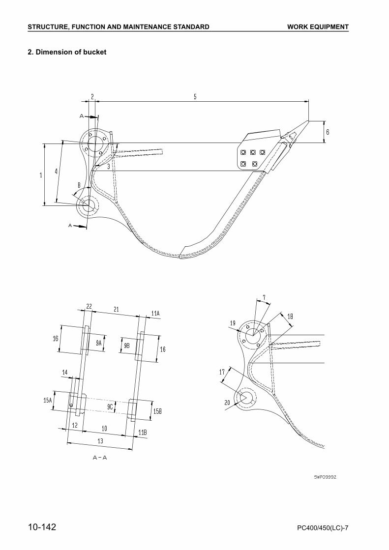
STRUCTURE, FUNCTION AND MAINTENANCE STANDARD WORK EQUIPMENT
2. Dimension of bucket
10-142 PC400/450(LC)-7

STRUCTURE, FUNCTION AND MAINTENANCE STANDARD WORK EQUIPMENT
Unit: mm
Model
No.PC400-7 PC450-7
1 534.1 ± 0.5 534.1 ± 0.5
2 56.3 ± 0.5 56.3 ± 0.5
3 96° 1’ 94° 14’
4 537.1 537.1
5 1,839 1,806
6 190 198
7 — —
8 62° 1’ 46° 1’
9
A ø140.1 ± 8.1 ø140.1 ± 8.1
B ø130 ø130
C ø100 ø100
10 371 371
11A 57 50
B 72 72
12 144 144
13 562.5 562.5
14 ø26 ø26
15A ø165 ø165
B — —
16 ø230 ø230
17 146.1 135.5
18 137.6 142.0
19 R115 R115
20 R85 R85
21 410 ± 1 410 ± 1
22 64 64
+0.063–0
+0.063–0
+0.1+0
+0.1+0
+1+0
+1+0
+0.5–2.5
+0.5–2.5
PC400/450(LC)-7 10-143

STRUCTURE, FUNCTION AND MAINTENANCE STANDARD AIR CONDITIONER
AIR CONDITIONERAIR CONDITIONER PIPING
1. Hot water pickup piping A. Fresh air2. Receiver tank B. Recirculated air3. Hot water return piping C. Hot air/cold air4. Condenser5. Air conditioner compressor6. Refrigerant piping7. Air conditioner unit8. Duct
10-144 PC400/450(LC)-7

STRUCTURE, FUNCTION AND MAINTENANCE STANDARD ENGINE CONTROL
ENGINE CONTROL1. Operation of systemStarting engine• When the starting switch is turned to the START
position, the starting signal flows to the startingmotor, and the starting motor turns to start theengine.When this happens, the engine controllerchecks the signal from the fuel control dial andsets the engine speed to the speed set by thefuel control dial.
Engine speed control• The fuel control dial sends signal voltages to the
engine controller according to its angle.The engine controller sends drive signals to thesupply pump according to the signal voltagesreceived from the fuel control dial and controlsthe fuel injection pump to control the enginespeed.
Stopping engine• When the engine controller detects that the start-
ing switch is at the STOP position, it cuts the sig-nal to the supply pump drive solenoid to stop theengine.
PC400/450(LC)-7 10-145

STRUCTURE, FUNCTION AND MAINTENANCE STANDARD ENGINE CONTROL
2. Components of systemFuel control dial
Function
• The fuel control dial is installed at the bottom ofthe monitor panel. A potentiometer is installedunder the knob, and when the knob is turned, itrotates the potentiometer shaft.When the shaft rotates, the resistance of thevariable resistor inside the potentiometerchanges, and the desired throttle signal is sentto the engine controller.
• The hatched area in the graph on the right is theabnormality detection area and the engine speedis set at low idling.
1. Knob2. Dial3. Spring4. Ball5. Potentiometer6. Connector
10-146 PC400/450(LC)-7
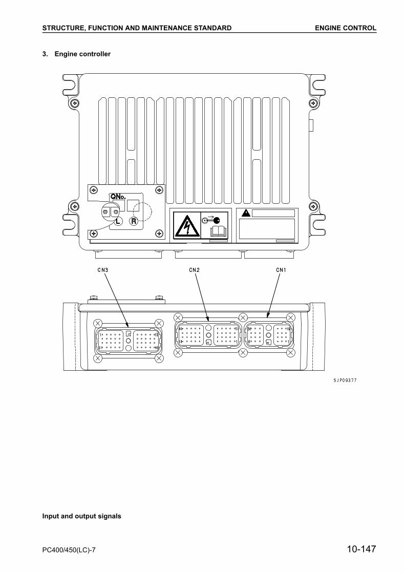
STRUCTURE, FUNCTION AND MAINTENANCE STANDARD ENGINE CONTROL
3. Engine controller
Input and output signals
PC400/450(LC)-7 10-147

STRUCTURE, FUNCTION AND MAINTENANCE STANDARD ENGINE CONTROL
CN1 [CN-E11] CN2 [CN-E12]
Pin No. Signal name Input/Output Pin No. Signal name Input/
OutputCN1-1 POWER (+24V constant) CN2-1 GNDCN1-2 POWER (+24V constant) CN2-2 NCCN1-3 Model selection 1 Input CN2-3 NC InputCN1-4 GND CN2-4 RS232C_1RX InputCN1-5 NC Input CN2-5 NCCN1-6 NC Output CN2-6 NCCN1-7 GND CN2-7 NC InputCN1-8 GND CN2-8 NC InputCN1-9 NC Input CN2-9 Sensor 5V power supply 2 OutputCN1-10 GND CN2-10 Fuel control dial InputCN1-11 NC Input CN2-11 S_NET_SHIELD GNDCN1-12 NC Output CN2-12 CAN_SHIELDCN1-13 Key switch (ACC) Input CN2-13 NC OutputCN1-14 NC Input CN2-14 RS232C_1TX Output
CN1-15 Engine oil pressure switch (For high pressure) Input
CN2-15 G_SHIELD (GND)CN2-16 Ne_SHIELD (GND)
CN1-16 Memory clear Input CN2-17 Fuel temperature sensor InputCN1-17 Model selection 3 Input CN2-18 NC InputCN1-18 NC Output CN2-19 Sensor 5V power supply 1 OutputCN1-19 Key switch (ACC) Input CN2-20 Boost pressure sensor InputCN1-20 Starting switch (C) Input
CN2-21 S_NET (+) Input/Output
CN1-21 Engine oil pressure switch (For low pressure) Input
CN2-22 CAN0_L Input/OutputCN1-22 Auto deceleration signal Input
CN1-23 Model selection 2 Input CN2-23 NCCN1-24 NC Output CN2-24 FWE_switch Input
CN2-25 G pulse (–) InputCN2-26 Ne pulse (–) InputCN2-27 Water temperature sensor (High) InputCN2-28 NC InputCN2-29 Analog GNDCN2-30 NC Input
CN2-31 S_NET (+) Input/Output
CN2-32 CAN0_H Input/Output
CN2-33 NCCN2-34 GND (232C_GND)CN2-35 G pulse (+) InputCN2-36 Ne pulse (+) InputCN2-37 Water temperature sensor (Low) InputCN2-38 NC InputCN2-39 Analog GNDCN2-40 Common rail pressure sensor Input
10-148 PC400/450(LC)-7
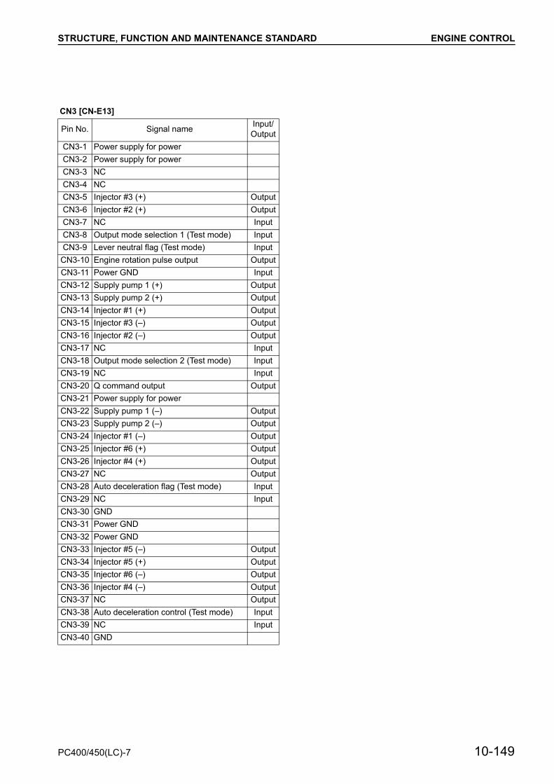
STRUCTURE, FUNCTION AND MAINTENANCE STANDARD ENGINE CONTROL
CN3 [CN-E13]
Pin No. Signal name Input/Output
CN3-1 Power supply for powerCN3-2 Power supply for powerCN3-3 NCCN3-4 NCCN3-5 Injector #3 (+) OutputCN3-6 Injector #2 (+) OutputCN3-7 NC InputCN3-8 Output mode selection 1 (Test mode) InputCN3-9 Lever neutral flag (Test mode) Input
CN3-10 Engine rotation pulse output OutputCN3-11 Power GND InputCN3-12 Supply pump 1 (+) OutputCN3-13 Supply pump 2 (+) OutputCN3-14 Injector #1 (+) OutputCN3-15 Injector #3 (–) OutputCN3-16 Injector #2 (–) OutputCN3-17 NC InputCN3-18 Output mode selection 2 (Test mode) InputCN3-19 NC InputCN3-20 Q command output OutputCN3-21 Power supply for powerCN3-22 Supply pump 1 (–) OutputCN3-23 Supply pump 2 (–) OutputCN3-24 Injector #1 (–) OutputCN3-25 Injector #6 (+) OutputCN3-26 Injector #4 (+) OutputCN3-27 NC OutputCN3-28 Auto deceleration flag (Test mode) InputCN3-29 NC InputCN3-30 GNDCN3-31 Power GNDCN3-32 Power GNDCN3-33 Injector #5 (–) OutputCN3-34 Injector #5 (+) OutputCN3-35 Injector #6 (–) OutputCN3-36 Injector #4 (–) OutputCN3-37 NC OutputCN3-38 Auto deceleration control (Test mode) InputCN3-39 NC InputCN3-40 GND
PC400/450(LC)-7 10-149


STRUCTURE, FUNCTION AND MAINTENANCE STANDARD ELECTRONIC CONTROL SYSTEM
ELECTRONIC CONTROL SYSTEMCONTROL FUNCTIONS
a For the self-diagnosis function, see “TROUBLE SHOOTING”
PC400/450(LC)-7 10-151

STRUCTURE, FUNCTION AND MAINTENANCE STANDARD ELECTRONIC CONTROL SYSTEM
TOTAL SYSTEM DIAGRAM
10-152 PC400/450(LC)-7

STRUCTURE, FUNCTION AND MAINTENANCE STANDARD ELECTRONIC CONTROL SYSTEM
PC400/450(LC)-7 10-153

STRUCTURE, FUNCTION AND MAINTENANCE STANDARD ELECTRONIC CONTROL SYSTEM
1. Engine and Pump control function
10-154 PC400/450(LC)-7

STRUCTURE, FUNCTION AND MAINTENANCE STANDARD ELECTRONIC CONTROL SYSTEM
Function
• The operator can set the work mode switch onthe monitor panel to mode A, E, or B (or L) andselect proper engine torque and pump absorp-tion torque according to the type of work.
• The engine throttle and pump controller detectsthe speed of the engine governor set with the fuelcontrol dial and the actual engine speed and con-trols them so that the pump will absorb all thetorque at each output point of the engine, accord-ing to the pump absorption torque set in eachmode.
: The L mode is on the multi-monitor specificationmachine only.
PC400/450(LC)-7 10-155
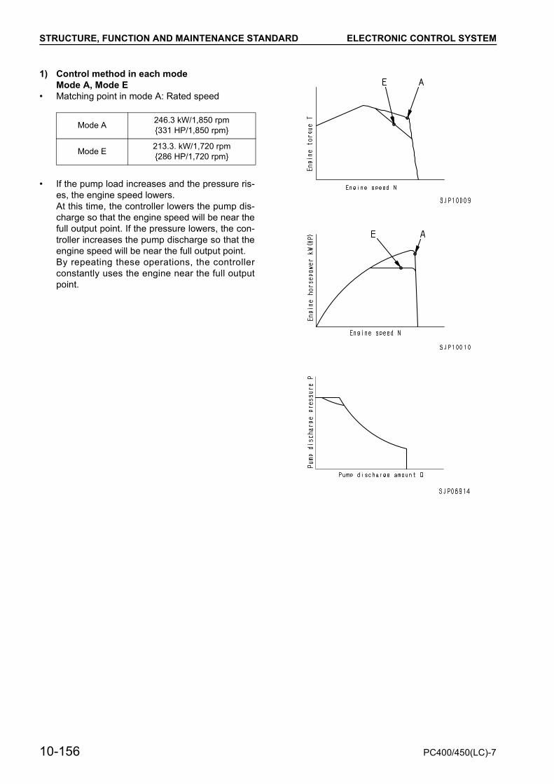
STRUCTURE, FUNCTION AND MAINTENANCE STANDARD ELECTRONIC CONTROL SYSTEM
1) Control method in each modeMode A, Mode E
• Matching point in mode A: Rated speed
• If the pump load increases and the pressure ris-es, the engine speed lowers.At this time, the controller lowers the pump dis-charge so that the engine speed will be near thefull output point. If the pressure lowers, the con-troller increases the pump discharge so that theengine speed will be near the full output point.By repeating these operations, the controllerconstantly uses the engine near the full outputpoint.
Mode A 246.3 kW/1,850 rpm{331 HP/1,850 rpm}
Mode E 213.3. kW/1,720 rpm{286 HP/1,720 rpm}
10-156 PC400/450(LC)-7
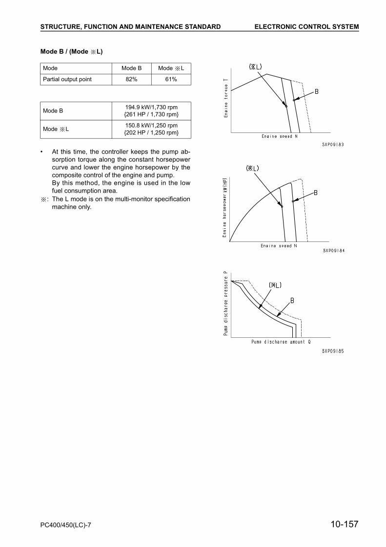
STRUCTURE, FUNCTION AND MAINTENANCE STANDARD ELECTRONIC CONTROL SYSTEM
Mode B / (Mode L)
• At this time, the controller keeps the pump ab-sorption torque along the constant horsepowercurve and lower the engine horsepower by thecomposite control of the engine and pump.By this method, the engine is used in the lowfuel consumption area.
: The L mode is on the multi-monitor specificationmachine only.
Mode Mode B Mode L
Partial output point 82% 61%
Mode B 194.9 kW/1,730 rpm{261 HP / 1,730 rpm}
Mode L 150.8 kW/1,250 rpm{202 HP / 1,250 rpm}
PC400/450(LC)-7 10-157

STRUCTURE, FUNCTION AND MAINTENANCE STANDARD ELECTRONIC CONTROL SYSTEM
2) Function to control pump during travel• When the travel is operated in A operation, or E
or B working mode, the working mode stays as itis, and the pump absorption torque and enginespeed rise to A travel mode.
• If the machine travels in mode L, the workingmode and engine speed do not change, but thepump absorption torque is increased.
: The L mode is on the multi-monitor specificationmachine only.
3) Function to control when emergency pumpdrive switch is turned ON
• Even if the controller or a sensor has a trouble,the functions of the machine can be secured withpump absorption torque almost equivalent tomode E by turning on emergency pump driveswitch (10).In this case, a constant current flows from thebattery to the EPC valve for PC and the oil pres-sure is sensed by only the EPC valve for PC.
10-158 PC400/450(LC)-7
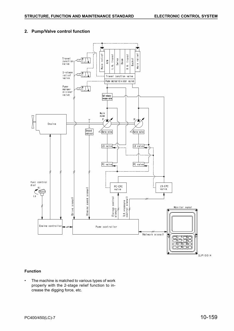
STRUCTURE, FUNCTION AND MAINTENANCE STANDARD ELECTRONIC CONTROL SYSTEM
2. Pump/Valve control function
Function
• The machine is matched to various types of workproperly with the 2-stage relief function to in-crease the digging force, etc.
PC400/450(LC)-7 10-159

STRUCTURE, FUNCTION AND MAINTENANCE STANDARD ELECTRONIC CONTROL SYSTEM
1) LS control function• The change point (LS set differential pressure) of
the pump discharge in the LS valve is changedby changing the output pressure from the LS-EPC valve to the LS valve according to the oper-ating condition of the actuator.
• By this operation, the start-up time of the pumpdischarge is optimized and the composite opera-tion and fine control performance is improved.
2) Cut-off function• When the cut-off function is turned on, the PC-
EPC current is increased to near the maximumvalue.
• By this operation, the flow rate in the relief stateis lowered to reduce fuel consumption.
• Operating condition for turning on cut-off function
The cut-off function does not work, however, whilethe machine is travelling in mode A or the arm craneoperation width swing lock switch is turned on.
1) 2-stage relief function• The relief pressure in the normal work is 34.8
MPa {355 kg/cm2}. If the 2-stage relief function isturned on, however, the relief pressure rises toabout 37.2 MPa {380 kg/cm2}.By this operation, the hydraulic force is increasedfurther.
• Operating condition for turning on 2-stage relieffunction
: The L mode is on the multi-monitor specificationmachine only.
Condition
• The average value of the front and rear pressuresensors is above 27.9 MPa {285 kg/cm2} and theone-touch power maximizing function is not turnedon
Condition Relief pres-sure
• Condition• During travel• When swing lock switch is turned on• When boom is lowered• When one-touch power maximizing
function is turned on• When L mode is operated
34.8 MPa{355 kg/cm2}
37.2 MPa{380 kg/cm2}
10-160 PC400/450(LC)-7

STRUCTURE, FUNCTION AND MAINTENANCE STANDARD ELECTRONIC CONTROL SYSTEM
3. One-touch power maximizing/machine push-up function
Function
• Power can be increased for a certain time by op-erating the left knob switch.
• When the machine push-up switch is operated,the boom pushing force is increased.
PC400/450(LC)-7 10-161
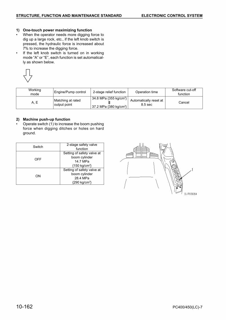
STRUCTURE, FUNCTION AND MAINTENANCE STANDARD ELECTRONIC CONTROL SYSTEM
1) One-touch power maximizing function• When the operator needs more digging force to
dig up a large rock, etc., if the left knob switch ispressed, the hydraulic force is increased about7% to increase the digging force.
• If the left knob switch is turned on in workingmode “A” or “E”, each function is set automatical-ly as shown below.
2) Machine push-up function• Operate switch (1) to increase the boom pushing
force when digging ditches or holes on hardground.
Workingmode Engine/Pump control 2-stage relief function Operation time Software cut-off
function
A, E Matching at rated output point
34.8 MPa {355 kg/cm2}
37.2 MPa {380 kg/cm2}
Automatically reset at 8.5 sec Cancel
Switch 2-stage safety valve function
OFF
Setting of safety valve at boom cylinder
14.7 MPa{150 kg/cm2}
ON
Setting of safety valve at boom cylinder
28.4 MPa{290 kg/cm2}
10-162 PC400/450(LC)-7

STRUCTURE, FUNCTION AND MAINTENANCE STANDARD ELECTRONIC CONTROL SYSTEM
4. Auto-deceleration function
Function
• If the all control levers are set in NEUTRAL whilewaiting for a dump truck or work, the enginespeed is lowered to the medium level automati-cally to reduce the fuel consumption and noise.
• If any lever is operated, the engine speed rises tothe set level instantly.
PC400/450(LC)-7 10-163
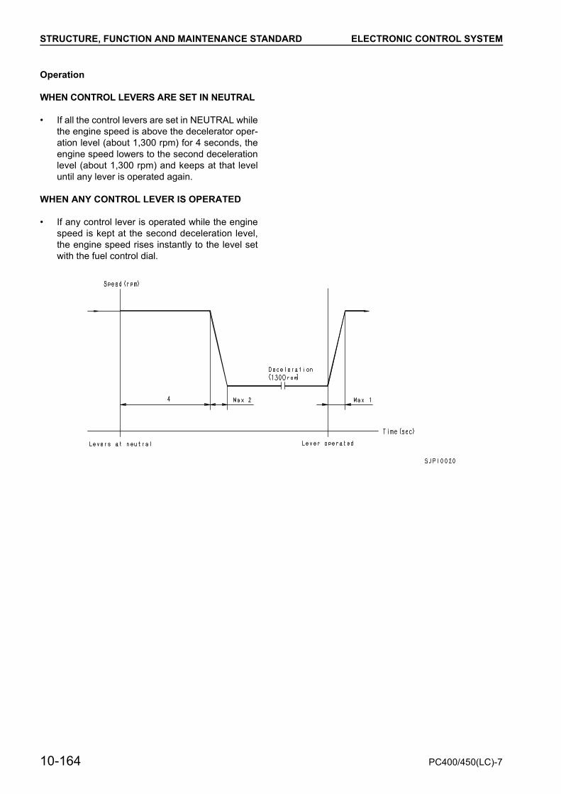
STRUCTURE, FUNCTION AND MAINTENANCE STANDARD ELECTRONIC CONTROL SYSTEM
Operation
WHEN CONTROL LEVERS ARE SET IN NEUTRAL
• If all the control levers are set in NEUTRAL whilethe engine speed is above the decelerator oper-ation level (about 1,300 rpm) for 4 seconds, theengine speed lowers to the second decelerationlevel (about 1,300 rpm) and keeps at that leveluntil any lever is operated again.
WHEN ANY CONTROL LEVER IS OPERATED
• If any control lever is operated while the enginespeed is kept at the second deceleration level,the engine speed rises instantly to the level setwith the fuel control dial.
10-164 PC400/450(LC)-7

STRUCTURE, FUNCTION AND MAINTENANCE STANDARD ELECTRONIC CONTROL SYSTEM
5. Auto-warm-up/Overheat prevention function
Function
• After the engine is started, if the engine coolingwater temperature is low, the engine speed israised automatically to warm up the engine. If theengine cooling water temperature rises too highduring work, the pump load is reduced to preventoverheating.
PC400/450(LC)-7 10-165

STRUCTURE, FUNCTION AND MAINTENANCE STANDARD ELECTRONIC CONTROL SYSTEM
1) Auto-warm-up function• After the engine is started, if the engine cooling
water temperature is low, the engine speed israised automatically to warm up the engine.
2) Overheat prevention function• If the engine cooling water temperature rises too
high during work, the pump load and enginespeed are reduced to prevent overheating.
• This function is turned on when the water tem-perature rises above 95°C.
Operating condition (All) Operated
Water temperature: Below 30°C.Engine speed: Max. 1,200 rpm Engine speed: Max. 1,200 rpm
Resetting condition (Any one) Reset
AutoWater temperature: Above 30°C
Engine speed: Any levelAuto-warm-up operation time: Min. 10 minutes
Manual Fuel control dial: Kept at 70% of full level for 3 sec. or longer
Operating condition Operation/Remedy Resetting condition
Water temperature: Above 105°C
Work mode: Any modeEngine speed: Low idleMonitor alarm lamp: Lights upAlarm buzzer: Sounds
Water temperature: Below 105°CFuel control dial: Return to low idle position once.• Under above condition, controller is
set to condition before operation of function. (Manual reset)
Operating condition Operation/Remedy Resetting condition
Water temperature: Above 102°C
Work mode: Mode A, E, OR BEngine speed: Keep as is.Monitor alarm lamp: Lights up.Lower pump discharge.
Water temperature: Below 102°C• Under above condition, controller is
set to condition before operation of function. (Automatic reset)
Operating condition Operation/Remedy Resetting condition
Water temperature: Above 100°C
Work mode: Mode AEngine speed: Keep as is.Lower pump discharge.
Water temperature: Below 100°C• Under above condition, controller is
set to condition before operation of function. (Automatic reset)
Operating condition Operation/Remedy Resetting condition
Water temperature: Above 95°C
Work mode: TravelEngine speed: Keep as is.Lower travel speed.
Water temperature: Below 95°C• Under above condition, controller is
set to condition before operation of function. (Automatic reset)
10-166 PC400/450(LC)-7
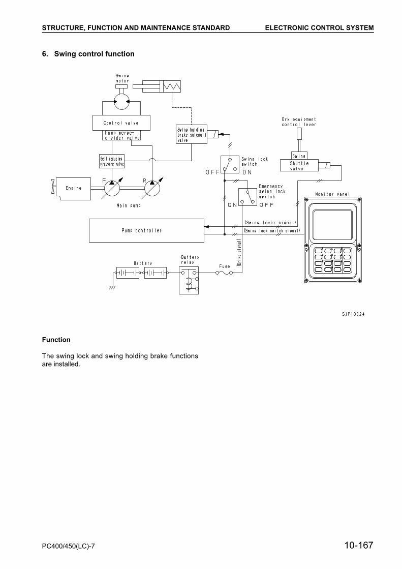
STRUCTURE, FUNCTION AND MAINTENANCE STANDARD ELECTRONIC CONTROL SYSTEM
6. Swing control function
Function
The swing lock and swing holding brake functionsare installed.
PC400/450(LC)-7 10-167
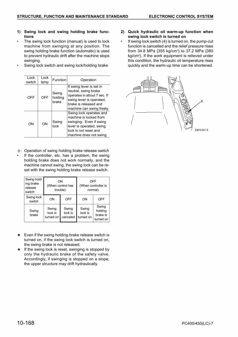
STRUCTURE, FUNCTION AND MAINTENANCE STANDARD ELECTRONIC CONTROL SYSTEM
1) Swing lock and swing holding brake func-tions
• The swing lock function (manual) is used to lockmachine from swinging at any position. Theswing holding brake function (automatic) is usedto prevent hydraulic drift after the machine stopsswinging.
• Swing lock switch and swing lock/holding brake
: Operation of swing holding brake release switch• If the controller, etc. has a problem, the swing
holding brake does not work normally, and themachine cannot swing, the swing lock can be re-set with the swing holding brake release switch.
a Even if the swing holding brake release switch isturned on, if the swing lock switch is turned on,the swing brake is not released.
a If the swing lock is reset, swinging is stopped byonly the hydraulic brake of the safety valve.Accordingly, if swinging is stopped on a slope,the upper structure may drift hydraulically.
2) Quick hydraulic oil warm-up function whenswing lock switch is turned on
• If swing lock switch (4) is turned on, the pump-cutfunction is cancelled and the relief pressure risesfrom 34.8 MPa {355 kg/cm2} to 37.2 MPa {380kg/cm2}. If the work equipment is relieved underthis condition, the hydraulic oil temperature risesquickly and the warm-up time can be shortened.
Lockswitch
Locklamp Function Operation
OFF OFFSwing holding brake
If swing lever is set in neutral, swing brake operates in about 7 sec. If swing lever is operated, brake is released and machine can swing freely.
ON ON Swing lock
Swing lock operates and machine is locked from swinging. Even if swing lever is operated, swing lock is not reset and machine does not swing.
Swing hold-ing brake release switch
ON(When control has
trouble)
OFF (When controller is
normal)
Swing lock switch ON OFF ON OFF
Swing brake
Swing lock is
turned on
Swing lock is
canceled
Swing lock is
turned on
Swing holding brake is
turned on
10-168 PC400/450(LC)-7

STRUCTURE, FUNCTION AND MAINTENANCE STANDARD ELECTRONIC CONTROL SYSTEM
7. Travel control function
Function
• The pumps are controlled and the travel speed ischanged manually or automatically, to secureproper travel performance matched to the type ofwork and jobsite during travel.
PC400/450(LC)-7 10-169
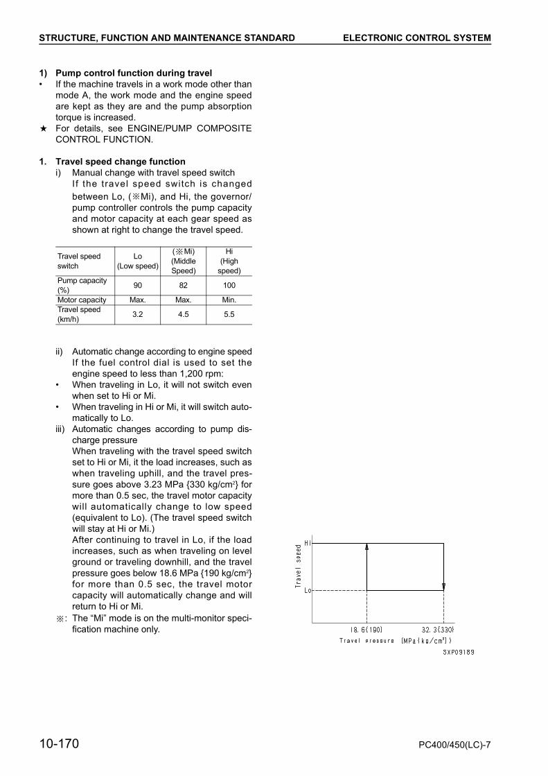
STRUCTURE, FUNCTION AND MAINTENANCE STANDARD ELECTRONIC CONTROL SYSTEM
1) Pump control function during travel• If the machine travels in a work mode other than
mode A, the work mode and the engine speedare kept as they are and the pump absorptiontorque is increased.
a For details, see ENGINE/PUMP COMPOSITECONTROL FUNCTION.
1. Travel speed change functioni) Manual change with travel speed switch
If the travel speed switch is changedbetween Lo, ( Mi), and Hi, the governor/pump controller controls the pump capacityand motor capacity at each gear speed asshown at right to change the travel speed.
ii) Automatic change according to engine speedIf the fuel control dial is used to set theengine speed to less than 1,200 rpm:
• When traveling in Lo, it will not switch evenwhen set to Hi or Mi.
• When traveling in Hi or Mi, it will switch auto-matically to Lo.
iii) Automatic changes according to pump dis-charge pressureWhen traveling with the travel speed switchset to Hi or Mi, it the load increases, such aswhen traveling uphill, and the travel pres-sure goes above 3.23 MPa {330 kg/cm2} formore than 0.5 sec, the travel motor capacitywill automatically change to low speed(equivalent to Lo). (The travel speed switchwill stay at Hi or Mi.)After continuing to travel in Lo, if the loadincreases, such as when traveling on levelground or traveling downhill, and the travelpressure goes below 18.6 MPa {190 kg/cm2}for more than 0.5 sec, the travel motorcapacity will automatically change and willreturn to Hi or Mi.
: The “Mi” mode is on the multi-monitor speci-fication machine only.
Travel speed switch
Lo(Low speed)
( Mi)(Middle Speed)
Hi(High
speed)Pump capacity (%) 90 82 100
Motor capacity Max. Max. Min.Travel speed (km/h) 3.2 4.5 5.5
10-170 PC400/450(LC)-7
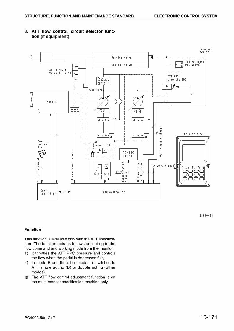
STRUCTURE, FUNCTION AND MAINTENANCE STANDARD ELECTRONIC CONTROL SYSTEM
8. ATT flow control, circuit selector func-tion (if equipment)
Function
This function is available only with the ATT specifica-tion. The function acts as follows according to theflow command and working mode from the monitor.1) It throttles the ATT PPC pressure and controls
the flow when the pedal is depressed fully.2) In mode B and the other modes, it switches to
ATT single acting (B) or double acting (othermodes).
: The ATT flow control adjustment function is onthe multi-monitor specification machine only.
PC400/450(LC)-7 10-171

STRUCTURE, FUNCTION AND MAINTENANCE STANDARD ELECTRONIC CONTROL SYSTEM
9. System component parts1) Engine revolution sensor
Function
• The engine revolution sensor is installed to thering gear of the engine flywheel. It electrically cal-culates the number of the gear teeth which passin front of it and transmits the result to the enginethrottle and pump controller.
• A magnet is used to sense the gear teeth. Eachtime a gear tooth passes in front of the magnet,a current is generated.
1. Sensor2. Locknut3. Wiring harness4. Connector
10-172 PC400/450(LC)-7

STRUCTURE, FUNCTION AND MAINTENANCE STANDARD ELECTRONIC CONTROL SYSTEM
2) PPC oil pressure switch
Specifications
Type of contacts: Normally open contactsOperating (ON) pressure: 0.5 ± 0.1 MPa
{5.0 ± 1.0 kg/cm2}Resetting (OFF) Pressure: 0.3 ± 0.5 MPa
{3.0 ± 0.5 kg/cm2}
Function
• The junction block has 7 pressure switches, whichcheck the operating condition of each actuator bythe PPC pressure and transmit it to the enginethrottle and pump controller.
1. Plug2. Switch3. Connector
PC400/450(LC)-7 10-173

STRUCTURE, FUNCTION AND MAINTENANCE STANDARD ELECTRONIC CONTROL SYSTEM
3) Pump pressure sensor
Function
• The pump pressure sensor is installed to the inletcircuit of the control valve. It converts the pumpdischarge pressure into a voltage and transmitsit to the engine throttle and pump controller.
Operation
• The oil pressure applied from the pressure intakepart presses the diaphragm of the oil pressuresensor, the diaphragm is deformed.
• The gauge layer facing the diaphragm measuresthe deformation of the diaphragm by the changeof its resistance, then converts the change of theresistance into a voltage and transmits it to theamplifier (voltage amplifier).
• The amplifier amplifies the received voltage andtransmits it to the engine throttle and pump con-troller.
• Relationship between pressure P (MPa {kg/cm2})and output voltage (V) is as follows.V = 0.08 [0.008] × P + 0.5
1. Sensor2. Connector
10-174 PC400/450(LC)-7
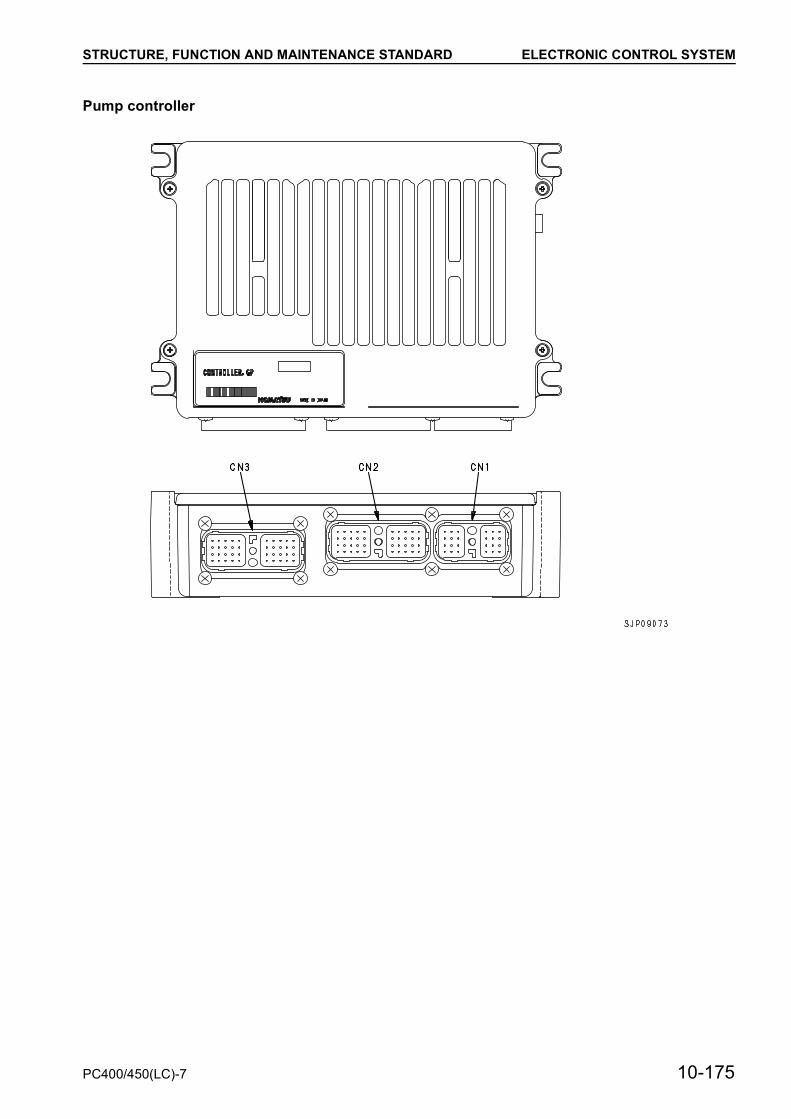
STRUCTURE, FUNCTION AND MAINTENANCE STANDARD ELECTRONIC CONTROL SYSTEM
Pump controller
PC400/450(LC)-7 10-175
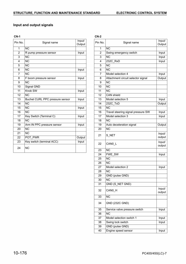
STRUCTURE, FUNCTION AND MAINTENANCE STANDARD ELECTRONIC CONTROL SYSTEM
Input and output signals
CN-1 CN-2
Pin No. Signal name Input/Output Pin No. Signal name Input/
Output1 NC 1 NC2 R pump pressure sensor Input 2 Swing emergency switch Input3 NC 3 NC Input4 NC 4 232C_RxD Input5 NC 5 NC6 NC Input 6 NC7 NC 7 Model selection 4 Input8 F boom pressure sensor Input 8 Attachment circuit selector signal Output9 NC 9 NC
10 Signal GND 10 NC11 Knob SW Input 11 NC12 NC 12 CAN shield13 Buchet CURL PPC pressure sensor Input 13 Model selection 5 Input14 NC 14 232C_TxD Output15 NC Input 15 NC16 NC 16 Travel steering signal pressure SW Input17 Key Switch (Terminal C) Input 17 Model selection 3 Input18 NC 18 NC19 Arm IN PPC pressure sensor Input 19 Auto deceleration signal Output20 NC 20 NC21 NC
21 S_NET Input/output22 POT_PWR Output
23 Key switch (terminal ACC) Input22 CAN0_L Input/
output24 NC
23 NC24 FWE_SW Input25 NC26 NC27 Model selection 2 Input28 NC29 GND (pulse GND)30 NC31 GND (S_NET GND)
32 CAN0_H Input/output
33 NC
34 GND (232C GND)
35 Service valve pressure switch Input36 NC37 Model selection switch 1 Input38 Swing lock switch Input39 GND (pulse GND)40 Engine speed sensor Input
10-176 PC400/450(LC)-7

STRUCTURE, FUNCTION AND MAINTENANCE STANDARD ELECTRONIC CONTROL SYSTEM
CN-3
Pin No. Signal name Input/Output
1 VB (controller power) Input 2 VIS (solenoid power) Input 3 SOL_COM (solenoid common gnd) 4 Battery relay drive Output 5 NC 6 LS-EPC Output 7 Travel junction SOL Output 8 NC 9 NC Input10 Boom RAISE pressure SW Input11 VB (controller power) Input12 VIS (solenoid power) Input13 SOL_COM (solenoid common gnd) Input14 KEY_SIG Input15 NC16 PC-EPC Output17 Pump merge/divider solenoid Output18 Heater relay drive Output19 Bucket DUMP pressure switch Input20 Boom LOWER pressure switch Input21 GND (controller GND) Input22 NC23 SOL_COM (solenoid common gnd) Input24 KEY_SIG Input25 NC26 Service flow adjustment EPC (1) Output27 Travel Hi/Lo selector solenoid Output28 2-stage relief solenoid Output29 Swing pressure switch Input30 Arm IN pressure switch31 NC Input32 GND (controller GND) Input33 GND (controller GND) Input34 NC35 NC36 NC37 Swing parking brake solenoid Output38 NC39 Travel pressure switch Input40 Arm OUT pressure switch Input
PC400/450(LC)-7 10-177

STRUCTURE, FUNCTION AND MAINTENANCE STANDARD MONITOR SYSTEM
MONITOR SYSTEM
• The monitor system monitors the condition of themachine with sensors installed on various partsof the machine. It processes and immediatelydisplays the obtained information on the panelnotifying the operator of the condition of the ma-chine.The panel is roughly divided as follows.1. Monitor section to output alarms when the
machine has troubles2. Gauge section to display the condition con-
stantly (Coolant temperature, hydraulic oiltemperature, fuel level, etc.)
• The monitor panel also has various mode selec-tor switches and functions to operate the ma-chine control system.
10-178 PC400/450(LC)-7

STRUCTURE, FUNCTION AND MAINTENANCE STANDARD MONITOR SYSTEM
1. Monitor panel
Outline
• The monitor panel has the functions to displayvarious items and the functions to select modesand electric parts.The monitor panel has a CPU (Central Process-ing Unit) in it to process, display, and output theinformation.The monitor display unit consists of LCD (LiquidCrystal Display). The switches are flat sheetswitches.
PC400/450(LC)-7 10-179

STRUCTURE, FUNCTION AND MAINTENANCE STANDARD MONITOR SYSTEM
Input and output signalsCN-1 CN3Pin No. Signal name Input/
outputPin No. Signal name Input/
output1 Key ON Input 1 NC Input2 Key ON Input 2 NC Input3 Washer motor output Output 3 NC Input4 Starting signal Input 4 NC Input5 Limit switch (W) Input 5 NC Input6 GND 6 NC Input7 GND 7 RS230C CTS Input8 VB + Input 8 RS230C RXD Input9 Wiper motor (+) Output
9 RS230C RXD Input/Output10 Wiper motor (-) Output
11 Buzzer ON signal Input10 RS230C RXD Input/
Output12 Limit switch (P) Input11 BOOTSW Input12 NC Input
CN-2 13 GNDPin No. Signal name Input/
output 14 CAN (SHIELD) Input
1 Engine water temperature Input 15 CAN (+) Input 2 Fuel level Input 16 CAN (-) Input 3 Radiator water level Input 4 (Hydraulic oil level) Input 5 Air cleaner clogging Input 6 NC Input 7 Engine oil pressure Input 8 Engine oil level Input
9 N/W signal Input/Output
10 N/W signal Input/Output
11 Battery charge Input12 Hydraulic oil temperature (analog) Input13 GND (for analog signal)14 Buzzer drive Input15 Limit SW (window) Input16 Buzzer cancel Input17 Swing lock Input18 Preheat Input19 Light switch Input20 N/W GND
10-180 PC400/450(LC)-7

STRUCTURE, FUNCTION AND MAINTENANCE STANDARD MONITOR SYSTEM
MONITOR CONTROL, DISPLAY PORTION
MONITOR PORTION
1. Wiper motor 11. Fuel level monitor2. Preheating monitor 12. Hydraulic oil temperature monitor3. Swing lock monitor 13. Power max. monitor4. Engine water temperature monitor 14. Auto-deceleration monitor5. Hydraulic oil temperature gauge 15. Radiator water level caution6. Engine water temperature gauge 16. Battery charge caution7. Working mode monitor 17. Engine oil pressure caution8. Service monitor 18. Engine oil level caution9. Travel speed monitor 19. Air cleaner clogging
10. Fuel gauge 20. Maintenance time warning caution
PC400/450(LC)-7 10-181

STRUCTURE, FUNCTION AND MAINTENANCE STANDARD MONITOR SYSTEM
MONITOR ITEMS AND DISPLAY
Symbol Display item Display method
Swing lock
Swing lock switch Swing holding brake release switch Swing lock monitor
OFF OFF OFF
ON OFF ON
OFF ON Flashes
ON ON ON
Preheating
Continuous set time Preheating monitor status
Up to 30 sec. ON
From 30 sec. to 40 sec. Flashes
More than 40 sec. OFF
Power Max
Power Max. switch status Power Max. monitor status
Being pressed Lights up but goes out after approx. 9 sec when kept pressed
Not being pressed Flashes
Engine water temperature
See gauge display on the next pageHydraulic oil temperature
Fuel level
10-182 PC400/450(LC)-7

STRUCTURE, FUNCTION AND MAINTENANCE STANDARD MONITOR SYSTEM
Gauge Range Temperature, volume Indicator Buzzer sound
Engine water temperature (°C)
A1 105 Red
A2 102 Red
A3 100 Green
A4 80 Green
A5 60 Green
A6 30 White
Hydraulic oil tempera-ture (°C)
B1 105 Red
B2 102 Red
B3 100 Green
B4 80 Green
B5 40 Green
B6 20 White
Fuel level (l)
C1 467 Green
C2 381 Green
C3 295 Green
C4 147.5 Green
C5 114 Green
C6 80.5 Red
PC400/450(LC)-7 10-183

STRUCTURE, FUNCTION AND MAINTENANCE STANDARD MONITOR SYSTEM
Checks before starting (caution lamps all light up), when maintenance interval is exceeded.If the checks before starting or maintenance interval is exceeded items light up, the display of the hydraulic oiltemperature gauge and the hydraulic oil temperature monitor are stopped, and the following cautions are dis-played.
The problems that have occurred are displayed in order from the left.
When the above cautions are displayed, if the hydraulic oil temperature is high or low, only the symbol is dis-played.
Symbol Display item Check before starting item
When engine is stopped
When engine is running
Engine oil pressure q —When abnormal,
lights up and buzzer sounds
Battery charge q — Lights up when abnormal
Radiator water level q Lights up when abnormal
When abnormal, lights up and buzzer
sounds
Engine oil level q Lights up when abnormal —
Air cleaner clogging q — Lights up when abnormal
MaintenanceLights up when there is a warning. Lights up for only 30 sec. after key is turned ON, then goes out.
Condition of hydraulic oil Color of symbol
Low temperature (below B6 or equivalent) Black on white background
Normal (B6 – B2) No display
High temperature (below B2) White on red background
10-184 PC400/450(LC)-7

STRUCTURE, FUNCTION AND MAINTENANCE STANDARD MONITOR SYSTEM
Display category Symbol Display item Display range Display method
Monitor
Wiper Displays set condition
Working mode Displays set mode
Travel speed Displays set speed
Auto-decelera-tion ON OFF Displays actuation
status
Service meter Service meter indicator When service meter is working Lights up when service
meter is working
ON INT OFF
PC400/450(LC)-7 10-185

STRUCTURE, FUNCTION AND MAINTENANCE STANDARD MONITOR SYSTEM
SWITCHES
1. Selector switch2. Selector switch3. Display brightness, contrast adjustment switch4. Control switch5. Window washer switch6. Wiper switch7. Maintenance switch8. Travel speed selector switch9. Auto-deceleration switch
10-186 PC400/450(LC)-7

STRUCTURE, FUNCTION AND MAINTENANCE STANDARD MONITOR SYSTEM
• Working mode selector switchThe condition of the machine changes accord-ing to the switch that is pressed (A, E, L, B). It ispossible to check the condition on the workingmode monitor display. The relationship betweeneach working mode and the monitor display isshown in the table on the right.
• Selector switchThis is used when making detailed settings ineach working mode. (For details, see ATTACH-MENT FLOW CONTROL FUNCTION for modesA and E.)
• Maintenance switchCheck the condition of the maintenance items.(For details, see MAINTENANCE FUNCTION.)
• Auto-deceleration switchEach time the auto-deceleration switch ispressed, the auto-deceleration function isswitched ON/OFF. Use the auto-deceleration monitor display tocheck the present condition. When the working mode switch is operated toswitch the working mode, it is automatically setto ON.
• Travel speed selector switchEach time the travel speed selector switch ispressed, the travel speed changes.Lo o Hi o Lo ……Use the travel speed monitor display to checkthe present condition.The relationship between the set speed and themonitor display in the table on the right.
• Wiper switchEach time the wiper switch is pressed, the wipersetting changes OFF o INT o ON o OFF o……Use the wiper monitor display to check thepresent condition.The relationship between the wiper setting andthe monitor display is as shown in the table onthe right.
Switch that is pressed Display Working mode status
after setting
[A] A A mode (default)
[E] E E mode
[L] L Heavy-lift mode
[B] B Swing priority mode
Display Setting
Crawler symbol + Lo Low speed (default)
Crawler symbol + Mi Medium speed
Crawler symbol + Hi High speed
Display Setting Wiper actuation status
None OFF Stowing stopped or now stowing
Wiper symbol + INT INT Intermittent actuation
Wiper symbol + ON ON Continuous actuation
PC400/450(LC)-7 10-187

STRUCTURE, FUNCTION AND MAINTENANCE STANDARD MONITOR SYSTEM
• Window washer switchWhile the switch is being pressed, windowwasher liquid is sprayed out. There is a timedelay before the wiper starts.
• Control switchThis is used for control when using the mainte-nance function or select function.(For details, see each function.)
• Display brightness, contrast adjustment switchUse this switch when adjusting the displaybrightness and contrast.(For details, see each function.)
10-188 PC400/450(LC)-7

STRUCTURE, FUNCTION AND MAINTENANCE STANDARD MONITOR SYSTEM
SELECT MODE FUNCTION
• This is used when setting the flow in each work-ing mode. It is possible to make the setting whengenuine attachment piping is installed and the in-itial value setting function on the service menuhas been used to set to ATTACHMENT IN-STALLED.
• It is possible to check on the working mode mon-itor if this function can be set.
MEHOD OF USE
a Carry out the setting on the normal screen1. A mode, E mode
1) Press select switch (1) on the monitor tomove to the adjustment screen.
2) Press control switch (2) to select the flowlevel.
3) After completing the level selection, pressinput confirmation switch (3).The selection flow level is confirmed and thescreen moves to the normal screen.From the moment that the flow level isselected, the content of the selection isreflected for the attachment flow.a Before the input confirmation switch is
pressed, the flow level is not confirmed,so press return switch (4) to return to thenormal screen. This function can beused to return to the previously set flow.The relationship between the set flowlevel and the flow value is as shown inthe table on the right.
Working mode Monitor display
A mode [A] + crusher symbol
E mode [E] + crusher symbol
B mode [B] + flow symbol
Control switch Actuation
Flow level bar graph extends to the right
Flow level bar graph retracts to the left
Flow level Flow (L/min.) Remarks
8 530 Default
7 430
6 370
5 300
4 230
3 165
2 100
1 30
PC400/450(LC)-7 10-189

STRUCTURE, FUNCTION AND MAINTENANCE STANDARD MONITOR SYSTEM
2. B mode1) Press select switch (1) on the monitor to
move to the screen for selecting the 3-stageflow level.
2) Press control switch (2), or input [01] – [03]with the numeral 10-key pad to choose oneon the three flow levels.
3) After completing the level selection, pressinput confirmation switch (3).The selected flow level is selected.a Before the input confirmation switch is
pressed, the flow level is not confirmed,so press return switch (4) to return to theoperator screen. This function can beused to return to the previously set flow.
4) After the flow level is confirmed, the screenchanges to the screen shown in the diagramon the right.With this screen, it is possible to make fineadjustment to the flow.
5) Press control switch (2) and select the flowlevel.
No. 10-key pad operation
01
02
03
Control switch Actuation
Flow level bar graph extends to the right
Flow level bar graph retracts to the left
No. Flow level (L/min.) Remarks
01 230 Default
02 190
03 150
10-190 PC400/450(LC)-7

STRUCTURE, FUNCTION AND MAINTENANCE STANDARD MONITOR SYSTEM
6) After completing the level selection, pressinput confirmation switch (3).The selected flow level is confirmed and thescreen moves to the operator screen.From the moment that the flow level isselected, the content of the selection isreflected for the attachment flow.a Before the input confirmation switch is
pressed, the flow level is not confirmed,se press return switch (4) to return to thenormal screen. This function can beused to return to the previously set flow.The relationship between the set flowlevel and the flow value is as shown inthe table on the right.
7) Check the set value with the working modemonitor.The relationship between the display leveland the set value is as shown in the table onthe right, and it is possible to check the levelof the flow that can be set.
Flow level
When flow is 140 l/min.
When flow is 220 l/min.
When flow is 300 l/min.
Remarks
7 200 280 360
6 180 260 340
5 160 240 320
4 140 220 300 Default
3 120 200 280
2 100 180 260
1 80 160 240
Display level Set value (l/min.)
8 220 or 360
7 200 or 340
6 180 or 320
5 160 or 300
4 140 or 280
3 120 or 260
2 100 or 240
1 80
PC400/450(LC)-7 10-191

STRUCTURE, FUNCTION AND MAINTENANCE STANDARD MONITOR SYSTEM
MAINTENANCE FUNCTION
When the maintenance time for replacement,inspection, or filling has approached for the 10 main-tenance items, press maintenance switch (1) andthe caution display (yellow or red) appears on themonitor display for 30 seconds after the key isturned ON to remind the operator to carry out lubri-cation maintenance.
a Maintenance items
a The above replacement intervals are set foreach item, and the time remaining to mainte-nance is reduced as the machine is operated.The content of the caution display differsaccording to the ramaining time. The relation-ship is as shown in the table below.
No. Item Replacement interval (hours)
01 Engine oil 500
02 Engine oil filter 500
03 Fuel filter 500
04 Hydraulic filter 1000
05 Hydraulic tank breather 500
06 Corrosion resistor 1000
07 Damper case oil 1000
08 Final case oil 2000
09 Machinery case oil 1000
10 Hydraulic oil 5000
Display Condition
NoneRemaining time for mainte-nance for all items is more
than 30 hours
Notice display (black sym-bol displayed on yellow
background)
There is one or more items with less than 30 hours
remaining time for mainte-nance
Warning display (wiper symbol displayed on red
background)
There is one or more items with less than 0 hours
remaining time for mainte-nance
10-192 PC400/450(LC)-7

STRUCTURE, FUNCTION AND MAINTENANCE STANDARD MONITOR SYSTEM
METHOD OF CHECKING STATUS MAINTENANCE ITEMS
a Operate as follows when on the operatorscreen.
1. Press maintenance switch (1) and switch to themaintenance list display screen.a The maintenance items are displayed as
symbols on the screen.2. Press control switch (2), or use the 10-key pad
to input the number (01 – 10) of the mainte-nance item to select the item.a The cursor moves and the item is highlight-
ed.a The display method is the same as de-
scribed on the previous page (relationshipbetween remaining time and caution dis-play). If the remaining time is less than 30hours, the item is displayed in yellow, and ifit is less than 0 hours, it is displayed in red.
MAINTENANCE OPERATION
1. After completing the selection, press input con-firmation switch (3).The screen will change to the maintenancereset screen.
2. Use the maintenance reset screen to check thecontent, and if there is any problem, press inputconfirmation switch (3) to move to the checkscreen.If the wrong item is selected, press return switch(4) to return to the maintenance list screen.
3. Check the content on the check screen, and ifthere is no problem, press input confirmationswitch (3) to reset the maintenance time.After the reset is completed, the screen returnsto the maintenance list display screen. To checkthe remaining time, or if the wrong item isselected, press return switch (4) to return to themaintenance list screen.a The check screen shows the symbol for the
maintenance item and the set time in largeletters.
a The background color of the symbol for theitem where the maintenance item was resetis the same as the background of the screen,so it is possible to check that it has been re-set.
PC400/450(LC)-7 10-193

STRUCTURE, FUNCTION AND MAINTENANCE STANDARD MONITOR SYSTEM
BRIGHTNESS, CONTRAST ADJUSTMENTFUNCTION
This function is used to adjust the brightness andcontrast of the display.
ADJUSTMENT METHOD
a Operate as follows when on the operatorscreen.
1. Press display brightness/contrast adjustmentswitch (1) and switch to the adjustment screen.
a Relationship between menu symbol and con-tent.
2. Press control switch (2), or use the 10-key padto input the number (00 – 02) to select eithercontrast or brightness.After completing the selection, press input con-firmation switch (3) and return to the adjustmentscreen.Then press return switch (4) or use the 10-keypas to set to [00] and press input confirmationswitch (3) to return to the normal screen.
3. Press control switch (2) and adjust the bright-ness and contrast as desired.
No. Symbol Content
01 Return mark Return
02 Contrast
03 Brightness
Control switch Actuation
Flow level bar graph extends to the right
Flow level bar graph retracts to the left
10-194 PC400/450(LC)-7
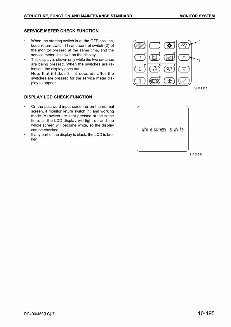
STRUCTURE, FUNCTION AND MAINTENANCE STANDARD MONITOR SYSTEM
SERVICE METER CHECK FUNCTION
• When the starting switch is at the OFF position,keep return switch (1) and control switch (2) ofthe monitor pressed at the same time, and theservice meter is shown on the display.
• This display is shown only while the two switchesare being pressed. When the switches are re-leased, the display goes out.Note that it takes 3 – 5 seconds after theswitches are pressed for the service meter dis-play to appear.
DISPLAY LCD CHECK FUNCTION
• On the password input screen or on the normalscreen, if monitor return switch (1) and workingmode (A) switch are kept pressed at the sametime, all the LCD display will light up and thewhole screen will become white, so the displaycan be checked.
• If any part of the display is black, the LCD is bro-ken.
PC400/450(LC)-7 10-195

STRUCTURE, FUNCTION AND MAINTENANCE STANDARD MONITOR SYSTEM
USER CODE DISPLAY FUNCTION
• If there is any problem in operating the machine,the user code is displayed on the monitor to ad-vise the operator of the steps to take.This code display appears on the operatorscreen.
• On the operator screen, the user code is dis-played on the portion for the hydraulic oil temper-ature gauge.
• If more than one user code is generated at thesame time, the user codes are displayed in turnfor 2 seconds each to display all the user codes.
10-196 PC400/450(LC)-7
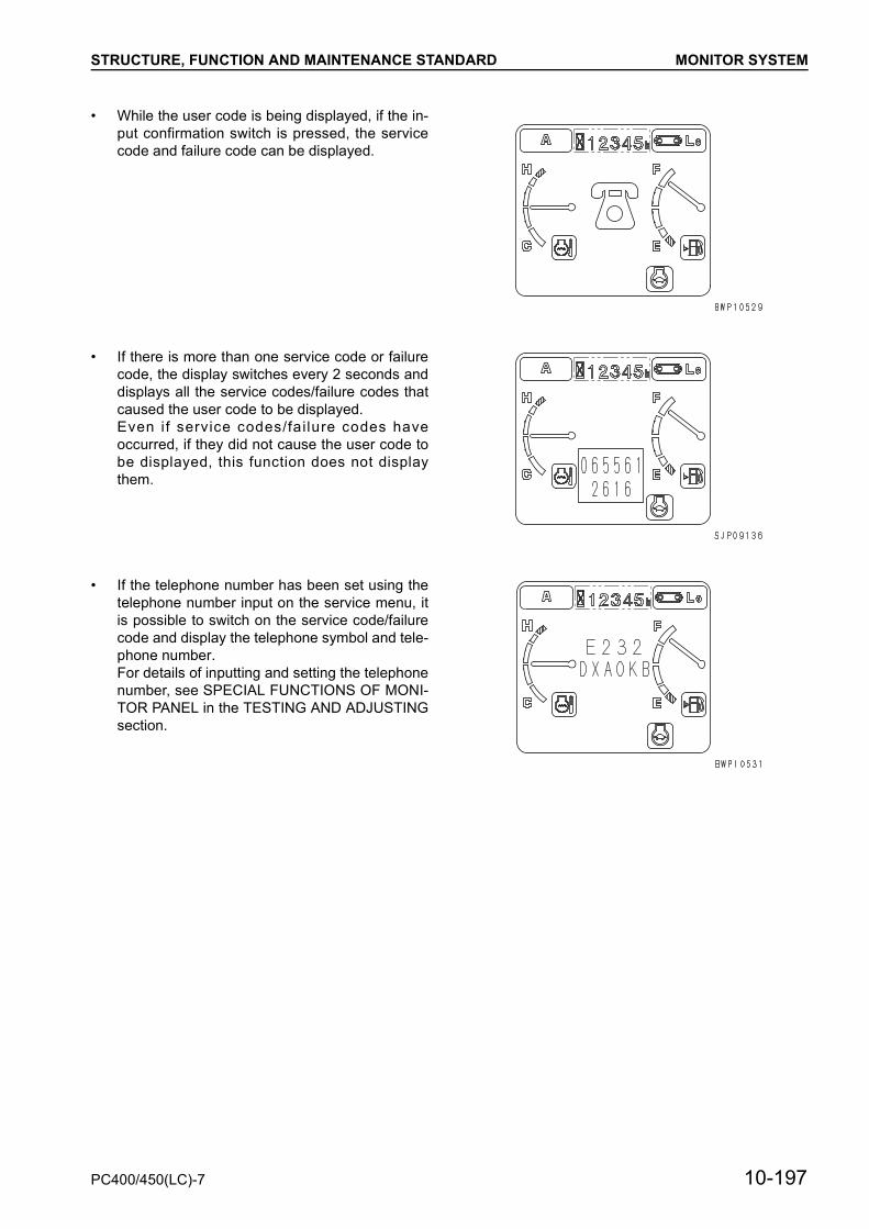
STRUCTURE, FUNCTION AND MAINTENANCE STANDARD MONITOR SYSTEM
• While the user code is being displayed, if the in-put confirmation switch is pressed, the servicecode and failure code can be displayed.
• If there is more than one service code or failurecode, the display switches every 2 seconds anddisplays all the service codes/failure codes thatcaused the user code to be displayed.Even i f service codes/failure codes haveoccurred, if they did not cause the user code tobe displayed, this function does not displaythem.
• If the telephone number has been set using thetelephone number input on the service menu, itis possible to switch on the service code/failurecode and display the telephone symbol and tele-phone number.For details of inputting and setting the telephonenumber, see SPECIAL FUNCTIONS OF MONI-TOR PANEL in the TESTING AND ADJUSTINGsection.
PC400/450(LC)-7 10-197

STRUCTURE, FUNCTION AND MAINTENANCE STANDARD SENSOR
SENSOR• The signals from the sensors are input to the
panel directly. Either side of a sensor of contacttype is always connected to the chassis ground.
Name of sensor Type of sensor When normal When abnormal
Engine oil level Contact ON (closed) OFF (open)
Engine oil pressure Contact OFF (open) ON (closed)
Hydraulic oil temperature Resistance — —
Coolant temperature Resistance — —
Fuel level Resistance — —
Air cleaner clogging Contact type OFF (open) ON (closed)
10-198 PC400/450(LC)-7

STRUCTURE, FUNCTION AND MAINTENANCE STANDARD SENSOR
Engine oil level sensor
Engine oil pressure sensor (For low pressure)
Coolant temperature sensorHydraulic oil temperature sensor
1. Connector2. Bracket3. Float4. Switch
1. Plug2. Contact ring3. Contact4. Diaphragm5. Spring6. Terminal
1. Thermistor 4. Tube2. Body 5. Wire3. Tube 6. Connector
PC400/450(LC)-7 10-199

STRUCTURE, FUNCTION AND MAINTENANCE STANDARD SENSOR
Fuel level sensor
Air cleaner clogging sensor
1. Float2. Connector3. Cover4. Variable resistor
10-200 PC400/450(LC)-7

PC400/450(LC)-7 90-1
HYDRAULIC CIRCUIT DIAGRAM (1/2)........................................................................................................90- 3HYDRAULIC CIRCUIT DIAGRAM (2/2)........................................................................................................90- 5ELECTRICAL CIRCUIT DIAGRAM (1/5) ......................................................................................................90- 7ELECTRICAL CIRCUIT DIAGRAM (2/5) ......................................................................................................90- 9ELECTRICAL CIRCUIT DIAGRAM (3/5) ......................................................................................................90- 11ELECTRICAL CIRCUIT DIAGRAM (4/5) ......................................................................................................90-13ELECTRICAL CIRCUIT DIAGRAM (5/5) ......................................................................................................90-15AIR CONDITIONER ELECTRICAL CIRCUIT ...............................................................................................90-17
90 OTHERS