Embed Size (px)
Citation preview

A platform for developing
Intelligent MultiMedia applications
Tom Br�ndsted, Paul Dalsgaard, Lars Bo Larsen,
Michael Manthey, Paul Mc Kevitt, Thomas B. Moeslund,
and Kristian G. Olesen
Technical Report R-98-1004
May, 1998
Center for PersonKommunikation (CPK)
Fredrik Bajers Vej 7A-5
Institute for Electronic Systems
Aalborg University
DK-9220, Aalborg �, Denmark
E-mail: [email protected] { Fax: (+45) 98 15 15 83 { Tel: (+45) 96 35 86 40

ISSN 0908-1224
A platform for developingIntelligent MultiMedia applications
Tom Br�ndsted, Paul Dalsgaard, Lars Bo Larsen,
Michael Manthey, Paul Mc Kevitt1, Thomas B. Moeslund,
and Kristian G. Olesen
Institute for Electronic Systems (IES)
Fredrik Bajers Vej 7
Aalborg University
DK-9220, Aalborg �, Denmark
E-mail: [email protected]
1Paul Mc Kevitt is also a British Engineering and Physical Sciences Research Council (EPSRC)
Advanced Fellow at the University of She�eld, England for �ve years under grant B/94/AF/1833
for the Integration of Natural Language, Speech and Vision Processing.

Contents
Abstract
1 Introduction 1
1.1 Background . . . . . . . . . . . . . . . . . . . . . . . . . . . . . . . . . . . 11.2 IntelliMedia 2000+ . . . . . . . . . . . . . . . . . . . . . . . . . . . . . . . 3
1.2.1 Computer Science (CS) . . . . . . . . . . . . . . . . . . . . . . . . . 41.2.2 Medical Informatics (MI) . . . . . . . . . . . . . . . . . . . . . . . . 51.2.3 Laboratory of Image Analysis (LIA) . . . . . . . . . . . . . . . . . 51.2.4 Center for PersonKommunikation (CPK) . . . . . . . . . . . . . . . 6
1.3 Education . . . . . . . . . . . . . . . . . . . . . . . . . . . . . . . . . . . . 81.4 Choosing a demonstrator . . . . . . . . . . . . . . . . . . . . . . . . . . . . 8
1.4.1 Requirements . . . . . . . . . . . . . . . . . . . . . . . . . . . . . . 81.4.2 Candidate applications . . . . . . . . . . . . . . . . . . . . . . . . . 9
2 CHAMELEON and the IntelliMedia WorkBench 12
2.1 IntelliMedia WorkBench . . . . . . . . . . . . . . . . . . . . . . . . . . . . 122.2 Sample dialogue interaction . . . . . . . . . . . . . . . . . . . . . . . . . . 142.3 Architecture of CHAMELEON . . . . . . . . . . . . . . . . . . . . . . . . 172.4 DACS . . . . . . . . . . . . . . . . . . . . . . . . . . . . . . . . . . . . . . 212.5 Summary . . . . . . . . . . . . . . . . . . . . . . . . . . . . . . . . . . . . 22
3 Dialogue management 24
3.1 Frame semantics . . . . . . . . . . . . . . . . . . . . . . . . . . . . . . . . 243.1.1 Input frames . . . . . . . . . . . . . . . . . . . . . . . . . . . . . . 253.1.2 Output frames . . . . . . . . . . . . . . . . . . . . . . . . . . . . . 253.1.3 Integration frames . . . . . . . . . . . . . . . . . . . . . . . . . . . 263.1.4 Coding of frames . . . . . . . . . . . . . . . . . . . . . . . . . . . . 27
3.2 Blackboard . . . . . . . . . . . . . . . . . . . . . . . . . . . . . . . . . . . 283.2.1 Functionality . . . . . . . . . . . . . . . . . . . . . . . . . . . . . . 293.2.2 Blackboard architecture . . . . . . . . . . . . . . . . . . . . . . . . 313.2.3 Status of blackboard . . . . . . . . . . . . . . . . . . . . . . . . . . 31
3.3 Dialogue manager . . . . . . . . . . . . . . . . . . . . . . . . . . . . . . . . 323.4 DACS and CHAMELEON . . . . . . . . . . . . . . . . . . . . . . . . . . . 33

ii CONTENTS
3.5 Summary . . . . . . . . . . . . . . . . . . . . . . . . . . . . . . . . . . . . 34
4 Domain model 35
4.1 The physical environment . . . . . . . . . . . . . . . . . . . . . . . . . . . 354.2 The people . . . . . . . . . . . . . . . . . . . . . . . . . . . . . . . . . . . . 374.3 Functionality . . . . . . . . . . . . . . . . . . . . . . . . . . . . . . . . . . 384.4 The path planner . . . . . . . . . . . . . . . . . . . . . . . . . . . . . . . . 414.5 Implementation . . . . . . . . . . . . . . . . . . . . . . . . . . . . . . . . . 414.6 Future extensions . . . . . . . . . . . . . . . . . . . . . . . . . . . . . . . . 424.7 Summary . . . . . . . . . . . . . . . . . . . . . . . . . . . . . . . . . . . . 42
5 Gesture 43
5.1 Gesture tracking . . . . . . . . . . . . . . . . . . . . . . . . . . . . . . . . 435.1.1 Gesture tracker . . . . . . . . . . . . . . . . . . . . . . . . . . . . . 445.1.2 Temporal segmentation of tracker output . . . . . . . . . . . . . . . 485.1.3 Calibration . . . . . . . . . . . . . . . . . . . . . . . . . . . . . . . 49
5.2 Laser system . . . . . . . . . . . . . . . . . . . . . . . . . . . . . . . . . . 515.2.1 Laser device . . . . . . . . . . . . . . . . . . . . . . . . . . . . . . . 515.2.2 Laser control . . . . . . . . . . . . . . . . . . . . . . . . . . . . . . 535.2.3 Calibration . . . . . . . . . . . . . . . . . . . . . . . . . . . . . . . 53
5.3 Summary . . . . . . . . . . . . . . . . . . . . . . . . . . . . . . . . . . . . 54
6 Speech 55
6.1 Speech recogniser . . . . . . . . . . . . . . . . . . . . . . . . . . . . . . . . 556.1.1 Requirements . . . . . . . . . . . . . . . . . . . . . . . . . . . . . . 556.1.2 Speci�cations . . . . . . . . . . . . . . . . . . . . . . . . . . . . . . 566.1.3 Choice of speech recogniser . . . . . . . . . . . . . . . . . . . . . . 566.1.4 Con�guration, vocabulary and grammars . . . . . . . . . . . . . . . 576.1.5 Speech recognition example . . . . . . . . . . . . . . . . . . . . . . 57
6.2 Speech synthesiser . . . . . . . . . . . . . . . . . . . . . . . . . . . . . . . 586.2.1 Synthesiser requirements . . . . . . . . . . . . . . . . . . . . . . . . 606.2.2 Choice of synthesiser device . . . . . . . . . . . . . . . . . . . . . . 60
6.3 Summary . . . . . . . . . . . . . . . . . . . . . . . . . . . . . . . . . . . . 62
7 Natural language processing (NLP) 63
7.1 Natural language parser . . . . . . . . . . . . . . . . . . . . . . . . . . . . 647.1.1 Test programs . . . . . . . . . . . . . . . . . . . . . . . . . . . . . . 657.1.2 From utterances to semantic frames . . . . . . . . . . . . . . . . . . 667.1.3 APSG grammar formalism . . . . . . . . . . . . . . . . . . . . . . . 707.1.4 The API . . . . . . . . . . . . . . . . . . . . . . . . . . . . . . . . . 78
7.2 The grammar converter . . . . . . . . . . . . . . . . . . . . . . . . . . . . . 797.2.1 Converting programs . . . . . . . . . . . . . . . . . . . . . . . . . . 807.2.2 Recognition grammar formats . . . . . . . . . . . . . . . . . . . . . 81
CONTENTS iii
7.2.3 Conversion strategy . . . . . . . . . . . . . . . . . . . . . . . . . . . 837.3 Typed text recogniser . . . . . . . . . . . . . . . . . . . . . . . . . . . . . . 877.4 Random sentence generator . . . . . . . . . . . . . . . . . . . . . . . . . . 887.5 Natural language generation . . . . . . . . . . . . . . . . . . . . . . . . . . 887.6 Summary . . . . . . . . . . . . . . . . . . . . . . . . . . . . . . . . . . . . 88
8 Topsy 89
8.1 Doing NLP with Topsy . . . . . . . . . . . . . . . . . . . . . . . . . . . . . 908.1.1 Question/answer example . . . . . . . . . . . . . . . . . . . . . . . 91
8.2 Integrating Topsy into CHAMELEON . . . . . . . . . . . . . . . . . . . . 928.2.1 Topsy's environment . . . . . . . . . . . . . . . . . . . . . . . . . . 928.2.2 Filtering the OuterWorld . . . . . . . . . . . . . . . . . . . . . . . . 938.2.3 Co-occurrences in OuterWorld . . . . . . . . . . . . . . . . . . . . . 94
8.3 Our solution . . . . . . . . . . . . . . . . . . . . . . . . . . . . . . . . . . . 968.3.1 Which sensors need e�ectors? . . . . . . . . . . . . . . . . . . . . . 978.3.2 Training . . . . . . . . . . . . . . . . . . . . . . . . . . . . . . . . . 98
8.4 Summary . . . . . . . . . . . . . . . . . . . . . . . . . . . . . . . . . . . . 100
9 Conclusion 102
9.1 Relation to other work . . . . . . . . . . . . . . . . . . . . . . . . . . . . . 1039.2 Future work . . . . . . . . . . . . . . . . . . . . . . . . . . . . . . . . . . . 104
9.2.1 Mobile computing . . . . . . . . . . . . . . . . . . . . . . . . . . . . 1059.2.2 IntelliMedia VideoConferencing . . . . . . . . . . . . . . . . . . . . 1069.2.3 IntelliMedia information retrieval . . . . . . . . . . . . . . . . . . . 106
Acknowledgements 108
A Size of camera lens 109
B Blackboard in theory 112
C Blackboard in practice 118
D Syntax of frames 121
E Camera calibration 122
E.1 A homogeneous representation . . . . . . . . . . . . . . . . . . . . . . . . . 122E.2 Calculating coe�cients . . . . . . . . . . . . . . . . . . . . . . . . . . . . . 123E.3 Finding the corresponding pairs . . . . . . . . . . . . . . . . . . . . . . . . 124
E.3.1 Finding the image points . . . . . . . . . . . . . . . . . . . . . . . . 125E.3.2 Evaluation of corner points . . . . . . . . . . . . . . . . . . . . . . . 126
E.4 From image points to world points . . . . . . . . . . . . . . . . . . . . . . 127E.5 From world points to image points . . . . . . . . . . . . . . . . . . . . . . 128E.6 Summary . . . . . . . . . . . . . . . . . . . . . . . . . . . . . . . . . . . . 128

iv CONTENTS
F NLP grammar 130
G The People 140
References 143

Abstract
Intelligent MultiMedia (IntelliMedia) focusses on the computer processing and understand-ing of signal and symbol input from at least speech, text and visual images in terms ofsemantic representations. We have developed a general suite of tools in the form of asoftware and hardware platform called CHAMELEON that can be tailored to conduct-ing IntelliMedia in various application domains. CHAMELEON has an open distributedprocessing architecture and currently includes ten agent modules: blackboard, dialoguemanager, domain model, gesture recogniser, laser system, microphone array, speech recog-niser, speech synthesiser, natural language processor, and a distributed Topsy learner.Most of the modules are programmed in C and C++ and are glued together using theDACS communications system. In e�ect the blackboard, dialogue manager and DACSform the kernel of CHAMELEON. Modules can communicate with each other and theblackboard which keeps a record of interactions over time via semantic representations inframes. Inputs to CHAMELEON can include synchronised spoken dialogue and imagesand outputs include synchronised laser pointing and spoken dialogue. An initial prototypeapplication of CHAMELEON is an IntelliMedia WorkBench where a user will be able toask for information about things (e.g. 2D/3D models, pictures, objects, gadgets, people,or whatever) on a physical table. The current domain is a Campus Information System for2D building plans which provides information about tenants, rooms and routes and cananswer questions like \Whose o�ce is this?" and \Show me the route from Paul Mc Ke-vitt's o�ce to Paul Dalsgaard's o�ce?" in real time. CHAMELEON and the IntelliMediaWorkBench are ideal for testing integrated signal and symbol processing of language andvision for the future of SuperinformationhighwayS.

Chapter 1
Introduction
The area of MultiMedia is growing rapidly internationally and it is clear that it has variousmeanings from various points of view. MultiMedia can be separated into at least two areas:(1) (traditional) MultiMedia and (2) Intelligent MultiMedia (IntelliMedia). The former isthe one that people usually think of as being MultiMedia, encompassing the display oftext, voice, sound and video/graphics with possibly touch and virtual reality linked in.However, here the computer has little or no understanding of the meaning of what it ispresenting.
IntelliMedia, which involves the computer processing and understanding of perceptualsignal and symbol input from at least speech, text and visual images, and then reacting toit, is much more complex and involves signal and symbol processing techniques from notjust engineering and computer science but also arti�cial intelligence and cognitive science(Mc Kevitt 1994, 1995/1996, 1997). This is the newest area of MultiMedia research,and has seen an upsurge lately, although one where most universities do not have allthe necessary expertise locally. With IntelliMedia systems, people can interact in spokendialogues with machines, querying about what is being presented and even their gesturesand body language can be interpreted.
1.1 Background
Although there has been much success in developing theories, models and systems in theareas of Natural Language Processing (NLP) and Vision Processing (VP) (Partridge 1991,Rich and Knight 1991) there has been little progress in integrating these two subareas ofArti�cial Intelligence (AI). In the beginning although the general aim of the �eld was tobuild integrated language and vision systems, few were, and these two sub�elds quicklyarose. It is not clear why there has not already been much activity in integrating NLP andVP. Is it because of the long-time reductionist trend in science up until the recent emphasison chaos theory, non-linear systems, and emergent behaviour? Or, is it because the peoplewho have tended to work on NLP tend to be in other Departments, or of a di�erent ilk,from those who have worked on VP? Dennett (1991, p. 57-58) says \Surely a major source

2 Introduction
of the widespread skepticism about \machine understanding" of natural language is thatsuch systems almost never avail themselves of anything like a visual workspace in whichto parse or analyze the input. If they did, the sense that they were actually understandingwhat they processed would be greatly heightened (whether or not it would still be, as someinsist, an illusion). As it is, if a computer says, \I see what you mean" in response toinput, there is a strong temptation to dismiss the assertion as an obvious fraud."
People are able to combine the processing of language and vision with apparent ease.In particular, people can use words to describe a picture, and can reproduce a picture froma language description. Moreover, people can exhibit this kind of behaviour over a verywide range of input pictures and language descriptions. Even more impressive is the factthat people can look at images and describe not just the image itself but a set of abstractemotions evoked by it. Although there are theories of how we process vision and language,there are few theories about how such processing is integrated. There have been largedebates in Psychology and Philosophy with respect to the degree to which people storeknowledge as propositions or pictures (Kosslyn and Pomerantz 1977, Pylyshyn 1973).
There are at least two advantages of linking the processing of natural languages to theprocessing of visual scenes. First, investigations into the nature of human cognition maybene�t. Such investigations are being conducted in the �elds of Psychology, CognitiveScience, and Philosophy. Computer implementations of integrated VP and NLP can shedlight on how people do it. Second, there are advantages for real-world applications. Thecombination of two powerful technologies promises new applications: automatic produc-tion of speech/text from images; automatic production of images from speech/text; andthe automatic interpretation of images with speech/text. The theoretical and practicaladvantages of linking natural language and vision processing have also been described inWahlster (1988).
Early work for synthesising simple text from images was conducted by Waltz (1975) whoproduced an algorithm capable of labelling edges and corners in images of polyhedra. Thelabelling scheme obeys a constraint minimisation criterion so that only sets of consistentlabellings are used. The system can be expected to become `confused' when presented withan image where two mutually exclusive but self-consistent labellings are possible. This isimportant because in this respect the program can be regarded as perceiving an illusionsuch as what humans see in the Necker cube. However, the system seemed to be incapableof any higher-order text descriptions. For example, it did not produce natural languagestatements such as \There is a cube in the picture."
A number of natural language systems for the description of image sequences have beendeveloped (Herzog and Retz-Schmidt 1990, Neumann and Novak 1986). These systems canverbalize the behaviour of human agents in image sequences about football and describethe spatio-temporal properties of the behaviour observed. Retz-Schmidt (1991) and Retz-Schmidt and Tetzla� (1991) describe an approach which yields plan hypotheses aboutintentional entities from spatio-temporal information about agents. The results can beverbalized in natural language. The system called REPLAI-II takes observations fromimage sequences as input. Moving objects from two-dimensional image sequences havebeen extracted by a vision system (Herzog et al. 1989) and spatio-temporal entities (spatial

1.2 IntelliMedia 2000+ 3
relations and events) have been recognised by an event-recognition system. A focussingprocess selects interesting agents to be concentrated on during a plan-recognition process.Plan recognition provides a basis for intention recognition and plan-failure analysis. Eachrecognised intentional entity is described in natural language. A system called SOCCER(Andr�e et al. 1988, Herzog et al. 1989) verbalizes real-world image sequences of soccergames in natural language and REPLAI-II extends the range of capabilities of SOCCER.Here, NLP is used more for annotation through text generation with less focus on analysis.
Maa� et al. (1993) describe a system, called Vitra Guide, that generates multimodalroute descriptions for computer assisted vehicle navigation. Information is presented in nat-ural language, maps and perspective views. Three classes of spatial relations are describedfor natural language references: (1) topological relations (e.g. in, near), (2) directionalrelations (e.g. left, right) and (3) path relations (e.g. along, past). The output for allpresentation modes relies on one common 3D model of the domain. Again, Vitra empha-sizes annotation through generation of text, rather than analysis, and the vision moduleconsiders interrogation of a database of digitized road and city maps rather than visionanalysis.
Some of the engineering work in NLP focusses on the exciting idea of incorporating NLPtechniques with speech, touchscreen, video and mouse to provide advanced multimediainterfaces (Maybury 1993, Maybury and Wahlster 1998). Examples of such work are foundin the ALFresco system which is a multimedia interface providing information on ItalianFrescoes (Carenini et al. 1992 and Stock 1991), the WIP system that provides informationon assembling, using, and maintaining physical devices like an expresso machine or alawnmower (Andr�e and Rist 1992 and Wahlster et al. 1993), and a multimedia interfacewhich identi�es objects and conveys route plans from a knowledge-based cartographicinformation system (Maybury 1991).
Others developing general IntelliMedia platforms include Situated Arti�cial Commu-
nicators (Rickheit and Wachsmuth 1996), Communicative Humanoids (Th�orisson 1996,1997), AESOPWORLD (Okada 1996, 1997) and MultiModal Interfaces like INTERACT(Waibel et al. 1996) and these are discussed further in Chapter 9. Other recent moves to-wards integration are reported in Denis and Carfantan (1993), Mc Kevitt (1994, 1995/96)and Pentland (1993).
1.2 IntelliMedia 2000+
The Institute for Electronic Systems at Aalborg University, Denmark has expertise in thearea of IntelliMedia and has already established an initiative on Multimodal and Multi-media User Interfaces (MMUI) called IntelliMedia 2000+ by the Faculty of Science andTechnology (FaST). IntelliMedia 2000+ coordinates research on the production of a numberof real-time demonstrators exhibiting examples of IntelliMedia applications, established anew Master's degree in IntelliMedia, and coordinates a nation-wide MultiMedia Network(MMN) concerned with technology transfer to industry. IntelliMedia 2000+ is coordi-nated from the Center for PersonKommunikation (CPK) which has a wealth of experience

4 Introduction
and expertise in spoken language processing, one of the central components of IntelliMe-dia, but also radio communications which would be useful for mobile applications (CPKAnnual Report (1998)). More details on IntelliMedia 2000+ can be found on WWW:http://www.cpk.auc.dk/CPK/MMUI/.
IntelliMedia 2000+ involves four research groups from three Departments within theInstitute for Electronic Systems: Computer Science (CS), Medical Informatics (MI), Labo-ratory of Image Analysis (LIA) and Center for PersonKommunikation (CPK), focusing onplatforms for integration and learning, expert systems and decision taking, image/visionprocessing, and spoken language processing/sound localisation respectively. The �rst twogroups provide a strong basis for methods of integrating semantics and conducting learningand decision taking while the latter groups focus on the two main input/output componentsof IntelliMedia, vision and speech/sound.
1.2.1 Computer Science (CS)
Research at CS includes computer systems and the design/implementation of programminglanguages and environments.
Of particular interest for MultiMedia are the following subjects: principles for hyper-media construction, theories of synchronisation and cognition, distributed systems andnetworking, high volume databases, and the design and use of language mechanisms basedon conceptual modelling. Furthermore, CS has a strong research tradition within theinterplay between humans, organisations and information systems, and also within thesubject of decision support systems and communicating agents, which is highly relevantfor emerging research on models for user/system interaction.
CS contributions include experiments for performance evaluation of the available tech-nology (e.g. high speed networking) and experiments on the methodology for design ofMultiMedia systems. These contributions are based on existing research activities, whichinclude networks, distributed learning models (Topsy), and prototype hypermedia environ-ments.
In the long term perspective, CS will contribute models for intelligent human-computerinterfaces and fundamental understanding of languages/dialogues, graphic elements, etc.based on conceptual understanding, and with implementations of these models. Such mod-els are indispensable for the construction of e�cient MultiMedia systems. Also, contribu-tions will be made on e�cient techniques for storing high-volume MultiMedia data. Caseswill include remote interactive MultiMedia teaching based on existing remote teaching.
Finally, CS will be able to contribute, with technology they have developed, to syn-chronize both multiple media streams and their content. It is worth noting that severalmajor actors in Intelligent MultiMedia have identi�ed synchronisation of processes as thecentral technical problem. CS can supply this technology for IntelliMedia 2000+.

1.2 IntelliMedia 2000+ 5
1.2.2 Medical Informatics (MI)
The research in the Medical Decision Support System group is centered around medicalknowledge-based systems and the development of general tools such as HUGIN (Jensen(F.) 1996), based on Bayesian Networks (Jensen (F.V.) 1996), to support complex decisionmaking.
The research is building on a theory for representing causal dependencies by graphs(Bayesian networks), and uses these to propagate probability estimates. The group hasdeveloped several successful medical decision support systems, including sophisticatedhuman-computer interaction issues. A central part of the theoretical development of thisparadigm, seen in a global perspective, has taken place at Aalborg University, mainlywithin the research programmeODIN (Operation and Decision support through IntensionalNetworks) (a Danish PIFT (Professionel Informatik i Forskning og Teknologi) frameworkproject).
The knowledge-based system technology based on Bayesian networks allowing for aproper handling of uncertain information has shown itself to be usable in creating intelligentcoupling between interface components and the underlying knowledge structure. Thistechnology may be integrated in IntelliMedia systems. The Bayes network paradigm, asdeveloped in Aalborg, is already in practical use in user interfaces such as in Intelligence,a user and environment context sensitive help system in the major word processing andspreadsheet products from Microsoft.
It is foreseen that IntelliMedia systems will play a central role in the dissemination ofinformation technology in the medical informatics sector. Systems representing complexknowledge, models and data structures e.g. advanced medical diagnostics system, virtualoperation room, the telemedical praxis and so on, will require use of knowledge-basedtechniques for e�cient interfacing.
1.2.3 Laboratory of Image Analysis (LIA)
The research at LIA is directed towards three areas: Systems for computer vision, computervision for autonomous robots, and medical and industrial application of image analysis.
Research within all three areas is sponsored by national and international (EU ESPRIT)research programmes. The main emphasis has been development of methods for continualinterpretation of dynamically changing scenes. Example applications include surveillanceof in-door and out-door scenes, vision-guided navigation, and interpretation of human andmachine manipulation.
Research projects concern extraction of features for description of actions in an environ-ment (i.e. the movement of people, �sh, and blood cells) and utilising these descriptions forrecognition, monitoring and control of actuators such as mobile robots (safe movements ina dynamically changing environment). This includes recognising and tracking dynamicallychanging objects, such as hands and human bodies, which has applications in IntelliMediasystems.
So far the research has referred to sensory processing using single modalities, but it

6 Introduction
seems obvious that the available methods may be integrated into multi-modal systems,where a major objective is coordination and optimal use of available modalities. NewIntelliMedia systems may also include much more exible modes of interaction betweencomputers, including both speech, body movements, gestures, facial expressions and signlanguage. This motivates/reinforces the research in interpretation of manipulation anddescription of dynamically changing objects. Issues of research include also use of thecombination of live images and computer graphics for creation of enhanced reality systems,which for example may be used in medical informatics systems on for example medicalMRI (Magnetic Resonance Images) images of brain tissue, tele presence systems, and telemanipulation.
1.2.4 Center for PersonKommunikation (CPK)
Speech is the most natural means of communication between humans and between humansand computers. Speech (and other input modalities) has to be processed up to the seman-tic level in order to enable the computer to understand the intended interaction of thehuman user - i.e. the computer system must intelligently resolve possible ambiguities andapplication oriented questions by being able to perform grammatical analyses and consulta database which is able to support decisions { and �nally future systems will undoubtedlybe requested for availability anywhere and at any time. Continuous speech recognition sys-tem application demonstrators that can recognise, understand and react upon speci�c andlimited vocabularies have been available for some time now (B�kgaard 1996, B�kgaard etal. 1992, 1995, Fraser and Dalsgaard 1996, Larsen 1996).
CPK is a research centre which is �nancially supported by the Danish Technical Re-search Council and the Faculty of Science and Technology at Aalborg University (seeWWW: http://www.cpk.auc.dk/CPK and CPK Annual Report 1998). Research at CPKis focused within the following three areas: Spoken Language Dialogue Systems, Data Com-munications and Radio Communications. The research within Spoken Language DialogueSystems has for a long time been focused on human-computer interfacing and interactionand to a large extent been developed in connection with ESPRIT and nationally fundedprojects. The results obtained so far are of high relevance to many foreseen practical Mul-tiMedia applications and to EU Framework V, and they may advantageously be utilised aspartial basis for all activities of IntelliMedia 2000+. The research so far has been focusedon the engineering design and development of IntelliMedia for speech and language in thecontext of professional use. The research is now ready to be further extended into thesubsequent research paradigm which is based on the use of a number of available user in-terface components such as pen-based character recognition, optical character recognition,bar code readers, speech recognition, images and text and by combining these into an in-tegrated MultiMedia interface (e.g. report generation, Personal Data Assistants (PDAs)).
The functionality of CPK research and software platforms is designed with focus onspeci�cation of new MultiMedia/MultiModal applications not necessarily by engineeringexperts but rather those having a professional background in an application domain. So,for example a travel agent would be able to use our platforms to build a spoken dialogue

1.2 IntelliMedia 2000+ 7
system for answering questions about ight information without needing to know the insand outs of the platform itself. To that end the CPK already has experience developinga Dialogue Speci�cation, Design and Management tool called Generic Dialogue System(GDS) (B�kgaard 1996, Dalsgaard and B�kgaard 1994) which has been tested in a numberof applications. GDS is now being redesigned into a second generation platform calledDialogue Creation Environment (DCE) (Bai et al. 1998) with an architecture as shown inFigure 1.1. Both GDS and DCE are platforms have been used for applications concernedwith spoken input only and a goal is now to see how DCE can be used or extended in amultimodal framework.
Figure 1.1: Dialogue Creation Environment (DCE)
Two potential future application scenarios are envisaged: (1) for use in o�ces, an inte-grated IntelliMedia interface will be investigated; (2) aspects of this IntelliMedia interfacewill be considered for incorporation in a handheld computer system (e.g. the PersonalData Assistant) permitting direct data capture, as a computer version of a notebook. Amajor goal of the research is to transfer aspects of the IntelliMedia interface to mobilehandheld computer systems.
A basic position taken in this research is that the separate interfacing technologieshave already reached a stage of development where it will be possible to use them, withspeci�c and identi�able extension of capabilities, to create an integrated IntelliMedia userinterface featuring a spoken human-computer dialogue. It is expected that such dialogueengineering research will form the basis for many future computer systems.

8 Introduction
1.3 Education
Teaching is a large part of IntelliMedia 2000+ and two new courses have been initiated:(1) MultiModal Human Computer Interaction, and (2) Readings in Advanced Intelligent
MultiMedia. MultiModal HCI, including traditional HCI, involves teaching of methods forthe development of optimal interfaces through methods for layout of buttons, menus, andform �lling methods for screens but also includes advanced interfaces using spoken dialogueand gesture. The course on Readings in Advanced Intelligent MultiMedia is innovative andnew and includes active learning where student groups present state of the art researchpapers and invited guest lecturers present their research from IntelliMedia 2000+. A newMaster's Degree (M.Eng./M.Sc.) has been established and incorporates the courses justmentioned as core modules of a 1 and 1/2 year course taught in English on IntelliMedia.More details can be found on WWW: http://www.kom.auc.dk/ESN/masters. Occasion-ally, a Lifelong Learning course is given for returning students of Aalborg University whowish to continue their education. This course is a compression of the core IntelliMediacourses.
The emphasis on group organised and project oriented education at Aalborg University(Kj�rsdam and Enemark 1994) is an excellent framework in which IntelliMedia, an inher-ently interdisciplinary subject, can be taught. Groups can even design and implement asmaller part of a system which has been agreed upon between a number of groups. It isintended that there be a tight link between the education and research aspects of IntelliMe-dia 2000+ and that students can avail of software demonstrators and platforms developedbut can also become involved in developing them. A number of student projects relatedto IntelliMedia 2000+ have already been completed (Bakman et al. 1997a, 1997b, Nielsen1997, Tuns and Nielsen 1997) and currently �ve student groups are enrolled in the Master'sconducting projects on multimodal interfaces, billard game trainer, virtual steering wheel,audio-visual speech recognition, and face recognition.
1.4 Choosing a demonstrator
The results from the research groups of IntelliMedia 2000+ have hitherto to a large extentbeen developed within the groups themselves. However, our goal was to establish collab-oration among the groups in order to integrate their results into developing IntelliMediademonstrator systems and applications. Some of the results would be integrated within ashort term perspective as some of the technologically based modules are already available,others on the longer term as new results become available. We set about deciding whatour research demonstrator would be by formulating its requirements.
1.4.1 Requirements
We formulated the following goals for the demonstrator:

1.4 Choosing a demonstrator 9
(1) to demonstrate the actual integration, however primitive, of speech and image modal-ities. This is the key goal of the project as a whole, and therefore, though of a muchmore limited/indicative character, of the demonstrator.
(2) to demonstrate the social/political ability to combine our e�orts across political anddisciplinary boundaries.
(3) to highlight necessary and/or interesting research issues and directions, i.e. the demon-strator is not an end in itself.
(4) to produce useful/working technology - software & hardware - for the subsequentphases of the project, both for research and education where the technology wouldbe general enough to be useful for a number of applications. The resultant platformwould be available for postgraduate student projects.
(5) to produce a working concrete demonstrator.
We also considered that the demonstrator application should maximise the followingcriteria: exploitation of local expertise, commercial potential, incremental achievement,internal collaboration, external collaboration, psychological appeal, and technological rel-evance. We decided it would not be a requirement that the demonstrator be \interesting"in its own right, or that it necessarily itself be the object of further development. On theother hand, it should touch as many of the topics/issues of interest to the participants aspossible, and be extendible in the direction of greater generality or functionality shouldthis be of interest.
The demonstrator would be a single platform called CHAMELEON with a generalarchitecture of communicating agent modules processing inputs and outputs from di�er-ent modalities and each of which could be tailored to a number of application domains.CHAMELEON would demonstrate that existing platforms for distributed processing, de-cision taking, image processing, and spoken dialogue processing could be interfaced to thesingle platform and act as communicating agent modules within it. CHAMELEON wouldbe independent of any particular application domain.
1.4.2 Candidate applications
In general, applications within IntelliMedia may conceptually be divided into a number ofbroad categories such as intelligent assistant applications, teaching, information browsers,database-access, command control and surveillance, and transaction services (banking).Examples of applications which may result within a short term perspective are enhancedreality (e.g. library guide), newspaper reader for blind/near-blind people, intelligent man-uals, dedicated personal communicator (DPC), diagnosis systems (e.g. medical data pro-cessing) and mixed reality (e.g. surgery support systems).
Our next step was to choose an application for CHAMELEON. A number of candidateapplications were selected and discussed during the course of a number of meetings. Theseare listed below:

10 Introduction
Processing sign language
A system for interpreting and/or generating sign language with speech input/output; wouldinvolve vision processing of hand movements and even body movements; in the general casewould need a representation of concepts and meaning.
Apparatus repair
A system for diagnosis of problems with apparatuses such as circuit boards and generationof spoken descriptions of the status quo; would involve spoken dialogue interaction on thestate of the apparatus and its repair and a headmounted vision system to analyse the scenefrom the user's point of view; would also involve an enhanced reality system for presentingthe visual data.
Neuroanatomy system
A system for presentation of the neuroanatomy and diagnosis of diseases/problems; wouldinvolve 3D viewing of 3D body parts and applications in training of doctors/nurses anddiagnosis. A model and expert system already exists; could involve spoken dialogue inter-action; also, could involve processing of spoken medical reports.
Bridge project
A program which plays the game of bridge with its user(s); would involve graphical displayand representation of planning strategies and modes of play; could involve spoken dialogueinteraction on the state of play and moves.
Angiogram interpretation
A vision system which can process X-ray angiogram pictures (from di�erent planes) andbuild a 3D reconstruction of the vasculature; would also involve processing of short medicalreports on the pictures from either text or speech; could involve spoken dialogue interactionfor training/diagnosis/simulation of treatment; point of angiograms is to locate lesions andmedical report aids speci�cation of location of lesions.
CAD program
A CAD (computer aided design) program which builds pictures of described scenes fordesign or interior decoration; would involve moving of objects like chairs and tables andtesting to see how they look in di�erent locations; would involve spoken interaction possiblyin conjunction with interpretation of simple gestures and pointing.

1.4 Choosing a demonstrator 11
Remote presence
Over the (local) internet, in real time, relay a visual simulacrum of a remotely observed (orsimulated) scene, accompanied by a synthetically realised person/face that describes whatis going on via speech (and perhaps sign language); the user should also be able to addressthe synthetic person by speech and/or pointing (in the simulacrum scene) to change thepoint of view and/or cause changes in the \real" scene.
IntelliMedia VideoConferencing
Here VideoConferencing would be conducted in an environment where cameras are con-trolled through the use of gestures and spoken language; examples of utterances wouldinclude, \Point to Mike now" or \Point to the man in the red shirt"; the system could alsobe used in a teaching environment where it would focus on items on an OHP (over headprojector) or black/white board.
These applications boiled down to the fact that the di�erent agent modules withinCHAMELEON could be applied initially in at least four areas: (1) spoken dialogueon visual scenes (e.g. apparatuses), (2) spoken medical reports (e.g. angiograms, neu-roanatomy), (3) images from visual scenes (e.g. apparatuses) and (4) decision taking (e.g.neuroanatomy). The incorporation of the latter into a demonstrator would be new andinnovative where most groups involved in IntelliMedia have not achieved or considered this.
We initially decided that the application would be IntelliMedia VideoConferencing butthought that the vision component would prove too di�cult and also the spoken dialoguewould be limited and di�cult to separate from other dialogue in the application1. We hada rethink and �nally decided on the following application which includes many conceptsfrom the others.
IntelliMedia WorkBench
An IntelliMedia WorkBench where things (e.g. 2D/3D models, pictures, objects, gadgets,people, or whatever) are placed on a physical table and the user can interact through theuse of spoken dialogue and gestures. The system would respond with spoken dialogue anduse a laser as a pointing device. An initial domain would be a Campus Information Systemproviding information on 2D building plans.
1A simpli�ed version of IntelliMedia VideoConferencing application has since been investigated in Bak-
man et al. (1997a).

Chapter 2
CHAMELEON and the IntelliMedia
WorkBench
The four groups of IntelliMedia 2000+ have developed the �rst prototype of an IntelliMediasoftware and hardware platform called CHAMELEON which is general enough to be usedfor a number of di�erent applications. CHAMELEON demonstrates that existing softwaremodules for (1) distributed processing and learning, (2) decision taking, (3) image process-ing, and (4) spoken dialogue processing can be interfaced to a single platform and act ascommunicating agent modules within it. CHAMELEON is independent of any particularapplication domain and the various modules can be distributed over di�erent machines.Most of the modules are programmed in C++ and C.
CHAMELEON demonstrates that (1) it is possible for agent modules to receive inputsparticularly in the form of images and spoken dialogue and respond with required outputs,(2) individual agent modules can produce output in the form of semantic representations,(3) the semantic representations can be used for e�ective communication of informationbetween di�erent modules, and (4) various means of synchronising the communicationbetween modules can be tested to produce optimal results.
2.1 IntelliMedia WorkBench
An initial application of CHAMELEON is the IntelliMedia WorkBench which is a hardwareand software platform as shown in Figure 2.1. One or more cameras and lasers are mountedin the ceiling, a microphone array placed on the wall and there is a table where things(2D/3D models, building plans, pictures, objects, gadgets, people, or whatever) can beplaced.
The current domain is a Campus Information System which at present gives informationon the architectural and functional layout of a building. 2D architectural plans of thebuilding drawn on white paper are laid on the table and the user can ask questions aboutthem. At present the plans represent two oors of the `A' (A2) building at Fredrik BajersVej 7, Aalborg University. Extensions of this application could include a 3D model and

2.1 IntelliMedia WorkBench 13
Figure 2.1: Physical layout of the IntelliMedia WorkBench
other similar domains would be hospitals or town halls, or a model of a city for touristinformation. Moving up to a 3D model would involve at least two cameras and morecomplex 3D vision processing.
Presently, there is one static camera which calibrates the plans on the table and thelaser, and interprets the user's pointing while the system points to locations and drawsroutes with a laser. Inputs are simultaneous speech and/or pointing gestures and outputsare synchronised speech synthesis and pointing. We currently run all of CHAMELEONon a 200 MHz Intel pentium computer under Linux which handles input for the CampusInformation System in real-time. It displays information about CHAMELEON's processingand could also display data relevant to the domain such as internet/WWW pages for peopleor locations referred to.
More speci�cally, the WorkBench includes three tables placed close together and givinga working area of 185x120cm (see Figure 2.2). The tables are covered with a black cloth.The static camera is mounted in the ceiling 260cm above the physical table and lookingdown at it. Details on the camera can be found in Appendix A. The laser is mounted nextto the camera as can be seen in Figure 2.3.
The 2D plan, which is placed on the table, is printed out on A0 paper having thedimensions: 84x118cm. Due to the size of the pointer's tip (2x1cm), the size of the table,the resolution of the camera and uncertainty in the tracking algorithm, a size limitation isintroduced. The smallest room in the 2D plan, which is a standard o�ce, can not be lessthan 3cm wide. The size of a standard o�ce on the printout is 3x4cm which is a feasiblesize for the system. The 2D plan is shown in Figure 2.4.

14 CHAMELEON and the IntelliMedia WorkBench
Figure 2.2: Physical table
2.2 Sample dialogue interaction
We present here a sample dialogue which the current �rst prototype can process. Theexample includes user intentions which are instructions and queries, and exophoric/deicticreference.
USER: Show me Tom's office.
CHAMELEON: [points]
This is Tom's office.
USER: Point to Thomas' office.
CHAMELEON: [points]
This is Thomas' office.
USER: Where is the computer room?
CHAMELEON: [points]
The computer room is here.
USER: [points to instrument repair]
Whose office is this?
CHAMELEON: [points]
This is not an office, this is instrument repair.
USER: [points]
Whose office is this?

2.2 Sample dialogue interaction 15
Figure 2.3: Laser and camera
CHAMELEON: [points]
This is Paul's office.
USER: Show me the route from Lars Bo Larsen's office to Hanne Gade's office.
CHAMELEON: [draws route]
This is the route from Lars Bo's office to Hanne's office.
USER: Show me the route from Paul Mc Kevitt's office
to instrument repair.
CHAMELEON: [draws route]
This is the route from Paul's office to instrument repair.
USER: Show me Paul's office.
CHAMELEON: [points]
This is Paul's office.
CHAMELEON can process deictic reference (\Whose o�ce is this?") which is oneof the most frequently occurring phenomena in IntelliMedia. However, spatial relationsare another phenomenon occurring regularly which we do not yet address (e.g. \Who'sin the o�ce beside him?"). Also, note that CHAMELEON assumes Paul Dalsgaard asdefault Paul1 although there are two Pauls. A later prototype of the system should becomeactive here and ask the user a question by �rst pointing out that there are two Pauls and
1This is because Paul Dalsgaard is more senior :).

16 CHAMELEON and the IntelliMedia WorkBench
Figure 2.4: 2D plan of the `A' building at Fredrik Bajers Vej 7, Aalborg University. Left:ground oor; Right: 1st oor.
then asking which does he/she mean. Here is a sample dialogue including the additionalphenomena of spatial relations (beside), ambiguity resolution, statements/declaratives,ellipsis, and domain model update, planned for the next version of the system.
USER: Show me Paul's office.
CHAMELEON: [points(twice)]
This is Paul Dalsgaard's office and this is Paul Mc Kevitt's office.
or/
CHAMELEON: There are two Paul's. Do you mean Paul Dalsgaard or Paul Mc Kevitt?
USER: Paul Dalsgaard!
CHAMELEON: [points]
This is Paul Dalsgaard's office.
USER: Who's in the office beside him?
CHAMELEON: [points]
Boerge, Jorgen and Hanne's offices are beside Paul Dalsgaard's office.
USER: [points]
Whose office is this?
CHAMELEON: [points]
This is Ipke's office.
USER: No, that's Tom's office!
CHAMELEON: [points]
I've updated Ipke's office to Tom's office.
/or
CHAMELEON: [points]
Ipke and Tom are in the same office!
Note that in this example a record of the meaning representations in the dialogue history

2.3 Architecture of CHAMELEON 17
becomes important because it is then used to resolve referents like \Paul Dalsgaard" for\him". More complex processing would involve recording of user intentions over time andnoticing that when a user repeats an intention this indicates dissatisfaction with a response.Also, monitoring of previous dialogue context aids resolution of ambiguity in user input.For example, it may be unclear whether a user is pointing to one as opposed to anotherwhile asking \Whose o�ce is this?" but the fact that the user has already asked aboutone of them in the previous dialogue probably indicates that the current focus is the otherone. Of course the system can again become active in the dialogue and ask the user for aclari�cation as to which o�ce he/she means. Also, there are other spatial relations such as\left", \right", \up", \down", \beside" and queries like \Who's in the o�ce two up fromhim?"
2.3 Architecture of CHAMELEON
CHAMELEON has a distributed architecture of communicating agent modules processinginputs and outputs from di�erent modalities and each of which can be tailored to a numberof application domains. It is being developed in both a top-down and bottom-up mannermaking sure it is general enough for multiple application domains but at the same timekeeping particular domains in mind. An open architecture has been chosen to allow foreasy integration of new modules. The process synchronisation and intercommunicationfor CHAMELEON modules is performed using the DACS (Distributed Applications Com-munication System) Inter Process Communication (IPC) software (see Fink et al. 1995,1996) which enables CHAMELEON modules to be glued together and distributed acrossa number of servers.
Presently, there are ten software modules in CHAMELEON: blackboard, dialogue man-ager, domain model, gesture recogniser, laser system, microphone array, speech recogniser,speech synthesiser, natural language processor (NLP), and Topsy as shown in Figure 2.5.The blackboard and dialogue manager form the kernel of CHAMELEON. The modules area mixture of commercially available products (e.g. speech recogniser and synthesiser), cus-tom made products (e.g. laser system) and modules developed by the IntelliMedia 2000+project team (e.g. gesture recogniser and NLP module). Some modules such as the laserpointer and microphone array are simply interfaces for plug in hardware modules whereasother modules are more involved with processing semantic representations. Of course, thedata in the domain model needs to be changed for di�erent domains. The microphone ar-ray is a functioning module and is in the process of being integrated with CHAMELEON.We shall now give a brief description of each module.
Blackboard
The blackboard stores semantic representations produced by each of the other modules andkeeps a history of these over the course of an interaction. All modules communicate throughthe exchange of semantic representations with each other or the blackboard. Semantic

18 CHAMELEON and the IntelliMedia WorkBench
Figure 2.5: Architecture of CHAMELEON
representations are frames in the spirit of Minsky (1975) and our frame semantics consistsof (1) input, (2) output, and (3) integration frames for representing the meaning of intendeduser input and system output. The intention is that all modules in the system will produceand read frames. Frames are coded in CHAMELEON as messages built of predicate-argument structures following the BNF de�nition given in Appendix D.
Dialogue manager
The dialogue manager makes decisions about which actions to take and accordingly sendscommands to the output modules (laser and speech synthesiser) via the blackboard. Atpresent the functionality of the dialogue manager is to integrate and react to informa-tion coming in from the speech/NLP and gesture modules and to sending synchronisedcommands to the laser system and the speech synthesiser modules. Phenomena such asmanaging clari�cation subdialogues where CHAMELEON has to ask questions are notincluded at present. It is hoped that in future prototypes the dialogue manager will enactmore complex decision taking over semantic representations from the blackboard using, forexample, the HUGIN software tool (Jensen (F.) 1996) based on Bayesian Networks (Jensen(F.V.) 1996).
Domain model
The domain model contains a database of all locations and their functionality, tenants andcoordinates. The model is organised in a hierarchical structure: areas, buildings and rooms.Rooms are described by an identi�er for the room (room number) and the type of the room(o�ce, corridor, toilet, etc.). For o�ces there is also a description of tenants by a numberof attributes (�rst and second name, title, a�liation, etc.). The model includes functions

2.3 Architecture of CHAMELEON 19
that return information about a room or a person. Possible inputs are coordinates or roomnumber for rooms and name for persons, but in principle any attribute can be used askey and any other attribute can be returned. Furthermore, a path planner is provided,calculating the shortest route between two locations.
Gesture recogniser
A design principle of imposing as few physical constraints as possible on the user (e.g.data gloves or touch screens) leads to the inclusion of a vision based gesture recogniser.Currently, it tracks a pointer via a camera mounted in the ceiling. Using one camera, thegesture recogniser is able to track 2D pointing gestures in real time. Only two gestures arerecognised at present: pointing and not-pointing. The recognition of other more complexkinds of gestures like marking an area and indicating a direction (with hands and �ngers)will be incorporated in the next prototype.
The camera continuously captures images which are digitised by a frame-grabber. Fromeach digitised image the background is subtracted leaving only the motion (and some noise)within this image. This motion is analysed in order to �nd the direction of the pointingdevice and its tip. By temporal segmenting of these two parameters, a clear indication ofthe position the user is pointing to at a given time is found. The error of the tracker is lessthan one pixel (through an interpolation process) for the pointer.
Laser system
A laser system acts as a \system pointer". It can be used for pointing to positions, drawinglines and displaying text. The laser beam is controlled in real-time (30 kHz). It can scanframes containing up to 600 points with a refresh rate of 50 Hz thus drawing very steadyimages on surfaces. It is controlled by a standard Pentium PC host computer. The pointertracker and the laser pointer have been carefully calibrated so that they can work together.An automatic calibration procedure has been set up involving both the camera and laserwhere they are tested by asking the laser to follow the pointer.
Microphone array
A microphone array (Leth-Espensen and Lindberg 1995, 1996) shown in Figure 2.6 isused to locate sound sources, e.g. a person speaking. Depending upon the placementof a maximum of 12 microphones it calculates sound source positions in 2D or 3D. Itis based on measurement of the delays with which a sound wave arrives at the di�erentmicrophones. From this information the location of the sound source can be identi�ed.Another application of the array is to use it to focus at a speci�c location thus enhancingany acoustic activity at that location. This module is in the process of being incorporatedinto CHAMELEON.

20 CHAMELEON and the IntelliMedia WorkBench
Figure 2.6: Microphone array experimental setup
Speech recogniser
Speech recognition is handled by the grapHvite real-time continuous speech recogniser(Power et al. 1997). It is based on HMMs (Hidden Markov Models) of triphones foracoustic decoding of English or Danish. The recognition process focusses on recognition ofspeech concepts and ignores non content words or phrases. A �nite state network describingphrases is created by hand in accordance with the domain model and the grammar for thenatural language parser. The latter can also be done automatically by a grammar converterin the NLP module. The speech recogniser takes speech signals as input and produces textstrings as output. Integration of the the latest CPK speech recogniser (see Christensen etal. 1998a,b) which is under development is being considered.
Speech synthesiser
We use the Infovox Text-To-Speech (TTS) speech synthesiser which at present is capable ofsynthesising Danish and English (Infovox 1994). It is a rule based formant synthesiser andcan simultaneously cope with multiple languages, e.g. pronounce a Danish name within anEnglish utterance. Infovox takes text as input and produces speech as output. Integrationof the the CPK speech synthesiser (Jensen et al. 1998, Nielsen et al. 1997) which is underdevelopment for English is being considered.
2.4 DACS 21
Natural language processor (NLP)
The natural language parser is based on a compound feature based (so-called uni�cation)grammar formalism for extracting semantics from the one-best utterance text output fromthe speech recogniser (Br�ndsted 1998). The parser carries out a syntactic constituentanalysis of input and subsequently maps values into semantic frames. The rules used forsyntactic parsing are based on a subset of the EUROTRA formalism, i.e. in terms of lexicalrules and structure building rules (Bech 1991). Semantic rules de�ne certain syntacticsubtrees and which frames to create if the subtrees are found in the syntactic parse trees.For each syntactic parse tree the parser generates only one predicate and all semanticframes created are arguments or sub-arguments of this predicate. If syntactic parsingcannot complete, the parser can return the found frame fragments to the blackboard.
The natural language generator is currently under construction and at present gen-eration is conducted by using canned text. The generator will use the same grammarde�nitions as the parser and can in terms of input-output be considered the reverse coun-terpart of the parser.
Topsy learner
The basis of the Phase Web paradigm (see Manthey 1998a,b), and its incarnation in theform of a program called Topsy, is to represent knowledge and behaviour in the form ofhierarchical relationships between the mutual exclusion and co-occurrence of events. InAI parlance, Topsy is a distributed, associative, continuous-action, dynamic partial-orderplanner that learns from experience. Relative to MultiMedia, integrating independent datafrom multiple media begins with noticing that what ties otherwise independent inputstogether is the fact that they occur simultaneously (more or less). This is also Topsy'sbasic operating principle, but this is further combined with the notion of mutual exclusion,and thence to hierarchies of such relationships (see Manthey 1998b).
2.4 DACS
DACS is currently the communications system for CHAMELEON and the IntelliMediaWorkBench and is used to glue all the modules together enabling communication betweenthem. Applications of CHAMELEON typically consist of several interdependent modules,often running on separate machines or even dedicated hardware. This is indeed the casefor the IntelliMedia WorkBench application. Such distributed applications have a need tocommunicate in various ways. Some modules feed others in the sense that all generatedoutput from one is treated further by another. In the Campus Information System allmodules report their output to the blackboard where it is stored. Although our intentionis currently to direct all communication through the blackboard, we could just as well havechosen to simultaneously transfer output to several modules. For example, utterances col-lected by the speech recogniser can be sent to the blackboard but also sent simultaneouslyto the NLP module which may become relevant when e�ciency is an important issue.

22 CHAMELEON and the IntelliMedia WorkBench
Another kind of interaction between processes is through remote procedure calls (RPCs),which can be either synchronous or asynchronous. By synchronous RPCs we understandprocedure calls where we want immediate feedback, that is, the caller stops execution andwaits for an answer to the call. In the Campus Information System this could be thedialogue manager requesting the last location to which a pointing event occurred. In theasynchronous RPC, we merely submit a request and carry on with any other task. Thiscould be a request to the speech synthesiser to produce an utterance for the user or tothe laser to point to some speci�c location. These kinds of interaction should be availablein a uniform way in a heterogeneous environment, without speci�c concern about whatplatform the sender and receiver run on.
All these facilities are provided by the Distributed Applications Communication Sys-tem (DACS) developed at the University of Bielefeld, Germany (see Fink et al. 1995,1996), where it was designed as part of a larger research project developing an Intelli-Media platform (Rickheit and Wachsmuth 1996) discussed further in Chapter 9. DACSuses a communication demon on each participating machine that runs in user mode, al-lows multiple users to access the system simultaneously and does not provide a virtualmachine dedicated to a single user. The demon acts as a router for all internal tra�c andestablishes connections to demons on remote machines. Communication is based on simpleasynchronous message passing with some extensions to handle dynamic recon�gurationsof the system during runtime. DACS also provides on top more advanced communicationsemantics like RPCs (synchronous and asynchronous) and demand streams for handlingdata parts in continuous data streams. All messages transmitted are recorded in a NetworkData Representation which includes type and structure information. Hence, it is possibleto inspect messages at any point in the system and to develop generic tools that can han-dle any kind of data. DACS uses POSIX threads to handle connections independentlyin parallel. A database in a central name service stores the system con�guration to keepthe network tra�c low during dynamic recon�gurations. A DACS Debugging Tool (DDT)allows inspection of messages before they are delivered, monitoring con�gurations of thesystem, and status on connections.
2.5 Summary
The establishing of CHAMELEON and the IntelliMedia WorkBench will promote a varietyof student projects as both students working on design of general applications takingadvantage of the previously established modules and students focusing on a single, moredetailed problem (e.g. design of microphone arrays) can use them as the basis of theirprojects. Furthermore, work on many di�erent applications and domains can be carried outsimultaneously. It is intended that student projects should be exploited and help enhancefunctionality of the WorkBench and diversity of applications. One way of ensuring thiswill be to employ student programmers to document their work thus making it available toother student projects and in general. Students have already been employed on developingsoftware for controlling the laser (Moeslund et al. 1998) and on evaluating and testing

2.5 Summary 23
DACS (Nielsen 1997).

Chapter 3
Dialogue management
Dialogue management is concerned with managing dialogue between users and the system.The kernel modules of CHAMELEON which constitute the blackboard, dialogue managerand DACS are those most involved with dialogue management. The blackboard is oneof the most important modules in CHAMELEON because it is where the semantics ofinput, output and integrated information is stored. Other modules aid in constructing thesemantics on the blackboard. We have plans for an active blackboard module althoughpresently the blackboard is simply a passive �le store of information. The dialogue managermakes decisions about which actions to take and accordingly sends commands to the outputmodules (laser and speech synthesiser) via the blackboard. The DACS communicationssystem manages the interaction with the user at the systems level.
3.1 Frame semantics
The meaning of interactions over the course of the MultiModal dialogue is represented usinga frame semantics with frames in the spirit of Minsky (1975). The intention is that allmodules in the system can produce and read frames. Frames are coded in CHAMELEONwith messages built as predicate-argument structures following the BNF de�nition givenin Appendix D. Frames represent some crucial elements such as module, input/output,intention, location, and timestamp. Module is simply the name of the module producing theframe (e.g. NLP). Inputs are the input recognised whether spoken (e.g. \Show me Hanne'so�ce") or gestures (e.g. pointing coordinates) and outputs the intended output whetherspoken (e.g. \This is Hanne's o�ce.") or gestures (e.g. pointing coordinates). Timestampscan include the times a given module commenced and terminated processing and the timea frame was written on the blackboard. The frame semantics also includes representationsfor two key phenomena in language/vision integration: reference and spatial relations.
Frames can be grouped into three categories: (1) input, (2) output and (3) integration.Input frames are those which come from modules processing perceptual input, outputframes are those produced by modules generating system output and integration framesare integrated meaning representations constructed over the course of a dialogue (i.e. all

3.1 Frame semantics 25
other frames). Here, we shall discuss frames with a focus more on frame semantics than onframe syntax and in fact the actual coding of frames as messages within CHAMELEONhas a di�erent syntax (see Appendix D).
3.1.1 Input frames
An input frame takes the general form:
[MODULEINPUT: inputINTENTION: intention-typeTIME: timestamp]
where MODULE is the name of the input module producing the frame, INPUT can beat least UTTERANCE or GESTURE, input is the utterance or gesture and intention-type
includes di�erent types of utterances and gestures. An utterance input frame can at leasthave intention-type (1) query?, (2) instruction! and (3) declarative. An example of anutterance input frame is:
[SPEECH-RECOGNISERUTTERANCE: (Point to Hanne's o�ce)INTENTION: instruction!TIME: timestamp]
A gesture input frame is where intention-type can be at least (1) pointing, (2) mark-area, and (3) indicate-direction. An example of a gesture input frame is:
[GESTUREGESTURE: coordinates (3, 2)INTENTION: pointingTIME: timestamp]
3.1.2 Output frames
An output frame (F-out) takes the general form:
[MODULEINTENTION: intention-typeOUTPUT: outputTIME: timestamp]

26 Dialogue management
where MODULE is the name of the output module producing the frame, intention-typeincludes di�erent types of utterances and gestures and OUTPUT is at least UTTERANCEor GESTURE. An utterance output frame can at least have intention-type (1) query? (2)instruction!, and (3) declarative. An example utterance output frame is:
[SPEECH-SYNTHESIZERINTENTION: declarativeUTTERANCE: (This is Hanne's o�ce)TIME: timestamp]
A gesture output frame can at least have intention-type (1) description (pointing), (2)description (route), (3) description (mark-area), and (4) description (indicate-direction).An example gesture output frame is:
[LASERINTENTION: description (pointing)LOCATION: coordinates (5, 2)TIME: timestamp]
3.1.3 Integration frames
Integration frames are all those other than input/output frames. An example utteranceintegration frame is:
[NLPINTENTION: description (pointing)LOCATION: o�ce (tenant Hanne) (coordinates (5, 2))UTTERANCE: (This is Hanne's o�ce)TIME: timestamp]
Things become even more complex with the occurrence of references and spatial rela-tionships:
[MODULEINTENTION: intention-typeLOCATION: locationLOCATION: locationLOCATION: locationSPACE-RELATION: besideREFERENT: personLOCATION: locationTIME: timestamp]

3.1 Frame semantics 27
An example of such an integration frame is:
[DOMAIN-MODELINTENTION: query? (who)LOCATION: o�ce (tenant Hanne) (coordinates (5, 2))LOCATION: o�ce (tenant J�rgen) (coordinates (4, 2))LOCATION: o�ce (tenant B�rge) (coordinates (3, 1))SPACE-RELATION: besideREFERENT: (person Paul-Dalsgaard)LOCATION: o�ce (tenant Paul-Dalsgaard) (coordinates (4, 1))TIME: timestamp]
It is possible to derive all the frames produced on a blackboard for example input.Complete blackboard histories for the instruction \Point to Hanne's o�ce" and the query\Whose o�ce is this?" + [pointing] (exophoric/deictic reference) are given in Appendix B.The frames given are placed on the blackboard as they are produced and processed. Inthese histories we choose to have modules interacting in a completely distributed mannerwith no single coordinator. The actual current implementation of CHAMELEON has amore top-down coordinating dialogue manager.
3.1.4 Coding of frames
Frames in CHAMELEON are coded as messages with a predicate-argument format andare passed between modules by DACS. A BNF de�nition of messages, which are textstrings, is given in Appendix D. For the sample dialogue given in Chapter 2, Section 2.2CHAMELEON's actual blackboard history is shown in Appendix C. The use of informa-tion held by frame messages necessitates access to individual message slots and becausethe structure of messages are very general we need a exible internal representation. Thisstructure represents everything as predicates - all atoms are represented as simple pred-icates without arguments, but in general a predicate can have an arbitrary number ofarguments of any type. This is obtained by designing a structure with a predicate name, apointer to a list of arguments (if any) and another pointer to link multiple arguments. Thisstructure is hidden from users such that all interaction takes place through a collection ofaccess functions. There are functions that return the type of an argument:
is_identifier(predicate)
is_integer(predicate)
is_string(predicate)
is_variable(predicate)

28 Dialogue management
is_predicate(predicate)
a function that returns a named argument,
get_argument(predicate, label)
and, of course, a function to retrieve the value (label) of a predicate,
get_label(predicate)
Moreover, functions are provided for conversion between textual format and internalrepresentation. The function,
predicate_to_string(predicate)
yields a string representation of the predicate, and the function,
string_to_predicate(message)
performs the inverse conversion, resulting in a pointer to a predicate. This functionparses the string and builds the internal representation using the functions:
new_predicate(label)
add_argument(predicate, label)
The code for frame messages is compiled separately and included in other moduleswhich then operate in a rule based fashion on the representation. An example of the useof this code is given in the description of the dialogue manager in Section 3.3.
3.2 Blackboard
Information ow and module communication within CHAMELEON are shown in Fig-ures 3.1 and 3.2. Note that Figure 3.1 does not show the blackboard as a part of thecommunication but rather the abstract ow of information between modules.
Figure 3.2 shows the actual passing of information between the speech recogniser, NLPmodule, and dialogue manager. As is shown all information exchange between individualmodules is carried out using the blackboard as mediator.
As the intention is that no direct interaction between modules need take place thearchitecture is modularised and open but there are possible performance costs. However,nothing prohibits direct communication between two or more modules if this is found tobe more convenient. For example, the speech recogniser and NLP modules can interactdirectly as the parser needs every recognition result anyway and at present no other modulehas use for output from the speech recogniser.

3.2 Blackboard 29
BlackBoard
GestureTracker
SpeechRecogniser
NLP(parser)
DialogueManager
DomainModel
LaserPointer
SpeechSynthesiser
Figure 3.1: Information ow and module communication
3.2.1 Functionality
At present the blackboard is simply a passive �le store. However, we have plans for a moreactive blackboard design as is described here. The blackboard has two tasks:
(1) to act as a repository for all input/output and semantic information in the system
(2) to provide semantic information to other modules when requested
The design and implementation involve data being stored and retrieved using stan-dard database techniques (e.g. SQL). All requests would be in the form of queries to theblackboard. The blackboard accommodates two types of information retrieval:
(1) explicit requests, i.e. when a module submits a query
(2) implicit (or automatic) requests
Explicit requests
When an explicit request is submitted to the blackboard it performs a search and returnsthe results to the appropriate module. A typical request could be the dialogue managerasking for the tenant(s) at a speci�c location or a request for the latest known positionpointed at.

30 Dialogue management
BlackBoard
SpeechRecogniser
NLP(parser)
DialogueManager
Figure 3.2: Information ow with the blackboard
Implicit requests
Implicit requests are not carried out immediately when submitted to the blackboard butinstead they are stored in a table and whenever a new frame of information is received bythe blackboard all implicit requests are activated and the search results are returned tothe respective submitters. Modules can at any time submit or withdraw implicit requests.A typical implicit request could be the NLP module requesting all frames from the speechrecogniser whenever they are sent to the blackboard or the laser module requesting allframes where there is an intention of pointing with coordinates.
Special features
A number of special features could be made available. These include:
Most recent frame: It is possible to request the most recent frame(s) matching a searchpattern. Examples of the use of this request would be for conducting anaphoricreference and deictic resolution on the basis of recency. For example, if an utterancewith an anaphoric reference occurs, e.g. \Who's in the o�ce beside him?" thenthe dialogue manager or NLP module might submit a request to the blackboardfor the most recent frame with mention of a person. Another example is wheredeictic reference occurs in an utterance, e.g. \Whose o�ce is this?" and the dialoguemanager or NLP module would submit a request to the blackboard for the latestknown position of the pointer. Another example is in a dialogue repair situationwhen backtracking is needed in order to uncover the point where the error occurred.

3.2 Blackboard 31
Uninstantiated �elds: An important concept is open (or uninstantiated) �elds. By spec-ifying an open �eld, by for example using a variable, in a frame a module can expressthat some information is unknown or sought for. For example, this would be wherethe NLP module or dialogue manager wants information about the room locationfor a speci�c person. They would submit frames as explicit requests containing anuninstantiated location �eld. At some time, the domain model may have submittedan implicit request specifying that it wants all frames with underspeci�ed locationsor names. The underspeci�ed frame from the module concerned will then be sent tothe domain model.
Hardwiring: It might be pro�table to be able to hardwire common search patterns intothe blackboard for greater e�ciency and or conveniency. For example, this could beuseful in the case of backtracking or for logging and displaying the system state.
3.2.2 Blackboard architecture
A closer look at the blackboard is shown in Figure 3.3 below. It consists of three mainparts, namely (1) the database, (2) an interface handling communication to the othersystem modules and (3) the table of implicit requests. The database is intended to be im-plemented using mySQL (mySQL 1998) which is a standard SQL database system availablefor most platforms including Linux and Solaris. The other parts may be implemented inany convenient programming language which can communicate with the DACS ICP soft-ware. Our initial thought is to use Java.
SQL Database
ReadWrite
ImplicitRequests
SpecialFeatures
Figure 3.3: Internal blackboard architecture
3.2.3 Status of blackboard
Currently CHAMELEON's blackboard as shown in Appendix C is simply a database offrames stored over the course of a dialogue. Hence, it does not include most of the func-

32 Dialogue management
tionalities discussed above which are currently under implementation. The blackboard actsas a database holding the history of the system in terms of the frames passed between thedi�erent modules, and in the current version it also involves an active element directingthe messages. This routing is done by hardcoded rules, but as indicated above futureversions will probably include a metalanguage enabling individual modules to describe thedatastreams and services they provide as well as requests for subscription to datastreams.To get full generality service consumers could then request services in terms of frames, thusrelieving the current necessity for knowledge on services at compile time.
3.3 Dialogue manager
The dialogue manager is designed in a modular fashion, where individual sections handledi�erent kinds of interaction. It acts in accordance with the intention of received frames.At the top level it distinguishes between queries, instructions and descriptions. Queriesare subdivided into where and who questions. Frames in each category are analysed withrespect to present and absent information, and missing details are then collected fromeither the domain model (e.g. the type of room at a speci�c location or the name ofa person occupying an o�ce) or the gesture module (the coordinates referred to at aspeci�c time) through RPCs (remote procedure calls). These details are added to frames,and appropriate responses are constructed in terms of frames giving directives to outputmodules. Instructions are handled in a similar fashion; they are divided into pointinginstructions and instructions concerning routes. Likewise, frames are analysed for missinginformation which is collected and new frames are generated and directed to relevantmodules.
The dialogue manager operates on frames coded as messages as described in Sec-tion 3.1.4 above. When a frame arrives at the dialogue manager it is converted to aninternal representation. For example, in the following a frame from the NLP module isconverted,
string_to_predicate("nlp(intention(query(who)),
location($v, type(office)),time(8786665070))")
and the intention, which is always present, is extracted by,
get_argument(predicate, "intention")
The value (label) of the intention (e.g. \who") is fetched by:
get_argument(intention, "query")
which returns the "query" predicate if present and otherwise NULL. Queries are passedon to a query handler, which again determines the subclass \where" or \who" questions, inan analogue way. From the subpredicate location an external reference ($v) to an o�ce isfound and the absent information is requested from the gesture module through an RPC.

3.4 DACS and CHAMELEON 33
gm_get_coordinates(get_label(time))
where time is the time extracted from the incoming frame. The coordinates are nowadded to the frame and the type of the room is retrieved from the domain model throughthe call,
dm_get_room_type_from_coordinates(xy)
and checked against the speci�ed room type. On success the name of the tenant isretrieved by,
dm_get_name_from_coordinates(xy)
and an appropriate response is constructed in terms of a frame giving directives to thespeech synthesiser and laser output modules. The resultant frame,
dialog_manager(output(laser(point(coordinates(696,570))),
speech_synthesizer(utterance("This is not an office,
this is instrument repair"))))
is then passed on to the blackboard module for further processing.
The dialogue manager is quite simple at present but in future prototypes ofCHAMELEONmore sophisticated processing is envisaged where, for example, the BayesianNetwork (Jensen (F.V.) 1996) HUGIN software tool (Jensen (F.) 1996) can introduce morecomplex decision taking over semantic representations.
3.4 DACS and CHAMELEON
DACS is currently the communications system for CHAMELEON and the IntelliMediaWorkBench. In order to secure smooth and consistent use of DACS we have designeda special module to cater for all interaction with it. This is partly to relieve individualmodule designers from coping with details of DACS and partly due to the fact that ouruse of DACS only takes advantage of a subset of the provided functionality which allowssimpli�cation of the actual interaction. To use the facilities of DACS, all modules haveto register, as they have to unregister when work is completed. The registration involvesan internal variable and results in a descriptor that has to be used in subsequent calls toDACS. These details are hidden in our own registration procedure, resulting in a simplefunction call from each module:
register_module(<module-name>)
where <module-name> is a string. This function holds information about the modulein an internal structure, and handles deregistration automatically when the calling processstops execution. Likewise the provider of a stream simply registers with the name of astream:

34 Dialogue management
register_stream(<stream-name>)
These functions take care of error checks and return 0 if a failure occurs and 1 otherwise.After streams have been established messages are put to them, and as messages are alwayscommunicated in textual form the provider simply calls a function put to stream:
put_to_stream(<stream-name>, <message>)
The consumer of a stream has to know its name and orders the next message on thestream by,
order_stream(<stream-name>)
which returns true if there is anything available on the stream. The consumer can thenfetch a message by,
get_from_stream(<stream-name>, <message>)
which results in the actual message being left in the second argument.The remote procedure calls work in the same fashion. Each provider of a function
registers the function and a consumer calls the function together with pointers to argumentsand information about formats in order to enable correct encoding and decoding. Againdetails are hidden from the module designers, that just call simple functions like:
speech_synthesizer(<utterance>)
DACS has been analysed and ported to Aalborg University where it currently runs onSUN/Unix and PC/Linux platforms as described in Nielsen (1997). DACS seems to be anappropriate tool for our purposes and we expect to exploit its capabilities further in thefuture. We are also evaluating other communications systems.
3.5 Summary
Dialogue management aspects of CHAMELEON have been in focus here. The blackboard,dialogue manager and DACS comprise CHAMELEON's kernel which is most involvedwith dialogue management. DACS, which glues all modules together and manages theinteraction with the user at a technical level is an important part of the kernel. Wehave described the blackboard frame semantics which is used to represent the meaningof interactions over the course of a multimodal dialogue and how frames are coded asmessages in CHAMELEON. Worked examples in both theory and practice were given.Also described were our future intentions for a more complex active blackboard whereasat present the blackboard is simply a database of frames (messages). Next, we showedhow CHAMELEON's dialogue manager manages synchronisation of inputs and outputsand sending/receiving frames between modules. At present the dialogue manager is im-plemented as a top-down controller but in future we will test other means of managementwhich are completely distributed and even those in between. Finally, we discussed howDACS is used to glue the modules of CHAMELEON together.

Chapter 4
Domain model
The domain model contains all relevant domain data for the Campus Information System.This includes information on buildings, rooms and their functions and a list of all personswho work at the premises. Furthermore, a path planner is provided, helping planning ofmanoeuvres in the area by �nding the shortest path between any two locations.
4.1 The physical environment
The campus is spread over a wide area, and although the current version of the systemonly covers a part of it, the implementation is prepared for an extension to include thewhole campus. This is done by structuring the domain model in a hierarchical fashion,where we �nd areas at the top level. An area describes a complex of several buildings.The current area, Fredrik Bajers Vej 7, hosts our \Institute for Electronic Systems", butin general several institutes can be found in an area. At the next level of the hierarchy we�nd buildings, typically hosting an institute or department, but these can be spread intomore buildings as well as one building hosting more than one department. At the thirdlevel, the bottom of the hierarchy, we �nd individual rooms. Each room in a building isdescribed and categorised according to its type, e.g. o�ce, laboratory or corridor. Eachentity in the hierarchy has its own unique name, and its geographical location is recordedby coordinates, in the form of minimal (x-min, y-min) and maximal (x-max, y-max) x andy coordinates. These coordinates set the border of the (rectangular) area such that anypair of coordinates x, y is within this area if x-min � x � x-max and y-min � y � y-max.This is an idealisation as all entities are assumed rectangular. In reality this is not quitetrue, but we have approximated non-regularities in order to simplify the model and theassociated search procedures.
Figure 4.1 shows an excerpt of the �le containing the description of the physical envi-ronment. Levels in the hierarchy are made visible through indentation. The top level isfurther identi�ed by the keyword area, and the description on the remaining line gives thename of the area followed by minimal and maximal x and y coordinates. The next level isidenti�ed by the keyword building, which is again followed by name and border coordinates.

36 Domain model
area FRB7 0 1190 0 920
building environment 0 1190 0 920
building A1-1 871 1111 497 739
tp A1-1s1 725 898 2 A1-2s1 A2-1c1-1
building A1-2 317 557 497 739
tp A1-2s1 725 341 2 A1-1s1 A2-2c1-1
building A2-1 631 871 497 739
room 00 624 663 746 860 meeting_room
tp A2-100 653 797 1 A2-1c2
room 01 683 739 787 860 laboratory
tp A2-101 693 797 1 A2-1c2
room 02 663 739 693 787 laboratory
tp A2-102 706 746 1 A2-102-2
tp A2-102-2 673 746 3 A2-1c2 A2-102 A2-102-4
tp A2-102-3 693 704 2 A2-103 A2-102-4
tp A2-102-4 673 704 3 A2-102-2 A2-102-3 A2-102-5
tp A2-102-5 640 704 3 A2-105 A2-102-4 A2-1c3-1
Figure 4.1: Excerpt of physical environment data
Within buildings we have two types of information. Rooms, which follow the same patternwith the addition of the type of the room, and tra�cpoints (tp) that describe the pointsbetween which movement is possible. The �rst tra�cpoint in each room (or building) hasa special status - it is the origin of a route departing from the room. Each tra�cpointhas a name, a coordinate pair and a number of neighbouring tra�cpoints denoted by theirname and preceded by (redundant) information on the number of neighbourpoints.
Building A2 is the one we model in detail and the name A2-1 refers to the �rst (ground) oor of this building. Each room in the area is referred as, for example, A2-102, andthis reference is simply broken down to building A2-1 and the room name 02. Roomswith several entrances possess a tra�cpoint for each entrance and possibly a number ofintermediate tra�cpoints to enable movement inside the room. Corridors especially haveseveral tra�cpoints each of them connected to several neighbourpoints in the di�erentdirections in which movement is possible. Building oors A1-1 and A2-2 are includedas routes stretching over more than one oor past staircases in these buildings and thebuilding environment is included in order to enable search functions to return reasonableanswers, c.f. Section 4.3 below. Figure 4.2 displays the internal representation of the modelcorresponding to this information1. At system initialisation this structure is establishedand linked up. Arrows symbolise pointers through which we are able to access lower levels
1These �gures do not precisely mirror the implementation where the internal structures are built up in
reverse order. We have modi�ed the �gures slightly for convenience and clarity.

4.2 The people 37
area ...FRB7
buildings ...A2-2 A2-1
rooms ...01 02
Figure 4.2: Internal representation of physical model
in the hierarchy or escape to higher levels.Having described the physical structure of the campus we wish to extend with infor-
mation about the functionality of each entity. For areas this could include information onfaculties and institutes, for buildings it could be information on departments, laboratoriesor research groups, and for individual rooms it would typically include the tenants of o�cesand names of laboratories, etc. Only the latter is included in the current version of thesystem, but in order to enrich the dialogue with the system it would be obvious to extendthe model along the sketched lines.
4.2 The people
All persons working in the campus and laboratories are registered in a separate �le asshown in Figure 4.3. Persons are identi�ed by the keyword person followed by informationon their �rst names and surnames, their initials and title, departmental belongings andtheir o�ces given by area, building and o�ce names. Likewise speci�c locations, most oftenreferred to by name, are given by keyword location followed by the name and the roomthey occupy. Based on this information we build an internal representation as illustratedin Figure 4.4.
The reason for keeping this information in a separate structure is that we often wishto obtain facts of, for example, a speci�c person based on attributes of that person, mosttypically their name. Moreover, this part of the model tends to be much more dynamicthan the hierarchy described above, as people move to new o�ces or sta� arrive and depart.Locations appear in the personlist in this representation as their role is analogue to thepersons.

38 Domain model
person "Ove" "Andersen" oa Civilingenioer KOM FRB7 A2-2 02
person "Jesper" "Jensen" jje Forskningsassistent KOM FRB7 A2-2 01
person "Claus" "Nielsen" cn Forskningsassistent KOM FRB7 A2-2 01
.
.
location "meeting room" FRB7 A2-1 00
location "laboratory for speech coding" FRB7 A2-1 01
Figure 4.3: Excerpt of people and locations data
persons ...ClausNielsen
JesperJensen
OveAndersen
Figure 4.4: Internal representation of people and locations
To ensure fast responses when operating in the model, we link the structures togetheras shown in Figure 4.5. This enables us to retrieve room information from a person keyby following a single link and vice versa. The pointers at the bottom of the personlist linkpeople that share an o�ce.
4.3 Functionality
The functionality of the domain model is to answer questions. Typical questions seek theo�ce of a person, the tenant of a room or the room at a speci�c location. Thus, thefunctionality provided by the domain model is mainly search functions. Possible searchkeys are names of locations and persons (�rst, second or both names) and coordinates. Theretrieved information consists of person or room information, the number of inhabitantsin a room or the type of a room. The range of search functions is easily extensible as newfunctionality is required or new attributes are included in the model.
In order to cover every point in the 2D plans we have added dummy entities, for examplethe building environment, which covers a total area, as mentioned in Section 4.1. Thisis to be returned as a default if no building occupies the given coordinates.
In the current demonstrator names are internally transformed to unique identi�ers bythe NLP module. Ambiguities are currently handled by choosing the �rst possibility, if,for example, an ambiguous name (e.g. \Paul") is entered. This simpli�es the interface tothe domain model as it always receives unique identi�ers as arguments and always returnssimple data items. Internally the domain model is prepared for more general interaction,however, with a cascade of search functions such as,
get_person_by_person_name(first_name, second_name)

4.3 Functionality 39
area ...FRB7
buildings ...A2-2 A2-1
rooms ...01 02
persons......
ClausNielsen
JesperJensen
OveAndersen
Figure 4.5: Complete linked internal structure
The current system makes use of the functions,
dm_get_person_coordinates(person_id)
dm_get_place_coordinates(place_id)
which results in a struct holding x and y coordinates,
dm_get_person_name(person_id)
dm_get_place_name(place_id)
that return a string with the requested name, and
dm_get_name_from_coordinates(xy)
dm_get_room_type_from_coordinates(xy)
that also result in a string being returned. For completeness, we list the additionalfunctions, of which most are called by public functions or in the construction of internaldata structures:

40 Domain model
get_area_by_area_name(area_name)
get_building_by_building_name(area, building_name)
get_room_by_room_name(building, room_name)
get_area_by_coordinates(coordinates)
get_building_by_coordinates(area, coordinates)
get_room_by_coordinates(building, coordinates)
get_room_by_person_name(first_name, second_name)
get_room_by_person_id(id)
get_person_name_by_person_id(id)
get_person_by_room_name(building, room_name)
get_person_by_coordinates(coordinates)
that all return pointers to the corresponding type, and
get_no_of_inmates(room)
that results in an integer.
Consider, for example, a situation where we wish to �nd the name of a person at coordi-nates x and y, corresponding to the query \Whose o�ce is this?" When the correspondingframe is analysed the dialogue manager �nds the coordinates in the frame and realises thata name is required. This information is retrieved by the function call,
dm_get_name_from_coordinates(xy)
where xy is a structure with entries for the x and y coordinates. This function �rstidenti�es the room by the (internal) call,
get_person_by_coordinates(xy)
which takes advantage of the structure of the model as it searches according to thelocation hierarchy, by �rst �nding the area, then the building, where the search is limitedto buildings in the area, and �nally the room, again limited to the rooms in the identi�edbuilding. The latter function returns a pointer to the person attached to the room justfound and a NULL pointer if no such person exists. Through this pointer the formerfunction can get the number of tenants and retrieve the person's name which is returnedas a string. If there are more tenants in the room the current version simply returns thename of the �rst one, but in general a list should be returned.

4.4 The path planner 41
4.4 The path planner
In order to help navigation in the campus a path planner is provided, giving the shortestpath between any two rooms. The rooms can be speci�ed by coordinates, by name orfunction, as in \the speech lab", or by inhabitant as in \Lars Bo's o�ce". From thisspeci�cation we obtain information for the room by the search functions,
dm_get_person_tp(person_id)
dm_get_place_tp(place_id)
which returns a pointer to a tra�cpoint. These functions use the search functionsmentioned above and their results are used in the call of the path planner,
dm_route(source, destination)
that returns the path as a list of tra�cpoint coordinates.Tra�cpoints are scattered throughout the model forming a graph, whose edges repre-
sent piecewise linear routes, along which passage is possible. The path planning is per-formed in this web by Dijkstra's shortest path algorithm (Aho et al. 1983). Dijkstra'salgorithm works by setting the distance in the source of the route to 0, marks the nodeas visited and then visits all neighbours of this tra�cpoint. The neighbours have theirdistance updated to the distance between the source and the neighbour node. This dis-tance is computed as the length of the path between the two points, a simple calculationas this path is always a straight line. Now a new source is chosen as the node with theshortest distance, among those not yet marked as visited. The distances of its neighboursare updated to the distance to the current source plus the distance between the two nodesand the process proceeds recursively until all nodes in the web have been visited. Duringthis process the shortest path is marked in the web and the result of the path planner ispresented as,
route(coordinates(696,623,717,623,717,603,717,570,696,570))
where the coordinates are auxiliary x and y coordinates, each pair (x,y) describing apoint along the path. At present the algorithm and implementation does not map subpathsrunning on the same line into full paths between the end points.
4.5 Implementation
The domain model is implemented in C. It could be argued that a common databaseprogram would su�ce, but we have preferred to do our own implementation in order tobe able to structure the data and optimise the algorithms freely. The program is quitestraightforward, static information is held in simple text �les as shown in Figures 4.1and 4.3, which are read in at initialisation where an internal structure is build up linkinginformation from the various parts of the database as shown in Figure 4.5. The module iscompiled separately, and can be linked into any program that wishes to bene�t from theprovided functionality.

42 Domain model
4.6 Future extensions
First of all an extension to cover the whole campus should be mentioned. This is a trivial,but quite tedious task, as coordinates for each and every room in the campus should bemeasured and typed in. If such an extension is decided, it should be considered to generatethis information automatically from architectural drawings of the buildings. However,other information has to be generated manually. As indicated above there are several waysthe domain model can be extended as the dialogue with the overall system is enriched.Information on faculties, institutes, departments and research groups are easily added, asis other information relevant for the extended dialogue.
One point of speci�c interest is an extension of the path planner to take advantage ofthe hierarchical structure of the locations. It seems possible to operate (more or less) inde-pendently on the di�erent levels in the hierarchy. This could reduce the overall complexityof the task considerably, but the idea has not yet been pursued.
4.7 Summary
Here the domain model for CHAMELEON has been presented. The model contains allrelevant data for the Campus Information System which includes data on buildings, roomsand their functions, and a list of all persons who work at the premises. A path plannerplans manoeuvres in the area by �nding the shortest path between locations. While mostof the data in the domain model is obviously domain speci�c the path planning and datastructuring aspects could be applied in other domains. Future work will involve augmentingthe path planner to take advantage of the hierarchical structure of locations and also toinvestigate automatic techniques for knowledge elicitation to scale up the model possiblyusing the Topsy module (see Chapter 8).

Chapter 5
Gesture
When people communicate with each other face to face they use more than just speech.Body gestures and facial expressions are used to emphasize intentions and meanings. Anintelligent user interface must be able to understand these phenomena. Gestures are oneof the main inputs and outputs for CHAMELEON. We now describe how CHAMELEONrecognises pointing gestures through image processing and also how it outputs pointinggestures using a laser.
5.1 Gesture tracking
Since no \o� the shelf" gesture recognition solutions exist they have to be constructed.We now describe the construction of a gesture recognition module for CHAMELEON.We want to construct a gesture recogniser which will be able to recognise in the �rstinstance pointing gestures. More complex gestures such as signals, marking an area orshowing directions will be tackled in a later prototype. The gesture module can be usedin the IntelliMedia WorkBench application where a user's intention can be recognised. Forexample, the intention might be to use a pointing device for pointing at an object (orwhatever), indicating focus of attention. It is a requirement of the system that the usercan point from any direction meaning that (s)he can stand where (s)he likes during aninteraction. It is also a requirement that a typical pointing device such as a wooden stickcan be used.
When the system is initialised a calibration module analyses the scene on the physicaltable of the WorkBench and the user cannot interact with the system in this period (5seconds). The gesture module uses image analysis algorithms to recognise pointing gestureswhich provides a more natural interface since the user is not dependent on using specialhardware such as data-gloves, touch screens or touch-sensitive surfaces. The pointingdevice is currently a typical wooden stick but in the future it will be replaced by an evenmore natural pointing device: human �ngers/hands.
A static camera mounted in the ceiling above the WorkBench continuously capturesimages which are digitised by a framegrabber. From each digitised image the background

44 Gesture
is subtracted leaving only object motions (and some noise) within the image. This motionis analysed in order to �nd the direction of the pointing device and its tip. By temporallysegmenting these two parameters a clear indication of the position the user is pointing toat a given time is found.
In Figure 5.1 a owchart of the overall algorithm of the gesture module is shown. Notethat a calibration block and a mapping block (transform data) are present in the owchart.The job of the transform data block is to make sure that the output of the gesture moduleis mapped to a format known by the rest of the system. The calibration block calculatesthe transformations used to do the mapping.
CAMERA
FIND THE DIRECTION
OF THE POINTER
TEMPORAL
SEGMENTATION
TRANSFORM
DATA
CALIBRATIONFIND THE TIP
Figure 5.1: Overall algorithm
5.1.1 Gesture tracker
Figure 5.2 shows the physical table (black) with the 2D architectural plan (white) on topand three di�erent areas are marked. The �rst (area 1) contains the outer boundary of thetable and everything outside the table. The second (area 2) de�nes a band around the planand the third (area 3) de�nes a region inside the plan. Area 1 is completely ignored by thegesture recogniser as is the area between the inner boundary of area 2 and the boundaryof area 3. Therefore only data with respect to areas 2 and 3 are dealt with.
The algorithm runs as follows. First, area 2 (black) is searched for the pointer (white)direction and then this direction is used to search area 3 for the pointer tip (black). If noplan (or whatever) is present in the scene then area 2 and 3 and the space between themcould be merged since they would be the same (black). In that case one search would benecessary (white on black)! But when a plan (white) is present there is a need for twodi�erent searches: pointer direction (white on black) and pointer tip (black on white).
Finding the pointer direction
When the system is initialised no pointer is present and the �rst image obtained will bestored as the background image. When a new image enters the gesture recogniser it is

5.1 Gesture tracking 45
������������������������������������������������������������������������������������������������������������������������������������������������������������������������������������������������������������������������������������������������������������������������������������������������������������������������������������������������������������������������������������������������������������������������������������������������������������������������������������������������������������������������������������������������������������������������������������������������������������������������������������������������������������������������������������������������������������������������������������������������������������������������������������������������������������������������������������������������������������������������������������������������������������������������������������������������������������������������������������������������������������������������������������������������������������������������������������������
������������������������������������������������������������������������������������������������������������������������������������������������������������������������������������������������������������������������������������������������������������������������������������������������������������������������������������������������������������������������������������������������������������������������������������������������������������������������������������������������������������������������������������������������������������������������������������������������������������������������������������������������������������������������������������������������������������������������������������������������������������������������������������������������������������������������������������������������������������������������������������������������������������������������������������������������������������������������������������������������������������������������������������������������������������������������������������������
���������
���������
��������
��������
��������
��������
AREA 1
AREA 2
AREA 3
MODELTABLE
Figure 5.2: Di�erent areas in the physical table
subtracted from the background image. Since the background is fairly black and the bodyof a pointer is fairly white the subtraction yields a huge value (100+) in area 2 where thepointer is present and a small value (20-) where no pointer is present. The data obtainedfrom this subtraction is processed by a linear regression algorithm (Ross 1987) and theresult is an equation which represents the pointer with respect to the image coordinatesystem. Some problems arise when the pointer is vertical since this yields an in�nite slopein the equation. The problems are solved by setting the slope, the alpha value of the line,to 10, which is \close to in�nity", and then recalculating the beta value of the line.
Whenever a pointer equation is found it is processed by an error control algorithm inorder to detect errors. An error is de�ned as a situation where the points, which are believedto represent the pointer, and the equation of the pointer do not coincide approximately. Ameasure of this error is given by calculating the sum of squared di�erences (SSD) betweenthe points found and the ones given by the equation. Say that the parameters of the linefound by the regression algorithm are called � and �. Then the horizontal SSD, Sh, whichis used when the pointer enters area 2 from the left or right side, can be de�ned as
Sh =Nx+x0Xx=x0
(Yc(x)� Ym(x))2 (5.1)
Yc(x) = � � x + � (5.2)

46 Gesture
where Nx is the distance in the x-direction between the inner and outer boundary ofarea 2, x0 is the x-coordinate of either the upper left corner of the outer boundary or theupper right corner of the inner boundary depending on whether the interaction is from theleft or the right side, Yc(x) is the calculated y-value at a given x-position and Ym(x) is themeasured y-value at a given x-position.
The vertical SSD, Sv, which is used when the pointer enters area 2 from the top or thebottom, can be de�ned as
Sv =
Ny+y0Xy=y0
(Xc(y)�Xm(y))2 (5.3)
Xc(y) =y � �
�(5.4)
where Ny is the distance in the y-direction between the inner and outer boundary ofarea 2, y0 is the y-coordinate of either the upper left corner of the outer boundary or thelower left corner of the inner boundary depending on whether the interaction is done fromthe top or bottom, Xc(y) is the calculated x-value at a given y-position and Xm(y) is themeasured x-value at a given y-position.
If the result of the SSD is too large it either means that some noise is present in thescene (area 2) such as part of the user's body or some other object or the entire set up hasbeen moved since the system was calibrated. In any case it means that an error is presentand the current data is being processed no further.
Finding the pointer tip
How the tip of the pointer is found depends on what is placed on the physical table. Ifnothing is present on the table the body of the pointer (white) is used since it is easy todetect on the table background (black). The equation which was found in the previoussearch is now used to de�ne the search area for �nding the tip of the pointer (see Figure 5.3).The search is carried out in lines perpendicular to the line given by the equation. This isdone as long as the pointer can be found or in other words until the tip is found.
When the plan is present on the table another technique is used. The equation whichwas found in the previous search is used again to de�ne the search area for �nding thetip of the pointer. Since the tip of the pointer has a very low intensity (black) comparedto the plan (white) it is in general easy to use a method detecting the tip itself as thepoint having the lowest intensity in the search area. This is however not always the casedue to shadows which can come from, for example, someone standing too close to thetable. Hence, an additional algorithm is added to compensate for these. The problem isthe following. If the user holds the pointer up high with respect to the table then thedarkest pixel will be located where the pointer enters area 3 and not at the pointer tip.This can be solved by a second method saying that the pointer tip is found as the \dark-pixel" furthest away from where the pointer enters area 3. A \dark-pixel" is de�ned as

5.1 Gesture tracking 47
SEARCH AREA
POINTERAREA 3
Figure 5.3: Pointer tip search area
X X
1 cm.POINTER
THE FOUND TIP POINT
THE REAL TIP POINT
Figure 5.4: Extrapolating to determine the pointer tip
one having a graylevel value much darker (de�ned by a threshold) than the background.The problem with this solution is however, that it will sometimes �nd the pointer tip atthe border of area 3 opposite the location where the pointer enters area 3. This happenswhenever a spectator causes a shadow to enter area 3 at such a location. The solution tothis tricky problem is to combine the two methods of �nding the (1) absolute low-intensitypoint and (2) furthest away \dark-pixel" in the following way. Area 3 is divided into 2regions with respect to the location where the pointer enters the scene. In the �rst region,from where the pointer enters and to the middle of area 3, the pointer tip is found as the\dark-pixel" furthest away and in the second region, from the middle of area 3 and to theouter boundary, the pointer tip is found as the darkest pixel. Tests have shown that thecandidate tip determined by this method is located approximately 1cm from the real tip.Therefore the tip point is extrapolated 1cm in the direction given by the equation of thepointer. Now the true tip point is found (see Figure 5.4).
The new tip point (Xn; Yn) is de�ned with respect to the old point (Xo; Yo) as:
Xn = Xo +�X (5.5)
Yn = Yo +�Y (5.6)
with the relations between �X and �Y given as:

48 Gesture
(�X)2 + (�Y )2 = 1 (5.7)
�Y
�X= � (5.8)
where � is the slope of the line indicating the direction of the pointer.Isolating �Y in 5.8 and inserting it in 5.7 yields:
(�X)2 + (�X � �)2 = 1 , (5.9)
(�X)2 + (�X)2 � (�)2 = 1 , (5.10)
(1 + �2) � (�X)2 = 1 , (5.11)
(�X)2 =1
1 + �2) (5.12)
�X = � 1p1 + �2
(5.13)
where the sign of �X is determined by the direction of the pointing device.Based on this result and equation 5.8 �Y can now be calculated as:
�Y = �X � � ) (5.14)
�Y = � � 1p1 + �2
(5.15)
Note that the sign of �Y is determined by the sign of �.
5.1.2 Temporal segmentation of tracker output
The gesture tracker component tracks the pointer in every frame. Since presently the othermodules in the IntelliMedia WorkBench are only interested in whether or not a pointinggesture is present the output from the tracker must be �ltered. Hence, the tracker willonly give an output whenever it believes that a person is pointing and it will then output aset of 2D coordinates (x; y) and a timestamp (t). This will only happen one time for eachposition meaning that even though the pointer is held in the same position for some timethe tracker will only give an output once.
The temporal segmentation is done by saying that the pointer has to be in the same
position for � frames. Same is de�ned as a distance with respect to a given position. Thechoice of this distance is not critical but has to be set with respect to the resolution inthe image and the size of a room/o�ce in the plan. When choosing � several things mostbe taking into consideration. If � is chosen too small the tracker will detect too manypointing gestures and if � is chosen too large the user will have to hold the pointer still fora relatively long period of time in order to get pointing accepted. Tests have shown that

5.1 Gesture tracking 49
the user holds the pointer still for at least 1/2 sec. Since the frame rate is approximately10 Hz then � = 5.
An example of a sequence being processed is shown in Table 5.1 below. From the tableit is clear there is a delay of
(� � 1) � ( 110Hz) = 400 msec: (5.16)
from when the pointing gesture is started until it is accepted. To compensate for this400msec. are deducted yielding the correct timestamp.
Frame Timestamp Position `Same' Output
Number msec. X Y (position) X Y Timestamp
1 0 5.6 10.0 No2 100 5.7 20.2 No3 200 5.5 20.3 No4 300 5.7 20.1 No5 400 5.6 20.0 No6 500 5.5 20.0 Yes 5.5 20.0 1007 600 5.6 20.2 Yes8 700 5.6 20.0 Yes9 800 15.7 30.1 No10 900 20.5 35.0 No11 1000 25.5 49.9 No12 1100 25.7 50.2 No13 1200 25.7 50.1 No14 1300 25.6 50.0 No15 1400 25.7 50.0 Yes 25.7 50.0 100016 1500 25.8 50.1 Yes17 1600 25.8 50.2 Yes18 1700 25.7 50.1 Yes
Table 5.1: Sequence of tracker output
5.1.3 Calibration
In CHAMELEON and the IntelliMedia WorkBench application a camera and laser areintended to attend to physical objects. In the Campus Information System domain thephysical object is a 2D plan of a building. When di�erent sensors/actuators are working onthe same physical system their internal representation of this system must be aligned or atleast a transformation between the representations must be known. Since it is impossibleto physically align the static camera coordinate system with the 2D plan a transformation

50 Gesture
from the camera to the plan must be calculated. A calibration routine is designed in orderto derive this transformation and more details are included in Appendix E.
Camera calibration
The camera uses a standard Cartesian coordinate system to mark an image with the originin the upper left corner. The 2D architectural plan also uses this coordinate system whichmeans that the transformation between the two systems is, in theory, linear and can beexpressed as the product of a rotation matrix and a translation matrix (Gonzales andWoods 1993). By guessing one of the parameters in the resultant 3 by 3 matrix we end upwith eight unknowns. To solve this matrix equation (aX=b) we need four points (x, y)in the plan coordinate system and the corresponding four points in the image coordinatesystem.
The points in the plan are measured using a ruler with respect to the coordinate systemhaving the origin in the upper left corner. Since the 2D plan is a rigid object thesemeasurements only have to be done once.
Finding the image points
Every time the 2D plan and/or the camera are moved with respect to each other theymust be recalibrated. The camera will not be moved very often but the 2D plan might be.Hence, the calibration should be done automatically.
The four image points should be easily located landmarks in order to make the cali-bration robust. We use the corners of the plan since they are present anyway and thenno arti�cial markers have to be introduced. The points are found by searching for cornerstructures in the region between areas 2 and 3 in Figure 5.2 using information about thesize and colour (B/W) of the 2D plan. Details on how this is done are found in Appendix E.
The system will now be self-calibrating with respect to the camera and 2D plan. This isdone every time the gesture tracker is started up and lasts for about 5 seconds. Of coursenothing can interact with the model in this period.
Uncertainty in the calibration
The uncertainty of the entire gesture recognition module depends mainly on the uncertaintyin the calibration routine. Therefore some tests are carried out to evaluate the routine.
In the image the dimensions of the plan are 180x140 pixels which yields a resolutionof approximately 0.6 cm/pixels in both directions. This is a rather coarse resolution butnecessary since a huge area must be covered. 20 points are measured representing theentire area in the 2D plan and their locations are found in the image. The image pointsare then mapped into 2D coordinates and compared with the measured 2D coordinates.The average error is 0.442cm and no error is above 1cm. This means that most of thecalculated errors are within one pixel and no errors are above 2 pixels. On the pixel levelthis is a fairly good result and since the pixel error is directly proportional to the error inthe 2D plan this should be acceptable too.

5.2 Laser system 51
The errors originate from two sources (the framegrabber might also generate someerrors). First, the calibration method is based on the assumption that the camera is linearand can be modelled as a pinhole model (Gonzales and Woods 1993). However a camera isactually a very nonlinear device. To get a lower uncertainty a more advanced model from,for example, Tsai (1987) should be used. It is however concluded that the results obtainedby the simple camera model are precise enough for the Campus Information System domainat least. Second, some errors might have been introduced when manually �nding the pointsin the image but these errors will also be present when the system itself is responsible for�nding the corresponding image points.
Transforming the data
Now that the transformation matrix has been computed, the temporal segmented data canbe mapped into 2D plan coordinates using the following equation:
i �H =m (5.17)
where i is an image point, H the transformation matrix and m the point in the 2Dplan corresponding to the image point.
5.2 Laser system
In every interface between a human and a machine it should be possible for the machine togive feedback to the user in the most appropriate manner possible. With the IntelliMediaWorkBench we need a new kind of interface for giving feedback to the user so that thesystem as well as the user can point. A laser is used to give such feedback. A side e�ectis that the dependency between the user and traditional modalities (e.g. keyboard, mouseand screen) is released. Here we are concerned with the description and design of a lasersystem module.
A laser device is mounted in the ceiling next to the static camera as shown in Figure 2.3,Chapter 2. This device, in conjunction with the speech synthesiser, is used by the systemto give responses to the user. The laser's response is given (1) as a point in response touser utterances like, for example, \Point to Thomas' o�ce" or (2) as a path in response touser utterances like, for example, \Show me the route from Thomas' o�ce to the computerroom".
5.2.1 Laser device
We are using a red laser from Laser Interface (Lausen 1997) and a schematic representationof the laser is shown in Figure 5.5. Since the laser is used to draw points and paths atdi�erent locations it must be movable. This is managed by moving two small mirrors whichre ect the laser beam. The laser beam is generated in the laser diode and the more current

52 Gesture
this diode receives the more power the laser beam has. This is known as the modulationof the laser. The diode is a red (640nm) laser capable of generating 15 mW at 100%modulation. It is small (1cm) and cheap (500-1000$) and lenses are added to compensatefor a lack in focus. After the beam has been focused it hits the two small mirrors (5x10mm)the position of which determine the direction of the the laser beam.
��������������������������������������������������������������������������������
��������������������������������������������������������������������������������
��������������������������������������������������������������������������������
��������������������������������������������������������������������������������
������������������������������������������������
������������������������������������������������
X-MIRRORLASER DIODE
Y-MIRROR
UNFOCUSED
BEAM
FOCUSED
BEAM
X-POSITION
Y-POSITION
MODULATION
LASER
LENSES
Figure 5.5: The internal structure of the laser
The control of modulation and mirrors is extremely fast. One can scan 600 points at50 Hz which corresponds to drawing a path with 100 corners and updating it without thehuman eye noticing it. However, the more points, the lesser light per point meaning thatnot too many points should be present at the same time since this will make it harder to seethe laser beam. It is not possible to solve this problem by just buying a more powerful laserbecause the laser's power spectrum moves into the infrared area as the power increases.This can be solved by buying a green laser but then the price increases tenfold. Also, it isnot possible to just turn o�/down the surrounding light source to increase the visibility ofthe laser since this will a�ect the quality of the camera's images. All in all the chosen laseris a fairly good compromise for the application. More documentation on the laser can befound in Lausen (1997).

5.2 Laser system 53
5.2.2 Laser control
The laser is controlled from a dedicated Intel 486 PC. The PC is in turn controlled byanother 200 MHz Intel pentium computer (r2d2) hosting the program requiring the laser.The laser and the controlling PC are not presently designed to give feedback which resultsin one way communication. This master/slave structure can be seen in Figure 5.6 wherethe arrows indicate one way communication. For further details see Moeslund et al. (1998).
DOS-PC LASERCOMPUTER
HOST-
Figure 5.6: Master/slave control of the laser
5.2.3 Calibration
Before the laser can be used by CHAMELEON it must be calibrated to the 2D plan as wasthe case for the camera (see Section 5.1.3). The direction of the beam which is sent from thelaser corresponds to the angles of the two mirrors. There is a linear dependency betweenthe di�erent angles meaning that the output will correspond to Cartesian coordinates if thelaser is projected onto the inside of a sphere. This is however not the case since the laseris projected onto a at table. Therefore the coordinates used by the laser will be distorteddepending on the distance to the point of focus on the table with respect to a standardcoordinate system and a correction algorithmmust be applied (Moeslund et al. 1998). Thiscorrection algorithm transforms the coordinate system into a standard Cartesian systemwhich can be calibrated in the same way as the camera (see Section 5.1.3).
There is a strong desire to make the laser calibration automatic so the user shouldn'thave to worry about it. However, in order to do so a sensor needs to be involved and neitherthe laser or the 2D plan ful�ll this requirement. The camera is a sensor and Figure 5.7shows how the camera can be used to make the calibration automatic. In Figure 5.7 threetransformations are shown. Transformation 2 between the laser and the 2D plan is the oneneeded. This transformation can be obtained by combining transformations 1 and 3. Sincetransformation 3 contains a sensor, the camera, it can be calibrated automatically. Thetransformation between the image and the 2D plan (1) is described in the gesture module.Transformation 3 is obtained exactly as 1 is by �nding four points in one coordinate systemand the corresponding four points in the other coordinate system. This is done by sendingout four points from the laser at known positions in the laser's coordinate system. Thesepoints will then be picked up by the camera and the calibration can be carried out.
Tests have shown that the average error of transformation 2 is increased by 3mm byusing this indirect calibration. This is however a small price to pay for automating theprocess. Transformation 3 has only to be recalculated whenever either the camera or thelaser is moved which is very rare.

54 Gesture
IMAGE 2D MODEL LASER
3
21
Figure 5.7: Coordinate transformations in the IntelliMedia WorkBench
To test that the di�erent calibrations actually work a demonstrator which uses thegesture and laser modules is designed. The program �nds the tip of the pointer andsends out the laser beam at this position so both transformations 1 and 2 are involved.The laser tracking demonstrator works successfully and clearly illustrates the e�ect of thecalibrations.
5.3 Summary
Here, we discussed how gestures are implemented within CHAMELEON. There are twotypes of gestures: (1) those from the user and (2) those from CHAMELEON. At presentCHAMELEON only recognises pointing gestures. CHAMELEON produces 2D coordinatesaccurate to 1 pixel for anywhere the user points to on the 2D model using a pointing stick.CHAMELEON uses a laser system to point and to draw paths between points. The laser isa red one which is less expensive and hence looses intensity when more is asked of it. Bothgesture modules can be tested by asking the laser to follow the pointer tip. Future work willinvolve modelling more complex gestures such as marking-an-area or showing-a-direction.

Chapter 6
Speech
Spoken dialogue processing is one of the major components of any system which attempts tomodel language and vision processing and integration. Here, we discuss speech synthesisand recognition for CHAMELEON. We have bought and customised these devices anddo not at present use the latest CPK speech recogniser (Christensen et al. 1998a,b) orsynthesiser (Jensen et al. 1998, Nielsen et al. 1997) which are under development. Weintend to experiment with these in later prototypes of CHAMELEON and also to possiblyinclude some CPK work on emotions (Engberg et al. 1997).
6.1 Speech recogniser
This section describes the speech recognition module within CHAMELEON and the In-telliMedia WorkBench. It is introduced by a short discussion of the requirements bothin terms of speci�c demands for supported languages, vocabulary size, interface to othermodules and also in more general terms, such as speaking style and speech detection. Thechosen speech recogniser is then described in accordance with the requirements.
6.1.1 Requirements
The overall requirement of the recogniser is that:
� The user must be able to address the system in a way that he/she �nds intuitivelynatural.
This requirement can be broken down in a number of more speci�c requirements:
(1) The recogniser must be able to handle continuous speech.
(2) No pre-training must be required before a new user can speak to the system, i.e. therecogniser must be speaker-independent.

56 Speech
(3) The recogniser must be able to handle spontaneous speech phenomena such as hesi-tations, false starts (restarts) and throat sounds. Robustness against environmentalnoise and other speakers must also be provided.
(4) Furthermore, a speci�c vocabulary and grammar must not be enforced upon the user,at least not in a manner which con icts with what he/she intuitively would expresshim/herself.
The fact is that very few systems are able to ful�ll all four requirements although mostcope with (1) and (2) and some also with (3) and (4) to some degree.
6.1.2 Speci�cations
In addition to the features described above a set of speci�cations more related to imple-mentational issues is de�ned:
(1) The recogniser must run in realtime meaning that the recognition results must beavailable within a very short period (1-2 seconds) after the user has stopped speaking.
(2) The recogniser must be able to accept at least the English language but preferably alsoDanish and others.
(3) It must be possible to interrupt the system when speaking. Speech detection must becarried out implicitly, i.e. for example the user must not be forced to press a buttonto speak.
(4) The recogniser must be able to run with the hardware and software chosen for theimplementation of CHAMELEON which in the present case are Intel PCs with Linuxor SUN Sparcstations with Solaris.
(5) The recogniser must be compliant with the formats chosen for intercommunicationbetween the modules in CHAMELEON within the DACS IPC system.
(6) The recogniser must have a well-documented Application Program Interface (API) andbe compliant with Hidden Markov Models (HMM) and grammar formats supportedby the Center for PersonKommunikation (CPK).
6.1.3 Choice of speech recogniser
In order to comply with the requirements and speci�cations listed above we have chosento use the grapHvite speech recogniser (version 1.0) (Power et al. 1997, Odell et al. 1997),produced by Entropic Research, for a number of reasons.
First, the recogniser supports the Hidden Markov Model ToolKit (HTK) (Young etal. 1996) standard for Hidden Markov Models (HMMs) and grammar network whichis widely used and available at the CPK. Second, it contains pretrained speech models

6.1 Speech recogniser 57
for British and US English, German, and Spanish together with transcribed lexicons forup to 100k word(forms). Furthermore, Danish speech models available at CPK can beused directly within grapHvite. grapHvite also o�ers a graphical environment for de�ninggrammar networks. Our NLP module parser described in Chapter 7 is also able to generatethe �nite state grammar network format used by grapHvite from the parser's compoundfeature grammar. This ensures compatibility of the grammar used in the NLP and speechrecognition modules of CHAMELEON. Third, grapHvite is well documented and supportsa number of platforms including C and JAVA APIs.
6.1.4 Con�guration, vocabulary and grammars
A very demanding set of speci�cations were made for the recogniser in Section 6.1.2. Theseare brie y revisited and discussed with regard to the chosen grapHvite speech recogniser.
Graphvite supports near realtime continuous speech recognition. However, spontaneousphenomena are only handled to a certain degree, and for example hesitations and userinterrupts are not supported at a su�ciently robust level. A noise-cancelling microphoneis used that minimizes the in uence from noise and other speakers.
In order to allow the user to express him/herself freely only a rudimentary grammarhas been de�ned corresponding to the previously de�ned set of instructions/commandsthat the system is able to process (see Chapter 2, Section 2.2). The recogniser will onlyidentify phrases carrying signi�cant information within the user's utterances. The phrasesare denoted speech concepts and the recogniser can be said to spot concepts rather thanto attempt full recognition of user utterances. This approach has the advantage thatonly a limited grammar and vocabulary has to be de�ned covering the speech conceptsthus eliminating the need for extensive language modelling. The risk is, of course, thatrecognition becomes less robust for complex user utterances as the system only has a verylimited linguistic competence.
For the present the only supported language is (British) English. However, the domainof application of the IntelliMedia WorkBench is inherently bilingual as Danish personnames are a signi�cant part of the vocabulary. Hence, there is a need for at least twolanguages being available simultaneously. This is not a problem as the recogniser can workwith a number of di�erent models simultaneously and these can in turn be from di�erentlanguages.
6.1.5 Speech recognition example
This section shows and discusses a trace of the recognition of a spoken command to theIntelliMedia WorkBench. As described in Section 6.1.3, the grapHvite speech recogniserincludes a graphical environment for creation and evaluation of the application grammarand vocabulary. The grammar is represented as a RTN (Recursive Transition Network)which is converted into a �nite state network by the recogniser. Figure 6.1 shows thetopmost part of the network.

58 Speech
Figure 6.1: Snapshot RTN from grapHvite network tool
Figure 6.2 shows a trace of the speech recogniser and parser processing the spokenutterance: \Show me the route from Tom's o�ce to the speech lab" The �rst part (1to 19) shows the progress of the speech recogniser in 50 ms steps. The symbols in `<>'denote either silence <s> or a phoneme model number <02>. The phoneme models are usedto discard unknown words, and thus enable the recogniser to distinguish (spot) contentwords within for example a longer sentence. Note that the recognition process stops whena period of silence is encountered (19).
21 shows the �nal string, converted to lower case and with `,' delimiting the individualwords. A timestamp is added and the string is put into a frame which is sent to theNLP module (24). The NLP module builds syntactic and semantic representations of theutterance (see Chapter 7) and note that its semantic frame (33) has substituted morespeci�c identi�ers for the locations with referents (\tb" and \a2 102"). The timestampremains unchanged however, as the time refers to that of the user's spoken utterance andnot the time of parsing.
6.2 Speech synthesiser
Speech output is a necessity in CHAMELEON for addressing the user with instructions,queries, and declarative information in the right tone of voice. This can be achieved bygenerating pure synthetic speech through, for example, applying text-to-speech (TTS) syn-thesis directly to a text string. Another method is to use prerecorded human speech. Thespeech is recorded as single words or short phrases and then concatenated into sentencesand played back to the user. This method will under some circumstances sound more natu-ral than synthetic speech but has the problem of being very in exible. For example, if newwords/phrases have to be added the person who was recorded originally has to participatein all subsequent recordings which is often problematic. Furthermore, the more pieces thathave to be patched together the more unnatural the resulting sound will be.
TTS on the other hand sounds more unnatural but has the advantage of exibilitysince it is not tied to a speci�c vocabulary but generated dynamically \on the spot" whenneeded. Therefore, a TTS synthesiser is employed in CHAMELEON where a variety of

6.2 Speech synthesiser 59
1: @50 <s> <02>
2: @100
3: @50 <s>
4: @100 <s>
5: @50
6: @100
8: @150 <s>
9: @200
10: @50
11: @100 <s> <23> SHOW
12: @150 <s> <23> SHOW ME JORGEN
13: @200 <s> <23> SHOW ME THE ROUTE
14: @250 <s> <23> SHOW ME THE ROUTE FROM TOMS
15: @300 <s> <23> SHOW ME THE ROUTE FROM TOMS
16: @350 <s> <23> SHOW ME THE ROUTE FROM TOMS OFFICE TO THE
17: @400 <s> <23> SHOW ME THE ROUTE FROM TOMS OFFICE TO THE
18: @450 <s> <23> SHOW ME THE ROUTE FROM TOMS OFFICE TO THE SPEECH_LAB
19: @500 <s> <23> SHOW ME THE ROUTE FROM TOMS OFFICE TO THE SPEECH_LAB <16> <s>
20:
21: show,me,the,route,from,toms,office,to,the,speech_lab
22:
23:
24: getting message 7:
speech_recognizer(utterance(show,me,the,route,from,
toms,office,to,the,speech_lab),time(890048013))
25:
26: SYNTACTIC TREE NO 1
27: ....
28: ....
29: (a trace of the NLP parser output is omitted. The reader is
referred to Chapter 7 for a detailed discussion of the
parsing process)
30: ....
31: ....
32: SEMANTIC TREE NO 1
33: sending message nlp(intention(instruction(show_route)),
source(location(person(tb),type(office))),
destination(location(place(a2_102))),time(890048013))
34:
Figure 6.2: Trace from speech recogniser and NLP modules

60 Speech
spoken output is anticipated.
6.2.1 Synthesiser requirements
A number of basic requirements for the TTS synthesiser have been de�ned:
(1) The synthetic voice must be intelligible and natural sounding.
(2) It must be possible to manipulate the voice with regard to several issues, most notablythe speed, volume and pitch.
(3) It should be robust against common abbreviations and support direct transcriptioninstead of plain text. This is necessary in order to get correct pronunciation of specialwords or phrases. For example, \1998" might be pronounced di�erently dependingon the intended meaning (see Section 6.2.2 below) and \Clausewitz" would not beexpected to be in a generic pronunciation lexicon.
(4) It should support English and Danish and preferably simultaneously so that they canbe mixed (e.g. for Danish names like B�rge in English utterances).
(5) It should have a well-de�ned Application Program Interface (API) and a simple inter-face to the communication formats and protocols within CHAMELEON.
(6) It should be possible to closely monitor and control the playback of the synthesisedsentence.
The �rst two requirements refer to voice quality and the remaining requirements relateto synthesiser exibility. For example, it is important that common abbreviations such asamounts (\kr." = kroner), dates (\Jan." = January), and titles (\frk." = fr�ken (miss))can be expanded directly by the synthesiser so texts do not have to be preprocessed.
6.2.2 Choice of synthesiser device
The INFOVOX 700 TTS synthesiser (Infovox 1994) ful�lls a number of the above require-ments. The synthesiser is a self-contained device complete with rechargeable battery, powersupply, and loud speaker. It communicates via a standard RS-232 serial connection whichmakes it highly exible and easily attachable to any host architecture. INFOVOX providessimultaneous support of multiple languages which is very convenient for our purposes wherewe must mix Danish proper name pronunciation into English utterances. Unfortunately,the voice quality is not acceptable in the long term but for our initial application prototypeit is adequate. A number of very convenient features include:
Multiple languages: The present version supports Danish, (British) English, (Castillian)Spanish and Swedish. Language switch within sentences is possible, thus enablingthe synthesiser to, for example, pronounce a Danish name correct within an otherwiseEnglish sentence.

6.2 Speech synthesiser 61
Speaking rate: For experienced users and/or long passages it might be convenient toincrease the speaking rate.
Speaker style: The pitch of the voice can be changed from \deep male" to \child" givinga darker or lighter quality to the voice and changing the aspiration. The voicecan be made more or less expressive by changing the intonation (pitch dynamics)settings. Also, the volume can be set to a desired level. The sonority of the voicecan be changed from whispering to booming. A number of voice settings have beenprede�ned.
Speaking mode: The speaking mode of the synthesiser can be set to spelling, word-by-word or sentence. For example, spelling is convenient if a word such as a propername is mispronounced. The system can then spell it to the user. If a speci�c,non-standard pronunciation is required, the synthesiser can enforce a user-suppliedtranscription, thus overruling the default transcription rules. This is convenient forunusual or foreign words.
Direct control over prosodic features: This is important, when for example trying todisambiguate a user utterance. As an example take: \Do you mean Paul Mc Kevitt's
or Paul Dalsgaard's o�ce?" with stressed words emphasized. Here stress is usedto point the user's attention to the two surnames which he/she is being asked todisambiguate.
Figure 6.3 below (cf. Infovox 1994, p. 1-5) shows the processing steps from a text stringto the speech signal.
Text
DigitRules
UserLexicon
FixedLexicon
PronunciationRules
PhoneticRules Synthesizer
Speech
Figure 6.3: Processing within the INFOVOX 700 TTS synthesiser (cf. Infovox 1994, p.1-5)
The top row of processing blocks are preprocessing steps from the \raw" text string intoa phonetic representation. Digit Rules convert all digit strings in a word into appropriateformats. For example, \1998" is pronounced \nineteen hundred and ninety eight" whichis the default rule for pronunciation of years. If the user has over-ruled this by specifying

62 Speech
numeric mode ($1998) it will be pronounced \one thousand nine hundred and ninety eight".The user can specify (force) the pronunciation of selected words by including them in theUser Lexicon, which takes precedence over the Fixed lexicon. If a word cannot be locatedby either, it is submitted to the language-speci�c, built-in pronunciation rules.
When the preprocessing of the text string is accomplished, the string is passed on tothe Phonetic Rules which determine a large number of parameters for the synthesiser. Forexample, this includes the duration and stress of each phoneme and the sentence intonationcontour and actual sound quality. Phenomena such as coarticulation and reductions arealso handled. Finally, the string is transferred to the synthesiser and the actual speechsounds are generated.
The requirements (2-5) in Section 6.2.1 can be fully met. Requirement (6) is unusual fora TTS device and is based on the fact that the synthesiser is used in a MultiModal contextand must be closely synchronised with other modules (e.g. the laser system). For examplein the utterance \This is Paul Dalsgaard's o�ce and this is Paul Mc Kevitt's o�ce" thesynthesiser must say Paul Dalsgaard at the same time as it is pointing at the coordinatesof his o�ce. Hence, it is a requirement that information about the exact timing of everyword as well as the remaining time must be available.
6.3 Summary
Here we have discussed the requirements for the speech recognition module and features ofthe chosen grapHvite speech recogniser. Some of the requirements cannot be met, i.e. thosemostly to do with robustness and grammar/vocabulary coverage. Most notably, supportof HTK formats, multiple languages and a well documented API (Application ProgramInterface) led to the choice of grapHvite.
The chosen INFOVOX 700 speech synthesiser has proven to be highly exible and waseasily integrated into the system. It provides many useful features which can be controlledthrough a simple, text based format. It is capable of speaking a number of languages withvarying speaking styles and voices. A drawback is that the voice quality is too poor inthe larger perspective and this is language speci�c, as the quality of Swedish and (British)English are especially higher. However, for demonstration and prototyping purposes, thisis not considered a major problem.

Chapter 7
Natural language processing (NLP)
The natural language processing (NLP) module, which is still under development, consistsof a number of separate submodules the core of which are the natural language parser andthe grammar converter. The parser takes output from a speech recogniser and returnssemantic frame representations. The converter converts the grammar used by the parserinto a language model (e.g. the HTK standard lattice format (Young et al. 1996)) to beused for constraining the search space of the speech recogniser. These two submodulesfunction within a speech understanding system as shown in Figure 7.1 below.
Figure 7.1: Speech understanding system
Further, submodules include a grammar constrained typed text recogniser that simulatesspeech recognition. The text recogniser takes typed text as input and returns another string

64 Natural language processing (NLP)
that is \similar" to the input and at the same time grammatical according to a prede�ned�nite state language model. Hence, it can substitute the speech recogniser in Figure 7.1.
The NLP module is being developed partially within IntelliMedia 2000+ and par-tially within the REWARD EU-project (see http://www.kom.auc.dk/CPK/Reward andBai et al. 1998). Parts of it are rooted in The Danish Spoken Language Dialogue Project(B�kgaard et al. 1995). Within IntelliMedia 2000+ the modules are integrated into thegeneral CHAMELEON platform and the IntelliMedia WorkBench application whereas inREWARD they are to be interfaced to tools for designing and interpreting subgrammarsand spoken dialogues (Bai et al. 1998). Here, we focus on the natural language parser(Section 7.1) and the grammar converter (Section 7.2), and some other submodules arebrie y described.
7.1 Natural language parser
The parser is a uni�cation-based left-corner chart parser which processes input bottom upwith top-down �ltering (left corner dependencies) and left-to-right. The parsing algorithmlargely corresponds to the enhancement of Earley's algorithm (Earley 1970) presented byShieber (Shieber 1985) and the \Earley-algorithm" implemented in the NJAL parser (Mu-sic 1994). It is implemented in C++ and includes a standard ANSI C API (ApplicationProgram Interface). The API mainly provides commands for loading external grammar�les, activating and deactivating subgrammars (if the grammar is organised into subgram-mars) and, of course, for parsing.
The parsing function takes the 1-Best recognition result from a speech recogniser andreturns a pointer to a C structure containing zero or more semantic trees (nested semanticframes). The argument of the parsing function can be an orthographic representation or aphonetic transcription of a recognised sentence. The phonetic transcription is a sequenceof, for example, SAMPA (Speech Assessment Methodologies Phonetic Alphabet) or CMUlabels (as used for example in the TIMIT (Texas Instruments & MIT) speech database,HTK transcription �les) denoting the acoustic monophone or triphone models matching thespeech signal. If parsing fails, the returned C structure contains no semantic trees, in caseof ambiguity two or more trees, otherwise only one tree. A structure containing one treemay be considered the \normal" case (parsing successful, no ambiguity). If parsing failsand the parser resorts to recovery strategies the C structure may contain frame fragmentsinstead of frame structures denoting di�erent \meanings" of the entire utterance. This isthen indicated by a ag in the C structure. Alternative parsing functions taking N-Bestlists and lattices in the HTK Standard Lattice Format as arguments (Young et al. 1996,p. 197) are yet to be implemented.
For the latest version of the parser see WWW: http://www.kom.auc.dk/~tb. Theparser source code is publically available for research in accordance with the GNU GeneralPublic License. The parser can be compiled and run using any C++ compiler under anyOperating System tested so far: GNU c++, Sun CC, Borland bcc32, Sun Solaris, Windows95, and Linux. In short, the parser has been implemented in 32 bit C++ standard code
7.1 Natural language parser 65
and the ANSI C API interface enables interfacing to programs implemented in principallyany programming language: Prolog, Lisp, Java and so on.
Currently, the parser supports three external grammar formalisms: (1) The ICM (In-terpretation and Control Module) Grammar Format (B�kgaard et al. 1992, p. 9 �.), alabel-based (non-uni�cation based) recursive transition network format which until recentlyhas been used for speech understanding and recognition in restricted, system directed spo-ken dialogue systems at CPK; (2) a formalism based on a subset of the EUROTRA UserLanguage developed originally for machine translation, however su�cient general to meetother NLP demands as well (Bech 1991, Maegaard 1985)1. CPK has experience in usingsuch a subset for speech understanding from a strategic programme Spoken Language Di-alogue Systems carried out in collaboration with CST (Centre for Language Technology,Copenhagen) and CCS (Centre for Cognitive Science, Roskilde) (cf. Br�ndsted 1994, Music1994, and Povlsen 1994). The EUROTRA subset formalism is henceforth denoted APSG(Augmented Phrase Structure Grammar), the \augmentation" consisting of the fact thatthe formalism is compound feature based and supports various binary and unary opera-tors; (3) �nally, also a trivial label-based context-free PSG (phrase structure grammar) or\BNF" format is supported.
The di�erentiation between external grammar (ICM, APSG, or PSG) and internalgrammar representation (in the source code, a C++ object denoted NLPgram) is crucialin the design of the parsing modules. The fact that the internal representation is capableof storing di�erent external formats such as ICMs and APSGs, and that the grammar
converter described below is capable of converting the internally represented format into�nite state networks in the form of HTK Standard Lattices, Vocalis' recognition gram-mar format (see Section 7.2) holds promise that many other popular NLP and recognitiongrammar formats can also be supported. For each externally supported grammar formal-ism, the parser implements a LEX/YACC (and Flex/Bison compatible) format de�nitionto be compiled and linked with the C++ code. An overview of the architecture of theparser is shown in Figure 7.2. In parallel, for each supported recognition grammar formatthe converter implements a corresponding write procedure (see Figure 7.3, Section 7.2).
7.1.1 Test programs
For each implemented LEX/YACC parser, the parser has been compiled as a stand-alonetest program using the API. The name of the test programs consist of a three letter codedenoting the kind of external grammar being supported (\aps", \icm", \psg") followedby \test": apstest (compiled to read APSG grammars), icmtest (compiled to read RTNgrammars in the ICM format), psgtest (compiled to read context-free PSG grammars).The three letter codes reoccur as extensions of the grammar demonstration �les. Thetest programs take the name of an external grammar de�nition as �rst argument andthe name of a �le with test sentences as second argument (apstest mmui.aps mmui.snt,
1Unfortunately, the o�cial EUROTRA documentation is di�cult to get hold of. For the implementation
of the APSG YACC parser, the designer has used non published working documents prepared at CST
(Center for Sprogteknologi), Copenhagen, Denmark.

66 Natural language processing (NLP)
Figure 7.2: Architecture of parser
icmtest mmui.icm mmui.snt etc.). If the second argument is left out, the internal grammarrepresentation is dumped to the screen and, of course, there will be no 1:1 relation tothe external format. A grammar de�nition may contain more named subgrammars. Bydefault, all subgrammars are activated by the stand-alone programs. Otherwise, third andsubsequent arguments are interpreted as names of subgrammars to be activated. Withoptions setting trace and debug levels, the test programs can be forced to display parsetrees and an entire chart. By default, they only output the sentence being parsed and theresulting semantic frames.
7.1.2 From utterances to semantic frames
As explained above, the parser itself, unlike many, is kept strictly separated from theactual grammars used for parsing. Hence, the parser itself can be considered fairly theoryindependent. The grammars can be large and very general ones as well as small \toy"grammars designed for very restricted speech understanding tasks. The grammar designedfor the Campus Information System (shown in Appendix F) belongs to the latter type,though some e�ort has been made to formalise more general syntactic rules. The grammar,written in APSG format, has been used to generate the semantic frames in the examplesshown below. All tracing information such as dumps of parse trees, has been removedso that the list re ects nothing but the actual communication between speech recogniser,NLP, and dialogue manager modules via the blackboard.
(1) show me paul dalsgaards office
(English(nlp(intention(instruction(pointing)))
(location(person(pd))(type(office)))(time(887464117))))

7.1 Natural language parser 67
(2) point to paul dalsgaards office
(English(nlp(intention(instruction(pointing)))
(location(person(pd))(type(office)))(time(887464117))))
(3) where is paul mckevitts office
(English(nlp(intention(query(where)))
(location(person(pmck))(type(office)))(time(887464117))))
(4) show me paul broendsteds office
(5) where is pauls office
(English(nlp(intention(query(where)))
(location(person(pd))(type(office)))(time(887464117))))
(English(nlp(intention(query(where)))
(location(person(pmck))(type(office)))(time(887464117))))
(6) show me instrument_repair
(English(nlp(intention(instruction(pointing)))
(location(place(a2_105)))(time(887464117))))
(7) point to the laboratory
(English(nlp(intention(instruction(pointing)))
(location(place(a2_101)))(time(887464117))))
(English(nlp(intention(instruction(pointing)))
(location(place(a2_102)))(time(887464117))))
(English(nlp(intention(instruction(pointing)))
(location(place(a2_103)))(time(887464117))))
(8) show me the route from toms office to the dialogue_lab
(English(nlp(intention(instruction(show_route)))
(source(location(person(tb))(type(office))))
(destination(location(place(a2_103))))(time(887464117))))
(9) zxcv
As seen here, some (most) utterances are unambiguous (1,2,3,6,8), some are ambiguous(5,7), and some do for some reason not make any sense at all (4,9). Some utterances aresynonymous (1-2) or partly synonymous (3-5). In brief explanation we should add thatthere are two Pauls and three laboratories in the A2 building domain. The two Paulsare Paul Dalsgaard and Paul Mc Kevitt, and the three laboratories are speech, coding,and dialogue. There is no Paul Br�ndsted but only a Tom Br�ndsted in the A2 building.Finally, the word \zxcv" is unknown within the domain and by incident, we believe, also

68 Natural language processing (NLP)
in the rest of the world! This information is stored in the Campus Information Systemgrammar which consequently must be considered very domain speci�c. For \historical"reasons, the input sentences are orthographic representations and not phonemic labelsdenoting the HMMs (Hidden Markov Models) matching the speech signal. As the grammar
converter described in Section 7.2 was not ready for use as the Campus Information Systemwas implemented, the language model used by the speech recogniser was generated byhand with grapHvite (Power et al. 1997) as described in Chapter 6 which presupposesorthographic representations.
In general terms, the semantic frames returned by the parser consist of zero or morenested predicate-argument structures. In the frames the uppermost predicate \English" isthe name of the subgrammar that produced the subsequent frames (the name occurs in thebeginning of the grammar �le shown in Appendix F). This predicate is not inserted by anyrule of the grammar, but is created by the parser as part of the API de�nition. In user-directed dialogue systems subgrammars may be useful in clari�cation subdialogues, or, ifthe system is multilingual, for preventing, for example, Danish rules from interfering withEnglish ones. Otherwise, in extreme system-directed spoken dialogue systems, it makessense to design one specialised subgrammar for each \system prompt" in the dialogue.As subgrammars are used also for constraining speech recognisers, this \trick" will helpimproving recognition.
The predicate \time" has an argument denoting the UNIX system time which has beencalculated by a postprocessing function. Postprocessing functions are implemented usingthe API as described below. The fact that all time frames in the examples above havethe same timestamp gives evidence that the sentences, admittedly(!), were not spokenand recognised by a speech recogniser but actually loaded from a �le (and, of course, itgives evidence that the parser was able to parse all of them within a second!). Finally,we may draw attention to the predicates \place" and \person" which take arguments (e.g.pmck, pd, a2 101, a2 102) that are percolated from as far back as from the lexicon. Thepercolation of values through uni�cation is explained below.
In general, the parser goes through two steps to generate a list of semantic frames froma sentence. First, it uses the axiomatic, lexical, and syntactic rules to create a parse treedescribing the (general) syntactic structure of the sentence. The parse tree for the sentence\show me paul dalsgaards o�ce" is shown below:
"s1_imp" line 195 (s){stype=imp }
[
"vp_1" line 218 (vp){vform=imp }
[
line 165 (verb){lex=show,phon=sh ow sp,nb=$N, valence=np_np,
vform=imp,prs=$P }
"np_pron" line 244 (np){case=acc,semtype=person,nb=sing, prs=$P }
[
line 175 (pron){case=$C=acc, lex=me, phon=m iysp,nb=$N=sing,
prs=$P=1, subtype=person }
]

7.1 Natural language parser 69
"np_gen" line 238 (np){case=no,semtype=place }
[
"np_person2" line 252 (np){case=gen,semtype=person,id=pd }
[
line 70 (proper){case=no,semtype=person,surname=no,lex=paul,
phon=p ao l s|p oh l sp,id=pd }
line 73 (proper){ 1 case=$C=gen, semtype=person,surname=yes,
lex=dalsgaards, phon=d ae l s g ao z sp,id=pd }
]
"np_place2" line 261 (np){case=$C=no,semtype=$S=place,id=office,
nb=$N,prs=$P,def=no }
[
line 154 (noun){ case=$C=no, semtype=place,lex=office,
phon=oh f ih s sp,id=$I=office,nb=sing }
]
]
]
]
]
In a second step, the parser looks for semantic mapping rules associated with thesubgrammar that produced the parse tree (the subgrammar \English"). If it doesn't �ndsuch rules, it will simply derive the semantic frames from the top node of the parse tree:
(English(stype(imp)))
This technique of semantic extraction presupposes extended percolation of values tothe top node de�ned through syntactic rules and is not used in the Campus InformationSystem. At the end of the grammar shown in Appendix F, there are a number of semanticmapping rules each of which expresses an action and a condition. The condition is asubtree which must match (unify with) a subtree in the parse tree in order that the actionis carried out. The action results in semantic frames which may be linked together withother frames so that they, �nally, describe the semantics of the entire sentence:
(English(nlp(intention(instruction(pointing)))
(location(person(pd))(type(office)))(time(887464117))))
The \semantics" of the sentence is, of course, application speci�c and not general. Onthe other hand, as opposed to the syntactic level (the \parse tree") we consider the framesrelatively language independent, in spite of the \English" labels which could easily besubstituted with German, French, or any arbitrary labels. A Danish grammar that, forsentences corresponding to the English ones, produces exactly the same semantic framescan easily be implemented, i.e.:

70 Natural language processing (NLP)
vis mig paul dalsgaards kontor
(Danish(nlp(intention(instruction(pointing)))
(location(person(pd))(type(office)))(time(887464117))))
In general, we think that it is possible to code grammars that on the syntactic levelare relatively general although language dependent and on the semantic level are languageindependent although domain speci�c. The grammar coded for the Campus InformationSystem doesn't ful�l this requirement since we have focussed more on the parser andintegration with other modules.
7.1.3 APSG grammar formalism
The Campus Information System MMUI grammar, shown in Appendix F, is coded inthe uni�cation-based, compound feature based APSG format which to a large extent isa subset of the EUROTRA User Language used at many research institutes in Europe.Hence, we assume that the grammar is immediately accessible to many computationallinguists. However, the APSG format is actually a little bit more than just a EUROTRAsubset. It also implies some extensions or \novelties". We will brie y go through thedi�erent types of rules found in Appendix F, starting with the back bone of the entireformalism: the feature set.
Feature set
The core of the formalism is the feature set, that is a set of features enclosed in `f' `g' eachof which consists of an attribute assigned to a value with the `=' operator. The features ofa feature set are separated by the binary \and" operator `,'. The feature set shown belowis the lexical rule for \me", a personal pronoun in accusative, singular, �rst person.
{lex=me,phon="m iy sp",cat=pron,subtype=person,case=acc,nb=sing,prs=1}.
The funny feature phon="m iy sp", is the phonetic transcription of \me" using theTIMIT set of phonetic symbols (Garofolo 1988, Garofolo et al. 1993). Unlike mostother uni�cation based formalisms, the APSG format only allows atomic and not complex(nested) features. In future versions of the parser, the internal representation of grammarswill be extended to support complex features thus allowing parsing with, for example, thevery general (theory-independent) PATR-II formalism (Shieber 1986). PATR-II theoreti-cally allows coding of di�erent linguistic frameworks such as GPSGs (Generalised PhraseStructure Grammars) (Gazdar et al. 1985, Pollard 1984), and HPSGs (Head Driven PhraseStructure Grammars) (Pollard 1984, Pollard and Sag 1994), and LFGs (Lexical FunctionalGrammars) (Bresnan 1982).
In the APSG formalism, every feature set must contain a \cat" feature. In uni�cationbased grammars, this feature is usually used for linguistic constituent names like s, np, vp,and pp (sentence, noun phrase, verb phrase, and prepositional phrase) and parts of speechnames (POS names, word classes) n, v, adv, and pron (noun, verb, adverb, and pronoun).

7.1 Natural language parser 71
The EUROTRA User Language allows de�nitions of feature declaration tables to preventgrammar designers from assigning other values to attributes than the ones declared forthe attribute. Currently, the APSG formalism does not include this facility. On the otherhand, this o�ers the advantage that the \cat" feature in application speci�c subgrammarscan be used for anything which make sense within the restricted domain (pseudo linguisticcategories like person, room, route, etc.)
There are three reasons, why the \cat" feature is obligatory. First, the basic operationperformed by the parser on feature sets is uni�cation (cf. Shieber 1984, 1985, 1986, Kay1985). This means that two feature sets are uni�ed to a new feature set if there is noexplicit contradiction between them (if they do not assign di�erent values to the sameattribute). Obviously, if we do not insist on a common feature attribute being present inall feature sets, a slip of the pen, e.g. \catt" for \cat", can bring uni�cation to \explode".For instance, the rule above uni�es with the illegal feature set
{catt=np,case=$C,nb=$N}.
where we have changed \cat" to \catt" (note that $C, $N are variables which are instantiatedduring uni�cation as described below). Secondly, the parsing strategy is based on theEarley chart parsing algorithm (Earley 1970) optimised with so-called top-down �ltering(Shieber 1985), a prediction mechanism based on the cat-features which secures that onlyrules having a chance of building the relevant constituent structures are inserted into thechart. This makes parsing much more e�cient although strictly not necessary. Finally, thecat feature is used as mutual structure for constituent and POS names in uni�cation basedgrammars and for labels in label-based formalisms like the ICM format. In the internalrepresentation of feature sets in the parser, cat-features are moved outside the set and theredundant attribute name \cat" is removed, e.g.
(pron){lex=me,phon="m iy sp",subtype=person,case=acc,nb=sing,prs=1}.
A label in, for example, the label-based ICM formalism is treated as an empty featureset, e.g.
(personal_pronoun){}.
If the parser displays parse trees, which can be forced with a trace option, the separatenodes of the tree are shown as cat-faced feature sets without regard to the external format.Further, the order of the features constituting the set may have changed, as the parser resorts them for optimisation of uni�cation.
The drawback of making the cat feature obligatory should not be minimised. Forinstance, the very e�cient technique of postverbal subcategorisation described in Shieber(1986, p. 27 �) presupposes that cat features can be variables. Future versions of theparser may annul the restriction concerning the cat attribute.

72 Natural language processing (NLP)
Macros, ad hocs
The de�ned APSG format allows de�nition of macros and so-called ad hoc feature sets.Both macros and ad hoc's are nothing but time-saving facilities that spare grammar de-signers some typing work. A macro has the form:
#n3sg = {cat=noun, number=singular, person=3}.
and are subsequently referred to like in the rule:
{lex=man, #n3sg, stype=hum}.
which internally is expanded to:
{lex=man, cat=noun, number=singular, person=3, stype=hum}.
\Ad hoc" rules are popular with designers of small subgrammars which do not attemptto comply with \linguistic correctness". They are of the form:
<from><to>
Such labels are expanded to:
{lex=from,cat=from}.
{lex=to,cat=to}.
Basically, ad hoc feature sets express that the grammar designer refers to \this word"and takes no interest in the linguistic properties of the word.
Types of rules
The APSG format includes four types of rules: (1) axioms, (2) structure building rules,(3) lexical rules, and (4) semantic mapping rules. For the parser, all types inherit from thesame basic form: a rule consists of a left-hand-side which is a feature set, and a right-hand-side which is a network of feature sets (often a simple sequence of feature sets). Either sidecan be empty and the network depth can be greater than one. In the case of axioms, theleft-hand-side is empty, in the case of lexical rules (l-rules) the right-hand-side is empty,in the case of structure building rules (b-rules) neither side is empty. Mapping rules (m-rules) are like b-rules, except the network depth can be greater than one and they containinformation for building nested semantic frames.
All rules can be preceded by a label which serves only tracing purposes. When theparser displays parse trees, each node of the tree is labelled with the label identi�cation (ifany) and the line number of the completed rule that built the node.
Finally, all rules can be assigned to a subgrammar. An entry %%##<sub %%grammar id>
in the APSG grammar �le will assign a special subgrammar feature

7.1 Natural language parser 73
fsubgrid=<sub grammar id>g to all subsequent rules. Note that the �rst two charac-ters \%%" of a subgrammar entry will \fake" a EUROTRA parser that knows nothingabout \subgrammars". This is due to the fact that \%%" normally prefaces free comments.Global rules, with no subgrammar feature, can be de�ned in the beginning of the �le,before the �rst subgrammar entry. Subgrammar features associated with rules participatein uni�cation like normal features: two feature sets of two rules can be uni�ed if the sub-grammar feature of the rules do not contradict. This means that global rules can be uni�edwith other global rules as well as with subgrammar rules. However, subgrammar rules canonly be uni�ed with other subgrammar rules if they belong to the same subgrammar.
Axioms
Axioms de�ne the topmost categories or start symbols of parse trees. When no axiom isde�ned, the YACC parser de�nes a rule internally:
DEFAULT_AXIOM=[{cat=s}].
which corresponds to what most linguists expect the start symbol to be: a sentence!The edged brackets `[]' denote that the feature set(s) expressing a sequence. However,explicit de�nition of axioms is more exible and allows, for example, isolated noun phrasesto be analysed as what they are: noun phrases and not \elliptical sentences". This can beachieved with two axioms:
[{cat=s}].
[{cat=np}].
which optionally can be combined into one rule using the binary \or"-operator `;':
[{cat=s};{cat=np}].
Note that if `;' is replaced by the \and" operator `,', the parser will attempt to analyseinput as a sentence followed by a noun phrase. Of course the feature sets of an axiom caninclude more than one feature, e.g.:
[{cat=s,stype=declarative}].
which will prevent the parser from recognising imperative sentences, questions, and soon. Temporary modi�cations of axioms are useful in connection with some of the debuggingtools that come with the NLP module.

74 Natural language processing (NLP)
B-rules
B-rules de�ne the constituent structure of sentences. Consider the rule:
%% e.g. show sbdy sth
vp_1 = {cat=vp, prs=$P, nb=$N,vform=$V}
[ {cat=verb,prs=$P,nb=$N,vform=$V,valence=np_np},
{cat=np, case=acc},
{cat=np, case=acc}
].
The rule describes a verb which takes two nominal objects, e.g. \shows you something",\tell him something". The features for person and number and the verb form are percolatedto the head from the left-most child of the body when this is uni�ed with, e.g. the l-rulefor \shows":
{lex=shows,phon="sh ow z sp",cat=verb,prs=3rd, nb=sing,valence=np_np}.
The result of such uni�cation is a new rule:
vp_1 = {cat=vp, prs=3rd, nb=sing,vform=$V}
[ {lex=shows, phon="sh ow z sp",cat=verb,prs=3rd,vform=$V,nb=sing,
valence=np_np},
{cat=np, case=acc},
{cat=np, case=acc}
].
where lex=shows, ... nb=sing,valence=np np is the two uni�ed feature sets andwhere prs=3rd, nb=sing are variables instantiated as a side e�ect of this uni�cation. Theidea of percolating values from the body to the head is, of course, to prevent the newrule from being combined with a subject not agreeing with its person and number features(*\the men shows ...", *\I shows ..."). The variable $V remains uninstantiated. In casethe b-rule is instantiated with the imperative form of \show":
{lex=show,phon="sh ow sp",cat=verb,vform=imp,valence=np_np}.
$V is instantiated and $P and $N are uninstantiated. The feature vform=imp allows therule to describe an imperative sentence with no subject (\show me something"! as opposedto *\shows me something"!).
Percolation of features up through the parse tree is achieved with local variables beingpresent in both the head and the body of b-rules. Agreement (e.g. checking person-numberagreement) is expressed with one variable being present twice or more in the body of ab-rule. The grammar in Appendix F uses combined percolation and agreement to check if�rst names and last names of the sta� list �t together and to percolate the IDs of thesepersons to the head of the rule.

7.1 Natural language parser 75
%%tom broendsted, tom broendsteds
np_person2 = {cat=np,case=$C,id=$I,semtype=person}
[ {cat=proper,case=no,id=$I,surname=no},
{cat=proper,case=$C,id=$I,surname=yes} ].
This implies that the parser rejects an input like \tom dalsgaard" as ungrammaticaland interprets \paul" as ambiguous: \Paul Dalsgaard"?, \Paul Mc Kevitt"?. The moti-vation for this analysis is that the grammar is used not only for parsing but, in a derivedform, also for speech recognition. Allowing non existing �rst and last name combinationswould increase the perplexity of the derived language model and result in poorer speechrecognition.
The coding of bodies (right-hand-sides) of b-rules and axioms may include all binary andunary operators de�ned for b-rules in the EUROTRA framework. The binary operatorsare `,' (AND), `;' (OR), and the unary operators are (empty transition, \jump", \skip"),`*' (zero or more iterations), and `+' (one or more iterations). To group feature sets thatare object to such operators, the parentheses `(' , `)' can be used. A trivial noun phrasede�nition for English can be coded:
{cat=np,number=$N}
[
(
^{cat=det},
* {cat=adj},
{cat=n,number=$N],
^{cat=pp}
);
{cat=pron,number=$N}
].
The rule enumerates (describes) phrases like \man", \the man", \the tall man", \tallheavy men", \tall heavy men in England", \he", \they", \I", \me", etc. Internally, suchrules are reorganised as state transition networks consisting of a number of nodes andarcs, the latter being feature sets. The test programs described in Section 7.1.1 will, wheninvoked only with the name of the APSG grammar �le as argument, display the rules asnetworks.
L-rules
Lexical rules are simply feature sets. Besides the special `cat' feature discussed above,lexical rules must include at least one dedicated feature used for lexical look-up. TheAPSG grammar shown in Appendix F implements two such features \lex" and \phon"which store the orthographic and the phonetic transcription(s), respectively. The actualattribute used for lexical lookup is de�ned by calling a Boolean function:

76 Natural language processing (NLP)
BOOL SetLexKey(char *AttributeName, char Delimiter =' `)
which creates a lexical interface using the values of the attribute given in the �rstargument so that the value strings are divided into substrings at the character de�nedby the second argument (by default: space). Further, the parser will use the de�neddelimiter to separate input strings (sentences) into tokens (words). The function call,either SetLexKey(\lex") or SetLexKey(\phon",`|') is currently hardwired into the YACCparser but will in later versions be con�gurable (de�nable in the grammar �les).
The function call SetLexKey(\phon",`|') will for the two lexical \paul" rules in Ap-pendix F create a lexical interface:
p ao l sp {lex=paul,phon="p ao l s|p oh l sp",id=pd,cat=proper,
case=no,semtype=person,surname=no}.
{lex=paul,phon="p ao l s|p oh l sp",id=pmck,cat=proper,
case=no,semtype=person,surname=no}.
p oh l sp {lex=paul,phon="p ao l s|p oh l sp",id=pd,cat=proper,
case=no,semtype=person,surname=no}.
{lex=paul,phon="p ao l s|p oh l sp",id=pmck,cat=proper,
case=no,semtype=person,surname=no}.
Subsequently, the parser will expect input strings to be of the form:
sh ow sp|m iy sp|p ao l sp|d ae l s g ao z sp| oh f ih s sp
(show me Paul Dalsgaards o�ce) where tokens are separated at `|'. As the converterdescribed in Section 7.2 uses the same source code for reading grammars and representingthem internally, the SetLexKey function will also a�ect the derived recognition languagemodels and ensure that the representation of the \sentences" returned by a speech recog-niser using these language models agrees with the expected format. As explained above,the Campus Information System has been implemented using the \lex" features as lexicalkey.
M-rules
Semantic Mapping Rules (m-rules) do not have any direct counterpart in the EUROTRAUser Language though there is some resemblance with the so-called \�lter rules" (f-rules)of this framework. The M-rules is an enhancement of the rules originally developed forthe Spoken Language Dialogue System mentioned above (Music 1994, Povlsen 1994). Theenhancement consists in the fact that m-rules now not only create separate semantic framesbut also link these frames into larger nested frame structures. Further, semantic framescan be post processed using the API (see Section 7.1.4).
As explained in section 7.1.2, a (sub)grammar needs not include m-rules. In the ab-sence of m-rules, the parser derives semantic frames from the top node of syntactic parsetrees. The �rst version of the Campus Information System Grammar in Appendix F was

7.1 Natural language parser 77
implemented using no mapping rules. The fact that the APSG format, and the internalrepresentation of grammars in the parser, only supports atomic, non-nested features, im-poses too heavy restrictions on which frame structures can be created. This lead to theenhanced concept described below. However, with support for complex features whichis to be implemented in future versions of the parser, the generation of semantic framesbased on conventional syntactic parsing will have the same formal power as the concept de-scribed below. A method based on complex features will resemble the concept of generating\logical forms" of sentences described by (Shieber 1986, pp. 32).
M-rules consist of an action part and a condition part separated by a slash `/'. Thecondition part describes a syntactic subtree and resembles the b-rules except for the factthat their body (right-hand-side) can have a depth >=0. Further, the condition part mayinclude link action information, a label preceded by # and replicated at least once in theaction part. The action part consists of constant or variable semantic frames so that atomicframes, frames with no arguments, may be a replicated link action, e.g.
point1 =
(nlp
(intention
(instruction(pointing)),
#LOCATION,
time($T)
)
)
/
{cat=s}
[
{cat=vp}
[
{cat=verb,lex=point},
{cat=pp}
[
{cat=prep,lex=to},
{cat=np}#LOCATION
]
]
].
This rule states that if a syntactic parse tree includes a subtree unifying with thecondition after `/', the frame structure de�ned in the action before `/' will be created andthat \#LOCATION" will be substituted by frame structures previously created at the nounphrase (np) node. Each syntactic parse tree is scanned bottom up and each node of thetree is matched with each m-rule of the same subgrammar until uni�cation succeeds. Thismeans, that semantic mapping, as opposed to syntactic parsing, is not exhaustive butreturns as soon as an action is carried out.

78 Natural language processing (NLP)
The semantic frames returned by the parser are normally the structure which is createdat the top node of parse trees (the node build by an axiom) and which may have beenlinked to other structures created elsewhere in the tree. However, if the parser is notcapable of creating semantic frames at this node, it will scan the parse tree top-down andcopy frames found in daughter nodes to the C structure returned to the blackboard. Inthis case, a ag in the C structure will indicate that the list of nested frames does notcontain alternative meanings but semantic frame fragments (see Section 7.1). The framesreturned when parsing with the ICM grammar format are always fragmentary as the ICMformat presupposes that the global semantic structures denoted \semantic representations"are described elsewhere in a dedicated Dialogue Description Language (DDL) formalism(B�kgaard et al. 1992).
For a description of post processing of semantic frames (e.g. the frame time in them-rule above), we refer to the next section.
7.1.4 The API
The API (Application Program Interface) of the parser is implemented in ANSI C asopposed to the rest of the NLP module which is implemented primarily in C++ to en-able linking to programs implemented in languages like Prolog, Lisp, Java, etc. The APImainly provides commands for loading external grammar �les, activating and deactivatingsubgrammars, if the grammar is organised into subgrammars, and, of course, for parsing.The actual parsing function takes the 1-Best speech recognition result as argument (aNULL-terminated string) from a speech recogniser and returns a pointer to a C structurecontaining the nested semantic frames. As described in Section 7.1, later versions of theparser will include functions for parsing N-best lists and word lattices.
In the current version of CHAMELEON, the parser is linked directly to the speechrecogniser bypassing the blackboard. This is due to the fact that the parser currentlyis the only device processing the output from the speech recogniser. Thus, the parsertogether with the speech recogniser constitute a new device, a \speech understandingdevice", which writes frames to the blackboard. Though, the parser and the speech recog-niser are linked together statically, they communicate using messages (frames) de�nedby a BNF grammar (see Appendix D). The recogniser transforms the recognised ut-terance into a string denoting the frame structure (e.g. \show me paul dalsgaards o�ce"into \speech recognizer(utterance(show,me,paul,dalsgaards,o�ce),time((887464117)") andthen the parser analyses this string and creates the appropriate frame structure. The se-mantic frame returned by the \speech understanding device" to the blackboard does notinclude the subgrammar information (the uppermost argument \English", cf. Section 7.1.2)as it is not yet part of message (frame) syntax. A multilingual Danish-English version ofthe Campus Information System is being considered and in such a version the subgram-mar information would be passed to the blackboard as, of course, English requests mustbe answered in English, Danish requests in Danish, etc.
The parser API also includes methods for implementing post processing functions. Apost processing function is a function that takes a semantic frame as argument, with access

7.2 The grammar converter 79
to all daughters of this frame, and modi�es it. Typically, post processing functions mayinvolve arithmetical operations for calculation of numerals, dates, and so on, e.g.,
year(hundreds(19),tens(9),ones(8)) > year(1900,90,8) > year(1998)
The Campus Information System grammar only implies one post processing function,namely the function that calculates the time frame. The implementation of a post process-ing function involves three steps: (1) declaration of the function in a certain declaration�le (postfunc.def), (2) de�nition of the function in a �le containing all post processingfunctions (postfunc.cc) and (3) recompilation of the parser (using the make�le that comeswith the NLP module). The declaration consists of a placeholder DEF FUNC for the type offunction, a string de�ning the label of the frame to be postprocessed, and the actual nameof the function, e.g.,
DEF_FUNC("time",calctime)
The de�nition is of the form:
void calctime(APIsemframe *s)
{
....
}
where APIsemframe is the ANSI C structure de�ned in \nlpapi.h". The function maydelete existing labels (frame names), children, etc. using the dedicated functions de�nedin \nlpapi.h". A ag in each frame indicates if the label string is owned by something elsethan the frame itself. For instance, all labels created by the parser before post processingare owned by the grammar being parsed and cannot be de-allocated. Their lifetime lastsuntil the grammar is deleted, for example, until a new grammar �le is loaded. Label stringsowned by the frame itself as well as the actual frame structure tree exist until the parserstarts parsing a new sentence. Label strings owned by the frame must be allocated usingthe standard ANSI C function \malloc" (not \new") as they are de-allocated with \free"(not \delete").
7.2 The grammar converter
In terms of source code, the parser and grammar converter overlap extensively. Basically,the converter simply replaces the parsing algorithm and chart with a number of convertingfunctions and write procedures. The LEX/YACC routines for reading external grammars,the internal grammar representation, and a library of functions for uni�cation, matching,etc. are the same as in the parser. The architecture of the converter is shown in Figure 7.3.
The purpose of the converter is to generate language models to be used for speechrecognition and to ensure a degree of equivalency, in terms of linguistic coverage, between

80 Natural language processing (NLP)
Figure 7.3: Grammar conversion architecture
the sublanguage being recognised and the sublanguage being parsed (cf. Figure 7.3). The�nite state language models being generated by the converter are either weakly equivalentor approximately equivalent to the external grammar. As regards equivalency of grammarssee Winograd (1983, pp. 112 �.). Weak equivalence means that the external grammar andthe derived �nite state language models accept exactly the same set of sentences, how-ever without assigning the same structures to the sentences (in which case they would be\strongly equivalent"). Approximate equivalency means that the set of sentences acceptedby the �nite state language model is somewhat larger than the set accepted by the externalgrammar.
7.2.1 Converting programs
For each implemented LEX/YACC parser, the grammar converter has been compiled asa separate program. The names of the converting programs consist of a three letter codedenoting the kind of external grammar being converted (\aps", \icm", \psg") followed by\cnv": apscnv (compiled to convert APSG grammars), icmcnv (compiled to convert RTNgrammars in the ICM format), psgcnv (compiled to convert context free PSG grammars).The converters take the name of an external grammar de�nition as �rst argument andthe name of the �le (actually �les!, see below) to be written as second argument (apscnvmmui.aps mmuiALL, icmcnv mmui.icm mmuiALL etc.). By default, all subgrammars areactivated by the converter. Otherwise, third and subsequent arguments are interpretedas names of subgrammars to be activated. The �nite state networks being generated bythe converting program encompass all active subgrammars. To generate one network for

7.2 The grammar converter 81
each subgrammar, the appropriate converter has to be invoked for each of them: apscnvmmui.aps mmuiGB English, apscnv mmui.aps mmuiDK Danish etc. Note that the com-mands, apscnv mmui.aps mmuiALL will not mingle Danish word sequences with Englishones. They are kept apart, but a speech recogniser supporting the subgrammar conceptwill not be able to determine if a recognised sentence is English or Danish, unless the twolanguages are separated in two language models each of which carries the appropriate label\Danish" or \English".
The �les written by the converting programs are composed of the second argument andtwo extensions. The �rst extension denote the type of grammar network: rtn, fsn, or wp(recursive transition network, �nite state full grammar, �nite state word pair grammar).The second extension denote the grammar format: sdl, voc, or icm (HTK SDL (Stan-darD Lattice), Vocalis Grammar Network format, and ICM format, for details we referto the next section), e.g. mmuiALL.rtn.sdl (HTK SDL (StandarD Lattices) consisting ofone main lattice and a number of sublattices), mmuiALL.fsn.sdl (weakly or approximatelyequivalent HTK standard lattice with expanded sublattices), mmuiALL.wp.sdl (approx-imately equivalent HTK SDL). In addition, the converter generates a �le with only oneextension .dic which is the HTK Dictionary format, e.g. mmuiALL.dic.
7.2.2 Recognition grammar formats
In general, when generating recognition grammars from uni�cation based grammars(APSGs) the grammar converter goes through three steps:
(1) In a �rst step, feature sets are converted into labels denoting words (terminals) orlabels referring to the head of other rules (non terminals). As APSG format described inSection 7.1.3 basically is a context-free grammar format (as de�ned within the ChomskyHierarchy of Grammars), it is always possible to rewrite it as a weakly equivalent labelbased recursive transition networks (details are explained in Section 7.2.3). This �rst stepleads to the internal rtn format which is written to the *.rtn.sdl, *.rtn.voc, *.rtn.icm �les.
(2) In a second step, eventual recursions of the rtn format are removed and non-terminalare expanded. It is well-known that simple left-recursion and right-recursion of contextfree grammars can be rewritten as iterations in regular (�nite state) grammars and that re-strictions are limited to mid-recursions describing anbn sequences, \ab", \aabb", \aaabbb",etc. (eg. Chomsky 1956, p. 22, Chomsky 1957, p. 30). The converter rewrites eventualmid-recursions as two loops connected by a jump transition (\empty transition", \skip")which of course leads to the acceptance of a larger set of sentences (\abb", \aaabb", etc.).This second step leads to the internal fsn format which is written to the *.fsn.sdl, *.fsn.voc,*.fsn.icm �les. Unless the rtn grammar involves mid recursion, fsn grammars are alwaysweakly equivalent with the rtn grammar and, of course, with the input grammar. Other-wise, fsn grammar are only approximately equivalent (accepting a larger set of sentences).
(3) Finally, in a third step, a very compact wp grammar is build from the fsn format. Awp grammar is a �nite state network (directed graph) where each state is associated witha word and outgoing transitions with the possible successors of this word. Each outgoingtransition leads to the state associated with the word labelling the transition. Words

82 Natural language processing (NLP)
with the same set of successors can be collapsed to one state. The syntactic informationsubmitted from fsn to wp grammars is restricted by the two word \windowing function".Consequently, wp grammars are only approximately equivalent with fsn grammars (unless,of course, the longest sentence accepted by the fsn consists of two words).
Each of the three internal grammar formats, rtn, fsn, and wp, are written to �les ofdi�erent formats. Currently, the grammar converter implements three writing proceduresfor recognition grammars. The recognition grammar formats are: (1) sdl: the HTK SDL(StandarD Lattice) format (Young et al. 1996, p. 291 �.), (2) voc: the Vocalis speechrecogniser format (currently not documented), and (3) icm: the ICM grammar networkformat (B�kgaard et al. 1992, p. 9 �.) which is used by the CPK speech recogniser SUN-CAR (Lindberg and Kristiansen 1995, p. 15 �.). Writing procedures for other recognitiongrammar formats can easily be implemented.
In general, it seems not advisable to use the *.rtn.sdl, *.rtn.voc, *.rtn.icm grammarsdirectly for recognition. The HTK SDL (StandarD Lattice) format supports nonterminals,however as \sub lattices" must be de�ned before they are referred to by nonterminals inother lattices, sdls cannot involve recursions (the Grammar Converter will only generate*.rtn.sdl. networks if there are no recursions). Viterby based speech recognition using\direct context free grammar constraint" (cf. Young et al. 1989, p. 11 �.) is a bitmisleading - unless we �nd it reasonable to talk about \recursive transition networks withno recursions". The Vocalis recogniser is claimed to support recursions, however currentlyit is not known if recursions are expanded, rewritten as iterations, or even a recognitionalgorithm superior to the standard Viterby Token Passing scheme has been worked out.So far, the *.rtn.voc format has not been tested. The SUNSTAR recogniser expandsrecursions and can principally read native ICM grammar �les directly. However, *.rtn.icm�les generated by the grammar converter di�ers from native ICM �les as they are �lteredfor semantic features and lexical ambiguities and consequently are slightly more compact.
Basically, the method of expanding recursions into a prede�ned �nite depth (as opposedto rewriting recursions as iterations) is not e�cient. Expansions increase the size of theof the recognition grammars and the computational load of the Token Passing Scheme.Hence, the actual question is whether to use full grammars *.fsn.sdl, *.fsn.voc, *.fsn.icmor word pair grammars *.wp.sdl, *.wp.voc, *.wp.icm. Full grammars can in terms ofnumber of states and arcs be huge in size, however as they (normally) submit all syntacticinformation from the external grammar to the language model, they are more e�cient atconstraining the search space. The so-called \perplexity" of full grammars is low. Withrespect to perplexity, see Br�ndsted and Larsen (1994, p. 38) or Lee (1988, p. 132). Wordpair grammars are very compact structures. However, perplexity is higher, as only a part ofthe syntactic information of the external grammar is submitted to the language model. Inrough terms, the choice between full grammar or word pair grammar is a choice between\slow and good" or \fast and bad" recognition. When deriving fsn and wp languagemodels, the Grammar Converter also computes details about the size (\slow-fast") andperplexity (\bad-good") of the networks. Both fsn and wp language models may involveiterations. This means that speech recognisers based on obsolete recognition algorithmslike Level-Building cannot be supported by the grammar converter.

7.2 The grammar converter 83
In general, the language models generated by the converters are transition networks(\directed graphs") where arcs are words represented orthographically or phonetically.The SetLexKey function described in Section 7.1.3 determines the representation. As theresult of a recognition is given by an \optimal" path through the grammar network, theSetLexKey functions also a�ects the strings returned by the speech recogniser (orthographicor phonetic symbols). The current version of the grammar converter generates dictionariesor transcription tables simply by duplicating the word representations, e.g. the word \p ao lsp" consist of the phonetic symbols \p ao l sp", the word \paul" consists of \paul" etc. Thismeans, that these tables can only be used if the lexical key is set to the feature denoting thephonetic transcriptions. Otherwise, the transcription tables must be generated by hand.
However, there are more serious reasons for using phonetic transcriptions as lexical key.We may consider the simple transcription table containing normal spelling and pronunci-ation variations of the Danish �rst name \Paul":
"paul" p ao l sp, p oh l sp
"povl" p ao l sp, p oh l sp
"poul" p ao l sp, p oh l sp
Provided that the three lexical entries are syntactically equivalent (substitutable), a1-best speech recogniser will only be able to recognise one of the entries and never thetwo others. In classic structuralism, text (orthography) and speech (phonetics) are consid-ered to independent manifestations of language. In speech recognition and understandingtechnology, orthographic representations are actually super uous and may as shown in theexample even cause problems.
The language model used in the Campus Information System is a full grammar gener-ated not by the grammar converter but \by hand" using grapHvite (see Chapter 6). Thisis due to the fact that the grammar was not ready for use as the Campus Information Sys-tem was implemented. The choice of a full grammar is motivated mainly by the fact thatthe blackboard is currently not capable of processing semantic frame fragments. Semanticframe fragments may result from parsing a sentence accepted by an approximately equiv-alent word pair grammar but not fully accepted by the APSG grammar used for parsing.The use of a full grammar ensures that every sentence recognised by the speech recogniserleads to a complete semantic frame structure list generated by the parser. Consequently,the input-output-examples (4) and (9) in Section 7.1.2 cannot really occur in the CampusInformation System in the current version.
7.2.3 Conversion strategy
As opposed to the working strategy of the parser (uni�cation-based left-corner chart pars-ing, left-to right, bottom-up with top-down �ltering) or the typed text recogniser (time syn-chronous Viterby-based pattern matching with token-passing), the working strategy of thegrammar converter cannot be described with a single phrase and, perhaps, a few references.The problem dealt with in the converter seems to be \no man's land" between Compu-tational Linguistics, Computer Science, Speech Technology, etc. and is consequently, to

84 Natural language processing (NLP)
our knowledge, rarely discussed in literature. In other speech understanding systems, lan-guage models seem to be produced independently of the grammar used for NLP. Thissection brie y and informally describes the steps leading from a uni�cation-based APSGto a label-based RTN grammar. We consider the subsequent steps leading from the RTNsto the �nite state full grammars and word pair grammars too trivial to describe further.
Uni�cation grammars where features take values drawn from a �nite set are basicallycontext-free grammars as de�ned within the Chomsky Hierarchy of Grammars (Chomsky1956). The APSG format described in Section 7.1.3 belongs to this class of uni�cationgrammars. This means that a strongly equivalent label-based context free grammar can bederived simply by iterative uni�cation of \everything with everything" and subsequentlyidentifying each unique feature set with a label. This approach, of course, do not work inreal life, as even small \toy grammars" describing dates, months, years, hours, minutes,seconds, milliseconds, etc. may percolate values bottom-up and cause millions of featuresets to be created. This kind of percolation is presupposed by APSG grammars designedfor generation of semantic frames without mapping. Consequently, the converter can onlyaim at weak equivalence when deriving the intermediate RTN format. Variables havingno constraining function can be determined through iterative scanning of the entire setof axioms and b-rules and gradually removed. The remaining variables do either occurtwice or more in the body of a rule (checking agreement) or can percolate values from thebody to the head where they have the possibility of instantiating other variables occurringtwice or more in a rule body (checking agreement). For each of these remaining variables,the converter computes a \variable declaration" enumerating all possible instantiations.The term \variable declaration" is a loan from the concept \feature declaration" of theEUROTRA Framework (see Section 7.1.3). The declaration tables enable the converter tocalculate the size of arrays etc. needed for the conversion before actually allocating them.With a prede�ned threshold, the Grammar Converter can give up its venture, before tryingto carry it out. Or it can resort to other strategies currently not implemented.
The basic idea of the working algorithm is that each rule can be expanded in a number ofinstantiations predicted by the (pruned) local variable declaration. After this step, furtherexpansion can be based on simple matching, a Boolean counterpoint to more expensiveuni�cation in terms of memory and computational load. The result is an RTN where lexicalambiguities have been removed. For instance, parsing the sentence \show me pauls o�ce"with the internally generated RTN gives the parse tree:
SYNTACTIC TREE NO 1
"axiom1" line 36 [
"s1_imp" line 195 (s){ }[
"vp_1" line 218 (vp){ }[
"-" line 0 (show){ }
"np_gen" line 238 (np_7){ }[
"-" line 0 (me){ }
]
"np_gen" line 238 (np_18){ }[

7.2 The grammar converter 85
"np_gen" line 238 (np_12){ }[
"-" line 0 (pauls){ }
]
"np_gen" line 238 (np_18){ }[
"-" line 0 (office){ }
]
]
]
]
]
where labels occur in parentheses `()' facing empty feature sets enclosed in `fg'. Parsingthe same sentence with the corresponding APSG (Appendix F), results in two parse trees:
SYNTACTIC TREE NO 1
"axiom1" line 36 [
"s1_imp" line 195 (s){stype=imp }[
"vp_1" line 218 (vp){vform=imp }[
"-" line 165 (verb){lex=show,phon=sh ow sp,nb=$N,
valence=np_np, vform=imp,prs=$P }
"np_pron" line 244 (np){case=acc,semtype=person,nb=sing,prs=P }[
"-" line 175 (pron){case=$C=acc,lex=me,phon=m iy sp,
nb=$N=sing,prs=$P=1,subtype=person }
]
"np_gen" line 238 (np){case=no,semtype=place }[
"np_person1" line 248 (np){case=gen,semtype=person,id=pd }[
"-" line 72 (proper){case=$C=gen,semtype=person,
surname=no,lex=pauls,phon=p ao l z sp|p oh l z sp,id=$I=pd }
]
"np_place2" line 261 (np){case=$C=no,semtype=$S=place,
id=office,nb=$N,prs=$P,def=no }[
"-" line 154 (noun){case=$C=no,semtype=place,lex=office,
phon=oh f ih s sp,id=$I=office,nb=sing }
]
]
]
]
]
SYNTACTIC TREE NO 2
"axiom1" line 36 [
"s1_imp" line 195 (s){stype=imp }[
"vp_1" line 218 (vp){vform=imp }[
"-" line 165 (verb){lex=show,phon=sh ow sp,nb=$N,

86 Natural language processing (NLP)
valence=np_np, vform=imp,prs=$P }
"np_pron" line 244 (np){case=acc,semtype=person,nb=sing,prs=P }[
"-" line 175 (pron){case=$C=acc,lex=me,phon=m iy sp,nb=$N=sing,
prs=$P=1,subtype=person }
]
"np_gen" line 238 (np){case=no,semtype=place }[
"np_person1" line 248 (np){case=gen,semtype=person,id=pmck }[
"-" line 112 (proper){case=$C=gen,semtype=person,
surname=no,lex=pauls,phon=p ao l z sp|p oh l z sp,id=$I=pmck }
]
"np_place2" line 261 (np){case=$C=no,semtype=$S=place,
id=office,nb=$N,prs=$P,def=no }[
"-" line 154 (noun){case=$C=no,semtype=place,lex=office,
phon=oh f ih s sp,id=$I=office,nb=sing }
]
]
]
]
]
denoting the ambiguous nature of the sentence (which \Paul"?).
Historically, the introduction of uni�cation grammars in the eighties (Kay 1985, Shieber1986) took the sting out of Chomsky's main objection against the application of contextfree grammars in natural language descriptions, namely the objection that such grammarswould require a huge, and possibly in�nite, number of symbols (Chomsky 1957). Thegrammar converter actually calculates and creates these symbols, here denoted \labels",which would correspond to the externally de�ned uni�cation grammar. This, of course,leads to the question when and under which circumstances the grammar converter exceedsthe threshold where conversion must be considered \unrealistic". In general, we think thatthe most important parameter is the number of \syntactic word categories" de�ned in theuni�cation grammar. By \syntactic word category" we mean a group of words each ofwhich can substitute any other member in the same category in all syntactic contexts. Inthe Campus Information System grammar in Appendix F, words like \speech coding lab",\speech lab", \dialogue laboratory", etc. are syntactically equivalent and constitute onesyntactic category though they have di�erent \meanings". By way of contrast, \brondst-eds" conforms to an own syntactic category. In a context like \show me brondsteds o�ce"it can be substituted by many other words (\dalsgaards", \mckevitts", etc.), however inother contexts, e.g. \show me tom brondsteds o�ce", it cannot be substituted by anyother word.

7.3 Typed text recogniser 87
7.3 Typed text recogniser
The typed text recogniser is a device which simulates a speech recogniser. It is intendedfor fast evaluation of subgrammars during the design phase. In terms of input-output,this recogniser takes a typed sentence or phrase as input and returns a sentence/phrasewhich is at the same time \similar" to the input and grammatical according to a prede�nedsubgrammar. The recognised sentence is passed on to the parser (see Section 7.1). Thesubgrammar used by the typed text recogniser is a �nite state transition network auto-matically generated from the compound feature based subgrammar used by the parser.The �nite state transition network is equivalent to the \(sub)language model" used by thespeech recogniser of the run-time system. The transition networks may be generated usingthe grammar converter described in Section 7.2.
The algorithm of the text recogniser is based on exactly the same Viterby based optimalsearch as a modern standard speech recogniser. It processes one character (equivalent to a\time frame" in a speech signal) at a time and measures the \distance" between this char-acter and each character of each word in the lexicon. Hence, the textual representations ofwords function like Markov Models in a speech recogniser. To simulate garbage modelling,pseudo words (`*'s, garbage characters) are inserted into the �nite state transition network.The distance between `*' and any other character is set to a value between the distancebetween two identical characters (0) and the distance between two di�erent characters (thearbitrary value 100). The distance calculation corresponds to probability density functionsin Markov-based speech recognition or Euclid in dynamic time warping (DTW) (Younget al. 1989). Local distances are accumulated to global distances and stored in so-calledtokens which are passed through the �nite state grammar network (\token-passing").
A simple input/output example using a �nite state grammar derived from the APSGof Appendix F is shown below:
1: pointtothelibrary
2: grammar English, score -49.000000
3: [0 point 4][5 to 6][7 the 9][10 laboratory 16]
4: point to the laboratory
1 contains the typed input (spaces, if any, are ignored by the decoding algorithm), 2shows which subgrammar submits the best match to the input and with which score (thisscore can be used for a rejection threshold), 3 shows the segmentation of the input stringby the decoding algorithm (character 0-4 matches point, 5-6 matches to, etc.), and 4 theactual recognised string. As library is not within the de�ned vocabulary, the recognisercannot match this word properly. The text recogniser was used in the design phase of theCampus Information System to simulate \ideal" speech recognition, where input coveredby the application subgrammar is always recognised correctly.

88 Natural language processing (NLP)
7.4 Random sentence generator
The random sentence generator is intended for fast evaluation of subgrammar covering.The program generates a set of random sentences which are accepted (or covered by) thesubgrammar being evaluated. The generator works on the internal RTN format generatedby the grammar converter (see Section 7.2).
7.5 Natural language generation
A natural language generator which takes semantic frames as input and outputs a sentenceto be passed on to a speech synthesiser is under development. The generator will use thesame grammar de�nitions as the parser and can in terms of input-output be consideredthe reverse counterpart of the parser. In the current prototype of CHAMELEON littleemphasis have been put on natural language generation. The generation is based onsimple rules, generating static canned answers to the di�erent types of questions that canbe posed to the system.
7.6 Summary
Here, we have described the natural language processing (NLP) module of CHAMELEON.The central components of the NLP module are (1) natural language parser, (2) grammarconverter and (3) typed text recogniser. The parser takes output from a speech recogniserand returns semantic frame representations. The converter converts the grammar used bythe parser into a language model to constrain the search space of the speech recogniser.The typed text recogniser simulates speech recognition. Little work has been done onnatural language generation, and at present CHAMELEON generates canned responses,so generation will be a focus of future work.

Chapter 8
Topsy
Natural language Processing (NLP) is one of many examples, where traditional Arti�cialIntelligence (AI) has not yet been able to deliver a convincing demonstration of intelli-gence. There are in fact quite a few powerful programs that process natural language, buteach of these solutions are \partial". The fact that one must explicitly come up with rules,extend grammars and so on, is a huge impediment in creating truly intelligent systems.Such a system will never show more intelligence than what oneself puts into it by hand.In the end, one ends up having to pre-specify the situations that the system in question isgoing to handle, extended perhaps to rules for creating new \situation rules", according topre-speci�ed meta-rules and so on. Therefore, stepping away from such tedious work andpartial grammars will, in our view, improve the intelligence shown by a system in everyrespect. In the (sub)system we describe in this section, the only rule of behavior is torepresent co-occurrence vs. exclusion of sensorial input. Hereafter, pure-process concur-rency and a new and unique kind of hierarchy supply associative processing of sensorialimpressions automatically. This system's learning is also based on this same universal rule.We thus avoid pre-speci�cation of everything but the overall pattern for the organizationof experience.
NLP is still one of the most di�cult areas in the �eld of AI. Many of the AI approaches toNLP use a grammar to parse sentences into tree-like data structures such as that discussedin the previous chapter. These structures are then augmented by various types of semanticprocessing. Pragmatics is also sometimes taken into consideration. Whether the traditionalAI approaches to NLP treat syntax, semantics and pragmatics to an equal degree or not,they all have one thing in common: the AI function dictates, a priori, using explicitgrammars, the global behavior of the system. Among others, an important drawback thatfollows using grammars is that the AI function incorporated into such systems is usedtowards generating intelligent behavior that actually bears no relationship to the methodsby which intelligence is achieved in natural organic systems. Were these systems wildlysuccessful, one could perhaps ignore this di�erence. However, being adaptive, anticipatingand learning from own experience eliminates the need of specifying explicit grammars inNLP.

90 Topsy
8.1 Doing NLP with Topsy
The Phase Web (Manthey 1998a,b) is currently implemented by the Topsy system - ageneral purpose, distributed, goal-oriented program that represents knowledge as patternsof synchronization. A Phase Web system builds up its knowledge structure by employing auniversal rule that registers co-occurrence and exclusionary relationships among its sensors.The current implementation of Topsy includes the following basic elements:
Sensors: A sensor in Topsy represents a sensor situated in the real world, and can be inone of the two possible phases (states): plus (+) or minus (-), denoting respectivelythe presence or absence of a corresponding stimulus. We denote the opposite valueof a sensor with an overbar: Q vs. Q. Information ows strictly from the sensor(s)towards a Phase Web system.
In the NLP realm, sensors might represent the frequency bands, phonemes, words,`me/other' (agent) distinctions, and the like. In CHAMELEON and the IntelliMedia Work-Bench, they generally represent words or intentions, derived by the upstream real-timespeech analysis and NLP modules and communicated to Topsy in the form of semanticframes.
E�ectors: An e�ector allows a Phase Web system to interact with the real world. Inorder to change the phase of a sensor, an e�ector interacts with the environment andcarries out an operation that will ultimately change a corresponding sensor's state,provided that there is a goal issued for changing the sensor in question. An e�ectormay also induce side e�ects; i.e. when changing it's associated sensor (in the realworld) the phases of other sensors could also be changed as a result hereof.
In CHAMELEON and the IntelliMedia WorkBench, an e�ector causes the generationof output frames to the downstream speech synthesis and laser-pointing modules.
Actions: An action is created whenever a co-exclusion (explained below) is found, andcarries out transformations between the preconditions and postconditions (the action-de�ning co-occurrences) found by an Event Window1
The concept of a co-exclusion-based action in the Phase Web is based on comple-mentary, and hence mutually-exclusive, sets of co-occurring sensor values. For example,the two co-occurrences Q + A and Q + A are such a complementary pair of co-occurringsensor values. Their `outer product' produces the action QA, for which one of the de�n-ing co-occurrences constitutes the action's pre-condition, and the other the correspondingpost-condition. Which is which depends on the dynamic context.
Note particularly that QA itself possesses an orientation (+/-), ie. it is both an actionand a meta-sensor. Therefore, actions in general can be co-excluded, opening the door toa hierarchy of increasingly re�ned distinctions and contexts.
1An Event Window, explained next, automatically (and e�ciently) captures co-exclusions occurring
dynamically in the input.

8.1 Doing NLP with Topsy 91
Event Windows : An event window de�nes the amount of time necessary/convenientto perceive the change of phase of two or more sensors as an atomic event. Whenthis occurs, the corresponding action is created. There may in principle be multipleEvent Windows active simultaneously.
The logic behind the Event Window mechanism is that if two (or more) sensor phasechanges are simultaneously present in the window, then their current respective valuesmust necessarily be complementary to the values they had before they entered the window,thus ful�lling the de�nition of an action above. Event Windows are Topsy's basic learningmechanism, and are very e�cient. The reader �nding the above summary opaque is referredto Manthey (1991, 1994, 1997a,b, 1998a,b,c) at this point.
8.1.1 Question/answer example
We now present a simple example in order to show how the above-mentioned Phase Webelements relate to each other. The world depicted is a conceptual one and consists of twonatural-language constructs: a question Q and an answer A. Before anything else is said,assume that anyone able to get a sensorial impression from this world will sense either thepresence of a question or the presence of an answer, as these natural-language constructsexclude each other's existence2. This simple world can be modeled in Topsy by two sensors:Q and A respectively. Figure 8.1 shows sensors Q and A and their phases (+ or -) togetherwith the action/meta-sensor QA they form. An e�ector Eff A is attached to sensor A andmay be used to deliver an answer to the world.
+- +-
+-
AQ
QA
Figure 8.1: A Question-Answer world modeled in Topsy by two sensors. The �lled circlesdenote the current state (here, all `-'), and the boxes in the middle the co-excluding co-occurrences.
2As said before, a sensor has two phases, thus one can envision the co-occurrence Q + A. If this
co-occurrence is possible so presumably is Q + A, thus the co-exclusion (Q + A) $(Q + A) can be con-
structed. As this co-exclusion is not relevant for our example, it will be disregarded.

92 Topsy
First, an Event Window is de�ned, and watches for changes in the sensors Q and A.Then, when the sensors change their phases during the �t period, the Event Windowregisters the changes by instantiating an action over sensors Q and A, yielding QA. Duringlearning, Topsy builds the (trivial) hierarchy shown in Figure 8.1 and ends up with ameta-sensor QA representing an exclusionary relationship on top of the co-occurrences seenduring the �t period3.
Assume now, after this learning, that the world changes and that Q is now present:there is a question to be answered (i.e. the world is in the state Q + A). In order to deliveran answer, Topsy has two possibilities of behavior: either make an answer \appear" ormake the question \disappear". At this stage, the phase of sensor Q is (+) while A's phaseis (-). Let's suppose we choose the strategy of causing an answer to \appear" into theworld. In order to do that, a goal must be issued on the sensor A, requesting A's changeof phase. This implies that the e�ector Eff A becomes relevant. The action QA namelyde�nes that changing the phase of A to (+) implies changing the phase of Q to (-). As aconsequence, the action volunteers a goal to change Q's phase as well, which results in theactivation of the e�ector Eff A. Ultimately, this e�ector delivers the answer (which hereis unspeci�ed) to the world, causing the current stimulation of Q to disappear as well.
8.2 Integrating Topsy into CHAMELEON
In order to integrate Topsy into the CHAMELEON platform, a number of aspects mustbe considered. The Campus Information System domain presently addresses, due to itsinfancy, a fairly limited set of NLP problems, although as pointed out in Chapters 2 and 9,the system is open to extension. The system's openness to change is ensured by the framesemantics. As soon as there is a need to extend the system, new modules can be integrated,as long as these are able to subscribe to the blackboard or other modules. As a consequencehereof, the new modules must make use of the frame semantics. Thus, the �rst aspect toconsider when integrating a Topsy module into CHAMELEON is that of interfacing. Thenew module must understand the structure of the input frames and also be able to deliversimilar output. The design of the Topsy module must also be open to change, as newaspects of NLP might be added in future versions. In the following sections, we presentour approach to integrating Topsy into CHAMELEON.
8.2.1 Topsy's environment
Recall that a Phase Web compliant system senses the surrounding world, looking for (andlearning) events that co-occur or exclude each other. Given our initial problem de�nition,the world (called OuterWorld) from which the Topsy module gets sensorial impressions isde�ned by the following entities:
3In this particular case (cf. Figure 8.1) the abstraction found is: (Q + A)$(Q + A) and the current
global state of the world (Q + A) shows that QA is not \relevant".

8.2 Integrating Topsy into CHAMELEON 93
� Input frames delivered to the blackboard from NLP or gesture/pointing modules.These frames de�ne and model the semantics and intention of a user utterance orgesture.
� Output frames generating the system's intention and semantics in order to deliveroutput to the speech synthesizer and laser modules.
� Integration frames representing cumulative semantics and intentions constructed bymodules processing frames found on the blackboard.
In the following sections, Topsy's internal representation of this OuterWorld will becalled TopsyWorld.
If Topsy were to act as, for example, a dialogue manager it must display behaviorexpected of such a typical manager.
Three main steps characterize our approach with respect to solving the initial problem:
� Appropriate co-exclusions must be identi�ed in the OuterWorld. The analysis mustreveal candidates for Topsy sensors.
� E�ectors are Topsy's means of interaction with the OuterWorld. A decision as towhich e�ectors are needed must be taken.
� A suitable learning script must be devised.
The following sections discuss each of these aspects.
8.2.2 Filtering the OuterWorld
Topsy's sensors are, by de�nition, situated at the boundary between Topsy itself and theOuterWorld. In order to connect TopsyWorld to OuterWorld, an interface containing thechosen sensors must be constructed. Besides the sensors, this interface must also supportcommunication with the blackboard module. As the OuterWorld consists of frames in itsentirety, the place to look for co-exclusions is therefore the �elds contained in these frames.Let us therefore take a closer look at an example user utterance and its associated inputframe:
USER: Show me Paul Dalsgaard's office!
FRAME (produced by NLP module):
nlp(
intention(instruction(pointing)),
location(person(pd),

94 Topsy
type(office)),
time(T)
)
As far as Topsy is concerned, this frame contains both useful and redundant informa-tion. More precisely, only the arguments of each �eld qualify as candidates for being asensor. The �eld identi�ers: nlp, intention, type and time appear in every input frameso there is no need for Topsy to sense for these identi�ers, as sensors representing theiroccurrence would always have a positive phase. Therefore such �eld identi�ers are �lteredout from TopsyWorld. We thus strip unneeded information out at the interface level, asshown in Figure 8.2.
Topsy DialogueManager
Topsy Filter
Sensorial BoundaryBlackboard
Outer World
Topsy NlpWorld
Figure 8.2: Filtered OuterWorld for Topsy
The relevance of the argument T from the time() �eld in the context of TopsyWorldis questionable. This value is typically used is for recognising synchronized input andproducing synchronised output with respect to the various input and output modules. Wetherefore strip T from TopsyWorld, resolving it instead at the Topsy �lter level.
8.2.3 Co-occurrences in OuterWorld
In this section we identify the critical co-exclusionary structures in OuterWorld. Presently,the Campus Information System's dialogue-repertoire is quite limited. Usually one willregard it as a traditional information browser system, with the objective of answeringuser's questions regarding employees and their o�ce location. Now let us look at thesystem through \Phase Web eye-glasses". The main actors in the application are persons,locations and routes. These actors are all playing on the IntelliMedia WorkBench stage, butwho is directing them, and based on which rules? In fact, there is no director! Rather, inthe \play" as seen through our Phase Web eyeglasses, the actors just happen to co-occurwith one another. Or exclude each other. Appropriate Event Windows automatically

8.2 Integrating Topsy into CHAMELEON 95
pick up the actors' (sensorial) co-occurrences and implicit co-exclusions, and generate thecorresponding hierarchical knowledge structure.
Notation
In the sections to come, we will use the following notation:
� (PERSON) and (PERSON) will denote a sensor's phase as being (+) or (-) respectively.There will of course be many instances of this sensor - one each for each person, andsimilarly for locations, etc.
� The tuple (PERSON, LOCATION) represents the co-occurrence of sensors (PERSON)
and (LOCATION). The phases of both sensors here are (+).
� The relation denoted as (QUESTION, ANSWER)$(QUESTION, ANSWER) will denotean (arity 2) exclusionary relationship between sensors (QUESTION) and (ANSWER) asdepicted in Figure 8.1.
� Similarly, the relation
(QUESTION, PERSON, ANSWER, LOCATION)$(QUESTION, PERSON, ANSWER, LOCATION)
represents an arity-4 co-exclusion.
When looking at the input examples given in Chapter 2, one sees that the questionsissued to the system can be categorized as:
1. Intentions about employees' o�ces
This category is the class of reciprocal associations between employees and theirrespective o�ces. Speaking in Phase Web terms, the relationship between employeesand o�ces is a clearly de�ned co-occurrence relationship. In fact, we have herethe central co-occurrence relationship in the Campus Information System domain,namely: (EMPLOYEE, OFFICE).
2. Intentions spiced with deictic expressions
This category is the classic NLP problem of deixis. The question \Who's o�ce isthis?" is a hard nut to crack, as there is no indication as to which o�ce \this" refersto. In the Campus Information System, the Dialogue Manager module consults theblackboard for the presence of input frames from the gesture module. If no additionalinformation is found on the blackboard the dialogue manager module can ask the userfor help.
In the current version of CHAMELEON Topsy does not receive vision input and somust always ask the user in this case.

96 Topsy
If Topsy were so connected, however, it could resolve \this" by setting the sen-sor DEICTIC THIS to (+). The appropriate co-occurrences are then (QUESTION,
DEICTIC THIS, ANY SENSOR). Notice how the integration of the information pur-veyed by multiple media occurs painlessly via the co-occurrence relation.
3. Intentions about routes
This category is the association between two places (termed the origin and the end-point of a route) and a number of points (representing the path). This relationshipbetween points is another co-occurrence relationship in the Campus Information Sys-tem, namely:
(ORIGIN, POINT, POINT, ..., POINT, ENDPOINT).
8.3 Our solution
In the previous section we identi�ed several co-occurrence classes that will serve as ourpoint of departure for building Topsy into CHAMELEON. The relevant exclusionary re-lationships are now due for investigation. The little Question-Answer world, introducedearlier, will be extended in the following.
We have seen that the presence of a question excludes the presence of an answer, butthis is too general and must to be tailored to our needs. In order to do this, each person(e.g. Paul Dalsgaard), o�ce (e.g. A2-202), and intention type (e.g. Query) is modeled inTopsyWorld by a sensor indicating its presence. The fact that Paul has o�ce A2-202 isexpressed as a co-exclusion between the following co-occurrences:
(PAUL, A2-202)$(PAUL, A2-202)
which in turn, combined with the exclusion shown in Question-Answer world, concludesthat Topsy must model the following co-exclusion when expected to answer questions aboutemployees' o�ces:
(QUESTION, PAUL, ANSWER, A2-202)$(QUESTION, PAUL, ANSWER, A2-202)
In order to achieve deictic resolution, the following co-exclusion is relevant:
(QUESTION, ANSWER, DEICTIC THIS, ASK USER)$(QUESTION, ANSWER, DEICTIC THIS, ASK USER)
As pointed out above, when a deictic question is encountered, Topsy currently asksthe user for assistance. As soon as the user speci�es the o�ce he is referring to, Topsywill be able to deliver the answer. We note that this scenario corresponds in the end toa user asking the system: \Who lives in o�ce LOCATION?". Answering requests about an
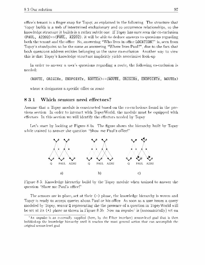
8.3 Our solution 97
o�ce's tenant is a �nger snap for Topsy, as explained in the following. The structure thatTopsy builds is a web of intertwined exclusionary and co-occurrence relationships, so theknowledge structure it builds is a rather subtle one. If Topsy has once seen the co-exclusion(PAUL, A2202)$(PAUL, A2202), it will be able to deduce answers to questions regardingboth the tenant and the o�ce. So, answering \Who lives in o�ce LOCATION?" is, seen fromTopsy's standpoint to be the same as answering \Where lives Paul?", due to the fact thatboth questions address entities belonging to the same co-exclusion. Another way to viewthis is that Topsy's knowledge structure implicitly yields associative look-up.
In order to answer a user's questions regarding a route, the following co-exclusion isneeded:
(ROUTE, ORIGINx, ENDPOINTx, ROUTEx)$(ROUTE, ORIGINx, ENDPOINTx, ROUTEx).
where x designates a speci�c o�ce or route.
8.3.1 Which sensors need e�ectors?
Assume that a Topsy module is constructed based on the co-exclusions found in the pre-vious section. In order to interact with TopsyWorld, the module must be equipped withe�ectors. In this section we will identify the e�ectors needed by Topsy.
Let's start by looking at Figure 8.3a. The �gure shows the hierarchy built by Topsywhile trained to answer the question \Show me Paul's o�ce!".
Q
+- +-
PAUL A2202
+- +-
Q
+- +-
+-
+- +- +-
a) b) c)
+-
PAUL A2202
+-
PAUL A2202
+- +-
Q
Figure 8.3: Knowledge hierarchy build by the Topsy module when trained to answer thequestion \Show me Paul's o�ce!".
The sensors are in place, set at their (-) phase, the knowledge hierarchy is woven andTopsy is ready to accept queries about Paul or his o�ce. As soon as a user issues a querymodeled by Topsy, sensor Q representing the the presence of a question in TopsyWorld willbe set at its (+) phase as shown in Figure 8.3b. Now an impulse4 is (automatically) set on
4An impulse is an externally supplied (here, by the Filter interface) sensor-level goal that is then
bubbled-up the knowledge hierarchy until it reaches the most general action that can accomplish the
original sensor-level goal.

98 Topsy
the sensor (PAUL) as an indication to Topsy that we wish to change the phase of (PAUL).Changing the phase of (PAUL) implies that the sensor(s) seen to co-occur together
with (PAUL) in various co-exclusive relationships, will also change their phase to (+). Theimpulse bubbles up to the highest relevant place in the hierarchy, where an action thentakes a decision about changing the phase of (PAUL), as shown in Figure 8.3c. If there ismore then one meta-sensor that is able to take a decision, one of these is chosen (currently)at random. Depending on the decision taken, a goal (the black arrowhead) is issued anddistributed downwards in the hierarchy. In the end, a number of base-level sensors, infact all sensors pertinent to a co-exclusion that has (PAUL) in it, will receive the goalof changing their phase, as shown by the arrowheads in Figure 8.3c. At this point thesensors marked for change will �re their e�ectors, if there are any. We can see that onlyinformation regarding employees and o�ces is relevant for us, therefore, only these sensorswill be equipped with e�ectors.
8.3.2 Training
Topsy must be trained in order to build its knowledge hierarchy. We envision the trainingscenario depicted in Figure 8.4. Topsy is connected in parallel with an alternative DialogueManager module in order to \tap" the ongoing communication. Both the input and theoutput frames that ow between the blackboard and the Dialogue Manager are relevant forTopsy, as they contain relevant co-occurrences. An input frame is, as a general rule, alwaysfollowed by a corresponding output frame. Thus Topsy will easily model this aspect as aco-exclusion. Figure 8.4 shows how unneeded information from the input or output framesis �ltered out and then the actual co-occurring sensor changes so derived are presented toTopsy.
Topsy will react as follows: If Topsy receives new information (a new co-occurrence),the knowledge hierarchy will be augmented accordingly via the Event Window ; action; meta-sensor process. If, on the other hand, information that has already been seenarrives, Topsy has two possibilities of behaviour:
(1) A plain ignoring of the newly arrived information, as Topsy ensures the \once-is-enough" principle: any co-occurrence (actually, co-exclusion) is implicitly \memo-rized".
(2) Depending on the number of knowledge hierarchy levels that one wishes Topsy to build:
The Base Level only: If only a Base Level is to be constructed, then memorizing againan already seen co-occurrence would not do any good, as this information is redun-dant.
The Base Level and N upper levels (N � 1): Assume for a moment that we'vetrained a Topsy module, and the result of the training is the knowledge hierarchyshown in Figure 8.3a, and that we have instructed Topsy to build a knowledge hierar-chy with two levels (a Base Level and one upper level). Showing the same informationagain will in this case create a meta-sensor on Level 1 as shown in Figure 8.5.

8.3 Our solution 99
Blackboard
Dialogue Manager
Topsy DialogueManager
Topsy Filter
Sensorial Boundary
Figure 8.4: Training a Topsy module: The module is \tapping" the ongoing communicationin the system. As soon as a relevant frame is detected by the Filter, the frame is stripped,and the gist presented to Topsy.
In fact, for each time the same information is presented to Topsy, a new meta-sensoris (can be) created on the next upper level. The knowledge hierarchy's information con-tent remains the same, but now the information repeatedly shown to Topsy is becomingincreasingly re�ned, as explained next.
Assume a Topsy hierarchy built only at the Base Level. Now, if a sensor has been seento take part in two di�erent co-occurrences that do not exclude each other, say (PAUL,
A2-202) and (PAUL, PROFESSOR), then each co-occurrence will be modeled in the knowl-edge hierarchy by distinct meta-sensors situated at the next level, cf. Figure 8.5. Assumethat an impulse is set on (PAUL) and recall that the impulse bubbles up until a meta-sensorcan take a decision. Now that we have two meta-sensors that are able to take the decision,only one of them will be chosen (currently, randomly) by the system. Without a givencontext, this would not create problems because both facts about Paul are true: he livesin A2-202 and he is a professor. If we are in a given context, say we are asking aboutPaul's o�ce, then we would thought be greatly surprised to get information about his job!So, in order to model context and ensure a better answer then a randomly chosen fact,we have to go further up the hierarchy. This can be done by repeatedly presenting thesame information to Topsy while training. In the case at hand, there would presumablybe other similar and relevant meta-sensors which have been co-excluded with those shownin Figure 8.5, which co-exclusions would establish the context for answering the question.
Topsy was trained by presenting it with scripts containing information, as would havebeen generated by the Campus Information System. We have generated the frames as

100 Topsy
+- +-
+- -
+-
Q PAUL A2202
+
Level 2
Level 1
Base Level
Sensorial Boundary
Figure 8.5: When training a Topsy module, repeatedly showing the same information willextend the knowledge hierarchy: for each time the same information is presented to Topsy,a new meta-sensor is (can be) created on the next upper level.
they would be found on CHAMELEON's blackboard. The frames were �ltered and ques-tion/answer pairs, e.g. (QUESTION, PAUL) followed by (PAUL, A2-202) were presented toTopsy. One presentation su�ced to produce the hierarchy in Figure 8.3a. If thereafterTopsy were presented with (QUESTION, PAUL) it would respond with (PAUL, A2-202).The same answer would be given to (QUESTION, A2-202), via the common association of(QUESTION) and (A2-202) with (PAUL).
8.4 Summary
We have described how the Phase Web paradigm, as embodied in the Topsy system,processes example utterances from the Campus Information System domain on the basisof its own experience. By relying on learning, not only is the system self-extending, butwe also avoid having to put in myriads of linguistic and gestural `facts' by hand.
The knowledge structure needed to represent and respond to these queries is quitetrivial, and indeed could be replaced by a simple, traditional database module or somePascal programs. However, we hope we have succeeded in communicating the generalityand power of the learning paradigm, such that it is apparent that more di�cult NLPproblems, requiring processing that is beyond database lookups, can also be handled. Wehope of course to pursue this promise.
One example of this promise that even the present very simple knowledge structurecan answer - quite unintentionally - \Who lives in LOCATION". This re ects the emergentproperties implicit in the Phase Web's unique hierarchical representation. In the samespirit, we note that the co-exclusion relationship also captures `negative information' -what's not the case - that is unavailable to much of traditional NLP (von Hahn 1997).
Finally, we noted very brie y how the problem of integrating information from multiple

8.4 Summary 101
media is solved trivially and directly by registering their co-occurrence.

Chapter 9
Conclusion
We started by introducing IntelliMedia 2000+ and its requirements for an IntelliMediasoftware demonstrator to be used for both research and education purposes. We showedhow a number of candidate applications for a general CHAMELEON software platform tointegrate the processing of spoken dialogue and images were discussed, resulting in an Intel-liMedia WorkBench. We described the architecture and implementation of CHAMELEON:an open, distributed architecture with ten modules glued into a single platform using theDACS communications system. Some of the modules are commercial products (speechrecogniser/synthesiser), others are customised products (e.g. laser), some are our existingsoftware customised (e.g. NLP module, Topsy), and we have developed some from scratch(e.g. gesture recogniser, domain model).
We described the IntelliMedia WorkBench application, a software and physical platformwhere a user can ask for information about things on a physical table. The current domainis a Campus Information System where 2D building plans are placed on the table and thesystem provides information about tenants, rooms and routes and can answer questionslike \Whose o�ce is this?" in real time. We have described the frame semantics, in bothabstract and implemented terms, which is the meaning representation of input and outputinformation constructed on CHAMELEON's blackboard during the course of a dialogueinteraction. A sample dialogue currently processed by the IntelliMedia WorkBench wasshown and a look at the blackboard frame semantics in both theory and practice. Also,we have described in detail how the various modules perform their tasks.
Turning to the requirements of a demonstrator (Chapter 1, Section 1.4.1) it is notedthat CHAMELEON ful�lls all �ve requirements. We have shown that CHAMELEONful�lls the goal of developing a general platform for integration of at least language/visionprocessing which can be used for research but also for student projects as part of theMaster's degree education. Also, the goal of integrating research from four research groupswithin three Departments at the Institute for Electronic Systems has been achieved.

9.1 Relation to other work 103
9.1 Relation to other work
IntelliMedia is an area which has had an upsurge of new interest, particularly since 1994(Mc Kevitt 1994, 1995/1996). Of particular relevance to our work here is other workon developing IntelliMedia platforms and in particular: Situated Arti�cial Communicators
(Rickheit and Wachsmuth 1996), Communicative Humanoids like Gandalf (Th�orisson 1996,1997), AESOPWORLD (Okada 1996, 1997) and MultiModal Interfaces like INTERACT(Waibel et al. 1996).
Situated Arti�cial Communicators (SFB-360) is a collaborative research project at theUniversity of Bielefeld, Germany which focusses on modelling that which a person performswhen with a partner he cooperatively solves a simple assembly task in a given situation.This involves acoustic perception of the spoken word, visual perception of the partnerand the objects and processes involved in the situation, understanding of that perceived,formulation of own utterances (e.g. instructions) and the planning of actions. The domainof application is one where two communicators cooperatively construct an object. Theinstructor has a diagram and instructs the other, the constructor, to carry out actions.The object chosen is a model airplane (Bau�x) to be constructed by a robot from thecomponents of a wooden building kit with instructions from a human. SFB-360 comprisesten subprojects in four thematic �elds: (1) speech and visual perception, (2) perceptionand reference, (3) knowledge and inference and (4) speech-action systems.
SFB-360 is a well rounded project considering all the issues involved in developinga MultiModal platform. SFB-360 includes equivalents of the modules in CHAMELEONalthough there is no learning module competitor to Topsy. What SFB-360 gains in size itmay loose in integration, i.e. it is not clear yet that all the technology from the subprojectshas been �tted together and in particular what exactly the semantic representations passedbetween the modules are. The DACS communications system which we met in Chapters 2and 3 and currently use in CHAMELEON is a useful product from SFB-360.
Gandalf is a communicative humanoid which interacts with users in MultiModal dia-logue through using and interpreting gestures, facial expressions, body language and spokendialogue (Th�orinson 1996, 1997). Gandalf is an application of an architecture called Ymir
which includes perceptual integration of multimodal events, distributed planning and deci-sion making, layered input analysis and motor-control with human-like characteristics andan inherent knowledge of time. Ymir is a broad model of psychosocial dialogue skills thatbridges between multimodal action and multimodal perception in a coherent framework.It is a distributed modular approach to perception, decision and action and can be used tocreate autonomous characters like Gandalf capable of full-duplex multimodal perceptionand action generation. Ymir has a blackboard architecture and includes modules equiva-lent to those in CHAMELEON. However, there is no vision/image processing module sincegesture tracking is done with the use of a data glove and body tracking suit and an eyetracker is used for detecting the user's eye gaze. Also, Ymir has no learning module equiv-alent to Topsy. Ymir's architecture is even more distributed than CHAMELEON's withmany more modules interacting with each other. Also, Ymir's semantic representation ismuch more distributed with smaller chunks of information than our frames being passed

104 Conclusion
between modules.AESOPWORLD is an integrated comprehension and generation system for integration
of vision, language and motion (Okada 1996, 1997). It includes a model of mind consistingof nine domains according to the contents of mental activities and �ve levels along the pro-cess of concept formation. The nine domains are (1) sensor, (2) recognition-understanding,(3) planning-creation, (4) action-expression, (5) actuator, (6) desire-instinct, (7) emotion-character, (8) memory-learning, and (9) language and the �ve levels are: (1) raw data,(2) cognitive features, (3) conceptual features, (4) simple concepts, (5) interconnected-synthesized concepts. Vision and motion are connected and controlled by planning. Thesystem simulates the protagonist or fox of an AESOP fable, \the Fox and the Grapes", andhis mental and physical behaviour are shown by graphic displays, a voice generator, anda music generator which expresses his emotional states. AESOPWORLD has an agent-based distributed architecture and also uses frames as semantic representations. It hasmany modules in common with CHAMELEON although again there is no vision input toAESOPWORLD which uses computer graphics to depict scenes. AESOPWORLD has anextensive planning module but conducts more traditional planning than CHAMELEON'sTopsy.
The INTERACT project (Waibel et al. 1996) involves developing MultiModal HumanComputer Interfaces including the modalities of speech, gesture and pointing, eye-gaze,lip motion and facial expression, handwriting, face recognition and tracking, and soundlocalisation. The main concern is with improving recognition accuracies of modality speci�ccomponent processors as well as developing optimal combinations of multiple input signalsto deduce user intent more reliably in cross-modal speech-acts. Wherever possible learningstrategies which are mostly connectionist and statistical are developed to ensure scalabilityand portability to other application domains. INTERACT also uses a frame representationfor integrated semantics from gesture and speech and partial hypotheses are developed interms of partially �lled frames. The output of the interpreter is obtained by unifying theinformation contained in the partial frames. Although Waibel et al. present good work onmultimodal interfaces it is not clear that they have produced an integrated platform whichcan be used for developing multimodal applications.
In summary, there are a number of platforms under development and most of theminclude two aspects which are characteristic of CHAMELEON: (1) distributed architecture(with blackboard) and (2) semantic representations (as frames). Many include equivalentmodules to those in CHAMELEON, some with additional modules (e.g. emotional music)and some lacking modules (e.g. vision, learning).
9.2 Future work
There are a number of avenues for future work with CHAMELEON. We have provideda sample dialogue to be processed by the next prototype that includes examples of (1)spatial relations and (2) anaphoric reference. Another avenue is to improve the dialoguemanagement and modelling capabilities of CHAMELEON so that it can model the user's

9.2 Future work 105
beliefs and intentions during the course of a dialogue interaction. The blackboard framesemantics will prove very useful here although, at present, the blackboard is simply a �lestore of frames and ideas for a more complex design presented in Chapter 3 have yet to beimplemented. It is hoped that more complex decision taking can be introduced to operateover semantic representations in the dialogue manager or blackboard using, for example, theHUGIN software tool (Jensen (F.) 1996) based on Bayesian Networks (Jensen (F.V.) 1996).The gesture module will be augmented so that it can handle gestures other than pointing.Topsy will be asked to do more complex learning and processing of input/output fromframes. The microphone array has to be integrated into CHAMELEON and set to work. Itwill be used in applications where there are moving speakers and sound source localisationbecomes important but also where there are multiple speakers. All of these ideas willinvolve augmenting the speech, NLP and gesture processing modules. In general, we wantto also focus on the scienti�c goal of testing varying means of module synchronisation andvarying forms of representing semantic and pragmatic information so that they can beoptimised. For example, the blackboard in theory given in Appendix B treats modules as ifthey behave in a completely distributed manner with no single coordinating module whilstthe present implementation of CHAMELEON, as depicted by the blackboard in practice
in Appendix C, has a dialogue manager acting as a central coordinator. It would be ofinterest to implement di�erent behaviours such as these to test the merits of each.
With respect to the IntelliMedia WorkBench application, we can move up to lookingat 3D models rather than 2D plans, which will create more work for vision processing. Acomputer monitor could also display data relevant to the domain such as internet/WWWpages for people or locations referred to. Also, a simulation of the WorkBench could bepresented on the screen, or even projected on a big screen so that more people could seewhat is happening during interaction.
With respect to new applications, we can tackle a whole host (c.f. Chapter 1) such assign language interpretation, remote presence, MultiMedia CAD, and MultiMedia virtualreality. Application areas of particular interest are Mobile computing, Intelligent Video-Conferencing and IntelliMedia information retrieval.
9.2.1 Mobile computing
The mobile computing aspects of IntelliMedia are particularly relevant. This will enableusers to interact with perceptual speech and image data at remote sites and where that datacan be integrated and processed at some central source with the possibility of results beingrelayed back to the user. The increase in bandwidth for wired and wireless networks andthe proliferation of hand-held devices (e.g. NOKIA 9000 communicator1) and computers(Bruegge and Bennington 1996, Rudnicky et al. 1996, Smailagic and Siewiorek 1996)brings this possibility even closer even with today's separation of information interchangeinto di�erent data and voice channels. Future introduction of information exchange over acommon data/voice channel is expected to further extend mobile computing, and we will
1NOKIA 9000 communicator is a trademark of NOKIA.

106 Conclusion
undoubtedly see the emergence of totally new applications with impressive performance.
Applications of mobile IntelliMedia are numerous including data fusion during emer-gencies, remote maintenance, remote medical assistance, distance teaching and internetweb browsing. One can imagine mobile o�ces where one can transfer money from/to yourbank account, order goods and tickets even while car cruising. The possibility of control-ling robots through mobile communications is gaining momentum (Uhlin and Johansson1996) and will continue to ourish. There are also applications within virtual reality anda feel for these is given in IEEE Spectrum (1997).
The large recent proliferation of conferences on wireless technologies, mobile MultiMe-dia, computing and networking indicates the surge of interest in this area. There has beenrapid convergence of computing and telecommunications technologies in the past few years(IEEE Spectrum 1996). Although there has been great interest in the communication oftraditional MultiMedia over wired and wireless networks there has been little developmentin the area of Intelligent MultiMedia which requires greater bandwidth. For IntelliMediawe need much larger bandwidths, like several 100's of Mb/s, and it is necessary to go tohigher carrier frequencies in the millimeter range, where propagation coverage is more lim-ited, and where there are some economic constraints for the moment. There is no doubt,however, that in the beginning of the next century we shall see a major bandwidth ex-pansion for mobility, in the beginning in limited areas. The bandwidths mentioned aboveshould be su�cient for the �rst generation systems (Roehle 1997).
Wireless mobile computing aspects of our Campus Information System become evidentif we consider the user moving away from the WorkBench and walking in the buildingrepresented by the 2D plans with a wearable computer (Bruegge and Bennington 1996,Rudnicky et al. 1996, Smailagic and Siewiorek 1996), head-mounted display and even dif-ferential global positioning system (D-GPS). Here the system will give directions when theuser is moving in the building complex. The wearable computer is online and communicateswith the host IntelliMedia Workbench.
9.2.2 IntelliMedia VideoConferencing
Another area where CHAMELEON could be applied is Intelligent VideoConferencingwhere multiple users can direct cameras through spoken dialogue and gesture. As men-tioned in Chapter 1 a miniature version of this idea has already been completed as astudent project (Bakman et al. 1997a). Also, such techniques could even be applied inthe IntelliMedia WorkBench application where for example multiple speakers (architects)could be planning building and city layout. Other more complex tasks for IntelliMediainclude person identi�cation from images and speech.
9.2.3 IntelliMedia information retrieval
SuperinformationhighwayS which have massive stores of information in MultiMedia formsrequire more intelligent means of information retrieval, where \less" means \more", through

9.2 Future work 107
spoken dialogue and other methods. This is and will be a major application area ofIntelliMedia (Maybury 1997).
Intelligent MultiMedia will be important in the future of international computing andmedia development and IntelliMedia 2000+ at Aalborg University, Denmark brings to-gether the necessary ingredients from research, teaching and links to industry to enableits successful implementation. Particularly, we have research groups in spoken dialogueprocessing and image processing which are the necessary features of this technology. Wehave a strong commitment to investigate how CHAMELEON can be used for teaching andtraining. Our CHAMELEON platform and IntelliMedia WorkBench application are idealfor testing integrated signal and symbol processing of language and vision for the futureof SuperinformationhighwayS.

Acknowledgements
We take this opportunity to acknowledge funded support from the Faculty of Science andTechnology (FaST), Aalborg University, Denmark and from the European Union (EU)under the ESPRIT (OPEN-LTR) Project 24 493. Paul Mc Kevitt would also like to ac-knowledge the British Engineering and Physical Sciences Research Council (EPSRC) fortheir generous funded support under grant B/94/AF/1833 for the Integration of NaturalLanguage, Speech and Vision Processing (Advanced Fellow). We would like to acknowledgethe Steering Committee for IntelliMedia 2000+: Stig K. Andersen (head, MI), FlemmingK. Fink (ESN Masters' coordinator), Flemming B. Frederiksen (head, Institute-8), ErikGranum (head, LIA) and Arne Skou (head, CS), the director of CPK, J�rgen Bach Ander-sen, Niels Maarbjerg Olesen (deputy Dean) and Finn Kj�rsdam (Dean) from the Facultyof Science and Technology, for their invaluable advice and support. Many of them have alsoread and commented on an earlier draft of this report. We also had stimulating discussionswith Anders B�kgaard and Bo Nygaard Bai.
A number of students have done excellent work for CHAMELEON including Lau Bak-man and Mads Blidegn (KOM) who set up the laser software drivers, J�rgen B. Nielsen(KOM) who evaluated and downloaded DACS from the University of Bielefeld, and NicolaeTuns and Thomas Dorf Nielsen (CS) who provided the demo-implementation and initialdescription of the Topsy module.
Helge Vad (CS) got the Topsy platform running and Bo Nygaard Bai (CPK) helped withspeci�cations for the laser drivers and general systems support. Claus B. Madsen (LIA)participated in discussing the possible demonstrator applications described in Chapter 1and also read and commented on an earlier draft of this report. Ipke Wachsmuth (Univer-sity of Bielefeld, Germany) and Kris Th�orinsson (LEGO digital, Denmark) are thanked fortheir useful suggestions on IntelliMedia 2000+ and CHAMELEON while visiting. Thanksto Henrik Benner and Karsten Thygesen for systems and technical support and to JohnnaE. Nonboe (graphics, KOM) for help with drawing and tidying some of the pictures herein.

Appendix A
Size of camera lens
The camera is a JAI 2040 colour 1/2" CCD (Charged Coupled Device) camera with auto-gain (see JAI 1996). Here, we show how the size of the camera lens (6mm) is chosen. Tounderstand how the size of the lens can be calculated look at Figure A.1 which shows apinhole model (Gonzales and Woods 1993) of the camera and the WorkBench table.
�����������������������������������������������������������������������������������������������������������������������������������������������������������������������������������������������������������������������������������������������������������������������������������������������������������������������������������������������������������������������������������������������������������������������������������������������������������������������������������������������������������������������������������������������������������������������������������������������������������������������������������������������������������������������������������������������������������������������������������������������������������������������������������������������������������������������������������������������������������������������������������������������������������������������������������������������������������������������������������������������������������������������������
�����������������������������������������������������������������������������������������������������������������������������������������������������������������������������������������������������������������������������������������������������������������������������������������������������������������������������������������������������������������������������������������������������������������������������������������������������������������������������������������������������������������������������������������������������������������������������������������������������������������������������������������������������������������������������������������������������������������������������������������������������������������������������������������������������������������������������������������������������������������������������������������������������������������������������������������������������������������������������������������������������������������������������
b
h
f
a
TABLE
CCD CHIP
LENS CENTER
Figure A.1: A pinhole model of camera and WorkBench
The CCD (Charged Coupled Device) chip is shown at the top of the �gure and this iswhere the image (light) is captured. How large an area that can be captured, depends on

110 Size of camera lens
the size of the chip a, the focal length, f , and the distance from the camera to the table,h. The focal length is the distance from the CCD chip to the center of the lens and this iswhat is referred to as the size of the lens. The smaller this distance is, the larger an areacan be captured. But as f decreases, the resolution also decreases. So f should not bechosen too small.
Due to the relations between the triangles in �gure A.1 the following relations can bestated.
a=2
f=
b=2
h, (A.1)
a
f=
b
h, (A.2)
f =a � hb
, (A.3)
b =a � hf
(A.4)
The maximum size of the lens can now be calculated. Since neither the CCD chip orthe table are squared, two cases must be evaluated; one for the x-direction and one for they-direction. To do so, look at �gure A.2 where the relation between the CCD chip and thetable is shown.
Cx
Cy
X
Y
TABLECCD CHIP
Figure A.2: Parameters de�ning CCD chip and table
First the calculation is done in the x-direction where the parameter of the CCD chipis Cx = 0:66cm and the parameter of the table is x = 185cm. Using equation A.3 yieldsfx = 9:3mm Next the calculation is done in the y-direction where the parameter of theCCD chip is Cy = 0:44cm and the parameter of the table is y = 120cm. Using equationA.3 yields fy = 9:5mm This means that the lens should be smaller than 9:3mm. A normallens is very unlinear in the outer regions and therefore it is normally a good idea to chosethe lens a bit smaller than required to avoid this problem. Also, there should be room for

Size of camera lens 111
movements of the table without forced the camera to be moved. Therefore, a 6mm lens ischosen. When inserting this choice in equation A.4 the new workspace is 286 � 191cm.

Appendix B
Blackboard in theory
Here we derive all the frames appearing on the blackboard for two examples: (1) \Point toHanne's o�ce" (instruction), and (2) \Whose o�ce is this?" + [pointing] (exophoric/deicticreference).
There are input, output and integration frames (F-in, F-out, F-int), input and outputgestures (G-in, G-out) and input and output utterances (U-in, U-out). Input modules areSPEECH-RECOGNISER (U-in) and GESTURE (G-in). Output modules are LASER (G-out) and SPEECH-SYNTHESIZER (U-out). Most modules give and take frames to/fromthe blackboard database and process them (F-int).
We choose to have modules interacting in a completely distributed manner with nosingle coordinating module. The actual present implementation of CHAMELEON hasa dialogue manager which acts as a central coordinator. Although we show the variousmodules acting in a given sequence here, module processing and frames may not necessarilyrun in this order. The frames given are placed on the blackboard as they are producedand processed.
Example 1: giving an instruction
USER(U-in): Point to Hanne's o�ce
PROCESSING(1):
SPEECH-RECOGNISER:
(1) wakes up when it detects registering of U-in
(2) maps U-in into F-in
(3) places and registers F-in on blackboard:
FRAME(F-in)(1):
[SPEECH-RECOGNISER
UTTERANCE: (Point to Hanne's o�ce)
INTENTION: instruction!

Blackboard in theory 113
TIME: timestamp]
PROCESSING(2):
NLP:
(1) wakes up when it detects registering of F-in
(2) maps F-in into F-int
(3) places and registers F-int on blackboard:
FRAME(F-int)(1):
[NLP
INTENTION: instruction! (pointing)
LOCATION: o�ce (tenant Hanne) (coordinates (X, Y))
TIME: timestamp]
PROCESSING(3):
DOMAIN-MODEL:
(1) wakes up when it detects registering of F-int
(2) reads F-int and sees its from NLP
(3) produces updated F-int (coordinates)
(4) places and registers updated F-int on blackboard:
FRAME(F-int)(2):
[DOMAIN-MODEL
INTENTION: instruction! (pointing)
LOCATION: o�ce (owner Hanne) (coordinates (5, 2))
TIME: timestamp]
PROCESSING(4):
NLP:
(1) wakes up when it detects registering of F-int
(2) reads F-int and sees it's from DOMAIN-MODEL
(3) produces updated F-int (intention + utterance)
(4) places and registers updated F-int on blackboard:
FRAME(F-int)(3):
[NLP
INTENTION: description (pointing)
LOCATION: o�ce (owner Hanne) (coordinates (5, 2))
UTTERANCE: (This is Hanne's o�ce)
TIME: timestamp]
PROCESSING(5):
LASER:
(1) wakes up when it detects registering of F-int
(2) reads F-int and sees it's from DOMAIN-MODEL

114 Blackboard in theory
(3) produces F-out (pruning + registering)
(4) places and registers F-out on blackboard:
FRAME(F-out)(1):
[LASER
INTENTION: description (pointing)
LOCATION: coordinates (5, 2)
TIME: timestamp]
PROCESSING(6):
SPEECH-SYNTHESIZER:
(1) wakes up when it detects registering of F-int
(2) reads F-int and sees it's from NLP
(3) produces F-out (pruning + registering)
places and registers F-out on blackboard:
FRAME(F-out)(2):
[SPEECH-SYNTHESIZER
INTENTION: description
UTTERANCE: (This is Hanne's o�ce)
TIME: timestamp]
PROCESSING(7):
DIALOGUE MANAGER:
(1) wakes up when it detects registering of F-out and F-out
(2) reads F-out and F-out and sees they are from
LASER and SPEECH-SYNTHESIZER
(3) dials and �res LASER and SPEECH-SYNTHESIZER
in a rhythmic way (synchronized)
(1) LASER reads its own F-out and �res G-out
(2) SPEECH-SYNTHESIZER reads its own F-out and �res U-out
CHAMELEON(G-out): [points]
CHAMELEON(U-out): This is Hanne's o�ce.
Example 2: deictic reference
USER(G-in,U-in): [points]
Whose o�ce is this?
PROCESSING(1):
SPEECH-RECOGNISER:
(1) wakes up when it detects registering of U-in
(2) maps U-in into F-in

Blackboard in theory 115
(3) places and registers F-in on blackboard
FRAME(F-in)(1):
[SPEECH-RECOGNISER
UTTERANCE: (Whose o�ce is this ?)
INTENTION: query?
TIME: timestamp]
PROCESSING(2):
NLP:
(1) wakes up when it detects registering of F-in
(2) maps F-in into F-int
(3) places and registers F-int on blackboard:
FRAME(F-int)(1):
[NLP
INTENTION: query? (who)
LOCATION: o�ce (tenant person) (coordinates (X, Y))
REFERENT: this
TIME: timestamp]
PROCESSING(3):
DOMAIN-MODEL:
(1) wakes up when it detects registering of F-int
(2) reads F-int and sees its from NLP
(3) cannot update F-int as doesn't have a name or coordinates
(4) goes back to sleep
PROCESSING(4):
GESTURE:
(1) wakes up when it detects registering of G-in
(2) maps G-in into F-in
(3) places and registers F-in on blackboard
FRAME(F-in)(2):
[GESTURE
GESTURE: coordinates (3, 2)
INTENTION: pointing
TIME: timestamp]
PROCESSING(5):
DIALOGUE MANAGER:
(1) wakes up when it detects registering of F-in(1) and F-in(2)
(2) reads F-in(1) and F-in(2) and
sees they are from SPEECH-RECOGNISER and GESTURE

116 Blackboard in theory
that they have same/close timestamp,
there is a query? (with referent) + pointing,
in a rhythmic way (synchronized)
(3) dials and �res NLP to read GESTURE
PROCESSING(6):
NLP:
(1) woken up by DIALOGUE-MANAGER and reads F-in(2)
(2) sees F-in(2) is from GESTURE
(3) determines referent of ``this" to be (coordinates)
(4) produces updated F-int (coordinates)
(5) places and registers updated F-int on blackboard:
FRAME(F-int)(2):
[NLP
INTENTION: query? (who)
LOCATION: o�ce (tenant person) (coordinates (3, 2))
REFERENT: this
TIME: timestamp]
PROCESSING(7):
DOMAIN-MODEL:
(1) wakes up when it detects registering of F-int
(2) reads F-int and sees its from NLP
(3) produces updated F-int (tenant)
(4) places and registers updated F-int on blackboard:
FRAME(F-int)(3):
[NLP
INTENTION: query? (who)
LOCATION: o�ce (tenant Ipke) (coordinates (3, 2))
REFERENT: this
TIME: timestamp]
PROCESSING(8):
NLP:
(1) wakes up when it detects registering of F-int
(2) reads F-int and sees it's from DOMAIN-MODEL
(3) produces updated F-int (intention + utterance)
(4) places and registers updated F-int on blackboard:
FRAME(F-int)(4):
[NLP
INTENTION: declarative (who)
LOCATION: o�ce (tenant Ipke) (coordinates (3, 2))

Blackboard in theory 117
REFERENT: this
UTTERANCE: (This is Ipke's o�ce)
TIME: timestamp]
PROCESSING(9):
LASER:
(1) wakes up when it detects registering of F-int
(2) reads F-int and sees it's from DOMAIN-MODEL
(3) produces F-out (pruning + registering)
(4) places and registers F-out on blackboard:
FRAME(F-out)(1):
[LASER
INTENTION: description (pointing)
LOCATION: coordinates (3, 2)
TIME: timestamp]
PROCESSING(10):
SPEECH-SYNTHESIZER:
(1) wakes up when it detects registering of F-int
(2) reads F-int and sees it's from NLP
(3) produces F-out (pruning + registering)
places and registers F-out on blackboard:
FRAME(F-out)(2):
[SPEECH-SYNTHESIZER
INTENTION: description
UTTERANCE: (This is Ipke's o�ce)
TIME: timestamp]
PROCESSING(11):
DIALOGUE-MANAGER:
(1) wakes up when it detects registering of F-out(1) and F-out(2)
(2) reads F-out(1) and F-out(2) and sees they are from
LASER and SPEECH-SYNTHESIZER
(3) dials and �res LASER and SPEECH-SYNTHESIZER
in a rhythmic way (synchronized)
(1) LASER reads G-out and �res G-out
(2) SPEECH-SYNTHESIZER reads U-out and �res U-out
CHAMELEON(G-out): [points]
CHAMELEON(U-out): This is Ipke's o�ce.

Appendix C
Blackboard in practice
Here we show the complete blackboard (with all frames) as produced exactly byCHAMELEON for the example dialogue given in Chapter 2, Section 2.2. Note that unlikethe blackboard in theory above (Appendix B) the present implementation of CHAMELEONhas a dialogue manager which acts as a central coordinator.
Received: nlp(intention(instruction(pointing)),location(person(tb),type(office)),
time(889524794))
which is passed on to dialog_manager
Received: dialog_manager(output(laser(point(coordinates(249,623))),
speech_synthesizer(utterance("This is Toms office"))))
Calling laser: laser(point(coordinates(249,623)))
Calling speech_synthesizer: speech_synthesizer(utterance("This is Toms office"))
Received: nlp(intention(instruction(pointing)),location(person(tbm),type(office)),
time(889524818))
which is passed on to dialog_manager
Received: dialog_manager(output(laser(point(coordinates(278,623))),
speech_synthesizer(utterance("This is Thomass office"))))
Calling laser: laser(point(coordinates(278,623)))
Calling speech_synthesizer: speech_synthesizer(utterance("This is Thomass office"))
Received: nlp(intention(query(where)),location(place(a2_221)),
time(889524831))
which is passed on to dialog_manager
Received: dialog_manager(output(laser(point(coordinates(132,500))),
speech_synthesizer(utterance("computer room is here"))))
Calling laser: laser(point(coordinates(132,500)))
Calling speech_synthesizer: speech_synthesizer(utterance("computer room is here"))

Blackboard in practice 119
Received: nlp(intention(query(who)),location(this($Deixis),type(office)),
time(889524864))
which is passed on to dialog_manager
Received: dialog_manager(output(laser(point(coordinates(658,546))),
speech_synthesizer(utterance("This is not an office, this is instrument repair"))))
Calling laser: laser(point(coordinates(658,546)))
Calling speech_synthesizer:
speech_synthesizer(utterance("This is not an office, this is instrument repair"))
Received: nlp(intention(query(who)),location(this($Deixis),type(office)),
time(889524885))
which is passed on to dialog_manager
Received: dialog_manager(output(laser(point(coordinates(223,568))),
speech_synthesizer(utterance("This is Pauls office"))))
Calling laser: laser(point(coordinates(223,568)))
Calling speech_synthesizer: speech_synthesizer(utterance("This is Pauls office"))
Received: nlp(intention(instruction(show_route)),source(location(person(lbl),
type(office))),
destination(location(person(hg),type(office))),time(889524919))
which is passed on to dialog_manager
Received: dialog_manager(output(laser(route(coordinates(278,585,278,603,249,
603,220,603,197,603,197,623))),
speech_synthesizer(
utterance("This is the route from Lars Bos office to Hannes office"))))
Calling laser:
laser(route(coordinates(278,585,278,603,249,603,220,603,197,603,197,623)))
Calling speech_synthesizer:
speech_synthesizer(
utterance("This is the route from Lars Bos office to Hannes office"))
Received: nlp(intention(instruction(show_route)),source(location(person(pmck),
type(office))),destination(location(place(a2_105))),time(889524942))
which is passed on to dialog_manager
Received: dialog_manager(output(laser(route(coordinates(174,453,153,453,153,
481,153,500,153,510,153,540,153,569,153,599,153,603,184,603,197,603,220,603,
249,603,278,603,307,603,330,603,330,655,354,655,911,655,884,655,884,603,810,
603,759,603,717,603,717,570,696,570))),
speech_synthesizer(
utterance("This is the route from Pauls office to instrument repair"))))

120 Blackboard in practice
Calling laser: laser(route(coordinates(174,453,153,453,153,481,153,500,153,
510,153,540,153,569,153,599,153,603,184,603,197,603,220,603,249,603,278,603,
307,603,330,603,330,655,354,655,911,655,884,655,884,603,810,603,759,603,717,
603,717,570,696,570)))
Calling speech_synthesizer:
speech_synthesizer(
utterance("This is the route from Pauls office to instrument repair"))
Received: nlp(intention(instruction(pointing)),location(person(pd),type(office)),
time(889524958))
which is passed on to dialog_manager
Received: dialog_manager(output(laser(point(coordinates(220,585))),
speech_synthesizer(utterance("This is Pauls office"))))

Appendix D
Syntax of frames
The following BNF grammar de�nes a predicate-argument syntax for the form of messages(frames) appearing on CHAMELEON's implemented blackboard.
FRAME ::= PREDICATE
PREDICATE ::= identifier(ARGUMENTS)
ARGUMENTS ::= ARGUMENT
| ARGUMENTS, ARGUMENT
ARGUMENT ::= CONSTANT
| VARIABLE
| PREDICATE
CONSTANT ::= identifier
| integer
| string
VARIABLE ::= $identifier
FRAME acts as start symbol, CAPITAL symbols are non-terminals, and terminals arelower-case or one of the four symbols ( ) , and $. An identi�er starts with a letter thatcan be followed by any number of letters, digits or , an integer consists of a sequenceof digits and a string is anything delimited by two "'s. Thus the alphabet consists of theletters, the digits and the symbols ( ) , and $. A parser has been written in C whichcan parse the frames using this BNF de�nition.

Appendix E
Camera calibration
Here, a detailed description of camera calibration for CHAMELEON is given.
E.1 A homogeneous representation
Intuitively, the calibration can be explained as �nding the translation and rotation di�er-ences between the 2D plan coordinate system and the camera coordinate system. Whendealing with relations between an image and a world coordinate system, a transformationequation between the two can be de�nes as
ch = A �wh (E.1)
where ch holds information about the image point (xi; yi) and wh holds informationabout the world point (Xw; Yw; Zw). A is the transformation matrix which maps from onecoordinate system to the other. It holds information about the rotation, translation andperspective transformation through the camera lens (Gonzalez and Woods 1993).
Homogeneous coordinates are used to represent both image points and world points.This is done in order to make A a square matrix facilitating calculations. However, thismeans that the transformation is not done directly between the image point and the worldpoint, but instead between the homogeneous world point and the homogeneous and per-spective transformed image point (Gonzalez and Woods 1993) as shown here,
2664ch1ch2ch3ch4
3775 =
2664a11 a12 a13 a14a21 a22 a23 a24a31 a32 a33 a34a41 a42 a43 a44
3775 �2664kXw
kYwkZw
k
3775
where,

E.2 Calculating coe�cients 123
ch1
ch4= xi (E.2)
ch2
ch4= yi (E.3)
Substituting E.2 and E.3 into the homogeneous equation system and expanding thematrix product for the �rst, second and third row with k = 1 yields,
xich4 = a11Xw + a12Yw + a13Zw + a14 (E.4)
yich4 = a21Xw + a22Yw + a23Zw + a24 (E.5)
ch4 = a41Xw + a42Yw + a43Zw + a44 (E.6)
The world coordinate system is de�ned to have its X-Y-plane parallel to the physical2D plan and Zw = 0 for all world points located on the 2D plan. Using this decision andsubstitute E.6 into E.4 and E.5 respectively yields,
a11Xw + a12Yw + a14 � xia41Xw � xia42Yw � xia44 = 0 (E.7)
a21Xw + a22Yw + a24 � yia41Xw � yia42Yw � yia44 = 0 (E.8)
E.2 Calculating coe�cients
The coe�cients inA (homogeneous transformation) need to be calculated before the actualmapping function between the two coordinate systems can be derived. The problem is nowto solve the two equations; E.7 and E.8 with respect to the coe�cients, axy. A world pointand the image point this is mapped into can easily be obtained, but it is still not possibleto solve the equations directly since the problem is underdetermined, two equations andnine unknowns. The problem is solved by adding more information without increasing thenumber of unknowns. To avoid the zero-solution it is chosen to �x one of the coe�cients,a24 = �1. Now three other pairs of equations like E.7 and E.8 are set up with di�erentvalues of (xi; yi) and (Xw; Yw)

124 Camera calibration
a11Xw1 + a12Yw1 + a14 � xi1a41Xw1 � xi1a42Yw1 � xi1a44 = 0
a21Xw1 + a22Yw1 + a24 � yi1a41Xw1 � yi1a42Yw1 � yi1a44 = 0
a11Xw2 + a12Yw2 + a14 � xi2a41Xw2 � xi2a42Yw2 � xi2a44 = 0
a21Xw2 + a22Yw2 + a24 � yi2a41Xw2 � yi2a42Yw2 � yi2a44 = 0
a11Xw3 + a12Yw3 + a14 � xi3a41Xw3 � xi3a42Yw3 � xi3a44 = 0
a21Xw3 + a22Yw3 + a24 � yi3a41Xw3 � yi3a42Yw3 � yi3a44 = 0
a11Xw4 + a12Yw4 + a14 � xi4a41Xw4 � xi4a42Yw4 � xi4a44 = 0
a21Xw4 + a22Yw4 + a24 � yi4a41Xw4 � yi4a42Yw4 � yi4a44 = 0
The new indexes indicate coherency, meaning that (Xw1; Yw1) is mapped into the imagecoordinate system as (xi1; yi1). These four coherent pairs can be measured and thereforethe problem is now solvable since it consists of eight equations with eight unknowns. Theequations are rearranged into a linear system u = H � b
266666666664
01010101
377777777775=
266666666664
Xw1 Yw1 0 0 �Xw1xi1 �Yw1xi1 �xi1 10 0 Xw1 Yw1 �Xw1yi1 �Yw1yi1 �yi1 0Xw2 Yw2 0 0 �Xw2xi2 �Yw2xi2 �xi2 10 0 Xw2 Yw2 �Xw2yi2 �Yw2yi2 �yi2 0Xw3 Yw3 0 0 �Xw3xi3 �Yw3xi3 �xi3 10 0 Xw3 Yw3 �Xw3yi3 �Yw3yi3 �yi3 0Xw4 Yw4 0 0 �Xw4xi4 �Yw4xi4 �xi4 10 0 Xw4 Yw4 �Xw4yi4 �Yw4yi4 �yi4 0
377777777775�
266666666664
a11a12a21a22a41a42a44a14
377777777775
The coe�cients of A can now be found as
b = H�1 � u (E.9)
Many numerical techniques exist for �nding an optimal solution for b. It is chosen touse the Singular Value Decomposition method since this is a stable method which is easyto implement (Press et al. 1990).
E.3 Finding the corresponding pairs
Before equation E.9 can be solved the four pairs of corresponding image points and worldpoints need to be found. As already mentioned the world coordinate system is chosen to

E.3 Finding the corresponding pairs 125
be located on top of the 2D plan. The origin of the world coordinate system is placed inthe upper left corner of the 2D plan having the X and Y-axis following the edges of the2D plan and the Z-axis equal to zero in the plane spanned by the 2D plan. In this way theworld coordinate system is de�ned by the location and orientation of the 2D plan.
The four image points should be easily located landmarks in order to make the calibra-tion robust. It is chosen to use the corners of the plan since they are present anyway. Thisalso means that no arti�cial markers need be introduced. The position of the four cornersis measured (using a ruler) in the world coordinate system. Since the 2D plan de�nesthe world coordinate system and since the plan is a rigid object, these four measurementsonly need to be done once and then the results can be reused every time the camera iscalibrated.
E.3.1 Finding the image points
The camera will not be moved very often but the 2D plan might. Therefore the calibrationshould be done automatically. The algorithm for �nding the four corner points is designedto be independent of how the 2D plan is oriented on the table, as long as it is not enteringarea 2. Two versions of this algorithm are implemented, each having a di�erent assumptionof how the 2D plan is oriented. The algorithms are processed in parallel and the one whichcomes up with the best result will determine the location of the four corner points. Thetwo orientation assumptions for the two versions are shown in Figure E.1.
CB
AREA 2
2D MODEL 2D MODEL
AREA 2
A
2D MODEL
AREA 2
Figure E.1: A) �rst assumption; B) second assumption; C) in-between situation
The �rst version of the algorithm assumes that the 2D plan is located as shown inFigure E.1.a, while the second version assumes Figure E.1.b. The closer the 2D plan isto one of the �gures the more unambiguous the result will be. When the 2D plan isoriented in between the two assumptions, as shown in Figure E.1.c, it is random as towhich version delivers the best result. However, the results should still be correct, but theuncertainty grows the further the orientation of the 2D plan gets from the situations shownin Figure E.1.a and E.1.b.
Independent of which version of the algorithm is used, the method is the same. Eachcorner is found separately but using the same technique which will be explained for onecorner of assumption a. First a search is carried out towards the corner as shown inFigure E.2.a.

126 Camera calibration
2D MODEL
A
2D MODEL
B
THE CORNER POINT
C
SEARCH-LINESEARCH-
LINESSEARCH-
LINES
Figure E.2: A) �rst search for one corner; B) second search for one corner; C) close up ofcorner and found corner point
The search is done in lines perpendicular to the assumed orientation of the 2D plan andstops when a prede�ned number of \white" pixels (compared to the \dark" background)are found in one line. The idea is to make this prede�ned number so high that the in uenceof noise is removed, meaning that this search does not stop until it is absolutely sure thatit has found the 2D plan and not just some random noise. Hereafter, the second search asshown in Figure E.2.b, is carried out. It also searches in lines but in the opposite direction.It stops when no more \white" pixels can be found in a line and concludes that the cornermust be in the previous search line. The actual corner point is found as the average positionof all \white" pixels in this line.
It might come as a surprise to the reader that a corner has to be found in this way.The reason for this can be seen in Figure E.2.c where a close up of a corner is shown. Theproblem is that a corner is far from well de�ned when you look at it on pixel level andhence some kind of averaging must be done.
E.3.2 Evaluation of corner points
Both versions of the algorithm come up with four image points which are believed to bethe correct corner points. But how do we �gure out which set of points is the correct one?For each version of the algorithm the following is done. The distances between every pointis calculated yielding six numbers which are sorted according to their values
D = [d1 d2 d3 d4 d5 d6]T (E.10)
where d6 is the highest value.If the 2D plan was a perfect rectangle and the camera/framegrabber was ideal then
d1 = d2, d3 = d4 and d5 = d6. Even though nothing is ideal the following equation, , willstill give a rather good indication of how good the data matches a rectangle
= jd1 � d2j+ jd3 � d4j+ jd5 � d6j (E.11)

E.4 From image points to world points 127
After implementing this it was noticed that can be rather small without representingthe 2D model (or a rectangle) if the corner candidates are found in certain unfavourablepositions, for example, in the same position. This problem is solved by using knowledgeabout the shape of the 2D plan. Since it is a rectangle d1 < d6. Equation E.11 is nowexpanded into
=
(jd1 � d2j+ jd3 � d4j+ jd5 � d6j if d1 � t < d6
�42 otherwise(E.12)
where t is found imperial to 1:3. For each version of the algorithm is calculated andthe one with the lowest positive value is the version which has found the correct cornerpoints.
E.4 From image points to world points
In this section the two equations which are used to map an image point (xi; yi) into a worldpoint (Xw; Yw) are derived. To make the calculations easier to follow, equation E.7 and E.8are rewritten
Xw(a11 � xia41) + Yw(a12 � xia42) + (a14 � xia44) = 0) (E.13)
Xw�x + Yw�x + x = 0 (E.14)
Xw(a21 � yia41) + Yw(a22 � yia42) + (a24 � yia44) = 0) (E.15)
Xw�y + Yw�y + y = 0 (E.16)
Isolating Xw in E.14 yields
Xw =�Yw�x � x
�x(E.17)
Inserting Xw in E.16 yields
0 = (�Yw�x � x
�x) � �y + Yw�y + y ) (E.18)
0 = Yw � (�y ��x�y
�x) + y �
x�y
�x) (E.19)
Yw =
x�y
�x� y
�y � �x�y
�x
) (E.20)
Yw = x�y � y�x
�y�x � �x�y(E.21)

128 Camera calibration
Xw can now be found as
Xw =�Yw�x � x
�x)
Xw =�( x�y� y�x
�y�x��x�y) � �x � x
�x)
Xw =��x � ( x�y � y�x)� x � (�y�x � �x�y)
�x � (�y�x � �x�y))
Xw =��x x�y + �x y�x � x�y�x + x�x�y
�x�y�x � �x�x�y
E.5 From world points to image points
In this section the two equations which are used to map a world point (Xw; Yw) intoan image point (xi; yi) are derived. The image point is simply found by isolating xi inequation E.7 and yi in equation E.8
0 = �a11Xw � a12Yw � a14 + xia41Xw + xia42Yw + xia44 )0 = xi(a41Xw + a42Yw + a44)� (a11Xw + a12Yw + a14))xi =
a11Xw + a12Yw + a14
a41Xw + a42Yw + a44
0 = �a21Xw � a22Yw � a24 + yia41Xw + yia42Yw + yia44 )0 = yi(a41Xw + a42Yw + a44)� (a21Xw + a22Yw + a24))yi =
a21Xw + a22Yw + a24
a41Xw + a42Yw + a44
E.6 Summary
In this appendix camera calibration for CHAMELEON and the IntelliMedia WorkBenchhave been described. The purpose of the calibration is to �nd a transformation betweena world point and an image point. A homogeneous transformation system is set up wherefour world points and the corresponding image points are needed. The world points arede�ned to be the corners of the plan which can be measured directly on the 2D plan. Thecorresponding image points are found automatically using a three level search method.When the homogeneous transformation matrix is calculated, the actual transformationbetween a world point and an image point (and visa versa) are derived.
The system is now self-calibrating with respect to the camera and the 2D plan. Sincethe 2D plan (or the table it is located on) is often moved, the calibration is done every

E.6 Summary 129
time the tracking module is started up and last for about 5 seconds. Of course nothingcan interact with the plan in this period.

Appendix F
NLP grammar
Here, we give the axioms, lexical, syntactic and semantic rules for the NLP grammar.
%%%%%%%%%%%%%%%%%%%%%%%%%%%%%%%%%%%%%%%%%%%%%
%% MMUI.APS %%
%% Multimedia Multimodal User Interface %%
%% augmented phrase structure grammar %%
%% %%
%% Version: 1.3 %%
%% Date : Jan 98 %%
%% Version History: %%
%% v. 0.0 based on pure syntactic parsing and percolation %%
%% of semantic values. Output a simple feature set %%
%% equivalent to the format planned for REWARD. %%
%% Designers: bakman & blidegn. %%
%% v. 1.0 based on syntactic parsing and semantic mapping, %%
%% Output equivalent to the "semantic represen- %%
%% tations" defined in the AB-platform und used in %%
%% the P1 flight ticket reservation system. %%
%% Designer: tb %%
%% v. 1.1 based on syntactic parsing and mapping into struc- %%
%% equivalent to the predicate-argument BNF defined %%
%% for the MMUI. APS. The method utilizes new fasci- %%
%% lities built into the NL parser (dynamic genera- %%
%% tion of semantic trees as opposed to the static %%
%% structures of version 1.0). %%
%% v. 1.2 added persons and places %%
%% v. 1.3 The syntax of semantic mapping rules has been %%
%% slightly modified (glue nodes) %%
%% %%
%% Tom Broendsted %%
%% %%
%%%%%%%%%%%%%%%%%%%%%%%%%%%%%%%%%%%%%%%%%%%

NLP grammar 131
%%%%%%%%%%%%%%%%%%%%%%%%%%%%%%%%%%%%%%%%%%%
%% AXIOMS %%
%%%%%%%%%%%%%%%%%%%%%%%%%%%%%%%%%%%%%%%%%%%
%%## English
axiom1 = [{cat=s}].
%%%%%%%%%%%%%%%%%%%%%%%%%%%%%%%%%%%%%%%%%%%
%% LEXICAL RULES %%
%%%%%%%%%%%%%%%%%%%%%%%%%%%%%%%%%%%%%%%%%%%
%% Noun: Persons
%%macros
#firstname={cat=proper,case=no,semtype=person,surname=no}.
#surname={cat=proper,case=no,semtype=person,surname=yes}.
#firstname_gen={cat=proper,case=gen,semtype=person,surname=no}.
#surname_gen={cat=proper,case=gen,semtype=person,surname=yes}.
{lex=ove,phon="ow v ax sp",id=oa,#firstname}.
{lex=andersen,phon="ae n d er s ax n sp",id=oa,#surname}.
{lex=oves,phon="ow v ax z sp",id=oa,#firstname_gen}.
{lex=andersens,phon="b aa k ae n d er s ax n z sp",id=oa,#surname_gen}.
{lex=jorgen,phon="y er ng sp",id=jba,#firstname}.
{lex=bach_andersen,phon="b aa k ae n d er s ax n sp",id=jba,#surname}.
{lex=jorgens,phon="y er ng z sp",id=jba,#firstname_gen}.
{lex=bach_andersens,phon="b aa k ae n d er s ax n z sp",id=jba,#surname_gen}.
{lex=bo,phon="b ow sp",id=bai,#firstname}.
{lex=bai,phon="b ay sp",id=bai,#surname}.
{lex=bos,phon="b ow z sp",id=bai,#firstname_gen}.
{lex=bais,phon="b ay z sp",id=bai,#surname_gen}.
{lex=tom,phon="t oh m sp",id=tb,#firstname}.
{lex=broendsted,phon="b r ao n s d ax dh sp",id=tb,#surname}.
{lex=toms,phon="t oh m z sp",id=tb,#firstname_gen}.
{lex=broendsteds,phon="b r ao n s d ax dh z sp",id=tb,#surname_gen}.
{lex=paul,phon="p ao l s|p oh l sp",id=pd,#firstname}.
{lex=dalsgaard,phon="d ae l s g ao sp",id=pd,#surname}.
{lex=pauls,phon="p ao l z sp|p oh l z sp",id=pd,#firstname_gen}.
{lex=dalsgaards,phon="d ae l s g ao z sp",id=pd,#surname_gen}.
/*

132 NLP grammar
{lex=peter,phon="",id=ped,#firstname}.
{lex=dissing,phon="",id=ped,#surname}.
{lex=peters,phon="",id=ped,#firstname_gen}.
{lex=dissing,phon="",id=ped,#surname_gen}.
*/
{lex=hanne,phon="hh ae n ih sp",id=hg,#firstname}.
{lex=gade,phon="g ae dh er sp",id=hg,#surname}.
{lex=hannes,phon="hh ae n ih z sp",id=hg,#firstname_gen}.
{lex=gades,phon="g ae dh er z sp",id=hg,#surname_gen}.
/*
{lex=soren,phon="",id=shj,#firstname}.
{lex=holdt_jensen,phon="",id=shj,#surname}.
{lex=sorens,phon="",id=shj,#firstname_gen}.
{lex=holdt_jensens,phon="",id=shj,#surname_gen}.
{lex=soren_peter,phon="",id=spj,#firstname}.
{lex=jacobsen,phon="",id=spj,#surname}.
{lex=soren_peters,phon="",id=spj,#firstname_gen}.
{lex=jacobsens,phon="",id=spj,#surname_gen}.
{lex=jesper,phon="",id=jje,#firstname}.
{lex=jensen,phon="",id=jje,#surname}.
{lex=jespers,phon="",id=jje,#firstname_gen}.
{lex=jensens,phon="",id=jje,#surname_gen}.
*/
{lex=lars_bo,phon="l aa r z b ow sp",id=lbl,#firstname}.
{lex=larsen,phon="l aa r s ih n sp|l aa s ih n sp",id=lbl,#surname}.
{lex=lars_bos,phon="l aa r z b ow s sp",id=lbl,#firstname_gen}.
{lex=larsens,phon="l aa r s ih n z sp|l aa s ih n z sp",id=lbl,#surname_gen}.
{lex=borge,phon="b ao g ax sp|b ao r g ax sp",id=bli,#firstname}.
{lex=lindberg,phon="l ih n d b er g sp",id=bli,#surname}.
{lex=borges,phon="b ao g ax z sp|b ao r g ax z sp",id=bli,#firstname_gen}.
{lex=lindbergs,phon="l ih n d b er g z sp",id=bli,#surname_gen}.
{lex=paul,phon="p ao l sp|p oh l sp",id=pmck,#firstname}.
{lex=mckevitt,phon="m aa k eh v iy t sp",id=pmck,#surname}.
{lex=pauls,phon="p ao l z sp|p oh l z sp",id=pmck,#firstname_gen}.
{lex=mckevitts,phon="m aa k eh v iy t z sp",id=pmck,#surname_gen}.
{lex=thomas,phon="t oh m ax s sp",id=tbm,#firstname}.
{lex=moeslund,phon="m uh s l ow n d sp",id=tbm,#surname}.
{lex=thomas,phon="t oh m ax s sp",id=tbm,#firstname_gen}.
{lex=moeslunds,phon="m uh s l ow n d s sp",id=tbm,#surname_gen}.
/*

NLP grammar 133
{lex=claus,phon="",id=cn,#firstname}.
{lex=nielsen,phon="",id=cn,#surname}.
{lex=claus,phon="",id=cn,#firstname_gen}.
{lex=nielsens,phon="",id=cn,#surname_gen}.
*/
{lex=jesper,phon="y eh s p er sp",id=jo,#firstname}.
{lex=olsen,phon="ow l s eh n sp",id=jo,#surname}.
{lex=jespers,phon="y eh s p er s sp",id=jo,#firstname_gen}.
{lex=olsens,phon="ow l s eh n s sp",id=jo,#surname_gen}.
{lex=eric,phon="eh r ih k sp",id=ett,#firstname}.
{lex=thiele,phon="t ih l sp",id=ett,#surname}.
{lex=erics,phon="eh r ih k s sp",id=ett,#firstname_gen}.
{lex=thieles,phon="t ih l s sp",id=ett,#surname_gen}.
/*
{lex=ipke,phon="",id=iw,#firstname}.
{lex=wachsmuth,phon="",id=iw,#surname}.
{lex=ipkes,phon="",id=iw,#firstname_gen}.
{lex=wachsmuths,phon="",id=iw,#surname_gen}.
*/
%%macro
#lab={cat=noun,case=no,nb=sing,semtype=place}.
%% Noun: a2-Places
{lex=meeting_room,phon="m iy t ih ng r uw m sp",id=a2_100,#lab}.
%%{lex=laboratory_for_speech_encoding,phon="",id=a2_101,#lab}.
{lex=speech_coding_lab,phon="s p iy ch k ow d ih ng l ax b sp|
s p iy ch k ow d ih ng l ae b sp",id=a2_101,#lab}.
{lex=speech_laboratory,phon="s p iy ch l ae b ax r ax t ax r ih sp|
s p iy ch l ae b ax r ax t r ih sp",id=a2_102,#lab}.
{lex=speech_lab,phon="s p iy ch l ax b sp|s p iy ch l ae b sp",id=a2_102,#lab}.
{lex=dialogue_laboratory,phon="d ay ax l oh g l ax b aa r ax t r ih sp|
d ay ax l oh g l ax b aa r ax t ax r ih sp",id=a2_103,#lab}.
{lex=dialogue_lab,phon="d ay ax l oh g l ax b sp",id=a2_103,#lab}.
{lex=instrument_repair,phon="ih n s t r uh m er n t r eh p ey r sp",id=a2_105,#lab}.
{lex=computer_room,phon="k ax m p y uw t er r uw m sp",id=a2_221,#lab}.
{lex=office,phon="oh f ih s sp",id=office,#lab}.
%% (Ambiguous a2-places)
{lex=laboratory,phon="l ae b ax r ax t ax r ih sp|l ae b ax r ax t r ih sp",
id=a2_101,#lab}.
{lex=laboratory,phon="l ae b ax r ax t ax r ih sp|l ae b ax r ax t r ih sp",
id=a2_102,#lab}.
{lex=laboratory,phon="l ae b ax r ax t ax r ih sp|l ae b ax r ax t r ih sp",
id=a2_103,#lab}.

134 NLP grammar
%% Noun: Other
{lex=route,phon="r uw t sp",cat=noun,case=no,nb=sing,valence=pp_pp,
arg1=from,arg2=to,semtype=route}.
%% Verbs
{lex=show,phon="sh ow sp",cat=verb,vform=imp,valence=np_np}.
{lex=point,phon="p oy n t sp",cat=verb,vform=imp,valence=pp,arg2=to}.
{lex=is,phon="ih z sp",cat=verb,vform=ind,prs=3,nb=sing,valence=predicate}.
%% Prep
{lex=in,phon="ih n sp",cat=prep}.
{lex=from,phon="f r oh m sp|f r ax m sp",cat=prep}.
{lex=to,phon="t uw sp|t ax sp",cat=prep}.
%% Pron
{lex=me,phon="m iy sp",cat=pron,subtype=person,case=acc,nb=sing,prs=1}.
%%{lex=him,phon="",cat=pron,subtype=person,case=acc,nb=sing,prs=3}.
%%{lex=who,phon="",cat=pron,subtype=interrog,case=nom,prs=3}.
{lex=whose,phon="hh uw z sp",cat=pron,subtype=interrog,case=gen}.
{lex=this,phon=" dh ih s sp",cat=pron,subtype=demonstr,nb=sing,prs=3}.
{lex=that,phon="dh ae t sp",cat=pron,subtype=demonstr,nb=sing,prs=3}.
%% Determiners
{lex=the,phon="dh ax sp|dh iy sp|dh ah sp",cat=det,def=yes}.
%% Adverbials
{lex=where,phon="w ey r sp",cat=adv, type=interrog}.
%%%%%%%%%%%%%%%%%%%%%%%%%%%%%%%%%%%%%%%%%%%%%%%%%%%%%%%%%%%%%%%%%%
%%%%%%%
%% SYNTACTIC RULES %%
%%%%%%%%%%%%%%%%%%%%%%%%%%%%%%%%%%%%%%%%%%%%%%%%%%%%%%%%%%%%%%%%%%
%%%%%%%
%% Show me ... point to
s1_imp = {cat=s, stype=imp}
[ {cat=vp,vform=imp} ].
%% Where is ...
s1_whq = {cat=s, stype=whq}
[ {cat=adv, type=interrog},
{cat=verb, valence=predicate},
{cat=predicate}

NLP grammar 135
].
%% Whose office is ...
s2_whq = {cat=s, stype=whq}
[ {cat=np, semtype=interrog},
{cat=verb, valence=predicate},
{cat=predicate}
].
np_interrog = {cat=np,semtype=interrog}
[ {cat=pron,subtype=interrog},
{cat=noun,subtype=place}
].
%% e.g. show sbdy sth
vp_1 = {cat=vp, prs=$P, nb=$N,vform=$V}
[ {cat=verb,prs=$P,nb=$N,vform=$V,valence=np_np},
{cat=np, case=acc},
{cat=np, case=no}
].
%% e.g. point to sth
vp_2 = {cat=vp, prs=$P, nb=$N}
[ {cat=verb,prs=$P,nb=$N,valence=pp,arg2=$A},
{cat=pp, argtype=$A}
].
pred_1 = {cat=predicate}
[ {cat=np, case=no} ].
pp_1 = {cat=pp, argtype=$L}
[ {cat=prep, lex=$L},
{cat=np}
].
np_gen = {cat=np,case=$C,prs=$P,nb=$N,semtype=$S}
[ {cat=np,case=gen,semtype=person},
{cat=np,case=$C,prs=$P,nb=$N,semtype=$S}
].
%%me, him (I, he, her, his ...)
np_pron = {cat=np,case=$C,prs=P,nb=$N,semtype=person}
[ {cat=pron,case=$C,prs=$P,nb=$N} ].
%%tom, toms, broendsted, broendsteds

136 NLP grammar
np_person1 = {cat=np,case=$C, id=$I,semtype=person}
[ {cat=proper, case=$C, id=$I} ].
%%tom broendsted, tom broendsteds
np_person2 = {cat=np,case=$C,id=$I,semtype=person}
[ {cat=proper,case=no,id=$I,surname=no},
{cat=proper,case=$C,id=$I,surname=yes} ].
np_place1 = {cat=np,case=$C,id=$I,def=yes,semtype=place}
[ {cat=det,lex=the},
{cat=noun,case=$C,id=$I,semtype=place}
].
np_place2 = {cat=np,case=$C,id=$I,def=no,semtype=place}
[ {cat=noun,case=$C,id=$I,semtype=place} ].
np_route1 = {cat=np,case=$C,def=yes,semtype=route}
[ {cat=det,lex=the},
{cat=noun,case=$C,semtype=route,valence=pp_pp,arg1=$A1,arg2=$A2},
{cat=pp,argtype=$A1},
{cat=pp,argtype=$A2}
].
%%%%%%%%%%%%%%%%%%%%%%%%%%%%%%%%%%%%%%%%%%%%%%%%%%%%%%%%%%%%%%%%%%
%%%%%%%
%% SEMANTIC RULES %%
%%%%%%%%%%%%%%%%%%%%%%%%%%%%%%%%%%%%%%%%%%%%%%%%%%%%%%%%%%%%%%%%%%
%%%%%%%
%%show me sth
point1 =
(nlp
(intention
(instruction(pointing)),
#LOCATION,
time($T)
)
)
/
{cat=s}
[
{cat=vp}
[
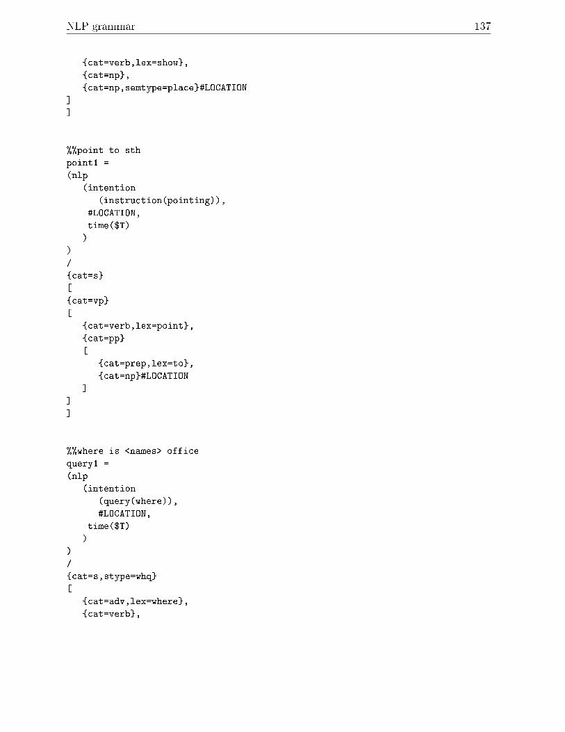
NLP grammar 137
{cat=verb,lex=show},
{cat=np},
{cat=np,semtype=place}#LOCATION
]
].
%%point to sth
point1 =
(nlp
(intention
(instruction(pointing)),
#LOCATION,
time($T)
)
)
/
{cat=s}
[
{cat=vp}
[
{cat=verb,lex=point},
{cat=pp}
[
{cat=prep,lex=to},
{cat=np}#LOCATION
]
]
].
%%where is <names> office
query1 =
(nlp
(intention
(query(where)),
#LOCATION,
time($T)
)
)
/
{cat=s,stype=whq}
[
{cat=adv,lex=where},
{cat=verb},
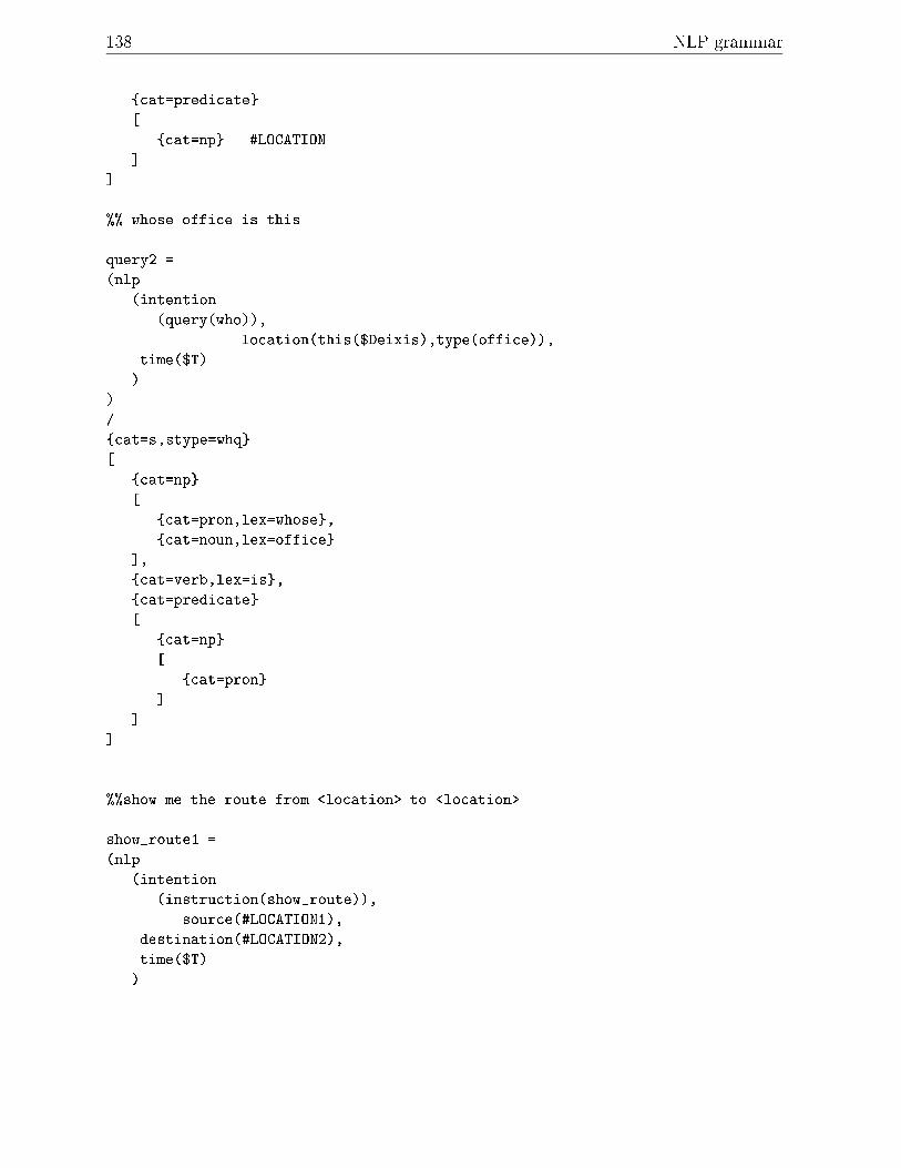
138 NLP grammar
{cat=predicate}
[
{cat=np} #LOCATION
]
].
%% whose office is this
query2 =
(nlp
(intention
(query(who)),
location(this($Deixis),type(office)),
time($T)
)
)
/
{cat=s,stype=whq}
[
{cat=np}
[
{cat=pron,lex=whose},
{cat=noun,lex=office}
],
{cat=verb,lex=is},
{cat=predicate}
[
{cat=np}
[
{cat=pron}
]
]
].
%%show me the route from <location> to <location>
show_route1 =
(nlp
(intention
(instruction(show_route)),
source(#LOCATION1),
destination(#LOCATION2),
time($T)
)

NLP grammar 139
)
/
{cat=s}
[
{cat=vp}
[
{cat=verb,lex=show},
{cat=np},
{cat=np}
[
{cat=det},
{cat=noun},
{cat=pp}
[
{cat=prep},
{cat=np} #LOCATION1
],
{cat=pp}
[
{cat=prep},
{cat=np} #LOCATION2
]
]
]
].
names_office1 =
(location
(person($I),type(office))
)
/
{cat=np}
[
{cat=np,semtype=person,id=$I},
{cat=np}
].
place1 =
(location
(place($I))
)
/
{cat=np,semtype=place,id=$I}
.

Appendix G
The People
Tom Br�ndsted
Tom Br�ndsted, www.cpk.auc.dk/~tb, has an M.Sc. in Germanic Philology & GeneralLinguistics from Odense University, Denmark, 1984. In 1984 he was Instructor in phonet-ics, Dept. of Germanic Philology, in epistemology, Dept. of General Linguistics, OdenseUniversity, in 1985 Lecturer at Dept. of Germanic Philology, University of Basel, Switzer-land, and Dept. of Germanic Philology, University of Zurich, Switzerland, and in 1991research computational linguist, Center for PersonKommunikation, Aalborg University,Denmark. He has been involved with organising a number of international meetings in-cluding ASDS-87 in Freiburg, Germany, IASS-89 in Zurich, Switzerland and DALF-96 atAalborg, Denmark. He has been president of the Danish Society for Computational Lin-guistics since 1995. His research interests include Automatic Speech Understanding (ASR)and Natural Language Processing (NLP): Phonemics and speech recognition, prosody (in-tonation, speech rate), language modelling, syntactic and semantic parsing, generation.His current projects include IntelliMedia 2000+ (http://www.kom.auc.dk/CPK/MMUI),and Reward (http://www.kom.auc.dk/CPK/Speech/Reward).
Paul Dalsgaard
Paul Dalsgaard obtained his degree in Electronic Engineering in 1962 from the TechnicalUniversity of Denmark. He was employed at the Academy of Electronic Engineering inCopenhagen and Aalborg until 1974, where he joined the then founded Aalborg University.He is a Professor in speech communications at the Center for PersonKommunikation, wherehis group is involved in Spoken Dialogue Systems, Speech Recognition and Understanding,Speech Analysis and Synthesis and Design of MultiMedia/MultiModal Human-ComputerInterfaces. The speech communications group has been involved in a large number ofEU-founded projects over the last ten years, which has led to the establishment of demon-strators applying results from ongoing research. Paul Dalsgaard's special interests lie inthe area of applying acoustic-phonetic interdisciplinary research in speech processing and

The People 141
in modelling similar acoustic sounds across languages in an attempt to generalise speechprocessing multilingually. He is a Senior Member of IEEE, is a board member of theEuropean Speech Communication Association (ESCA) and has had a visiting universityposition in Canada.
Lars Bo Larsen
Lars Bo Larsen was born in 1959 near Viborg in the Jutland peninsula of Denmark. Heattended Aalborg University where he obtained his Master's degree in Electronic Engineer-ing in 1984, specialising in Control Engineering. From 1984 to 1986 he served at Aalborguniversity as an Assistant Professor, teaching control engineering and joined a researchproject concerning real-time expert systems for operator communication in powerplants.In 1987 he joined the Center for PersonKommunikation where he worked in the area ofexpert systems for speech recognition. He later focussed on Spoken Dialogue Systemsand more recently also on MultiModal Human Computer Interaction (HCI). He is cur-rently holding a position as Associate Research Professor and is coordinator of the CPKsSpoken Dialogue group and the Master's education in Intelligent MultiMedia at AalborgUniversity.
Michael Manthey
Michael Manthey, an Associate Professor of computer science, received a B.S. in Mathe-matics from Renesselaer Polytechnic Institute, USA and M.Sc. and Ph.D. in ComputerScience from the State University of New York at Bu�alo, USA. Prior to his current po-sition in Aalborg, he taught at Aarhus University, Denmark and the University of NewMexico, Albuquerque, New Mexico, USA. Dr. Manthey's central interest is distributed sys-tems, in particular the description and modelling of self-organizing and distributed naturaland arti�cial systems.
Paul Mc Kevitt
Paul Mc Kevitt is 34 and from D�un Na nGall (Donegal), Ireland on the Northwest of theEU. He is a Visiting Professor of Intelligent MultiMedia Computing at Aalborg Univer-sity, Denmark and a British EPSRC (Engineering and Physical Sciences Research Council)Advanced Fellow in the Department of Computer Science at the University of She�eld,She�eld, England. The Fellowship, commenced in 1994, and releases him from his Asso-ciate Professorship (tenured Lecturership) for 5 years to conduct full-time research on theintegration of natural language, speech and vision processing. He is currently pursuinga Master's degree in Education at the University of She�eld. He completed his Ph.D.in Computer Science at the University of Exeter, England in 1991. His Master's degreein Computer Science was obtained from New Mexico State University, New Mexico, US

142 The People
in 1988 and his Bachelor's degree in Computer Science from University College Dublin(UCD), Dublin, Ireland in 1985. His primary research interests are in Natural LanguageProcessing (NLP) including the processing of pragmatics, beliefs and intentions in dia-logue. He is also interested in Philosophy, MultiMedia and the general area of Arti�cialIntelligence.
Thomas Baltzer Moeslund
Thomas Baltzer Moeslund is 27 and from Randers, Denmark. He is currently a Ph.D. can-didate at the Laboratory of Image Analysis (LIA), Aalborg University, Denmark withinthe area of computer vision and virtual reality interfaces. He has worked as a ResearchAssistant at the Center for PersonKommunikation (CPK), Aalborg University, Denmarkon Intelligent MultiMedia and computer vision. He obtained his Master's degree in Electri-cal Engineering with a specialization in computer vision from Aalborg University in 1996.During his study he visited computer vision laboratories at the University of Reading, Eng-land, University of Tennessee, Knoxville, US and University of California, San Diego, US.His primary research interests are computer vision, intelligent interfaces and MultiModalsystems.
Kristian G. Olesen
Kristian G. Olesen is 40 and from the northern Jutland at the top of Denmark. He isAssociate Professor at the Department for Medical Informatics and Image Analysis atAalborg University. He holds a Bachelor's degree in Mathematics and a Master's degree inComputer Science, both obtained at Aalborg University, where he also received his Ph.D.degree in 1992. His research interest is centered around decision support systems, includingboth methodological issues and development of applications, primarily within the medicaldomain. The focus of his research is on operationalisation of theories and methods, andhe is cofounder and vicechairman of the company HUGIN Expert Ltd. which marketssoftware for Bayesian Networks.

References
Aho, Alfred V., John E. Hopcroft and Je�rey D. Ullman (1983) Data structures and
algorithms. Reading, MA: Addison-Wesley.
Andr�e, Elisabeth, G. Herzog, and T. Rist (1988) On the simultaneous interpretationof real-world image sequences and their natural language description: the systemSOCCER. In Proceedings of the 8th European Conference on Arti�cial Intelligence,449-454, Munich, Germany.
Andr�e, Elisabeth and Thomas Rist (1993) The design of illustrated documents as a plan-ning task. In Intelligent multimedia interfaces, M. Maybury (Ed.), 75-93. Menlo Park,CA: AAAI Press.
B�kgaard, Anders (1996) Dialogue management in a generic dialogue system. In Pro-
ceedings of the Eleventh Twente Workshop on Language Technology (TWLT), Dialogue
Management in Natural Language Systems, 123-132, Twente, The Netherlands.
B�kgaard, Anders, T. Br�ndsted, A. Roman, and P. Wetzel (1992) Advanced dialogue
design. SUNSTAR Deliverable IV.6-1. Esprit Project 1094, Center for PersonKom-munikation, Aalborg University, Denmark.
B�kgaard, Anders, O. Bernsen, T. Br�ndsted, P. Dalsgaard, H. Dybkj�r, L. Dybkj�r, J.Kristensen, L.B. Larsen, B. Lindberg, B. Maegaard, B. Music, L. O�ersgaard, and C.Povlsen (1995) The Danish spoken language dialogue project - a general overview. InProceedings of ESCA WS on Spoken Dialogue Systems: theory and applications, Vigs�,
Denmark, Paul Dalsgaard, Lars Bo Larsen, Louis Bovis, and Ib Thomsen (Eds.), 89-92.Center for PersonKommunikation, Aalborg University, Denmark.
Bai, Bo Nygaard, Tom Br�ndsted, and Paul Dalsgaard (1998) Technical speci�cation:
service creation tool. Technical Report, Reward WP3, Deliveable LE-2632-D3.2 (incon�dence), Center for PersonKommunikation, Aalborg University, Denmark, March.
Bakman, Lau, Mads Blidegn, Thomas Dorf Nielsen, and Susana Carrasco Gonzalez(1997a) NIVICO - Natural Interface for VIdeo COnferencing. Project Report (8thSemester), Department of Communication Technology, Institute 8, Aalborg Univer-sity, Denmark.
Bakman, Lau, Mads Blidegn, and Martin Wittrup (1997b) Improving human computer
interaction by adding speech, gaze, tracking and agents to a WIMP based environment.Project Report (9th/10th Semester), Department of Communication Technology, In-stitute 8, Aalborg University, Denmark.
Bech, A. (1991) Description of the EUROTRA framework. In The Eurotra Formal

144
Speci�cations, Studies in Machine Translation and Natural Language Processing, C.Copeland, J. Durand, S. Krauwer, and B. Maegaard (Eds), Vol. 2, 7-40. Luxembourg:O�ce for O�cial Publications of the Commission of the European Community.
Bresnan, J. (Ed.) (1982) The mental representation of grammatical relations. Cambridge,Mass.: MIT Press.
Bruegge, Bernd and Ben Bennington (1996) Applications of wireless research to realindustrial problems: applications of mobile computing and communication. In IEEE
Personal Communications, 64-71, February.
Br�ndsted, T. (1998) nlparser. WWW: http://www.kom.auc.dk/~tb/nlparser.
Br�ndsted, T., and L.B. Larsen (1994) Representation of acoustic and linguistic knowl-
edge in continuous speech recognition. Spoken Language Dialogue Systems, TechnicalReport 5, Center for PersonKommunikation, Aalborg University, Denmark.
Carenini, G., F. Pianesi, M. Ponzi and O. Stock (1992) Natural language generation
and hypertext access. IRST Technical Report 9201-06, Instituto Per La Scienti�ca ETecnologica, Loc. Pant e Di Povo, I-138100 Trento, Italy.
Chomsky, N. (1956) Three models for the description of language. In I.R.E. Transactions
on Information Theory, Vol. IT-2, 113-124, September.
Chomsky, N. (1957) Syntactic structures. The Hague, The Netherlands: Mouton.
Christensen, Heidi, B�rge Lindberg and Pall Steingrimsson (1998a) Functional speci�ca-tion of the CPK Spoken LANGuage recognition research system (SLANG). TechnicalReport, Center for PersonKommunikation, Aalborg University, Denmark, March.
Christensen, Heidi, B�rge Lindberg and Pall Steingrimsson (1998b) Technical speci�ca-tion of the CPK Spoken LANGuage recognition research system (SLANG). TechnicalReport, Center for PersonKommunikation, Aalborg University, Denmark, March.
CPK Annual Report (1998) CPK Annual Report. Center for PersonKommunikation(CPK), Fredrik Bajers Vej 7-A2, Institute of Electronic Systems (IES), Aalborg Uni-versity, DK-9220, Aalborg, Denmark.
Dalsgaard, Paul and A. Baekgaard (1994) Spoken Language Dialogue Systems. In Prospectsand Perspectives in Speech Technology: Proceedings in Arti�cial Intelligence, Chr.Freksa (Ed.), 178-191, September. M�unchen, Germany: In�x.
Denis, M. and M. Carfantan (Eds.) (1993) Images et langages: multimodalit�e et mod-
elisation cognitive. Actes du Colloque Interdisciplinaire du Comit�e National de laRecherche Scienti�que, Salle des Conf�erences, Si�ege du CNRS, Paris, April.
Dennett, Daniel (1991) Consciousness explained. Harmondsworth: Penguin.
Earley, Jay (1970) An e�cient context-free parsing algorithm. In Communications of the
ACM, Vol 13, 2, February.
Engberg, Inger Sams�, Anya Varnich Hansen, Ove Andersen, and Paul Dalsgaard (1997)Design, recording and veri�cation of a Danish emotional speech database. In Pro-
ceedings of the 5th European Conference on Speech Communication and Technology
(Eurospeech '97), Vol. 4, 1695-1698, Rhodos, Greece, September.
Fink, G.A., N. Jungclaus, H. Ritter, and G. Sagerer (1995) A communication frameworkfor heterogeneous distributed pattern analysis. In Proc. International Conference on

References 145
Algorithms and Applications for Parallel Processing, V. L. Narasimhan (Ed.), 881-890.IEEE, Brisbane, Australia.
Fink, Gernot A., Nils Jungclaus, Franz Kummert, Helge Ritter and Gerhard Sagerer(1996) A distributed system for integrated speech and image understanding. In Pro-
ceedings of the International Symposium on Arti�cial Intelligence, Rogelio Soto (Ed.),117-126. Cancun, Mexico.
Fraser N. and P. Dalsgaard (1996) Spoken dialogue systems: a European perspective.In Proceedings of the International Symposium on Spoken Dialogue (ISSD 96), Octo-
ber, Wyndham Franklin Plaza Hotel, Philadelphia, US, Fujisaki, Hiroya (Ed.), 25-36.Tokyo, Japan: Acoustical Society of Japan (ASJ).
Garofolo, J.S. (1988) The structure and format of the Darpa TIMIT CD-ROM prototype.Darpa Timit CD-ROM, an ccoustic phonetic continuous speech database, TT, MIT,US NIST, SRI December 1988, pp. 1-9. (distributed on the DARPA TIMIT CD-ROM).
Garofolo, John S., Lori F. Larnel, William F. Fisher, Jonathon G. Fiscus, David S. Pallett,and Nancy L. Dahlgren (1993) DARPA TIMIT acoustic-phonetic continuous speech
corpus. US NIST Internal Report 4930. NTIS, U.S. Department of Commerce, PortRoyal Road, Spring�eld, VA.
Gazdar, G., E. Klein, G.K. Pullum, and I.A. Sag (1985) Generalized phrase structure
grammar. Oxford, England: Blackwell Publishing and Cambridge, Massachusetts,US: Harvard University Press.
Gonzalez, R.C. and R.E. Woods (1993) Digital image processing. Reading, Massachusetts:Addison Wesley.
Herzog, G. and G. Retz-Schmidt (1990) Das System SOCCER: Simultane Interpreta-tion und naturalichsprachliche Beschreibung zeitveranderlicher Szenen. In Sport und
Informatik, J. Perl (Ed.), 95-119. Schorndorf: Hofmann.
Herzog, G., C.-K. Sung, E. Andre, W. Enkelmann, H.-H. Nagel, T. Rist, and W. Wahlster(1989) Incremental natural language description of dynamic imagery. InWissenbasierte
Systeme. 3. Internationaler GI-Kongress, C. Freksa and W. Brauer (Eds.), 153-162.Berlin: Springer-Verlag.
IEEE Spectrum (1996) Technology 1996: analysis and forecast issue Can we talk? the
great hookup debate. January.
IEEE Spectrum (1997) Sharing virtual worlds: avatars, agents, and social computing. Vol.34, No. 3, March.
Infovox (1994) INFOVOX: Text-to-speech converter user's manual (version 3.4). Solna,Sweden: Telia Promotor Infovox AB.
JAI (1996) Cameras for surveillance. Copenhagen, Denmark: JAI A-S.
Jensen, Finn V. (1996) An introduction to Bayesian Networks. London, England: UCLPress.
Jensen, Frank (1996) Bayesian belief network technology and the HUGIN system. InProceedings of UNICOM seminar on Intelligent Data Management, Alex Gammerman(Ed.), 240-248. Chelsea Village, London, England, April.

146
Jensen, Jesper, Claus Nielsen, Ove Andersen, Egon Hansen, and Niels-J�rn Dyhr (1998)A speech synthesizer with modelling of the Danish \st�d". In Proceedings of the IEEE
Nordic Signal Processing Symposium (Norsig '98), 8-11, June.
Kay, M. (1985) Parsing in functional uni�cation grammar. In Natural Language Parsing,D.R. Dowty, Lauri Karttunen and Arnold M. Zwicky (Eds.), 251-278. CambridgeUniversity Press: Cambridge, Engand.
Kj�rsdam, Finn and Stig Enemark (1994) The Aalborg experiment - project innovation
in university education. Aalborg, Denmark: Aalborg Universitetsforlag (Aalborg Uni-versity Press).
Kosslyn, S.M. and J.R. Pomerantz (1977) Imagery, propositions and the form of internalrepresentations. In Cognitive Psychology, 9, 52-76.
Larsen, L.B. (1996) Voice controlled home banking - objectives and experiences of theEsprit OVID project. In Proceedings of IEEE Third Workshop on Interactive Voice
Technology for Telecommunications Applications (IVTTA-96), 45-48, New Jersey, US,September (IEEE 96-TH-8178).
Lausen, Henrik (1997) LaserXI(2.2) documentation. Laser Interface, Center For AdvancedTechnology (CAT), Roskilde, Denmark.
Lee, K. (1988) Large-vocabulary speaker-independent continuous speech recognition: The
SPHINX System. Technical Report, CMU-CS-88-148, Carnegie Mellon University,Pittsburgh, PA, April.
Leth-Espensen, Poul and B�rge Lindberg (1995) Application of microphone arrays for
remote voice pickup - a feasibility study - �nal report. RVP (Remote Voice Pickup)
- Report 2 (Commercial in con�dence). Center for PersonKommunikation, AalborgUniversity, Denmark.
Leth-Espensen, Poul and B�rge Lindberg (1996) Separation of speech signals using eigen-�ltering in a dual beamforming system. In Proc. IEEE Nordic Signal Processing
Symposium (NORSIG), Espoo, Finland, September, 235-238.
Lindberg, B., and J. Kristiansen (1995) Real-time continuous speech recognition within
dialogue systems. Spoken Language Dialogue Systems, Report 8, Center for Person-Kommunikation, Aalborg University, Denmark.
Maa�, Wolfgang, Peter Wizinski, Gerd Herzog (1993) VITRA GUIDE: Multimodal route
descriptions for computer assisted vehicle navigation. Bereich Nr. 93, Universitat desSaarlandes, FB 14 Informatik IV, Im Stadtwald 15, D-6600, Saarbrucken 11, Germany,February.
Maegaard, B., H.D. Maas (1985) De�nition of the Eurotra user language. Final Report(ETS-7-DK/D), submitted to the Commission of the European Communities (CEC).
Manthey, Michael J. (1991) US Patents 4,829,450, 5,367,449, and others pending. Theintent is to license freely (on request) to individuals and research or educational insti-tutions for non-pro�t use..
Manthey, Michael J. (1994) Toward an information mechanics. In Proceedings of the
Third IEEE Workshop on Physics and Computation, D. Matzke, (Ed.), 95-109. Dallas,Texas, November.

References 147
Manthey, Michael J. (1997a) Distributed computation, the twisted isomorphism, and auto-
poiesis. Technical Report R-97-5007, Department of Computer Science, Aalborg uni-versity, Denmark, June.
Manthey, Michael J. (1997b) The phase web paradigm and anticipatory systems, two short
papers. Technical Report R-97-5006, Department of Computer Science, Aalborg uni-versity, Denmark, June.
Manthey, Michael J. (1998a) Distributed Computation, the Twisted Isomorphism, andAuto-Poiesis. In Proceedings of the First International Conference on Computing An-
ticipatory Systems (CASYS 97), D. Dubois, (Ed.). Liege, Belgium, August.
Manthey, Michael J. (1998b) The Phase Web Paradigm. In International Journal of
General Systems, special issue on General Physical Systems Theories, K. Bowden(Ed.). in press.
Manthey, Michael J. (1998c) topsy. WWW: http://www.cs.auc.dk/topsy/.
Maybury, Mark (1991) Planning multimedia explanations using communicative acts. InProceedings of the Ninth American National Conference on Arti�cial Intelligence (AAAI-
91), Anaheim, CA, July 14-19.
Maybury, Mark (Ed.) (1993) Intelligent multimedia interfaces. Menlo Park, CA: AAAIPress.
Maybury, Mark (Ed.) (1997) Intelligent multimedia information retrieval. Menlo Park,CA: AAAI/MIT Press, http://www.aaai.org:80/Press/Books/Maybury-2/.
Maybury, Mark and Wolfgang Wahlster (Eds.) (1998) Readings in intelligent user inter-
faces. Los Altos, CA: Morgan Kaufmann Publishers.
Mc Kevitt, Paul (1994) Visions for language. In Proceedings of the Workshop on Integra-
tion of Natural Language and Vision processing,, Twelfth American National Confer-ence on Arti�cial Intelligence (AAAI-94), Seattle, Washington, USA, August, 47-57.
Mc Kevitt, Paul (Ed.) (1995/1996) Integration of Natural Language and Vision Processing
(Vols. I-IV). Dordrecht, The Netherlands: Kluwer-Academic Publishers.
Mc Kevitt, Paul (1997) SuperinformationhighwayS. In \Sprog og Multimedier" (Speech
and Multimedia), Tom Br�ndsted and Inger Lytje (Eds.), 166-183, April 1997. Aal-borg, Denmark: Aalborg Universitetsforlag (Aalborg University Press).
Minsky, Marvin (1975) A framework for representing knowledge. In The Psychology of
Computer Vision, P.H. Winston (Ed.), 211-217. New York: McGraw-Hill.
Moeslund, Thomas B., Lau Bakman, and Mads Blidegn (1998) Controlling a move-
able laser from a PC. Technical Report R-98-1002, Center for Personkommunikation(CPK), Institute of Electronic Systems (IES), Aalborg University, Denmark.
Music, B., L. O�ersgaard, D. Christensen (1994) The NLP module. Spoken LanguageDialogue Systems, Report 7, Center for PersonKommunikation, Aalborg University,Denmark.
mySQL (1998) WWW: http://www.tcx.se/. Stockholm, Sweden: T.c.X DataKonsult AB.
Neumann, B. and H.-J. Novak (1986) NAOS: Ein System zur naturalichsprachlichenBeschreibung zeitveranderlicher Szenen. In Informatik. Forschung und Entwicklung,1(1): 83-92.

148
Nielsen, Claus, Jesper Jensen, Ove Andersen, and Egon Hansen (1997) Speech synthesis
based on diphone concatenation. Technical Report, No. CPK971120-JJe (in con�-dence), Center for PersonKommunikation, Aalborg University, Denmark.
Nielsen, J�rgen (1997) Distributed applications communication system applied on Intelli-
Media WorkBench. Project Report (8th Semester), Department of Medical Informat-ics and Image Analysis (MIBA), Institute 8, Aalborg University, Denmark.
Odell, Julian, Dave Ollason, Valtcho Valtchev, and David Whitehose (1997) The HAPI
Book (version 1.0): a description of the HTK application programming interface. Cam-bridge, England: Entropic Cambridge Research Laboratory Ltd..
Okada, Naoyuki (1996) Integrating vision, motion and language through mind. In Inte-
gration of Natural Language and Vision Processing, Volume IV, Recent Advances, McKevitt, Paul (ed.), 55-80. Dordrecht, The Netherlands: Kluwer Academic Publishers.
Okada, Naoyuki (1997) Integrating vision, motion and language through mind. In Pro-
ceedings of the Eighth Ireland Conference on Arti�cial Intelligence (AI-97), Volume 1,7-16. University of Uster, Magee, Derry, Northern Ireland, September.
Partridge, Derek (1991) A new guide to Arti�cial Intelligence. Norwood, New Jersey:Ablex Publishing Corporation.
Pentland, Alex (Ed.) (1993) Looking at people: recognition and interpretation of human
action. IJCAI-93 Workshop (W28) at The 13th International Conference on Arti�cialIntelligence (IJCAI-93), Chamb�ery, France, EU, August.
Pollard, C. (1984) Generalized phrase structure grammars, head grammars, and natural
languages. Ph.D. thesis, Department of Linguistics, Stanford University, CA, US.
Pollard, C., and I.A. Sag (1994) Head-driven phrase structure grammar. Chicago, IL, US:Univeristy of Chicago Press.
Povlsen, C. (1994) Sublanguage de�nition and speci�cation. Spoken Language DialogueSystems, Report 4, Center for PersonKommunikation, Aalborg University, Denmark.
Power, Kevin, Caroline Matheson, Dave Ollason and Rachel Morton (1997) The grapHvitebook (version 1.0). Cambridge, England: Entropic Cambridge Research LaboratoryLtd..
Press, W.H., B.P. Flannery, S.A. Teukolsky and W.T. Vetterling (1990) Numerical recipes
in C - the art of scienti�c computing. Cambridge, England: Cambridge UniversityPress.
Pylyshyn, Zenon (1973) What the mind's eye tells the mind's brain: a critique of mentalimagery. In Psychological Bulletin, 80, 1-24.
Retz-Schmidt, Gudala (1991) Recognizing intentions, interactions, and causes of planfailures. In User Modelling and User-Adapted Interaction, 1: 173-202.
Retz-Schmidt, Gudala and Markus Tetzla� (1991)Methods for the intentional description
of image sequences. Bereich Nr. 80, Universitat des Saarlandes, FB 14 Informatik IV,Im Stadtwald 15, D-6600, Saarbrucken 11, Germany, EU, August.
Rich, Elaine and Kevin Knight (1991) Arti�cial Intelligence. New York: McGraw-Hill.
Rickheit, Gert and Ipke Wachsmuth (1996) Collaborative Research Centre \Situated Ar-ti�cial Communicators" at the University of Bielefeld, Germany. In Integration of

References 149
Natural Language and Vision Processing, Volume IV, Recent Advances, Mc Kevitt,Paul (ed.), 11-16. Dordrecht, The Netherlands: Kluwer Academic Publishers.
Roehle, B. (1997) Channeling the data ow. In IEEE Spectrum, March, 32-38.
Ross, S.M. (1987) Introduction to probability and statistics for engineers and scientists.Chichester, England: John Wiley and Sons.
Rudnicky, Alexander I., Stephen D. Reed, Eric H. Thayer (1996) SpeechWear: a mobilespeech system. In Proceedings of International Symposium on Spoken Dialogue (ISSD
96), October 2-3, Wyndham Franklin Plaza Hotel, Philadelphia, USA, Fujisaki, Hiroya(Ed.), 161-164. Tokyo, Japan: Acoustical Society of Japan (ASJ).
Shieber, S.M. (1984) The design of a computer language for linguistic information. In Pro-ceedings of the 10th International Conference on Computational Linguistics (Coling-
84), Stanford, CA, 362-366.
Shieber, S.M. (1985) Using restriction to extend parsing algorithms for complex-feature-based formalims. In Proceedings of the 22nd Annual Meeting of the Association for
Computational Linguistics, Chicago, Il, 145-152.
Shieber, S.M. (1986) An introduction to uni�cation based approaches to grammar. CSLILecture Notes Series, Number 4. Stanford, CA: Center for Study of Language andInformation
Smailagic, Asim and P. Siewiorek (1996) Matching interface design with user tasks: modal-ities of interaction with CMU wearable computers. In IEEE Personal Communica-
tions, 14-25, February.
Stock, Oliviero (1991) Natural language and exploration of an information space: the AL-Fresco Interactive system. In Proceedings of the 12th International Joint Conference
on Arti�cial Intelligence (IJCAI-91), 972-978, Darling Harbour, Sydney, Australia,August.
Th�orinsson, Kris R. (1996) Communicative humanoids: a computational model of psy-
chosocial dialogue skills. Ph.D. thesis, Massachusetts Institute of Technology.
Th�orinsson, Kris R. (1997) Layered action control in communicative humanoids. In Pro-
ceedings of Computer Graphics Europe '97, June 5-7, Geneva, Switzerland.
Tsai, R.Y. (1987) A versatile camera calibration for high-accuracy 3D machine visionmetrology using o�-the self TV cameras and lenses. In IEEE Journal of Robotics and
Automation, Vol. 3, No. 4, August.
Tuns, Nicolae G. and Thomas Dorf Nielsen (1998) Experimenting with phase web as AI
support in the CHAMELEON system. Project Report (9th semester), Department ofComputer Science, Institute 8, Aalborg University, Denmark.
Uhlin, Tomas and Johansson, Kenneth (1996) Autonomous mobile systems: a study of
current research. The Royal Institute of Technology (KTH), Stockholm, Sweden.
von Hahn, Walther (1997) Personal communication. .
Wahlster, Wolfgang (1988) One word says more than a thousand pictures: On the auto-
matic verbalization of the results of image sequence analysis. Bereich Nr. 25, Univer-sitat des Saarlandes, FB 14 Informatik IV, Im Stadtwald 15, D-6600, Saarbrucken 11,Germany, February.

150
Wahlster, Wolfgang, Elisabeth Andr�e, Wolfgang Finkler, Hans-Jurgen Pro�tlich, andThomas Rist (1993) Plan-based integration of natural language and graphics gen-eration. In Arti�cial Intelligence, Special issue on natural language generation, 63,387-427.
Waibel, Alex, Minh Tue Vo, Paul Duchnowski and Stefan Manke (1996) Multimodalinterfaces. In Integration of Natural Language and Vision Processing, Volume IV, Re-
cent Advances, Mc Kevitt, Paul (Ed.), 145-165. Dordrecht, The Netherlands: KluwerAcademic Publishers.
Waltz, David (1975) Understanding line drawings of scenes with shadows. In The psy-
chology of computer vision, Winston, P.H. (Ed.), 19-91. New York: McGraw-Hill.Winograd, T. (1983) Language as a cognitive process - Volume I: Syntax. Reading, Mas-
sachusetts: Addison-Wesley.Young Steve J., N.H. Russell, and J.H.S. Thornton (1989) Token passing: a simple con-
ceptual model for connected speech recognition systems. Technical Report, CambridgeUniversity Engineering Department, Cambridge, England.
Young, Steve J., Joop Jansen, Julian Odell, Dave Ollason, and Phil Woodland (1996)The HTK book (version 2.0). Cambridge, England: Entropic Cambridge ResearchLaboratory Ltd..