Embed Size (px)
Citation preview

1
KOM
COURSE FILE

2
GEETHANJALI COLLEGE OF ENGINEERING AND
TECHNOLOGY
DEPARTMENT OF Mechanical Engineering
(Name of the Subject / Lab Course) : kinematics of Machinery
(JNTU CODE )54014 Programme : UG
Branch: MECH Version No : 01
Year: II Updated on : 05/12/2015
Semester: II No. of pages :
Classification status (Unrestricted / Restricted )
Distribution List :
Prepared by : 1) Name : k Raju
2) Sign :
3) Design : Assistant professor
4) Date : 07/12/2015
Verified by : 1) Name :
2) Sign :
3) Design :
4) Date :
* For Q.C Only.1) Name :
2) Sign :
3) Design :
4) Date :
Approved by : (HOD ) 1) Name :T.Siva Prasad
2) Sign : 3) Date :

3
Contents S.No. Item Page No.
1. Cover page 2
2. Syllabus copy 4
3. Vision of the Department 5
4. Mission of the Department 5
5. PEOs and POs 6
6. Course objectives and outcomes 7
7. Brief importance of the course and how it fits into the curriculum 8
8. Prerequisites if any 8
9. Instructional Learning Outcomes 8
10. Course mapping with PEOs and POs 13
11. Class Time table 15
12. Individual Time table 15
13. Lecture schedule with methodology being used / adopted 17
14. Detailed notes 21
15. Additional topics 34
16. University previous Question papers of previous years 37
17. Question Bank 39
18. Assignment Questions 42
19. Unit-wise quiz questions 46
20. Tutorial Problems 53

4
2. Syllabus copy JAWAHARLAL NEHRU TECHNOLOGIVAL UNIVERSITY HYDERABAD
III Year B.Tech. MECH -I Sem L T/ P/ D C 4 -/ - / - 4
KINEMATICS OF MACHINERY
UNIT–I
Mechanisms :Definition of link, element, pair, kinematic chain, mechanism and machine,
Grubler’s criterion, single and double slider chains, inversions of quadratic cycle chain,
inversions of single and double slider crank chains. mechanism with lower pairs and straight
line motion mechanism- Pantograph, Peaucerlier and Hart, Tchebicheff’s mechanism.
UNIT–II:
Straight line motion mechanisms: Graphical methods to find velocities of mechanisms,
instantaneous centre, body centre and space centre, Kennedy’s theorem, graphical
determination of acceleration of different mechanisms including Coriolis component of
acceleration, analytical method to find the velocity and acceleration, analysis of four bar
mechanism with turning pairs.
UNIT–III
KINEMATICS: Velocity and acceleration – Motion of link in machine – Determination of Velocity and acceleration diagrams – Graphical method – Application of relative velocity method four bar chain.
Analysis of Mechanisms: Analysis of slider crank chain for displacement, velocity and acceleration of slider – Acceleration diagram for a given mechanism, Klein’s construction, Coriolis acceleration, determination of Coriolis component of acceleration.
Plane motion of body: Instantaneous center of rotation, centroids and axodes – relative
motion between two bodies – Three centers in line theorem – Graphical determination of
instantaneous centre, diagrams for simple mechanisms and determination of angular velocity
of points and links
UNIT–IV
Cams: Types of cams and followers, displacement diagrams for followers, uniform motion,
parabolic motion, simple harmonic motion, cycloidal motion, drawing cam profile with

5
knife–edge follower, translating roller follower and translating flat follower, cams of
specified contour, tangent cam with roller follower, circular arc (convex) cam with roller
follower.
UNIT–V
Gears: Classification of gears, spur gears, nomenclature, law of gear tooth action, involute
as gear tooth profile, interference of involute gears, minimum number of teeth to avoid
interference, contact ratio, cycloidal tooth profile, comparision of involute and cycliodal
tooth profile.
Helical Gears: Helical gear tooth relations, contact of helical gear teeth, gear trains–simple
and compound, reverted and epicyclic gear trains.
Text Books:
4. Thomas Bevan, Theory of Machines, CBS Publishers, 2009.
5. S.S. Rattan, Theory of Machines, Tata McGraw Hill Publishers, 3rd Edition, 2009.
Suggested Reading:
1. J.E.Shigley, Theory of Machines, Tata Mc.Graw Hill Publishers, New Delhi, 3rd Edition,
2005.
2. C.S. Sharma and Kamlesh Purohit, Theory of Mechanisms and Machines, PHI Learning
Pvt. Limited, 2006
3. Amitabh Ghosh and A.K.Mallik, Theory of Machines, East West Publications, 3rd
Edition, 2009.
3. Vision of the Department To become a Regionally and Nationally recognized Department in providing high Quality
Education in Mechanical Engineering, leading to well qualified, innovative and successful engineers.
4. Mission of the Department To prepare professionally competent Mechanical Engineers by developing analytical and
research abilities.

6
Prepare its graduates to pursue life-long learning, serve the profession and meet intellectual, ethical and career challenges.
To develop linkages with R&D organizations and Educational Institutions in India and abroad for excellence in teaching, research and consultancy practices.
5. PEOs and POs The Program Educational Objectives of Mechanical Engineering Program are developed to provide guidance to Graduating Mechanical Engineers, so that they can contribute effectively to the advancement of needs of Mechanical Engineering Profession.
The graduates from Mechanical Engineering program are expected to demonstrate within three to five years of graduation that
1. They practice Mechanical Engineering in all areas of Design, Thermal and Manufacturing Engineering in all types of industrial sectors.
2. They apply technical knowledge and skills to real life technical challenges in various fields of Mechanical Engineering.
3. They are competent in advanced Research and Development and creative efforts in Mechanical Engineering and allied areas of Science and Technology.
4. They practice Mechanical Engineering in a professional, responsible and ethical manner for the benefit of the industry and society
The Program Outcomes of the Department of Mechanical Engineering are to educate graduates, who by the time of graduation will be able to demonstrate:
An ability to apply knowledge of mathematics, science, and engineering. An ability to design and conduct experiments, as well as to analyze and interpret
data. An ability to design a system, component, or process to meet desired needs. An ability to function on multi-disciplinary teams. An ability to identify, formulates, and solves engineering problems. An understanding of professional and ethical responsibility. An ability to communicate effectively. An ability to apply their broad education toward the understanding of the impact of
engineering solutions in a global and societal context. Recognition of the need for, and the ability to engage in life-long learning. Knowledge of contemporary issues. An ability to use the techniques, skills, and modern engineering tools necessary for
engineering practice.

7
6. Course Objectives and Outcomes Course Objectives: Student will acquire acknowledge in
1. Analysis of mechanisms,
2. Drawing displacement diagrams for followers with various types of motions,
3. Cam profile drawing for various followers,
4. Estimation of transmission of power by belts and application of various gears and gear trains.
Course Outcomes:
Student will demonstrate knowledge in
1. Designing a suitable mechanism depending on application
2. Drawing displacement diagrams and cam profile diagram for followers executing different types of motions
and various configurations of followers,
3. Drawing velocity and acceleration diagrams for different mechanisms,
4. Selecting gear and gear train depending on application.
7. Brief Importance of the Course and how it fits into the
curriculum
This course introduces students to involve in kinematics study how a physical system might
develop or alter over time and study the causes of those changes. In addition, Newton
established the fundamental physical laws which govern dynamics in physics. By studying
his system of mechanics, dynamics can be understood. In particular, kinematics is mostly
related to Newton's second law of motion. However, all three laws of motion are taken into
consideration, because these are interrelated in any given observation or experiment.
8. Prerequisites if any
1. Introductory geometric synthesis of linkages
2. Mobility analysis of mechanisms

8
3. Kinematics of machines
4. Design of cam-follower mechanisms
5. Analysis and synthesis of gear trains
6. Calculus and vector algebra
9. Instructional Learning Outcomes
Learning outcomes are the key abilities and knowledge that will be assessed
UNIT-I: Mechanisms First unit deals with the degree of freedom of a mechanism and identify the mobility of a four bar mechanism. Analysis the extremes of the transmission angle in a crank and rocker mechanism. Calculation of the displacements of a planar mechanism Apply Freudenstein’s Equation in the analysis of a four Synthesize a four bar mechanism motion generator for two or three positions of a moving plane Synthesize a four bar mechanism function generator for three precision.
UNIT–II: Straight line motion mechanisms
Unit-II deals with the velocities of planar mechanism and the accelerations of planar mechanism Recognize friction and its effects in mechanical components. Analyze planar mechanism for displacement, velocity and acceleration graphically.
UNIT–III:Kinematics
Unit-III deals with Velocity and acceleration Motion of link in machine Determination of Velocity and acceleration diagrams and Graphical method, Application of relative velocity method four bar chain. Analyses of slider crank chain for displacement, velocity and acceleration.
UNIT–IV:Cams
Unit-IV deals with the Types of cams and followers, displacement diagrams for followers,
uniform motion, parabolic motion, simple harmonic motion, cycloidal motion, drawing cam
profile with knife–edge follower. Analyze various motion transmission elements like gears,
gear trains, cams, belt drive and rope drive.

9
UNIT–V:Gears
Unit-V deals with the Utilize analytical, mathematical and graphical aspects of kinematics of machines for effective design. Perform the kinematic analysis of a given mechanism. Analysis interference of involutes gears, minimum number of teeth to avoid interference, contact ratio, cycloidal tooth profile, comparison of in volute and cycloidal tooth profile.
10. Course mapping with PEOs and POs
Mapping of Course with Programme Educational Objectives: S.No Course
component code course Semester PEO
1 PEO 2
PEO 3
1 Kinematics
of machinery
KOM 2 √ √
Mapping of Course outcomes with Programme outcomes: *When the course outcome weightage is < 40%, it will be given as moderately correlated (1). *When the course outcome weightage is >40%, it will be given as strongly correlated (2).
POs 1 2 3 4 5 6 7 8 9 10 11 12 13
Kin
emat
ics o
f Mac
hine
ry
STLD 2 2 2 1 2 1 1 2 2 2 CO 1:
1. a) Explain the
ability to synthesis,
both graphically
and analytically,
multilink
mechanisms.
b) Designing a
suitable mechanism
depending on
application
2 2 2 1 2 1 1 2 2 2

10
CO 2: practicing of
Mechanical
Engineering in all areas
of Design, Thermal and
Manufacturing
Engineering in all types
of industrial sectors.
2 2 2 1 2 1 1 2 2 2
CO 3: synthesis of
mechanisms on four
chain, the unknown
lengths of links.
2 2 2 1 2 1 1 2 2 2
CO 4:static and
dynamic equilibriums
of links in mechanical
elements. unknown
lengths of links.
2 2 2 1 2 1 1 2 2 2
CO 5
a)Drawing velocity and
acceleration diagrams
for different
mechanisms,
b) Selecting gear and
gear train depending on
application.
1 2 2 2 1 1 1 1 2 2
11
1.8. Unit wise Summary
Sl No
Unit No.
Total No. of
Periods Topics to be covered
Reg./ Additional
Teaching aids used LCD. OHP.BB
Remarks
1 I 7 MECHANISMS: Elements or Links – Classification––Rigid Link, flexible and fluid link
Regular OHP,BB
2 Types of kinematic pairs sliding, turning, rolling, screw and spherical pairs – lower and higher pairs
Regular OHP,BB
3 Closed and open pairs – constrained motion – completely,
Regular OHP,BB
4 Partially or successfully constrained and incompletely constrained
Regular OHP,BB
5 MACHINES : Mechanism and machines – classification of machines – kinematic chain
Regular BB
6 Inversion of mechanism – inversion of mechanism – inversions of quadric cycle,
Regular BB
7 Chain – single and double slider crank chains. Regular Tutorial class-1 8 II 6 STRAIGHT LINE MOTION MECHANISMS:–– Regular OHP,BB 9 Exact and approximate copiers and generated types Regular BB 10 Peaucellier, Hart and Scott Russul Regular OHP,BB 11 Grasshopper – Watt T. Chebicheff and Robert Regular BB 12 Mechanisms and straight line motion, Regular BB 13 Pantograph. Regular OHP,BB Tutorial Class-2 Solving University papers Assignment test-1 BB 14 III 10 KINEMATICS: Velocity and acceleration –
Motion of link in machine Regular BB
15 Determination of Velocity and acceleration diagrams – Graphical method
Regular
16 Application of relative velocity method four bar chain. Analysis of Mechanisms: Analysis of slider crank chain for displacement,
Regular OHP,BB
17 Velocity and acceleration of slider – Acceleration diagram for a given mechanism,
Regular OHP,BB
18 Kleins construction, Coriolis acceleration, Regular BB 19 Determination of Coriolis component of
acceleration. Regular BB
20 Plane motion of body: Instantaneous center of rotation, Centroids and axodes
Regular OHP,BB
21 Relative motion between two bodies – Three centres in line theorem
Regular BB
22 Graphical determination of instantaneous centre, diagrams for simple mechanisms and
Regular
23 Determination of angular velocity of points and Regular

12
links. Tutorial class-3 Regular 24 IV 6 STEERING Mechanisms: Conditions for correct
steering Regular OHP,BB
25 Davis Steering gear, Regular BB 26 Ackerman’s steering –gear velocity ratio. Regular LCD,OHP,BB 27 HOOKE’S JOINT: Single and double Hooke’s
joint. Regular OHP,BB
28 Universal coupling. Regular BB 29 application – problems Regular OHP,BB Tutorial Class-4 Regular BB Solving University papers Regular BB Assignment test-2 30 V 07 CAMS: Definitions of cam and followers 31 Their uses – Types of followers and cams –
Terminology
32 Types of follower motion - Uniform velocity 33 Simple harmonic motion and uniform acceleration. Regular OHP,BB 34 Maximum velocity and maximum acceleration
during outward and return strokes in the above 3 cases.
Regular OHPBB
35 Analysis of motion of followers: Roller follower – circular cam with straight,
Regular OHP,BB
36 Concave and convex planks. Regular OHP,BB Tutorial Class-5 Regular BB 37 VI 9 Higher pairs, friction wheels and toothed gears. BB 38 Types – law of gearing, Regular OHP,BB 39 Condition for constant velocity ratio for
transmission of motion, Regular OHP,BB
40 Form of teeth: cycloidal and involute profiles. Regular OHP,BB 41 Velocity of sliding – phenomena of interferences – Regular OHP,BB 42 Methods of interference. Condition for minimum
number of teeth to avoid interference, Regular BB
43 Expressions for arc of contact and path of contact Regular BB 44 Introduction to Helical, Bevel and worm gearing. Regular 45 Tutorial Class-6 Regular BB Solving University papers Assignment test-3 46 VII 9 Belt Rope and Chain Drives: Introduction, BB 47 Belt and rope drives, selection of belt drive 48 Types of belt drives, V-belts, Regular OHP,BB 49 Materials used for belt and rope drives, velocity
ratio of belt drives, Regular OHP,BB
50 Slip of belt, creep of belt, Regular OHP,BB 51 Tensions for flat belt drive, Regular OHP,BB 52 Angle of contact, centrifugal tension, Regular BB 53 Maximum tension of belt, Chains- length, Regular 54 Angular speed ratio, classification of chains. Regular Tutorial Class-7 BB

13
55 VIII 8 GEAR TRAINS: Introduction Regular OHP,BB 56 Train value – Types Regular OHP,BB 57 Simple and reverted wheel train Regular BB 58 Epicyclic gear Train. Regular BB 59 Methods of finding train value or velocity ratio –
Epicyclic gear trains. Regular BB
60 Selection of gear box Regular OHP,BB 61 Differential gear for an automobile. Regular BB 62 Tutorial Class-8 Regular Solving University papers Assignment test-4
1.9. Micro Plan:-
Sl. No
Unit No.
Total No. of
Periods Date Topic to be covered in One Lecture
Reg/ Additio
nal
Teaching aids used
LCD/OHP/BB
Remarks
1 I 01 18.12.2015 MECHANISMS: Elements or Links – Classification–Rigid Link, flexible and fluid link
Regular OHP,BB
2 01 19.12.2015 Types of kinematic pairs sliding, turning, rolling, screw and spherical pairs – lower and higher pairs
Regular OHP,BB
3 01 20.12.2015 Closed and open pairs – constrained motion – completely,
Regular OHP,BB
4 01 22.12.2015 Partially or successfully constrained and incompletely constrained
Regular OHP,BB
5 01 22.12.2015 MACHINES : Mechanism and machines – classification of machines – kinematic chain
Regular BB
6 01 26.12.2015 Inversion of mechanism – inversion of mechanism – inversions of quadric cycle,
BB
7 01 27.12.2015 Chain – single and double slider crank chains.
Regular OHP,BB
Tutorial class-1 Regular BB
8 II 01 29.12.2015 STRAIGHT LINE MOTION MECHANISMS.
Regular OHP,BB
9 01 29.12.2015 Exact and approximate copiers and generated types
Regular BB
10 01 02.01.2016 Peaucellier, Hart and Scott Russul Regular BB
11 01 03.01.2016 Grasshopper – Watt T. Chebicheff and Robert
Additional
OHP,BB
12 01 05.01.2016 Mechanisms and straight line motion, BB 13 01 05.01.2016 Pantograph. BB Tutorial Class-2
14 01 08.01.2016 KINEMATICS: Velocity and acceleration – Motion of link in machine
Regular BB
15 01 09.01.2016 Determination of Velocity and Regular OHP,BB

14
acceleration diagrams – Graphical method
16 01 10.01.2016
Application of relative velocity method four bar chain. Analysis of Mechanisms: Analysis of slider crank chain for displacement,
Regular OHP,BB
17 III 01 16.01.2016 Velocity and acceleration of slider – Acceleration diagram for a given mechanism,
Regular BB
18 01 17.01.2016 Kleins construction, Coriolis acceleration,
Regular BB
19 01 19.01.2016 Determination of Coriolis component of acceleration.
Regular OHP,BB
20 01 19.01.2016 Plane motion of body: Instantaneous center of rotation, Centroids and axodes
Regular OHP,BB
21 01 22.01.2016 Relative motion between two bodies – Three centres in line theorem
Regular OHP,BB
22 01 23.01.2016 Graphical determination of instantaneous centre, diagrams for simple mechanisms and
Regular BB
23 01 29.01.2016 Determination of angular velocity of points and links.
Regular LCD,OHP,BB
Tutorial class-3 Regular OHP,BB
24 01 30.01.2016 STEERING Mechanisms: Conditions for correct steering
Regular BB
25 01 31.01.2016 Davis Steering gear, Additional OHP,BB 26 01 02.02.2016 Ackerman’s steering –gear velocity ratio. Regular OHP,BB
27 01 02.02.2016 HOOKE’S JOINT: Single and double Hooke’s joint.
Regular OHP,BB
28 01 05.02.2016 Universal coupling. Regular BB 29 01 06.02.2016 application – problems Regular OHP,BB Tutorial Class-4 Regular OHP,BB Solving University papers Regular BB Assignment test-1 Regular OHP,BB Mid-I
30 IV 01 19.02.2016 CAMS: Definitions of cam and followers
Regular OHP,BB
31 01 20.02.2016 Their uses – Types of followers and cams – Terminology
Regular BB
32 01 21.02.2016 Types of follower motion-Uniform velocity Regular OHPBB
33 01 23.02.2016 Simple harmonic motion and uniform acceleration.
Regular OHP,BB
34 01 23.02.2016 Maximum velocity and maximum acceleration during outward and return strokes in the above 3 cases.
Regular OHP,BB
35 01 26.02.2016 Analysis of motion of followers: Roller follower – circular cam with straight,
Regular BB
36 01 27.02.2016 Concave and convex planks. BB Tutorial Class-5 Regular OHP,BB

15
37 01 28.02.2016 Higher pairs, friction wheels and toothed gears.
Regular OHP,BB
38 01 28.02.2016 Types – law of gearing, Regular OHP,BB
39 01 02.03.2016 Condition for constant velocity ratio for transmission of motion,
Regular OHP,BB
40 01 02.03.2016 Form of teeth: cycloidal and involute profiles.
Regular BB
41 01 12.03.2016 Velocity of sliding – phenomena of interferences –
Additional
BB
42 01 13.03.2016 Methods of interference. Condition for minimum number of teeth to avoid interference,
Regular OHP,BB
43 01 14.03.2016 Expressions for arc of contact and path of contact
Regular OHP,BB
44 01 16.03.2016 Introduction to Helical, Bevel and worm gearing.
Regular BB
45 01 16.03.2016 Tutorial Class-6 Regular OHP,BB 46 V 01 19.03.2016 Belt Rope and Chain Drives: Introduction, Regular OHP,BB 47 01 20.03.2016 Belt and rope drives, selection of belt drive Regular OHP,BB 48 01 21.03.2016 Types of belt drives, V-belts, Regular OHP,BB
49 01 23.03.2016 Materials used for belt and rope drives, velocity ratio of belt drives,
Regular OHP,BB
50 01 23.03.2016 Slip of belt, creep of belt, Regular BB 51 01 26.03.2016 Tensions for flat belt drive, BB 52 01 28.03.2016 Angle of contact, centrifugal tension, Regular OHP,BB 53 01 30.03.2016 Maximum tension of belt, Chains- length, Regular OHP,BB 54 01 30.03.2016 Angular speed ratio, classification of chains. Regular BB Tutorial Class-7 Regular BB
55 01 01.04.2016 GEAR TRAINS: Introduction Regular BB 56 01 02.04.2016 Train value –Types Additional OHP,BB 57 01 03.04.2016 Simple and reverted wheel train Regular OHP,BB 58 01 04.04.2016 Epicyclic gear Train. Regular OHP,BB
59 01 06.04.2016 Methods of finding train value or velocity ratio – Epicyclic gear trains.
Regular BB
60 01 06.04.2016 Selection of gear box Regular OHP,BB 61 01 09.04.2016 Differential gear for an automobile. Regular OHP,BB 62 01 10.04.2016 Tutorial Class-8 Regular BB Solving University papers Regular OHP,BB Assignment test-2 Regular OHP,BB
Mid Test-II 1.7. Subject Contents 1.7. 1. Synopsis page for each period (62 pages) 1.7.2. Detailed Lecture notes containing: 1. Ppts 2. Ohp slides 3. Subjective type questions (approximately 5 t0 8 in no)
16
4. Objective type questions (approximately 20 to 30 in no) 5. Any simulations 1.8. Course Review (By the concerned Faculty): (i)Aims (ii) Sample check (iii) End of the course report by the concerned faculty GUIDELINES: Distribution of periods: No. of classes required to cover JNTU syllabus : 54 No. of classes required to cover Additional topics : Nil No. of classes required to cover Assignment tests (for every 2 units 1 test) : 4 No. of classes required to cover tutorials : 2 No. of classes required to cover Mid tests : 2 No of classes required to solve University Question papers : 2
------- Total periods 64

17
GEETHANJALI COLLEGE OF ENGINEERING & TECHNOLOGY
CHEERYAL (V), KEESARA (M), R.R. DIST. 501 301
DEPARTMENT OF MECHANICAL ENGINEERING Ref: TLE/2012-2013/23.11.2012/SADM /CT -1004
PROGRAMME : B.TECH. (MECHANICAL ENGINEERING) SEMESTER: II Year II- SEMESTER-MECH-A
DAY / HOURS
1 (9.30 AM
- 10.20 AM)
2 (10.20 AM
- 11.10 AM)
3 (11.10 AM
- 12.00 PM)
4 (12.00 PM
- 12.50 PM)
(12.50 PM
- 1.30 PM)
5 (1.30 PM
- 2.20 PM)
6 (2.20 PM
- 3.10 PM)
7 (3.10 PM
- 4.00 PM)
MON PT LAB/FMHM LAB FMHM
L U N C H
MACHINE DRAWING
TUE KOM PT ATD-I FMHM M-II ATD-I* LIBRARY
WED FMHM ATD-I M-II M-II PT KOM ATD-I
THUR KOM* PT M-II ATD-I M-II SEMINAR
FRI PT LAB/FMHM LAB PT MACHINE DRAWING
SAT KOM PT* KOM M-II FMHM FMHM* SPORTS
S. No. Subject Name of the Faculty Subject
Code Periods/Week
1 Production Technology k.Jitendhar reddy 54013 4 Periods 2 Kinematics of Machinery k.Raju 54014 3+1* Periods 3 Applied Thermodynamics-I P. lakshmi reddy 54015 3+1* Periods 4 MF & HM m.Deviah 54016 4 Periods 5 Machine Drawing K.Vijaya Kumar/shravan 54017 6 Periods 6 Numerical Methods A.nagireddy 54018 3+1* Periods 7 Production Technology Lab K.jitendhar reddy/P.Praveen Kumar 54604 3 Periods 8 FM & HM LAB K.rajendhar/M.Devaiah 54605 3Periods 11 Sports 1 Periods 12 Library 1 Periods
NOTE: “*” Represents Tutorial Classe

18
SEMESTER: II Year II- SEMESTER-MECH-B
DAY / HOURS
1 (9.30 AM
- 10.20 AM)
2 (10.20 AM
- 11.10 AM)
3 (11.10 AM
- 12.00 PM)
4 (12.00 PM
- 12.50 PM)
(12.50 PM
- 1.30 PM)
5 (1.30 PM
- 2.20 PM)
6 (2.20 PM
- 3.10 PM)
7 (3.10 PM
- 4.00 PM)
MON TE-1 KOM CRT CRT
L U N C H
MACHINE DRAWING
TUE PT KOM TE-1 FMHM M-II TE-1 LIBRARY
WED FMHM TE-1 M-II M-II PT LAB/FMHM LAB
THUR KOM* PT M-II TE-1 M-II SEMINAR
FRI PT LAB/FMHM LAB PT MACHINE DRAWING
SAT KOM PT* KOM M-II FMHM FMHM* SPORTS
S.
No. Subject Name of the Faculty Subject Code Periods/Week
1 Production Technology k.Jitendhar reddy 54013 4 Periods 2 Kinematics of Machinery k.Raju 54014 3+1* Periods 3 Applied Thermodynamics-I P. lakshmi reddy 54015 3+1* Periods 4 MF & HM m.Deviah 54016 4 Periods 5 Machine Drawing K.Vijaya Kumar/shravan 54017 6 Periods 6 Numerical Methods A.nagireddy 54018 3+1* Periods 7 Production Technology Lab K.jitendhar reddy/P.Praveen Kumar 54604 3 Periods 8 FM & HM LAB K.rajendhar/M.Devaiah 54605 3Periods 11 Sports 1 Periods 12 Library 1 Periods
19
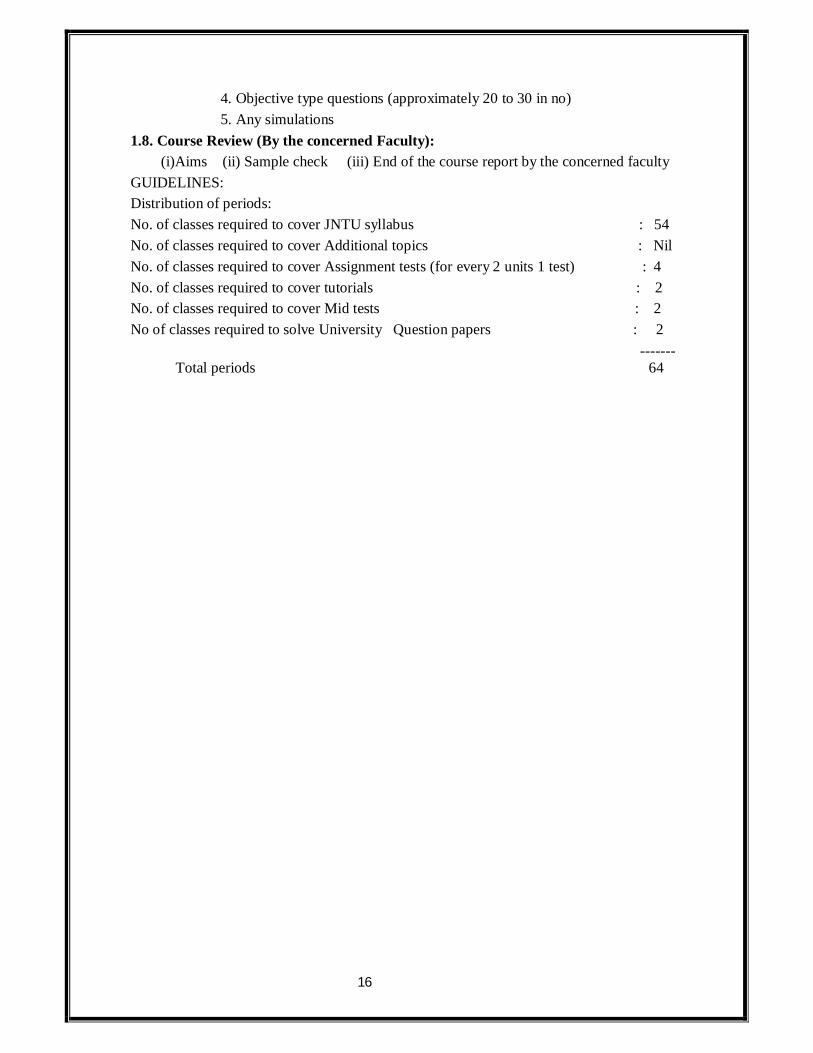
DEPARTMENT OF MECHANICAL ENGINEERING
INDIVIDUAL TIME TABLE
COURSE : II B.TECH NAME OF THE FACULTY:K RAJU SUB:KOM,ED II YR, ME-A,B 9.30-
10.20 10.20-11.10
11.10-12.00
12.00-12.50 12.50-1.30 1.30-
2.20 2.20-3.10
3.10-4.00
1 2 3 4 5 6 7 MON
ME-A
LUNCH
TUE
ME-B ME-B
WED EEE(ED)
ME-A
THU ME-B
ME-A
FRI EEE(ED)
ME-B
SAT ME-A ME-A
ME-B
SCOPE:
1. To provide in-depth knowledge in basic mechanisms
2. To learn the systematic way of solving problems 3. To understand the different methods of obtaining a mechanism
4. To efficiently implement the solutions for practical problems
EVALUATION SCHEME: PARTICULAR WEIGHTAGE MARKS
End Examinations 75% 75 Three Sessionals 20% 20 Assignment 5% 5 TEACHER'S ASSESSMENT(TA)* WEIGHTAGE MARKS *TA will be based on the Assignments given, Unit test Performances and Attendance in the class for a particular student.
20
GEETHANJALI COLLEGE OF ENGINEERING & TECHNOLOGY
CHEERYAL (V), KEESARA (M), R.R. DIST. 501 301
DEPARTMENT OF MECHANICAL ENGINEERING
SUBJECT: KINEMATICS OF MACHINERY
ASSIGNMENT QUESTIONS
UNIT-I: MECHANISMS AND MACHINES
1. Two shafts have their axes parallel and 2.5 cm apart. One of the shafts drives the other through an Oldham coupling. Sketch the arrangement and prove that the angular velocity ratio is unity. If the speed of the shaft is 100 rpm, what is the maximum velocity of sliding in cm per minute of the intermediate disc on either of the side discs? 2. What is meant by inversion of a mechanism? Describe with the help of suitable sketches the inversion of (a) Slider crank chain and (b) double slider chain. What are the different forms of quadric cycle chain? 3. (a) What is a Kinematic pair? State different methods of classifying them and state the salient features of each method of classification.
(b) What is the difference between quick return motion of crank and slotted lever type and that of Whitworth type? What is the ratio of time taken on cutting and return strokes? 4. (a) What are resistant bodies? Is it necessary that the resistant bodies be rigid? Give reasons for your answer.
(b) Describe elliptical trammels. How does it enable you to describe a true ellipse?
UNIT-II: STRAIGHT LINE MOTION MECHANISMS
1.(.a) Prove that the tracing point, giving the horizontal straight line motion in Tchebicheff mechanism, lies at the mid point of the coupler. (b) Prove that a point on one of links of a Hart mechanism traces a straight line on the
movement of its links?
21
2. (a) Under what conditions Scott-Russell mechanism traces out a straight line and an ellipse? State the limitations of Scott-Russell mechanism.
(b) Sketch a pantograph, explain its working and show that it can be used to reproduce to an enlarged scale a given figure.
3. (a) Show that the Peaucellier mechanism generates an exact straight line as its path.
(b) A circle has OR as its diameter and a point Q lies on its circumference. Another point P lies on the line OQ produced. If OQ turns about O as centre and the product OQ x OP remains constant, show that the point P moves along a straight line perpendicular to the diameter OR. 4. (a) Sketch a Peaucellier mechanism. Show that it can be used to trace a straight line.
(b) How can you show that a Watt mechanism traces an approximate straight line?
UNIT-III: KINEMATICS
1. (a) State and prove the Kennedy’s theorem as applicable to instantaneous centres of rotation of three bodies. How is it helpful in locating various instantaneous centres of a mechanism?
(b) In a four bar chain ABCD, AD is the fixed link 12 cm long, crank AB is 3 cm long and rotates uniformly at 100 r.p.m. clockwise while the link CD is 6 cm long and oscillates about D. Link BC is equal to link AD. Find the angular velocity of link DC when angle BAD is 600.
2. Prove Klein’s construction for determining the acceleration of a slider in a slider-crank mechanism. Hence show that the acceleration of the piston of an engine at inner and outer dead centre positions is given by

22
3. Refer to Figure.1. The following dimensions are given. O2A = 4cm, AB = 7cm, AO2 B = 450, ω2 = 25 rad/s cw. Determine the angular velocity of the connecting rod and velocity of piston. Also, determine the velocity of the center of gravity of the connecting rod which is at a distance of 3 cm from the crank pin A. Use the Instantaneous center method.
4. In a Whitworth quick return motion, a crank AB rotates about the fixed centre A. The end B operates a slider reciprocating in a slotted link, rotating about a fixed centre D, 5 cm vertically above A. The crank AB which is 10 cm long, rotates in a clockwise direction at a

23
speed of 100 r.p.m. Find the angular acceleration of the slotted link for the configuration in which AB has turned through an angle of 45 degrees past its lowest position.
(a) An Ackermann steering gear does not satisfy the fundamental equation of steering gear at all positions. Yet it is widely used. Why?
(b) Two shafts are to be connected by a Hooke’s joint. The driving shaft rotates at a uniform speed of 500 rpm and the speed of the driven shaft must lie between 475 and 525 rpm. Determine the maximum permissible angle between the shafts.
1.(a) An Ackermann steering gear does not satisfy the fundamental equation of steering gear at all positions. Yet it is widely used. Why?
(b) Two shafts are to be connected by a Hooke’s joint. The driving shaft rotates at a uniform speed of 500 rpm and the speed of the driven shaft must lie between 475 and 525 rpm. Determine the maximum permissible angle between the shafts.
2. (a) What conditions must be satisfied by the steering mechanism of a car in order that the wheels may have a pure rolling motion when rounding a curve? Deduce the relationship connecting the inclinations of the front stub axles to the rear axle, the distance between the pivot centres for the front axles and wheel base of the car.
(b) Give salient features of the speed of driven shaft of a Hooke’s joint by drawing a polar diagram.
3. (a) Derive an expression for the ratio of angular velocities of the shafts of a Hooke’s joint.
(b) Using Davis steering gear, find the inclination of the track arms to the longitudinal axis of the car if the length of car between axles is 2.3 m, and the steering pivots are 1.3 m apart. The car is moving in a straight path.
UNIT-IV: CAMS
1. (a) Explain the procedure to layout the cam profile for a reciprocating follower.
(b) Derive relations for velocity and acceleration for a convex cam with a flat faced follower.
2. Draw a cam profile which would impart motion to a flat faced follower in the following desired way. The stroke of the follower being 5 cm. (i) The follower to move with uniform acceleration upward for 900 , dwell for next 900, (ii) The follower to return downward with uniform retardation for 1200 and dwell for next 600. The minimum radius of the cam being 3 cm.
3. (a) Compare the performance of Knife –edge, roller and mushroom followers.
(b) A knife edged follower for the fuel valve of a four stroke diesel engine has its centre line coincident with the vertical centre line of the cam. It rises 2.5 cm with SHM during 600 rotation of cam, then dwells for 200 rotation of cam and finally descends with uniform acceleration and deceleration during 450 rotation of cam, the deceleration period being

24
half the acceleration period. The least radius of the cam is 5 cm. Draw the profile of the cam to full size.
4. A cam profile consists of two circular arcs of radii 24 mm and 12 mm joined by straight lines giving the follower a lift of 12 mm. The follower is a roller of 24 mm radius and its line of action is a straight line passing through the cam shaft axis. When the cam shaft has a uniform speed of 500 r.p.m., find the maximum velocity and acceleration of the follower while in contact with the straight flank of the cam.
UNIT-V: GEARING
1. (a) Make a comparison of cycloidal and involute tooth forms.
(b) Two 200 pressure angle involute gears in mesh have a module of 10mm. Addendum is 1 module. Large gear has 50 teeth and the pinion has 13 teeth. Does interference occur? If it occurs, to what value should the pressure angle be changed to eliminate interference?
2. (a) Sketch two teeth of a gear and show the following: face, flank, top land, bottom land, addendum, dedendum, tooth thickness, space width, face width and circular pitch.
(b) Derive a relation for minimum number of teeth on the gear wheel and the pinion to avoid interference.
3. Two gears in mesh have a module of 10 mm and a pressure angle of 250. The pinion has 20 teeth and the gear has 52. The addendum on both the gears is equal to one module. Determine (i) The number of pairs of teeth in contact (ii) The angles of action of the pinion and the wheel (iii) The ratio of the sliding velocity to the rolling velocity at the pitch point and at the beginning and end of engagement.
4. (a) What is a worm and worm wheel? Where is it used?
(b) Two 200 involute spur gears mesh externally and give a velocity ratio of 3. Module is 3 mm and the addendum is equal to 1.1 module. If the pinton rotates at 120 r.p.m. find: (i) The minimum number of teeth on each wheel to avoid interference. (ii) The number of pairs of teeth in contact.
Objective type questions:-
1) In a structure the degree of freedom is
a) 1 b) 2 c) d) 0
2) In a mechanism which one is true a) All links fixed b) one link fixed c) All links free d) None.
3) In a slider crank mechanism there are

25
a) Three links b) four links c) five links d) None 4) The links of a structure transmit
a) Forces only b) Motion only c) Both d) None 5) The links of a machine may transmit
a) Force only b) Motion only c) Power & Motion d) None
6) Hydraulic press is
a) Rigid link b) Flexible link c) Fluid link d) None 7) For a kinematic chain which relation is true
a) l = 2p - 4 b) l = 2f + 4 c) l = p – 4 d) l = p + 4 Where l = No. Of links & p = No. Of pairs
8) In a reciprocating steam engine, which of the following form a kinematic link a) Crank shaft & flywheel b) Cylinder & Piston
c) Piston & connecting rod d) Flywheel & engine frame
9) The Grueblen’s criterion for determining the degree of freedom of a mechanism having n links and p pair is given by
a) F = 3(n-1) – 2p b) F = 6( n-1)-2p
c) F = 5n-2p d) F = 3(n+1)-2p
10) Which of the following is the inversion of double slider crank chain
a) Beam engine b) Elliptical trammel c) Watts indicator mechanism d) Quick return motion mechanism
11) Kinematic pairs are those which have
a) Two elements that permit relative motion. b) Pair of elements held together mathematically
c) Pair of elements having line contact d) Pair of elements having surface contact
12) A 6-bar chain can be formulated to give constrained motion by using a) 5 turning pairs. b) 6 turning pairs.
c) 7 turning pairs. d) 8 turning pairs.
13) In a six bar chain for constrained motion there will be a) 6 binary links.
b) 4 binary & 2 ternary links. c) 5 binary & 1 ternary links.
d) 3 binary & 3 ternary links. 14) Which of the following mechanism is used to enlarge or reduce the size of a drawing
a) Pantograph

26
b) Graphometer c) Oacillograph
d) Clinograph 15) In a kinematic chain, if the specification of one coordinate or dimension or position
of a single link is sufficient to define the position of all other links , then the chain is called a kinematic chain of
a) 2 D.O.F b) 1 D.O.F
c) 3 D.O.F d) None
16) A negative degree of freedom for a linkage means a) Constrained motion of the linkage.
b) Un-Constrained motion of the linkage c) Any of the linkage
d) Statically indeterminate structure 17) A slider crank mechanism is a special case of a
a) 3- bar mechanism b) 2- bar mechanism
c) 6- bar mechanism d) 4- bar mechanism
18) The study of relative motion between the parts of a machine is called a) Static
b) Hydrodynamics c) Kinematics
d) Kinetics
19) The elements or links which are connected together in such a way that the relative motion is completely constrained, from a
a) Kinematic pair
b) Machine c) Mechanism
d) Kinematic chain 20) When two elements have point or line contact motion, the pair so formed is known as
a) Higher pair b) Lower pair
c) Screw pair
d) Closed pair

27
21) Which one of the following is an example of completely constrained motion a) Rotor of a vertical shaft turbine
b) A foot step bearing c) A shaft with collars at each end rotating in a round hole
d) A circular bar moving in a round hole
22) A spherical pair allows
a) 2 D.O.F b) 4 D.O.F
c) 1 D.O.F d) 3 D.O.F
23) A cylindrical pair allows a) 2 D.O.F b) 3 D.O.F
c) 4 D.O.F d) 1 D.O.F 24) A screw pair allows
a) 2 D.O.F b)3 D.O.F c) 5 D.O.F d)1 D.O.F
NUMERICAL PROBLEMS:
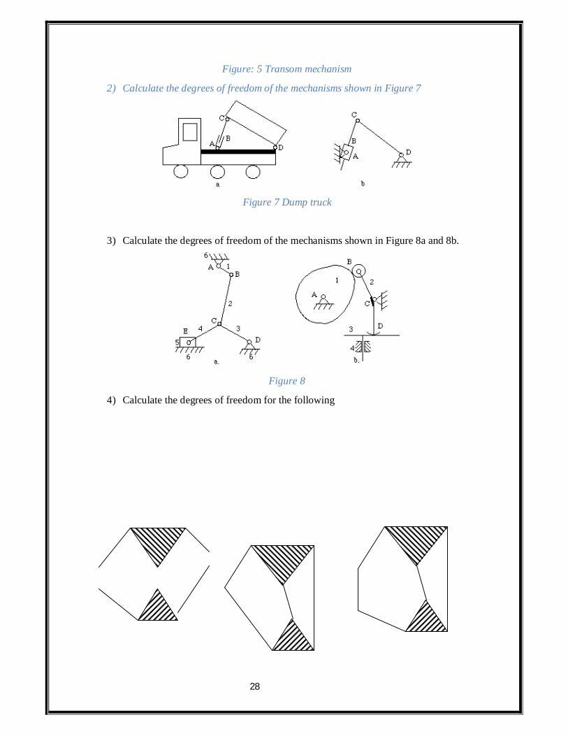
1) The transom mechanism of the door is shown in Figure 5-a. The opening and closing mechanism is shown in Figure 5-b. calculate its degree of freedom.
28
Figure: 5 Transom mechanism
2) Calculate the degrees of freedom of the mechanisms shown in Figure 7
Figure 7 Dump truck
3) Calculate the degrees of freedom of the mechanisms shown in Figure 8a and 8b.
Figure 8
4) Calculate the degrees of freedom for the following

29
5) In a crank and slotted lever quick return mechanism, the distance between the fixed centers is 240mm and the length of the driving crank is 120mm. Find the inclination of the slotted bar with the vertical in the extreme position and the time ratio of cutting stroke to the return stroke. If the length of the slotted bar is 450 mm, find the length of stroke if the line of stroke passes through the extreme positions of the free end of the lever.
6) In a quick return mechanism the driving crank is 30mm long, and the time ratio of the working stroke to the return stroke is to be1.7, length of the working stroke is 120mm, determine the length of the slotted lever.
7) In a with worth quick return motion mechanism, the distance between the fixed centers is 50mm and the length of the driving crank is 75mm, the length of the slotted lever is 150mm and the length of the connecting rod is 135mm. Find the time of cutting stroke to the time of return stroke and also the length of the stroke.
UNIT –II (Straight Line Motion Mechanism)
Learning Objects:
By the end of Unit –II, the student should be able to
Write the need of straight line motion mechanisms
List out different exact and approximate straight line motion mechanisms
Write principle of exact straight line motion mechanisms.
Write how straight line motion can be obtained with the help of peancellar and hart
mechanisms
Write the use of pantograph.
Draw the sketch of pantograph and write how a given path can be copied (Either to
reduce scale or to enlarge scale) with the help of pantograph.
Draw the sketches of Scott Russell mechanism, croon hopper mechanism revert
mechanism, Tihebicff’s mechanism.

30
Essay Questions:
1. What is a photograph? Show that it cans producer paths exactly similar to the ones
traced out by a point on a link on an enlarged or reduced scale.
2. Enumerate straight line mechanism. Why are they classified in to exact and
approximate straight line mechanism?
3. Sketch a peancellar mechanism. Show that it can be used to track a straight line.
4. Prove that a point on one of links of a hart mechanism traces a straight line on the
movement of its links.
5. What is Scott Russell mechanism? What are its limitations? How it is modified?
6. In what way Group hopper mechanism is the derivation of modified Scott Russell
mechanism.
7. How can you show that watt mechanism traces on approximate straight line?
8. How can we ensure that a Tchebielf’s traces on approximate straight line?
9. Discuss Robert mechanism.
10. What are straight line mechanisms? 11. What are the different types of exact straight line motion mechanisms and explain
each of them. 12. What are the different types of approximate straight line motion mechanisms and
explain each of them. 13. Explain briefly Scott Russel mechanism for tracing a straight line?
14. Write short notes on Peaucellier and Hart straight line motion mechanisms
Objective Questions:
1. In pantograph all the pairs are
[ ]
(a) Turning pairs (b) Sliding pairs
(c) Spherical pairs (d) Self closed pairs.
2. Which of the following mechanism is made up of turning pairs only?
[ ]
(a) Scotch Russell mechanism (b)Peancellar mechanism

31
(c) Both (d) None
3. Which of the following is used to enlarge or reduce site of a drawing? [
]
(a) Groan hopper mechanism (b) Watts mechanism
(c) Pantograph (d) None
4. Which of the following is derivation of modified Scott Russell mechanism?
[ ]
(a) Groan hopper mechanism (b) Watts mechanism
(c) Pantograph (d) None
5. Peancellar mechanism has got _____________no of links.
[ ]
a) 2 (b) 4 (c) 6 (d) 8
6. Heart mechanism has got _____________no of links.
[ ]
a) 2 (b) 4 (c) 6 (d) 8
7. Which of the following is an exact straight line motion mechanism?
[ ]
a) Heart mechanism (b)Robert mechanism
c) Modified Scott Russell mechanism (d) None
8. Which of the following of approximate straight line motion mechanism?
[ ]
a) Peancellar mechanism (b) Hart mechanism
c) Modified Scott Russell mechanism (d) None
9. Which of the following is a coping mechanism
[ ]
a) Peancellar mechanism (b) Hart mechanism
c) Modified Scott Russell mechanism (d) None
UNIT-III - Velocity and Acceleration Analysis
Learning Objects:
32
By the end of Unit-III, the student should be able to
Compute Velocity, centripetal and tangential acceleration of a rotating link
(Both in magnitude and direction)
Compute Velocity and acceleration of a sliding link (Both in magnitude and
direction)
Draw the Velocity diagram of a given mechanism.
Draw the acceleration diagram of a given mechanism.
Compute Velocities, angular Velocities, acceleration and angular acceleration of
various likes of mechanisms.
Define instantaneous centre, types of instantaneous centers.
State and prove Kennedy’s the arm
Apply Kennedy’s theorem to locate instantaneous centers of a given mechanism
and compute Velocity from it.
State importance of corioli’s component of acceleration.
Compute magnitude and direction of corioli’s component of acceleration and use
it in drawing acceleration diagrams.
List out the mechanisms where corioli’s component of acceleration exists
Draw Klein’s construction.
Compute Velocities and accelerations of various links of a single slider crank
chain from Klein’s construction.
Derive the expression for displacement, Velocity and acceleration of slider of a
single slider crank chain.
Essay Questions:
1. What is a configuration diagram? What is it we?
2. Describe the procedure to construct velocity diagram of a four bar linkage.
3. What is velocity image? State why it is known as helpful device in velocity analysis
of complicated linkage.
4. What is velocity of rubbing? How it is found?
5. What do you mean by the term coincident point?

33
6. What is instantaneous centre? How do you know the number of instantaneous centers
of a mechanism?
7. State ad prove Kennedys theorem as applicable to instantaneous centre of rotation of
three bodies How it i) useful in locating various instantaneous centre of a mechanism.
8. What do you mean by cent rode of a body? What are its types? (or) Define space cent
rode and body cent rode.
9. In a slider crank mechanism, stoke of the slider is half of length of connecting rod.
Draw a diagram to give velocity of slider at any instant assuming creak shat turns
unifenly.
10. Show that plane motion of a rigid body relative to another rigid body is equalent to
rolling motion of one cent rode or the other.
11. State and explain angular velocity ratio theorem as applicable to mechanism.
Objective Questions:
1. For a rotating link, the direction of velocity vector is __________ [
]
a. a)Parallel to link b) ┴ r to link c) 450 to link d) None
2. For a rotating link the direction of centripetal acceleration is _____ [
]
a. a)Parallel to link b) ┴ r to link c) 450 to link d) None
3. For a rotating link the direction of tangential acceleration is ____ [
]
a. a)Parallel to link b) ┴ r to link c) 450 to link d) None
4. For a slider the sliding velocity direction is _____ _
a. a)Parallel to sliding path b) ┴ r to sliding path c) 450 to sliding path
d) None
5. For a slider the sliding acceleration direction is _______ [
]

34
a. a)Parallel to sliding path b) ┴ r to sliding path c) 450to sliding path
d) None
6. Velocity of point ‘A’ is_____________________ [
]
a) rw b) w2r c) rα d) None
7. Centripetal acceleration of point ‘A’ is ________ [ ]
[a)rw b) w2r c) rα d) None
8. Tangential acceleration q point ‘A’ is__________ [
]
a. a)rw b) w2r c) rα d) None
9. A pin of a radius ‘r’ is connecting two links that are rotating with angular velocities
a. ‘w1 and w2 in opposite direction then rubbing velocity at pin is ___ [
]
b. a)(w1- w2) r b) (w1+w2) r c) r d) None
10. A pin of radius ‘r’ is connecting two lines that are rotating with angular velocities w1
and w2, in same direction then rubbing velocity at pin is ______
[ ]
a. a)(w1- w2) r b) (w1+w2) r c) r d) None
11. If wA wB be angular velocities of input and output links of a four bar mechanism
a. then ‘n’ of mechanism _______________
[ ]
12. If ‘n’ is the number of links of a mechanism then number of instantaneous center is
____
a) b) c) d) None [
]
13. According to Kennedy’s theorem, if three bodies move relative to each other,
a. their instant each centers will lie on a_____
[ ]
b. a)Straight line b) Parabolic curve c) Ellipse d) None

35
14) The instances centre that remains in same place for all configuration of the
c. mechanism is known as _____________
[ ]
d. a)Permanent instance b) Fixed instances centre
e. c)Both fixed and permanent d) None
15. The instantaneous centre that varies with configuration of mechanism is ____ [
]
a)Permanent b) Fixed centre c) Both fixed and Permanent d) None
16. When a slider is sliding along the straight path its instantaneous centre lies at __[
]
a)At’ ∞’ parallel to path b) At ‘α’ ┴ r to path
c)At content point between slider an path d) None
17 When a slider moves an a fixed link having curved surface, then instantaneous centre
f. lies at _________________
[ ]
a)At point of constant b) At centre of curvature
c)At ∞ tangential to circular curvature d) None
18. Number of instantaneous centers of a under mechanism are _______ [
]
a)2 b) 4 c) 6 d) None
19. Number of instantaneous centre q a single slider crank chair are_____ [
]
a)2 b) 4 c) 6 d) None
20. Number of instantaneous centre of double slider crank chair are ____ [
a) 2 b) 4 c) 6 d) None
21. Which of the following mechanism have carioles complaint of acceleration___ [
]
g. a) Four bar linkage b) Quite return motion mechanism of
shaper

36
h. c) Elliptical trammel d) None
22. Which of the following mechanism do not have carioles of acceleration? [
]
i. a) Four bar linkage b) Crank and slotted
lever mechanism
ii. c) Whit worth acceleration motion mechanism d) None
23. In a whit worth mechanism, the angle turned by crank during return stroke (Idle
iii. Stroke) is 900then ratio of time of cutting to ret urn stroke is_____
[ a)3 b) 1/3 c) 1 d)
None
24. When a crank rotates with uniform angular velocity them tangential
i. component of acceleration is ______________.
[ ]
25. In a whit worth mechanism the slotted line is rotating with angular velocity ‘w’ in
clank wise direction and slider slides along slotted link with velocity ‘V’ then
i) Magnitude of cariole complaint of acceleration is________________ [
a) b) 2vw c) vw d)
ii) Direction of coriolis comport of acceleration is__________________
[
a) Parallel to slotted to link b) ┴ r to slotted link
c) Inched to slotted link d) None
26. If r = crow radius, l = connects rod length n= Q= angle mode by crank with 2DC
W= angle of velocity of f crank
i. Expression for displacement of slider is _____________________
ii. Expression for velocity of slider is _________________________
iii. Expression for acceleration of slider is _____________________
27. Scale for Klein’s velocity diagram is _______________________________
28. Scale for Klein’s acceleration diagram of___________________________

37
29. Klein’s constriction is used only for _______________________________ [ ]
j. a) Four bar chain b) single slider crank chair
k. c) Double slider crank chair d) whit worth mechanism
30. Klein’s Velocity diagram is ____________________________________ [
]
l. a) Rectangle b) Velocity c) Square d) None
31For a rigid link, velocity of one end relative to other end of the link will be
m. Parallel to the link n. Perpendicular to the link
o. At center of circle p. On their point of contact
32) Linear velocity of a point on a link relative to any other point on the links will be
q. Parallel to line joining the two points r. Perpendicular to the line joining the two points
s. Perpendicular to lower end of the link t. None
33) Acceleration of any point in a mechanism is determined by
u. Analytical method v. Graphical method
w. Both x. None
34) Component of acceleration parallel to the velocity of the particle at the given instant is known as
y. Radial component
z. Tangential component
aa. Coriolis component bb. None
35) When a point on a link moves along a straight line, its acceleration will only have
a. Radial component
b. Tangential component c. Coriolis component
d. All of the above

38
36)The sense of tangential acceleration of a link is
e. same as that of velocity
f. opposite to the velocity g. can be either same or opposite to velocity
h. None 36 Direction of tangential acceleration is
a. along the angular velocity b. opposite to the angular velocity
c. Both d. Perpendicular to the angular velocity
37 Component of acceleration, perpendicular to the velocity of the particle, at a given instant is known as
a. Radial component b. Tangential component
c. Coriolis component d. All of the above
38 Radial & Tangential component of a particle at any instant will be a. Parallel to each other
b. Opposite to each other c. Perpendicular to each other
d. At 450 to each other 39 When end point of a link moves with constant angular velocity, its acceleration will
have only a. Radial component
b. Tangential component c. Coriolis component d. All of the above
40 A point ‘B’ on a rigid link moves with respect to ‘A’ with angular velocity w rad/sec of link AB about A, the radial component of the acceleration of B with respect to A, is
41 a) V2ba b) Vba c) Vba . AB d) V2
ba . AB
i. AB AB 42 Where Vba is linear velocity of B with respect to A
43 In a rigid link AB, the point B moves with respect to A . The angular acceleration of link AB will be equal to
a) Radial acceleration b) Tangential acceleration

39
c) Total acceleration d) none
44 If a particle of a link has a velocity which changes both in magnitude & direction at any instant, then it must have components of acceleration
a. Centrifugal & tangential
b. Centripetal, centrifugal & tangential c. Centripetal, centrifugal & gravitational
d. Centripetal, centrifugal, gravitational & tangential 45 The tangential component of acceleration of the slider with respect to the coincident
point on the link is known as a. Radial component
b. Tangential component c. Coriolis component
d. None 46 The Coriolis component of acceleration acts
a. Parallel to the sliding surface b. Perpendicular to the sliding surface
c. At 450 to the sliding surface d. None
47 The coriolis component of acceleration will exist if any of the two coincidental points a. have same center of rotation
b. have relative angular velocity of sliding c. have linear relative velocity of sliding accompanied by the rotation about
fixed centers d. none
48 According to the coriolis law if a point moves along a path having rotation, the absolute acceleration of the point is equal to the
a. Absolute acceleration of the point relative to coincident point in the path. b. Absolute acceleration of the coincident point in the path
c. Coriolis component acceleration d. Vector sum of a, b & c above.
49 The direction of coriolis component of acceleration is the direction of relative velocity vector for the two coincidental points as rotated by 900 in the direction of angular velocity of rotation of the link
a. rotated by 900 in the direction of angular velocity of rotation of the link
b. rotated by 1800 in the direction of angular velocity of rotation of the link c. in the direction directly opposite to that of angular velocity

40
d. None 50 The coriolis component of acceleration leads the sliding velocity by
a. 300 b. 450
c. 900
d. 1800
51 The coriolis component of acceleration exist when a point moves along a path which has
a. Rotational motion b. Linear motion
c. Tangential acceleration d. Gravitational acceleration
52 If a slider moves with a velocity v on a link revolving at angular velocity ω, the magnitude of coriolis component of acceleration is
53 a) Vω b) 2Vω c) 2 Vω d) Vω/2 54 The coriolis component is encountered in
a. Slider crank mechanism b. 4-bar chain mechanism
c. Quick return mechanism d. All of the above
55 The coriolis component exist in a. Shaper mechanism
b. Tangent cam mechanism c. Link sliding in a swiveling pin
d. All of the above 56 Coriolis component is considered if
a. The point considered moves on a path that rotates b. The point considered moves along a path that is stationary
c. The point considered moves along a circular path
d. The point considered moves in any curvilinear path
57 If a point moves along a straight line which is rotating, then the tangential component of acceleration is
58 a) v2/r b) dv -ω2r c) dv/dt d) 2vω + r 1. dt
59 A slider sliding at 10cm/sec on a link, which is rotating at 60 rpm, is subjected to coriolis acceleration of magnitude

41
a. a) 40 2 cm/s2 b) 0.4 cm/s2 c) 40 cm/s2 d) 4 cm/s2
60 The component of acceleration parallel to the link is called
a. Radial b. Tangential
c. Coriolis d. Absolute
61 When the crank rotates with uniform speed, it has a. Only radial acceleration
b. Only tangential acceleration c. Only Coriolis acceleration
d. None 62 The total number of instantaneous centers for a mechanism containing n links is
given by a. a) (n-1)/2 b) n(n-1)/2 c) n d) n/2
63 If three bodies move relative to each other then according to Kennedy’s theorem their instantaneous center will lie on
a. Parabolic curve b. Ellipse
c. Circle
d. Straight line
64 The relative instantaneous center of two bodies having a point of contact, lies a. At the point of contact
b. On the common tangent c. On the common normal
d. None 65 Two links are said to have a pure rolling contact if their instantaneous center lies
a. On their point of contact b) At the center of curvature b. c) At the pin joint d) At infinity
66 Property of instantaneous center is a. Rigid link rotates instantaneously relative to another link at the instantaneous
center for the configuration of the mechanism considered b. Two rigid links have the same linear velocity relative to the third rigid link
c. Two rigid links have no linear velocity relative to each other at the instantaneous center
d. All of the above

42
67 Magnitude of velocities of the points on a rigid link is inversely proportional to the distance from the points to the instantaneous center and is
a. Perpendicular to the line joining the point to the I.C b. Parallel to the line joining the point to the I.C
c. All of the above d. None
68 Instantaneous centers which remain in the same plane for all configuration of the mechanism, are known as
a. Fixed I.C b. Permanent I.C
c. Neither fixed nor permanent I.C d. None
69 I.C which move on the mechanism, moves but joints are of permanent nature, are known as
a. Fixed I.C
b. Permanent I.C
c. Neither fixed nor permanent I.C d. None
70 I.C which vary with the configuration of mechanism, are known as a. Fixed I.C
b. Permanent I.C c. Neither fixed nor permanent I.C
d. None 71 When a slider moves as a fixed link having curved surface, their instantaneous center
lies
a. On their point of contact
b. At the center of curvature c. At the pin joint
d. At infinity 72 When two links are connected by a pin joint their I.C lies
a. On their point of contact b. At the center of curvature
c. At the pin joint d. At infinity
73 When a slider moves as a fixed link having straight surface, their instantaneous center
a. On their point of contact b) At the center of curvature

43
b. c) At the pin joint d) at infinity 74 When a slider moves as a fixed link having constant radius of curvature will have its
I.C a. At the pin joint
b. At infinity c. On their point of contact
d. At the center of circle 75 Klein’s construction gives a graphical construction for
a. Acceleration polygon b. Velocity polygon
c. Angular polygon d. All of the above
76 Klein’s construction is used to determine a. Displacement of various parts
b. Acceleration of various parts
c. Velocity of various parts
d. Angular acceleration of various parts 77 Klein’s construction is used when crank has a
a. Uniform angular velocity b. Non uniform angular velocity
c. Non uniform angular acceleration d. Uniform angular acceleration
Numerical Problems:
1. In a four link mechanism, the dimensions of links are as under; AB=50 mm; BC=66
mm; CD=56 mm and AD=100 mm. At the instant when ALDAB=600, the link ‘AB’
has angular Velocity of 10.5 rod /Sec in counter clock wise direction and has a
retardation of 26 rod/Sec. Determine
(i) Velocity of point ‘C’.
(ii) Velocity of point ‘E’ on link ‘BC’ when BE=40 mm.
(iii) Angular Velocities of link ‘BC’ and ‘CD’.
(iv) Velocity of an offset point ‘F’ on link ‘BC’ if BF=45 mm, CF=30 mm and
BCF is read clock wise.

44
(v) Velocity of an offset point ‘G’ on link ‘CD’ if CG=24 mm, DG=44 mm and
DCG is read clock wise.
(vi) Velocity of rubbing at pins A, B, C and D when rods of pins are 30, 40, 25
and 35 mm respectively.
(vii) Angular acceleration of links ‘BC’ and ‘CD’.
(viii) Linear acceleration of points ‘E’,’F’ and ‘G’.
2. In a slider crank chain mechanism, the crank is 480 mm long and rotates at 20 rod/sec
in counter clock wise direction. Length of connecting rod is 1.6m. When crank turns
600 from IDC determine.
(i) Velocity of slider.
(ii) Velocity of point ‘E’ located at a distance of 450 mm on the connecting rod
extended.
(iii) Acceleration of slider at ‘B’.
(iv) Acceleration of point ‘E’.
(v) Angular acceleration of link ‘AB’.
3. An engine crank shaft drives a retroaction pump through a mechanism a shown in fig.
The crank rotates at 160 rpm in clock wise direction diameter of pump piston at ‘F’ is
200 mm, Dimensions of various link are 0A=170mm, AB=660, BC=510 mm,
CD=170mm, DE=830mm for the position of crank shown in diagram determine.
(i) Velocity of cross head at E.
(ii) Velocity of rubbing at ins A,B,C & D, the diameters being 40,30,30 and 50
mm respectively.
(iii) Forque required at shaft ‘O’ to overcome a pressure of 300 km/m2 at pump
piston ‘F’.

45
4. For the whit worth quick return mechanism shown in figure, the dimensions of links
are; OP (crank) =240 mm, OA=150 mm, AR=165 mm, RS=430 mm. the crank
rotates at an angular velocity of 2.5 rod/sec. At the movement when the crank makes
an angle of 450 with vertical, calculate
(i) Velocity of ram’s
(ii) Velocity of slider ‘P’ on slotted lever.
(iii) Angular velocity of link ‘RS’
5. For the crank slotted lever mechanism shown in fig. determine acceleration of ram
‘D’ of crank rotates at 120 rpm in anti clock wise direction. Also determine angular
acceleration of slotted link given AB=150mm, slotted are =OC=700mm, link
CD=200mm.
46
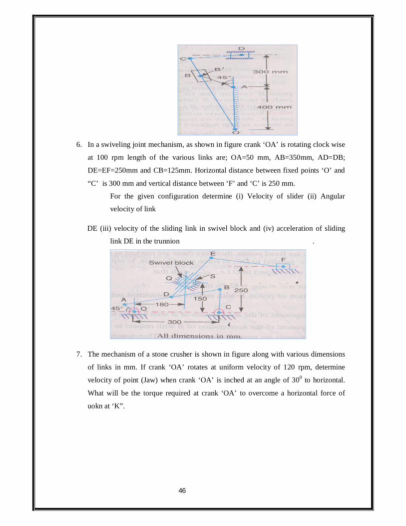
6. In a swiveling joint mechanism, as shown in figure crank ‘OA’ is rotating clock wise
at 100 rpm length of the various links are; OA=50 mm, AB=350mm, AD=DB;
DE=EF=250mm and CB=125mm. Horizontal distance between fixed points ‘O’ and
“C’ is 300 mm and vertical distance between ‘F’ and ‘C’ is 250 mm.
For the given configuration determine (i) Velocity of slider (ii) Angular
velocity of link
DE (iii) velocity of the sliding link in swivel block and (iv) acceleration of sliding
link DE in the trunnion .
7. The mechanism of a stone crusher is shown in figure along with various dimensions
of links in mm. If crank ‘OA’ rotates at uniform velocity of 120 rpm, determine
velocity of point (Jaw) when crank ‘OA’ is inched at an angle of 300 to horizontal.
What will be the torque required at crank ‘OA’ to overcome a horizontal force of
uokn at ‘K”.

47
8. In the pump mechanism shown in figure, OA= 320mm, AC=680 mm, OQ=650mm.
for the given configuration determine.
(i) Angular velocity of slider
(ii) Sliding velocity of plunger
(iii) Absolute velocity of plunger if crank rotates at 20 rod be clock wise.
Also determine linker acceleration of slider ‘C’
9. Determine velocity of slider ‘E’ in the problem 3 by instantaneous centre method.
10. In a pin jointed u bar mechanism, AB= 300mm, BC=CD=360mm and AD=600 mm,
(fixed link). LBAD=600 other crank rotates at a speed of 100 rpm. Locate all
instantaneous centers and determine angular velocity of link ‘BC’.
11. For a single slider crank mechanism, crank OB=100mm, connecting rod
AB=400mm. If crank rotates at an angular velocity of lorod/Sec clock wise, find (i)
velocity of slider ‘A’ and angular velocity of connecting rod AB use instantaneous
centre method and LAOB=450.
12. Type question

48
13. Figure shows configuration of whit worth quick return mechanism. Length of
fixed link ‘OA’ and crank ‘OP’ are 200 mm and 350mm respectively. Other lengths
are AR=200mm AND RS=400mm. find velocity of ram using instantaneous centre
method when crank makes an angle of 1200 with fixed link and has angular velocity
of 10rod/Sec.
14. For the crank and slotted lever quick returns motion mechanism of shaper
shown in figure-3 (problem.5) determine velocity of ram ‘D’ using instantaneous
centre method.
15. Figure shows mechanism of sewing machine needle box. For the given
configuration, find velocity of needle fixed to slider ‘D’ when crank ‘OA’ rotates at
40 rod/Sec.
16. For a single slider crank chain mechanism, crank OB=100mm, connecting rod
AB=400mm. if the crank rotates at an angular velocity of 10 rad/Sec clockwise.
Determine velocity and acceleration of slider by Klein’s construction method.
UNIT –V -GEARS
Learning Objects:
By the end of Unit-IV, the student should be able to
State the use and applications of universal coupling.
Derive the expression for ratio of shaft velocities (I/P and output)

49
Derive the condition for equal speeds of driving and driven shafts.
Compute maximum and minimum output shaft Velocities.
Derive expression for angular acceleration of driven shaft.
Solve the numerical problems related to universal coupling.
State the drawback of single Hooks Joint (Universal Coupling)
Draw the sketch of double Hooks joint.
Write how drawback with single Hooks joint cam be eliminated in double
Hooks joint
State condition for steering gear mechanism.
List out different types of steering gear mechanism.
Draw the sketches of Davis and Ackerman’s steering gear mechanism.
Essay Questions:
1. What is Hooks joint? State its application.
2. Derive the expression for ratio of shall velocities.
3. What is the drawback of universal coupling and how it can be overcame?
4. Explain why two Hooks joint are used for trant motion from engine to differential
of automobile.
5. Draw the polar diagram depicting salient features of driven shall speed and derive
the condition for equal of driving and driven shall for a universal coupling.
6. Describe double hooks joint and explain what happens if the forks attached to
intermediate shaks are in perpendicular planes.
7. What is fundamental equation of steering gear? Which steering gear full fills this
condition?
8. An Ackerman steering gear doesn’t satisfy fundamental equation of steering yet it
is widely used shy?
9. Describe functioning of Davis steering gear and obtain the condition for correct
steering in case of Davis steering gear.
10. Compare Davis steering gear and Ackerman steering gear.
Objective Questions:
1. For one complete rotation of driving shaft, how many times the speeds of driving

50
and driven shaft will be equal.
[ ]
a) 1 (b) 2 (c) 3 (d) 4
2. For connecting two shafts which are inched at small angles __coupling is used. [
]
a) Oldham (b) Universal (c) Muff (d) None
If ‘n’ is the speed of driving shaft of a universal coupling and ‘x’ is the between
driving and driven shaft then
3. Maximum speed of driven shaft.
[ ]
a) N Cos (b) (c) N cos2 (d) N
4. Minimum speed of driven shaft.
[ ]
a) N Cos (b) (c) N cos2 (d) N
5. Maximum fluctuation is speed of universal coupling is _____________ [
]
a) W Sin Cos (b) W Tan Sin (c) W Cos (d)
6. Condition for equal speeds of driving shaft and driven shaft of a universal
coupling is __________
[ ]
a) Tan = (b) Tan = (c)Tan = (d)
None
7. Application of universal coupling is ______________
[ ]
8. In automobiles _____________coupling is used to connect gear box and
differential
9. In multiple spindle drilling machine __________________________ coupling is
used.
10. ________________coupling is used in horizontal column and kineme milling
machine.
11. Disadvantage of single Hooks joint is ________________________.

51
In double hooks joint forks of intermediate shafts are in same plane. If speed of driving
shaft is ‘n’ and angle between intermediate shaft and output shaft is than
12. Maximum speed of intermediate shaft is ________
[ ]
a) N Cos (b) (c) (d) N
13. Minimum speed of intermediate shaft is ________
[ ]
a) N Cos (b) (c) (d) N
14. Maximum speed of output shaft is _____________
[ ]
a) N Cos (b) (c) (d) N
15. Minimum speed of output shaft is _____________
[ ]
a) N Cos (b) (c) (d) N
In double Hooks joint if the forks attached to intermediate shaft are in perpendicular plane and if speed of driving shaft is ‘n’ then
16. Maximum speed of intermediate shaft is _______
[ ]
a) N Cos (b) (c) (d) N
17. Minimum speed of intermediate shaft is _______ [
]
a) N Cos (b) (c) (d) N
18. Maximum speed of output shaft is ____________
[ ]
a) N Cos (b) (c) N Cos2 (d)
52
19. Minimum speed of output shaft is ____________
[ ]
a) N Cos (b) (c) N Cos2 (d)
20. _____________________type of steering gear has only tanning pairs.
21. _________________________type of steering gear has sliding pairs.
22. _______________steering gear satisfies the condition for correct steering
perfectly.
23. Condition for correct steering gear is _________________________.
24. ________________________________steering gear is widely used.
Numerical Problems:
1. Two inclined shafts are connected by means of a universal joint. Speed of
driving shaft is 100 rpm. If total fluctuation of speed is not to exceed 12.5% of
means speed, what is the maximum possible inclination between the shafts.
With this angle what will be maximum acceleration to which driven shaft is
subtracted to and when this will occur.
2. Angle between axes of two shafts connected by Hooks joint is 180, determine
angle turned by driving shaft when velocity ratio is maximum and unity.
3. A Hooks joint connects two shafts whose axes are inclined at 1500. Driving
shafts rotates at 120 rpm driven shaft operates against a steady torque of 150
numbers and carries a flywheel whose mass is 45 kg with radius of gyration of
150mm. find maximum torque which will be exerted by driving shaft.
4. Driving shaft of Hooks joint runs at 240 rpm and angle between shafts is 200.
Driven shaft when attached mass 5.5 kg and radius of gyration of 150mm.
(i) If steady torque of 200 numbers resist rotation of driven shaft, find torque
exerted at driving shaft when Q=450.
(ii) At what valve of ‘ ’ will total fluctuation be limited to 24 rpm.
5. A double Hooks joint is used to connect two shafts in same plane.
Intermediate shaft is inclined at 200 to driving shaft as well as driven shaft. Find
maximum and minimum speeds of intermediate shaft and driven shaft, if driving
shaft has a constant speed of 2500 rpm.

53
6. The ratio between width of from axis and that of wheel base of a steering
mechanism is 0.4m. At the instant when front inner wheel is turned by 180, what
should be the angle turned by outer front wheel for perfect steering.
7. In a Davis steering gear, the length of the car between axles is 2.4m and steering pivots are
1.35m apart. Determine inclination of track arms to longitudinal axis of car when car moves
in a straight path.
8. The track arms of a Davis steering gear is at a distance of 192mm from front main axle where as the difference between their lengths is 96mm. if the distance between steering portly of main axle is 1.4m, determine the length of chaise between front and rear wheels. Also find inclination of track arm to longitudinal axis of vehicle.