Embed Size (px)
DESCRIPTION
manual
Citation preview
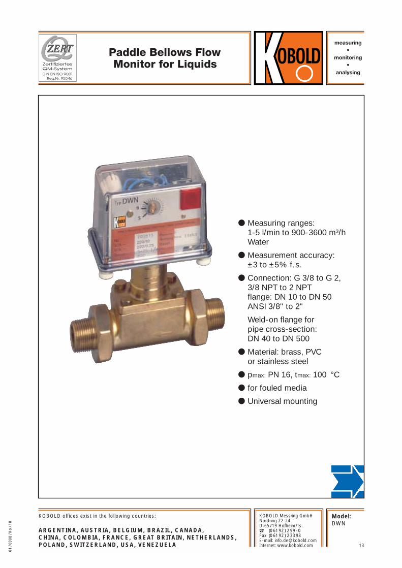
Paddle Bellows FlowMonitor for Liquids
measuring•
monitoring•
analysing
Model:DWN
13
KOBOLD offices exist in the following countries:
ARGENTINA, AUSTRIA, BELGIUM, BRAZIL, CANADA, CHINA, COLOMBIA, FRANCE, GREAT BRITAIN, NETHERLANDS, POLAND, SWITZERLAND, USA, VENEZUELA
KOBOLD Messring GmbHNordring 22-24D-65719 Hofheim/Ts.� (06192) 299-0Fax (06192) 23398E-mail: [email protected]: www.kobold.com
● Measuring ranges:1-5 l/min to 900-3600 m3/h Water
● Measurement accuracy: ±3 to ±5% f.s.
● Connection: G 3/8 to G 2, 3/8 NPT to 2 NPT flange: DN 10 to DN 50 ANSI 3/8" to 2"
Weld-on flange for pipe cross-section: DN 40 to DN 500
● Material: brass, PVC or stainless steel
● pmax: PN 16, tmax: 100 °C
● for fouled media
● Universal mounting
01 /
0908
/ K
o / 1
0
14 No responsibility taken for errors; subject to change without prior notice.
www.kobold.com
Paddle Bellows Flow Monitor for Liquids Model DWN
Brass Stainless steel PVC
Brass Stainless steel PVC
Steel zinc-plated Stainless steel PVC
Steel sprayed Stainless steelBoring pipe
box PVC
Brass Stainless steel Stainless steel
Stainless steel Stainless steel Stainless steel
FPM FPMFPM
T piece
Connecting thread
Connecting flange
Weld-on flange
Paddle system
Bellows
Seals
Stainless steel Stainless steel Stainless steel
Polycarbonate Polycarbonate Polycarbonate
100°C 100°C 20°C (60°C)
Case meas. section
Covering hood
tmax*
*Higher upon request
Description
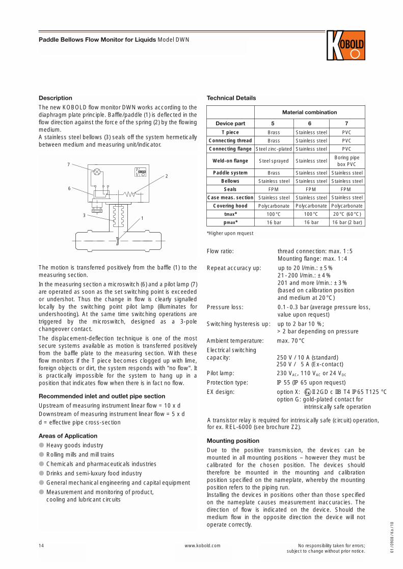
The new KOBOLD flow monitor DWN works according to thediaphragm plate principle. Baffle/paddle (1) is deflected in theflow direction against the force of the spring (2) by the flowingmedium.A stainless steel bellows (3) seals off the system hermeticallybetween medium and measuring unit/indicator.
16 bar 16 bar 16 bar (2 bar)pmax*
Flow ratio: thread connection: max. 1 :5Mounting flange: max. 1 :4
Repeat accuracy up: up to 20 l/min.: ±5%21-200 l/min.: ±4%201 and more l/min.: ±3%(based on calibration position and medium at 20°C)
Pressure loss: 0.1-0.3 bar (average pressure loss, value upon request)
Switching hysteresis up: up to 2 bar 10 %; > 2 bar depending on pressure
Ambient temperature: max. 70°C
Electrical switching capacity:
Pilot lamp: 230 VAC, 110 VAC or 24 VDC
Protection type: IP 55 (IP 65 upon request)
EX design: option X: II 2GD c IIB T4 IP65 T125 °C option G: gold-plated contact for
intrinsically safe operation
A transistor relay is required for intrinsically safe (circuit) operation, for ex. REL-6000 (see brochure Z2).
7
6
31
2
The motion is transferred positively from the baffle (1) to themeasuring section.
In the measuring section a microswitch (6) and a pilot lamp (7)are operated as soon as the set switching point is exceededor undershot. Thus the change in flow is clearly signalledlocally by the switching point pilot lamp (illuminates forundershooting). At the same time switching operations aretriggered by the microswitch, designed as a 3-polechangeover contact.
The displacement-deflection technique is one of the mostsecure systems available as motion is transferred positivelyfrom the baffle plate to the measuring section. With theseflow monitors if the T piece becomes clogged up with lime,foreign objects or dirt, the system responds with "no flow". Itis practically impossible for the system to hang up in aposition that indicates flow when there is in fact no flow.
Recommended inlet and outlet pipe section
Upstream of measuring instrument linear flow = 10 x dDownstream of measuring instrument linear flow = 5 x dd = effective pipe cross-section
Mounting position
Due to the positive transmission, the devices can bemounted in all mounting positions – however they must becalibrated for the chosen position. The devices shouldtherefore be mounted in the mounting and calibrationposition specified on the nameplate, whereby the mountingposition refers to the piping run.Installing the devices in positions other than those specifiedon the nameplate causes measurement inaccuracies. Thedirection of flow is indicated on the device. Should themedium flow in the opposite direction the device will notoperate correctly.
Areas of Application
● Heavy goods industry
● Rolling mills and mill trains
● Chemicals and pharmaceuticals industries
● Drinks and semi-luxury food industry
● General mechanical engineering and capital equipment
● Measurement and monitoring of product, cooling and lubricant circuits
Material combination
5 6 7Device part
Technical Details
01 /
0908
/ K
o / 1
0
250 V / 10 A (standard)250 V / 5 A (Ex-contact)
Paddle Bellows Flow Monitor for Liquids Model DWN
15No responsibility taken for errors; subject to change without prior notice.
www.kobold.com
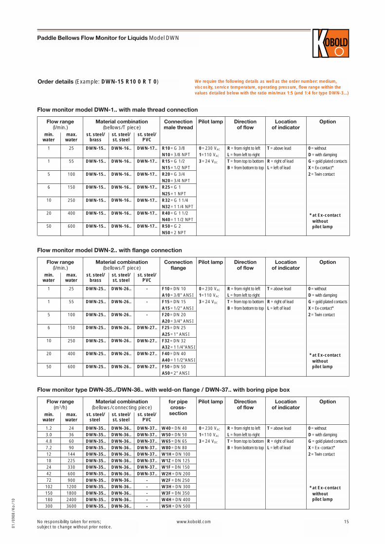
Order details (Example: DWN-15 R10 0 R T 0) We require the following details as well as the order number: medium,viscosity, service temperature, operating pressure, flow range within thevalues detailed below with the ratio min/max 1:5 (and 1:4 for type DWN-3...)
min.water
25 DWN-15.. DWN-16.. DWN-17..
max.water
1
st. steel/brass
55 DWN-15.. DWN-16.. DWN-17..1
100 DWN-15.. DWN-16.. DWN-17..5
Material combination(bellows/T piece)
L= from left to right
T= from top to bottom
B= from bottom to top
Flow range(l/min.)
150 DWN-15.. DWN-16.. DWN-17..6
st. steel/st. steel
st. steel/PVC
Option
D=with damping
G=gold plated contacts
X=Ex-contact*
2=Twin contact
Pilot lamp Direction of flow
R= from right to left 0=withoutR10=G 3/8N10=3/8 NPTR15=G 1/2N15=1/2 NPTR20=G 3/4N20=3/4 NPTR25=G 1
Connectionmale thread
250 DWN-15.. DWN-16.. DWN-17..10
400 DWN-15.. DWN-16.. DWN-17..20
600 DWN-15.. DWN-16.. DWN-17..50
N25=1 NPTR32=G 1 1/4N32=1 1/4 NPTR40=G 1 1/2N40=1 1/2 NPTR50=G 2N50=2 NPT
Flow monitor model DWN-1.. with male thread connection
0=230 VAC
1=110 VAC
3=24 VDC R= right of lead
L=left of lead
T=above lead
Location of indicator
min.water
25 DWN-25.. DWN-26.. -
max.water
1
st. steel/brass
55 DWN-25.. DWN-26.. -1
100 DWN-25.. DWN-26.. -5
Material combination(bellows/T piece)
L= from left to right
T= from top to bottom
B= from bottom to top
Flow range(l/min.)
150 DWN-25.. DWN-26.. DWN-27..6
st. steel/st. steel
st. steel/PVC
Option
D=with damping
G=gold plated contacts
X=Ex-contact*
2=Twin contact
Pilot lamp Direction of flow
R= from right to left 0=withoutF10=DN 10A10=3/8" ANSIF15=DN 15A15=1/2" ANSIF20=DN 20A20=3/4" ANSIF25=DN 25
Connectionflange
250 DWN-25.. DWN-26.. DWN-27..10
400 DWN-25.. DWN-26.. DWN-27..20
600 DWN-25.. DWN-26.. DWN-27..50
A25=1" ANSIF32=DN 32A32=11/4"ANSIF40=DN 40A40=11/2"ANSIF50=DN 50A50=2" ANSI
Flow monitor model DWN-2.. with flange connection
0=230 VAC
1=110 VAC
3=24 VDC R= right of lead
L=left of lead
T=above lead
Location of indicator
min.water
24 DWN-35.. DWN-36.. DWN-37..
max.water
1.2
st. steel/steel
36 DWN-35.. DWN-36.. DWN-37..3.060 DWN-35.. DWN-36.. DWN-37..4.890 DWN-35.. DWN-36.. DWN-37..7.2144 DWN-35.. DWN-36.. DWN-37..12225 DWN-35.. DWN-36.. DWN-37..18
Material combination(bellows/connecting piece)
L= from left to right
T= from top to bottom
B= from bottom to top
Flow range(m3/h)
330 DWN-35.. DWN-36.. DWN-37..24
st. steel/st. steel
st. steel/PVC
Option
D=with damping
G=gold plated contacts
X=Ex-contact*
2=Twin contact
Pilot lamp Direction of flow
R= from right to left 0=withoutW40=DN 40W50=DN 50W65=DN 65W80=DN 80W1H=DN 100W1Z=DN 125W1F=DN 150
for pipecross-section
600 DWN-35.. DWN-36.. DWN-37..42900 DWN-35.. DWN-36.. -721200 DWN-35.. DWN-36.. -1021800 DWN-35.. DWN-36.. -1502400 DWN-35.. DWN-36.. -1803600 DWN-35.. DWN-36.. -300
W2H=DN 200W2F=DN 250W3H=DN 300W3F=DN 350W4H=DN 400W5H=DN 500
Flow monitor type DWN-35../DWN-36.. with weld-on flange / DWN-37.. with boring pipe box
0=230 VAC
1=110 VAC
3=24 VDC R= right of lead
L=left of lead
T=above lead
Location of indicator
01 /
0908
/ K
o / 1
0
* at Ex-contact without pilot lamp
* at Ex-contact without pilot lamp
* at Ex-contact without pilot lamp
16 No responsibility taken for errors; subject to change without prior notice.
Paddle Bellows Flow Monitor for Liquids Model DWN
www.kobold.com
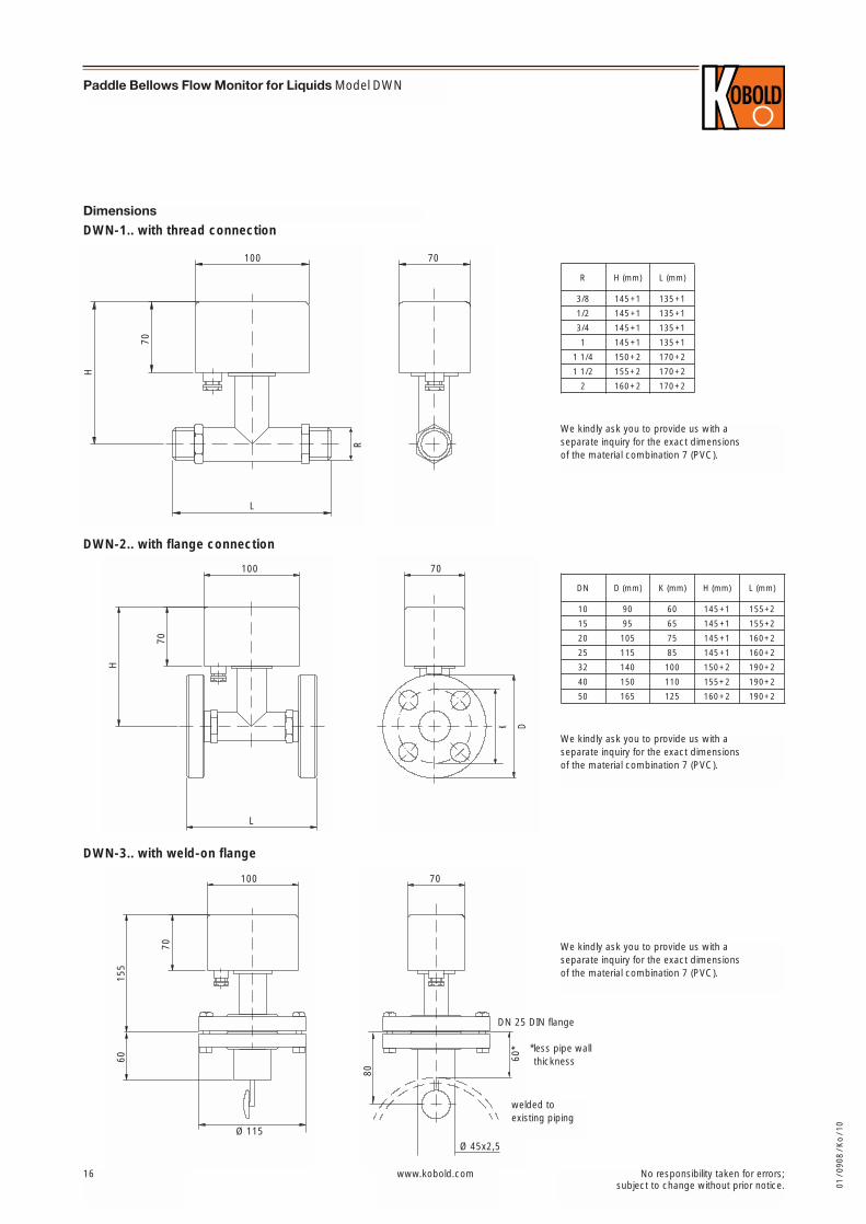
DimensionsDWN-1.. with thread connection
DWN-2.. with flange connection
DWN-3.. with weld-on flange
70
70
DK
70
Ø 45x2,5
60*
80
100
L
H
70
R
L
100
H
70
100
Ø 115
70
155
60
welded toexisting piping
H (mm) L (mm)
145+1 135+1
145+1 135+1
135+1145+1
R
3/8
1/2
3/4
145+1 135+1
150+2 170+2
155+2 170+2
1
1 1/4
1 1/2
160+2 170+22
D (mm) K (mm) H (mm)
90 60 145+1
95 65 145+1
75 145+1105
DN
10
15
20
115 85 145+1
140 100 150+2
150 110 155+2
25
32
40
165 125 160+250
L (mm)
155+2
155+2
160+2
160+2
190+2
190+2
190+2
We kindly ask you to provide us with a separate inquiry for the exact dimensions of the material combination 7 (PVC).
We kindly ask you to provide us with a separate inquiry for the exact dimensions of the material combination 7 (PVC).
We kindly ask you to provide us with a separate inquiry for the exact dimensions of the material combination 7 (PVC).
*less pipe wall
DN 25 DIN flange
thickness
01 /
0908
/ K
o / 1
0