Embed Size (px)
Citation preview

HOME
è SHOW MORE
EVERYTHING UNDER CONTROL.
THE NEW PALCOM P7
KNUCKLE BOOM CRANESPK 34002 SH
MORE COMFORT IN ROPE WINCH OPERATION
The SRC (Syncronised Rope Control) system maintains a constant distance between the pully head and the hook block. This advantage is particularly valuable in terms of use for the operator, and it also noticeably improves the efficiency of any operation.

HOME
OVERVIEW
FEATURES
ABOUT US
è SHOW MORE
EVERYTHING UNDER CONTROL.
THE NEW PALCOM P7
KNUCKLE BOOM CRANESPK 34002 SH
VIDEO
MORE COMFORT IN ROPE WINCH OPERATION
The SRC (Syncronised Rope Control) system maintains a constant distance between the pully head and the hook block. This advantage is particularly valuable in terms of use for the operator, and it also noticeably improves the efficiency of any operation.
EVERYTHING UNDER CONTROL.THE NEW PALCOM P7
WWW.PALFINGER.COM
LIFETIME EXCELLENCE
When PALFINGER combines its customers’ demands and all of the company’s expertise into a single product, the outcome can only be revolutionary: The new PALCOM P7, PALFINGER’s first in-house development in the field of loader crane remote controls. Ergonomically designed and packed to the hilt with innovative control functions and safety features. This remote control system enables effortless, safe and easy operation.
PALF
ING
ER A
G ·
5020
Sal
zbur
g, A
ustr
ia ·
E-M
ail i
nfo@
palfi
nger
.com

OVERVIEW
KNUCKLE BOOM CRANESPK 34002 SH
GENERAL TECHNICAL DATA APPLICATION
FUNCTIONAL DESIGN AND THE LATEST CONTROL TECHNOLOGY SET STANDARDS IN OPERATOR FRIEDLINESS AND COMFORT
èMore lifting power due to S-HPLS è Additional applications due to Power Link PLus è More efficient and faster through continuous slewing systemè Increased operating times due to low maintanence extension systemè Higher payloads due to intelligent leightweight design
(100.39")
(45.67")
(39.76"–45.67")
(39.37")
(84.06")
(28.
23")
(91.
73")
(104
.33"
) (174
.65"
)
(220.47"–291.34")
2135
1000
1010–1160
1160
2550
5600–7400
717
2330
2650
4436
(100.39")
(45.67")
(39.76"–45.67")
(39.37")
(84.06")
(28.
23")
(91.
73")
(104
.33"
) (174
.65"
)
(220.47"–291.34")
2135
1000
1010–1160
1160
2550
5600–7400
717
2330
2650
4436
(100.39")
(45.67")
(39.76"–45.67")
(39.37")
(84.06")
(28.
23")
(91.
73")
(104
.33"
) (174
.65"
)
(220.47"–291.34")
2135
1000
1010–1160
1160
2550
5600–7400
717
2330
2650
4436
KNUCKLE BOOM CRANESPK 34002 SH
GENERAL TECHNICAL DATA APPLICATION
OVERVIEW
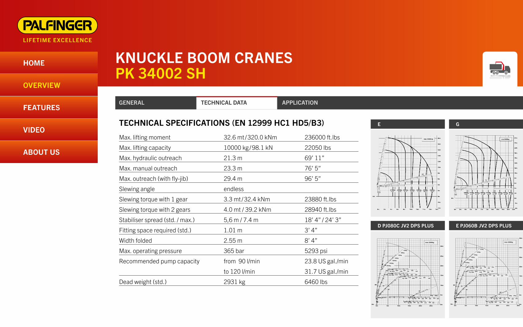
Max. lifting moment 32.6 mt / 320.0 kNm 236000 ft.lbs
Max. lifting capacity 10000 kg / 98.1 kN 22050 lbs
Max. hydraulic outreach 21.3 m 69’ 11”
Max. manual outreach 23.3 m 76’ 5”
Max. outreach (with fly-jib) 29.4 m 96’ 5”
Slewing angle endless
Slewing torque with 1 gear 3.3 mt / 32.4 kNm 23880 ft.lbs
Slewing torque with 2 gears 4.0 mt / 39.2 kNm 28940 ft.lbs
Stabiliser spread (std. / max.) 5,6 m / 7.4 m 18’ 4” / 24’ 3”
Fitting space required (std.) 1.01 m 3’ 4”
Width folded 2.55 m 8’ 4”
Max. operating pressure 365 bar 5293 psi
Recommended pump capacity from 90 l/min 23.8 US gal./min
to 120 l/min 31.7 US gal./min
Dead weight (std.) 2931 kg 6460 lbs
TECHNICAL SPECIFICATIONS (EN 12999 HC1 HD5/B3) E
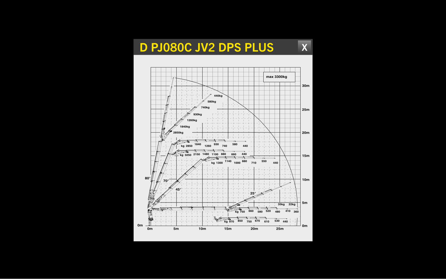
D PJ080C JV2 DPS PLUS
G
E PJ060B JV2 DPS PLUS
Sous reserve de modifications de conception. Les tolerances relatives a la technique de production doivent etre prises en consideration. Subject to change, production tolerances have to be taken into account. Konstruktionsänderungen vorbehalten, fertigungstechn. Toleranzen müssen berücksichtigt werden.
Charges autorisées pour le treuil, voir DTKBW0000–04.0100For Rope winch load capacity refer to page DTKBW0000–04.0100Zulässige Traglasten für Seilwinde siehe Datenblatt DTKBW0000–04.0100
Représentation symbolique de la grue, indication avec angle de premier bras 20° et extensions an position horizontaleSymbolic crane figure, indications at 20° main boom position & load arm in horizontal positionKrandarstellung symbolisch, Angaben bei 20° Hauptarmstellung & Lastarm horizontal
Classement: HC1 HD5/B3 en mesure EN12999 Classification: HC1 HD5/B3 in EN12999 Einstufung: HC1 HD5/B3 nach EN12999
Dual Power System
plusDPS
max 3300kg
22kg35kg
kg
kg
kg
kg
kg
930
1100
580
660
880 550
520
670
410
530
2850
3250
1300
750
970
440
440
740
880
440710
360
440
480
610
930kg
740kg
440kg
580kg
1260kg
1840kg
2850kg
1840
2150
1140
660
850
1260
1480
1000
580
750
80°
25°45°
70°
0m0m
30m
25m
20m
15m
10m
5m
0m 5m 15m 20m 25m10m
Les charges admissibles du diagramme ci–apres se reduisent du poids de la rallonge manuelle utilisee. When using mechanical boom extensions, the loads, shown on the charts need to be reduced by the weight of these extensions. Die Tragkräfte laut Diagramm verringern sich bei Verwendung von mechanischen Verlängerungen um deren Eigengewicht.
Diagramme de capacitLifting capacity diagram Traglastdiagramm
DTS407SHD/04
1600
05/2010PK 34002–SH D PJ 080 C JV2 DPS+
PK 34002–SHTypeModelModell
PagePageSeite
ChapitreChapterKapitel
EditionEditionAusgabe
(S407–SK–D)
Charges autorisées pour le treuil, voir DTKBW0000–04.0100For Rope winch load capacity refer to page DTKBW0000–04.0100Zulässige Traglasten für Seilwinde siehe Datenblatt DTKBW0000–04.0100
Représentation symbolique de la grue, indication avec angle de premier bras 20° et extensions an position horizontaleSymbolic crane figure, indications at 20° main boom position & load arm in horizontal positionKrandarstellung symbolisch, Angaben bei 20° Hauptarmstellung & Lastarm horizontal
Classement: HC1 HD5/B3 en mesure EN12999 Classification: HC1 HD5/B3 in EN12999 Einstufung: HC1 HD5/B3 nach EN12999
Sous reserve de modifications de conception. Les tolerances relatives a la technique de production doivent etre prises en consideration. Subject to change, production tolerances have to be taken into account. Konstruktionsänderungen vorbehalten, fertigungstechn. Toleranzen müssen berücksichtigt werden.
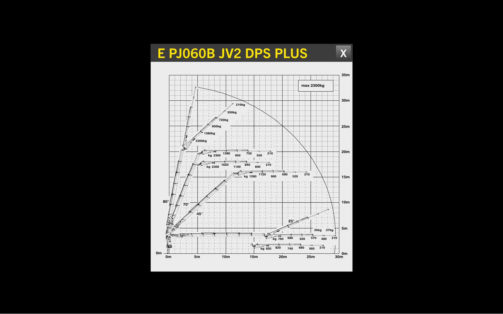
Dual Power System
plusDPS
max 2300kg
Les charges admissibles du diagramme ci–apres se reduisent du poids de la rallonge manuelle utilisee. When using mechanical boom extensions, the loads, shown on the charts need to be reduced by the weight of these extensions. Die Tragkräfte laut Diagramm verringern sich bei Verwendung von mechanischen Verlängerungen um deren Eigengewicht.
27kg35kg
kg
kg
kg
kg
kg
210
210
720
840
210690
210
210
680
570
2300
2300
1280
920
760
550
600
520
560
480
720kg
210kg
550kg
950kg
1380kg
2300kg
1380
1620
1120
820
680
950
1100
900
740
620
80°
25°
45°
70°
0m0m
30m
35m
25m
20m
15m
10m
5m
0m 5m 15m 20m 25m 30m10m
Diagramme de capacitLifting capacity diagram Traglastdiagramm
DTS407SHD/04
2000
05/2010PK 34002–SH E PJ 060 B JV2 DPS+
PK 34002–SHTypeModelModell
PagePageSeite
ChapitreChapterKapitel
EditionEditionAusgabe
(S407–SK–D)
KNUCKLE BOOM CRANESPK 34002 SH
GENERAL TECHNICAL DATA APPLICATION
HOME
OVERVIEW
Max. lifting moment 32.6 mt / 320.0 kNm 236000 ft.lbs
Max. lifting capacity 10000 kg / 98.1 kN 22050 lbs
Max. hydraulic outreach 21.3 m 69’ 11”
Max. manual outreach 23.3 m 76’ 5”
Max. outreach (with fly-jib) 29.4 m 96’ 5”
Slewing angle endless
Slewing torque with 1 gear 3.3 mt / 32.4 kNm 23880 ft.lbs
Slewing torque with 2 gears 4.0 mt / 39.2 kNm 28940 ft.lbs
Stabiliser spread (std. / max.) 5,6 m / 7.4 m 18’ 4” / 24’ 3”
Fitting space required (std.) 1.01 m 3’ 4”
Width folded 2.55 m 8’ 4”
Max. operating pressure 365 bar 5293 psi
Recommended pump capacity from 90 l/min 23.8 US gal./min
to 120 l/min 31.7 US gal./min
Dead weight (std.) 2931 kg 6460 lbs
TECHNICAL SPECIFICATIONS (EN 12999 HC1 HD5/B3)
FEATURES
ABOUT US
VIDEOE G
15°
max 10000kg
16.7m14.5m12.4m10.3m8.2m6.3m4.4m1420kg1640kg1960kg2450kg3250kg4450kg6700kg
0m0m
2m
4m
6m
8m
10m
12m
14m
16m
18m
20m
0m
–2m
–4m0m 2m 4m 6m 8m 10m 12m 14m 16m 18m
(S407–SK–D)
DTS407SHD/04
0500
05/2010PK 34002–SH E
PK 34002–SHTypeModelModell PagePageSeite
ChapitreChapterKapitel
EditionEditionAusgabe
0m 2m 4m 6m 8m 10m 12m 14m 16m 18m 20m 22m
15°
(S407–SK–D)
max 9300kg
4.6m 6.5m 8.4m 10.5m 12.6m 14.7m 16.8m 21.1m19.0m1040kg 930kg1200kg1420kg1740kg2250kg3000kg4150kg6300kg
–4m
–2m
0m0m
24m
22m
20m
18m
16m
14m
12m
10m
8m
6m
4m
2m
0m
DTS407SHD/04
0700
05/2010PK 34002–SH G
PK 34002–SHTypeModelModell PagePageSeite
ChapitreChapterKapitel
EditionEditionAusgabe
D PJ080C JV2 DPS PLUS E PJ060B JV2 DPS PLUS
Sous reserve de modifications de conception. Les tolerances relatives a la technique de production doivent etre prises en consideration. Subject to change, production tolerances have to be taken into account. Konstruktionsänderungen vorbehalten, fertigungstechn. Toleranzen müssen berücksichtigt werden.
Charges autorisées pour le treuil, voir DTKBW0000–04.0100For Rope winch load capacity refer to page DTKBW0000–04.0100Zulässige Traglasten für Seilwinde siehe Datenblatt DTKBW0000–04.0100
Représentation symbolique de la grue, indication avec angle de premier bras 20° et extensions an position horizontaleSymbolic crane figure, indications at 20° main boom position & load arm in horizontal positionKrandarstellung symbolisch, Angaben bei 20° Hauptarmstellung & Lastarm horizontal
Classement: HC1 HD5/B3 en mesure EN12999 Classification: HC1 HD5/B3 in EN12999 Einstufung: HC1 HD5/B3 nach EN12999
Dual Power System
plusDPS
max 3300kg
22kg35kg
kg
kg
kg
kg
kg
930
1100
580
660
880 550
520
670
410
530
2850
3250
1300
750
970
440
440
740
880
440710
360
440
480
610
930kg
740kg
440kg
580kg
1260kg
1840kg
2850kg
1840
2150
1140
660
850
1260
1480
1000
580
750
80°
25°45°
70°
0m0m
30m
25m
20m
15m
10m
5m
0m 5m 15m 20m 25m10m
Les charges admissibles du diagramme ci–apres se reduisent du poids de la rallonge manuelle utilisee. When using mechanical boom extensions, the loads, shown on the charts need to be reduced by the weight of these extensions. Die Tragkräfte laut Diagramm verringern sich bei Verwendung von mechanischen Verlängerungen um deren Eigengewicht.
Diagramme de capacitLifting capacity diagram Traglastdiagramm
DTS407SHD/04
1600
05/2010PK 34002–SH D PJ 080 C JV2 DPS+
PK 34002–SHTypeModelModell
PagePageSeite
ChapitreChapterKapitel
EditionEditionAusgabe
(S407–SK–D)
Charges autorisées pour le treuil, voir DTKBW0000–04.0100For Rope winch load capacity refer to page DTKBW0000–04.0100Zulässige Traglasten für Seilwinde siehe Datenblatt DTKBW0000–04.0100
Représentation symbolique de la grue, indication avec angle de premier bras 20° et extensions an position horizontaleSymbolic crane figure, indications at 20° main boom position & load arm in horizontal positionKrandarstellung symbolisch, Angaben bei 20° Hauptarmstellung & Lastarm horizontal
Classement: HC1 HD5/B3 en mesure EN12999 Classification: HC1 HD5/B3 in EN12999 Einstufung: HC1 HD5/B3 nach EN12999
Sous reserve de modifications de conception. Les tolerances relatives a la technique de production doivent etre prises en consideration. Subject to change, production tolerances have to be taken into account. Konstruktionsänderungen vorbehalten, fertigungstechn. Toleranzen müssen berücksichtigt werden.
Dual Power System
plusDPS
max 2300kg
Les charges admissibles du diagramme ci–apres se reduisent du poids de la rallonge manuelle utilisee. When using mechanical boom extensions, the loads, shown on the charts need to be reduced by the weight of these extensions. Die Tragkräfte laut Diagramm verringern sich bei Verwendung von mechanischen Verlängerungen um deren Eigengewicht.
27kg35kg
kg
kg
kg
kg
kg
210
210
720
840
210690
210
210
680
570
2300
2300
1280
920
760
550
600
520
560
480
720kg
210kg
550kg
950kg
1380kg
2300kg
1380
1620
1120
820
680
950
1100
900
740
620
80°
25°
45°
70°
0m0m
30m
35m
25m
20m
15m
10m
5m
0m 5m 15m 20m 25m 30m10m
Diagramme de capacitLifting capacity diagram Traglastdiagramm
DTS407SHD/04
2000
05/2010PK 34002–SH E PJ 060 B JV2 DPS+
PK 34002–SHTypeModelModell
PagePageSeite
ChapitreChapterKapitel
EditionEditionAusgabe
(S407–SK–D)
E
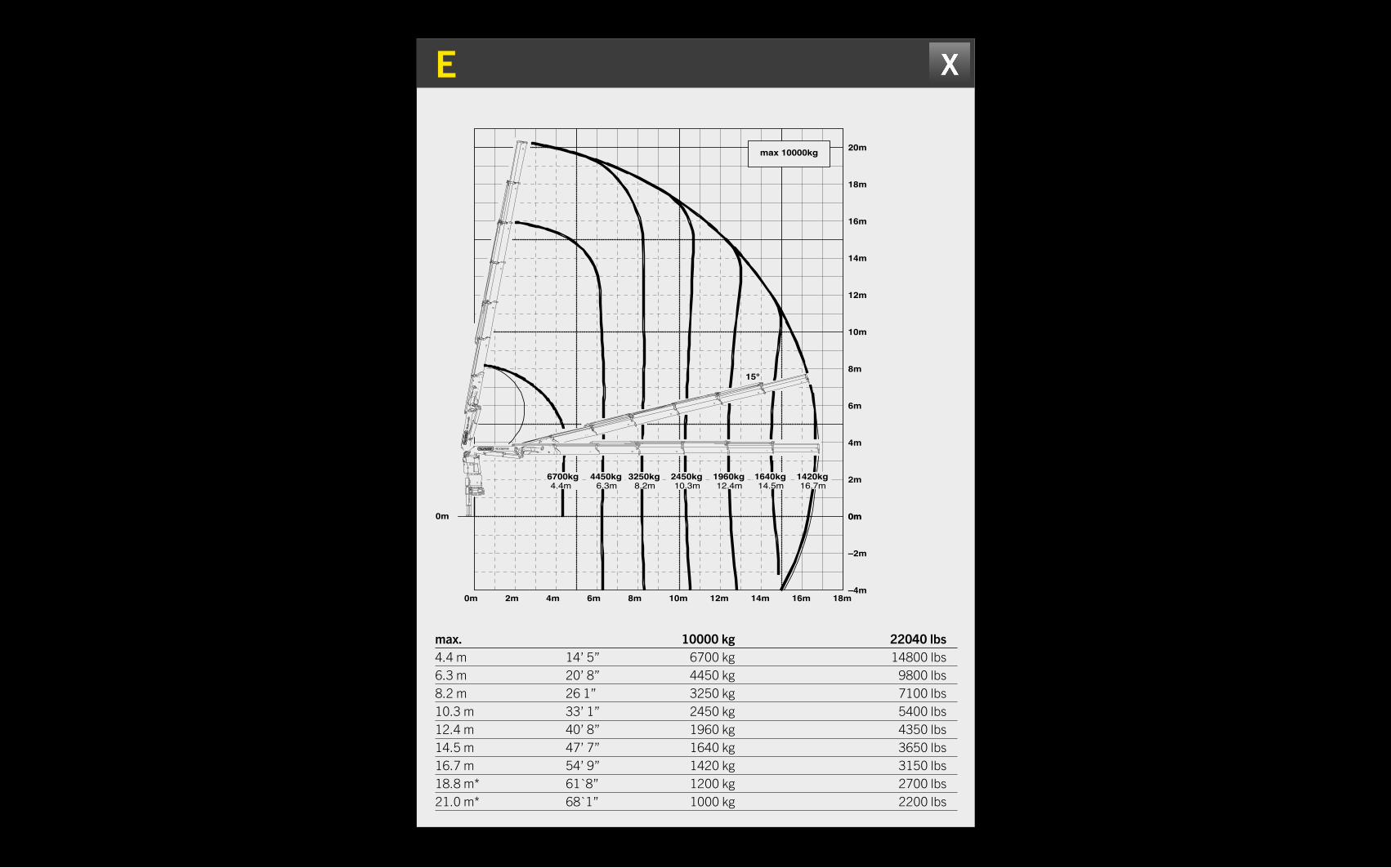
max. 10000 kg 22040 lbs4.4 m 14’ 5” 6700 kg 14800 lbs6.3 m 20’ 8” 4450 kg 9800 lbs8.2 m 26 1” 3250 kg 7100 lbs10.3 m 33’ 1” 2450 kg 5400 lbs12.4 m 40’ 8” 1960 kg 4350 lbs14.5 m 47’ 7” 1640 kg 3650 lbs16.7 m 54’ 9” 1420 kg 3150 lbs18.8 m* 61`8” 1200 kg 2700 lbs21.0 m* 68`1” 1000 kg 2200 lbs
15°
max 10000kg
16.7m14.5m12.4m10.3m8.2m6.3m4.4m1420kg1640kg1960kg2450kg3250kg4450kg6700kg
0m0m
2m
4m
6m
8m
10m
12m
14m
16m
18m
20m
0m
–2m
–4m0m 2m 4m 6m 8m 10m 12m 14m 16m 18m
(S407–SK–D)
DTS407SHD/04
0500
05/2010PK 34002–SH E
PK 34002–SHTypeModelModell PagePageSeite
ChapitreChapterKapitel
EditionEditionAusgabe
KNUCKLE BOOM CRANESPK 34002 SH
GENERAL TECHNICAL DATA APPLICATION
HOME
OVERVIEW
Max. lifting moment 32.6 mt / 320.0 kNm 236000 ft.lbs
Max. lifting capacity 10000 kg / 98.1 kN 22050 lbs
Max. hydraulic outreach 21.3 m 69’ 11”
Max. manual outreach 23.3 m 76’ 5”
Max. outreach (with fly-jib) 29.4 m 96’ 5”
Slewing angle endless
Slewing torque with 1 gear 3.3 mt / 32.4 kNm 23880 ft.lbs
Slewing torque with 2 gears 4.0 mt / 39.2 kNm 28940 ft.lbs
Stabiliser spread (std. / max.) 5,6 m / 7.4 m 18’ 4” / 24’ 3”
Fitting space required (std.) 1.01 m 3’ 4”
Width folded 2.55 m 8’ 4”
Max. operating pressure 365 bar 5293 psi
Recommended pump capacity from 90 l/min 23.8 US gal./min
to 120 l/min 31.7 US gal./min
Dead weight (std.) 2931 kg 6460 lbs
TECHNICAL SPECIFICATIONS (EN 12999 HC1 HD5/B3)
FEATURES
ABOUT US
VIDEOE G
15°
max 10000kg
16.7m14.5m12.4m10.3m8.2m6.3m4.4m1420kg1640kg1960kg2450kg3250kg4450kg6700kg
0m0m
2m
4m
6m
8m
10m
12m
14m
16m
18m
20m
0m
–2m
–4m0m 2m 4m 6m 8m 10m 12m 14m 16m 18m
(S407–SK–D)
DTS407SHD/04
0500
05/2010PK 34002–SH E
PK 34002–SHTypeModelModell PagePageSeite
ChapitreChapterKapitel
EditionEditionAusgabe
0m 2m 4m 6m 8m 10m 12m 14m 16m 18m 20m 22m
15°
(S407–SK–D)
max 9300kg
4.6m 6.5m 8.4m 10.5m 12.6m 14.7m 16.8m 21.1m19.0m1040kg 930kg1200kg1420kg1740kg2250kg3000kg4150kg6300kg
–4m
–2m
0m0m
24m
22m
20m
18m
16m
14m
12m
10m
8m
6m
4m
2m
0m
DTS407SHD/04
0700
05/2010PK 34002–SH G
PK 34002–SHTypeModelModell PagePageSeite
ChapitreChapterKapitel
EditionEditionAusgabe
D PJ080C JV2 DPS PLUS E PJ060B JV2 DPS PLUS
Sous reserve de modifications de conception. Les tolerances relatives a la technique de production doivent etre prises en consideration. Subject to change, production tolerances have to be taken into account. Konstruktionsänderungen vorbehalten, fertigungstechn. Toleranzen müssen berücksichtigt werden.
Charges autorisées pour le treuil, voir DTKBW0000–04.0100For Rope winch load capacity refer to page DTKBW0000–04.0100Zulässige Traglasten für Seilwinde siehe Datenblatt DTKBW0000–04.0100
Représentation symbolique de la grue, indication avec angle de premier bras 20° et extensions an position horizontaleSymbolic crane figure, indications at 20° main boom position & load arm in horizontal positionKrandarstellung symbolisch, Angaben bei 20° Hauptarmstellung & Lastarm horizontal
Classement: HC1 HD5/B3 en mesure EN12999 Classification: HC1 HD5/B3 in EN12999 Einstufung: HC1 HD5/B3 nach EN12999
Dual Power System
plusDPS
max 3300kg
22kg35kg
kg
kg
kg
kg
kg
930
1100
580
660
880 550
520
670
410
530
2850
3250
1300
750
970
440
440
740
880
440710
360
440
480
610
930kg
740kg
440kg
580kg
1260kg
1840kg
2850kg
1840
2150
1140
660
850
1260
1480
1000
580
750
80°
25°45°
70°
0m0m
30m
25m
20m
15m
10m
5m
0m 5m 15m 20m 25m10m
Les charges admissibles du diagramme ci–apres se reduisent du poids de la rallonge manuelle utilisee. When using mechanical boom extensions, the loads, shown on the charts need to be reduced by the weight of these extensions. Die Tragkräfte laut Diagramm verringern sich bei Verwendung von mechanischen Verlängerungen um deren Eigengewicht.
Diagramme de capacitLifting capacity diagram Traglastdiagramm
DTS407SHD/04
1600
05/2010PK 34002–SH D PJ 080 C JV2 DPS+
PK 34002–SHTypeModelModell
PagePageSeite
ChapitreChapterKapitel
EditionEditionAusgabe
(S407–SK–D)
Charges autorisées pour le treuil, voir DTKBW0000–04.0100For Rope winch load capacity refer to page DTKBW0000–04.0100Zulässige Traglasten für Seilwinde siehe Datenblatt DTKBW0000–04.0100
Représentation symbolique de la grue, indication avec angle de premier bras 20° et extensions an position horizontaleSymbolic crane figure, indications at 20° main boom position & load arm in horizontal positionKrandarstellung symbolisch, Angaben bei 20° Hauptarmstellung & Lastarm horizontal
Classement: HC1 HD5/B3 en mesure EN12999 Classification: HC1 HD5/B3 in EN12999 Einstufung: HC1 HD5/B3 nach EN12999
Sous reserve de modifications de conception. Les tolerances relatives a la technique de production doivent etre prises en consideration. Subject to change, production tolerances have to be taken into account. Konstruktionsänderungen vorbehalten, fertigungstechn. Toleranzen müssen berücksichtigt werden.
Dual Power System
plusDPS
max 2300kg
Les charges admissibles du diagramme ci–apres se reduisent du poids de la rallonge manuelle utilisee. When using mechanical boom extensions, the loads, shown on the charts need to be reduced by the weight of these extensions. Die Tragkräfte laut Diagramm verringern sich bei Verwendung von mechanischen Verlängerungen um deren Eigengewicht.
27kg35kg
kg
kg
kg
kg
kg
210
210
720
840
210690
210
210
680
570
2300
2300
1280
920
760
550
600
520
560
480
720kg
210kg
550kg
950kg
1380kg
2300kg
1380
1620
1120
820
680
950
1100
900
740
620
80°
25°
45°
70°
0m0m
30m
35m
25m
20m
15m
10m
5m
0m 5m 15m 20m 25m 30m10m
Diagramme de capacitLifting capacity diagram Traglastdiagramm
DTS407SHD/04
2000
05/2010PK 34002–SH E PJ 060 B JV2 DPS+
PK 34002–SHTypeModelModell
PagePageSeite
ChapitreChapterKapitel
EditionEditionAusgabe
(S407–SK–D)
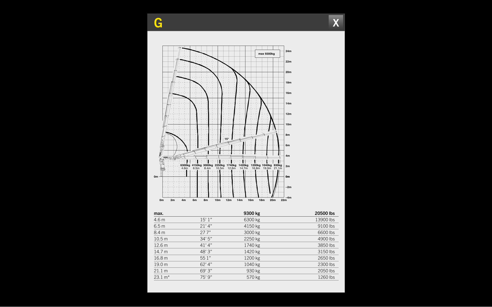
max. 9300 kg 20500 lbs4.6 m 15’ 1” 6300 kg 13900 lbs6.5 m 21’ 4” 4150 kg 9100 lbs8.4 m 27 7” 3000 kg 6600 lbs10.5 m 34’ 5” 2250 kg 4900 lbs12.6 m 41’ 4” 1740 kg 3850 lbs14.7 m 48’ 3” 1420 kg 3150 lbs16.8 m 55 1” 1200 kg 2650 lbs19.0 m 62’ 4” 1040 kg 2300 lbs21.1 m 69’ 3” 930 kg 2050 lbs23.1 m* 75’ 9” 570 kg 1260 lbs
G
0m 2m 4m 6m 8m 10m 12m 14m 16m 18m 20m 22m
15°
(S407–SK–D)
max 9300kg
4.6m 6.5m 8.4m 10.5m 12.6m 14.7m 16.8m 21.1m19.0m1040kg 930kg1200kg1420kg1740kg2250kg3000kg4150kg6300kg
–4m
–2m
0m0m
24m
22m
20m
18m
16m
14m
12m
10m
8m
6m
4m
2m
0m
DTS407SHD/04
0700
05/2010PK 34002–SH G
PK 34002–SHTypeModelModell PagePageSeite
ChapitreChapterKapitel
EditionEditionAusgabe
KNUCKLE BOOM CRANESPK 34002 SH
GENERAL TECHNICAL DATA APPLICATION
HOME
OVERVIEW
Max. lifting moment 32.6 mt / 320.0 kNm 236000 ft.lbs
Max. lifting capacity 10000 kg / 98.1 kN 22050 lbs
Max. hydraulic outreach 21.3 m 69’ 11”
Max. manual outreach 23.3 m 76’ 5”
Max. outreach (with fly-jib) 29.4 m 96’ 5”
Slewing angle endless
Slewing torque with 1 gear 3.3 mt / 32.4 kNm 23880 ft.lbs
Slewing torque with 2 gears 4.0 mt / 39.2 kNm 28940 ft.lbs
Stabiliser spread (std. / max.) 5,6 m / 7.4 m 18’ 4” / 24’ 3”
Fitting space required (std.) 1.01 m 3’ 4”
Width folded 2.55 m 8’ 4”
Max. operating pressure 365 bar 5293 psi
Recommended pump capacity from 90 l/min 23.8 US gal./min
to 120 l/min 31.7 US gal./min
Dead weight (std.) 2931 kg 6460 lbs
TECHNICAL SPECIFICATIONS (EN 12999 HC1 HD5/B3)
FEATURES
ABOUT US
VIDEOE G
15°
max 10000kg
16.7m14.5m12.4m10.3m8.2m6.3m4.4m1420kg1640kg1960kg2450kg3250kg4450kg6700kg
0m0m
2m
4m
6m
8m
10m
12m
14m
16m
18m
20m
0m
–2m
–4m0m 2m 4m 6m 8m 10m 12m 14m 16m 18m
(S407–SK–D)
DTS407SHD/04
0500
05/2010PK 34002–SH E
PK 34002–SHTypeModelModell PagePageSeite
ChapitreChapterKapitel
EditionEditionAusgabe
0m 2m 4m 6m 8m 10m 12m 14m 16m 18m 20m 22m
15°
(S407–SK–D)
max 9300kg
4.6m 6.5m 8.4m 10.5m 12.6m 14.7m 16.8m 21.1m19.0m1040kg 930kg1200kg1420kg1740kg2250kg3000kg4150kg6300kg
–4m
–2m
0m0m
24m
22m
20m
18m
16m
14m
12m
10m
8m
6m
4m
2m
0m
DTS407SHD/04
0700
05/2010PK 34002–SH G
PK 34002–SHTypeModelModell PagePageSeite
ChapitreChapterKapitel
EditionEditionAusgabe
D PJ080C JV2 DPS PLUS E PJ060B JV2 DPS PLUS
Sous reserve de modifications de conception. Les tolerances relatives a la technique de production doivent etre prises en consideration. Subject to change, production tolerances have to be taken into account. Konstruktionsänderungen vorbehalten, fertigungstechn. Toleranzen müssen berücksichtigt werden.
Charges autorisées pour le treuil, voir DTKBW0000–04.0100For Rope winch load capacity refer to page DTKBW0000–04.0100Zulässige Traglasten für Seilwinde siehe Datenblatt DTKBW0000–04.0100
Représentation symbolique de la grue, indication avec angle de premier bras 20° et extensions an position horizontaleSymbolic crane figure, indications at 20° main boom position & load arm in horizontal positionKrandarstellung symbolisch, Angaben bei 20° Hauptarmstellung & Lastarm horizontal
Classement: HC1 HD5/B3 en mesure EN12999 Classification: HC1 HD5/B3 in EN12999 Einstufung: HC1 HD5/B3 nach EN12999
Dual Power System
plusDPS
max 3300kg
22kg35kg
kg
kg
kg
kg
kg
930
1100
580
660
880 550
520
670
410
530
2850
3250
1300
750
970
440
440
740
880
440710
360
440
480
610
930kg
740kg
440kg
580kg
1260kg
1840kg
2850kg
1840
2150
1140
660
850
1260
1480
1000
580
750
80°
25°45°
70°
0m0m
30m
25m
20m
15m
10m
5m
0m 5m 15m 20m 25m10m
Les charges admissibles du diagramme ci–apres se reduisent du poids de la rallonge manuelle utilisee. When using mechanical boom extensions, the loads, shown on the charts need to be reduced by the weight of these extensions. Die Tragkräfte laut Diagramm verringern sich bei Verwendung von mechanischen Verlängerungen um deren Eigengewicht.
Diagramme de capacitLifting capacity diagram Traglastdiagramm
DTS407SHD/04
1600
05/2010PK 34002–SH D PJ 080 C JV2 DPS+
PK 34002–SHTypeModelModell
PagePageSeite
ChapitreChapterKapitel
EditionEditionAusgabe
(S407–SK–D)
Charges autorisées pour le treuil, voir DTKBW0000–04.0100For Rope winch load capacity refer to page DTKBW0000–04.0100Zulässige Traglasten für Seilwinde siehe Datenblatt DTKBW0000–04.0100
Représentation symbolique de la grue, indication avec angle de premier bras 20° et extensions an position horizontaleSymbolic crane figure, indications at 20° main boom position & load arm in horizontal positionKrandarstellung symbolisch, Angaben bei 20° Hauptarmstellung & Lastarm horizontal
Classement: HC1 HD5/B3 en mesure EN12999 Classification: HC1 HD5/B3 in EN12999 Einstufung: HC1 HD5/B3 nach EN12999
Sous reserve de modifications de conception. Les tolerances relatives a la technique de production doivent etre prises en consideration. Subject to change, production tolerances have to be taken into account. Konstruktionsänderungen vorbehalten, fertigungstechn. Toleranzen müssen berücksichtigt werden.
Dual Power System
plusDPS
max 2300kg
Les charges admissibles du diagramme ci–apres se reduisent du poids de la rallonge manuelle utilisee. When using mechanical boom extensions, the loads, shown on the charts need to be reduced by the weight of these extensions. Die Tragkräfte laut Diagramm verringern sich bei Verwendung von mechanischen Verlängerungen um deren Eigengewicht.
27kg35kg
kg
kg
kg
kg
kg
210
210
720
840
210690
210
210
680
570
2300
2300
1280
920
760
550
600
520
560
480
720kg
210kg
550kg
950kg
1380kg
2300kg
1380
1620
1120
820
680
950
1100
900
740
620
80°
25°
45°
70°
0m0m
30m
35m
25m
20m
15m
10m
5m
0m 5m 15m 20m 25m 30m10m
Diagramme de capacitLifting capacity diagram Traglastdiagramm
DTS407SHD/04
2000
05/2010PK 34002–SH E PJ 060 B JV2 DPS+
PK 34002–SHTypeModelModell
PagePageSeite
ChapitreChapterKapitel
EditionEditionAusgabe
(S407–SK–D)
D PJ080C JV2 DPS PLUS
Sous reserve de modifications de conception. Les tolerances relatives a la technique de production doivent etre prises en consideration. Subject to change, production tolerances have to be taken into account. Konstruktionsänderungen vorbehalten, fertigungstechn. Toleranzen müssen berücksichtigt werden.
Charges autorisées pour le treuil, voir DTKBW0000–04.0100For Rope winch load capacity refer to page DTKBW0000–04.0100Zulässige Traglasten für Seilwinde siehe Datenblatt DTKBW0000–04.0100
Représentation symbolique de la grue, indication avec angle de premier bras 20° et extensions an position horizontaleSymbolic crane figure, indications at 20° main boom position & load arm in horizontal positionKrandarstellung symbolisch, Angaben bei 20° Hauptarmstellung & Lastarm horizontal
Classement: HC1 HD5/B3 en mesure EN12999 Classification: HC1 HD5/B3 in EN12999 Einstufung: HC1 HD5/B3 nach EN12999
Dual Power System
plusDPS
max 3300kg
22kg35kg
kg
kg
kg
kg
kg
930
1100
580
660
880 550
520
670
410
530
2850
3250
1300
750
970
440
440
740
880
440710
360
440
480
610
930kg
740kg
440kg
580kg
1260kg
1840kg
2850kg
1840
2150
1140
660
850
1260
1480
1000
580
750
80°
25°45°
70°
0m0m
30m
25m
20m
15m
10m
5m
0m 5m 15m 20m 25m10m
Les charges admissibles du diagramme ci–apres se reduisent du poids de la rallonge manuelle utilisee. When using mechanical boom extensions, the loads, shown on the charts need to be reduced by the weight of these extensions. Die Tragkräfte laut Diagramm verringern sich bei Verwendung von mechanischen Verlängerungen um deren Eigengewicht.
Diagramme de capacitLifting capacity diagram Traglastdiagramm
DTS407SHD/04
1600
05/2010PK 34002–SH D PJ 080 C JV2 DPS+
PK 34002–SHTypeModelModell
PagePageSeite
ChapitreChapterKapitel
EditionEditionAusgabe
(S407–SK–D)
KNUCKLE BOOM CRANESPK 34002 SH
GENERAL TECHNICAL DATA APPLICATION
HOME
OVERVIEW
Max. lifting moment 32.6 mt / 320.0 kNm 236000 ft.lbs
Max. lifting capacity 10000 kg / 98.1 kN 22050 lbs
Max. hydraulic outreach 21.3 m 69’ 11”
Max. manual outreach 23.3 m 76’ 5”
Max. outreach (with fly-jib) 29.4 m 96’ 5”
Slewing angle endless
Slewing torque with 1 gear 3.3 mt / 32.4 kNm 23880 ft.lbs
Slewing torque with 2 gears 4.0 mt / 39.2 kNm 28940 ft.lbs
Stabiliser spread (std. / max.) 5,6 m / 7.4 m 18’ 4” / 24’ 3”
Fitting space required (std.) 1.01 m 3’ 4”
Width folded 2.55 m 8’ 4”
Max. operating pressure 365 bar 5293 psi
Recommended pump capacity from 90 l/min 23.8 US gal./min
to 120 l/min 31.7 US gal./min
Dead weight (std.) 2931 kg 6460 lbs
TECHNICAL SPECIFICATIONS (EN 12999 HC1 HD5/B3)
FEATURES
ABOUT US
VIDEOE G
15°
max 10000kg
16.7m14.5m12.4m10.3m8.2m6.3m4.4m1420kg1640kg1960kg2450kg3250kg4450kg6700kg
0m0m
2m
4m
6m
8m
10m
12m
14m
16m
18m
20m
0m
–2m
–4m0m 2m 4m 6m 8m 10m 12m 14m 16m 18m
(S407–SK–D)
DTS407SHD/04
0500
05/2010PK 34002–SH E
PK 34002–SHTypeModelModell PagePageSeite
ChapitreChapterKapitel
EditionEditionAusgabe
0m 2m 4m 6m 8m 10m 12m 14m 16m 18m 20m 22m
15°
(S407–SK–D)
max 9300kg
4.6m 6.5m 8.4m 10.5m 12.6m 14.7m 16.8m 21.1m19.0m1040kg 930kg1200kg1420kg1740kg2250kg3000kg4150kg6300kg
–4m
–2m
0m0m
24m
22m
20m
18m
16m
14m
12m
10m
8m
6m
4m
2m
0m
DTS407SHD/04
0700
05/2010PK 34002–SH G
PK 34002–SHTypeModelModell PagePageSeite
ChapitreChapterKapitel
EditionEditionAusgabe
D PJ080C JV2 DPS PLUS E PJ060B JV2 DPS PLUS
Sous reserve de modifications de conception. Les tolerances relatives a la technique de production doivent etre prises en consideration. Subject to change, production tolerances have to be taken into account. Konstruktionsänderungen vorbehalten, fertigungstechn. Toleranzen müssen berücksichtigt werden.
Charges autorisées pour le treuil, voir DTKBW0000–04.0100For Rope winch load capacity refer to page DTKBW0000–04.0100Zulässige Traglasten für Seilwinde siehe Datenblatt DTKBW0000–04.0100
Représentation symbolique de la grue, indication avec angle de premier bras 20° et extensions an position horizontaleSymbolic crane figure, indications at 20° main boom position & load arm in horizontal positionKrandarstellung symbolisch, Angaben bei 20° Hauptarmstellung & Lastarm horizontal
Classement: HC1 HD5/B3 en mesure EN12999 Classification: HC1 HD5/B3 in EN12999 Einstufung: HC1 HD5/B3 nach EN12999
Dual Power System
plusDPS
max 3300kg
22kg35kg
kg
kg
kg
kg
kg
930
1100
580
660
880 550
520
670
410
530
2850
3250
1300
750
970
440
440
740
880
440710
360
440
480
610
930kg
740kg
440kg
580kg
1260kg
1840kg
2850kg
1840
2150
1140
660
850
1260
1480
1000
580
750
80°
25°45°
70°
0m0m
30m
25m
20m
15m
10m
5m
0m 5m 15m 20m 25m10m
Les charges admissibles du diagramme ci–apres se reduisent du poids de la rallonge manuelle utilisee. When using mechanical boom extensions, the loads, shown on the charts need to be reduced by the weight of these extensions. Die Tragkräfte laut Diagramm verringern sich bei Verwendung von mechanischen Verlängerungen um deren Eigengewicht.
Diagramme de capacitLifting capacity diagram Traglastdiagramm
DTS407SHD/04
1600
05/2010PK 34002–SH D PJ 080 C JV2 DPS+
PK 34002–SHTypeModelModell
PagePageSeite
ChapitreChapterKapitel
EditionEditionAusgabe
(S407–SK–D)
Charges autorisées pour le treuil, voir DTKBW0000–04.0100For Rope winch load capacity refer to page DTKBW0000–04.0100Zulässige Traglasten für Seilwinde siehe Datenblatt DTKBW0000–04.0100
Représentation symbolique de la grue, indication avec angle de premier bras 20° et extensions an position horizontaleSymbolic crane figure, indications at 20° main boom position & load arm in horizontal positionKrandarstellung symbolisch, Angaben bei 20° Hauptarmstellung & Lastarm horizontal
Classement: HC1 HD5/B3 en mesure EN12999 Classification: HC1 HD5/B3 in EN12999 Einstufung: HC1 HD5/B3 nach EN12999
Sous reserve de modifications de conception. Les tolerances relatives a la technique de production doivent etre prises en consideration. Subject to change, production tolerances have to be taken into account. Konstruktionsänderungen vorbehalten, fertigungstechn. Toleranzen müssen berücksichtigt werden.
Dual Power System
plusDPS
max 2300kg
Les charges admissibles du diagramme ci–apres se reduisent du poids de la rallonge manuelle utilisee. When using mechanical boom extensions, the loads, shown on the charts need to be reduced by the weight of these extensions. Die Tragkräfte laut Diagramm verringern sich bei Verwendung von mechanischen Verlängerungen um deren Eigengewicht.
27kg35kg
kg
kg
kg
kg
kg
210
210
720
840
210690
210
210
680
570
2300
2300
1280
920
760
550
600
520
560
480
720kg
210kg
550kg
950kg
1380kg
2300kg
1380
1620
1120
820
680
950
1100
900
740
620
80°
25°
45°
70°
0m0m
30m
35m
25m
20m
15m
10m
5m
0m 5m 15m 20m 25m 30m10m
Diagramme de capacitLifting capacity diagram Traglastdiagramm
DTS407SHD/04
2000
05/2010PK 34002–SH E PJ 060 B JV2 DPS+
PK 34002–SHTypeModelModell
PagePageSeite
ChapitreChapterKapitel
EditionEditionAusgabe
(S407–SK–D)
E PJ060B JV2 DPS PLUS
Charges autorisées pour le treuil, voir DTKBW0000–04.0100For Rope winch load capacity refer to page DTKBW0000–04.0100Zulässige Traglasten für Seilwinde siehe Datenblatt DTKBW0000–04.0100
Représentation symbolique de la grue, indication avec angle de premier bras 20° et extensions an position horizontaleSymbolic crane figure, indications at 20° main boom position & load arm in horizontal positionKrandarstellung symbolisch, Angaben bei 20° Hauptarmstellung & Lastarm horizontal
Classement: HC1 HD5/B3 en mesure EN12999 Classification: HC1 HD5/B3 in EN12999 Einstufung: HC1 HD5/B3 nach EN12999
Sous reserve de modifications de conception. Les tolerances relatives a la technique de production doivent etre prises en consideration. Subject to change, production tolerances have to be taken into account. Konstruktionsänderungen vorbehalten, fertigungstechn. Toleranzen müssen berücksichtigt werden.
Dual Power System
plusDPS
max 2300kg
Les charges admissibles du diagramme ci–apres se reduisent du poids de la rallonge manuelle utilisee. When using mechanical boom extensions, the loads, shown on the charts need to be reduced by the weight of these extensions. Die Tragkräfte laut Diagramm verringern sich bei Verwendung von mechanischen Verlängerungen um deren Eigengewicht.
27kg35kg
kg
kg
kg
kg
kg
210
210
720
840
210690
210
210
680
570
2300
2300
1280
920
760
550
600
520
560
480
720kg
210kg
550kg
950kg
1380kg
2300kg
1380
1620
1120
820
680
950
1100
900
740
620
80°
25°
45°
70°
0m0m
30m
35m
25m
20m
15m
10m
5m
0m 5m 15m 20m 25m 30m10m
Diagramme de capacitLifting capacity diagram Traglastdiagramm
DTS407SHD/04
2000
05/2010PK 34002–SH E PJ 060 B JV2 DPS+
PK 34002–SHTypeModelModell
PagePageSeite
ChapitreChapterKapitel
EditionEditionAusgabe
(S407–SK–D)

KNUCKLE BOOM CRANESPK 34002 SH
GENERAL TECHNICAL DATA APPLICATION
OVERVIEW

KNUCKLE BOOM CRANESPK 34002 SH
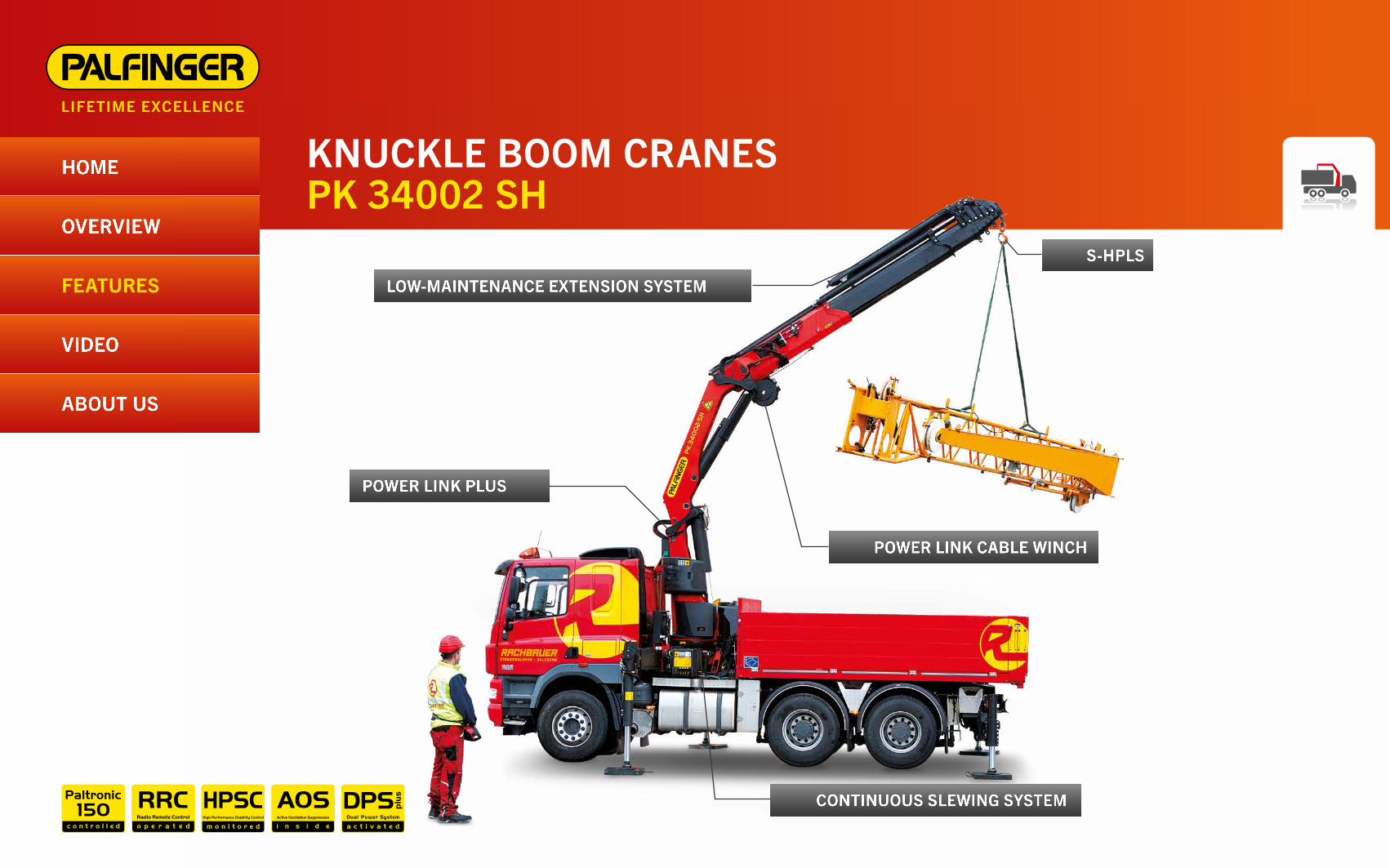
LOW-MAINTENANCE EXTENSION SYSTEMFEATURES
HOME
OVERVIEW
ABOUT US
VIDEO
S-HPLS
POWER LINK PLUS
CONTINUOUS SLEWING SYSTEM
POWER LINK CABLE WINCH
LOW-MAINTENANCE EXTENSION SYSTEMREDUCES SERVICE TIME
With sliding elements made of synthetic material and the high-quality KTL coating, this boom system significantly simplifies service performed by the operator. This saves time and money – and protects the environment.

KNUCKLE BOOM CRANESPK 34002 SH
LOW-MAINTENANCE EXTENSION SYSTEMFEATURES
HOME
OVERVIEW
ABOUT US
VIDEO
S-HPLS
POWER LINK PLUS
CONTINUOUS SLEWING SYSTEM
POWER LINK CABLE WINCH
POWER LINK CABLE WINCHMORE COMFORT IN CABLE WINCH OPERATION
Characterised by low installation height, it is ideal for working inside buildings and transports with the crane boom unfolded. The Comfort Cable Routing reduces set-up times to a minimum.

KNUCKLE BOOM CRANESPK 34002 SH
LOW-MAINTENANCE EXTENSION SYSTEMFEATURES
HOME
OVERVIEW
ABOUT US
VIDEO
S-HPLS
POWER LINK PLUS
CONTINUOUS SLEWING SYSTEM
POWER LINK CABLE WINCH
CONTINUOUS SLEWING SYSTEMUNRESTRICTED MOVEMENT
More efficient in operation due to faster loading cycles, since the crane can be slewed over a shorter distance. The crane works more efficiently and faster.

KNUCKLE BOOM CRANESPK 34002 SH
LOW-MAINTENANCE EXTENSION SYSTEMFEATURES
HOME
OVERVIEW
ABOUT US
VIDEO
S-HPLS
POWER LINK PLUS
CONTINUOUS SLEWING SYSTEM
POWER LINK CABLE WINCH
POWER LINK PLUSHIGH VARIETY OF USES
With the 12-degree reverse linkage system, you can reach through low door openings and also work inside buildings. Heavy crane work – evenin difficult conditions.

KNUCKLE BOOM CRANESPK 34002 SH
LOW-MAINTENANCE EXTENSION SYSTEMFEATURES
HOME
OVERVIEW
ABOUT US
VIDEO
S-HPLS
POWER LINK PLUS
CONTINUOUS SLEWING SYSTEM
POWER LINK CABLE WINCH
S-HPLSMORE LIFTING POWER WHEN IT IS REALLY NEEDED
S-HPLS is one of the most important functions of the PALTRONIC 150. It is a fully automatic system for increasing the lifting power. Depending on the need, there is continuous adaptation of the lifting power and speed of the crane.

TO US, “LIFETIME EXCELLENCE” MEANS SEEING TOP PERFORMANCE AS A MINIMUM REQUIREMENT.LIFETIME EXCELLENCE is our promise. Our core message. Our brand essence. To our customers, it means top performance without compromise. The most cost-effective, reliable and innovative lifting solutions in a global network of expert service partners – for the entire product lifetime.
EXCELLENCE RELIABILITY & EXPERTISE
SUPPORT
EXCELLENCE INNOVATION & FLEXIBILITY
EXPERTISE
PERFORMANCE
SERVICE
EXCELLENCE ECONOMY & EFFICIENCYSAFETY
EXCELLENCE SERVICE & LOCATIONS
ABOUT US
KNUCKLE BOOM CRANESPK 34002 SH
PLAY VIDEO


![Index [] · 2) Telescopic Boom Cranes Telescopic Boom Cranes are used to lift materials •by use of a hydraulic winch and •by raising and lowering the boom. Operation is simple](https://img.pdfslide.us/doc/110x75/5f63559e33ac6b5a586fbd17/index-2-telescopic-boom-cranes-telescopic-boom-cranes-are-used-to-lift-materials.jpg)