Embed Size (px)
Citation preview

KNOWLEDGE FACTORY PRIVATE
LIMITED
CLAIMS 064032AA, 064037AA, BOKO
TRANSFER, 064033AA, 006548AA,
006547AA AND 006548AA ,
Geophysical Survey Report
JUNE 2019

1. Contents TERMS OF REFRENCE ............................................................................................................. 4
KEY PROJECT PERSONNEL RESUME..................................................................................... 5
1.1 HISTORICAL AND BACKGROUND INFORMATION ..................................................... 6 1.2 ACCESSIBILITY, CLIMATE, LOCAL RESOURCES, INFRASTRUCTURE AND
PHYSIOGRAPHY ........................................................................................................................... 6 1.3 REGIONAL GEOLOGICAL SETTING ................................................................................ 6 Figure 1 – Regional Geology Map of the Claims area ..................................................................... 7 1.3.1 LOCAL GEOLOGICAL SETTING ........................................................................................ 7 1.3.2 PROSPECTS FOR GOLD MINERALIZATION ................................................................... 7 2 GEOPHYSICAL SURVEYS METHODOLOGY .................................................................. 8 2.1 GROUND MAGNETIC SURVEY ............................................................................................ 9 2.2 MAGNETIC SURVEY INSTRUMENTATION .................................................................... 9 2.3 MAGNETIC DATA PROCESSING ...................................................................................... 9 2.3.1 DISCUSSION ........................................................................................................................ 10 Plate 1 – Coverage of magnetic survey .......................................................................................... 11 2.4 BIBI CLAIM 0064032AA ........................................................................................................ 12 Figure 2 – Total Magnetic Intensity Map showing structures ........................................................ 12 2.4.1. Main Pit Anomaly ................................................................................................................ 12 Figure 3 – Total Magnetic Intensity Map Overlain by Geology Interpretation .............................. 13 2.4.2 A Anomaly ............................................................................................................................ 13 2.4.3 B Anomaly............................................................................................................................. 13 Figure 4 – Derivative Map Overlain by Targets ............................................................................. 14 2.5 IP SURVEY METHODS ...................................................................................................... 14 2.6 IP INSTRUMENTATION .................................................................................................... 14
2.6.1 Survey Parameters…………………………………………………………15
2.7 SURVEY DATA PROCESSING AND PRESENTATION ..................................................... 15 2.7.1 DATA PRESENTATION ..................................................................................................... 15 2.7.2 DATA PROCESSING ........................................................................................................... 15 2.7.2.1 GEOPHYSICAL TECHNIQUES ...................................................................................... 15 2.8 INTERPRETIVE MAP GENERATION .................................................................................. 16 2.9 DISCUSSION OF IP RESULTS FOR CLAIM 064032AA ..................................................... 16 Figure 5 – Chargeability Map showing short strike length targets ................................................. 17 Figure 6 – Resistivity Map showing short strike length targets ...................................................... 17 2.10 Real Section Anomalies .......................................................................................................... 18 Figure 7– Real section chargeability map showing Main Pit Target (hot colour on section) ......... 18 Figure 8 – Real section resistivity map showing a broadened resistivity feature at depth associated
with magnetics and chargeability ................................................................................................... 19 3. BIBI CLAIMS 006547AA AND 006548AA ............................................................................. 19 3.1 BIBI CLAIM 006547AA/006548AA RESULTS ..................................................................... 19 Figure 9 – Reduced to pole magnetic map showing the magnetic domain to the west .................. 20 3.2 BIBI CLAIM 006547AA/006548AA ANOMALY DESCRIPTIONS ..................................... 20 Figure 10 – Residual magnetic map showing the magnetic domain to the west and shear zones .. 21 Figure 11 – Vertical Derivative magnetic map showing the magnetic domain to the west and shear
zones ............................................................................................................................................... 22 Figure 12 – Analytical signal magnetic map showing the magnetic domain SH1 and SH2 as
positive ........................................................................................................................................... 23 4. BIBI CLAIM 0064033AA .......................................................................................................... 23 Figure 13 – Total magnetic Intensity Map showing high magnetic domains to the south and low
magnetic domains to the north (effect of regional geology/trend) .................................................. 24 Figure 14 – Reduced to Pole total magnetic intensity map showing magnetic domains ................ 25 4.1 BIBI CLAIM 64032AA ANOMALY DESCRIPTIONS ......................................................... 25

Figure 15 – Residual of total magnetic Intensity Map showing low magnetic domains interpreted
to be shears ..................................................................................................................................... 26 5. BIBI BOKO TRANSFER CLAIM ............................................................................................. 27 Figure 16 – Total magnetic intensity map showing low magnetic domains interpreted to be shears
........................................................................................................................................................ 28 Figure 17 – Reduced to Pole total magnetic intensity map showing low magnetic domains
interpreted to be shears ................................................................................................................... 29 6. BIBI CLAIM 64037AA.............................................................................................................. 29 Figure 18 –Total magnetic intensity map showing low magnetic domains interpreted to be shears
........................................................................................................................................................ 30 Figure 19 – Reduced to Pole total magnetic intensity map showing low magnetic domains
interpreted to be shears/ high magnetic domains as gabbro............................................................ 30 Figure 20 – Residual of total magnetic intensity map showing low magnetic domains interpreted
to be shears ..................................................................................................................................... 31 6. BIBI CLAIM 006548AA............................................................................................................ 31 Figure 21 –Total magnetic intensity map showing magnetic domains interpreted to be variations in
mineralogy with the andesite .......................................................................................................... 32 7 DISCUSSION OF IP RESULTS FOR CLAIMS 006547AA, 006548AA AND 0064033AA .... 32 Figure 22 –Chargeability anomaly map showing SH1, SH3 and SH5 with section that are
chargeable ....................................................................................................................................... 34 Figure 23 –Resistivity anomaly map showing SH1, SH3 and SH5/with section that are resistive 35 Figure 24 –Resistivity anomaly map showing resistive exposed reef trace .................................... 36 Figure 25 –Chargeability anomaly map showing chargeable central unit ...................................... 36 Figure 26 –Resistivity anomaly map showing resistivity unit associated with the exposed quartz
reef .................................................................................................................................................. 37 Figure 27 –Resistivity anomaly map showing resistivity anomalies at depth ................................ 38

TERMS OF REFRENCE
To carry out ground magnetic survey on the entire block of claims covering
some 53Ha
To carry out IP surveys on selected lines guided by the ground magnetic
survey results
To carry out RSIP at depth levels of up at 100 metres
To provide client with processed ASCII files from the IP survey
To carry out data integration and interpretation
To produce report and recommendation of way forward
The following is a detailed report of the work carried out to satisfy the Terms of
Reference.

KEY PROJECT PERSONNEL RESUME
Tenyears Gumede – Holder of a Masters in Exploration Geophysics degree from the
University of Zimbabwe and ITC, Deft Netherlands. BSc Honours in Physics degree
from the University of Zimbabwe. 19 years industry experience as a
graduate/staff/senior/expatriate geophysicist with Anglo American Corporation for 10
years and expatriate geophysicist for Mineral Search of Africa/Norilsk Nickel
Burundi for 4 years. Involved in a number of Anglo Projects and part of the team that
discovered and evaluated Bubi Gold Mine(Zimbabwe), McKays Gold Mine
(Zimbabwe), WHEN Gold Mine (Zimbabwe). Involved in evaluation of Unki
Platinum Mine and Hunters Road low grade high tonnage nickel deposit in
Zimbabwe. Member of the Geological Society of Zimbabwe, Australian Society of
Exploration Geophysicist and South African Geophysical Association.

1.1 HISTORICAL AND BACKGROUND INFORMATION
The Mberengwa greenstone belt is regarded as one of the richest belts in Zimbabwe
having produced gold since ancient times. Bibi claims are located within such mines
as the Dunbeth, Jumbo, A, B, C mines whose production figures are detailed in
Section 1.4.2. Several reefs have been exploited on a smaller scale as evidenced by
artisanal workings, which are distributed heterogeneously within different lithological
units.
1.2 ACCESSIBILITY, CLIMATE, LOCAL RESOURCES,
INFRASTRUCTURE AND PHYSIOGRAPHY
The prospect area, whose ore can feed into Jumbo Mine, in which a hammer mill is
located, is situated on the northern flank of the main the Ngezi River, above some
1160m above sea level. It is located on a ridge that rises above the general plain. The
prospect is linked directly by roads to Zvishavane, the nearest town and Bulawayo
and is approximately 3km by road from the Mimosa Mine Road.
The main drainage system is Ngezi and Mtshingwe Rivers with the Mtshingwe, have
a relatively straight course, following a fault zone from the Fort Rixon area. From
their confluence, the Ngezi follows the fault line until the effect disappears eastwards
and meandering starts.
The climate is composed of a very hot spell in September, October and recently
November before the rainy season that runs till March commences. Otherwise a very
cold winter in May, June and July is experienced.
1.3 REGIONAL GEOLOGICAL SETTING
The Belingwe greenstone belt comprises two distinct greenstone successions, the
lower 2.9 Ga Mtshingwe and the 2.7Ga Ngezi group. These units consists of
stratigraphic units of intermediate to felsic volcanic and volcanoclastic unit,
ultramafic to mafic lava plain sequence, a conglomerate-shale sedimentary sequence,
and a unit of tectonically imbricated sedimentary and volcanic rocks (see Figure 1).

Figure 1 – Regional Geology Map of the Claims area
1.3.1 LOCAL GEOLOGICAL SETTING
The local geology is mainly the mafic and ultramafic (see map above) being
serpentinized peridotite pyroxenite trending NE SW and gabbroic rocks to the north
cut by peridotite pyroxene consumed in basaltic greenstone and foliated banded and
massive tonalite. The basaltic greenstone is sheared with quartz ridge outcrops on hill
crests.
A lot of artisanal work has been done on the valley side of the claims area targeting
elluvial and alluvial gold nuggets by tribute members. Quartz reef ores are stock piled
on the crest side, not processed perhaps due to poor grades. The outcropping quartz
reefs are as much as 1m, but showing that there could be wider at depth. The quartz
veins pinch and swell giving differential thickness.
1.3.2 PROSPECTS FOR GOLD MINERALIZATION
The claims are approximately 1 and 2.5 miles respectively west of Mberengwa
Bulawayo Road turn-off some few kilometers from C Mine, the largest producer in
the vicinity. 'C' mine had been worked from 1907 to 1951 and production averaged 6g
per ton. The C Mine reef forms a prominent outcrop of quartz which follows the crest

of a low hill, striking E W and dipping 60 degrees S. A dolerite sheet cuts the reef
between the 6 and 7 levels. Little work had been done below this level and values
were generally low. The workings extend over 600m and reach a depth of
approximately 200m.
The mine produced 28937 Oz from 220750T milled and15012 Oz from 199763T of
re-treated sands and slimes
Dunbeth Mine, located 2.5km west of Mberengwa lies on a fine-grained, massive and
blocky greenstone rock. The reef strikes N S and dips west along a distinct fissure
cutting the country. It is reported that 304 Oz of gold were produced from 1896T
milled and from 2560T of sands and 850T of slimes 98 Oz were recovered. This mine
lies some 1.2km SE of Jumbo Mine Claims operated by client.
A high grade deposit in the form of Great Belingwe Mine lies 3.75km SSE of
Mberengwa business centre. The reef occurs in a shear zone that flanks the western
boundary of the serpentinites range in pyroclastic greenstones. Reported production is
20350 Oz from 74002T milled and 2206 Oz from 70120T of sands 5076T of slimes.
In general, the number of operating/producing gold mines per square kilometre is
relatively high compared to other known greenstone belts in Zimbabwe and warrants
further exploration work to map blind orebodies lying at depth. It is important to
notice that a lot of these mine operations were discovered and worked by the ancients,
pre-colonisation, taken over and mined economically after 1890. Human skeletal
material, for example, is document at C Mine under archaeological survey reference
number R 869.
2 GEOPHYSICAL SURVEYS METHODOLOGY
Geophysical surveys involving ground magnetic surveys and Induced Polarisation
Surveys were employed to guide the exploration programme paying particular
attention to the geology over past producing pits.

2.1 GROUND MAGNETIC SURVEY
A detailed ground magnetic survey was done at a 50m line spacing and 5m sample
stations, with infills over more promising/known mineralisation to enable
development of an interpretation framework. The main objective was to map sub-
surface geology and structures that control gold mineralization. Note: magnetic
surveys are not direct detectors of mineralization, but give guidance if the
mineralization is associated with magnetic minerals like pyrhotite, magnetite, and
ilmenite.
2.2 MAGNETIC SURVEY INSTRUMENTATION
The survey utilized a GSM 19 Overhausser magnetometer of sensitivity ±0.01nT as a
roving machine whiles the GSM 19 Proton magnetometer of sensitivity ±0.01nT was
a base machine to monitor diurnal effects of the survey days.
2.3 MAGNETIC DATA PROCESSING
Map Generation
The following data transforms and routines were effected using frequency and space
domain filters in MapInfo Discover Program.
Pole reduction
This transform generates a total field data set whose magnetic anomaly signatures are
commensurate with those at the poles rather than the -60° for the induced
magnetization in the prospect area. The effect is to simplify the magnetic map by
rendering anomaly waveform independent of strike and to generate symmetrical
anomalies over steeply dipping magnetic sources. Anomalies with asymmetric
waveform reflect flatly dipping magnetic sources or with a component of remanent
magnetization.
Gradient Data
Computation of the first vertical derivative in an aeromagnetic survey is equivalent to
observing the vertical gradient directly with a magnetic gradiometer and has the same
advantages, namely enhancing shallow and suppressing deeper sources in addition to
giving a better resolution of closely-spaced ones. Second, third and higher order
vertical derivatives may also be computed to pursue this effect further, but usually the

noise in the data becomes more prominent than the signal at above the second vertical
derivative (Reeves, 2005)
Second vertical derivative further boosts the response of shallow targets but higher
noise levels are experienced. Note: Over isolated bodies, second derivative data has
the advantage that zero level contours approximate contacts of magnetic body,
rendering this data of some significant use in semi-quantitatively outlining the plan
position of stratigraphic units.
Analytical Signal
This is a scalar sum of the vertical and the two horizontal gradients. It yields a wholly
positive bell-shaped anomaly over any magnetic source irrespective of its dip, or
magnetization history and is useful in mapping the strike trace of long magnetic
sources or the centre of plug-like sources.
Image processed data
Relief Shading highlights short wavelength, low amplitude anomalies at shallow
depths in total field and other related data sets. Steep features generate sharp, intense
shadows. Where the azimuth is at a large angle to the strike (perpendicular), the
process allows for the visual confirmation of strike continuity along sectors where
anomalies are poorly developed.
2.3.1 DISCUSSION
The magnetic surveys were processed claim by claim beginning with the main Bibi
Claim (0064032AA). The claim covers the main Bibi pit and is 10Ha in area with its
longer axis being east west. Plate 1 below shows the claim numbers as named by the
Ministry of Mines.
Survey Area
Dimensions 53Hectares
Number of claims 7 gold claims
Comment 5 contiguous claims and 2separate. Claim
0064037AA is distal north

NH
Plate 1 – Coverage of magnetic survey

2.4 BIBI CLAIM 0064032AA
The magnetic survey results, Figure 2, show an E –W trend magnetic high being the
volcanic andesites cut by NW SE structures being interpreted as faults. Magnetically
low zones are interpreted as potential shear zones and on the central east correspond
to a mine out pit to depths of 15m. The Main Pit anomaly is, however N S anomaly
curvilinear at UTM800650/7741900, changing its strike direction to NW SE.
Figure 2 – Total Magnetic Intensity Map showing structures
3 distinct magnetic horizons (see Figures 2), Main Pit, A and B have been mapped
with trough to ambient variation of 9nT, indicating that the technique is mapping
variation in magnetic mineralogy of the regionally mapped greenstone.
2.4.1. Main Pit Anomaly
This is a huge feature that shows as magnetic low from the total field and residual
total field data. It strikes north and very broad interpreted as a splay shear cutting
across the general geological strike. The general shear, Sh, is curvilinear and trends
NW SE cutting through the andesite. The Main Pit anomaly, narrows to the north
having been displaced to the east by a more intermediate magnetic anomaly feature.
Open cast mining covers some 100m over the broad zone but exploration pits
continue to the north and south tracing the anomaly.
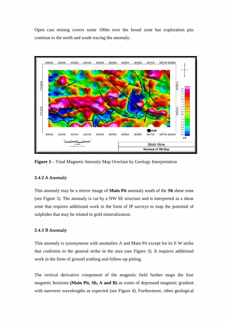
Figure 3 – Total Magnetic Intensity Map Overlain by Geology Interpretation
2.4.2 A Anomaly
This anomaly may be a mirror image of Main Pit anomaly south of the Sh shear zone
(see Figure 3). The anomaly is cut by a NW SE structure and is interpreted as a shear
zone that requires additional work in the form of IP surveys to map the potential of
sulphides that may be related to gold mineralization.
2.4.3 B Anomaly
This anomaly is synonymous with anomalies A and Main Pit except for its E W strike
that conforms to the general strike in the area (see Figure 3). It requires additional
work in the form of ground truthing and follow-up pitting.
The vertical derivative component of the magnetic field further maps the four
magnetic horizons (Main Pit, Sh, A and B) as zones of depressed magnetic gradient
with narrower wavelengths as expected (see Figure 4). Furthermore, other geological

structures that dissect the main anomalies are prominent and their influence in
mineralization cannot be ignored.
Figure 4 – Derivative Map Overlain by Targets
2.5 IP SURVEY METHODS
Follow up Induced Polarisation (IP) surveys (gradient and real section IP
configurations) were implemented on more prospective ground to identify potential
pitting/trenching and drill targets.
2.6 IP INSTRUMENTATION
The IP surveying was conducted using an IRIS IP system, in both single and multi-
gradient array 2-D mode to survey different pseudo-depth levels. The potential
electrode spacing was set to 25 metres to a depth slice of 50m, 75m, and 50m to a
depth slice of 100m and 125m while along line sampling was set at 25m for high
lateral resolution.
Survey Area
Dimensions 10 Hectares

2.6.1 Survey Parameters
The area was surveyed using gradient configuration as a reconnaissance survey
following results from the magnetic survey and field observations being potentially
mineralized outcrops. Line 7741950 was surveyed using real section technique to map
the depth extents of the anomalies
2.7 SURVEY DATA PROCESSING AND PRESENTATION
2.7.1 DATA PRESENTATION
The geophysical data from this survey are displayed in several formats and all plan
maps are registered to the Arc 1950, zone 35K, and UTM grid coordinate system to
enable integration with magnetic data.
2.7.2 DATA PROCESSING
2.7.2.1 GEOPHYSICAL TECHNIQUES
IP METHOD
The time domain IP technique energizes the ground surface with an alternating square
wave pulse using two current electrodes. After the transmitter pulse has been
transmitted into the ground via the current electrodes, the IP effect is measured as a
time diminishing voltage at the receiver electrodes during the off time. By passing an
induced current into the ground and measuring the change in voltage with respect to
time, or changes in phase at a given frequency with respect to a reference phase, the
IP effect can be determined. The IP effect is a measure of the amount of polarizable
materials in the subsurface rock. On ideal circumstances, the chargeability responses
are a measure of the amount of disseminated metallic sulphides (pyrite, pyrhotite etc)
in the subsurface rocks and usually the sulphides are associated with gold, nickel
(pentlandite) or other economic minerals.
It is important to note that there are other non economic rock materials that give rise
to IP effects, including some graphitic rocks, clays and some metamorphic rocks
(serpentinite for example). Ambiguity on interpretation in such geological
environments is introduced so, that from a geological point of view, IP responses are
almost never uniquely interpretable.

Also, from the IP measurements the apparent (bulk) resistivity of the ground is
calculated from the input current and the measured primary voltage. IP/Resistivity
measurements are generally considered repeatable within about five percent.
However, they will exceed that if field conditions change due to variable water
content or variable electrode contact. IP/Resistivity measurements are influenced, to a
large degree, by the rock materials nearest the measuring electrodes, and the
interpretation of the traditional pseudo section presentation of IP data in the past have
often been uncertain. This is because stronger responses that are located near surface
could mask a weaker one that is located at depth.
Gradient Array - The gradient array is an efficient setup that can be used for
reconnaissance or detail surface work. This array is a generalization of the
Schlumberger array, and is used for surveying large grids. The size of the receiver
dipoles would be based on the lateral resolution desired. This array provides data with
good penetration, data are easy to interpret, there is less masking by conductive
overburden, lateral resolution is very good, and can use two or more receivers on line
to speed up the survey. Its main drawback is that depth to anomalous bodies cannot be
determined.
Real Section IP is a form of multi-gradient array in which the current electrodes are
moved to increase depth of observation. The configuration has the advantage that the
polarisable body attitude can be estimated from the pseudo section, making
interpretation straight forward compared to pole-dipole, dipole-dipole data.
2.8 INTERPRETIVE MAP GENERATION
Gridded gradient array chargeability and resistivity maps on plan view were created to
aid in identifying targets (see Figure 5). The plan-view maps are essential to
determine possibility of structures and correlation with magnetic survey
results/interpretation, trenching to improve geological understanding of the area.
2.9 DISCUSSION OF IP RESULTS FOR CLAIM 064032AA

A strongly chargeable feature is mapped corresponding with the Main Pit magnetic
anomaly indicating that the ores mined were sulphidic at depth (see Figure 5). The
anomaly is broken along strike indicating the effect of NW SE structures mapped by
the magnetic survey (see Figure 5).
Figure 5 – Chargeability Map showing short strike length targets
Figure 6 – Resistivity Map showing short strike length targets

Subordinate chargeability anomalies have also been mapped to the west. These
subordinate anomalies have a NS orientation that cuts across the A magnetic anomaly.
The chargeability anomaly over the Main Pit is associated with a high resistivity
anomaly, a condition necessary for disseminated sulphides in quartz material. The
mined out reef at surface is a quartz vein that is oxidized (see Figure 6). The
resistivity anomaly over the Main Pit is composed of 3 short strike length anomaly
indicating the potential of separate reefs and structure .within the main body
2.10 Real Section Anomalies
The real section IP line maps the Main Pit Zone as a steeply dipping anomaly with an
increased chargeability at depths of up to 100m. The anomaly is associated with a
resistivity anomaly that broadens with depth.
Figure 7– Real section chargeability map showing Main Pit Target (hot colour on section)
The chargeability anomaly section 7741950N (see Figure 7) shows a textbook depth
anomaly of up to 4mV/V coinciding with the low magnetic anomaly that is

interpreted as a shear zone. A corresponding resistivity feature located at
UTM800650/7741950 is also mapped but lies at depth with a dip attitude towards the
west.
Figure 8 – Real section resistivity map showing a broadened resistivity feature at depth
associated with magnetics and chargeability
3. BIBI CLAIMS 006547AA AND 006548AA
The claims are the most southerly with their long axis being north-west south-east
(see Plate 1). Based on the regional geological trend the magnetic and IP survey lines
were oriented east west.
Survey Area
Dimensions 13.9 Hectares
3.1 BIBI CLAIM 006547AA/006548AA RESULTS
A highly magnetic anomaly, perhaps a gabbro unit lies to the north west of the claims
area while the south east is generally subdued in magnetic intensity. An east west

regional magnetic trend is observed subduing the anomalies to the east on the total
magnetic intensity results (see Figure 9).
Figure 9 – Reduced to pole magnetic map showing the magnetic domain to the west
The magnetic feature is some 100nT above the ambient field due to the andesitic
rocks. Similarly the low magnetic features are 20nT below the ambient magnetic field
of the area.
3.2 BIBI CLAIM 006547AA/006548AA ANOMALY DESCRIPTIONS
SH1 ANOMALY
It is a north south low magnetic anomaly that has been cut by north-west south-east
and north-east south-west structures. It is interpreted to be a shear zone. Conjugate,
near east west shear zones have been mapped. Remnants of magnetic features are also
observed within the interpreted shear zones being zones where magnetite has not been
completely destroyed (see Figure 10 and 11).

Figure 10 – Residual magnetic map showing the magnetic domain to the west and shear
zones
SH2 ANOMALY
The anomaly lies north-west of the claims area, north of the interpreted gabbro. It is a
low magnetic feature synonymous to SH1 anomaly to the south. The anomaly pinches
and swells along its curvilinear strike direction, which is east west to the south and
north south to the north. East West structures dissecting the anomaly have been
mapped. SH1 and SH2 magnetic anomalies are targets for gold mineralization. Their
conjugate anomalies are particularly important in gold mineralization. The younger
structures cutting through these two magnetic anomalies may also be targets for gold
mineralization. Hydrothermal fluids migrate along weaker zones like shears and
structures and if mineralized, precipitate gold along them.
The anomalies were further targeted with resistivity/induced polarization surveys.
Trenching and pitting over these anomalies is recommended.

Figure 11 – Vertical Derivative magnetic map showing the magnetic domain to the west and
shear zones
A north south structural fabric cut by north-east south-west faults has also been
mapped (see Figures 10, 11, 12). The mapped faults are f1and f2 with a north-east
south-west orientation and f3 and f5 being north south. The f4 fault has a north-west
south-east orientation. The faults dissect the mapped shear SH1. The gabbro anomaly
is massive and not affected by the faults system indicating that it may be later than the
faults.
Two east west structures have been identified further to the north, one dissecting the
SH2 anomaly.

Figure 12 – Analytical signal magnetic map showing the magnetic domain SH1 and SH2 as
positive
4. BIBI CLAIM 0064033AA
Survey Area
Dimensions 7.6 Hectares
The block consists of highly magnetic units to the south, interpreted to be potential
gabbro formation and low magnetic strength features to the north that is related to
potential shears. A regional north south magnetic trend is identified from the total
magnetic intensity map and subdues the residual geology related anomalies. The
highly magnetic anomalies are some 120nT above the ambient magnetic field due to
andesitic rocks, while the low magnetic units are some mere 20nT below the ambient
field.
The magnetic survey has mapped major north-west south-east structures cutting east
west geological formations (see Figure 13 and 14).

Figure 13 – Total magnetic Intensity Map showing high magnetic domains to the south and
low magnetic domains to the north (effect of regional geology/trend)

Figure 14 – Reduced to Pole total magnetic intensity map showing magnetic domains
4.1 BIBI CLAIM 64032AA ANOMALY DESCRIPTIONS
SH3 ANOMALY
On the residual geology magnetic map, the unit is mapped as a low magnetic feature
striking east west and cut by two major faults oriented near north south. The unit is
interpreted to be a potential shear zone hosted within the andesites (see Figure 15).

The unit pinches and swells along its strike as it is cut by north-west south-east
structures interpreted as faults.
Figure 15 – Residual of total magnetic Intensity Map showing low magnetic domains
interpreted to be shears

SH4 ANOMALY
The anomaly is the southerly of the low magnetic features with an east west strike and
cut by a series of structures to its east. The structures are major north-west south-east
oriented features that also dissect SH3 anomaly to the north. The unit is interpreted to
be an east west shear zone. It pinches and swells like its counterpart anomalies SH3,
SH2 and SH1.
SH5 ANOMALY
This anomaly is relatively low magnetic intensity and trends north-west south-east. It
is interpreted as a potential shear and intersects with the SH3 anomaly at UTM Arc
1950 800320/7741790. The anomaly is cut by north-east south-west structures that are
potential faults.
The anomalies SH3, SH4 and SH5 require follow-up trenching and pitting. They were
also targeted with resistivity/IP surveys (see Figure 22).
5. BIBI BOKO TRANSFER CLAIM
Survey Area
Dimensions 9.8 Hectares
The claim shares its southerly boundary with the Main Bibi Claim (64032AA) and a
low magnetic feature lies to the north striking east west. The feature’s magnetic
strength is some 10nT below the ambient field of the mapped andesites (see Figure
16).
High magnetic anomalies, 20nT above the ambient magnetic field have been mapped,
interpreted as variations in mineralogical composition of the andesites (compare to
120nT on other claims). The relative high magnetic anomalies are generally north
south trending; narrow and deformed along their strikes (see Figure 16).

Figure 16 – Total magnetic intensity map showing low magnetic domains interpreted to be
shears
SH6 ANOMALY
The anomaly is an east-west feature, synonymous to SH1, SH2, SH3 and SH4,
depleted in magnetic minerals and is interpreted as a potential shear. It is cut by north
south structures and displacement faults (see Figure 16 and 17).
The reduced to pole magnetic results show that the shear may be extending further
south to its south east as evidenced by distorted/deformed magnetic anomaly with
remnant magnetic highs (see Figure 17). These potential extensions need further
investigations by geological mapping and ground truthing.
Trenching and pitting is recommended. The shear zone was further targeted with
resistivity/IP surveys.

Figure 17 – Reduced to Pole total magnetic intensity map showing low magnetic domains
interpreted to be shears
6. BIBI CLAIM 64037AA
Survey Area
Dimensions 10 Hectares
This is the most northerly of the claim, non-contiguous and constituting 10Ha (see
Figure 1. Two major magnetic domains have been mapped, being a more magnetic
feature to the north, juxtaposed to a low magnetic feature to its south. The greater part
of the survey area is ambient magnetic field of 29739nT, being the andesite (see
Figure 18).
The magnetic anomalies have an east west curvilinear trend and cut by north south
and east west structures. The magnetic horizon is some 25nT above the ambient
magnetic field and is potentially a gabbro.
The low magnetic horizon is some 25nT below ambient field and is potentially a shear
zone (see Figures 18, 19 and 20).

Figure 18 –Total magnetic intensity map showing low magnetic domains interpreted to be
shears
Figure 19 – Reduced to Pole total magnetic intensity map showing low magnetic domains
interpreted to be shears/ high magnetic domains as gabbro

Figure 20 – Residual of total magnetic intensity map showing low magnetic domains
interpreted to be shears
6. BIBI CLAIM 006548AA
Survey Area
Dimensions 1.9 Hectares
The prospect is the smallest in size, covering some 1.9Ha and lies east of the Main
Bibi Claim. A highly magnetic feature, curvilinear, cut by north south structures has
been mapped generally oriented east west. The anomaly is 5nT above ambient field
and is interpreted a magnetic variations within the andesites.
Further to the north, an equally oriented low magnetic anomaly, SH7, has also been
mapped juxtaposed to the high magnetic anomaly. The anomaly is some 3nT below
the ambient magnetic field. It is also interpreted as variations within the host andesite
rocks (see Figure 21).

Figure 21 –Total magnetic intensity map showing magnetic domains interpreted to be
variations in mineralogy with the andesite
Due to the size of the block and the anomaly amplitudes, which seem to be
mineralogical variations within the andesite formation, no further geophysical work
was recommended. However ground truthing of these anomalies by a geologist is
recommended
7 DISCUSSION OF IP RESULTS FOR CLAIMS 006547AA, 006548AA AND
0064033AA
Survey Area
Dimensions 22 Hectares
The chargeability anomaly map (see Figure 22) map sections of the interpreted shear
zones (SH1, SH2, SH3, SH4 and SH5 as chargeable. SH1 and SH5 are the promising
shears based on their quantum of chargeability and resistivity. Real section surveys to

a depth of 100 were subsequently carried out to map the depth extents of the
chargeability anomalies.
The chargeable zones with strong resistivity relation are potential areas with
disseminated sulphides in quartz veins.
The interpreted SH5 to the north has chargeability anomalies broken along strike. The
areas are broken by north-north-east, north-north-west and north south structures.
Mineralisation in these part of the claim area is therefore strongly controlled by these
structures.
Similarly, SH1 anomaly to the south is cut by chargeability anomalies that seem to be
oriented in the direction of the mapped structures from magnetic survey (see Figure
22). However, the resistivity anomaly follows the mapped magnetic anomaly along its
strike direction (see Figure 23).
SH4 is cut by the north south chargeability and resistivity anomalies to its east. The
anomaly itself is devoid of any chargeability anomaly and is therefore an
uninteresting target. However, ground truthing is recommended on the interpreted
magnetic anomalies devoid of chargeable parts.

Figure 22 –Chargeability anomaly map showing SH1, SH3 and SH5 with section that are
chargeable

Figure 23 –Resistivity anomaly map showing SH1, SH3 and SH5/with section that are
resistive

A zoomed in resistivity map is shown below as Figure 24. The huge resistivity
anomaly to the west corresponds to a quartz reef that has been worked to some 3m.
Figure 24 –Resistivity anomaly map showing resistive exposed reef trace
Figure 25 –Chargeability anomaly map showing chargeable central unit

The quartz reef is devoid of chargeability anomalies, but its east counterpart (see
Figure 25) shows a north south anomaly associated with SH5 shear.
The real section anomalies are shown as Figures 26 and 27 and map the quartz reef
extensions to depth. The resistivity anomaly feature indicates that the anomaly is
steeply dipping.
Figure 26 –Resistivity anomaly map showing resistivity unit associated with the exposed
quartz reef

Figure 27 –Resistivity anomaly map showing resistivity anomalies at depth
Recommendation and Conclusions
The magnetic survey has been important in mapping structures, faults and shear zones
that are conduits to gold mineralisation. The micro-variation in magnetic strength
within the andesites may be a measure of shearing or mineralogical variations. Six
targets having been identified from magnetics in addition to the Main Pit anomaly on
Bibi Claim 0064032AA. The Bibi Claim is constituted by another chargeability
anomaly to the west of Main Pit cutting across the main magnetic anomaly that strike
east west. The six targets are synonymous in magnetic strength as Main Pit but vary in
chargeability measure.
The resistivity/ IP surveys have mapped a north-west south-east reef on the edge of
the claims to the west associated with a worked quartz reef. A sub-parallel anomaly
east of the exposed quartz working has been identified and require further work. This

reefs has no corresponding IP anomaly. Trenching and pitting is recommended,
priority being resistivity/chargeability anomalies associated with interpreted shear
zones.


![ANNUAL REPORT 2016-17 - KeertiKeerti Knowledge & Skills Limited [ormerly known as “Keerti Knowledge & Skills Private Limited and Keerti Software & Hardware Infotech Private Limited”],](https://img.pdfslide.us/doc/110x75/5e7b6fbde0a21e6f9d34e33d/annual-report-2016-17-keerti-knowledge-skills-limited-ormerly-known-as.jpg)