Embed Size (px)
DESCRIPTION
Knog NERD 9 and 12 Function Computer instruction manual
Citation preview
1
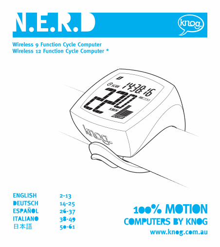
Wireless 9 Function Cycle ComputerWireless 12 Function Cycle Computer *
English 2-13 deutsch 14-25 espaÑol 26-37 Italiano 38-49 日本語 50-61
2CONTENTS
ENGLISH
Anatomy ..................................................................................................................3
Main Unit Setup .......................................................................................................4
Functions .................................................................................................................7
Button and Normal Operations ...............................................................................8
Bike Installation .................................................................................................... 10
Battery Change ...................................................................................................... 12
Care and Maintenance Instructions ....................................................................... 12
The Full Specs ....................................................................................................... 13
* = N.E.R.D Wireless 12 Function Cycle Computer only
3ANATOMY OF A WIRELESS N.E.R.D.
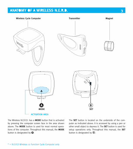
Wireless Cycle Computer Transmitter Magnet
The Wireless N.E.R.D. has a MODE button that is activated by pressing the computer screen face in the area shown above. The MODE button is used for most normal opera-tions of the computer. Throughout this manual, the MODE button is designated by A .
The SET button is located on the underside of the com-puter as indicated above. It is accessed by using a pen or other small object to depress it. The SET button is used for setup operations only. Throughout this manual, the SET button is designated by B .
MODE SET
ACTIVATION AREA
* = N.E.R.D Wireless 12 Function Cycle Computer only
4
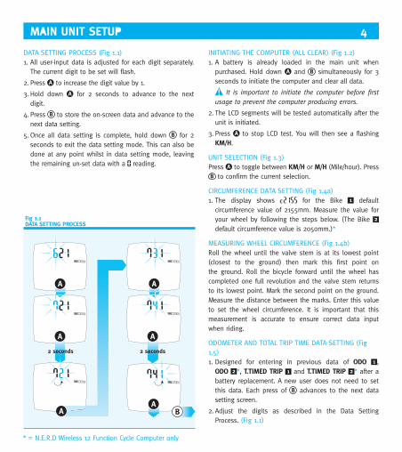
DATA SETTING PROCESS (Fig 1.1)1. All user-input data is adjusted for each digit separately.
The current digit to be set will flash.
2. Press A to increase the digit value by 1.
3. Hold down A for 2 seconds to advance to the next digit.
4. Press B to store the on-screen data and advance to the next data setting.
5. Once all data setting is complete, hold down B for 2 seconds to exit the data setting mode. This can also be done at any point whilst in data setting mode, leaving the remaining un-set data with a reading.
INITIATING THE COMPUTER (ALL CLEAR) (Fig 1.2) 1. A battery is already loaded in the main unit when
purchased. Hold down A and B simultaneously for 3 seconds to initiate the computer and clear all data.
It is important to initiate the computer before first usage to prevent the computer producing errors.
2. The LCD segments will be tested automatically after the unit is initiated.
3. Press A to stop LCD test. You will then see a flashing KM/H.
UNIT SELECTION (Fig 1.3)Press A to toggle between KM/H or M/H (Mile/hour). Press B to confirm the current selection.
CIRCUMFERENCE DATA SETTING (Fig 1.4a)1. The display shows for the Bike 1 default
circumference value of 2155mm. Measure the value for your wheel by following the steps below. (The Bike 2 default circumference value is 2050mm.)*
MEASURING WHEEL CIRCUMFERENCE (Fig 1.4b) Roll the wheel until the valve stem is at its lowest point (closest to the ground) then mark this first point on the ground. Roll the bicycle forward until the wheel has completed one full revolution and the valve stem returns to its lowest point. Mark the second point on the ground. Measure the distance between the marks. Enter this value to set the wheel circumference. It is important that this measurement is accurate to ensure correct data input when riding.
ODOMETER AND TOTAL TRIP TIME DATA SETTING (Fig 1.5)1. Designed for entering in previous data of ODO 1 ,
ODO 2 *, T.TIMED TRIP 1 and T.TIMED TRIP 2 * after a battery replacement. A new user does not need to set this data. Each press of B advances to the next data setting screen.
2. Adjust the digits as described in the Data Setting Process. (Fig 1.1)
MAIN UNIT SETUP
Fig 1.1DATA SETTING PROCESS
2 seconds 2 seconds
* = N.E.R.D Wireless 12 Function Cycle Computer only
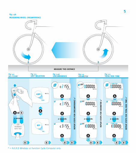
Fig 1.2ALL CLEAR
Fig 1.3UNIT SELECTION
Fig 1.4aCIRCUMFERENCE
Fig 1.5ODOMETER
Fig 1.5TOTAL RIDE TIME
REPE
AT S
TEPS
FOR
CIRC
UM
FERE
NCE
2*
REPE
AT S
TEPS
FOR
TOTA
L RI
DE
TIM
E 2*
REPE
AT S
TEPS
FOR
ODOM
ETER
2*
MEASURE THIS DISTANCE
Fig 1.4b
MEASURING WHEEL CIRCUMFERENCE
LCDSEGMENTSAUTO TEST
3 seconds 2 seconds 2 seconds 2 seconds
5
* = N.E.R.D Wireless 12 Function Cycle Computer only
6
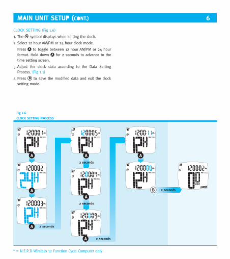
CLOCK SETTING (Fig 1.6)
1. The symbol displays when setting the clock.
2. Select 12 hour AM/PM or 24 hour clock mode.
Press A to toggle between 12 hour AM/PM or 24 hour format. Hold down A for 2 seconds to advance to the time setting screen.
3. Adjust the clock data according to the Data Setting Process. (Fig 1.1)
4. Press B to save the modified data and exit the clock setting mode.
MAIN UNIT SETUP (cont.)
Fig 1.6
CLOCK SETTING PROCESS
2 seconds
2 seconds
2 seconds
2 seconds
2 seconds
* = N.E.R.D Wireless 12 Function Cycle Computer only
7
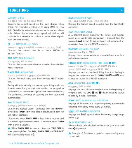
CURRENT SPEED 0.0–199.9 KM/H or 0.0–120.0 Mile/HDisplays the current speed on the main display when riding. The computer registers up to 199.9 KM/H or 120.0 M/H. (Suitable for wheel diameters of 24 inches and above only). When bike motion stops, speed calculations will continue for 4 seconds to confirm no more wheel signals have been transmitted.
: 12H AM/PM OR 24H CLOCK 1:00:00–12:59:59 (AM/PM) or 0:00:00–23:59:59 (24H)Displays the current time in 12 hour AM/PM or 24 hour format.
TRIP DIST: TRIP DISTANCE 0.00–999.99 KM or Mile Displays the accumulated distance travelled from the last RESET operation.
TIMED TRIP: RIDING TIME0:00:00 (H:MM:SS) – 99:59:59(HH:MM:SS)Displays the total riding time from the last RESET opera-tion.
Timing will automatically commence upon riding, and con-tinue to count for 4 seconds after motion has stopped to confirm that no more wheel signals have been transmitted. The additional 4 seconds of counting are then subtracted automatically.
AVG: AVERAGE SPEED0.0–199.9 (KM/H) or 0.0–120.0 (Mile/H)Displays the average speed – calculated from the TRIP DIST divided by TIMED TRIP. This data is accumulated from the last RESET operation.
Displays 0.0 when TIMED TRIP is less than 6 seconds and is updated approximately every 1.2 seconds once TIMED TRIP is over 6 seconds.
When TIMED TRIP is over 100 hours or TRIP DIST is over 1,000km/miles. The AVG , TIMED TRIP and TRIP DIST will automatically reset to .
MAX: MAXIMUM SPEED 0.0–199.9 (km/hr) or 0.0–120.0 (mile/hr)Displays the highest speed recorded from the last RESET operation.
RELATIVE SPEED GAUGEA 16 segment gauge displaying the current and average speed as a side-by-side comparison – indexed from the recorded MAX speed. All information is calculated and ac-cumulated from the last RESET operation.
DIST/DAY: DISTANCE PER DAY* 0.00–999.99 (KM or Mile)Displays the accumulated distance travelled over a 24 hour period (12am–12am).
T.TIMED TRIP: TOTAL RIDING TIME (BIKE 1 , 2 *)0:00:00 (H:MM:SS) – 99:59:59(HH:MM:SS), then 100:00 (HHH:MM) – 9999:59 (HHHH:MM)Displays the total accumulated riding time from the begin-ning of the computer’s use. T. TIMED TRIP 1 and 2 * data cannot be cleared by a RESET operation.
ODO: ODOMETER (BIKE 1 , 2 *)0–999999 (KM or Mile)Displays the total distance travelled from the beginning of computer use. The ODO 1 and 2 * data cannot be cleared to zero by a RESET operation.
SCAN : AUTO SCANNING DISPLAY MODEDisplays all functions in a looped sequence; automatically updating the display mode every 5 seconds.
: LOW BATTERY INDICATORDisplays the
symbol when the battery charge drops
below 2.4V.
: DISPLAY BACKLIGHT*When activated, the display illuminates for 5 seconds each time A is pressed.
Data for all functions is updated approximately every 1.2 seconds.
FUNCTIONS
* = N.E.R.D Wireless 12 Function Cycle Computer only
8
2sec
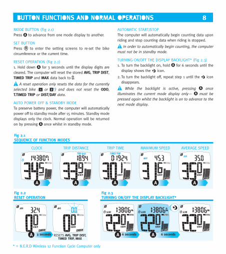
MODE BUTTON (Fig 2.1)Press A to advance from one mode display to another.
SET BUTTONPress B to enter the setting screens to re-set the bike circumference or the current time.
RESET OPERATION (Fig 2.2)1. Hold down A for 3 seconds until the display digits are cleared. The computer will reset the stored AVG, TRIP DIST, TIMED TRIP and MAX data back to .
A reset operation only resets the data for the currently selected bike ( 1 or 2 *) and does not reset the ODO, T.TIMED TRIP or DIST/DAY data.
AUTO POWER OFF & STANDBY MODETo preserve battery power, the computer will automatically power off to standby mode after 15 minutes. Standby mode displays only the clock. Normal operation will be returned on by pressing A once whilst in standby mode.
AUTOMATIC START/STOPThe computer will automatically begin counting data upon riding and stop counting data when riding is stopped.
In order to automatically begin counting, the computer must not be in standby mode.
TURNING ON/OFF THE DISPLAY BACKLIGHT* (Fig 2.3)1. To turn the backlight on, hold A for 6 seconds until the
display shows the icon.
2. To turn the backlight off, repeat step 1 until the icon disappears.
While the backlight is active, pressing A once illuminates the current mode display only— A must be pressed again whilst the backlight is on to advance to the next mode display.
Fig 2.1SEQUENCE OF FUNCTION MODES
Fig 2.2RESET OPERATION
2sec
BUTTON functions and NORMAL OPERATIONS
2sec
Fig 2.3TURNING ON/OFF THE DISPLAY BACKLIGHT*
CLOCK TRIP DISTANCE TRIP TIME MAXIMUM SPEED AVERAGE SPEED
RESETS AVG, TRIP DIST, TIMED TRIP, MAX
3 seconds 6 seconds 6 seconds
* = N.E.R.D Wireless 12 Function Cycle Computer only
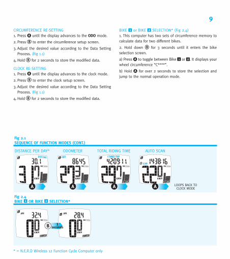
CIRCUMFERENCE RE-SETTING 1. Press A until the display advances to the ODO mode.
2. Press B to enter the circumference setup screen.
3. Adjust the desired value according to the Data Setting Process. (Fig 1.1)
4. Hold B for 2 seconds to store the modified data.
CLOCK RE-SETTING 1. Press A until the display advances to the clock mode.
2. Press B to enter the clock setup screen.
3. Adjust the desired value according to the Data Setting Process. (Fig 1.1)
4. Hold B for 2 seconds to store the modified data.
BIKE 1 or BIKE 2 SELECTION* (Fig 2.4)1. This computer has two sets of circumference memory to calculate data for two different bikes.
2. Hold down B for 3 seconds until it enters the bike selection screen.
a) Press A to toggle between Bike 1 or 2 . It displays your wheel circumference “C****”.
b) Hold A for over 2 seconds to store the selection and jump to the normal operation mode.
Fig 2.4BIKE 1 OR BIKE 2 SELECTION*
2sec
2sec
Fig 2.1
9
Fig 2.1SEQUENCE OF FUNCTION MODES (CONT.)
DISTANCE PER DAY* TOTAL RIDING TIMEODOMETER AUTO SCAN
LOOPS BACK TO CLOCK MODE
3seconds
* = N.E.R.D Wireless 12 Function Cycle Computer only
10
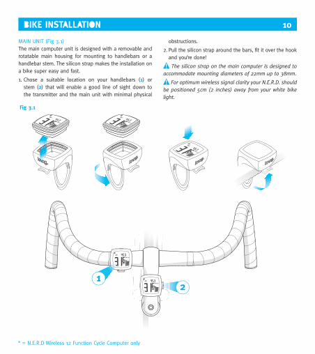
MAIN UNIT (Fig 3.1)The main computer unit is designed with a removable and rotatable main housing for mounting to handlebars or a handlebar stem. The silicon strap makes the installation on a bike super easy and fast.
1. Chose a suitable location on your handlebars (1) or stem (2) that will enable a good line of sight down to the transmitter and the main unit with minimal physical
obstructions.
2. Pull the silicon strap around the bars, fit it over the hook and you’re done!
The silicon strap on the main computer is designed to accommodate mounting diameters of 22mm up to 38mm.
For optimum wireless signal clarity your N.E.R.D. should be positioned 5cm (2 inches) away from your white bike light.
BIKE INSTALLATION
Fig 3.1
* = N.E.R.D Wireless 12 Function Cycle Computer only
11
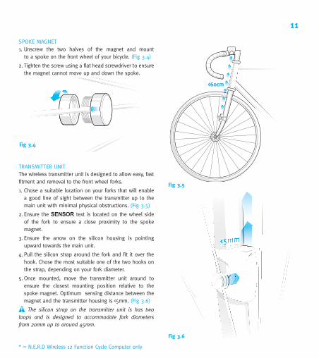
SPOKE MAGNET1. Unscrew the two halves of the magnet and mount
to a spoke on the front wheel of your bicycle. (Fig 3.4)
2. Tighten the screw using a flat head screwdriver to ensure the magnet cannot move up and down the spoke.
TRANSMITTER UNITThe wireless transmitter unit is designed to allow easy, fast fitment and removal to the front wheel forks.
1. Chose a suitable location on your forks that will enable a good line of sight between the transmitter up to the main unit with minimal physical obstructions. (Fig 3.5)
2. Ensure the SENSOR text is located on the wheel side of the fork to ensure a close proximity to the spoke magnet.
3. Ensure the arrow on the silicon housing is pointing upward towards the main unit.
4. Pull the silicon strap around the fork and fit it over the hook. Chose the most suitable one of the two hooks on the strap, depending on your fork diameter.
5. Once mounted, move the transmitter unit around to ensure the closest mounting position relative to the spoke magnet. Optimum sensing distance between the magnet and the transmitter housing is <5mm. (Fig 3.6)
The silicon strap on the transmitter unit is has two loops and is designed to accommodate fork diameters from 20mm up to around 45mm.
Fig 3.4
Fig 3.5
Fig 3.6
11
* = N.E.R.D Wireless 12 Function Cycle Computer only
12
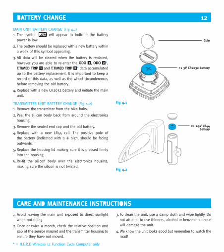
MAIN UNIT BATTERY CHANGE (Fig 4.1)1. The symbol
will appear to indicate the battery
power is low.
2. The battery should be replaced with a new battery within a week of this symbol appearing.
3. All data will be cleared when the battery is replaced, however you are able to re-enter the ODO 1 , ODO 2 *, T.TIMED TRIP 1 and T.TIMED TRIP 2 * data accumulated up to the battery replacement. It is important to keep a record of this data, as well as the wheel circumferences before removing the old battery.
4. Replace with a new CR2032 battery and initiate the main unit.
TRANSMITTER UNIT BATTERY CHANGE (Fig 4.2)1. Remove the transmitter from the bike forks.
2. Peel the silicon body back from around the electronics housing.
3. Remove the sealed end cap and the old battery.
4. Replace with a new LR44 cell. The positive pole of the battery (indicated with a + sign, should be facing outwards.
5. Replace the housing lid making sure it is pressed firmly into the housing.
6. Re-fit the silicon body over the electronics housing, making sure the silicon is not twisted.
BATTERY CHANGE
CARE AND MAINTENANCE INSTRUCTIONS
1. Avoid leaving the main unit exposed to direct sunlight when not riding.
2. Once or twice a month, check the relative position and gap of the sensor magnet and the transmitter housing to ensure they have not moved.
3. To clean the unit, use a damp cloth and wipe lightly. Do not attempt to use thinners, alcohol or benzene as these will damage the unit.
4. We know the unit looks good but remember to watch the road!
Fig 4.1
Fig 4.2
Coin
×1 3V CR2032 battery
×1 1.5V LR44battery
* = N.E.R.D Wireless 12 Function Cycle Computer only
13
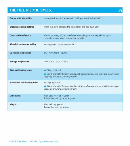
Sensor with transmitter Non-contact magnet sensor with analogue wireless transmitter
Wireless sensing distance 55cm (1.8 feet) between the transmitter and the main unit.
Cross talk/interference Within 40cm (15.8”), no interference by 2 bicycles carrying similar cycle computers, even when ridden side by side.
Wheel circumference setting 1mm-3999mm (1mm increments)
Operating temperature 0°C - 50°C (32°F - 122°F)
Storage temperature -10°C - 60°C (14°F - 140°F)
Main unit battery power ×1 CR2032 3V cell.
The transmitter battery should last approximately one year with an average usage of around 1.5 hours per day.
Transmitter unit battery power ×1 LR44 1.5V cell.
The transmitter battery should last approximately one year with an average usage of around 1.5 hours per day.
Dimensions Main unit: 53 × 51 × 40mm Transmitter unit: 52 × 27 × 52mm
Weight Main unit: 45 grams Transmitter unit: 39 grams
THE FULL N.E.R.D. SPECS:
* = N.E.R.D Wireless 12 Function Cycle Computer only