Embed Size (px)
Citation preview

Knight Boat:Design of an Autonomous, Homing Surface Vessel
2.017, Spring 2006
Design of Systems Operating in Random EnvironmentsSeth Clark, Evan Karlik, Harry Lichter, Mitul Luhar, Cha-Ling O’Connell,
Roberto Rangel, James Sannino, Nina Young

Diagram of Layout with Components Specified
Boat Layout with Weight and Balance
Compass
Trolling, Steering Motor,
Hydrophone #1
GPS
Large Battery #1
Small Battery #1
Small Battery #2
Board
Transducer Motor
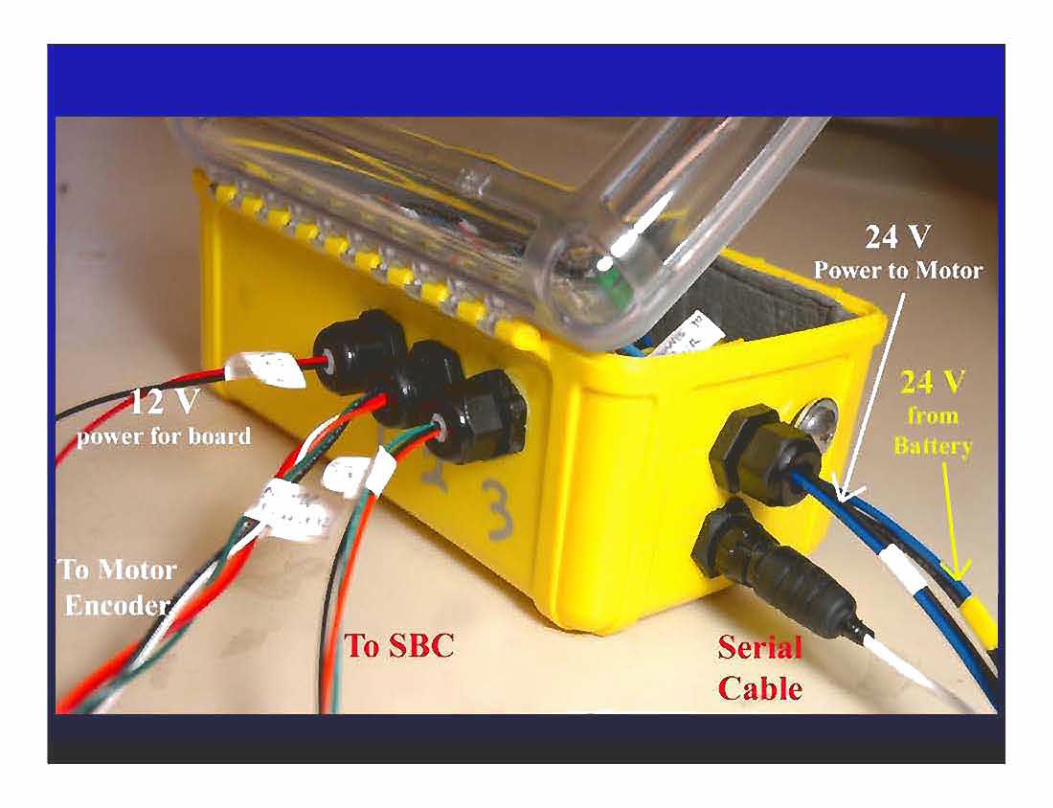
Controller Box
SBC
Large Battery #2
Amplifier
Hydrophone #2 Hydrofoil #2
Hydrophone #3 Hydrofoil #1
And Mount
Acoustics
Wireless

The Team

Mission Objectives
1. Demonstrate homing to subsurface acoustic beacon
2. Sea State 3 conditions3. Navigation in global frame: GPS, compass4. Waypoint autopilot capability

Application
•
• system
AUV tracking
Short-baseline
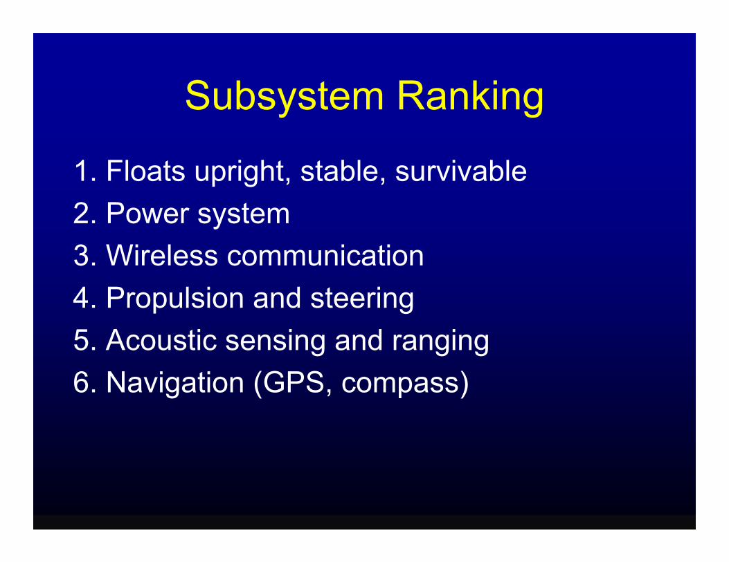
Subsystem Ranking
1. Floats upright, stable, survivable2. Power system3. Wireless communication4. Propulsion and steering5. Acoustic sensing and ranging6. Navigation (GPS, compass)

Hardware: 2005 vs. 2006• Inherited:
– vessel hull (3.66m Pungo 120 kayak)– wireless modems, GPS, compass – thruster, steering motor – hydrophones, transducer
• New to 2006: – single-board computer (SBC), software – motor controller – long-range wireless antenna – circuitry for acoustics and powering

Flotationand
Stability

Design Decision
Primary Objective: Ability to float and remain in an upright position at Sea State 3
• Trimaran design – 3.66m Pungo 120 kayak hull – Two foam outriggers, mounting with 80/20
aluminum extrusion • Outriggers:
– Better overall stability – Larger and more stable base for mounting
hydrophones

Diagrams of Outrigger Design
Rendered Image

Diagrams of Outrigger Design
Two 0.15m x 0.20m x 0.89m foam blocks sculpted and Side Viewtapered for better streamlining, coated with fiberglass.

Diagrams of Outrigger Design
Rear View
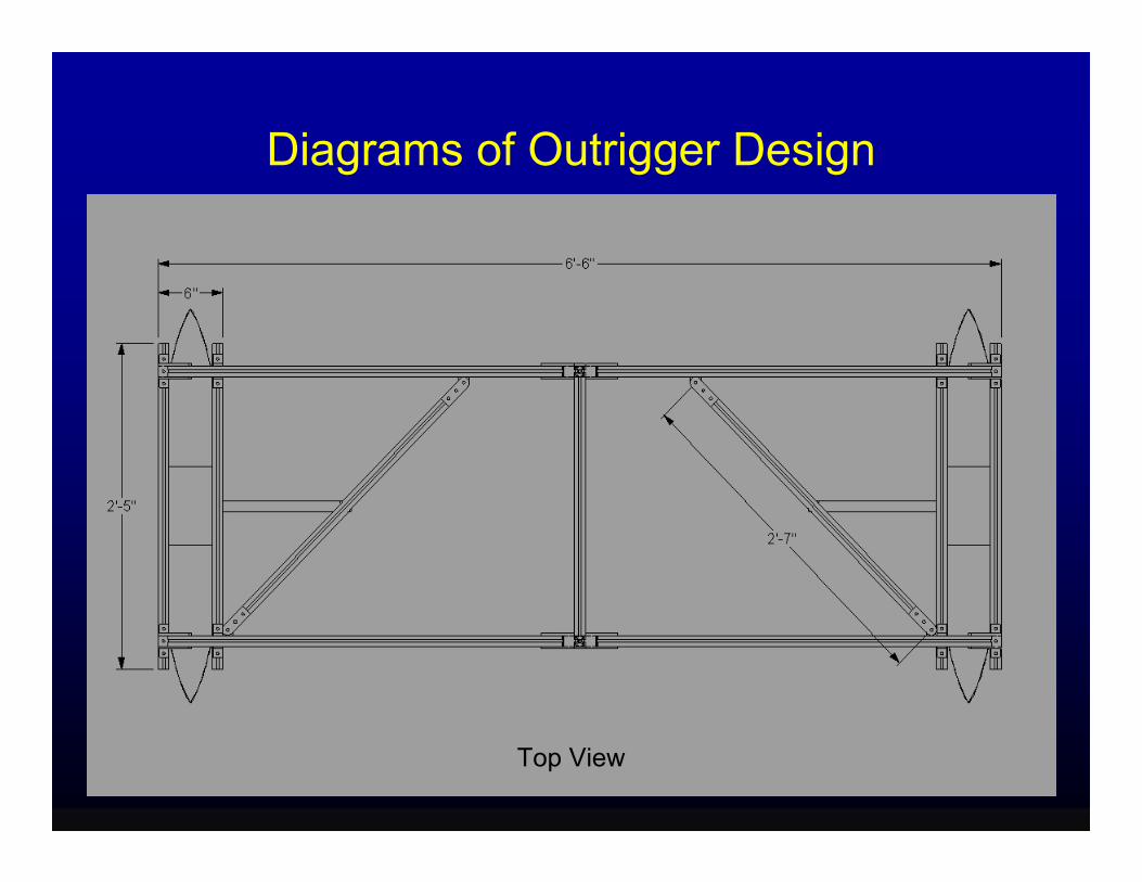
Diagrams of Outrigger Design
Top View

Hydrophone Mounting
• Hydrofoil-shaped fin will be vertically inserted through outriggers
• Hydrophones vertically mounted within the hydrofoil fins. – hydrophones are toroidal – grill carved into the lower portion of the fin

Kayak with Outriggers Mounted

Stability Tests
• Simulated version of the final hull/outrigger system
• Inclining experiment– hull/outrigger design much more stable than the
monohull version
• Initial condition response experiment– displayed the outriggers’ ability to quickly stabilize
the kayak

Mock-up Hull/Outrigger System used in Stability Tests
Mock-up Design in Tow Tank Mock-up Outrigger Design

Inclining Experiment• Determine magnitude of the righting moment at
different angles • 1.5m aluminum bar was attached to the kayak 1.6m
forward of the stern • 72 kg of ballast added • Digital level • Vessel inclined with weights
– up to 89Nm.
Weights were added at a known distance to create an applied moment. The angle of heel
was then measured.

Inclining Experiment: Data
No. Weights Weight (N) Moment (NM) Roll Trial 1 (Degrees)
Roll Trial 2 (Degrees)
0 0 0 0.2 -0.7
1 23.422 17.00 1.4 0
2 46.84 35.60 2.9 0.8
3 70.262 53.40 4.75 1.8
4 93.684 71.20 6.8 2.7
5 117.106 89.00 8.8 3.6

Inclining Experiment: Monohull

Inclining Experiment: TrimaranResults of Inclining Experiment for Hull With
Outriggers
010
2030
405060
7080
90100
-2 0 2 4 6 8 10
Roll (Degrees)
Mom
ent A
rm (N
m)
Trial 1Trial 2

Comparison of Inclining Experiment Results for Monohull and Multihull Options
0
10
20
30
40
50
60
70
80
90
100
-2 0 2 4 6 8 10 12 14 16
Roll (Degrees)
Mom
ent A
rm (N
m)
Multihull 72kgBallast Trial 1
Multihull 72kgBallast Trial 2Monohull 65kgBallast
Monohull 89 kgBallast
We compared the Monohull and Multihull Designs to pick the more stable option

Inclining Experiment: Conclusions
•Trimaran design superior in terms of stability.
•Monohull design (ballasted with 89 kg) rolled to an angle of 10 degrees after 4.3Nm moment
•Modified outrigger design rolled only 8.8 degrees when a 89.0Nm moment was applied!

Initial Condition Response Experiment
• Accelerometers at two different positions on the kayak
• Outriggers pushed down until the entire foam section submerged
• Kayak springs back from buoyancy• Outriggers provides more stable roll condition
than the monohull design – Rights itself from disturbances of 30 degrees
within 1 sec –Remains stable when forced in opposite directions

Initial Condition Response Experiment
ONE IMPULSE ON IMPULSES ON OUTRIGGER OPPOSITE SIDES
Virtually no ringing - 30˚ Impulses die out within 2 seconds

Trim Table
(Meters) Item x- y- z# Component Name Mass (Kg) position position position
1 *Kayak 22.5 1.83 0 0.15 2 *Motor - Trolling 10.43 1 0 -0.33
3 *Motor -Steering(azumuth) 2 1 0
4 *Large Battery #1 22.68 1.48 0 0.2 5 *Large Battery #2 22.68 2.22 0 0.2 6 *Small Battery #1 2.27 1.67 0.02 7 *Small Battery #2 2.27 1.67 -0.02 8 Wireless 1 2.37 0 9 *Transducer 1.81 1.83 0
10 *Hydrophone #1 1.25 1 0 11 *Amplifier 4.76 2.75 0 12 *GPS 0.45 1.3 0 13 *Compass 0.45 0.48 0

119.67Total Displacement
0.11.921ll28 -0.141.92127
01.830.9126 01.830.91*Waterproofing25 01.830.91it24 01.670.9123 013.1822
-0.92.80.5Outrigger #221 0.92.80.5Outrigger #120
02.810.880/20 rack19 -0.92.81Hydrofoil #218 0.92.81Hydrofoil #117
-0.92.81.25Hydrophone #316 0.92.81.25Hydrophone #215
0.402.816.314 z-position y-position x- position Mass (Kg) Component Name Item #
(Meters)
Motor Contro er Box SBC in waterproof box *Electronics (wires, etc)
*Travel Cover for Cockp*Acoustics Board *Trolling Motor Mount
Outrigger System

27
26
25
24
23
22
21
20
19
18
17
16
15
14
13
12
11
10
9
8
7
6
5
4
3
2
1
Moment Arm*Mass
Item # x y z
41.175 0 3.375
10.43 0 -3.4419
2 0 0
33.5664 0 4.536
50.3496 0 4.536
3.7909 0.0454 0
3.7909 -0.0454 0
2.37 0 0
3.3123 0 0
1.25 0 0
13.09 0 0
0.585 0 0
0.216 0 0
45.64 0 6.52
3.18 0 0
1.5197 0 0
1.6653 0 0
1.6653 0 0
1.6653 0 0
1.92 -0.14 0
1.92 0.1 0
15.525 1-0.04225.1017
Weighted Sum
zyx
LCG 1.88102
TCG -0.000334
VCG 0.129733

Diagram of Layout with Components Specified
Boat Layout with Weight and Balance
Compass
Trolling, Steering Motor,
Hydrophone #1
GPS
Large Battery #1
Small Battery #1
Small Battery #2
Board
Transducer Motor
Controller Box
SBC
Large Battery #2
Amplifier
Hydrophone #2 Hydrofoil #2
Hydrophone #3 Hydrofoil #1
And Mount
Acoustics
Wireless

Trim Table: Hull Characteristics
Area of Waterplane (m^2) 1.45 I_x_kayak (m^4) 0.04 I_x_pontoon (m^4) 0.10 Displacement (kg) 117.67 Volume of Displacement
(m^3) 0.12
BM (m) 1.96 KM (m) 2.00 KG (m) 0.13
KM = KB + BM GM = KM - KG BM = I_x_pontoon/Volume of Displacement KG = VCG KB ~ 0.04m
1.87GM (m) (Metacentric Height)

Motor Control


Thruster Control
• 24V trolling motor is boat’s only thruster• Trolling motor controller simply takes
analog signal of 0-3.1V to control power • The SBC produces analog signal of 0-10V
– voltage divider used to obtain the 0-3.1 volts

Thruster controlled wirelessly

Steering System

Servo Control • two circuit boards control 24V Servo Motor
• serial adaptor board • PICservo motor control board

• two digital control signals sent from SBC to the PICservo board – steady signal to indicate direction
– pulse of at least .2µs for each motor encoder step
• 33 steps/degree on servo motor• SBC counts each step sent to determine
the current motor position

SBC Buffer

NMCtest.exe

PICservo Box

Boat Hardware

Vessel Control

SBC serial ports
keyboard
to screen
digital I/O
on/off/reset
hard drive
fan
analog I/O

CommunicationsSBC
Compass
Antenna
Band Pass Filter
Thruster
Adapter
GPS Modem
Azimuth Motor
Laptop
Low Pass Filter
Sine Generator XR2206
Thruster Controller
Board
Transducer
Transformer
Audio Amplifier
Modulation AD630
Programmable Gain
Amplifier
Hydrophones
Smart Serial
Wireless
PICservo
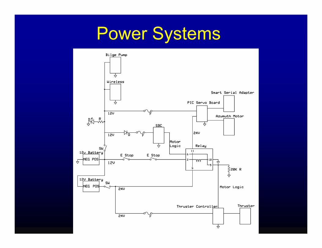
Power Systems


laptop
USB
USB RF
antenna
SBC
RS-232 RF
12 V
9 V
12 V
modem
long-range
modem

Control Interface •
– SBC –
( ial I/O) – laptop –
MAIN
w
r
c
g
a
MENU
Wireless Test
Steer Straight-Line Course
GPS Waypoint
Acoustic Homing
Visual C++
serial modem • CrossCut ser
USB modem
Remote Control

Remote Control
* * * * *REMOTE CONTROL MODE:t - Enter new thrust (0 to 100)s - Enter new motor angle (-90 to 90)c - Jump to Steer Straight-Line Courseu - Updatex - Stop vehicle, return to Mode MenuEnter choice:

Acoustics and
Signal Processing

Acoustic System Overview •
100 m • Short-Baseline System
Objective: Track transponder moving at 1.5 m/s within

Acoustic System Overview
Hardware: • Transducer used to create source signal • Transponder responds • Hydrophones (H1, H2, H3) receive response
Signal Processing and Software • Autocorrelation used to calculate receiving time
differences • Triangulation used to locate transponder

TransducerMost transducers
incapable of <2 kHz
ITC 1001 • Piezo-Electric • Spherical Transducer• Peak TVR [18kHz]: 149 dB re µPa/V @ 1m
i.e. 10(149 - 120)/20 Pa per 1 V input @ 1 m
Figure by MIT OCW.
Directivity Pattern at 18.0 kHz
240
10dB/div
270
300
120
90
60
210 180 150
330 0 30
110
2 10
120
130
140
150
18Frequency in kHz
dB re
µPa
/V @
1m
26 34
Transmitting Voltage Response
Figure by MIT OCW.

Transponder and Hydrophones
• Receive Sensitivity: 100 dB re µPa @ 1m
• Transmit Source Level:
Sonardyne 7656 Transponder
Sonardyne type 7656 Transponder 188 dB re µPa @ 1m
STL SQ03 Hydrophone • Frequency Response:
1-65000 Hz • Receive Sensitivity:
-195 dB V re 1 µPa @ 1m • 40dB pre-amplifier STL SQ03 Hydrophone

Transducer Voltage
• Convenient Transponder Operating Frequency Channel:Source: 20.49 kHzResponse: 29.76 kHz• Can use conventional Audio Amplifiers to fire Transducer
Estimate voltage needed at transducer for 1 km range • Transducer TVR = 145 dB re µPa/V @ 1m • Transponder Sensitivity = 100 dB re µPa @ 1m • Transmission losses at 1 km = 20 log10(1000) = 60 dB • V = 100 + 60 – 145 = 15 dB re 1 V = 5.6 V

Amplification at HydrophoneResponse Signal Estimation: • Transponder Response = 188 dB re µPa @ 1m• Attenuation losses at 1 km= 60 dB • Hydrophone Sensitivity
= -195 dB V re 1 µPa @ 1m + 40 dB (pre-amp) = -155 dB V re 1 µPa @ 1m
Voltage after hydrophone• V = 188 – 60 – 155 = -27 dB V Gain required for 1V signal • Gain = +27 dB V

Electronics: Transducer• SBC digital output is set high
• The XR2206 function generator chip creates a 20.49 kHz signal
• Amplifier transmits high current signal
• Transformer used to change into a high voltage signal
SBC/ TT8 (Digital output)
Sine Generator XR2206
Max 1V
Audio amplifier Sony XM2200
Transducer
(20.49 kHz)
Transformer

Transducer PCB
XR2206Amplitude Control
From SBC D/O
To Amplifer
Power
Frequency Control Input/Output Level Shifting

Frequency Modulation • SBC maximum sampling rate = 45 kHz
• sampling ≥ 2F)Modulation to avoid aliasing (F

Electronics: Hydrophones
• Input signals from hydrophone amplified
• Band Pass filter used to limit the signal to 29.76 kHz
• XR2206 function generator signal at (29.76 + δ) kHz
• Modulation
• 2-pole Butterworth low pass filter
• SBC samples signal
Hydrophones
Programmable Amplifier
Band Pass Filter
ADC on SBC
Function Generator XR2206
(29.76 + δ kHz)
Low Pass Filter (δ kHz)
AD630 Modulator
(Gain 60 dB)
(29.76 kHz)

Hydrophone PCB
Hydrophone
Power
Modulating signal from XR2206
AD630 Modulator
Programmable Amplifier
Output to SBC
Bandpass Filter 2 pole Low-pass Filter

Signal Processing: Autocorrelation
Time difference in the response signal reaching the hydrophones

Software: Triangulation
t1-tt = (1/c)(2R – r1cos (Θ1- Φ))
t2-tt = (1/c)(2R – r2cos (Θ2- Φ))
t3-tt = (1/c)(2R – r3cos (Θ3- Φ))
t1,t2,t3: total travel time to hydrophone
tt: transponder response time

Navigation

Compass – Block Diagram

Compass – Field TestCompass Data
Bea
ring
(deg
ree)
300
250
200
150
100
50
0
-50
-100
-1500 0.5 1 1.5 2 2.5
Time (ms) x 104

GPS
• •
positioning systems •
Determine vessel location Used in combination with acoustic
Map vessel’s traveling history

• (6-40 V DC)
GPS - Specifications
Garmin HVS GPS Unit
• 9 V battery
• 2 serial ports

GPS – Block Diagram

GPS – Field Test

Budget

Item Total Cost SBC $ 1,044.00
SBC LCD screen $ 447.00
LCD Cable $ 65.00
SBC Development Kit & Accessories $ 728.00
SBC Keyboard and Accessories $ 243.00
80GB HD for SBC $ 70.00
CD Drive for SBC $ 30.00
PIC Servo SC Board & Accessories $ 623.55
630JN Modulating Chips $ 59.00
Antenna & Cable $ 265.00
Power systems Hardware & Materials $ 220.95
Express PCB $ 59.00
Cables $ 102.24
80/20 Extrusion $ 300.00
TOTAL $ 4,256.74
Total Cost for Materials Purchased Spring 2006 = $4256.74 Lab consumables provided by OETL < $100.00

MATERIALS COST
Acoustics Materials $5,951.00
SBC and Related Materials $2,627
Navigation Materials $874.00
Wireless Materials $670.00
Power Systems $458.00
Assorted Electrical Components and Cables $161.00
Kayak and Outrigger Accessories $983.00
Motor and Accessories $1,224.00
TOTAL COST $12,948.00

Current State of Project• 22 of 25 milestones completed
• Functional C++ programs created for acoustics and wireless
• Compass interfaced with SBC • GPS interfaced with SBC • Motor control using PICservo and SBC
• SBC fires transducer, accepts hydrophone signals

Future Work• Assembled vessel has motor systems,
power, SBC, wireless • Achieve wireless control of steering motor• Read modulated hydrophone inputs to
SBC • Next term: Install acoustic system,
compass, GPS • Feedback control• Field testing!

Questions?
Comments?