Embed Size (px)
Citation preview
P/N 151161 i
Content
Section 1Introduction ..................................................................................................................................................1
Section 2UL Requirements ..................................................................................................................................2
Section 3System Overview ..................................................................................................................................3
3.1 Terminal Descriptions and Electrical Ratings .............................................................................................33.2 Signal Input Terminals .................................................................................................................................43.3 Notification Output Terminals .....................................................................................................................5
Section 4Installation .....................................................................................................................................................6
4.1 Mounting ......................................................................................................................................................64.2 Wire Routing ................................................................................................................................................74.3 Current Requirements (Standby and Alarm) ...............................................................................................8
4.3.1 Current Drawn From Host Panel ..........................................................................................................84.3.2 Current Drawn from Battery .................................................................................................................8
4.4 Connecting the 5495PAD-2RSE-100 to a Control Panel ..........................................................................104.4.1 Trouble Relay .....................................................................................................................................114.4.2 Class A Supervised Wiring .................................................................................................................12
Class A Output Notification Circuits ..............................................................................................13Class A Supervised Input Circuits ..................................................................................................14
4.4.3 Class B Supervised Wiring .................................................................................................................14Class B Output Notification Circuits ..............................................................................................14Class B Supervised Input Circuits ...................................................................................................15
4.4.4 Ground Fault Detection Enable/Disable Jumper ................................................................................154.5 Battery Connection ....................................................................................................................................164.6 DIP Switch Settings ...................................................................................................................................16
4.6.1 Selecting the Input/Output Configuration ...........................................................................................174.6.2 Setting the Loss of AC Delay .............................................................................................................194.6.3 Setting the Auxiliary Output ...............................................................................................................19
Section 5Connection to Silent KnightPyrotronicsFaraday Panels ..............20
Technical Manuals Online! - http://www.tech-man.com
Model 5495 Distributed Power Module Installation Manual
ii P/N 151161
Section 6Sample Applications ......................................................................................................................33
6.1 Notification Power Applications ................................................................................................................336.2 Non-Resettable Power Application ............................................................................................................366.3 Door Holder Application ...........................................................................................................................37
Section 7Troubleshooting ..................................................................................................................................38
7.1 LEDs ..........................................................................................................................................................387.2 Trouble Conditions ....................................................................................................................................397.3 Removing and Replacing the Control Panel ..............................................................................................40
7.3.1 Removing the Control Panel ...............................................................................................................407.3.2 Replacing the Control Panel ...............................................................................................................40
Appendix AUL Listed Notification Appliances ...............................................................................41
A.1 Notification Appliances .............................................................................................................................41
Appendix BCompatible Notification Appliances ...................................................................... A-1
Technical Manuals Online! - http://www.tech-man.com
P/N 151161 1
Section 1Introduction
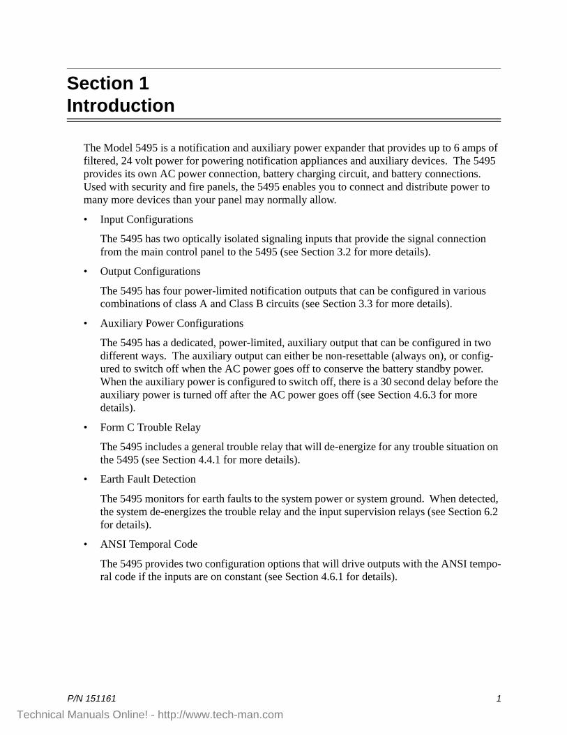
The Model 5495 is a notification and auxiliary power expander that provides up to 6 amps of filtered, 24 volt power for powering notification appliances and auxiliary devices. The 5495 provides its own AC power connection, battery charging circuit, and battery connections. Used with security and fire panels, the 5495 enables you to connect and distribute power to many more devices than your panel may normally allow.
• Input Configurations
The 5495 has two optically isolated signaling inputs that provide the signal connection from the main control panel to the 5495 (see Section 3.2 for more details).
• Output Configurations
The 5495 has four power-limited notification outputs that can be configured in various combinations of class A and Class B circuits (see Section 3.3 for more details).
• Auxiliary Power Configurations
The 5495 has a dedicated, power-limited, auxiliary output that can be configured in two different ways. The auxiliary output can either be non-resettable (always on), or config-ured to switch off when the AC power goes off to conserve the battery standby power. When the auxiliary power is configured to switch off, there is a 30 second delay before the auxiliary power is turned off after the AC power goes off (see Section 4.6.3 for more details).
• Form C Trouble Relay
The 5495 includes a general trouble relay that will de-energize for any trouble situation on the 5495 (see Section 4.4.1 for more details).
• Earth Fault Detection
The 5495 monitors for earth faults to the system power or system ground. When detected, the system de-energizes the trouble relay and the input supervision relays (see Section 6.2 for details).
• ANSI Temporal Code
The 5495 provides two configuration options that will drive outputs with the ANSI tempo-ral code if the inputs are on constant (see Section 4.6.1 for details).
Technical Manuals Online! - http://www.tech-man.com

Model 5495 Distributed Power Module Installation Manual
2 P/N 151161
Section 2UL Requirements
When installed in accordance with NFPA 72 rules, the 5495 can be connected to UL Listed devices suitable for local service.
The 5495 is also listed to meet UL 864 standards and power limiting requirements.
The 5495 is compatible with any UL listed control unit utilizing reverse polarity supervised notification outputs, using 24 VDC regulated outputs.
Technical Manuals Online! - http://www.tech-man.com
System Overview
P/N 151161 3
Section 3System Overview
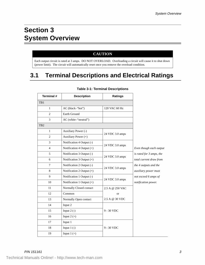
3.1 Terminal Descriptions and Electrical Ratings
CAUTION
Each output circuit is rated at 3 amps. DO NOT OVERLOAD. Overloading a circuit will cause it to shut down (power limit). The circuit will automatically reset once you remove the overload condition.
Table 3-1: Terminal Descriptions
Terminal # Description Ratings
TB1
1 AC (black–“hot”) 120 VAC 60 Hz
2 Earth Ground
3 AC (white–“neutral”)
TB2
1 Auxiliary Power (-)24 VDC 3.0 amps
2 Auxiliary Power (+)
3 Notification 4 Output (-)24 VDC 3.0 amps
4 Notification 4 Output (+) Even though each output
5 Notification 3 Output (-)24 VDC 3.0 amps
is rated for 3 amps, the
6 Notification 3 Output (+) total current draw from
7 Notification 2 Output (-)24 VDC 3.0 amps
the 4 outputs and the
8 Notification 2 Output (+) auxiliary power must
9 Notification 1 Output (-)24 VDC 3.0 amps
not exceed 6 amps of
10 Notification 1 Output (+) notification power.
11 Normally Closed contact 2.5 A @ 250 VAC
or
2.5 A @ 30 VDC
12 Common
13 Normally Open contact
14 Input 2
9 - 30 VDC15 Input 2 (-)
16 Input 2 (+)
17 Input 1
9 - 30 VDC18 Input 1 (-)
19 Input 1 (+)
Technical Manuals Online! - http://www.tech-man.com
Model 5495 Distributed Power Module Installation Manual
4 P/N 151161
3.2 Signal Input Terminals
Terminals 14 through 19 are polarized signal input terminals. They provide the signaling connection from the main panel to the 5495. See Figure 4-2 for more details.
Section 5 shows connections to specific Silent Knight fire and security panels.
The main panel supervises its notification circuits used for communicating with the 5495 the same way it supervises ordinary notification circuits. The signal inputs on the 5495 monitor the polarity of the voltage coming from the main panel’s notification circuits to determine when to operate the notification circuits on the 5495. The 5495 emulates the trouble behavior of a normal notification circuit by breaking the EOL supervision current for internal or output trouble conditions on the 5495.
Note that the 5495 will accurately sense the polarity of the main panel’s notification circuits to drive the outputs whether or not the supervision connection is intact. The following situations will disconnect the EOL supervision at the signal inputs and indicate a trouble condition:
• Low AC power
• Low Battery condition
• Earth ground fault to the system power or system ground
• Auxiliary output power-limited condition
• EOL supervision trouble or power-limited condition at an output
Trouble conditions will not necessarily occur for both inputs when the trouble is specific to a particular output. Only the signal input controlling the output circuit that is in trouble will indicate a trouble condition. Below are examples where both inputs do NOT indicate trouble for a trouble occurring at only one output circuit.
Note: Once the inputs are driven with forward polarity to activate the outputs, the main control panel will not be able to sense trouble conditions through its notification circuit connected to the 5495 input circuits. Use the 5495 trouble relay when it is necessary to monitor trouble conditions and active alarm conditions at the same time.
Section 7 explains the significance of each trouble condition in more detail.
Example 1: If input 1 controls all four outputs, a fault on any output will cause input 1 to indicate trouble. The fault does not affect input 2.
Example 2: If input 1 controls outputs 1 and 2, and input 2 controls outputs 3 and 4, a fault condition on output 3 or 4 will cause input 2 to indicate trouble. The fault does not affect input 1.
Technical Manuals Online! - http://www.tech-man.com
System Overview
P/N 151161 5
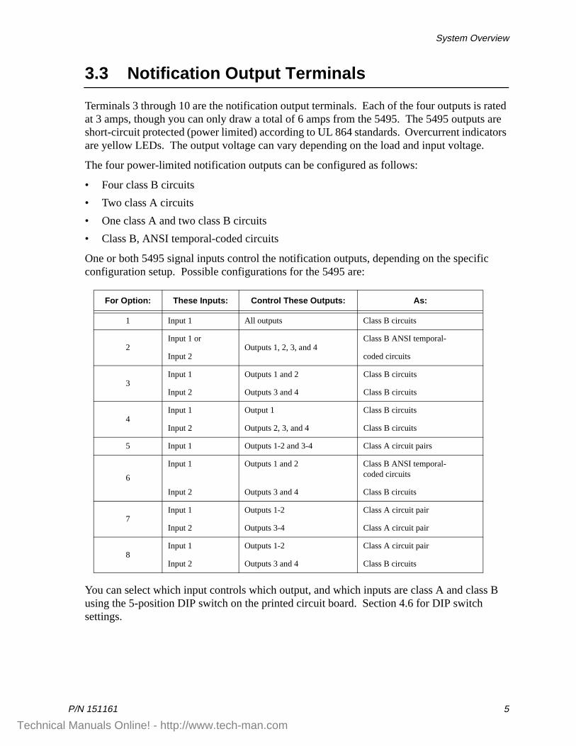
3.3 Notification Output Terminals
Terminals 3 through 10 are the notification output terminals. Each of the four outputs is rated at 3 amps, though you can only draw a total of 6 amps from the 5495. The 5495 outputs are short-circuit protected (power limited) according to UL 864 standards. Overcurrent indicators are yellow LEDs. The output voltage can vary depending on the load and input voltage.
The four power-limited notification outputs can be configured as follows:
• Four class B circuits
• Two class A circuits
• One class A and two class B circuits
• Class B, ANSI temporal-coded circuits
One or both 5495 signal inputs control the notification outputs, depending on the specific configuration setup. Possible configurations for the 5495 are:
You can select which input controls which output, and which inputs are class A and class B using the 5-position DIP switch on the printed circuit board. Section 4.6 for DIP switch settings.
For Option: These Inputs: Control These Outputs: As:
1 Input 1 All outputs Class B circuits
2Input 1 or
Outputs 1, 2, 3, and 4Class B ANSI temporal-
Input 2 coded circuits
3Input 1 Outputs 1 and 2 Class B circuits
Input 2 Outputs 3 and 4 Class B circuits
4Input 1 Output 1 Class B circuits
Input 2 Outputs 2, 3, and 4 Class B circuits
5 Input 1 Outputs 1-2 and 3-4 Class A circuit pairs
6
Input 1 Outputs 1 and 2 Class B ANSI temporal-coded circuits
Input 2 Outputs 3 and 4 Class B circuits
7Input 1 Outputs 1-2 Class A circuit pair
Input 2 Outputs 3-4 Class A circuit pair
8Input 1 Outputs 1-2 Class A circuit pair
Input 2 Outputs 3 and 4 Class B circuits
Technical Manuals Online! - http://www.tech-man.com
Model 5495 Distributed Power Module Installation Manual
6 P/N 151161
Section 4Installation
Before installing the 5495, the AC input must first be wired into the building’s main electrical power through the TB1 terminals (see Figure 4-2). Shut off the electrical power to the 5495, and then complete the general installation of the 5495 using the information in this section.
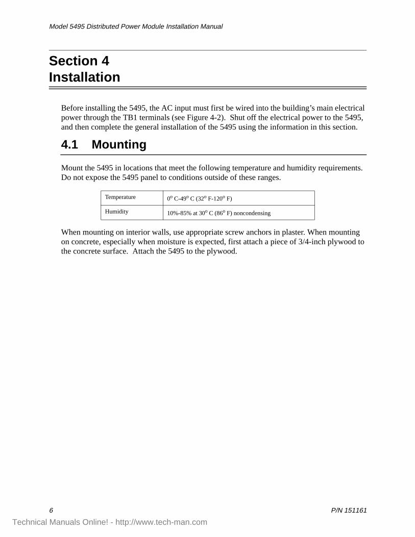
4.1 Mounting
Mount the 5495 in locations that meet the following temperature and humidity requirements. Do not expose the 5495 panel to conditions outside of these ranges.
When mounting on interior walls, use appropriate screw anchors in plaster. When mounting on concrete, especially when moisture is expected, first attach a piece of 3/4-inch plywood to the concrete surface. Attach the 5495 to the plywood.
Temperature 0o C-49o C (32o F-120o F)
Humidity 10%-85% at 30o C (86o F) noncondensing
Technical Manuals Online! - http://www.tech-man.com
Installation
P/N 151161 7
4.2 Wire Routing
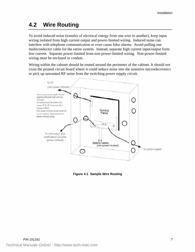
To avoid induced noise (transfer of electrical energy from one wire to another), keep input wiring isolated from high current output and power-limited wiring. Induced noise can interfere with telephone communication or even cause false alarms. Avoid pulling one multiconductor cable for the entire system. Instead, separate high current input/output from low current. Separate power-limited from non-power-limited wiring. Non-power-limited wiring must be enclosed in conduit.
Wiring within the cabinet should be routed around the perimeter of the cabinet. It should not cross the printed circuit board where it could induce noise into the sensitive microelectronics or pick up unwanted RF noise from the switching power supply circuit.
Figure 4-1 Sample Wire Routing
Technical Manuals Online! - http://www.tech-man.com
Model 5495 Distributed Power Module Installation Manual
8 P/N 151161
4.3 Current Requirements (Standby and Alarm)
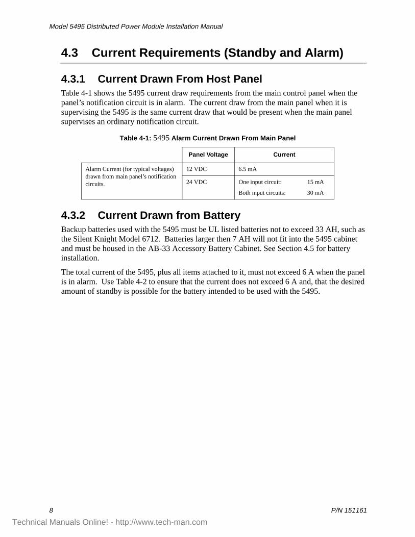
4.3.1 Current Drawn From Host Panel Table 4-1 shows the 5495 current draw requirements from the main control panel when the panel’s notification circuit is in alarm. The current draw from the main panel when it is supervising the 5495 is the same current draw that would be present when the main panel supervises an ordinary notification circuit.
4.3.2 Current Drawn from BatteryBackup batteries used with the 5495 must be UL listed batteries not to exceed 33 AH, such as the Silent Knight Model 6712. Batteries larger then 7 AH will not fit into the 5495 cabinet and must be housed in the AB-33 Accessory Battery Cabinet. See Section 4.5 for battery installation.
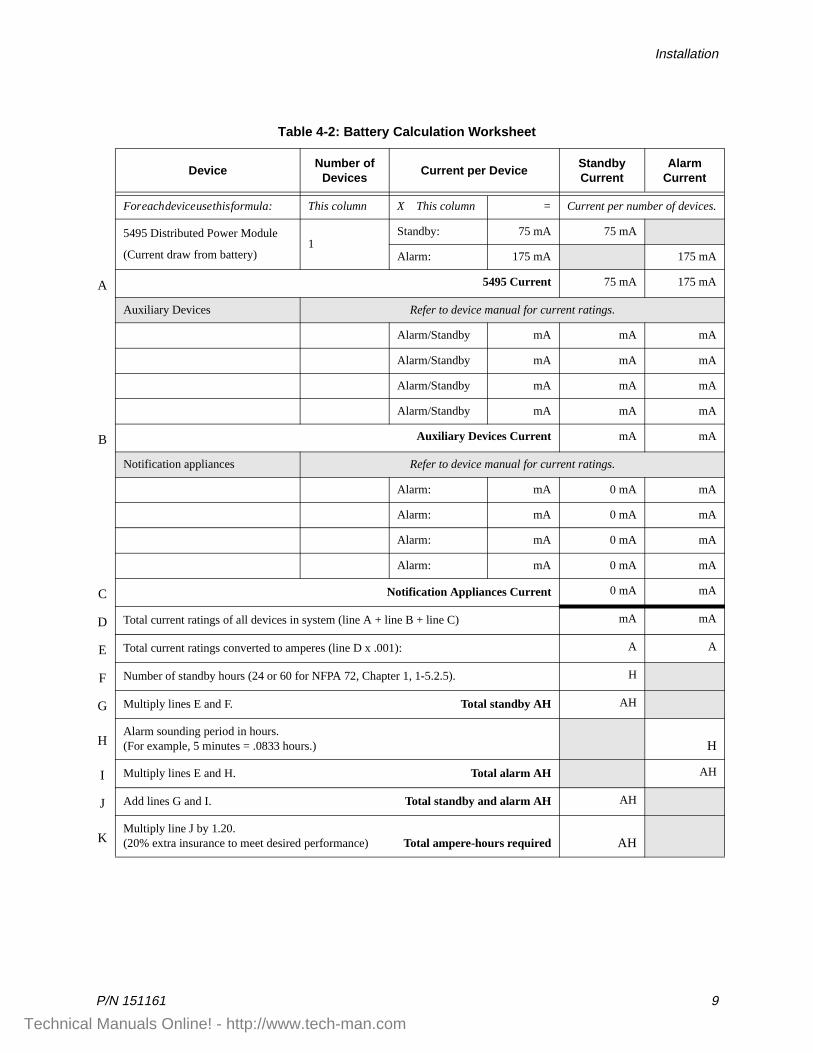
The total current of the 5495, plus all items attached to it, must not exceed 6 A when the panel is in alarm. Use Table 4-2 to ensure that the current does not exceed 6 A and, that the desired amount of standby is possible for the battery intended to be used with the 5495.
Table 4-1: 5495 Alarm Current Drawn From Main Panel
Panel Voltage Current
Alarm Current (for typical voltages) drawn from main panel’s notification circuits.
12 VDC 6.5 mA
24 VDC One input circuit: 15 mA
Both input circuits: 30 mA
Technical Manuals Online! - http://www.tech-man.com
Installation
P/N 151161 9
Table 4-2: Battery Calculation Worksheet
DeviceNumber of
DevicesCurrent per Device
Standby Current
Alarm Current
For each device use this formula: This column X This column = Current per number of devices.
5495 Distributed Power Module
(Current draw from battery)1
Standby: 75 mA 75 mA
Alarm: 175 mA 175 mA
A 5495 Current 75 mA 175 mA
Auxiliary Devices Refer to device manual for current ratings.
Alarm/Standby mA mA mA
Alarm/Standby mA mA mA
Alarm/Standby mA mA mA
Alarm/Standby mA mA mA
B Auxiliary Devices Current mA mA
Notification appliances Refer to device manual for current ratings.
Alarm: mA 0 mA mA
Alarm: mA 0 mA mA
Alarm: mA 0 mA mA
Alarm: mA 0 mA mA
C Notification Appliances Current 0 mA mA
D Total current ratings of all devices in system (line A + line B + line C) mA mA
E Total current ratings converted to amperes (line D x .001): A A
F Number of standby hours (24 or 60 for NFPA 72, Chapter 1, 1-5.2.5). H
G Multiply lines E and F. Total standby AH AH
HAlarm sounding period in hours.(For example, 5 minutes = .0833 hours.) H
I Multiply lines E and H. Total alarm AH AH
J Add lines G and I. Total standby and alarm AH AH
KMultiply line J by 1.20. (20% extra insurance to meet desired performance) Total ampere-hours required AH
Technical Manuals Online! - http://www.tech-man.com
Model 5495 Distributed Power Module Installation Manual
10 P/N 151161
4.4 Connecting the 5495 to a Control Panel
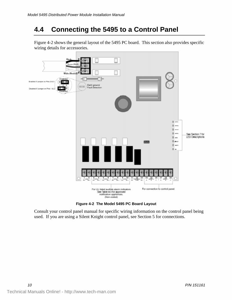
Figure 4-2 shows the general layout of the 5495 PC board. This section also provides specific wiring details for accessories.
Figure 4-2 The Model 5495 PC Board Layout
Consult your control panel manual for specific wiring information on the control panel being used. If you are using a Silent Knight control panel, see Section 5 for connections.
Technical Manuals Online! - http://www.tech-man.com
Installation
P/N 151161 11
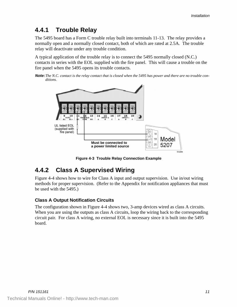
4.4.1 Trouble Relay The 5495 board has a Form C trouble relay built into terminals 11-13. The relay provides a normally open and a normally closed contact, both of which are rated at 2.5A. The trouble relay will deactivate under any trouble condition.
A typical application of the trouble relay is to connect the 5495 normally closed (N.C.) contacts in series with the EOL supplied with the fire panel. This will cause a trouble on the fire panel when the 5495 opens its trouble contacts.
Note: The N.C. contact is the relay contact that is closed when the 5495 has power and there are no trouble con-ditions.
Figure 4-3 Trouble Relay Connection Example
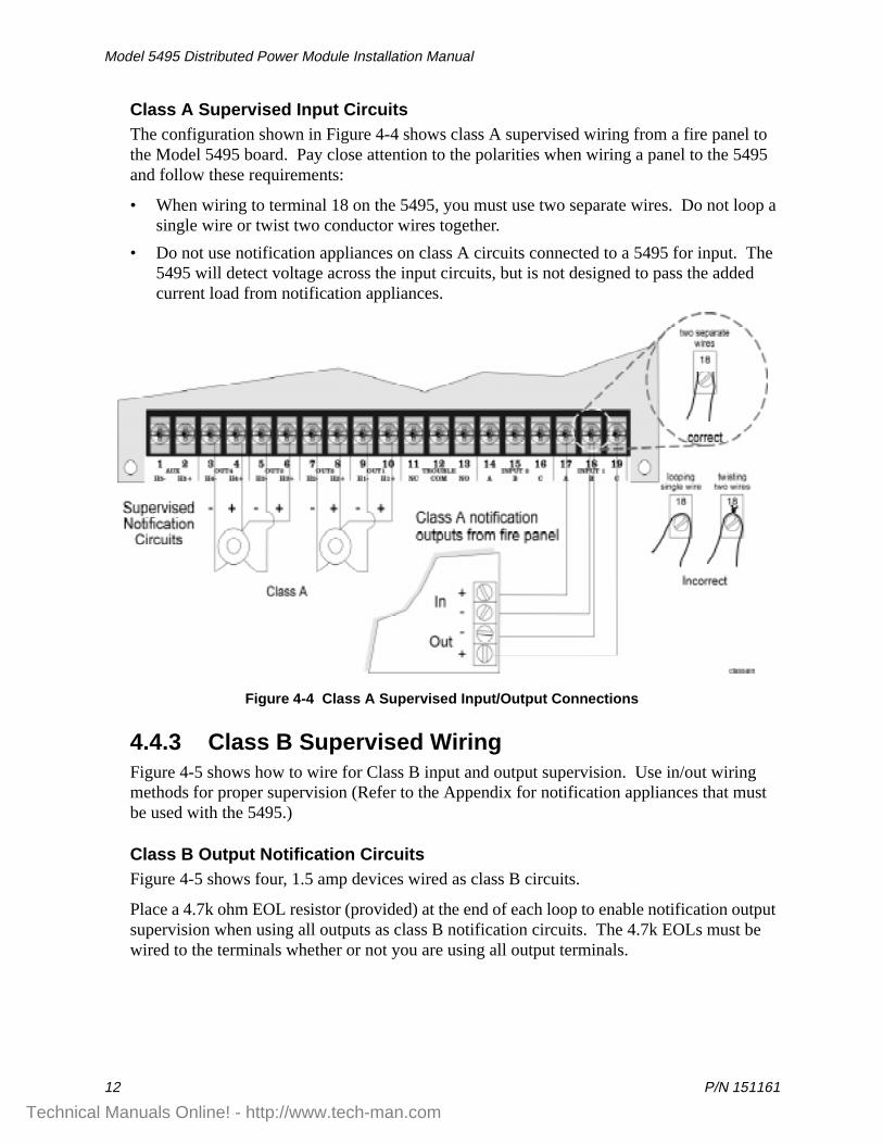
4.4.2 Class A Supervised WiringFigure 4-4 shows how to wire for Class A input and output supervision. Use in/out wiring methods for proper supervision. (Refer to the Appendix for notification appliances that must be used with the 5495.)
Class A Output Notification CircuitsThe configuration shown in Figure 4-4 shows two, 3-amp devices wired as class A circuits. When you are using the outputs as class A circuits, loop the wiring back to the corresponding circuit pair. For class A wiring, no external EOL is necessary since it is built into the 5495 board.
Must be connected toa power limited source
Technical Manuals Online! - http://www.tech-man.com
Model 5495 Distributed Power Module Installation Manual
12 P/N 151161
Class A Supervised Input CircuitsThe configuration shown in Figure 4-4 shows class A supervised wiring from a fire panel to the Model 5495 board. Pay close attention to the polarities when wiring a panel to the 5495 and follow these requirements:
• When wiring to terminal 18 on the 5495, you must use two separate wires. Do not loop a single wire or twist two conductor wires together.
• Do not use notification appliances on class A circuits connected to a 5495 for input. The 5495 will detect voltage across the input circuits, but is not designed to pass the added current load from notification appliances.
Figure 4-4 Class A Supervised Input/Output Connections
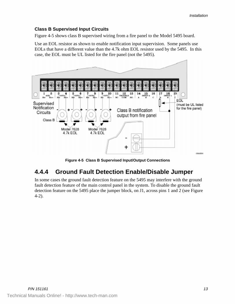
4.4.3 Class B Supervised WiringFigure 4-5 shows how to wire for Class B input and output supervision. Use in/out wiring methods for proper supervision (Refer to the Appendix for notification appliances that must be used with the 5495.)
Class B Output Notification CircuitsFigure 4-5 shows four, 1.5 amp devices wired as class B circuits.
Place a 4.7k ohm EOL resistor (provided) at the end of each loop to enable notification output supervision when using all outputs as class B notification circuits. The 4.7k EOLs must be wired to the terminals whether or not you are using all output terminals.
Technical Manuals Online! - http://www.tech-man.com
Installation
P/N 151161 13
Class B Supervised Input CircuitsFigure 4-5 shows class B supervised wiring from a fire panel to the Model 5495 board.
Use an EOL resistor as shown to enable notification input supervision. Some panels use EOLs that have a different value than the 4.7k ohm EOL resistor used by the 5495. In this case, the EOL must be UL listed for the fire panel (not the 5495).
Figure 4-5 Class B Supervised Input/Output Connections
4.4.4 Ground Fault Detection Enable/Disable JumperIn some cases the ground fault detection feature on the 5495 may interfere with the ground fault detection feature of the main control panel in the system. To disable the ground fault detection feature on the 5495 place the jumper block, on J1, across pins 1 and 2 (see Figure 4-2).
Technical Manuals Online! - http://www.tech-man.com
Model 5495 Distributed Power Module Installation Manual
14 P/N 151161
4.5 Battery Connection
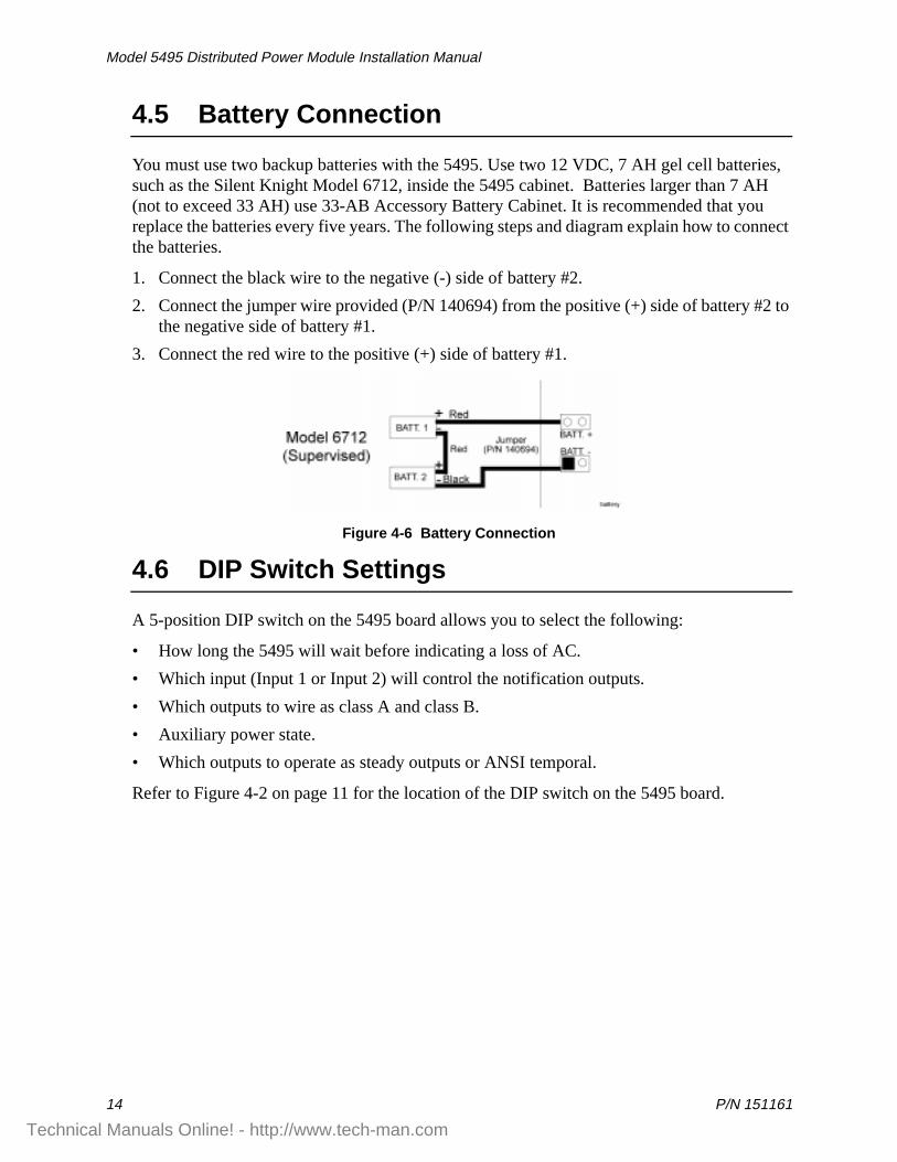
You must use two backup batteries with the 5495. Use two 12 VDC, 7 AH gel cell batteries, such as the Silent Knight Model 6712, inside the 5495 cabinet. Batteries larger than 7 AH (not to exceed 33 AH) use 33-AB Accessory Battery Cabinet. It is recommended that you replace the batteries every five years. The following steps and diagram explain how to connect the batteries.
1. Connect the black wire to the negative (-) side of battery #2.
2. Connect the jumper wire provided (P/N 140694) from the positive (+) side of battery #2 to the negative side of battery #1.
3. Connect the red wire to the positive (+) side of battery #1.
Figure 4-6 Battery Connection
4.6 DIP Switch Settings
A 5-position DIP switch on the 5495 board allows you to select the following:
• How long the 5495 will wait before indicating a loss of AC.
• Which input (Input 1 or Input 2) will control the notification outputs.
• Which outputs to wire as class A and class B.
• Auxiliary power state.
• Which outputs to operate as steady outputs or ANSI temporal.
Refer to Figure 4-2 on page 11 for the location of the DIP switch on the 5495 board.
Technical Manuals Online! - http://www.tech-man.com
Installation
P/N 151161 15
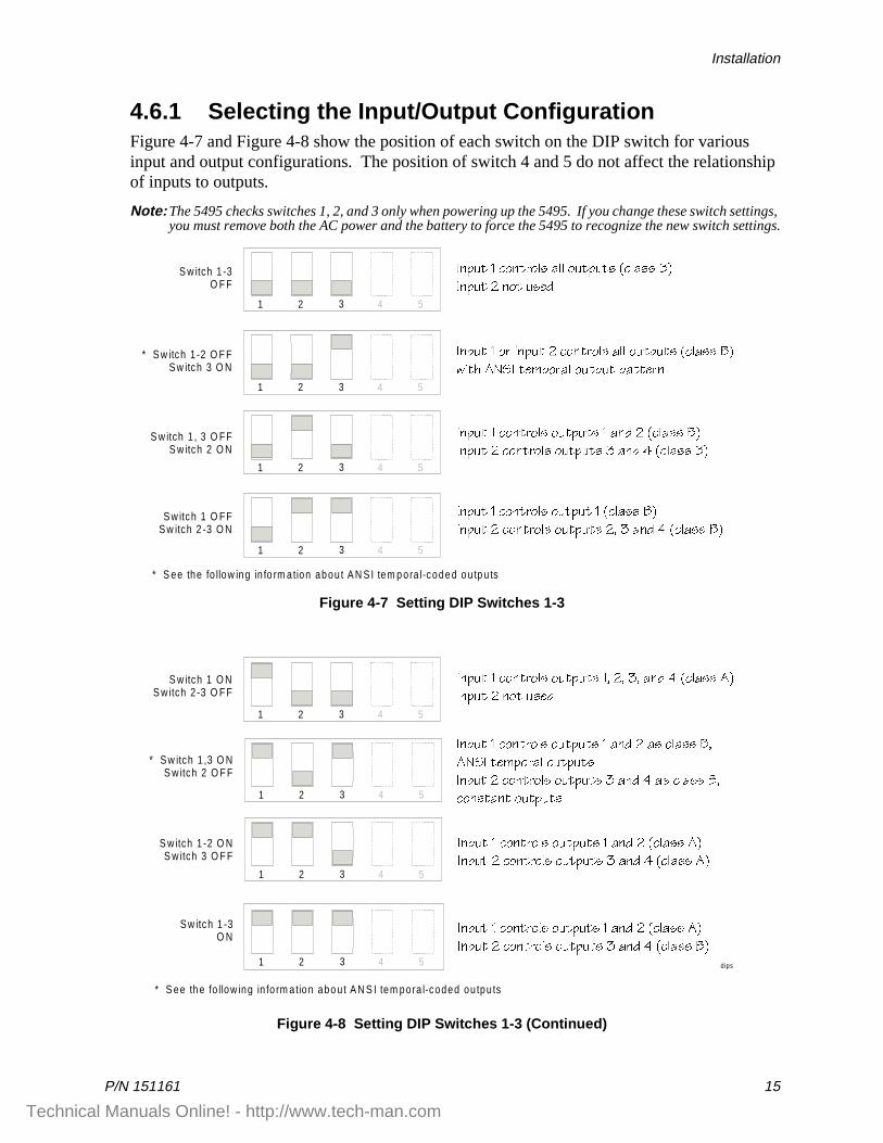
4.6.1 Selecting the Input/Output ConfigurationFigure 4-7 and Figure 4-8 show the position of each switch on the DIP switch for various input and output configurations. The position of switch 4 and 5 do not affect the relationship of inputs to outputs.
Note: The 5495 checks switches 1, 2, and 3 only when powering up the 5495. If you change these switch settings, you must remove both the AC power and the battery to force the 5495 to recognize the new switch settings.
Figure 4-7 Setting DIP Switches 1-3
Figure 4-8 Setting DIP Switches 1-3 (Continued)
1 2 3 4 5
1 2 3 4 5
S w itch 1 -3O F F
* S w itch 1 -2 O F FS w itch 3 O N
S w itch 1 , 3 O FFS w itch 2 O N
1 2 3 4 5
S w itch 1 O FFS w itch 2 -3 O N
1 2 3 4 5
9^`ed ! S_^db_\c Q\\ _ed`edc �S\Qcc 2�
9^`ed " ^_d ecUT
9^`ed ! _b 9^`ed " S_^db_\c Q\\ _ed`edc �S\Qcc 2�
gYdX 1>C9 dU]`_bQ\ _ed`ed `QddUb^
9^`ed ! S_^db_\c _ed`edc ! Q^T " �S\Qcc 2�
9^`ed " S_^db_\c _ed`edc # Q^T $ �S\Qcc 2�
9^`ed ! S_^db_\c _ed`ed ! �S\Qcc 2�
9^`ed " S_^db_\c _ed`edc "� # Q^T $ �S\Qcc 2�
* S ee the fo llow ing in fo rm ation abou t A N S I tem p ora l-code d o u tp u ts
* S w itch 1 ,3 O NS w itch 2 O F F
* S ee th e fo llow ing in fo rm ation abo u t A N S I tem pora l-coded ou tpu ts
S w itch 1 O NS w itch 2 -3 O F F
1 2 3 4 5
1 2 3 4 5
S w itch 1 -2 O NS w itch 3 O F F
1 2 3 4 5
S w itch 1 -3O N
1 2 3 4 5 dips
9^`ed ! S_^db_\c _ed`edc ! Q^T " Qc S\Qcc 2�
1>C9 dU]`_bQ\ _ed`edc
9^`ed " S_^db_\c _ed`edc # Q^T $ Qc S\Qcc 2�
S_^cdQ^d _ed`edc
9^`ed ! S_^db_\c _ed`edc !� "� #� Q^T $ �S\Qcc 1�
9^`ed " ^_d ecUT
9^`ed ! S_^db_\c _ed`edc ! Q^T " �S\Qcc 1�
9^`ed " S_^db_\c _ed`edc # Q^T $ �S\Qcc 1�
9^`ed ! S_^db_\c _ed`edc ! Q^T " �S\Qcc 1�
9^`ed " S_^db_\c _ed`edc # Q^T $ �S\Qcc 2�
Technical Manuals Online! - http://www.tech-man.com
Model 5495 Distributed Power Module Installation Manual
16 P/N 151161
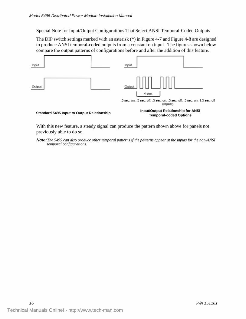
Special Note for Input/Output Configurations That Select ANSI Temporal-Coded Outputs
The DIP switch settings marked with an asterisk (*) in Figure 4-7 and Figure 4-8 are designed to produce ANSI temporal-coded outputs from a constant on input. The figures shown below compare the output patterns of configurations before and after the addition of this feature.
With this new feature, a steady signal can produce the pattern shown above for panels not previously able to do so.
Note: The 5495 can also produce other temporal patterns if the patterns appear at the inputs for the non-ANSI temporal configurations.
Standard 5495 Input to Output RelationshipInput/Output Relationship for ANSI
Temporal-coded Options
Technical Manuals Online! - http://www.tech-man.com
Installation
P/N 151161 17
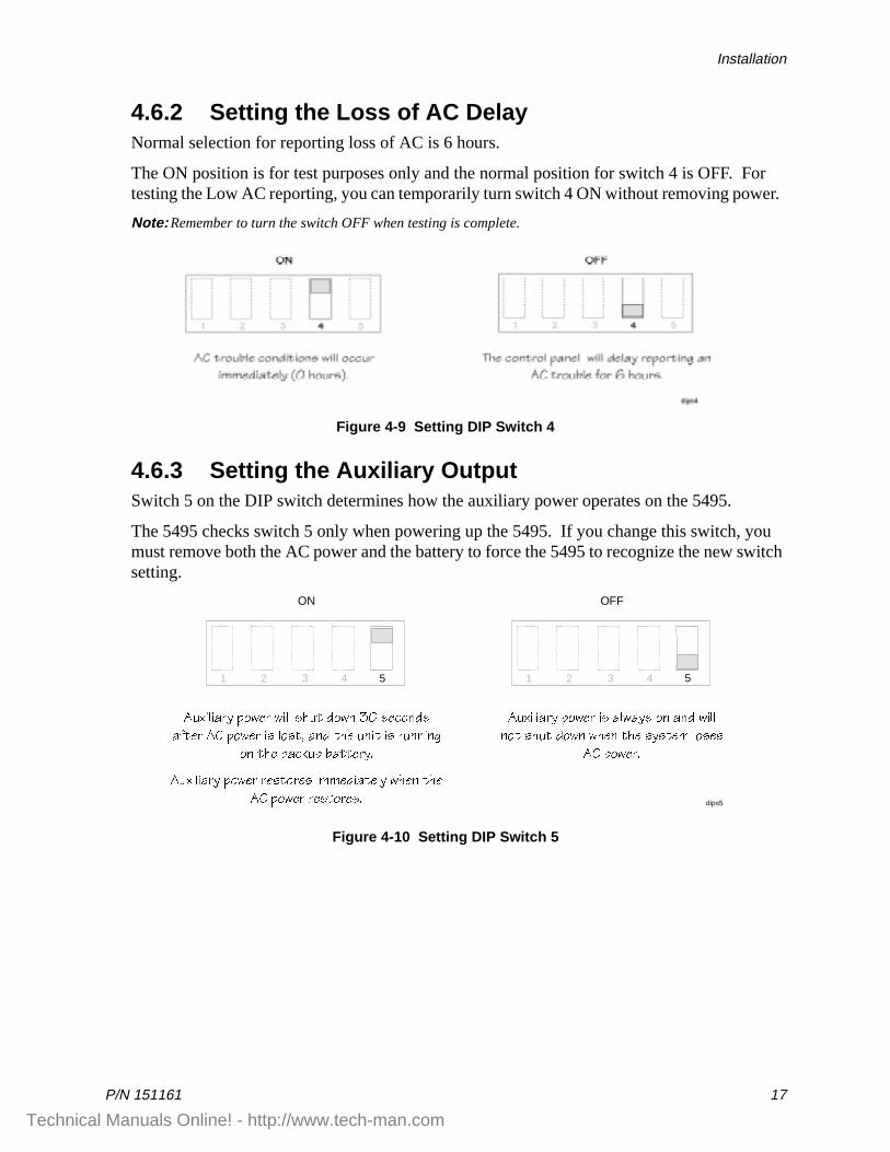
4.6.2 Setting the Loss of AC DelayNormal selection for reporting loss of AC is 6 hours.
The ON position is for test purposes only and the normal position for switch 4 is OFF. For testing the Low AC reporting, you can temporarily turn switch 4 ON without removing power.
Note: Remember to turn the switch OFF when testing is complete.
Figure 4-9 Setting DIP Switch 4
4.6.3 Setting the Auxiliary OutputSwitch 5 on the DIP switch determines how the auxiliary power operates on the 5495.
The 5495 checks switch 5 only when powering up the 5495. If you change this switch, you must remove both the AC power and the battery to force the 5495 to recognize the new switch setting.
Figure 4-10 Setting DIP Switch 5
1 2 3 541 2 3 54
OFFON
dips5
1ehY\YQbi `_gUb Yc Q\gQic _^ Q^T gY\\
^_d cXed T_g^ gXU^ dXU cicdU] \_cUc
13 `_gUb�
1ehY\YQbi `_gUb gY\\ cXed T_g^ # cUS_^Tc
QVdUb 13 `_gUb Yc \_cd� Q^T dXU e^Yd Yc be^^Y^W
_^ dXU RQS[e` RQddUbi�
1ehY\YQbi `_gUb bUcd_bUc Y]]UTYQdU\i gXU^ dXU
13 `_gUb bUcd_bUc�
Technical Manuals Online! - http://www.tech-man.com
Model 5495 Distributed Power Module Installation Manual
18 P/N 151161
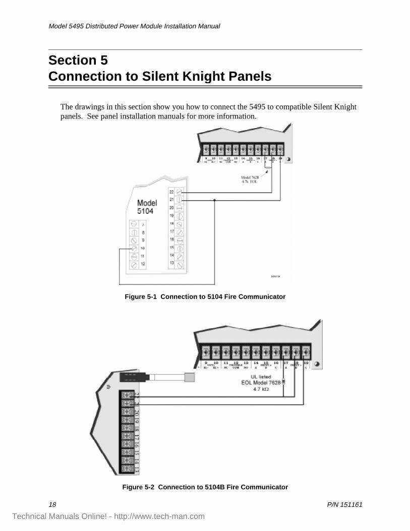
Section 5Connection to Silent Kni ght Panels
The drawings in this section show you how to connect the 5495 to compatible Silent Knight panels. See panel installation manuals for more information.
Figure 5-1 Connection to 5104 Fire Communicator
Figure 5-2 Connection to 5104B Fire Communicator
Technical Manuals Online! - http://www.tech-man.com
Connection to Silent Knight Panels
P/N 151161 19
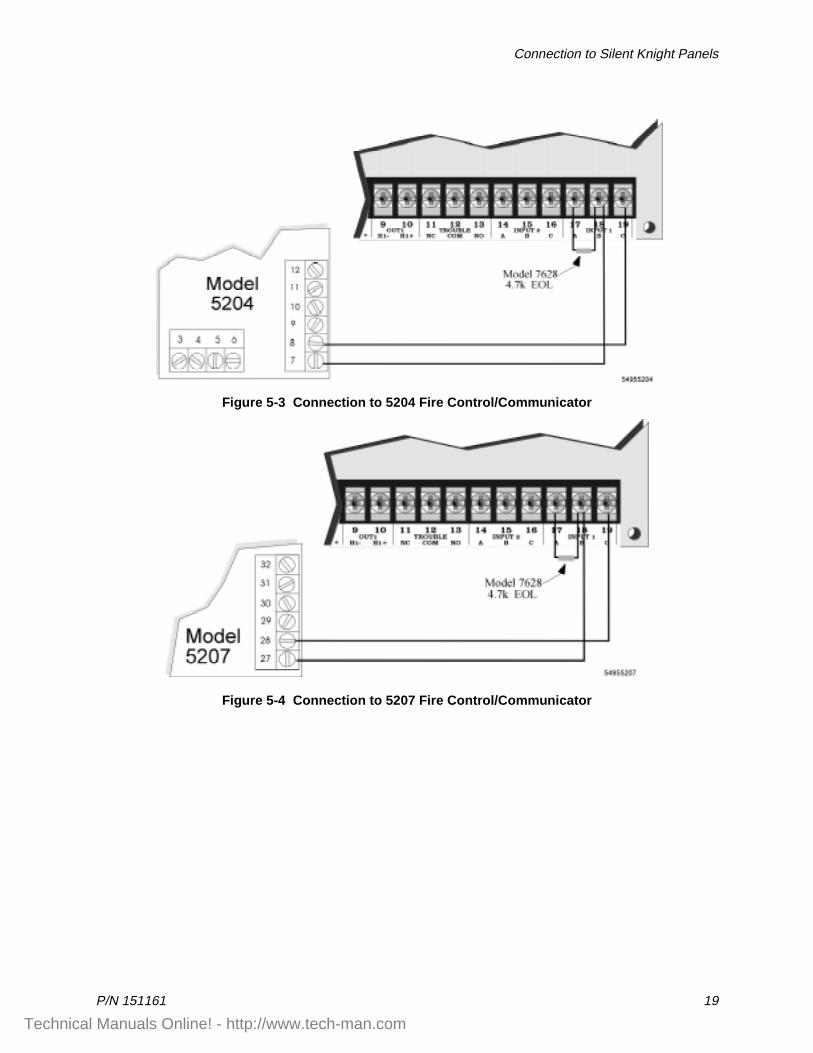
Figure 5-3 Connection to 5204 Fire Control/Communicator
Figure 5-4 Connection to 5207 Fire Control/Communicator
Technical Manuals Online! - http://www.tech-man.com
Model 5495 Distributed Power Module Installation Manual
20 P/N 151161
Section 6
Sample Applications
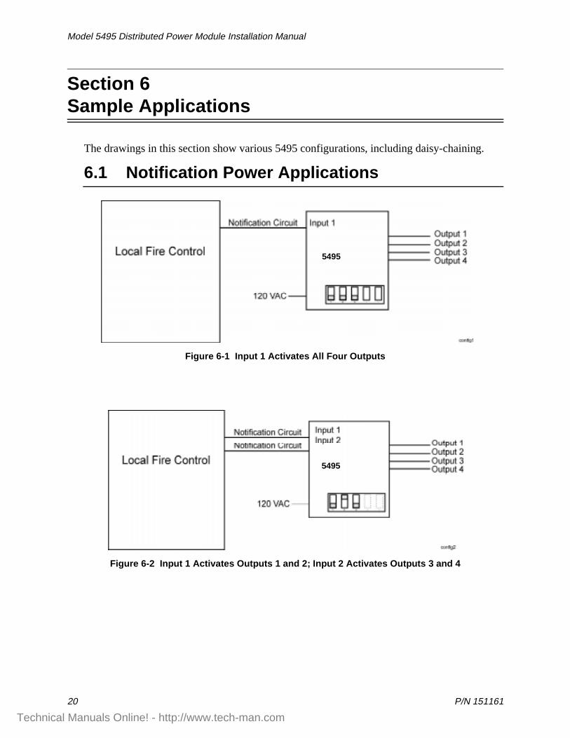
The drawings in this section show various 5495 configurations, including daisy-chaining.
6.1 Notification Power Applications
Figure 6-1 Input 1 Activates All Four Outputs
Figure 6-2 Input 1 Activates Outputs 1 and 2; Input 2 Activates Outputs 3 and 4
5495
5495
Technical Manuals Online! - http://www.tech-man.com
Sample Applications
P/N 151161 21
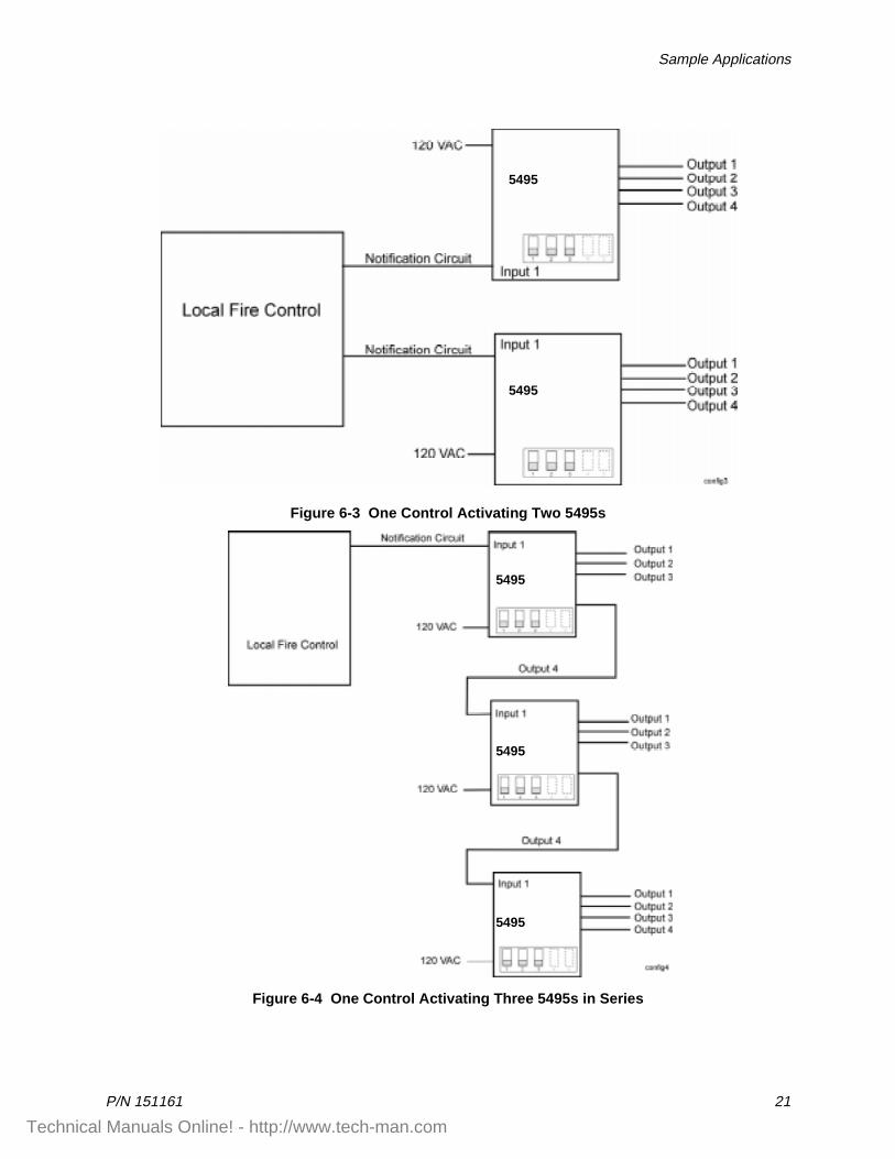
Figure 6-3 One Control Activating Two 5495s
Figure 6-4 One Control Activating Three 5495s in Series
5495
5495
5495
5495
5495
Technical Manuals Online! - http://www.tech-man.com
Model 5495 Distributed Power Module Installation Manual
22 P/N 151161
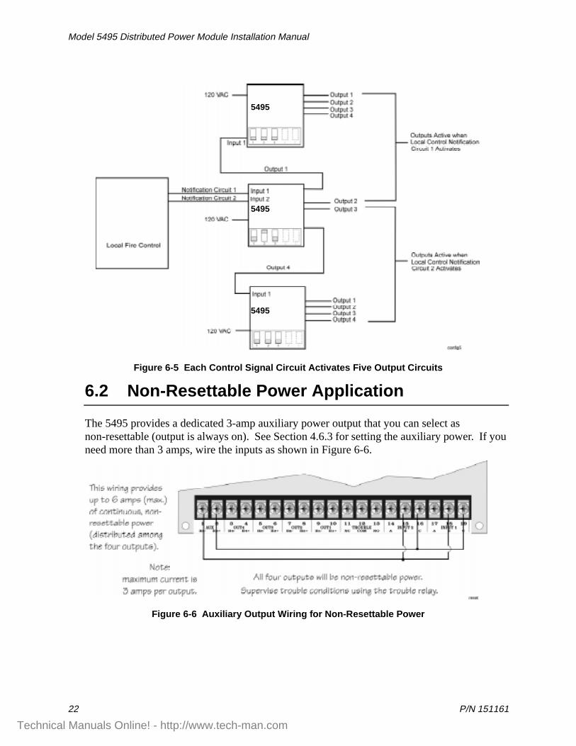
Figure 6-5 Each Control Signal Circuit Activates Five Output Circuits
6.2 Non-Resettable Power Application
The 5495 provides a dedicated 3-amp auxiliary power output that you can select as non-resettable (output is always on). See Section 4.6.3 for setting the auxiliary power. If you need more than 3 amps, wire the inputs as shown in Figure 6-6.
Figure 6-6 Auxiliary Output Wiring for Non-Resettable Power
5495
5495
5495
Technical Manuals Online! - http://www.tech-man.com
Sample Applications
P/N 151161 23
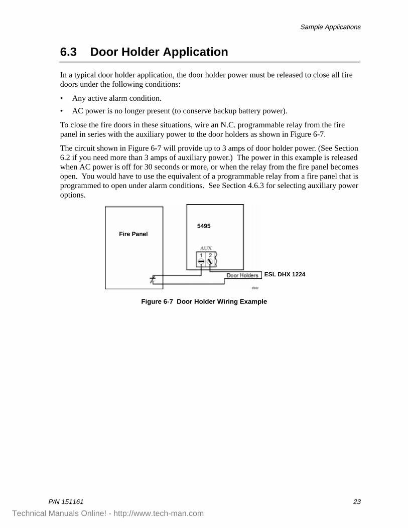
6.3 Door Holder Application
In a typical door holder application, the door holder power must be released to close all fire doors under the following conditions:
• Any active alarm condition.
• AC power is no longer present (to conserve backup battery power).
To close the fire doors in these situations, wire an N.C. programmable relay from the fire panel in series with the auxiliary power to the door holders as shown in Figure 6-7.
The circuit shown in Figure 6-7 will provide up to 3 amps of door holder power. (See Section 6.2 if you need more than 3 amps of auxiliary power.) The power in this example is released when AC power is off for 30 seconds or more, or when the relay from the fire panel becomes open. You would have to use the equivalent of a programmable relay from a fire panel that is programmed to open under alarm conditions. See Section 4.6.3 for selecting auxiliary power options.
Figure 6-7 Door Holder Wiring Example
5495Fire Panel
ESL DHX 1224
Technical Manuals Online! - http://www.tech-man.com
Model 5495 Distributed Power Module Installation Manual
24 P/N 151161
Section 7Troubleshootin g
Light-emitting diodes (LEDs) indicate fault conditions. This section describes the LED states and provides trouble condition details.
7.1 LEDs
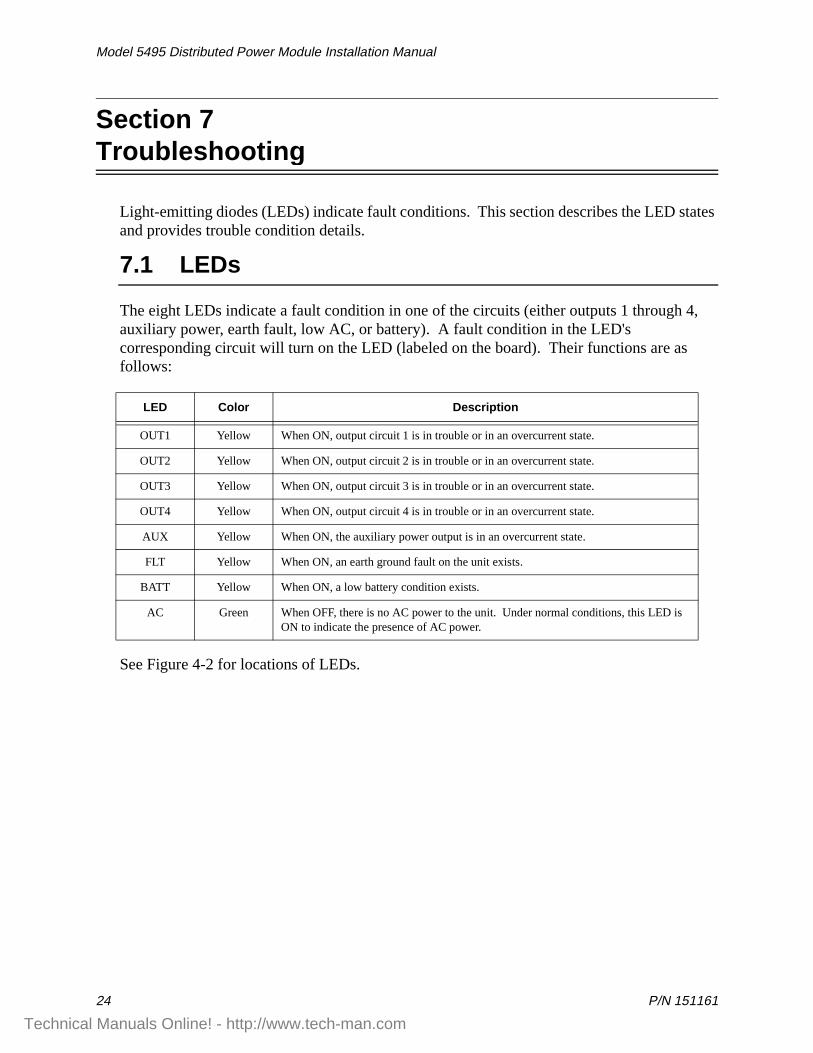
The eight LEDs indicate a fault condition in one of the circuits (either outputs 1 through 4, auxiliary power, earth fault, low AC, or battery). A fault condition in the LED's corresponding circuit will turn on the LED (labeled on the board). Their functions are as follows:
See Figure 4-2 for locations of LEDs.
LED Color Description
OUT1 Yellow When ON, output circuit 1 is in trouble or in an overcurrent state.
OUT2 Yellow When ON, output circuit 2 is in trouble or in an overcurrent state.
OUT3 Yellow When ON, output circuit 3 is in trouble or in an overcurrent state.
OUT4 Yellow When ON, output circuit 4 is in trouble or in an overcurrent state.
AUX Yellow When ON, the auxiliary power output is in an overcurrent state.
FLT Yellow When ON, an earth ground fault on the unit exists.
BATT Yellow When ON, a low battery condition exists.
AC Green When OFF, there is no AC power to the unit. Under normal conditions, this LED is ON to indicate the presence of AC power.
Technical Manuals Online! - http://www.tech-man.com
Troubleshooting
P/N 151161 25
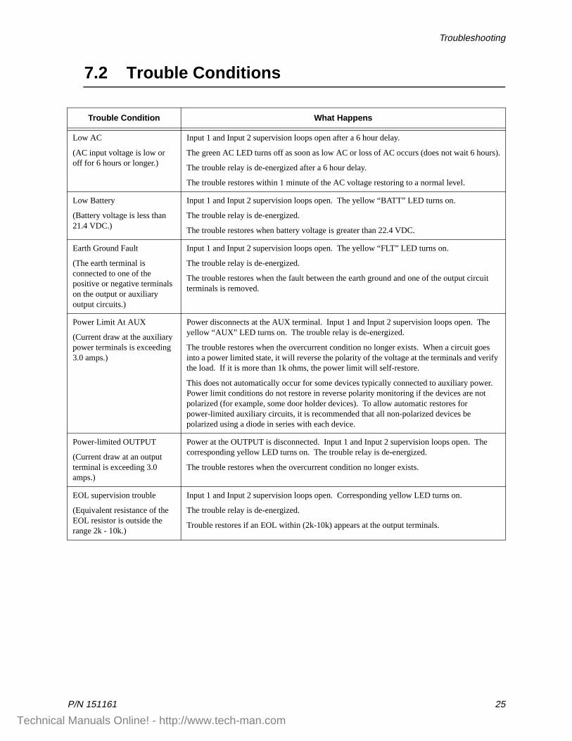
7.2 Trouble Conditions
Trouble Condition What Happens
Low AC
(AC input voltage is low or off for 6 hours or longer.)
Input 1 and Input 2 supervision loops open after a 6 hour delay.
The green AC LED turns off as soon as low AC or loss of AC occurs (does not wait 6 hours).
The trouble relay is de-energized after a 6 hour delay.
The trouble restores within 1 minute of the AC voltage restoring to a normal level.
Low Battery
(Battery voltage is less than 21.4 VDC.)
Input 1 and Input 2 supervision loops open. The yellow “BATT” LED turns on.
The trouble relay is de-energized.
The trouble restores when battery voltage is greater than 22.4 VDC.
Earth Ground Fault
(The earth terminal is connected to one of the positive or negative terminals on the output or auxiliary output circuits.)
Input 1 and Input 2 supervision loops open. The yellow “FLT” LED turns on.
The trouble relay is de-energized.
The trouble restores when the fault between the earth ground and one of the output circuit terminals is removed.
Power Limit At AUX
(Current draw at the auxiliary power terminals is exceeding 3.0 amps.)
Power disconnects at the AUX terminal. Input 1 and Input 2 supervision loops open. The yellow “AUX” LED turns on. The trouble relay is de-energized.
The trouble restores when the overcurrent condition no longer exists. When a circuit goes into a power limited state, it will reverse the polarity of the voltage at the terminals and verify the load. If it is more than 1k ohms, the power limit will self-restore.
This does not automatically occur for some devices typically connected to auxiliary power. Power limit conditions do not restore in reverse polarity monitoring if the devices are not polarized (for example, some door holder devices). To allow automatic restores for power-limited auxiliary circuits, it is recommended that all non-polarized devices be polarized using a diode in series with each device.
Power-limited OUTPUT
(Current draw at an output terminal is exceeding 3.0 amps.)
Power at the OUTPUT is disconnected. Input 1 and Input 2 supervision loops open. The corresponding yellow LED turns on. The trouble relay is de-energized.
The trouble restores when the overcurrent condition no longer exists.
EOL supervision trouble
(Equivalent resistance of the EOL resistor is outside the range 2k - 10k.)
Input 1 and Input 2 supervision loops open. Corresponding yellow LED turns on.
The trouble relay is de-energized.
Trouble restores if an EOL within (2k-10k) appears at the output terminals.
Technical Manuals Online! - http://www.tech-man.com
Model 5495 Distributed Power Module Installation Manual
26 P/N 151161
7.3 Removing and Replacing the Control Panel
This section of the manual provides instruction on how to remove and replace the control panel if it is determined that the control panel needs to be repaired or replaced.
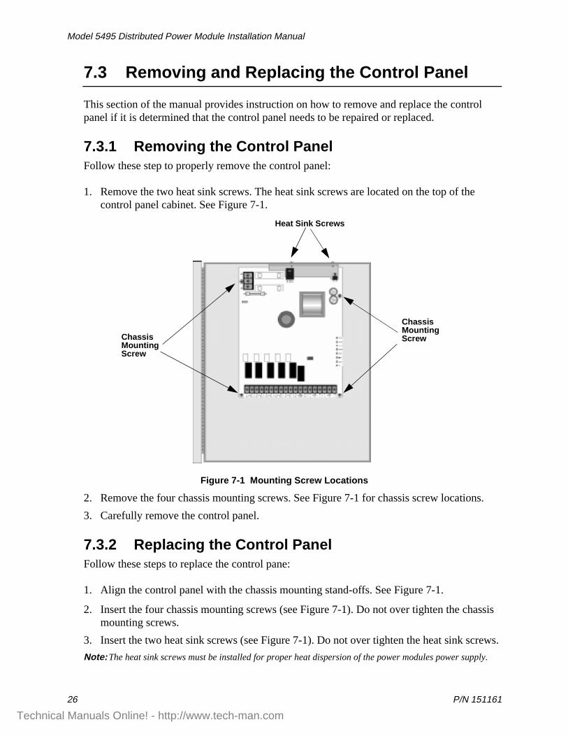
7.3.1 Removing the Control PanelFollow these step to properly remove the control panel:
1. Remove the two heat sink screws. The heat sink screws are located on the top of the control panel cabinet. See Figure 7-1.
Figure 7-1 Mounting Screw Locations
2. Remove the four chassis mounting screws. See Figure 7-1 for chassis screw locations.
3. Carefully remove the control panel.
7.3.2 Replacing the Control PanelFollow these steps to replace the control pane:
1. Align the control panel with the chassis mounting stand-offs. See Figure 7-1.
2. Insert the four chassis mounting screws (see Figure 7-1). Do not over tighten the chassis mounting screws.
3. Insert the two heat sink screws (see Figure 7-1). Do not over tighten the heat sink screws.
Note: The heat sink screws must be installed for proper heat dispersion of the power modules power supply.
Heat Sink Screws
ChassisMountingScrewChassis
MountingScrew
Technical Manuals Online! - http://www.tech-man.com
P/N 151161 33
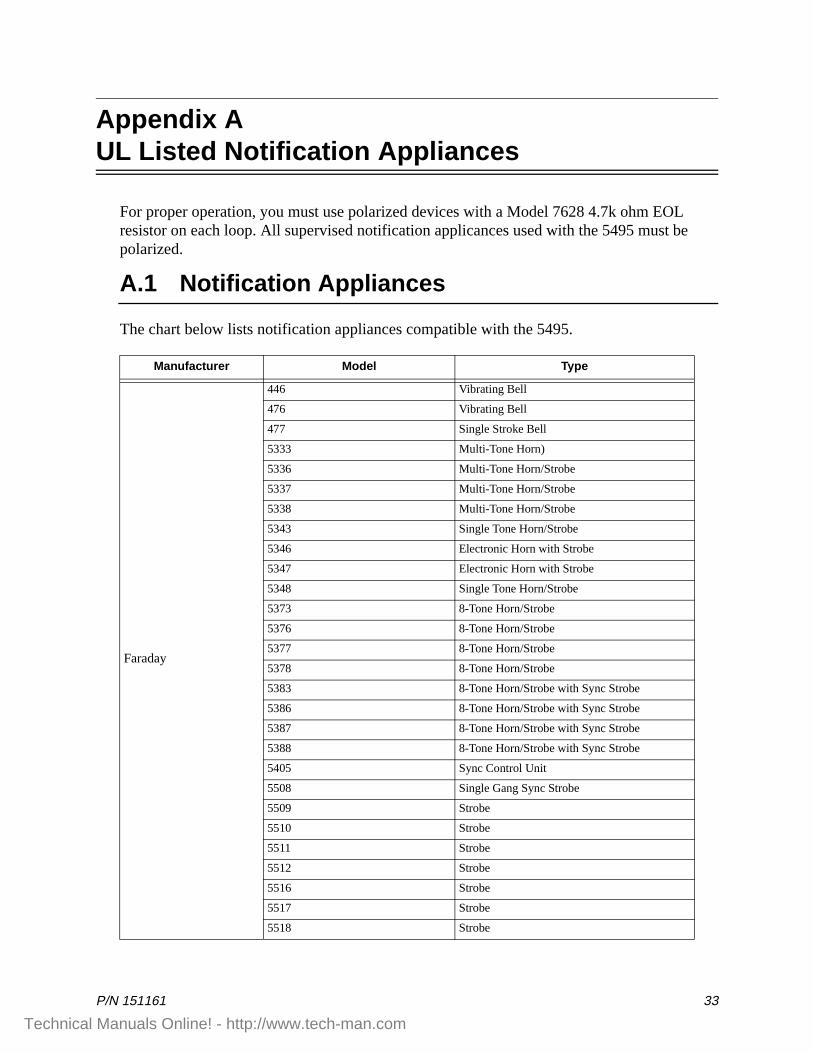
Appendix AUL Listed Notification Appliances
For proper operation, you must use polarized devices with a Model 7628 4.7k ohm EOL resistor on each loop. All supervised notification applicances used with the 5495 must be polarized.
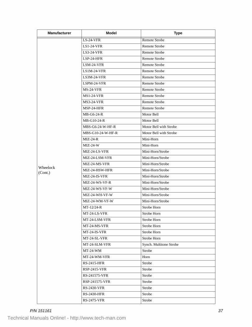
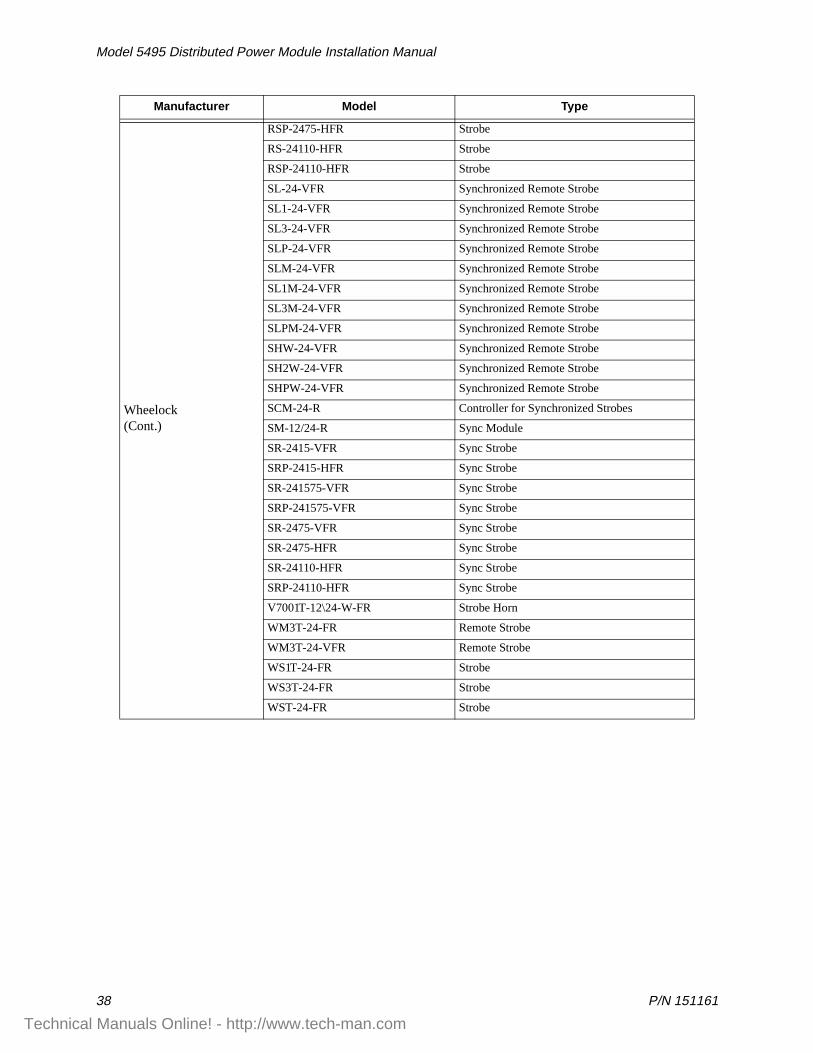
A.1 Notification Appliances
The chart below lists notification appliances compatible with the 5495.
Manufacturer Model Type
Faraday
446 Vibrating Bell
476 Vibrating Bell
477 Single Stroke Bell
5333 Multi-Tone Horn)
5336 Multi-Tone Horn/Strobe
5337 Multi-Tone Horn/Strobe
5338 Multi-Tone Horn/Strobe
5343 Single Tone Horn/Strobe
5346 Electronic Horn with Strobe
5347 Electronic Horn with Strobe
5348 Single Tone Horn/Strobe
5373 8-Tone Horn/Strobe
5376 8-Tone Horn/Strobe
5377 8-Tone Horn/Strobe
5378 8-Tone Horn/Strobe
5383 8-Tone Horn/Strobe with Sync Strobe
5386 8-Tone Horn/Strobe with Sync Strobe
5387 8-Tone Horn/Strobe with Sync Strobe
5388 8-Tone Horn/Strobe with Sync Strobe
5405 Sync Control Unit
5508 Single Gang Sync Strobe
5509 Strobe
5510 Strobe
5511 Strobe
5512 Strobe
5516 Strobe
5517 Strobe
5518 Strobe
Technical Manuals Online! - http://www.tech-man.com
Model 5495 Distributed Power Module Installation Manual
34 P/N 151161
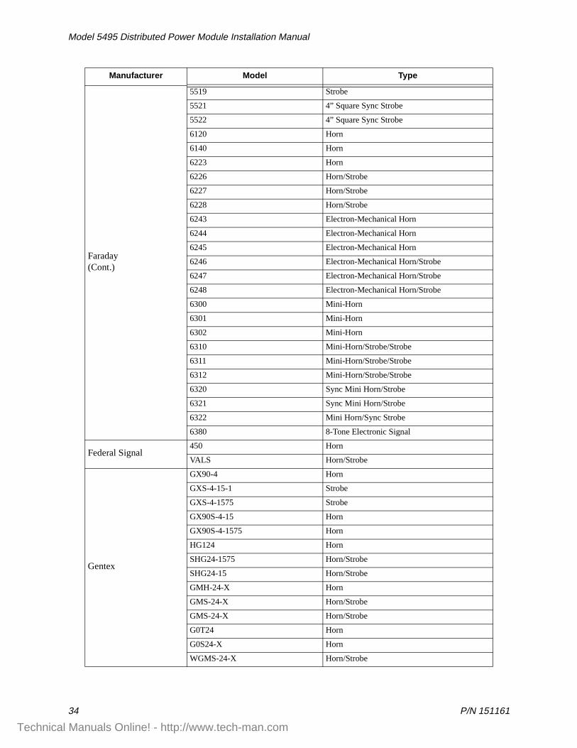
Faraday(Cont.)
5519 Strobe
5521 4” Square Sync Strobe
5522 4” Square Sync Strobe
6120 Horn
6140 Horn
6223 Horn
6226 Horn/Strobe
6227 Horn/Strobe
6228 Horn/Strobe
6243 Electron-Mechanical Horn
6244 Electron-Mechanical Horn
6245 Electron-Mechanical Horn
6246 Electron-Mechanical Horn/Strobe
6247 Electron-Mechanical Horn/Strobe
6248 Electron-Mechanical Horn/Strobe
6300 Mini-Horn
6301 Mini-Horn
6302 Mini-Horn
6310 Mini-Horn/Strobe/Strobe
6311 Mini-Horn/Strobe/Strobe
6312 Mini-Horn/Strobe/Strobe
6320 Sync Mini Horn/Strobe
6321 Sync Mini Horn/Strobe
6322 Mini Horn/Sync Strobe
6380 8-Tone Electronic Signal
Federal Signal450 Horn
VALS Horn/Strobe
Gentex
GX90-4 Horn
GXS-4-15-1 Strobe
GXS-4-1575 Strobe
GX90S-4-15 Horn
GX90S-4-1575 Horn
HG124 Horn
SHG24-1575 Horn/Strobe
SHG24-15 Horn/Strobe
GMH-24-X Horn
GMS-24-X Horn/Strobe
GMS-24-X Horn/Strobe
G0T24 Horn
G0S24-X Horn
WGMS-24-X Horn/Strobe
Manufacturer Model Type
Technical Manuals Online! - http://www.tech-man.com
P/N 151161 35
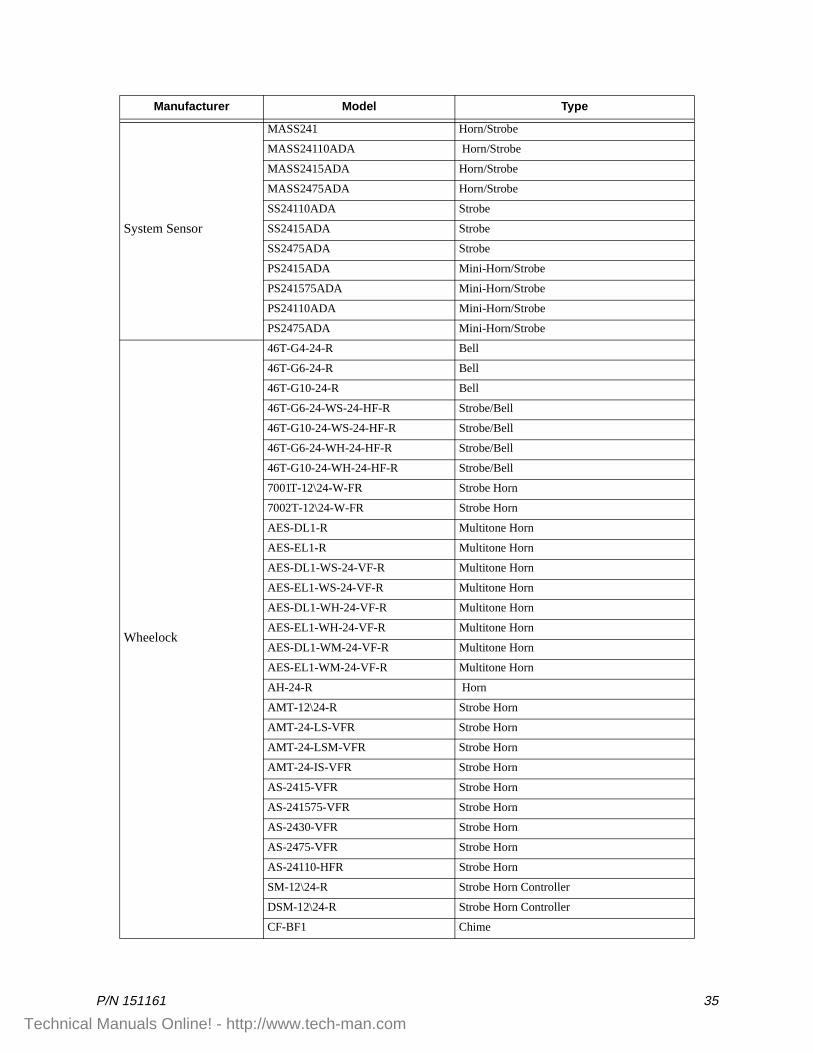
System Sensor
MASS241 Horn/Strobe
MASS24110ADA Horn/Strobe
MASS2415ADA Horn/Strobe
MASS2475ADA Horn/Strobe
SS24110ADA Strobe
SS2415ADA Strobe
SS2475ADA Strobe
PS2415ADA Mini-Horn/Strobe
PS241575ADA Mini-Horn/Strobe
PS24110ADA Mini-Horn/Strobe
PS2475ADA Mini-Horn/Strobe
Wheelock
46T-G4-24-R Bell
46T-G6-24-R Bell
46T-G10-24-R Bell
46T-G6-24-WS-24-HF-R Strobe/Bell
46T-G10-24-WS-24-HF-R Strobe/Bell
46T-G6-24-WH-24-HF-R Strobe/Bell
46T-G10-24-WH-24-HF-R Strobe/Bell
7001T-12\24-W-FR Strobe Horn
7002T-12\24-W-FR Strobe Horn
AES-DL1-R Multitone Horn
AES-EL1-R Multitone Horn
AES-DL1-WS-24-VF-R Multitone Horn
AES-EL1-WS-24-VF-R Multitone Horn
AES-DL1-WH-24-VF-R Multitone Horn
AES-EL1-WH-24-VF-R Multitone Horn
AES-DL1-WM-24-VF-R Multitone Horn
AES-EL1-WM-24-VF-R Multitone Horn
AH-24-R Horn
AMT-12\24-R Strobe Horn
AMT-24-LS-VFR Strobe Horn
AMT-24-LSM-VFR Strobe Horn
AMT-24-IS-VFR Strobe Horn
AS-2415-VFR Strobe Horn
AS-241575-VFR Strobe Horn
AS-2430-VFR Strobe Horn
AS-2475-VFR Strobe Horn
AS-24110-HFR Strobe Horn
SM-12\24-R Strobe Horn Controller
DSM-12\24-R Strobe Horn Controller
CF-BF1 Chime
Manufacturer Model Type
Technical Manuals Online! - http://www.tech-man.com
Model 5495 Distributed Power Module Installation Manual
36 P/N 151161
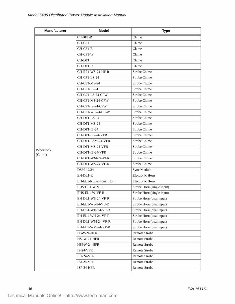
Wheelock(Cont.)
CF-BF1-R Chime
CH-CF1 Chime
CH-CF1-R Chime
CH-CF1-W Chime
CH-DF1 Chime
CH-DF1-R Chime
CH-BF1-WS-24-HF-R Strobe Chime
CH-CF1-LS-24 Strobe Chime
CH-CF1-MS-24 Strobe Chime
CH-CF1-IS-24 Strobe Chime
CH-CF1-LS-24-CFW Strobe Chime
CH-CF1-MS-24-CFW Strobe Chime
CH-CF1-IS-24-CFW Strobe Chime
CH-CF1-WS-24-CF-W Strobe Chime
CH-DF1-LS-24 Strobe Chime
CH-DF1-MS-24 Strobe Chime
CH-DF1-IS-24 Strobe Chime
CH-DF1-LS-24-VFR Strobe Chime
CH-DF1-LSM-24-VFR Strobe Chime
CH-DF1-MS-24-VFR Strobe Chime
CH-DF1-IS-24-VFR Strobe Chime
CH-DF1-WM-24-VFR Strobe Chime
CH-DF1-WS-24-VF-R Strobe Chime
DSM-12/24 Sync Module
EH-DL1-R Electronic Horn
EH-EL1-R Electronic Horn Electronic Horn
EHS-DL1-W-VF-R Strobe Horn (single input)
EHS-EL1-W-VF-R Strobe Horn (single input)
EH-DL1-WS-24-VF-R Strobe Horn (dual input)
EH-EL1-WS-24-VF-R Strobe Horn (dual input)
EH-DL1-WH-24-VF-R Strobe Horn (dual input)
EH-EL1-WH-24-VF-R Strobe Horn (dual input)
EH-DL1-WM-24-VF-R Strobe Horn (dual input)
EH-EL1-WM-24-VF-R Strobe Horn (dual input)
HSW-24-HFR Remote Strobe
HS2W-24-HFR Remote Strobe
HSPW-24-HFR Remote Strobe
IS-24-VFR Remote Strobe
IS1-24-VFR Remote Strobe
IS3-24-VFR Remote Strobe
ISP-24-HFR Remote Strobe
Manufacturer Model Type
Technical Manuals Online! - http://www.tech-man.com
P/N 151161 37
Wheelock(Cont.)
LS-24-VFR Remote Strobe
LS1-24-VFR Remote Strobe
LS3-24-VFR Remote Strobe
LSP-24-HFR Remote Strobe
LSM-24-VFR Remote Strobe
LS1M-24-VFR Remote Strobe
LS3M-24-VFR Remote Strobe
LSPM-24-VFR Remote Strobe
MS-24-VFR Remote Strobe
MS1-24-VFR Remote Strobe
MS3-24-VFR Remote Strobe
MSP-24-HFR Remote Strobe
MB-G6-24-R Motor Bell
MB-G10-24-R Motor Bell
MBS-G6-24-W-HF-R Motor Bell with Strobe
MBS-G10-24-W-HF-R Motor Bell with Strobe
MIZ-24-R Mini-Horn
MIZ-24-W Mini-Horn
MIZ-24-LS-VFR Mini-Horn/Strobe
MIZ-24-LSM-VFR Mini-Horn/Strobe
MIZ-24-MS-VFR Mini-Horn/Strobe
MIZ-24-HSW-HFR Mini-Horn/Strobe
MIZ-24-IS-VFR Mini-Horn/Strobe
MIZ-24-WS-VF-R Mini-Horn/Strobe
MIZ-24-WS-VF-W Mini-Horn/Strobe
MIZ-24-WH-VF-W Mini-Horn/Strobe
MIZ-24-WM-VF-W Mini-Horn/Strobe
MT-12/24-R Strobe Horn
MT-24-LS-VFR Strobe Horn
MT-24-LSM-VFR Strobe Horn
MT-24-MS-VFR Strobe Horn
MT-24-IS-VFR Strobe Horn
MT-24-SL-VFR Strobe Horn
MT-24-SLM-VFR Synch. Multitone Strobe
MT-24-WM Strobe
MT-24-WM-VFR Horn
RS-2415-HFR Strobe
RSP-2415-VFR Strobe
RS-241575-VFR Strobe
RSP-241575-VFR Strobe
RS-2430-VFR Strobe
RS-2430-HFR Strobe
RS-2475-VFR Strobe
Manufacturer Model Type
Technical Manuals Online! - http://www.tech-man.com
Model 5495 Distributed Power Module Installation Manual
38 P/N 151161
Wheelock(Cont.)
RSP-2475-HFR Strobe
RS-24110-HFR Strobe
RSP-24110-HFR Strobe
SL-24-VFR Synchronized Remote Strobe
SL1-24-VFR Synchronized Remote Strobe
SL3-24-VFR Synchronized Remote Strobe
SLP-24-VFR Synchronized Remote Strobe
SLM-24-VFR Synchronized Remote Strobe
SL1M-24-VFR Synchronized Remote Strobe
SL3M-24-VFR Synchronized Remote Strobe
SLPM-24-VFR Synchronized Remote Strobe
SHW-24-VFR Synchronized Remote Strobe
SH2W-24-VFR Synchronized Remote Strobe
SHPW-24-VFR Synchronized Remote Strobe
SCM-24-R Controller for Synchronized Strobes
SM-12/24-R Sync Module
SR-2415-VFR Sync Strobe
SRP-2415-HFR Sync Strobe
SR-241575-VFR Sync Strobe
SRP-241575-VFR Sync Strobe
SR-2475-VFR Sync Strobe
SR-2475-HFR Sync Strobe
SR-24110-HFR Sync Strobe
SRP-24110-HFR Sync Strobe
V7001T-12\24-W-FR Strobe Horn
WM3T-24-FR Remote Strobe
WM3T-24-VFR Remote Strobe
WS1T-24-FR Strobe
WS3T-24-FR Strobe
WST-24-FR Strobe
Manufacturer Model Type
Technical Manuals Online! - http://www.tech-man.com

P/N 151161
Silent Knight Fire Product Warranty and Return Policy
General Terms and Conditions• All new fire products manufactured by Silent Knight after September 1, 1997 have a
limited warranty period of 18 months from the date of manufacture against defects in materials and workmanship. See limited warranty statement for details.
• This limited warranty does not apply to those products that are damaged due to misuse, abuse, negligence, or have been modified in any manner whatsoever.
Repair and RA Procedure• All products that are returned to Silent Knight for credit or repair require a RA (Return
Authorization) number. Call Silent Knight Customer Service at 800-446-6444 or 612-493-6435 between 8:00 A.M. and 5:00 P.M. CST, Monday through Friday to obtain a return authorization number. Silent Knight Technical Support is available at 800-328-0103 between 8:00 A.M. and 6:00 P.M. CST, Monday through Friday.
• RA number must be prominently displayed on the outside of the shipping box. See return address example under Advanced Replacement Policy.
• All products returned to Silent Knight must be sent freight pre-paid. After product is processed, Silent Knight will pay for shipping product back to customer.
• Return the Silent Knight product circuit board only. Products that are returned in cabinets will be charged an additional $20 to cover the extra shipping and handling costs over board only returns. Do not return batteries. Silent Knight has the authority to determine if a product is repairable. Products that are deemed un-repairable will be returned to the customer.
• Product that is returned that has a board date code more than 18 months from date of manufacture will be repaired and the customer will be assessed the standard Silent Knight repair charge for that model.
• A detailed description of the problem should be included with each return.
Advanced Replacement Policy• Silent Knight offers an option of advance replacement for fire product printed circuit
boards that fail during the 18 month warranty period.
• For advance replacement of a defective board call Silent Knight at 800-446-6444 or612-493-6435 to obtain a RA (Return Authorization) number and request advanced replacement.
• Customers must use a MasterCard or Visa credit card to get an advance replacement.
Technical Manuals Online! - http://www.tech-man.com
Model 5495 Distributed Power Module Installation Manual
P/N 151161
• A new or refurbished board will be shipped to the customer. The customer will initially be billed for the replacement board but a credit will be issued after the repairable board is received at Silent Knight.
• The defective board must be returned within 30 days of shipment of replacement board for customer to receive credit. No credit will be issued if the returned board was damaged due to misuse or abuse.
• Repairs and returns should be sent to:
Silent Knight
Attn: Repair Department
7550 Meridian Circle
Maple Grove, MN 55369-4927
RA Number:___________________
Limited WarrantySilent Knight warrants that the products of its manufacture shall be free from defects in materials or workmanship for 18 months from the manufacturing date code on the printed circuit board, if such goods have been properly installed, are subject to normal proper use, and have not been modified in any manner whatsoever. Upon return of the defective product, Silent Knight will at its sole discretion, either repair or replace, at no cost, such goods as may be of defective material or workmanship. Customers outside the United States are to return products to their distributor for repair.
SILENT KNIGHT SHALL NOT UNDER ANY CIRCUMSTANCES BE LIABLE FOR ANY INCIDENTAL OR CONSEQUENTIAL DAMAGES ARISING FROM LOSS OF PROPERTY OR OTHER DAMAGE OR LOSSES OWING TO THE FAILURE OF SILENT KNIGHT SECURITY SYSTEMS PRODUCTS BEYOND THE COST OF REPAIR OR REPLACEMENT OF ANY DEFECTIVE PRODUCTS.
SILENT KNIGHT MAKES NO WARRANTY OF FITNESS OR MERCHANTABILITY AND NO OTHER WARRANTY, ORAL OR WRITTEN, EXPRESS OR IMPLIED, BEYOND THE 18 MONTH WARRANTY EXPRESSLY SPECIFIED HEREIN.
Technical Manuals Online! - http://www.tech-man.com