Embed Size (px)
Citation preview

KME ITALY Handbook of electric cables MIC
1
Fourth issue - 1998
KME ITALY SpA
HANDBOOK OF
ELECTRIC CABLES - MICO

KME ITALY Handbook of electric cables MIC
2

KME ITALY Handbook of electric cables MIC
3
• General introduction pag. 5 FIRST CHAPTER • General characteristics pag. 15 • Correspondence to the manufacturing norms pag. 15 • Dimensional characteristics pag. 16 • Electric characteristics pag. 20 • Insulator characteristics pag. 28 • Temperature limits pag. 29 • Cable behaviour under short circuit condition pag. 30 • Twisted cable pag. 33 • Current capacity pag. 34 SECOND CHAPTER • Introduction pag. 43 • Places with explosion danger pag. 43 • Higher fire risk environments pag. 45 • Electric installations in public entertainment rooms pag. 47 • Fireproof compartments pag. 48 • Other international norms pag. 51 THIRD CHAPTER • Tests pag. 55 • Installation pag. 55 • Large cross-section single-core cables installation pag. 59 • Overvoltages pag. 61 • installation Costs pag. 61 FOURTH CHAPTER • Tests pag. 65 • Cable ends temporary sealing pag. 65 • Terminations pag. 65 • Termination execution pag. 71 • Accessories and tools pag. 79 • Junction boxes pag. 80 • Enclosures pag. 82
INDEX

KME ITALY Handbook of electric cables MIC
4
KME ITALY SpA keeps the right of modifing, any time and without notice, some informations or procedures shown in this handbook.

KME ITALY Handbook of electric cables MIC
5
GENERAL INTRODUCTION
KME ITALY Handbook of electric cables MIC
6
The quality of an electric installation depends on its correspondence to the norms, on technical ability of installer and planner, but also on the behaviour of electrical devices, both in standard and critical conditions. It’s up to norm emitter defining minimum condition under which some devices must work; certification Institutes must verify this conditions to be satisfied during real manufacture; both complex and easy (therefore less critical) structured devices must be subjected to this general rule. MICO cable (Mineral Insulated Cable) belongs to electric cables class, as to say a standard and every-day use product class; on the other hand safety problems hardly concern just electric conduits, because of their characteristic of passing through different environments; so the research of new solutions becomes real significant also in this undervalued field, but vital for the working of a wide range of safety devices that are necessary during particular situations when reliability becomes critical and unreplaceable. In the following section will be made a detailed description of dimensional and electric characteristics of the cable, on the contrary this introduction means to list all general principles that suggest MICO installation. MICO is qualified from Italian norms as FIRE RESISTANT, as to say manufactured in order to pass the test described in CEI 20-36 norm and this fact is verified from IMQ when it certifies the correspondence to CEI 20-39/1 manufacturing norm where tests of CEI 20-36 norm are required. CEI 20-36 norm has been emitted to simulate fire conditions and to prove which cables pass this event. During this test a cable sample lays over a burner and it’s warmed up to 750°C for 3 hours, at one end the cores are separated, at the other they are supplied with rated voltage and protected by 3 A fuses. If no fuse switch off, the cable is “Fire Resistant” qualified. Other countries have harder firetests than this: in U.K. the cable, supplied with rated voltage and protected by 3 A fuses, must be warmed by a flame up to 950°C for 3 hours, then it’s quickly cooled by water spray and, at last, must be mechanically stressed while it’s bended following a “S” shape. This test simulate the action of sprinklers or pumps during a fire and the drop of structures which can hit the cable if it’s laid without protection: when a cable passes this test, it’s qualified CWZ (BS 6387 norm). It’s not up to us to state that this test is much harder than CEI 20-36 norm: during this latter, the cable is supported by 2 metal rings above the burner and it doesn’t move, so even if the insulator carbonizes, it remains between the conductors and keeps the insulation high; during the first one the cable is water sprinkled and beaten by a little metal bar, so insulator cracks and conductors are no longer insulated. MICO cables pass both firetest in CEI 20-36 norm and CWZ test in BS 6387 norm, where temperature goes up to 950°C, simulating temperatur es that can be reached during a fire. On the contrary Australian standard requires the cable to be warmed up to 1050°C inside a furnace and then cooled by water sprinkling; differently from all the others, here the cable must be tested togheter with all fixing systems at sight like channels, clips, clamps: there is the clear willing to test a complete installation system in a real situation and not a series of separate
MICO CABLE: WITH MINERAL INSULATION

KME ITALY Handbook of electric cables MIC
7
devices which could pass the test, if lonely, but could cause some troubles once they are installed. It’s needless to point out that MICO cables pass also this test but it’s important to understand that, though the normative interpretations are different, their aim is the same: defining a representative test simulating fire effects, as realistic as it can, and verifing the effects on complete conduit, more exactly on “At sight Conduit System ”; less critical are the problems related to walled up cables, because in this case fire resistance is given from wall structure and from its REI. Even Firemen had tested MICO cables to verify their structural fire behaviour following the time-temperature curve of circular letter nr. 91 on 14 September 1961. DM 30.11.1983 states that “Fireproof Compartment” is “the building part with predetermined fire resistant building materials as boundaries and organized to answer to fire prevention needs”, so if MICO cables go through a fireproof compartment, they must keep the same characteristics and peculiarities and behave themselves like all the other materials making up fireproof compartment wall. This test has been performed at Research and Test Center of Home Office - Capannelle (Roma),where it’s been declared that our cable behaves itself like a building structural component (REI 90). So we have a great number of examples where MICO cable has been proved in most different and unfavourable conditions, anyway obtaining always good results because of its structure; therefore its performance wouldn’t be discussed but what we’d like to point out is that MICO cable offer a complete and already avalaible solution for any installation requiring at sight layout: in fact we can say that MICO cable is a complet conduit more than a simple electric cable . This statement could seem quite riskly, especially if we think about standard conduit definition: “Group made up by one or more electric conductors and by all the components assuring their insulation, support, fixing and their eventual mechanical protection” (CEI 64-8/2 norm, section 26.1); but, analysing the previous definition, MICO cable, laid at sight with its copper clips, matches all these requires and moreover it’s characterized by a fire resistance which has been verified during many and different conditions. We have noticed that norm Institutes best worry is to make a test to simulate fire conditions the best they can, so to foresee the performance of the cable and to be sure that cables passing this test assure their working also under real condition. Waiting for a different norms agreement to find a compromise between manufacturer and safety needs, a real solution is already avalaible: MICO cable offer absolutely great performances and anticipates future development.
MICO: MINERAL INSULATED CABLE
CopperConductors
Mineral insu lationMgO
Copper sheath Additional LSFcovering
M.I.C. ADVANTAGE

KME ITALY Handbook of electric cables MIC
8
For its exclusive manufacturing method, MICO cable following properties allow this conduit to be a sure and lasting solution and assure unique performances wherever it’s used: • MICO doesn’t deteriorate with age (because insulator doesn’t oxidize); • its current capacity is higher than other cables with equal cross-section (because it doesn’t
stand high temperature); • resists to overload and short circuit current without being damaged (because it doesn’t stand
high temperature); • doesn’t propagate the flame (because it doesn’t burn); • doesn’t propagate the fire(because it doesn’t burn); • doesn’t produce toxic or corroding smokes or gases (because it doesn’t burn); • keep on working during the fire (because it doesn’t burn). Further good qualities due to cable geometry can join to above mentioned thermal nature advantages: • outer sheath acts like protection conductor (therefore this latter is concentric, with all relative
advantages); • concentric protection conductor sorround active conductors avoiding any electric arc outside
the cable, preventing them to be touched or mechanically damaged. Each time a conductor element tries to access the internal part of the cable, this causes a short circuit and the following protection devices switch on. The external sheath of the copper cable and the highly pressed mineral insulator make up a greatly resistant screen towards external mechanical stress.. To assure it, it’s enough to hammer the cable and verify sheath integrity; such mechanical properties make the cable “autonomous” because it can be directly externally laid , with no need of protection tubes. Coaxial configuration of M.I.C. gives another, generally unknown but very important, advantage. In TN systems, as to say the ones supplied with their own transformer room, for an earth damage anywhere in the electric installation, the following condition must be satisfied: U Z IS a0 / > where Uo is a.c. rated voltage (Veff between phase and earth), Ia is the current which makes protection devices switch on within 5 seconds and ZS è is the damage ring impedance (CEI 64-8 norm, art. 413.1.3). Impedance ZS is composed by a resistive and a reactive component: this latter is minimized for coaxial configuration. This means that with MICO is easier to satisfy this condition, especially when the installation is very wide. It’s not enough: during earth damage the voltage on the masses is lower than ordinary cables, because the concentric protection conductor show a lower reactance than phase conductor. At last, we can sum up further advantages of MICO cable this way: • it cannot start a fire or cause indirect contacts (because the conductors are screened from
sorrounding environment by concentric protection conductor); • it doesn’t need protective tube (because its mechanical resistance is similar to a metallic tube
one); • it has minimum damage ring impedance and minimum contact voltage (because it’s a coaxial
cable).

KME ITALY Handbook of electric cables MIC
9
The pleasant aesthetical look is another advantage of M.I.C., that is common to all copper objects. In places where it’s not allowed to break the walls to embed the conduit, for example in monumental buildings, the copper sheath cable is the ideal solution, while a zinc plated steel tube or a metal or PVC channel would be aesthetically unacceptable. It’s interesting to summariza the manufacturing process of MICO cable, to give users the chance to clearly appreciate the properties of its materials, which grant different characteristics from traditional insulation cables. Starting to analyse material components, the starting assembly is made with large diameter, continous and weldless copper tubes, and one or more copper rods; their relative proportion is the same they will have later on, when the cable is finished. Magnesium Oxide powder, after a previous complex treatment, is such compressed to form small cylindrical blocks, with a central lenghtwise hole to allow the right numbers of connectors to be pushed in. This manufacturing method assures a high degree of precision and uniformity of insulator thickness between conductors and between conductors themselves and the outer sheath. After above mentioned components assembly, the tube is drawn, step by step with the necessary intermediate annealing, until we obtain the same cable dimensions imposed by the manufacturing norm. After the coiling of the cables, the last action is an annealing to normalize internal mechanical stresses and to assure the most suitable and uniform handy characteristics.
MANUFACTURING PROCESS

KME ITALY Handbook of electric cables MIC
10

KME ITALY Handbook of electric cables MIC
11
FIRST SECTION
DIMENSIONAL AND ELECTRIC
CHARACTERISTIC

KME ITALY Handbook of electric cables MIC
12
Mineral Insulated Cables are formed by: • outer, continous and weldless sheath, made by a DHP copper tube, with melting point of
1083°C; • Magnesium Oxide insulator, hardly compressed, with melting point of 2800°C; • annealed conductors in ETP 99,9 electrolitic copper wire, with melting point of 1083°C.
CopperConductors
Mineral insu lationMgO
Copper sheath Additional LSFcovering
Power M.I. cables made by E.M. are supplied, on request, with an additional LSF (with polyolefin base) outer covering, conforming to CEI 20-22 standard, with low emission of opaque flue gases and cianoalogenidrici gas according to CEI 20-37 & CEI 20-38 norms (see attached IMQ certificates). The covering can be necessary in one of the following cases: • to garantee protection to the copper sheath in corrosive enviroment; • if copper sheath of the cable is used as PEN conductor; • to make easier the identification of the circuit by the color; • for aestethical reasons (in rooms with particular requirements); • when cables must be laid underground or directly put under plaster.
M.I. Cables made by KME ITALY are in conformity with the following manufacturing norms: • ITALY CEI 20-39/1 - 1995 / IMQ certificate (see enclosed); • U.K. BS 6207 - 1995 / BASEC certificate; • GERMANY DIN VDE 0284-1 - 1995 / VDE certificate. The following tables and the attached IMQ certificates refer to the above mentioned norms that are the national acknowledgements of the harmonized document CENELEC HD 586.1 S1 / 1994; among different type tests, these norms provide for conformity to the CEI 20-36 norm (IEC 331). For this reason M.I.C. is classified “fireproof” Procedures to verify the production quality conform to what it’s required by UNI/EN 29000 & UNI/EN 29002 norms (see attached) For what concerns the essential security requirements, our M.I.C. conforms to the “low voltage” norm Nr. 72/23/EEC modified with Nr. 90/683/EEC. Therefore starting from Jan. 1st 1997, the cables packing has CE mark, as required by the above mentioned norm.
GENERAL CHARACTERISTICS
CORRESPONDENCE TO THE MANUFACTURING NORMS

KME ITALY Handbook of electric cables MIC
13
Nominal diameter over copper sheath
Rated Cross-Section Nominal diameter over copper sheath (mm) ±±±± 0,05 Voltage mm² 1 cond 2 cond 3 cond 4 cond 7 cond 12 cond 19 cond
500 V
1 1,5 2,5 4
5,1 5,7 6,6 7,7
5,8 6,4 7,3
6,3 7,0 8,1
7,6 8,4 9,7
750 V
1,5 2,5 4 6 10 16 25 35 50 70 95
120 150 185 240 300 400
4,9 5,3 5,9 6,4 7,3 8,3 9,6 10,7 12,1 13,7 15,4 16,8 18,4 20,4 23,3 26,0 30,0
7,9 8,7 9,8 10,9 12,7 14,7 17,1
8,3 9,3 10,4 11,5 13,6 15,6 18,2
9,1 10,1 11,4 12,7 14,8 17,3 20,1
10,8 12,1
14,1 15,6
16,6
Nominal conductors diameter
Cross-section (mm²)
1 1,5 2,5 4 6 10 16 25 35
Diameter (mm)
1,13
1,38
1,78
2,26
2,76
3,57
4,51
5,64
6,68
Cross-section
(mm²) 50 70 95 120 150 185 240 300 400
Diameter (mm)
7,98
9,44
11,00
12,36
13,82
15,35
17,48
19,54
22,56
DIMENSIONAL CHARACTERISTICS

KME ITALY Handbook of electric cables MIC
14
Mean copper sheath thickness
Rated Cross-Section Mean copper sheath thickness (mm) - 10% Voltage mm² 1 cond. 2 cond. 3 cond. 4 cond. 7 cond. 12 cond. 19 cond.
500 V
1 1,5 2,5 4
0,41 0,43 0,49 0,54
0,45 0,48 0,50
0,48 0,50 0,54
0,52 0,54 0,61
750 V
1,5 2,5 4 6 10 16 25 35 50 70 95
120 150 185 240 300 400
0,41 0,42 0,45 0,48 0,50 0,54 0,60 0,64 0,69 0,76 0,80 0,85 0,90 0,94 0,99 1,08 1,17
0,54 0,57 0,61 0,65 0,71 0,78 0,85
0,56 0,59 0,63 0,68 0,75 0,82 0,87
0,59 0,62 0,68 0,71 0,78 0,86 0,93
0,65 0,69
0,76 0,81
0,84
Nominal insulation thickness (MgO)
Rated Cross-Section Nominal insulation thickness (mm) -0,1 ÷÷÷÷+20% Voltage mm² 1 cond. 2 cond. 3 cond. 4 cond. 7 cond. 12 cond. 19 cond.
500 V
1 1,5 2,5 4
0,65 0,65 0,65 0,65
0,75 0,75 0,75
0,75 0,75 0,75
0,75 0,75 0,75
750 V
1,5 2,5 4 6
10 16 25 35 50 70 95 120 150 185 240 300 400
1,3 1,3 1,3 1,3 1,3 1,3 1,3 1,3 1,3 1,3 1,3 1,3 1,3 1,4 1,6 1,8 2,1
1,3 1,3 1,3 1,3 1,3 1,3 1,3
1,3 1,3 1,3 1,3 1,3 1,3 1,3
1,3 1,3 1,3 1,3 1,3 1,3 1,3
1,3 1,3
1,3 1,3
1,3

KME ITALY Handbook of electric cables MIC
15
Cable weight without additional covering
Rated Cross-section Cable weight without additional covering (kg/m) Voltage mm² 1 cond 2 cond 3 cond 4 cond 7 cond 12 cond 19 cond
500 V
1 1,5 2,5 4
0,100 0,120 0,176 0,240
0,128 0,158 0,210
0,150 0,190 0,265
0,237 0,285 0,395
750 V
1,5 2,5 4 6 10 16 25 35 50 70 95
120 150 185 240 300 400
0,093 0,113 0,141 0,172 0,235 0,319 0,443 0,573 0,764 1,005 1,270 1,570 1,883 2,315 3,020 3,760 5,006
0,212 0,260 0,342 0,427 0,582 0,845 1,138
0,242 0,311 0,399 0,507 0,728 0,980 1,370
0,298 0,367 0,472 0,623 0,861 1,225 1,752
0,409 0,550
0,685 0,835
0,870
Cable weight with additional LSF covering
Rated Cross-Section Cable weight with additional LSF covering (kg/m)
Voltage mm² 1 cond 2 cond 3 cond 4 cond 7 cond 12 cond 19 cond
500 V
1 1,5 2,5 4
0,121 0,143 0,202 0,274
0,151 0,184 0,243
0,175 0,218 0,301
0,272 0,322 0,437
750 V
1,5 2,5 4 6 10 16 25 35 50 70 95
120 150 185 240 300 400
0,110 0,130 0,164 0,198 0,268 0,356 0,485 0,619 0,816 1,063 1,358 1,668 1,990 2,460 3,186 3,936 5,199
0,243 0,298 0,385 0,474 0,636 0,907 1,238
0,274 0,352 0,444 0,556 0,786 1,069 1,476
0,333 0,411 0,521 0,677 0,923 1,326 1,895
0,455 0,602
0,746 0,927
0,968

KME ITALY Handbook of electric cables MIC
16
Commercial Lenght
Rated Cross-Section Commercial Lenght ±±±± 5% (m) Voltage mm² 1 cond 2 cond 3 cond 4 cond 7 cond 12 cond 19 cond.
500 V
1 1,5 2,5 4
1800♦ 1400♦ 1100♦ 800♦
1500♦ 1100♦ 900♦
1200♦ 900♦ 700♦
800 600 500
750 V
1,5 2,5 4 6 10 16 25 35 50 70 95
120 150 185 240 300 400
1500 1300 1050 1200 950 730 540 440 350 275 215 185 155 125 98 80 80
750 610 480 370 280 205 150
670 520 420 345 245 180 135
560 445 350 270 205 145 110
385 310
210 175
150
♦ For prompt delivery 100 metres coils are ready in warehouse.
Internal coils diameter
Rated Cross-Section Internal coils diameter (mm) Voltage mm² 1 cond 2 cond 3 cond 4 cond 7 cond. 12 cond. 19 cond.
500 V
1 1,5 2,5 4
1150 1150 1150 1150
1150 1150 1150
1150 1150 1150
1150 1150 1150
750 V
1,5 2,5 4 6 10 16 25 35 50 70 95
120 150 185 240 300 400
1150 1150 1150 1150 1150 1150 1150 1450 1450 1450 1450 1450 1450 1450 1450 1450 1450
1150 1150 1150 1450 1450 1450 1450
1150 1150 1450 1450 1450 1450 1450
1150 1450 1450 1450 1450 1450 1450
1450 1450
1450 1450
1450

KME ITALY Handbook of electric cables MIC
17
LSF additional covering thickness
diameter over copper sheath
covering thickness
from to (included) minimum average mm mm mm mm
- 7
15 20
7 15 20 -
0,45 0,54 0,75 0,96
0,65 0,75 1,00 1,25
Nominal conductor resistance
Cross-Section (mm²)
1
1,5
2,5
4
6
10
16
25
35
Nominal resistance at 20 °C
(ohm/km)
17,241
11,494
6,896
4,310
2,835
1,724
1,077
0,690
0,492
Maximum resistance at 20 °C
(ohm/km)
18,100
12,100
7,410
4,610
3,080
1,830
1,150
0,727
0,524
Cross-Section (mm²)
50
70
95
120
150
185
240
300
400
Nominal resistance at 20 °C
(ohm/km)
0,344
0,246
0,181
0,143
0,115
0,093
0,072
0,057
0,043
Maximum resistance at 20 °C
(ohm/km)
0,387
0,268
0,193
0,153
0,124
0,101
0,0775
0,0620
0,046
5
If it is necessary, the electrical conductor resistance value, measured at a temperature different from 20 °C, can be corrected using the following re lation:
Rt L
20254 5
234 51000==== ⋅⋅⋅⋅
++++⋅⋅⋅⋅,
,
dove: t is the cable temperature (°C) during the resistance measurement; R20 is the cable electric resistance at 20 °C (ohm/km); L is the cable length (m); Rt is the cable electric resistance measured at the temperature t
ELECTRICAL CHARACTERISTICS

KME ITALY Handbook of electric cables MIC
18
Nominal copper sheath resistance
Rated Cross-Section Nominal copper sheath resistance (ΩΩΩΩ/km) Voltage mm² 1 cond 2 cond 3 cond 4 cond 7 cond 12 cond 19 cond
500 V
1 1,5 2,5 4
2,855 2,422 1,833 1,419
2,279 1,931 1,614
1,964 1,689 1,344
1,491 1,293 0,990
750 V
1,5 2,5 4 6 10 16 25 35 50 70 95
120 150 185 240 300 400
2,981 2,677 2,238 1,931 1,614 1,310 1,016 0,852 0,697 0,558 0,470 0,405 0,348 0,300 0,248 0,204 0,163
1,381 1,184 0,979 0,824 0,645 0,505 0,397
1,266 1,068 0,892 0,746 0,569 0,453 0,364
1,093 0,934 0,753 0,645 0,502 0,388 0,308
0,832 0,697
0,541 0,458
0,414
Nominal copper sheath cross-section
Rated Cross-Section Nominal copper sheath cross-section (mm²) Voltage mm² 1 cond 2 cond 3 cond 4 cond 7 cond 12 cond 19 cond
500 V
1 1,5 2,5 4
6,04 7,12 9,40
12,14
7,56 8,92
10,68
8,77 10,21 12,82
11,56 13,33 17,42
750 V
1,5 2,5 4 6 10 16 25 35 50 70 95
120 150 185 240 300 400
5,78 6,44 7,70 8,93
10,68 13,16 16,96 20,23 24,73 30,89 36,69 42,59 49,48 57,47 69,39 84,55 105,97
12,49 14,56 17,61 20,93 26,74 34,11 43,39
13,62 16,14 19,34 23,11 30,28 38,07 47,37
15,77 18,46 22,90 26,74 34,36 44,42 56,01
20,73 24,73
31,85 37,64
41,59

KME ITALY Handbook of electric cables MIC
19
Copper sheath maximum resistance
Rated Cross-Section Copper sheath maximum resistance (ΩΩΩΩ/km) Voltage mm² 1 cond 2 cond 3 cond 4 cond. 7 cond. 12 cond. 19 cond.
500 V
1 1,5 2,5 4
3,950 3,350 2,530 1,960
3,150 2,67
2,230
2,710 2,330 1,850
2,060 1,780 1,360
750 V
1,5 2,5 4 6 10 16 25 35 50 70 95
120 150 185 240 300 400
4,130 3,710 3,090 2,670 2,230 1,810 1,400 1,170 0,959 0,767 0,646 0,556 0,479 0,412 0,341 0,280 0,223
1,900 1,630 1,350 1,130 0,887 0,695 0,546
1,750 1,470 1,230 1,030 0,783 0,622 0,500
1,510 1,290 1,040 0,887 0,690 0,533 0,423
1,150 0,959
0,744 0,630
0,570
Copper sheath minimum cross-section
Rated Cross-Section Copper sheath minimum cross-section (mm²) Voltage mm² 1 cond 2 cond. 3 cond 4 cond 7 cond. 12 cond 19 cond.
500 V
1 1,5 2,5 4
4,360 5,140 6,810 8,790
5,470 6,450 7,730
6,360 7,400 9,320
8,370 9,680 12,670
750 V
1,5 2,5 4 6 10 16 25 35 50 70 95
120 150 185 240 300 400
4,170 4,640 5,580 6,450 7,730 9,520 12,320 14,730 17,98 22,48 26,680 31,000 35,990 41,850 50,560 61,570 77,310
9,070 10,580 12,770 15,250 19,430 24,810 31,570
9,850 11,730 14,010 16,740 22,020 27,720 34,480
11,420 13,360 16,570 19,430 24,980 32,340 40,760
14,990 17,980
23,170 27,360
30,240

KME ITALY Handbook of electric cables MIC
20
Light duty multi-core cables (500 V): resistance, r eactance & impedance
cable Resistance R ( ΩΩΩΩ/km) Reactance X Impedance Z ( ΩΩΩΩ/km) type 30 °C 70 °C 105 °C (ΩΩΩΩ/km) 30 °C 70 °C 105 °C 2L1 18,811 21,656 24,145 0,088 18,811 21,656 24,145
2L1,5 12,575 14,477 16,141 0,083 12,576 14,477 16,141 2L2,5 7,701 8,866 9,885 0,079 7,702 8,866 9,885 2L4 4,479 5,157 5,749 0,075 4,480 5,157 5,749 3L1 18,811 21,656 24,145 0,091 18,811 21,656 24,145
3L1,5 12,575 14,477 16,141 0,086 12,576 14,477 16,141 3L2,5 7,701 8,866 9,885 0,079 7,702 8,866 9,885
Above indicated values are valid also for multi-core cables with 4 & 7 conductors
Heavy duty two-core cables (750 V): resistance, rea ctance & impedance
cable Resistance R ( ΩΩΩΩ/km) Reactance X Impedance Z ( ΩΩΩΩ/km) type 30 °C 70 °C 105 °C (ΩΩΩΩ/km) 30 °C 70 °C 105 °C
2H1,5 12,575 14,477 16,141 0,101 12,576 14,478 16,142 2H2,5 7,701 8,886 9,885 0,094 7,702 8,866 9,885 2H4 4,791 5,516 6,150 0,088 4,792 5,516 6,150 2H6 3,200 3,685 4,109 0,083 3,201 3,686 4,110 2H10 1,902 2,190 2,441 0,079 1,904 2,191 2,442 2H16 1,195 1,376 1,534 0,075 1,198 1,378 1,536 2H25 0,756 0,870 0,970 0,073 0,759 0,873 0,973
Above indicated values are valid also for all the other types of multi-core cables (with 3, 4 ,7, 12 & 19 conductors).
Single-core triplet cables: resistance, reactance & impedance
cable type
Resistance R (ΩΩΩΩ/km)
Reactance X (Ω/km)
Impedance Z (ΩΩΩΩ/km)
30 °C 70 °C 105 °C 30 °C 70 °C 105 °C 1H1,5 12,576 14,478 16,142 0,139 12,577 14,478 16,142 1H2,5 7,702 8,866 9,885 0,128 7,703 8,867 9,886 1H4 4,792 5,516 6,15 0,120 4,793 5,518 8,650 1H6 3,202 3,686 4,109 0,112 3,204 3,687 4,111 1H10 1,903 2,190 2,442 0,104 1,906 2,193 2,444 1H16 1,196 1,377 1,535 0,098 1,200 1,380 1,538 1H25 0,757 0,871 0,971 0,093 0,763 0,876 0,975 1H35 0,546 0,628 0,700 0,089 0,554 0,635 0,706 1H50 0,404 0,465 0,518 0,085 0,413 0,473 0,525 1H70 0,281 0,323 0,360 0,083 0,293 0,333 0,369 1H95 0,204 0,234 0,260 0,080 0,219 0,247 0,272
1H120 0,163 0,186 0,207 0,078 0,180 0,202 0,221 1H150 0,133 0,152 0,169 0,077 0,154 0,170 0,185 1H185 0,109 0,123 0,137 0,076 0,133 0,145 0,157 1H240 0,086 0,096 0,106 0,076 0,115 0,123 0,131 1H300 0,076 0,084 0,092 0,075 0,107 0,113 0,119 1H400 0,075 0,063 0,069 0,075 0,095 0,099 0,103
KME ITALY Handbook of electric cables MIC
21
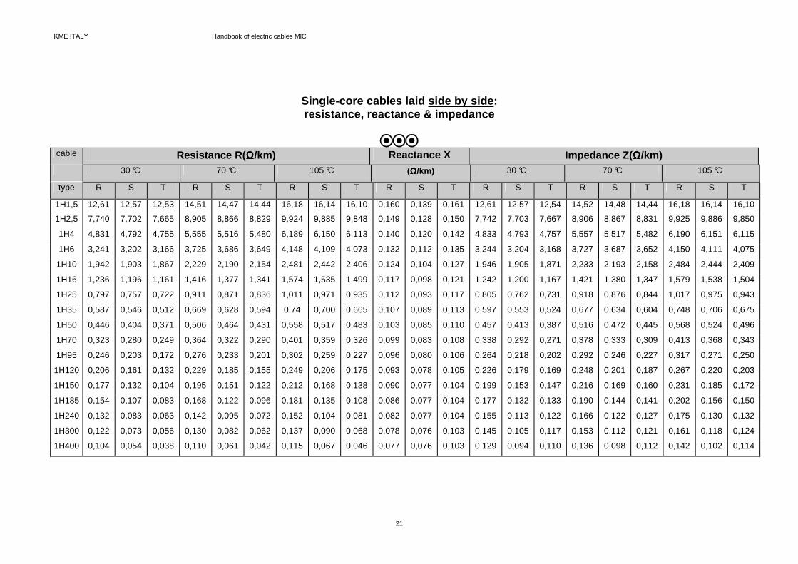
Single-core cables laid side by side : resistance, reactance & impedance
cable Resistance R( ΩΩΩΩ/km) Reactance X Impedance Z( ΩΩΩΩ/km) 30 °C 70 °C 105 °C (ΩΩΩΩ/km) 30 °C 70 °C 105 °C
type R S T R S T R S T R S T R S T R S T R S T
1H1,5 12,61 12,57 12,53 14,51 14,47 14,44 16,18 16,14 16,10 0,160 0,139 0,161 12,61 12,57 12,54 14,52 14,48 14,44 16,18 16,14 16,10
1H2,5 7,740 7,702 7,665 8,905 8,866 8,829 9,924 9,885 9,848 0,149 0,128 0,150 7,742 7,703 7,667 8,906 8,867 8,831 9,925 9,886 9,850
1H4 4,831 4,792 4,755 5,555 5,516 5,480 6,189 6,150 6,113 0,140 0,120 0,142 4,833 4,793 4,757 5,557 5,517 5,482 6,190 6,151 6,115
1H6 3,241 3,202 3,166 3,725 3,686 3,649 4,148 4,109 4,073 0,132 0,112 0,135 3,244 3,204 3,168 3,727 3,687 3,652 4,150 4,111 4,075
1H10 1,942 1,903 1,867 2,229 2,190 2,154 2,481 2,442 2,406 0,124 0,104 0,127 1,946 1,905 1,871 2,233 2,193 2,158 2,484 2,444 2,409
1H16 1,236 1,196 1,161 1,416 1,377 1,341 1,574 1,535 1,499 0,117 0,098 0,121 1,242 1,200 1,167 1,421 1,380 1,347 1,579 1,538 1,504
1H25 0,797 0,757 0,722 0,911 0,871 0,836 1,011 0,971 0,935 0,112 0,093 0,117 0,805 0,762 0,731 0,918 0,876 0,844 1,017 0,975 0,943
1H35 0,587 0,546 0,512 0,669 0,628 0,594 0,74 0,700 0,665 0,107 0,089 0,113 0,597 0,553 0,524 0,677 0,634 0,604 0,748 0,706 0,675
1H50 0,446 0,404 0,371 0,506 0,464 0,431 0,558 0,517 0,483 0,103 0,085 0,110 0,457 0,413 0,387 0,516 0,472 0,445 0,568 0,524 0,496
1H70 0,323 0,280 0,249 0,364 0,322 0,290 0,401 0,359 0,326 0,099 0,083 0,108 0,338 0,292 0,271 0,378 0,333 0,309 0,413 0,368 0,343
1H95 0,246 0,203 0,172 0,276 0,233 0,201 0,302 0,259 0,227 0,096 0,080 0,106 0,264 0,218 0,202 0,292 0,246 0,227 0,317 0,271 0,250
1H120 0,206 0,161 0,132 0,229 0,185 0,155 0,249 0,206 0,175 0,093 0,078 0,105 0,226 0,179 0,169 0,248 0,201 0,187 0,267 0,220 0,203
1H150 0,177 0,132 0,104 0,195 0,151 0,122 0,212 0,168 0,138 0,090 0,077 0,104 0,199 0,153 0,147 0,216 0,169 0,160 0,231 0,185 0,172
1H185 0,154 0,107 0,083 0,168 0,122 0,096 0,181 0,135 0,108 0,086 0,077 0,104 0,177 0,132 0,133 0,190 0,144 0,141 0,202 0,156 0,150
1H240 0,132 0,083 0,063 0,142 0,095 0,072 0,152 0,104 0,081 0,082 0,077 0,104 0,155 0,113 0,122 0,166 0,122 0,127 0,175 0,130 0,132
1H300 0,122 0,073 0,056 0,130 0,082 0,062 0,137 0,090 0,068 0,078 0,076 0,103 0,145 0,105 0,117 0,153 0,112 0,121 0,161 0,118 0,124
1H400 0,104 0,054 0,038 0,110 0,061 0,042 0,115 0,067 0,046 0,077 0,076 0,103 0,129 0,094 0,110 0,136 0,098 0,112 0,142 0,102 0,114

KME ITALY Handbook of electric cables MIC
22
Single-core cables laid at the distance of a diamet er: resistance, reactance & impedance
cable Resistance R (Ω/km) Reactance X Impedance Z( ΩΩΩΩ/km) 30 °C 70 °C 105 °C (ΩΩΩΩ/km) 30 °C 70 °C 105 °C
type R S T R S T R S T R S T R S T R S T R S T 1H1,5 12,61 12,57 12,54 14,52 14,48 14,44 16,18 16,14 16,10 0,203 0,182 0,205 12,61 12,57 12,54 14,52 14,48 14,44 16,18 16,14 16,10
1H2,5 7,743 7,703 7,767 8,907 8,867 8,831 9,925 9,886 9,850 0,192 0,171 0,194 7,745 7,705 7,670 8,907 8,867 8,831 9,927 9,888 9,852
1H4 4,833 4,793 4,728 5,557 5,518 5,482 6,191 6,151 6,115 0,183 0,163 0,186 4,837 4,796 4,762 5,560 5,520 5,485 6,194 6,154 6,118
1H6 3,244 3,203 3,169 3,727 3,687 3,652 4,150 4,111 4,075 0,175 0,156 0,179 3,248 3,207 3,174 3,731 3,691 3,656 4,154 4,114 4,079
1H10 1,946 1,905 1,870 2,232 2,192 2,157 2,484 2,443 2,408 0,167 0,148 0,171 1,953 1,911 1,878 2,239 2,197 2,164 2,489 2,448 2,414
1H16 1,24 1,199 1,165 1,420 1,379 1,345 1,578 1,537 1,502 0,160 0,141 0,165 1,250 1,207 1,177 1,429 1,386 1,355 1,586 1,543 1,511
1H25 0,803 0,760 0,728 0,916 0,874 0,841 1,015 0,973 0,940 0,154 0,136 0,161 0,817 0,772 0,746 0,928 0,884 0,856 1,026 0,983 0,954
1H35 0,593 0,550 0,519 0,674 0,632 0,600 0,745 0,703 0,671 0,150 0,132 0,157 0,611 0,566 0,543 0,690 0,645 0,620 0,760 0,716 0,689
1H50 0,453 0,409 0,379 0,512 0,469 0,438 0,564 0,521 0,490 0,145 0,129 0,154 0,475 0,429 0,410 0,532 0,486 0,465 0,583 0,537 0,514
1H70 0,332 0,287 0,259 0,372 0,328 0,299 0,408 0,364 0,334 0,140 0,126 0,152 0,360 0,313 0,301 0,398 0,351 0,336 0,431 0,385 0,367
1H95 0,257 0,210 0,185 0,285 0,239 0,212 0,310 0,265 0,237 0,136 0,123 0,150 0,289 0,244 0,239 0,315 0,269 0,260 0,339 0,292 0,281
1H120 0,217 0,170 0,147 0,239 0,193 0,168 0,259 0,213 0,186 0,133 0,121 0,149 0,253 0,209 0,209 0,273 0,228 0,224 0,291 0,245 0,238
1H150 0,190 0,142 0,121 0,207 0,160 0,137 0,222 0,176 0,151 0,129 0,120 0,147 0,227 0,185 0,190 0,243 0,199 0,201 0,257 0,213 0,211
1H185 0,169 0,120 0,105 0,182 0,134 0,116 0,194 0,146 0,126 0,123 0,199 0,147 0,205 0,168 0,179 0,218 0,178 0,187 0,194 0,146 0,126
1H240 0,148 0,100 0,141 0,158 0,110 0,097 0,167 0,118 0,103 0,116 0,117 0,145 0,183 0,153 0,168 0,194 0,160 0,173 0,203 0,166 0,178
1H300 0,139 0,093 0,085 0,147 0,099 0,088 0,154 0,105 0,092 0,112 0,115 0,143 0,172 0,146 0,162 0,182 0,151 0,166 0,190 0,156 0,170
1H400 0,120 0,075 0,069 0,126 0,079 0,071 0,131 0,83 0,073 0,108 0,115 0,142 0,155 0,135 0,152 0,163 0,139 0,160 0,170 0,142 0,159
KME ITALY Handbook of electric cables MIC
23
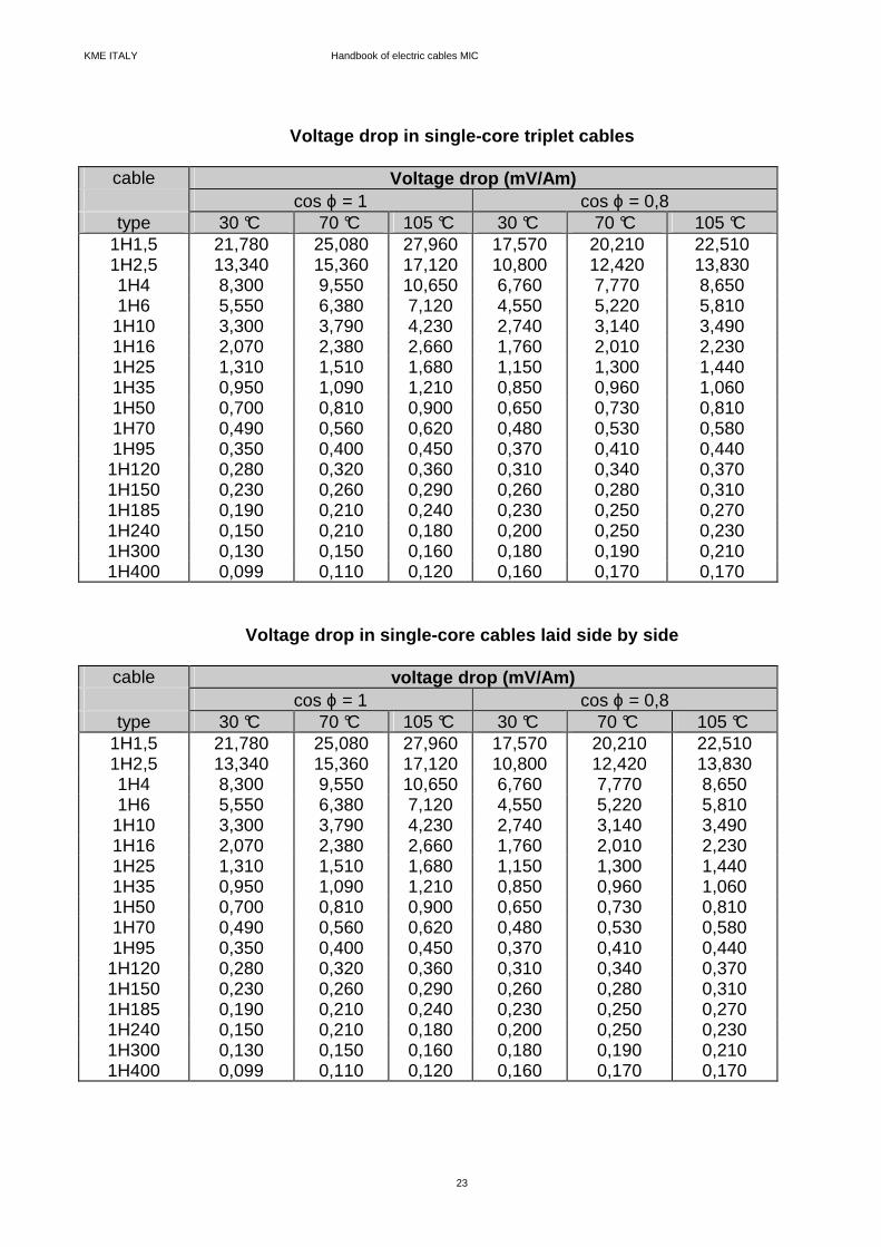
Voltage drop in single-core triplet cables
cable Voltage drop (mV/Am) cos ϕ = 1 cos ϕ = 0,8
type 30 °C 70 °C 105 °C 30 °C 70 °C 105 °C 1H1,5 21,780 25,080 27,960 17,570 20,210 22,510 1H2,5 13,340 15,360 17,120 10,800 12,420 13,830 1H4 8,300 9,550 10,650 6,760 7,770 8,650 1H6 5,550 6,380 7,120 4,550 5,220 5,810
1H10 3,300 3,790 4,230 2,740 3,140 3,490 1H16 2,070 2,380 2,660 1,760 2,010 2,230 1H25 1,310 1,510 1,680 1,150 1,300 1,440 1H35 0,950 1,090 1,210 0,850 0,960 1,060 1H50 0,700 0,810 0,900 0,650 0,730 0,810 1H70 0,490 0,560 0,620 0,480 0,530 0,580 1H95 0,350 0,400 0,450 0,370 0,410 0,440
1H120 0,280 0,320 0,360 0,310 0,340 0,370 1H150 0,230 0,260 0,290 0,260 0,280 0,310 1H185 0,190 0,210 0,240 0,230 0,250 0,270 1H240 0,150 0,210 0,180 0,200 0,250 0,230 1H300 0,130 0,150 0,160 0,180 0,190 0,210 1H400 0,099 0,110 0,120 0,160 0,170 0,170
Voltage drop in single-core cables laid side by sid e
cable voltage drop (mV/Am) cos ϕ = 1 cos ϕ = 0,8
type 30 °C 70 °C 105 °C 30 °C 70 °C 105 °C 1H1,5 21,780 25,080 27,960 17,570 20,210 22,510 1H2,5 13,340 15,360 17,120 10,800 12,420 13,830 1H4 8,300 9,550 10,650 6,760 7,770 8,650 1H6 5,550 6,380 7,120 4,550 5,220 5,810
1H10 3,300 3,790 4,230 2,740 3,140 3,490 1H16 2,070 2,380 2,660 1,760 2,010 2,230 1H25 1,310 1,510 1,680 1,150 1,300 1,440 1H35 0,950 1,090 1,210 0,850 0,960 1,060 1H50 0,700 0,810 0,900 0,650 0,730 0,810 1H70 0,490 0,560 0,620 0,480 0,530 0,580 1H95 0,350 0,400 0,450 0,370 0,410 0,440
1H120 0,280 0,320 0,360 0,310 0,340 0,370 1H150 0,230 0,260 0,290 0,260 0,280 0,310 1H185 0,190 0,210 0,240 0,230 0,250 0,270 1H240 0,150 0,210 0,180 0,200 0,250 0,230 1H300 0,130 0,150 0,160 0,180 0,190 0,210 1H400 0,099 0,110 0,120 0,160 0,170 0,170

KME ITALY Handbook of electric cables MIC
24
Voltage drop in single-core cables laid at the dist ance of a diameter
cable Voltage drop (mV/Am) cos ϕ = 1 cos ϕ = 0,8
type 30 °C 70 °C 105 °C 30 °C 70 °C 105 °C 1H1,5 21,790 25,080 27,960 17,630 20,270 22,570 1H2,5 13,340 15,360 17,130 10,870 12,480 13,890 1H4 8,300 9,560 10,660 6,830 7,830 8,710 1H6 5,550 6,390 7,120 4,620 5,290 5,870
1H10 3,300 3,800 4,240 2,810 3,210 3,560 1H16 2,060 2,390 2,670 1,830 2,080 2,290 1H25 1,320 1,520 1,690 1,210 1,370 1,510 1H35 0,960 1,100 1,220 0,920 1,030 1,130 1H50 0,720 0,820 0,910 0,720 0,800 0,880 1H70 0,510 0,580 0,640 0,550 0,610 0,660 1H95 0,380 0,430 0,470 0,440 0,480 0,520
1H120 0,310 0,350 0,380 0,380 0,420 0,440 1H150 0,260 0,290 0,320 0,340 0,370 0,390 1H185 0,230 0,250 0,270 0,310 0,330 0,350 1H240 0,200 0,210 0,220 0,280 0,300 0,310 1H300 0,180 0,190 0,200 0,270 0,280 0,290 1H400 0,150 0,160 0,170 0,240 0,250 0,260
Voltage drop in Light duty multi-core cables (500 V )
cable Voltage drop (mV/Am) cos ϕ = 1 cos ϕ = 0,8
type 30 °C 70 °C 105 °C 30 °C 70 °C 105 °C 2L1 37,620 43,310 48,290 30,200 34,760 38,740
2L1,5 25,150 28,950 32,280 20,220 23,260 25,930 2L2,5 15,400 17,730 19,770 12,420 14,280 15,910 2L4 8,960 10,310 11,500 7,260 8,340 9,290 3L1 32,580 37,51 41,820 26,160 30,100 33,550
3L1,5 21,780 25,080 27,960 17,510 20,150 22,460 3L2,5 13,340 15,360 17,120 10,750 12,370 13,780
Above indicated values are valid also for multi-core cables with 4 & 7 conductors.
Voltage drop in Heavy duty multi-core cables (750 V )
cable Voltage drop (mV/Am) cos ϕ = 1 cos ϕ = 0,8
type 30 °C 70 °C 105 °C 30 °C 70 °C 105 °C 2H1,5 25,150 28,950 32,280 20,240 23,280 25,950 2H2,5 15,400 17,730 19,770 12,430 14,300 15,930 2H4 9,580 11,030 12,300 7,770 8,930 9,940 2H6 6,401 7,370 8,220 5,220 6,000 6,670
2H10 3,800 4,380 4,880 3,140 3,600 4,000 2H16 2,390 2,750 3,070 2,000 2,290 2,540 2H25 1,510 1,740 1,940 1,300 1,480 1,640
Above indicated values are valid also for all the other types of multi-core cables (with 3, 4 ,7, 12 & 19 conductors).

KME ITALY Handbook of electric cables MIC
25
Thermal conductivity
As we know, an electric insulator is a thermal insulator too; so in ordinary cables the electric insulator interferes with heat diffusion outwards and, therefore, under the same current flow, the temperature of a standard cable is higher than a M.I.C. In fact, Magnesium Oxide is an exception to this general rule: it’s an excellent electric insulator and a good thermal conductor; these 2 characteristics allow MgO to insulate the conductors and to easily transmit outwards the heat produced by Joule effect. Thermal conductivity of Magnesium Oxide increases with its density, resulting from compression ratio; the KME ITALY manufacturing process gives a density of 2,0 g/cm3 to which corrisponds a thermal conductivity of 2,36 w/m °C.
DIELECTRIC STRENGTH
Insulator dielectric strength decreases with temperature increase, as shown in the following diagram; we can quite ignore this decrease at temperatures lower than 1000 °C.
°C
Vmm
400 600 800 1000 12001000
2000
3000
4000
RESISTANCE TO HUMIDITY Magnesium Oxide, used in M.I.C. as electric insulator, is hygroscopic, so enviroment humidity decreases its insulation resistance; the latter, measured by a Megaohmeter at 500 V, must be more than 100 MΩ. Anyway, if a cable end is open, humidity goes inside only for few centimetres; the following diagram shows the depth of humidity penetration in relation to the time of exposure of a cable with unsealed ends.
months
cm
25
20
15
10
5
0 1 2 3 4 5 6 Therefore humidity can easily be removed cutting approx. 100 mm of cable from both ends without heating, or heating the cable in order to push humidity itself towards the open ends. To avoid humidity absorption, all cable coils are temporarily sealed both on factory exit and during the storing; every cable used in an electric wiring system must be protected by suitable terminations.
INSULATION CHARACTERISTICS

KME ITALY Handbook of electric cables MIC
26
Magnesium Oxide insulation is stable and it doesn’t suffer any agening as temperature grows up to the melting point of 2800°C; so the theoretic al temperature limit of M.I.C. is determined by the copper melting point (external sheath and conductors): 1083 °C. Up to this temperature cables are totally inert to flame and they don’t produce any kind of toxic, corrosive or opaque flue gas; hardly temperature during a fire goes over 1000°C. But it would be better not to use M.I.C. where temperature, in continous exercise, goes over 250 °C. In fact, over this temperature, the external oxidation of the copper sheath is so fast to decrease its thickness in a short time; the following table shows the theoretical reduction of the sheath thickness in relation to both time and temperature.
Sheath thickness
250 °C 400 °C 800 °C
reduction ( µµµµ m) years years hours 25,4 50,8
127,0 254,0
2,57 10,30 64,30
257,00
0,0583 0,2330 1,4600 5,8300
0,259 1,040 6,480
25,900
In relation to the above mentioned values we can approx. obtain the time in which the copper sheath thickness assumes a lower value than 10% in comparison with its nominal value In short circuit condition the electric cables can suffer mechanical damages (due to electrodynamic forces developing between conductors) and thermal damages (extreme heating); the electrodynamic forces created by a short circuit don’t damage multi-core cables, which are structurally quite strong; on the contrary single-core cables laid side by side on platform can suffer violent shifting and they can cause or suffer damages. In this case, it’s a good habit to fix the cables to their support by brackets at short distance (about 1 m). An electric conductor must resist also thermal troubles; its dimension (section) must be choosen so as a short circuit current “I” can flow through the cable for a time “t”, less than 5 seconds, in which automatic protection devices must switch on and temperature must not go over a fixed limit (CEI 64-8/434.3.2); this current value can be determined by the following formula:
I S Kt
==== ⋅⋅⋅⋅ ⋅⋅⋅⋅1
where: S = conductor cross-section (mm²); K = factor whose value depends on the material of the protection conductor, of the
insulator and other parts and on starting and final temperature; this factor is calculated by the following formula (CEI 64-8 appendix B, chapter 54):
(((( ))))K
Qc BLn
fB
====⋅⋅⋅⋅ ++++
⋅⋅⋅⋅ ++++ −−−−++++
20
201
00ρρρρ
θθθθ θθθθθθθθ
where:
TEMPERATURE LIMITS
M.I.C. BEHAVIOUR IN SHORT CIRCUIT CONDITION

KME ITALY Handbook of electric cables MIC
27
Qc = thermal capacity per volume unit of the conductor (J/°C mm 3) B = inverse of temperature coefficient of resistivity at 0°C for the conductor(°C); ρρρρ20 = conductive material resistivity at 20 °C; θθθθ o = conductor starting temperature (°C); θθθθ f = conductor final temperature(°C). B, Qc e ρρρρ20 values can be derived from the following table:
material B Qc ρρρρ20
Copper 235 3,45 * 10 -3 17,241 * 10 -6 Alluminium 228 2,50 * 10 -3 28,264 * 10 -6
Lead 230 1,45 * 10 -3 214,000 * 10 -6 Steel 202 3,80 * 10 -3 138,000 * 10 -6
CEI 64-8 norm art. 434.3.2 provides for copper conductors the following values of “K” with relative values of maximum temperatures allowed during ordinary working and during short circuit in relation to the insulator peculiarity:
Conductor type
K Ordinary
working (°C) short circuit
(°C) PVC insulated copper conductors 115 70 160 within reach & LSF external sheath MIC 115 70 160 standard plastic insulated copper conductors 135 60 200 butyl rubber insulated copper conductors 135 85 220 within reach & bare MIC 135 70 200 EPR and XLPE insulated copper conductors 143 90 250 out of reach & bare MIC 200 105 500 Therefore cable minimum cross-section value, in relation to the short circuit current and to the switch time of protection devices, can be evalueted by the following formula:
SI t
K==== ⋅⋅⋅⋅
The following tables show the value of minimum section to be used with a bare & within reach M.I.C. and the correspondent value of section for other types of cable, in relation to 2 diferent switching times of protection devices.
Short circuit period = 0,01 s
insulator Minimum cross-section (mm²) for a short circuit current (kA)
corresponding to 5 10 15 25 35
Mineral (k=200) EPR (k=143) butyl rubber (k=135) PVC (k=115)
2,5 4 4 6
6 10 10 10
10 16 16 16
16 25 25 25
25 25 35 35

KME ITALY Handbook of electric cables MIC
28
Short circuit period = 1 s
insulator Minimum cross-section (mm²) for a short circuit current (kA)
corresponding to 5 10 15 25 35
Mineral (k=200) EPR (k=143) butyl rubber (k=135) PVC (k=115)
25 35 50 50
50 70 95 95
95 120 120 150
150 185 185 240
185 300 300 400
The tables show how M.I.C. allows, in relation to thermal stress due to short circuit, to use conductors with considerably lower cross-section than all the other ; the following diagram let us fastly calculate the minimum cable cross-section, according to short circuit current value and its duration.
400
300240
185150120 9570
50
35
25
16
10
time (s)10,50,10,050,01
800572540480
57 67 71 100
10
1
5,8 6,8 7,2
kA kA kA kA(1) (2) (3) (4)
mm2
"
"
"
"
"
"
"
"
"
"
"
"
(1) k = 115 for PVC insulated copper conductors & for M.I.C. with LSF outer covering; (2) k = 135 for ordinary or butyl rubber insulated copper conductors & bare and within
reach M.I.C.; (3) k = 143 for ethylene - propylene or reticulated propylene rubber insulated copper
conductors; (4) k = 200 for bare and out of reach M.I.C.
With the same manufacturing technology process it’s possible to supply a “twisted” Light duty M.I.C. (300/500), type 2T1,5 with additional LSF outer covering, red-coloured with low emission of opaque flue gas (CEI 20-37 e CEI 20-38).
“TWISTED” MINERAL INSULATED CABLES

KME ITALY Handbook of electric cables MIC
29
CopperConductors
Mineral InsulationMgO
Copper Sheath(PE)
Additional Coveringin LSF
The above cable is manufactured and tested in conformity with CEI 20-39/1 and can be sealed and installed like all the other M.I.C.; in fact its dimensional and electric characteristics, its terminations and fittings are the same indicated in previous pages for cable type 2L1,5. Further characteristics are:
Nominal capacity between conductors at 1 kHz 164,5 pF/m Nominal capacity between a conductor and copper screen at 1 kHz 243, 5 pF/m Nominal capacity between 2 conductors and copper screen at 1 kHz 384,4 pF/m Inductance (loop) at 10 MHz 436,0 µH/m Attenuation at 1 MHz - 19,0 dB/km Attenuation at 10 MHz - 52,0 dB/km Nominal characteristic impedance 50 Ω Twist frequency per metre 20
For what we stated above and because of its copper sheath, which is an excellent electrostatic screen at low impedance, the twisted M.I.C. notably reduces electromagnetic interferences and signal noises in modern integrated management systems of security.
External magnetic fields Electrostatics Discharge such as: • fire alarms systems; • security phone systems; • data transmission systems; • etc. .... As all the other M.I.C., the twisted cable has the peculiarity of keeping working even in critical enviroment conditions, such as fire with mechanical stress and water sprinkling. Red coloured 2T1,5/LSF cable can be supplyed in standard coils of 100 metres or multiple of length. On request also 2T1/LSF type of cable is avalaible.
M.I.C. capacity values are indicated in CEI -UNEL 35024/2-1997 norm, based on CENELEC R064001(1991) Report; This norm must be applied to fixed electric installations whose main characteristics are described in CEI 64-8 norm, part 5.
CURRENT CAPACITY

KME ITALY Handbook of electric cables MIC
30
The Iz (A) M.I.C. capacity, in a particular condition of installation, can be deduced from the following formula:
Iz = I0 x k1 x k2 where: I0 = capacity in air at 30 °C related to preseen insta llation method, deduced from tables I & II; k1 = correction factor for room temperature different from 30 °C (table III); k2 = correction factor for many bundled layered circuits (tables IV - V or VI). bundle and layer definitions are: Layer : group of circuits made with cables laid side by side, spaced or not, put in horizontal or
vertical position; layered cables are installed on wall, platform, ceiling, floor or ladder tray. NOTES - many layers one upon the others on the same support (for example a platform) are to be
considered a bundle; - 2 single-core cables, belonging to different circuits, are spaced when their distance is more than 2 times the outer diameter of the bigger cross-section cable;
- 2 multi-core cables are spaced when their distance is more than the outer diameter.
Bundle : group of many circuits made with not spaced and not layered cables. NOTE - We specify that the maximum temperature mentioned in the respective tables refers to metal
sheath and not to conductors: in particular installations, cables thermal computation can be made using method reported in CEI 20-21 norm, presuming conductors and metal sheath to be at the same temperature.
The number of conductors to be considered is the number of conductors where really current flows. For capacity computation, three-phase system is supposed to be balanced. Table 1 and 2 capacities are defined for maximum working temperature, indicated below each table. Capacity values are based on a room temperature of 30°C. For different ones, these values must be multiplied by the proper correction factors, that can be deduced from table III. When many circuits are installed in the same bundle and they are put in one or more horizontal or vertical spaced layer, capacity must be multiplied by the proper correction factors shown in tables IV - V or VI of CEI UNEL 35024/2-1997 norm. When two or more conductors are connected in parallel in the same system phase or pole, it’s necessary to take particular precautions in order to assure current to be equally divided between them; these precautions are respected if: a - conductors have the same cross-section; b - conductors have approx. the same length and they are not shunted to other circuits; c - all conductors in parallel belong to single-core or multi-core cables transposed along the
course.

KME ITALY Handbook of electric cables MIC
31
For single - core not transposed cables, triplet or laid, with conductors of section > 50 mm², it’s necessary to take particular installation precautions for what concerns phases spacing and their best sequence.

KME ITALY Handbook of electric cables MIC
32
Table I/1 single-core H (750 V) M.I.C. bare , exposed to touch or covered with thermoplastic material (metal sheath maximum temperature 70°C). For bare cables w e must multiply by 0,9. Cables sheaths are connected to the ends.
cable type
triplet cables in
air
laid side by side cables in air
horizontal spaced cables in air
vertical spaced cables in air
laid cables in air, fixed on wall or
ceiling
triplet cables in air,
fixed on wall or ceiling
13-14 15-16 *
13-14 15-16 *
14 15-16 *
14 15-16 *
11 11A *
11 11A *
3 cables 2 cables 3 cables 2 cables 3 cables 2 cables 3 cables 2 cables 3 cables 3 cables
1H1,5 1H2,5 1H4 1H6 1H10 1H16 1H25 1H35 1H50 1H70 1H95 1H120 1H150 1H185 1H240
(A) 22 30 40 51 69 92 120 147 182 223 267 308 352 399 466
(A) 26 36 47 60 82 109 142 174 215 264 317 364 416 472 552
(A) 26 34 45 57 77 102 132 161 198 241 289 331 377 426 496
(A) 26 36 47 60 82 109 142 174 215 264 317 364 416 472 552
(A) 32 43 56 71 95 125 162 197 242 294 351 402 454 507 565
(A) 26 36 47 60 82 109 142 174 215 264 317 364 416 472 552
(A) 28 37 49 62 84 110 142 173 213 259 309 353 400 446 497
(A) 25 34 45 57 77 102 133 163 202 247 296 340 388 440 514
(A) 23 31 41 52 70 92 120 147 181 221 264 303 346 392 457
(A) 21 28 37 48 65 86 112 137 169 207 249 286 327 371 434
Table II/1
multi-core H (750 V) e L (500 V) M.I.C. bare, exposed to touch or covered with thermoplastic material (metal sheath maximum temperature 70°C). F or bare cables we must multiply by 0,9.
nominal conductor cross
section
cable in air, spaced from wall or ceiling or on platform
cable in air, fixed on wall or ceiling
13-14-15-16 * 11-11A * mm² 2 cables 3 cables 2 cables 3 cables serie (A) (A) (A) (A) 500 V
1,5 2,5 4
25 33 44
21 28 37
23 31 40
19 26 35
750 V 1,5 2,5 4 6
10 16 25
26 37 47 60 82
109 142
22 30 40 51 69 92 120
25 34 45 57 77
102 133
21 28 37 48 65 86 112
* Installation methods taken from 3rd edition of CEI 64-8/5 norm, table 52 C

KME ITALY Handbook of electric cables MIC
33
Table I/2 single-core H (450/750 V) M.I.C. bare, not exposed to touch (metal sheath maximum temperature 105°C). - Correction factor for bundle is not re quired.
cable type
triplet cables in air
laid side by side cables in air
horizontal spaced cables in air
vertical spaced cables in air
laid cables in air, fixed on wall or
ceiling
triplet cables in air, fixed
on wall or
ceiling
13-14 15-16 *
13-14 15-16 *
14 15-16 *
14 15-16 *
11 11A *
11 11A *
3 cables 2 cables 3 cables 2 cables 3 cables 2 cables 3 cables 2 cables 3 cables 3 cables
1H1,5 1H2,5 1H4 1H6 1H10 1H16 1H25 1H35 1H50 1H70 1H95
1H120 1H150 1H185 1H240
(A) 28 38 50 64 87 115 150 184 228 279 335 385 441 500 584
(A) 33 45 60 76 104 137 179 220 272 333 400 460 526 596 697
(A) 32 43 56 71 96 127 164 200 247 300 359 411 469 530 617
(A) 33 45 60 76
104 137 179 220 272 333 400 460 526 596 697
(A) 40 54 70 89
120 157 204 248 304 370 441 505 565 629 704
(A) 33 45 60 76
104 137 179 220 272 333 400 460 526 596 697
(A) 35 47 61 78
105 137 178 216 266 323 385 441 498 557 624
(A) 31 42 55 70 96
127 166 203 251 307 369 424 485 550 643
(A) 30 41 53 67 91
119 154 187 230 280 334 383 435 492 572
(A) 26 35 47 59 81 107 140 171 212 260 312 359 410 465 544
Table II/2
multi-core H (750 V) e L (500 V) M.I.C. bare, not exposed to touch (metal sheath maximum temperature 105°C). Correction factor for bundle is not required
nominal conductor
cable in air, spaced from wall or ceiling or on platform
cable in air, fixed on wall or ceiling
cross section 13-14-15-16 * 11-11A * mm² 2 cables 3 cables 2 cables 3 cables type (A) (A) (A) (A)
500 V 1,5 2,5 4
31 41 54
26 35 46
28 38 51
24 33 44
750 V 1,5 2,5 4 6
10 16 25
33 45 60 76
104 137 179
26 35 47 59 81
107 140
32 42 55 70 96
127 166
26 35 47 59 81
107 140
* Installation methods taken from 3rd edition of CEI 64-8/5 norm, table 52 C

KME ITALY Handbook of electric cables MIC
34
Table III
Correction factor k¹ for room temperature different from 30 °C
room temperature bare cable or covered
by thermoplastic material exposed to
touch
bare cable not exposed to touch
°C 70 °C 105 °C 10 15 20 25
35 40 45 50
55 60 65 70
75 80 85 90
95
1,26 1,20 1,14 1,07
0,93 0,85 0,76 0,67
0,57 0,45
- - - - - - -
1,14 1,11 1,07 1,04
0,96 0,92 0,88 0,84
0,80 0,75 0,70 0,65
0,60 0,54 0,47 0,40
0,32

KME ITALY Handbook of electric cables MIC
35
APPENDIX A Mineral Insulated Cables can be:
- installed close to the wall (orspaced from it)
- fixed to the ceiling, or
- to holed platform
- to brackets
- fixed by clamps
- to platform with cross bars

KME ITALY Handbook of electric cables MIC
36


![Plumbing Tubes Planning and Installation with KME · PDF fileMember of the KME Group KME Germany AG & Co. KG Plumbing Tubes [GB] Plumbing Tubes Planning and Installation with KME Brand](https://img.pdfslide.us/doc/110x75/5a7944297f8b9ad3658c1476/plumbing-tubes-planning-and-installation-with-kme-of-the-kme-group-kme-germany.jpg)