Embed Size (px)
Citation preview
Page 1 of 14
Kit Canopy - Information and Fixing Guide
TOOLS REQUIRED.
• Rotary / Hammer Drill
• 38-40mm hole saw for metal
• 10mm masonry drill bit
• 10mm HSS (metal) drill bit
• 4 – 4.2mm HSS (metal) drill bit
• Chop or mitre saw with metal blade (or hack saw)
• Jig or circular saw with fine blade
• 13mm socket with extension bar and ratchet
• Silicone sealant applicator gun
• Rubber mallet
• Phillips screwdriver
• Spirit level
• Plum line
• 90-degree square
SAFETY AND ACCESS.
• A minimum of two people are required for the installation, however for roofs over 2000mm
projection it is recommended a minimum of 3 people carry out the installation.
• Polycarbonate panels should not be lifted during periods of high wind.
• Use of access equipment, such as towers, ladders and steps, should be fully assessed by the installer prior to
carrying out any works and the necessary risk assessments should be carried out.
• All power tools should be used in accordance with the manufacturers recommendations and the relevant
personal protective equipment worn; gloves, safety glasses, hard hat and steel toe cap boots are
recommended.
• The existing structure and footings that the canopy is to be installed on to should be fully assessed
prior to installation and deemed adequate to carry the associated loading and uplift.
• The fixings provided to attached to the existing structure/footing are designed for solid brick,
concrete block or cast concrete only, any other surfaces my require alternative fixings.
• ACCESS ONTO THE CANOPY ROOF SHOULD NOT BE GAINED AT ANY TIME.
STORAGE.
• Aluminium sections should be stored in their wrapped condition until such time installation is carried
out.
• Where possible polycarbonate roofing panels should be stored upright in their wrapped condition, ideally
secured to prevent them being blown over in the wind.
• If polycarbonate panels are stored laying flat for a long period of time then condensation will build up within
the polycarbonate sheet; this will in most cases dissipate over time, however in extreme circumstances or
very long storage periods staining of the polycarbonate can occur.
CLEANING.
• Never use solvent based cleaning products.
• Polycarbonate panels should never be cleaned with a brush or a dry cloth as this is likely to scratch the
surface, causing permanent damage.
• To remove dust or other debris from the canopy then the panels and framework should be hosed down
then use warm soapy water with a soft wet sponge, where absolutely necessary.
Page 2 of 14
What’s in the box?
columns / posts
eaves beam
wall plate
end (U) profiles
side glazing bars
mid glazing bars
wall plate joint plate
gutter union joint strap
eaves beam end plates
wall plate end plates
side glazing bar end
plates
mid glazing bar end
plates
polycarbonate sheets
downpipe outlet
silicone sealant
flipper gasket
13mm & 19mm self
tapping screws
coach screws
nylon plugs
2m PROJECTION CANOPY 1.5m PROJECTION CANOPY 1m PROJECTION CANOPY Page 3 of 14
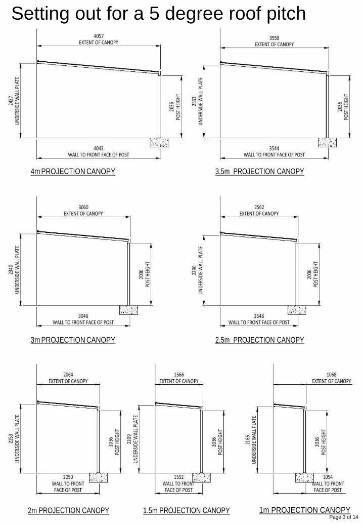
Setting out for a 5 degree roof pitch
4m PROJECTION CANOPY 3.5m PROJECTION CANOPY
3m PROJECTION CANOPY 2.5m PROJECTION CANOPY
2m PROJECTION CANOPY 1.5m PROJECTION CANOPY 1m PROJECTION CANOPY Page 4 of 14
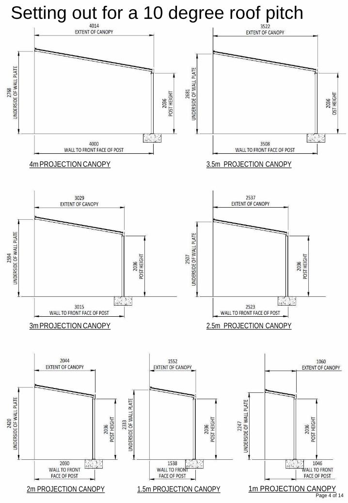
Setting out for a 10 degree roof pitch
4m PROJECTION CANOPY 3.5m PROJECTION CANOPY
3m PROJECTION CANOPY 2.5m PROJECTION CANOPY
2m PROJECTION CANOPY 1.5m PROJECTION CANOPY 1m PROJECTION CANOPY Page 5 of 14
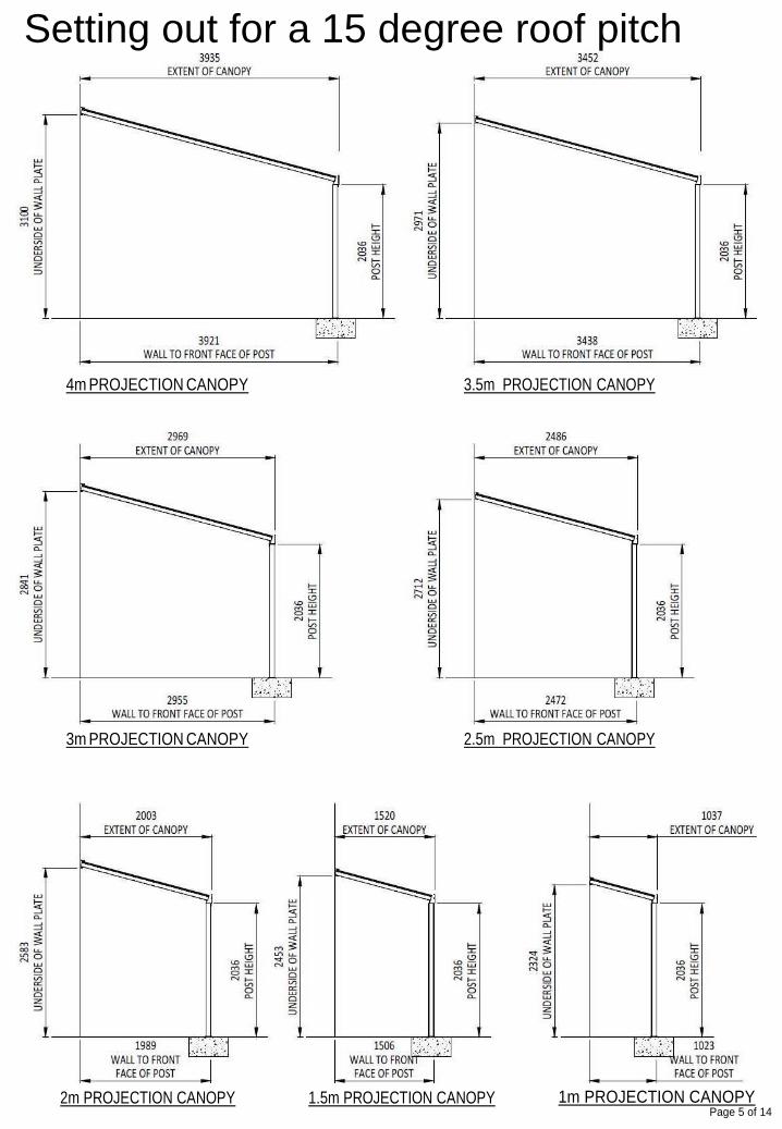
Setting out for a 15 degree roof pitch
4m PROJECTION CANOPY 3.5m PROJECTION CANOPY
3m PROJECTION CANOPY 2.5m PROJECTION CANOPY
Page 6 of 14
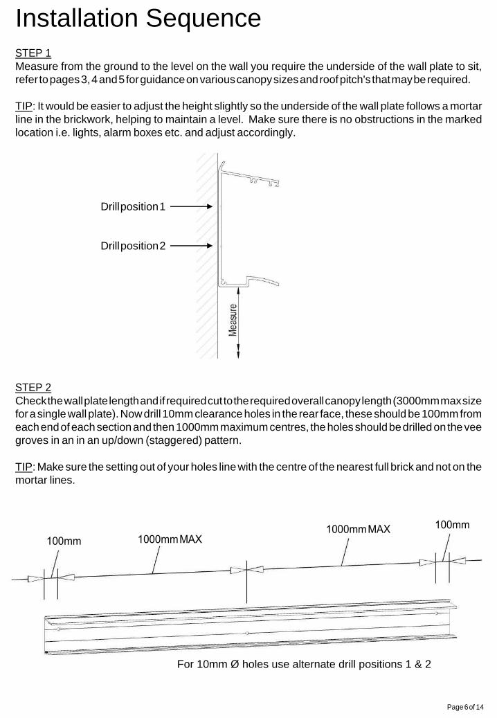
Installation Sequence STEP 1
Measure from the ground to the level on the wall you require the underside of the wall plate to sit,
refer to pages 3, 4 and 5 for guidance on various canopy sizes and roof pitch's that may be required.
TIP: It would be easier to adjust the height slightly so the underside of the wall plate follows a mortar
line in the brickwork, helping to maintain a level. Make sure there is no obstructions in the marked
location i.e. lights, alarm boxes etc. and adjust accordingly.
Drill position 1
Drill position 2
STEP 2
Check the wall plate length and if required cut to the required overall canopy length (3000mm max size
for a single wall plate). Now drill 10mm clearance holes in the rear face, these should be 100mm from
each end of each section and then 1000mm maximum centres, the holes should be drilled on the vee
groves in an in an up/down (staggered) pattern.
TIP: Make sure the setting out of your holes line with the centre of the nearest full brick and not on the
mortar lines.
For 10mm Ø holes use alternate drill positions 1 & 2
Page 7 of 14
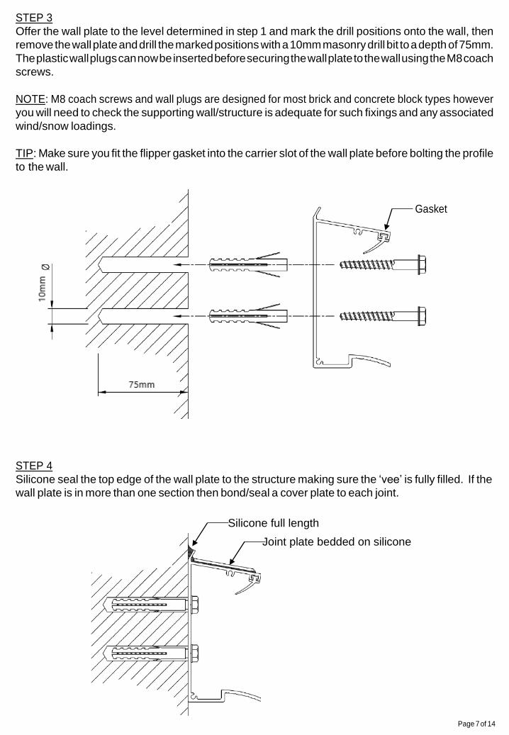
STEP 3
Offer the wall plate to the level determined in step 1 and mark the drill positions onto the wall, then
remove the wall plate and drill the marked positions with a 10mm masonry drill bit to a depth of 75mm.
The plastic wall plugs can now be inserted before securing the wall plate to the wall using the M8 coach
screws.
NOTE: M8 coach screws and wall plugs are designed for most brick and concrete block types however
you will need to check the supporting wall/structure is adequate for such fixings and any associated
wind/snow loadings.
TIP: Make sure you fit the flipper gasket into the carrier slot of the wall plate before bolting the profile
to the wall.
Gasket
STEP 4
Silicone seal the top edge of the wall plate to the structure making sure the ‘vee’ is fully filled. If the
wall plate is in more than one section then bond/seal a cover plate to each joint.
Silicone full length
Joint plate bedded on silicone
Page 8 of 14
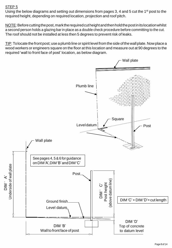
STEP 5
Using the below diagrams and setting out dimensions from pages 3, 4 and 5 cut the 1st post to the
required height, depending on required location, projection and roof pitch.
NOTE: Before cutting the post, mark the required cut height and then hold the post in its location whilst
a second person holds a glazing bar in place as a double check procedure before committing to the cut.
The roof should not be installed at less then 5 degrees to prevent risk of leaks.
TIP: To locate the front post; use a plumb line or spirit level from the side of the wall plate. Now place a
wood workers or engineers square on the floor at this location and measure out at 90 degrees to the
required ‘wall to front face of post’ location, as below diagram.
Wall plate
Plumb line
Square
Level datum Post
Wall plate
Post
Ground finish
Level datum
DIM ‘B’
Wall to front face of post
DIM ‘D’
Top of concrete
to datum level
DIM ‘C’ + DIM ‘D’= cut length
DIM
‘A
’
Un
de
rsid
e o
f wa
ll p
late
DIM
‘C
’
Po
st
he
ight
(ab
ove
da
tum
lin
e)
See pages 4, 5 & 6 for guidance
on DIM ‘A’, DIM ‘B’ and DIM ‘C’
Page 9 of 14
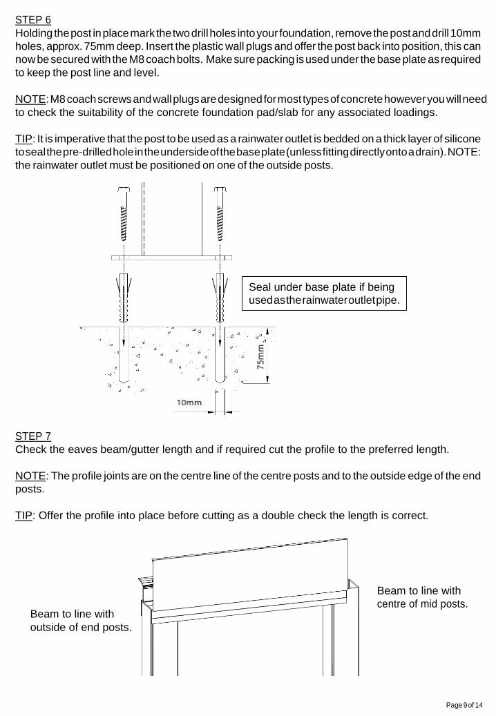
STEP 6
Holding the post in place mark the two drill holes into your foundation, remove the post and drill 10mm
holes, approx. 75mm deep. Insert the plastic wall plugs and offer the post back into position, this can
now be secured with the M8 coach bolts. Make sure packing is used under the base plate as required
to keep the post line and level.
NOTE: M8 coach screws and wall plugs are designed for most types of concrete however you will need
to check the suitability of the concrete foundation pad/slab for any associated loadings.
TIP: It is imperative that the post to be used as a rainwater outlet is bedded on a thick layer of silicone
to seal the pre-drilled hole in the underside of the base plate (unless fitting directly onto a drain). NOTE:
the rainwater outlet must be positioned on one of the outside posts.
STEP 7
Check the eaves beam/gutter length and if required cut the profile to the preferred length.
NOTE: The profile joints are on the centre line of the centre posts and to the outside edge of the end
posts.
TIP: Offer the profile into place before cutting as a double check the length is correct.
Beam to line with
outside of end posts.
Beam to line with
centre of mid posts.
Seal under base plate if being
used as the rainwater outlet pipe.
Page 10 of 14
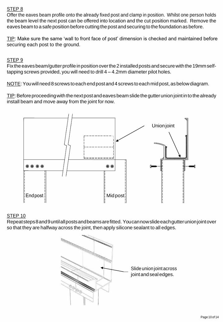
STEP 8
Offer the eaves beam profile onto the already fixed post and clamp in position. Whilst one person holds
the beam level the next post can be offered into location and the cut position marked. Remove the
eaves beam to a safe position before cutting the post and securing to the foundation as before.
TIP: Make sure the same ‘wall to front face of post’ dimension is checked and maintained before
securing each post to the ground.
STEP 9
Fix the eaves beam/gutter profile in position over the 2 installed posts and secure with the 19mm self-
tapping screws provided, you will need to drill 4 – 4.2mm diameter pilot holes.
NOTE: You will need 8 screws to each end post and 4 screws to each mid post, as below diagram.
TIP: Before proceeding with the next post and eaves beam slide the gutter union joint in to the already
install beam and move away from the joint for now.
STEP 10
Repeat steps 8 and 9 until all posts and beams are fitted. You can now slide each gutter union joint over
so that they are halfway across the joint, then apply silicone sealant to all edges.
Slide union joint across
joint and seal edges.
Union joint
Mid post
Page 11 of 14
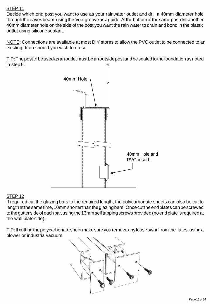
STEP 11
Decide which end post you want to use as your rainwater outlet and drill a 40mm diameter hole
through the eaves beam, using the ‘vee’ groove as a guide. At the bottom of the same post drill another
40mm diameter hole on the side of the post you want the rain water to drain and bond in the plastic
outlet using silicone sealant.
NOTE: Connections are available at most DIY stores to allow the PVC outlet to be connected to an
existing drain should you wish to do so
TIP: The post to be used as an outlet must be an outside post and be sealed to the foundation as noted
in step 6.
40mm Hole
40mm Hole and
PVC insert.
STEP 12
If required cut the glazing bars to the required length, the polycarbonate sheets can also be cut to
length at the same time, 10mm shorter than the glazing bars. Once cut the end plates can be screwed
to the gutter side of each bar, using the 13mm self tapping screws provided (no end plate is required at
the wall plate side).
TIP: If cutting the polycarbonate sheet make sure you remove any loose swarf from the flutes, using a
blower or industrial vacuum.

Page 12 of 14
U profile
U profile
STEP 13
At ground level assemble the first panel by push fitting an end bar to one side of the polycarbonate
sheet, then ‘u’ profiles to the top and bottom edges before finally push fitting a mid bar to the last side.
NOTE: Apply a small amount of washing up liquid to the edges of the polycarbonate to ease the fitting
of the glazing bars.
TIP: On longer bars push the corner of the polycarbonate sheet in first and then work along the bar
length.
Mid bar
STEP 14
Lift the assembled panel into place making sure the end bar is to the outside of the canopy and the end
plates are into the gutter. Once the panel is located secure it with 2x 19mm self-tapping screws per
fixing point, from underneath through the wall plate and eaves beam into the glazing bar.
NOTE: You will need to drill 4 – 4.2mm pilot holes for the 19mm self tapping screws. Before fitting the
panel to the eaves beam check that the posts remain plumb and level.
TIP: Make sure that the panel is inserted into the wall plate, past the flipper gasket and that there is
sufficient overhang into the gutter profile. Finally make sure that the outside edge of the panel does not
go past the face of the wall plate or eaves beam as this will foul the end plates later on.
Edge of bar to line with
outside edge of gutter/post.
2 screws at each
end (side by side)

Page 13 of 14
U profile
No bar
U profile
STEP 15
At ground level assemble the next ‘mid’ panel by pushing fitting a mid bar to one side of the
polycarbonate sheet then ‘u’ profiles to the top and bottom edges.
NOTE: Apply a small amount of washing up liquid to the edges of the polycarbonate to ease the fitting
of the glazing bars.
TIP: Make sure the ‘mid bar is on the correct side of the polycarbonate so that the glazing run can be
continued.
Mid bar
STEP 16
Locate this panel onto the roof, as before, and push fit (the side with no bar on) into the open end of
the already fitted panel. Once the panel is located secure it with 2x 19mm self-tapping screws per fixing
point, from underneath through the wall plate and eaves beam into the glazing bar, as step 14.
NOTE: Apply a small amount of washing up liquid to the edges of the polycarbonate to ease the fitting
of the glazing bars.
TIP: On longer bars push the corner of the polycarbonate sheet in first, at the wall plate end, and then
work down the bar length to the gutter.
2 screws at
each end
Page 14 of 14
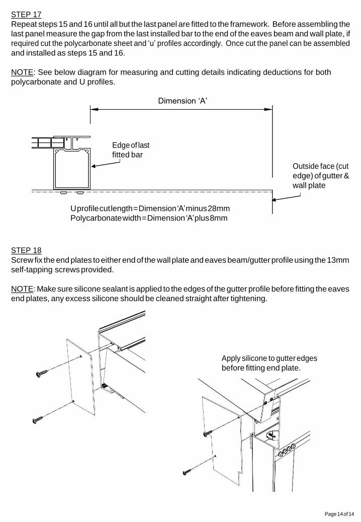
STEP 17
Repeat steps 15 and 16 until all but the last panel are fitted to the framework. Before assembling the
last panel measure the gap from the last installed bar to the end of the eaves beam and wall plate, if
required cut the polycarbonate sheet and ‘u’ profiles accordingly. Once cut the panel can be assembled
and installed as steps 15 and 16.
NOTE: See below diagram for measuring and cutting details indicating deductions for both
polycarbonate and U profiles.
Dimension ‘A’
Edge of last
fitted bar
Outside face (cut
edge) of gutter &
wall plate
U profile cut length = Dimension ‘A’ minus 28mm
Polycarbonate width = Dimension ‘A’ plus 8mm
STEP 18
Screw fix the end plates to either end of the wall plate and eaves beam/gutter profile using the 13mm
self-tapping screws provided.
NOTE: Make sure silicone sealant is applied to the edges of the gutter profile before fitting the eaves
end plates, any excess silicone should be cleaned straight after tightening.
Apply silicone to gutter edges
before fitting end plate.


![PARTS LIST · 2016. 1. 28. · k5 909 6394 000 1 latch squeegee kit k6 9097637000 1 squeegee fixing kit k7 9099322000 1 hardware squeegee support kit part notes: [1] - option. 13](https://img.pdfslide.us/doc/110x75/6135fd420ad5d2067647bab6/parts-list-2016-1-28-k5-909-6394-000-1-latch-squeegee-kit-k6-9097637000-1-squeegee.jpg)