Embed Size (px)
Citation preview
KISSsoft 03/2013 – Tutorial 7
Roller bearings
KISSsoft AG
Rosengartenstrasse 4
8608 Bubikon
Switzerland
Tel: +41 55 254 20 50
Fax: +41 55 254 20 51
www.KISSsoft.AG

15.02.2013 2 / 15
Contents
1 Task ......................................................................................................................................................... 3 1.1 General ........................................................................................................................................... 3 1.2 Task ................................................................................................................................................ 3 1.3 Modeling the system ....................................................................................................................... 4 1.4 Adding Bearings ............................................................................................................................. 5 1.5 Roller bearing calculation ............................................................................................................... 7 1.6 Settings ........................................................................................................................................... 8
2 Further Calculations ............................................................................................................................... 11 2.1 Calculation with load spectra ........................................................................................................ 11 2.2 Calculating the thermally permissible service speed limit ............................................................ 13 2.3 Extending the Roller Bearings Database ...................................................................................... 14 2.4 Calculating a single bearing with known loads ............................................................................. 15
15.02.2013 3 / 15
1 Task
1.1 General
In KISSsoft roller bearings are usually analyzed as part of the shaft analysis process. The calculation of
journal bearings (which are also available in KISSsoft) is not discussed here. In this tutorial, roller bearings
are not viewed separately from their environment. Instead, they are treated as part of a system that consists
of a shaft, external loads and bearings. The great advantage of this approach is that the calculation of loads
on the roller bearing is performed automatically and therefore is less prone to user errors. The same applies
to statically over-determined systems. You can also analyze individual bearings that are subject to a known
load. For more information about this, see section 2.4.
1.2 Task
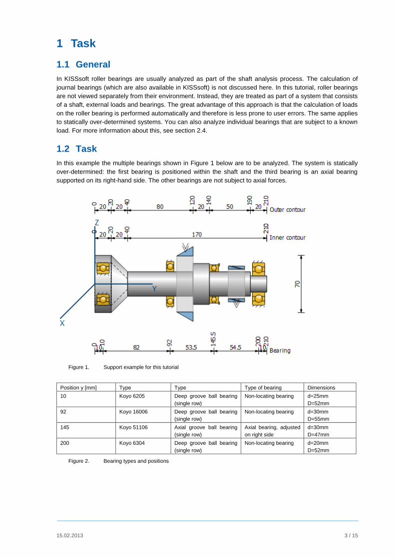
In this example the multiple bearings shown in Figure 1 below are to be analyzed. The system is statically
over-determined: the first bearing is positioned within the shaft and the third bearing is an axial bearing
supported on its right-hand side. The other bearings are not subject to axial forces.
Figure 1. Support example for this tutorial
Position y [mm] Type Type Type of bearing Dimensions
10 Koyo 6205 Deep groove ball bearing
(single row)
Non-locating bearing d=25mm
D=52mm
92 Koyo 16006 Deep groove ball bearing
(single row)
Non-locating bearing d=30mm
D=55mm
145 Koyo 51106 Axial groove ball bearing
(single row)
Axial bearing, adjusted
on right side
d=30mm
D=47mm
200 Koyo 6304 Deep groove ball bearing
(single row)
Non-locating bearing d=20mm
D=52mm
Figure 2. Bearing types and positions

15.02.2013 4 / 15
1.3 Modeling the system
First of all, model the shaft geometry as shown in Figure 1 (see also Tutorial 006: Shaft editor). In a second
step, define the two force elements (bevel gear and cylindrical gear) with the data shown in Figure 3.
Position
[mm]
Type Angle Pitch
diameter
[mm]
Width [mm] Power [kW] Direction
Meshing [°] Helix [°]
110 Bevel gear 20 0 80 20 30 driven
173 Cylindrical
gear 20 15 40 20 30 driving
Figure 3. Loads
The reference cone angle of the bevel gear is δ=30°.
Figure 4. Definition of the force elements
After this, the following system should be visible in the graphical shaft editor:

15.02.2013 5 / 15
Figure 5. Geometry of the shaft and force elements
1.4 Adding Bearings
In the "Elements-tree", right-hand mouse click on "Bearing" and then select the "Roller bearing" option
from the context menu:
Figure 6. "Elements-tree" with the context menu for the "Bearing" group
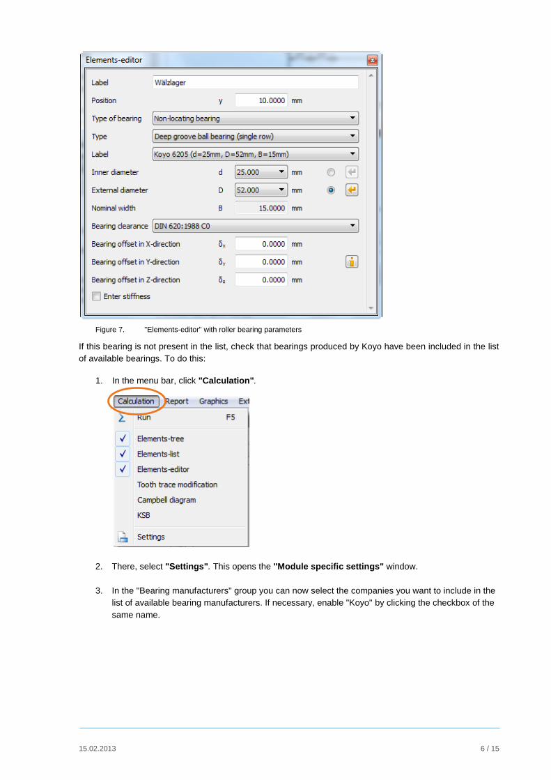
As shown in Figure 6, the "Elements-editor" lists the most important bearing parameters.
To position the bearing at y=10 mm within the shaft, click the radio button to the right of the "External
diameter" input field. From the drop-down list with the same name, select the entry 52.00 mm and select
"Type Koyo 6205 (d=25 mm, D=52 mm, B=15 mm)" from the drop-down list for the label. Then click the
sizing button to the right of the drop-down lists for the inner diameter or outer diameter to modify the
relevant diameter to the shaft's geometry at the specified position.
15.02.2013 6 / 15
Figure 7. "Elements-editor" with roller bearing parameters
If this bearing is not present in the list, check that bearings produced by Koyo have been included in the list
of available bearings. To do this:
1. In the menu bar, click "Calculation".
2. There, select "Settings". This opens the "Module specific settings" window.
3. In the "Bearing manufacturers" group you can now select the companies you want to include in the
list of available bearing manufacturers. If necessary, enable "Koyo" by clicking the checkbox of the
same name.

15.02.2013 7 / 15
Figure 8. Click OK to close the window.
The system comprising shaft, loads and bearings should now look like the one shown in Figure 1.
1.5 Roller bearing calculation
Start the shaft calculation by clicking on in the toolbar or else press F5 to run the roller bearing
calculation. You can see a quick overview of the results in the "Results" window (see Figure 9). Please
note that you must enter the bearing names manually.
Figure 9. "Results" window with a summary overview of the roller bearing analysis
15.02.2013 8 / 15
In the "bearing service life" list you will now see the following values for each bearing:
S0 Static safety
Lnh Rating life in [h]
Lnmh Modified rating life in [h]1
Lnrh Basic reference rating life according to ISO/TS 16281 in [h]2
Lnmrh Modified reference rating life according to ISO/TS 16281 in [h]1,2
The bearing reaction force list shows the reaction forces and moments for each component (see Figure 10).
Here the Fy component refers to the axial force, and the My component refers to the torque.
Figure 10. Components of bearing reaction forces and moments
1.6 Settings
Some settings have a direct effect on roller bearing analysis. These parameters are listed below.
Figure 11. "Strength" group in the "Basic data" tab with values that have a direct effect on roller bearing analysis
1 If you select "Enhanced bearing service life according to ISO 281" in the "Basic data" tab
2 If you select "Roller bearing service life according to ISO/TS 16281" in the drop-down list for “Roller bearing” in the "Basic
data" tab.
(Fx, Fy, Fz)
(Mx, My, Mz)

15.02.2013 9 / 15
Speed: the higher the speed, the shorter the rating life in [h]
Sense of rotation: possibly changes the sign of axial load, for example, this happens when helical gears are
used. This changes the effect of load on the bearing.
Lubricant temperature: a higher lubricant temperature reduces the service life coefficient.
Roller bearing: in the roller bearing drop-down list you can select one of the four following options:
"Roller bearings, classic calculation (contact angle not considered)"
Roller bearings primarily place constraints on the degree of freedom of movement in displacement
and/or rotation, which is why they are modeled in this way when you select this option. You can
enter any value as the stiffnesses for translation and rotation, no matter what type or size of
bearing is involved. Any correlations between axial and radial forces (i.e. as in tapered roller
bearings) are ignored.
"Roller bearings, classic calculation (contact angle considered)" The same as stated before applies, but with the difference that the correlation between axial and
radial forces, such as experienced by tapered roller bearings, is included in the calculation.
"Roller bearing stiffness calculated from inner geometry"
This takes into account internal roller bearing data, such as roller diameter, race radius to
determine bearing stiffness. If no detailed data is available, it will be estimated on the basis of the
size and type of bearing.
"Roller bearing service life according to ISO/TS 16281"
Service life calculation taking into account internal bearing geometry. The results are displayed in
the "Results" window with Lnrh or Lnmrh.
"Modified rating life according to ISO 281"
If a flag is set in this checkbox, the influence of the lubricant is taken into consideration in the bearing rating
life calculation. The results are displayed in the "Results" window with Lnmh or Lnmrh.
Figure 12. "Environment" group in the "Basic data" tab with lubricant parameters
Lubrication: the choice of the type of lubricant affects the service life coefficient.
Impurity: the impurity coefficient eC affects the service life coefficient.
15.02.2013 10 / 15
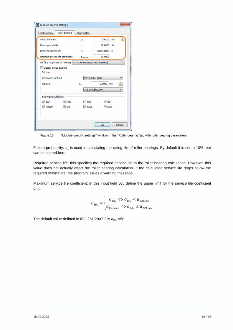
Figure 13. "Module specific settings" window in the "Roller bearing" tab with roller bearing parameters
Failure probability: a1 is used in calculating the rating life of roller bearings. By default it is set to 10%, but
can be altered here.
Required service life: this specifies the required service life in the roller bearing calculation. However, this
value does not actually affect the roller bearing calculation. If the calculated service life drops below the
required service life, the program issues a warning message.
Maximum service life coefficient: In this input field you define the upper limit for the service life coefficient
αISO.
max,max,
max,
ISOISOISO
ISOISOISO
ISOaaa
aaaa
The default value defined in ISO 281:2007-2 is αISO =50.

15.02.2013 11 / 15
2 Further Calculations
2.1 Calculation with load spectra
In the "Basic data" tab, in the drop-down list for load spectra, you can specify whether the load spectra
defined when the shaft was modeled (e.g. cylindrical gear) are to be taken into account (see Figure 14).
Figure 14. Drop-down list for load spectra in "Basic data"
To do this, select the "Consider load spectra" option.
Figure 15. Example that takes a load spectrum into consideration for the force element cylindrical gear
To add your own load spectrum entry to the database, follow these steps:
1. Open the database tool via "Extras" "Database tool".
2. At the prompt (for authorization to write data to the database), click Yes. This opens the database
tool window.
3. Here, select the Load spectra table and click Edit. The database tool window now shows a list of
the entries in the LASTKOLL (load spectra) table.
4. You now have two options for defining your own load spectrum: Either select a data record from the
list and change it, or generate an entirely new data record. If you decide to use the first option,
select an existing data record from the list and then click the button.
5. If you want to create a completely new entry, click the button without first selecting an existing
entry.
6. In both cases, the "Create a new entry" dialog window appears. Here you can input the name of
your choice for your load spectrum in the "Label" input field.

15.02.2013 12 / 15
7. Here you can either enter the actual load spectrum directly, in the table in the lower part of the
window, or input the name of the file to be used for the load spectrum in the "File name" input
field. The file name must have the dat file extension, e.g. own load spectra.dat and be saved to
the <KISSsoft installation folder>/DAT folder.
8. If a file with the same name is already present, click the "Edit" button to start an editor with which
you can edit the file contents.
In each case you see the frequency, torque or power factor and speed factor in a line, separated by tab
spaces. In Figure 16 you see the "meinLastKollektiv.dat" file as it appears in the Windows editor.
Figure 16. Example of a file with your own load spectrum data. The values are displayed in a line,
each separated by a tab
The values in this file are multipliers of the reference values "Power" or "Torque" and "Speed".
Example:
Let us suppose that you have entered the following reference values in the Basic data input window or in
the Elements-editor for the cylindrical gear force element:
P = 115kW, n = 1500U/min
In addition, you then decide to input multipliers for power and not for torque (see Figure 17).
Figure 17. "Create a new entry" window with the efficiency factor (power) selected
In the Input drop-down list you can specify whether you want to multiply the power or the torque with the
values of the load spectrum. For the load spectrum shown in Figure 16 you then receive the absolute
values, as displayed in Figure 18:
15.02.2013 13 / 15
Frequency [%] Power [kW] Speed [1/min]
10 0 0
20 103.5 1200
21 34.5 2400
34 69 1500
10 57.5 1650
5 149.5 600
Figure 18. Example of a load spectrum
2.2 Calculating the thermally permissible service speed limit
The method used to determine the thermally permissible service speed is described in DIN 732. This limit
can differ greatly from other permitted service speeds because the reference conditions only apply to fully
defined cases. In order to define the thermally permissible operating limit, you must first define the thermal
nominal speed for each case. This is the bearing-specific speed of rotation reached under predefined
operating conditions such that the heat development (friction) balances the heat dissipation (through
bearing contact and lubrication). Mechanical or kinematic criteria are not taken into account for this speed.
The reference values (temperatures, load, lubricant viscosity, reference surface of the bearing etc.) have
been fixed so that the reference speeds with either oil or grease lubricated bearings will result in identical
values.
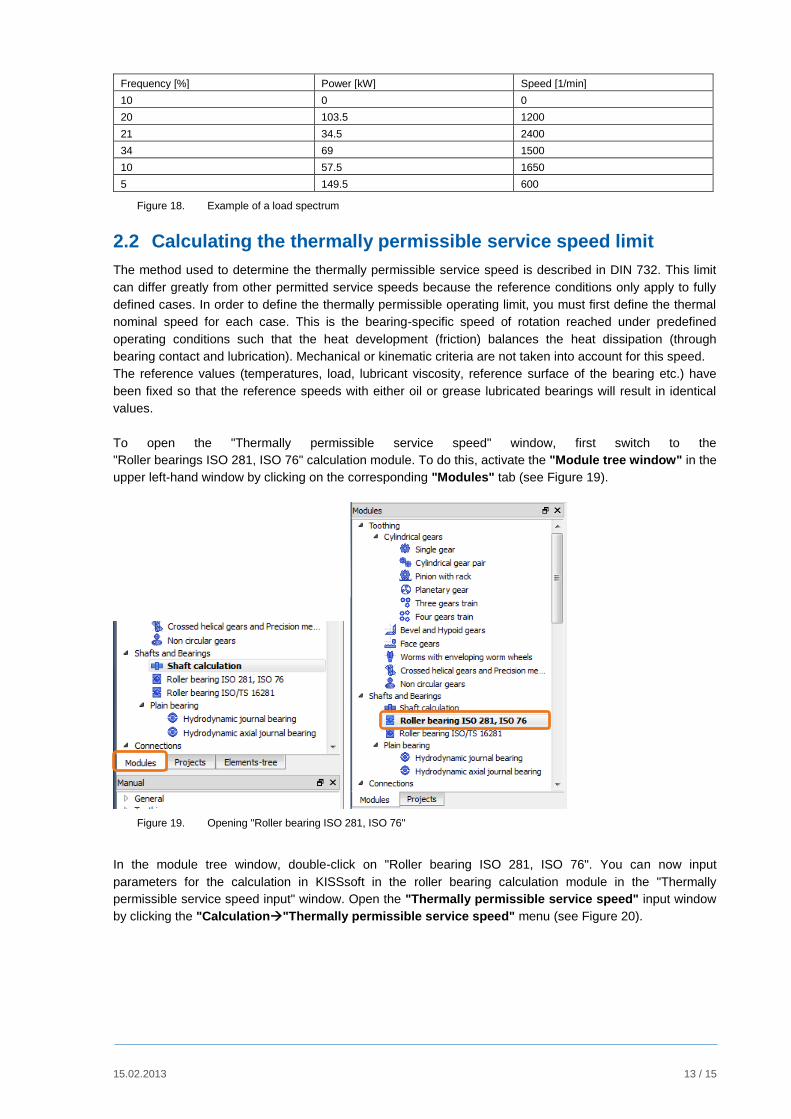
To open the "Thermally permissible service speed" window, first switch to the
"Roller bearings ISO 281, ISO 76" calculation module. To do this, activate the "Module tree window" in the
upper left-hand window by clicking on the corresponding "Modules" tab (see Figure 19).
Figure 19. Opening "Roller bearing ISO 281, ISO 76"
In the module tree window, double-click on "Roller bearing ISO 281, ISO 76". You can now input
parameters for the calculation in KISSsoft in the roller bearing calculation module in the "Thermally
permissible service speed input" window. Open the "Thermally permissible service speed" input window
by clicking the "Calculation"Thermally permissible service speed" menu (see Figure 20).

15.02.2013 14 / 15
Figure 20. Activating the "Thermally permissible service speed" input screen
Figure 21. Active "Thermally permissible operating speed" tab
2.3 Extending the Roller Bearings Database
Data for several thousand roller bearings (from Koyo, NSK, SKF and Timken) are already stored in
KISSsoft. You can also add any missing bearing data to this database. To add a new bearing to the
database follow these steps:
1. Open the database tool via "Extras""Database tool“.
2. At the prompt (for authorization to write data to the database), click Yes. This opens the database
tool window.
3. Here, from database W000, select the table of the corresponding roller bearing type, for example,
description "Deep groove ball bearing (single row)", table "W05WNORM10". Then click "Edit".
The database tool window now shows a list of the entries in the "W05WNORM10" table.
4. You now have two options for defining your own roller bearing. Either select a data record from the
list and change it, or generate an entirely new data record. If you decide to use the first option,
select an existing data record from the list and then click the button.
5. If you want to create a completely new entry, click the button without first selecting an existing
entry.
6. In both cases, the "Create a new entry" dialog window appears. You can now input any name for
your roller bearing in the "Bearing label" input field. You can input parameters for the bearing in
these two tabs: "Basic data" and "Inner geometry". Although you must accept the values in
"Basic data", you can input any values for inner geometry. If no inner geometry data is available, it
is approximated based on the data entered in "Basic data".
7. Then click OK to confirm your entries. In the database tool window, then click "Save" to save your
new entry. Note that no message appears to tell you that you have saved the file successfully. The
roller bearing you have just added appears at the end of the list and has a sequential number >=
20000.

15.02.2013 15 / 15
2.4 Calculating a single bearing with known loads
If you want to analyze a single bearing with a known load, you do not need to model an entire system that
includes a shaft, loads and bearings. Instead, simply click on the "Basic data" tab to open a window with
the same name.
Figure 22. Active "Basic data" tab in roller bearing calculation
Radial loads are defined for each bearing in the "Bearing data" group and axial force is predefined globally
in the "Operating data" group. The distribution of axial force on the individual roller bearing depends on
which type of axial support is selected for each bearing. To perform the calculation then either click or
press "F5".


![KISSsoft 03/2014 Tutorial 8 · PDF fileKISSsoft 03/2014 – Tutorial 8 ... Quality [Q] (DIN 3961) ... The formulas for the calculation according ISO or DIN sometimes results](https://img.pdfslide.us/doc/110x75/5a9eaec57f8b9a71178bb02c/kisssoft-032014-tutorial-8-032014-tutorial-8-quality-q-din-3961-.jpg)