Embed Size (px)
Citation preview
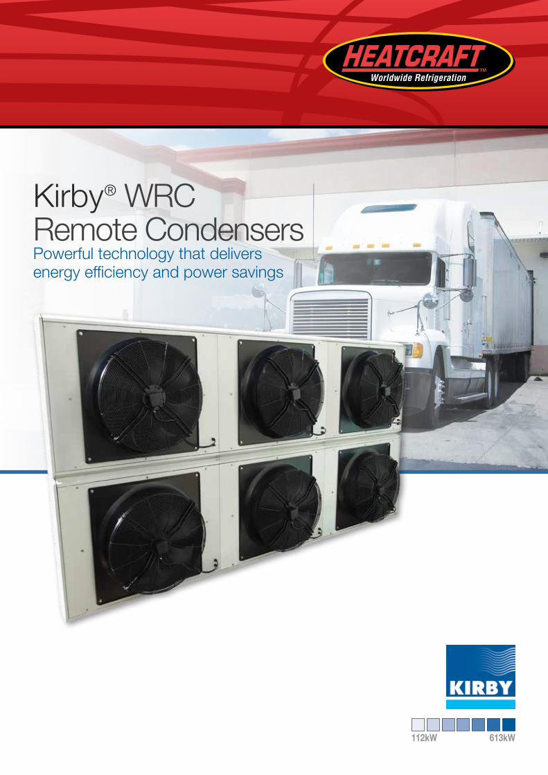
Kirby® WRC Remote Condensers Powerful technology that delivers energy efficiency and power savings
112kW 613kW
2
Kirby WRC Remote CondenserIntroduction
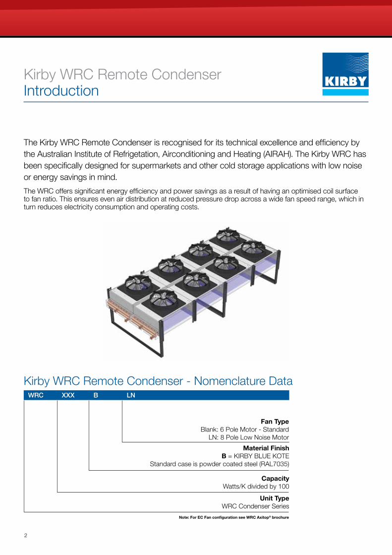
The Kirby WRC Remote Condenser is recognised for its technical excellence and efficiency by the Australian Institute of Refrigetation, Airconditioning and Heating (AIRAH). The Kirby WRC has been specifically designed for supermarkets and other cold storage applications with low noise or energy savings in mind.
The WRC offers significant energy efficiency and power savings as a result of having an optimised coil surface to fan ratio. This ensures even air distribution at reduced pressure drop across a wide fan speed range, which in turn reduces electricity consumption and operating costs.
WRC XXX B LN
Unit Type WRC Condenser Series
Capacity Watts/K divided by 100
Fan TypeBlank: 6 Pole Motor - Standard
LN: 8 Pole Low Noise Motor
Material Finish B = KIRBY BLUE KOTE
Standard case is powder coated steel (RAL7035)
Kirby WRC Remote Condenser - Nomenclature Data
Note: For EC Fan configuration see WRC Axitop® brochure
3
Kirby WRC Remote CondenserProduct Overview
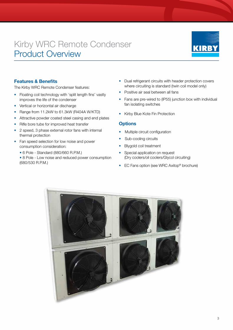
Features & BenefitsThe Kirby WRC Remote Condenser features:
• Floating coil technology with ‘split length fins’ vastly improves the life of the condenser
• Vertical or horizontal air discharge
• Range from 11.2kW to 61.3kW (R404A W/KTD)
• Attractive powder coated steel casing and end plates
• Rifle bore tube for improved heat transfer
• 2 speed, 3 phase external rotor fans with internal thermal protection
• Fan speed selection for low noise and power consumption consideration:
• 6 Pole - Standard (880/660 R.P.M.) • 8 Pole - Low noise and reduced power consumption (680/530 R.P.M.)
• Dual refrigerant circuits with header protection covers where circuiting is standard (twin coil model only)
• Positive air seal between all fans
• Fans are pre-wired to (IP55) junction box with individual fan isolating switches
• Kirby Blue Kote Fin Protection
Options
• Multiple circuit configuration
• Sub-cooling circuits
• Blygold coil treatment
• Special application on request (Dry coolers/oil coolers/Glycol circuiting)
• EC Fans option (see WRC Axitop® brochure)
4
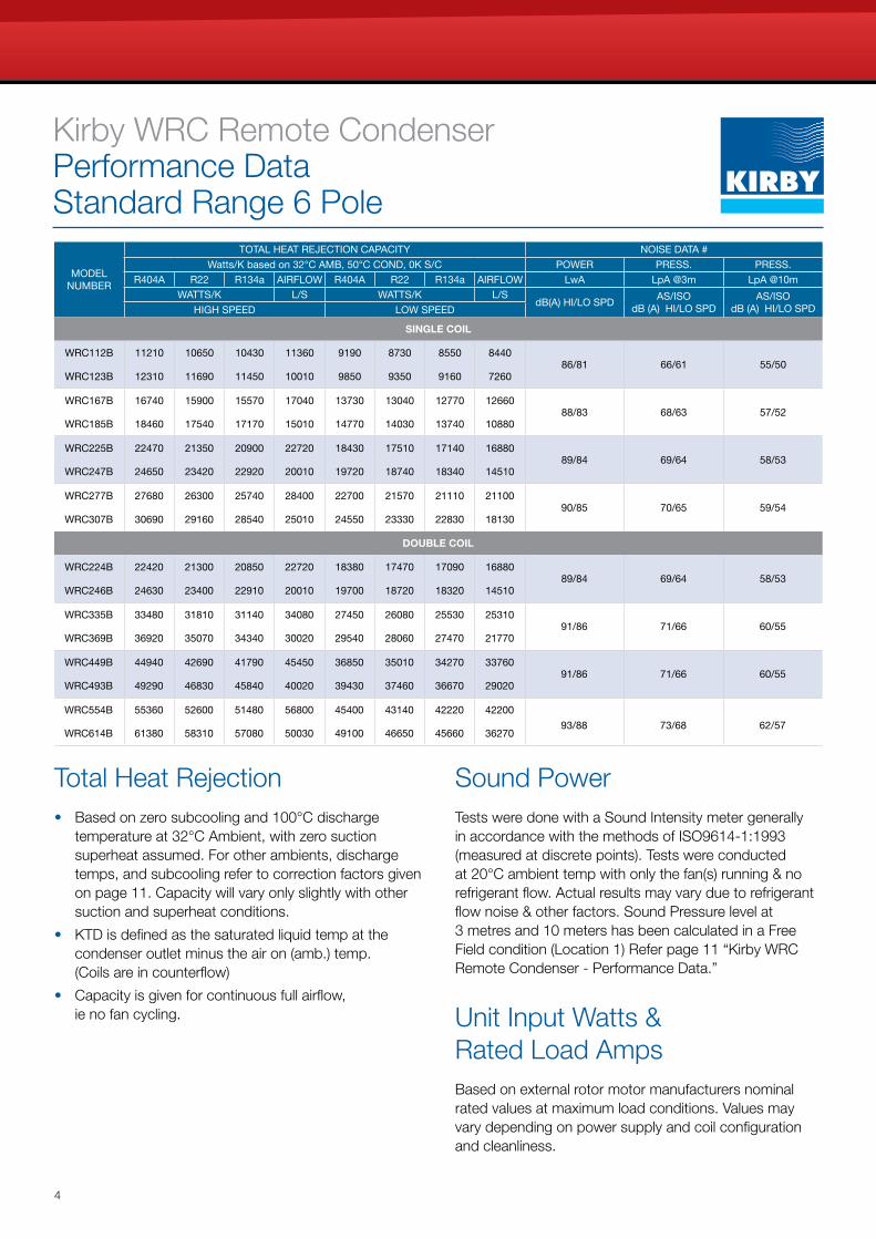
Kirby WRC Remote Condenser Performance Data Standard Range 6 Pole
MODEL NUMBER
TOTAL HEAT REJECTION CAPACITY NOISE DATA #
Watts/K based on 32°C AMB, 50°C COND, 0K S/C POWER PRESS. PRESS.
R404A R22 R134a AIRFLOW R404A R22 R134a AIRFLOW LwA LpA @3m LpA @10m
WATTS/K L/S WATTS/K L/SdB(A) HI/LO SPD
AS/ISOdB (A) HI/LO SPD
AS/ISOdB (A) HI/LO SPDHIGH SPEED LOW SPEED
SINGLE COIL
WRC112B 11210 10650 10430 11360 9190 8730 8550 844086/81 66/61 55/50
WRC123B 12310 11690 11450 10010 9850 9350 9160 7260
WRC167B 16740 15900 15570 17040 13730 13040 12770 1266088/83 68/63 57/52
WRC185B 18460 17540 17170 15010 14770 14030 13740 10880
WRC225B 22470 21350 20900 22720 18430 17510 17140 1688089/84 69/64 58/53
WRC247B 24650 23420 22920 20010 19720 18740 18340 14510
WRC277B 27680 26300 25740 28400 22700 21570 21110 2110090/85 70/65 59/54
WRC307B 30690 29160 28540 25010 24550 23330 22830 18130
DOUBLE COIL
WRC224B 22420 21300 20850 22720 18380 17470 17090 1688089/84 69/64 58/53
WRC246B 24630 23400 22910 20010 19700 18720 18320 14510
WRC335B 33480 31810 31140 34080 27450 26080 25530 2531091/86 71/66 60/55
WRC369B 36920 35070 34340 30020 29540 28060 27470 21770
WRC449B 44940 42690 41790 45450 36850 35010 34270 3376091/86 71/66 60/55
WRC493B 49290 46830 45840 40020 39430 37460 36670 29020
WRC554B 55360 52600 51480 56800 45400 43140 42220 42200
WRC614B 61380 58310 57080 50030 49100 46650 45660 3627093/88 73/68 62/57
Total Heat Rejection• Based on zero subcooling and 100°C discharge
temperature at 32°C Ambient, with zero suction superheat assumed. For other ambients, discharge temps, and subcooling refer to correction factors given on page 11. Capacity will vary only slightly with other suction and superheat conditions.
• KTD is defined as the saturated liquid temp at the condenser outlet minus the air on (amb.) temp. (Coils are in counterflow)
• Capacity is given for continuous full airflow, ie no fan cycling.
Sound PowerTests were done with a Sound Intensity meter generally in accordance with the methods of ISO9614-1:1993 (measured at discrete points). Tests were conducted at 20°C ambient temp with only the fan(s) running & no refrigerant flow. Actual results may vary due to refrigerant flow noise & other factors. Sound Pressure level at 3 metres and 10 meters has been calculated in a Free Field condition (Location 1) Refer page 11 “Kirby WRC Remote Condenser - Performance Data.”
Unit Input Watts & Rated Load AmpsBased on external rotor motor manufacturers nominal rated values at maximum load conditions. Values may vary depending on power supply and coil configuration and cleanliness.
5
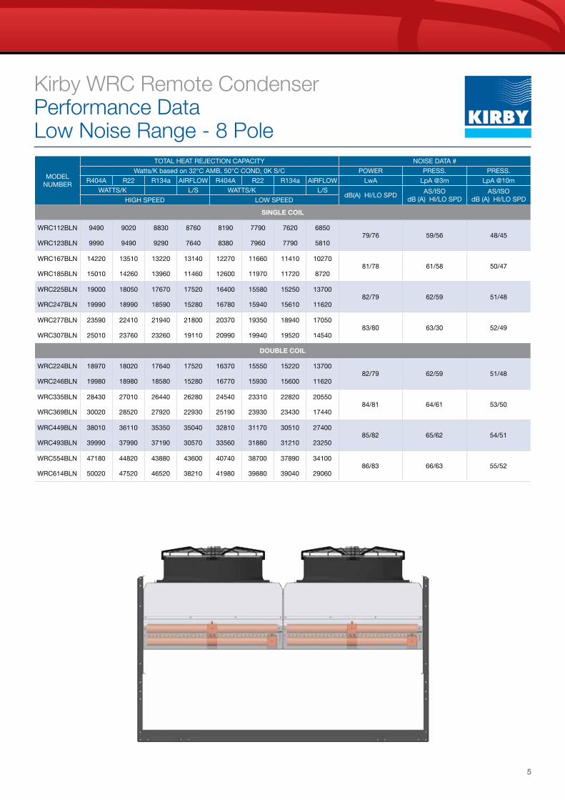
Kirby WRC Remote Condenser Performance Data Low Noise Range - 8 Pole
MODEL NUMBER
TOTAL HEAT REJECTION CAPACITY NOISE DATA #
Watts/K based on 32°C AMB, 50°C COND, 0K S/C POWER PRESS. PRESS.
R404A R22 R134a AIRFLOW R404A R22 R134a AIRFLOW LwA LpA @3m LpA @10m
WATTS/K L/S WATTS/K L/SdB(A) HI/LO SPD
AS/ISOdB (A) HI/LO SPD
AS/ISOdB (A) HI/LO SPDHIGH SPEED LOW SPEED
SINGLE COIL
WRC112BLN 9490 9020 8830 8760 8190 7790 7620 685079/76 59/56 48/45
WRC123BLN 9990 9490 9290 7640 8380 7960 7790 5810
WRC167BLN 14220 13510 13220 13140 12270 11660 11410 1027081/78 61/58 50/47
WRC185BLN 15010 14260 13960 11460 12600 11970 11720 8720
WRC225BLN 19000 18050 17670 17520 16400 15580 15250 1370082/79 62/59 51/48
WRC247BLN 19990 18990 18590 15280 16780 15940 15610 11620
WRC277BLN 23590 22410 21940 21800 20370 19350 18940 1705083/80 63/30 52/49
WRC307BLN 25010 23760 23260 19110 20990 19940 19520 14540
DOUBLE COIL
WRC224BLN 18970 18020 17640 17520 16370 15550 15220 1370082/79 62/59 51/48
WRC246BLN 19980 18980 18580 15280 16770 15930 15600 11620
WRC335BLN 28430 27010 26440 26280 24540 23310 22820 2055084/81 64/61 53/50
WRC369BLN 30020 28520 27920 22930 25190 23930 23430 17440
WRC449BLN 38010 36110 35350 35040 32810 31170 30510 2740085/82 65/62 54/51
WRC493BLN 39990 37990 37190 30570 33560 31880 31210 23250
WRC554BLN 47180 44820 43880 43600 40740 38700 37890 3410086/83 66/63 55/52
WRC614BLN 50020 47520 46520 38210 41980 39880 39040 29060
6
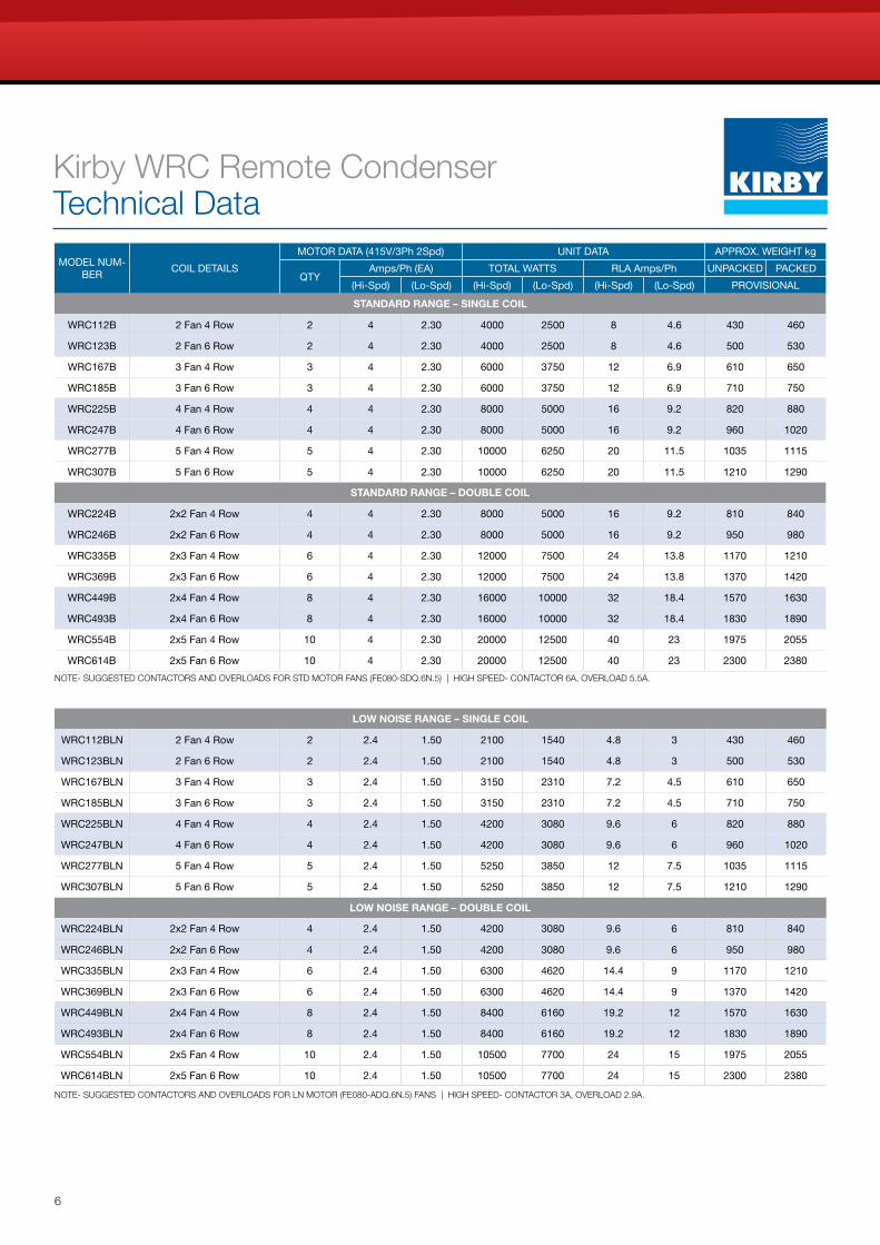
Kirby WRC Remote Condenser Technical Data
MODEL NUM-BER
COIL DETAILS
MOTOR DATA (415V/3Ph 2Spd) UNIT DATA APPROX. WEIGHT kg
QTYAmps/Ph (EA) TOTAL WATTS RLA Amps/Ph UNPACKED PACKED
(Hi-Spd) (Lo-Spd) (Hi-Spd) (Lo-Spd) (Hi-Spd) (Lo-Spd) PROVISIONAL
STANDARD RANGE – SINGLE COIL
WRC112B 2 Fan 4 Row 2 4 2.30 4000 2500 8 4.6 430 460
WRC123B 2 Fan 6 Row 2 4 2.30 4000 2500 8 4.6 500 530
WRC167B 3 Fan 4 Row 3 4 2.30 6000 3750 12 6.9 610 650
WRC185B 3 Fan 6 Row 3 4 2.30 6000 3750 12 6.9 710 750
WRC225B 4 Fan 4 Row 4 4 2.30 8000 5000 16 9.2 820 880
WRC247B 4 Fan 6 Row 4 4 2.30 8000 5000 16 9.2 960 1020
WRC277B 5 Fan 4 Row 5 4 2.30 10000 6250 20 11.5 1035 1115
WRC307B 5 Fan 6 Row 5 4 2.30 10000 6250 20 11.5 1210 1290
STANDARD RANGE – DOUBLE COIL
WRC224B 2x2 Fan 4 Row 4 4 2.30 8000 5000 16 9.2 810 840
WRC246B 2x2 Fan 6 Row 4 4 2.30 8000 5000 16 9.2 950 980
WRC335B 2x3 Fan 4 Row 6 4 2.30 12000 7500 24 13.8 1170 1210
WRC369B 2x3 Fan 6 Row 6 4 2.30 12000 7500 24 13.8 1370 1420
WRC449B 2x4 Fan 4 Row 8 4 2.30 16000 10000 32 18.4 1570 1630
WRC493B 2x4 Fan 6 Row 8 4 2.30 16000 10000 32 18.4 1830 1890
WRC554B 2x5 Fan 4 Row 10 4 2.30 20000 12500 40 23 1975 2055
WRC614B 2x5 Fan 6 Row 10 4 2.30 20000 12500 40 23 2300 2380
LOW NOISE RANGE – SINGLE COIL
WRC112BLN 2 Fan 4 Row 2 2.4 1.50 2100 1540 4.8 3 430 460
WRC123BLN 2 Fan 6 Row 2 2.4 1.50 2100 1540 4.8 3 500 530
WRC167BLN 3 Fan 4 Row 3 2.4 1.50 3150 2310 7.2 4.5 610 650
WRC185BLN 3 Fan 6 Row 3 2.4 1.50 3150 2310 7.2 4.5 710 750
WRC225BLN 4 Fan 4 Row 4 2.4 1.50 4200 3080 9.6 6 820 880
WRC247BLN 4 Fan 6 Row 4 2.4 1.50 4200 3080 9.6 6 960 1020
WRC277BLN 5 Fan 4 Row 5 2.4 1.50 5250 3850 12 7.5 1035 1115
WRC307BLN 5 Fan 6 Row 5 2.4 1.50 5250 3850 12 7.5 1210 1290
LOW NOISE RANGE – DOUBLE COIL
WRC224BLN 2x2 Fan 4 Row 4 2.4 1.50 4200 3080 9.6 6 810 840
WRC246BLN 2x2 Fan 6 Row 4 2.4 1.50 4200 3080 9.6 6 950 980
WRC335BLN 2x3 Fan 4 Row 6 2.4 1.50 6300 4620 14.4 9 1170 1210
WRC369BLN 2x3 Fan 6 Row 6 2.4 1.50 6300 4620 14.4 9 1370 1420
WRC449BLN 2x4 Fan 4 Row 8 2.4 1.50 8400 6160 19.2 12 1570 1630
WRC493BLN 2x4 Fan 6 Row 8 2.4 1.50 8400 6160 19.2 12 1830 1890
WRC554BLN 2x5 Fan 4 Row 10 2.4 1.50 10500 7700 24 15 1975 2055
WRC614BLN 2x5 Fan 6 Row 10 2.4 1.50 10500 7700 24 15 2300 2380
NOTE- SUGGESTED CONTACTORS AND OVERLOADS FOR STD MOTOR FANS (FE080-SDQ.6N.5) | HIGH SPEED- CONTACTOR 6A, OVERLOAD 5.5A.
NOTE- SUGGESTED CONTACTORS AND OVERLOADS FOR LN MOTOR (FE080-ADQ.6N.5) FANS | HIGH SPEED- CONTACTOR 3A, OVERLOAD 2.9A.
7
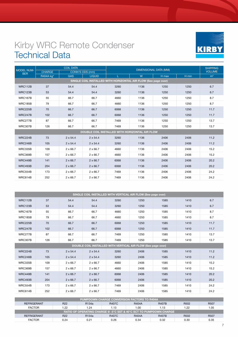
Kirby WRC Remote Condenser Technical Data
MODEL NUM-BER
COIL DATADIMENSIONAL DATA (MM)
SHIPPINGVOLUMECHARGE CONN’S ODS (mm)
R404A kg* GAS LIQUID L W H max H min m3
SINGLE COIL INSTALLED WITH HORIZONTAL AIR FLOW (See page over)
WRC112B 37 54.4 54.4 3260 1136 1250 1250 6.7
WRC123B 53 54.4 54.4 3260 1136 1250 1250 6.7
WRC167B 55 66.7 66.7 4660 1136 1250 1250 8.7
WRC185B 79 66.7 66.7 4660 1136 1250 1250 8.7
WRC225B 70 66.7 66.7 6068 1136 1250 1250 11.7
WRC247B 102 66.7 66.7 6068 1136 1250 1250 11.7
WRC277B 87 66.7 66.7 7469 1136 1250 1250 13.7
WRC307B 126 66.7 66.7 7469 1136 1250 1250 13.7
DOUBLE COIL INSTALLED WITH HORIZONTAL AIR FLOW
WRC224B 73 2 x 54.4 2 x 54.4 3260 1136 2406 2406 11.2
WRC246B 105 2 x 54.4 2 x 54.4 3260 1136 2406 2406 11.2
WRC335B 109 2 x 66.7 2 x 66.7 4660 1136 2406 2406 15.2
WRC369B 157 2 x 66.7 2 x 66.7 4660 1136 2406 2406 15.2
WRC449B 141 2 x 66.7 2 x 66.7 6068 1136 2406 2406 20.2
WRC493B 204 2 x 66.7 2 x 66.7 6068 1136 2406 2406 20.2
WRC554B 173 2 x 66.7 2 x 66.7 7469 1136 2406 2406 24.2
WRC614B 252 2 x 66.7 2 x 66.7 7469 1136 2406 2406 24.2
SINGLE COIL INSTALLED WITH VERTICAL AIR FLOW (See page over)
WRC112B 37 54.4 54.4 3260 1250 1585 1410 6.7
WRC123B 53 54.4 54.4 3260 1250 1585 1410 6.7
WRC167B 55 66.7 66.7 4660 1250 1585 1410 8.7
WRC185B 79 66.7 66.7 4660 1250 1585 1410 8.7
WRC225B 70 66.7 66.7 6068 1250 1585 1410 11.7
WRC247B 102 66.7 66.7 6068 1250 1585 1410 11.7
WRC277B 87 66.7 66.7 7469 1250 1585 1410 13.7
WRC307B 126 66.7 66.7 7469 1250 1585 1410 13.7
DOUBLE COIL INSTALLED WITH VERTICAL AIR FLOW (See page over)
WRC224B 73 2 x 54.4 2 x 54.4 3260 2406 1585 1410 11.2
WRC246B 105 2 x 54.4 2 x 54.4 3260 2406 1585 1410 11.2
WRC335B 109 2 x 66.7 2 x 66.7 4660 2406 1585 1410 15.2
WRC369B 157 2 x 66.7 2 x 66.7 4660 2406 1585 1410 15.2
WRC449B 141 2 x 66.7 2 x 66.7 6068 2406 1585 1410 20.2
WRC493B 204 2 x 66.7 2 x 66.7 6068 2406 1585 1410 20.2
WRC554B 173 2 x 66.7 2 x 66.7 7469 2406 1585 1410 24.2
WRC614B 252 2 x 66.7 2 x 66.7 7469 2406 1585 1410 24.2
PUMPDOWN CHARGE CONVERSION FACTORS TO R404AREFRIGERANT R22 R134a R407C R404A R407B R502 R507
FACTOR 1.22 1.24 1.13 1.00 1.13 1.22 1.05
RATIO OF OPERATING CHARGE @ -5°C SST & 40°C SCT TO PUMPDOWN CHARGEREFRIGERANT R22 R134a R407C R404A R407B R502 R507
FACTOR 0.24 0.21 0.26 0.34 0.32 0.30 0.35
8
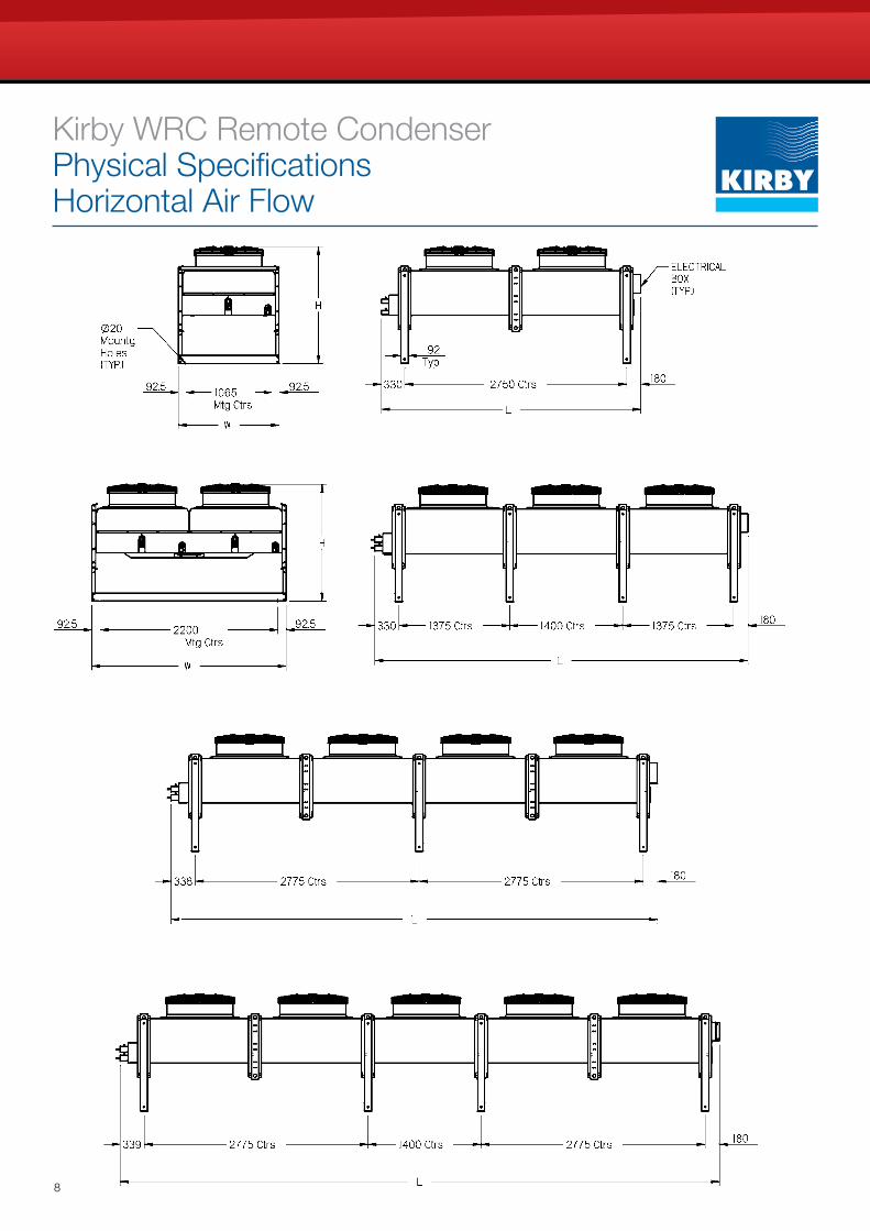
Kirby WRC Remote Condenser Physical Specifications Horizontal Air Flow
9
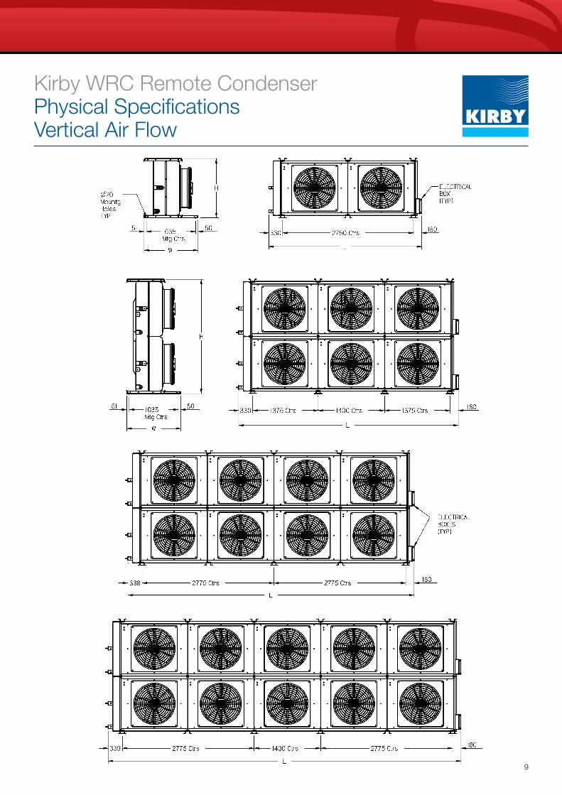
Kirby WRC Remote Condenser Physical Specifications Vertical Air Flow
10
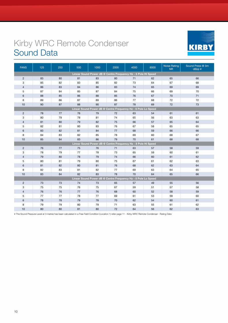
Kirby WRC Remote Condenser Sound Data
# The Sound Pressure Level at 3 metres has been calculated in a Free Field Condition (Location 1) refer page 11 - Kirby WRC Remote Condenser - Rating Data
FANS 125 250 500 1000 2000 4000 8000Noise Rating
NRSound Press @ 3m
dB(a) #
Linear Sound Power dB @ Centre Frequency Hz - 8 Pole Lo Speed
2 73 73 74 73 65 57 49 55 56
3 75 75 76 75 67 59 51 57 58
4 76 76 77 76 68 60 52 58 59
5 77 77 78 77 69 61 53 59 60
6 78 78 79 78 70 62 54 60 61
8 79 79 80 79 71 63 55 61 62
10 80 80 81 80 72 64 56 62 63
Linear Sound Power dB @ Centre Frequency Hz - 8 Pole Hi Speed
2 76 77 75 76 71 63 57 58 59
3 78 79 77 78 73 65 59 60 61
4 79 80 78 79 74 66 60 61 62
5 80 81 79 80 75 67 61 62 63
6 81 82 80 81 76 68 62 63 64
8 82 83 81 82 77 69 63 64 65
10 83 84 82 83 78 70 64 65 66
Linear Sound Power dB @ Centre Frequency Hz - 6 Pole Lo Speed
2 78 77 76 79 72 63 54 61 61
3 80 79 78 81 74 65 56 63 63
4 81 80 79 82 75 66 57 65 64
5 82 81 80 83 76 67 58 65 65
6 83 82 81 84 77 68 59 66 66
8 84 83 82 85 78 69 60 68 67
10 85 84 83 86 79 70 61 68 68
Linear Sound Power dB @ Centre Frequency Hz - 6 Pole Hi Speed
2 83 80 81 83 80 71 62 65 66
3 85 82 83 85 82 73 64 67 68
4 86 83 84 86 83 74 65 69 69
5 87 84 85 87 84 75 66 69 70
6 88 85 86 88 85 76 67 70 71
8 89 86 87 89 86 77 68 72 72
10 90 87 88 90 87 78 69 72 73
11
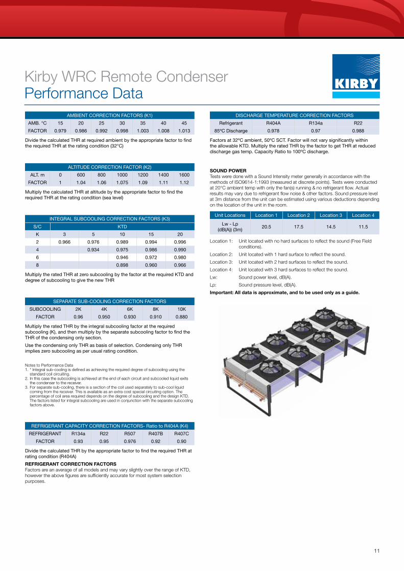
Kirby WRC Remote Condenser Performance Data
AMBIENT CORRECTION FACTORS (K1)
AMB. °C 15 20 25 30 35 40 45
FACTOR 0.979 0.986 0.992 0.998 1.003 1.008 1.013
ALTITUDE CORRECTION FACTOR (K2)
ALT. m 0 600 800 1000 1200 1400 1600
FACTOR 1 1.04 1.06 1.075 1.09 1.11 1.12
INTEGRAL SUBCOOLING CORRECTION FACTORS (K3)
S/C KTD
K 3 5 10 15 20
2 0.966 0.976 0.989 0.994 0.996
4 0.934 0.975 0.986 0.990
6 0.946 0.972 0.980
8 0.898 0.960 0.966
SEPARATE SUB-COOLING CORRECTION FACTORS
SUBCOOLING 2K 4K 6K 8K 10K
FACTOR 0.96 0.950 0.930 0.910 0.880
Multiply the rated THR by the integral subcooling factor at the required subcooling (K), and then multiply by the separate subcooling factor to find the THR of the condensing only section.
Use the condensing only THR as basis of selection. Condensing only THR implies zero subcooling as per usual rating condition.
Notes to Performance Data1. * Integral sub-cooling is defined as achieving the required degree of subcooling using the
standard coil circuiting.2. In this case the subcooling is achieved at the end of each circuit and subcooled liquid exits
the condenser to the receiver.3. For separate sub-cooling, there is a section of the coil used separately to sub-cool liquid
coming from the receiver. This is available as an extra cost special circuiting option. The percentage of coil area required depends on the degree of subcooling and the design KTD. The factors listed for integral subcooling are used in conjunction with the separate subcooling factors above.
REFRIGERANT CAPACITY CORRECTION FACTORS- Ratio to R404A (K4)
REFRIGERANT R134a R22 R507 R407B R407C
FACTOR 0.93 0.95 0.976 0.92 0.90
Divide the calculated THR by the appropriate factor to find the required THR at rating condition (R404A)
REFRIGERANT CORRECTION FACTORS Factors are an average of all models and may vary slightly over the range of KTD, however the above figures are sufficiently accurate for most system selection purposes.
DISCHARGE TEMPERATURE CORRECTION FACTORS
Refrigerant R404A R134a R22
85ºC Discharge 0.978 0.97 0.988
SOUND POWER Tests were done with a Sound Intensity meter generally in accordance with the methods of ISO9614-1:1993 (measured at discrete points). Tests were conducted at 20°C ambient temp with only the fan(s) running & no refrigerant flow. Actual results may vary due to refrigerant flow noise & other factors. Sound pressure level at 3m distance from the unit can be estimated using various deductions depending on the location of the unit in the room.
Location 1: Unit located with no hard surfaces to reflect the sound (Free Field conditions).
Location 2: Unit located with 1 hard surface to reflect the sound.
Location 3: Unit located with 2 hard surfaces to reflect the sound.
Location 4: Unit located with 3 hard surfaces to reflect the sound.
Lw: Sound power level, dB(A).
Lp: Sound pressure level, dB(A).
Important: All data is approximate, and to be used only as a guide.
Unit Locations Location 1 Location 2 Location 3 Location 4
Lw - Lp (dB(A)) (3m)
20.5 17.5 14.5 11.5
Divide the calculated THR at required ambient by the appropriate factor to find the required THR at the rating condition (32°C)
Multiply the calculated THR at altitude by the appropriate factor to find the required THR at the rating condition (sea level)
Factors at 32ºC ambient, 50ºC SCT. Factor will not vary significantly within the allowable KTD. Multiply the rated THR by the factor to get THR at reduced discharge gas temp. Capacity Ratio to 100ºC discharge.
Multiply the rated THR at zero subcooling by the factor at the required KTD and degree of subcooling to give the new THR

All trade marks and registered trade marks are the property of their respective owners and are used for identification purposes only. © Copyright 2015 Heatcraft Australia Pty Limited. Heatcraft Australia continually strive to improve products and processes. We reserve the right to modify product features without notice. Information is correct at time of printing.
Australia Head OfficeHeatcraft Australia Pty Ltd, 286 Horsley Road, Milperra NSW 2214 Locked Bag 63, Wetherill Park NSW 1851 (+61) 2 9774 7155
New Zealand Head OfficeHeatcraft New Zealand Pty Ltd 12 George Bourke Drive, Mt Wellington PO Box 12371 Penrose, Auckland (+64) 9 276 4888
australia 13 23 50heatcraft.com.au
new zealand 0800 653 330heatcraft.co.nz
Kirby Generic Back Page FINAL.indd 1 8/09/2015 10:07:33 AM