Embed Size (px)
Citation preview

KION MultiGas 2000Service Manual
E382 E392E 061 10 02 02

Siemens-Elema AB
KION MultiGas 2000 Service Manual
E382 E392E 061 10 02 022
Notes

E382 E392E 061 10 02 02 Siemens-Elema AB
Service Manual KION MultiGas 2000
3
Contents1. Important .............................................................................................................................42. Introduction ..........................................................................................................................6
2.1 General description ......................................................................................................62.2 Mechanical overview ...................................................................................................72.3 Functional principles ....................................................................................................8
3. Description of functions .......................................................................................................93.1 Water trap ....................................................................................................................93.2 Water trap receptacle...................................................................................................93.3 Nafion tube.................................................................................................................103.4 AION ..........................................................................................................................103.5 O2 sensor ...................................................................................................................123.6 SCM300 PC board .....................................................................................................133.7 Rear panel ..................................................................................................................13
4. Disassembly and assembly ...............................................................................................144.1 General .......................................................................................................................144.2 Handling PC boards ....................................................................................................144.3 Tools ...........................................................................................................................144.4 Water trap receptacle on KMG 2000 .........................................................................154.5 Removal and installation of KMG 2000 in KION ........................................................164.6 Cover ..........................................................................................................................174.7 Internal tubing ............................................................................................................184.8 O2 sensor ...................................................................................................................194.9 AION ..........................................................................................................................204.10 SCM300 PC board with connectors ..........................................................................21
5. Service procedures ............................................................................................................225.1 Functional verification ................................................................................................225.2 Software installation. ..................................................................................................225.3 Calibrations and verifications .....................................................................................245.4 KMG 2000 Service Software .....................................................................................27
6. Troubleshooting .................................................................................................................286.1 General .......................................................................................................................286.2 Problem indentification ..............................................................................................286.3 Prior to troubleshooting ..............................................................................................286.4 Communication ..........................................................................................................286.5 Inaccurate information ...............................................................................................29
7. Preventive maintenance ....................................................................................................297.1 Performing the Preventive maintenance ...................................................................29
8. Diagrams ............................................................................................................................318.1 Functional block diagram ...........................................................................................31
Siemens-Elema AB
KION MultiGas 2000 Service Manual
E382 E392E 061 10 02 024
1. ImportantGeneral• This Service Manual is intended to give service
personnel sufficient knowledge about the KIONMultiGas 2000 (KMG 2000) to be able to diagnoseany possible problem or failure and to identifywhich part or component that causes the problemor failure. The description is limited to a level,which allows the service personnel to trackproblems down to parts that are found in thespare part list.
• This Service Manual is also intended to giveinformation how to perform preventivemaintenance and to make functional checks andcalibrations.
• Documentation for the KMG 2000 consists of:– SC 7000 / SC 9000XL – User’s guide– KION – Operating Manual– KION – Service Manual– KION MultiGas 2000 – Service Manual– KION MultiGas 2000 – Installation Instructions– KION MultiGas 2000 – Spare Parts List
• The SC 7000 / SC 9000XL – User’s guide and theKION – Operating Manual are indispensablecomplements to the Service Manual for properservicing.
Text inside a box is used to highlight importantinformation.
• In addition to the Important information givenhere and in the related documents, always payattention to applicable local and nationalregulations.
• Responsibility for the safe functioning of theequipment reverts to the owner or user in allcases in which service or repair has been done bya non-professional or by persons who are notemployed by or authorized by Siemens, and whenthe equipment is used for other than its intendedpurpose.
• Data on internal pressures are given in Pa (bar).Airway pressures are given in cm H
2O (Pa).
1 hPa = 1 mbar 1 mbar = 1 hPa1 kPa = 10 mbar 1 mbar = 0.1 kPa1 kPa = 0.01 bar 1 bar = 100 kPa1 kPa � 10 cm H2O 1 cm H2O � 0.1 kPa1 kPa � 0.01 at 1 at � 100 kPa1 kPa � 0.01 kgf/cm2 1 kgf/cm2 � 100 kPa1 kPa � 0.01 kp/cm2 1 kp/cm2
� 100 kPa1 kPa � 0.145 psi 1 psi � 6.9 kPa
Symbols used in this manual• ESD sensitive components – Make
sure to take precautions to avoiddamaging ESD sensitive components.
• Special waste – Make sure to dis-card disposables and replaced partsaccording to local regulations and inan environmentally acceptable way.
• Technical training – Refers to theTechnical training supplied bySiemens.
• Service contract – Refers to theService contract supplied bySiemens.
Abbreviations used in this manual• KMG 2000 – KION MultiGas 2000.
• KION Display – Siemens Patient Care Monitors,e. g. SC 7000 or SC 9000XL.
Installation• Only personnel trained and authorized
by Siemens shall be permitted to installthe KMG 2000. The installation andhanding-over procedures are describedin the KION MultiGas 2000 – InstallationInstructions.
Functional check• After any installation, maintenance or service
intervention in the KMG 2000, perform a”Functional verification”. Refer to chapter Serviceprocedures, section Functional verification in thisService Manual.

E382 E392E 061 10 02 02 Siemens-Elema AB
Service Manual KION MultiGas 2000
5
1. ImportantService• The KMG 2000 must be serviced at
regular intervals by personnel trainedand authorized by Siemens.Any maintenance or service must benoted in a log book.
• Preventive maintenance must be performed atleast once every year as long as the unit is notused more than normal. Normal operation isestimated to correspond to approx. 5.000 hoursof operation. Details are found in this ServiceManual, chapter ”Preventive maintenance”.
• It is recommended that maintenanceand service is done as a part of a servicecontract with Siemens.
• All disposable parts shall be discardedaccording to local regulations and in anenvironmentally acceptable way.
• When working with ESD sensitivecomponents, always use a groundedwrist band and a grounded worksurface. Adequate service tools mustalways be used.
To the responsible service personnel• The contents of this document are not binding.
If any significant difference is found between theproduct and this document, please contactSiemens for further information.
• We reserve the right to modify products withoutamending this document or advising the user.
• Only personnel trained and authorizedby Siemens shall be permitted toperform installation, service ormaintenance of the KION and/or theKMG 2000. Only Siemens genuinespare parts must be used. PC boards (spare parts)must always be kept in a package for sensitiveelectronic devices. Siemens will not otherwiseassume responsibility for the materials used, thework performed or any possible consequences ofsame.
Hazard notices• Before disassembling or assembling the KION
and/or the KMG 2000, make sure that the:– Gas supply is disconnected.– Mains power cable is disconnected.– KION power switch is set to Off. If the power
switch is set to Standby or On, the internalbattery will supply power to the PC boards.
– Internal battery is disconnected when workinginside the Power & Communication interface.
– The system is cleaned according to instructionsin the KION – Operating Manual, chapterRoutine cleaning.
• With power supply connected to the KIONSystem, there are energized electrical componentsinside the unit. All personnel must exerciseextreme caution if fault tracing or adjustments areperformed with power supply connected.
Warnings• The KMG 2000 must not be used with flammable
anesthetic agents.
• Water emptied from the water trapshould be disposed of in accordancewith local regulations for contaminatedand biologically hazardous fluids.
• The water trap should be disposed of inaccordance with local regulations forcontaminated and biologically hazardousitems.
• The evacuated gas must be handled in a suitablemanner to prevent hazardous levels of anestheticgases to be built-up in the ambient air.
• Analyzer performance is likely to be degraded inthe presence of operating electrosurgical ordiathermy equipment.

Siemens-Elema AB
KION MultiGas 2000 Service Manual
E382 E392E 061 10 02 026
2. Introduction
2.1 General descriptionThe KION MultiGas 2000 (KMG 2000) is intended forintegration in the KION Anesthesia System.The KMG 2000 delivers gas measurement data to beshown on the KION Display.
The KMG 2000 is a side-stream multigas analyzerintended to monitor respiratory and anesthetic gasessampled from the breathing circuits of adult, pediatricand neonatal patients. The gases measured are O2,CO
2, N
2O, Halothane, Enflurane, Isoflurane,
Sevoflurane and Desflurane in any combination.
All gases in the gas sample, except O2, are identifiedand measured by an infrared sensor. O
2 is identified
and measured by a paramagnetic O2 sensor.
The information created by the KMG 2000 isdelivered to the KION Display where the informationis calculated and shown.
MG
A-0
01X
KION
Display
KION
MultiGas 2000
E382 E392E 061 10 02 02 Siemens-Elema AB
Service Manual KION MultiGas 2000
7
2.2 Mechanical overview2.2.1 Water trap
The DRYLINE™ water trap consists of two parts, afilter housing with hydrophobic anti-bacterial filter anda container for separated waste.
2.2.2 Water trap receptacle
The water trap is connected to the water trapreceptacle. Switches on the water trap receptacledetects that a water trap is connected. The samplegas flow is routed from the water trap receptacle tothe KMG 2000 via a NafionTM tube.
2.2.3 AION
The AION™ is the gas measuring unit. It contains thefollowing modules:
• Pneumatic Module: Interconnection between thedifferent parts of the gas sampling system. Includestwo solenoid valves; the zero calibration valve (ZCV)and the purge flow valve (PFV).
• Gas Measurement Bench (GMB): Identifies andmeasures the gases CO2, N2O, Halothane,Enflurane, Isoflurane, Desflurane and Sevoflurane.
• Pump Module: Creates and controls the gassampling flow.
• AION PC board: Integrated in the AION basemodule. Contains CPU, EEPROM and software.Controls the gas sampling system and performscalculations from the measured parameters.
2.2.4 O2 sensor
The paramagnetic O2 sensor identifies and measures
the O2 concentration in the gas sample.
2.2.5 SCM300 PC board
The SCM300 PC board is an interconnection betweenmodules within the KMG 2000 and includes also allexternal electrical connectors. The RS232 protocolconverters are located on this PC board.
A metal shield covering the external connectorsmounted on the SCM300 PC board protects theinterior from electromagnetic interference from theoutside.
2.2.6 Rear panel
The evacuation outlet connector and all externalelectrical connectors are mounted on the rear panel.

Siemens-Elema AB
KION MultiGas 2000 Service Manual
E382 E392E 061 10 02 028
2.3 Functional principlesThis description refers to the functional blockdiagram, see chapter Diagrams.
2.3.1 Gas sampling system
The KMG 2000 samples a continuous gas flow fromthe patient breathing circuit to measure concentra-tions and to identify gases in the breathing gas. A gaspump creates and controls the gas flow through thesampling system.
From the gas sampling line, the gas enters the watertrap where water droplets and secretions areseparated from the flow and collected in the watertrap container.
In the water trap, the gas flow is divided in two parts:
• The sampling gas flow, approx. 90% of the total gasflow.
• The purge gas flow, approx. 10% of the total flow.
Both gas flows passes a filter inside the water trap.This filter protects the sampling system fromcondensed water, secretions, bacteria and other kindof contamination.
The sampling gas flow passes:
• The Nafion tube where the moisture content andthe temperature in the sampled gas are equalizedto that of the ambient air.
• The Zero Calibration Valve (ZCV). Zero calibrationsare performed automatically at regular intervals.
• The Gas Measurement Bench (GMB). The CO2, N
2O
and anesthetic agents are identified and measuredin the Gas Measurement Bench (GMB).
• The O2 Sensor where the O
2 content is identified
and measured.
The purge gas flow passes:
• The Purge Flow Valve (PFV). The PFV automaticallyflushes the sampling system if the sampling gasflow is obstructed.
Both gas flows are now mixed and connected to thepump. After passing the pump, the gas flow is routedback to the patient breathing circuit via the evacuationoutlet.
2.3.2 Data communication
Analog signals from the GMB and the O2 sensor are
converted to digital signals by the AION CPU. Thisdigital information is delivered to the KION Display viathe Protocol Converter (PrC).
2.3.3 Control system
The pump and thus the gas sampling flow rate iscontrolled by information from the water trapreceptacle. Switches in the water trap receptacleidentifies if a water trap is connected.
Calibration information is stored separately inEEPROMs in the GMB, in the pump and in the AIONPC board.
Software upgrades/updates of the AION-SW and thePrC-SW, can be performed via a PC connected to P1.The switches SW1 and SW2 selects the flash memoryto be upgraded/updated.
The 24 V DC power is supplied via connector P2 fromthe KION power supply. Both the SCM300 PC boardand the AION PC board has separate DC/DCconverters and 5 V stabilizers.
E382 E392E 061 10 02 02 Siemens-Elema AB
Service Manual KION MultiGas 2000
9
3. Description of functionsThis description in this chapter also refers to thefunctional block diagram, see chapter Diagrams.
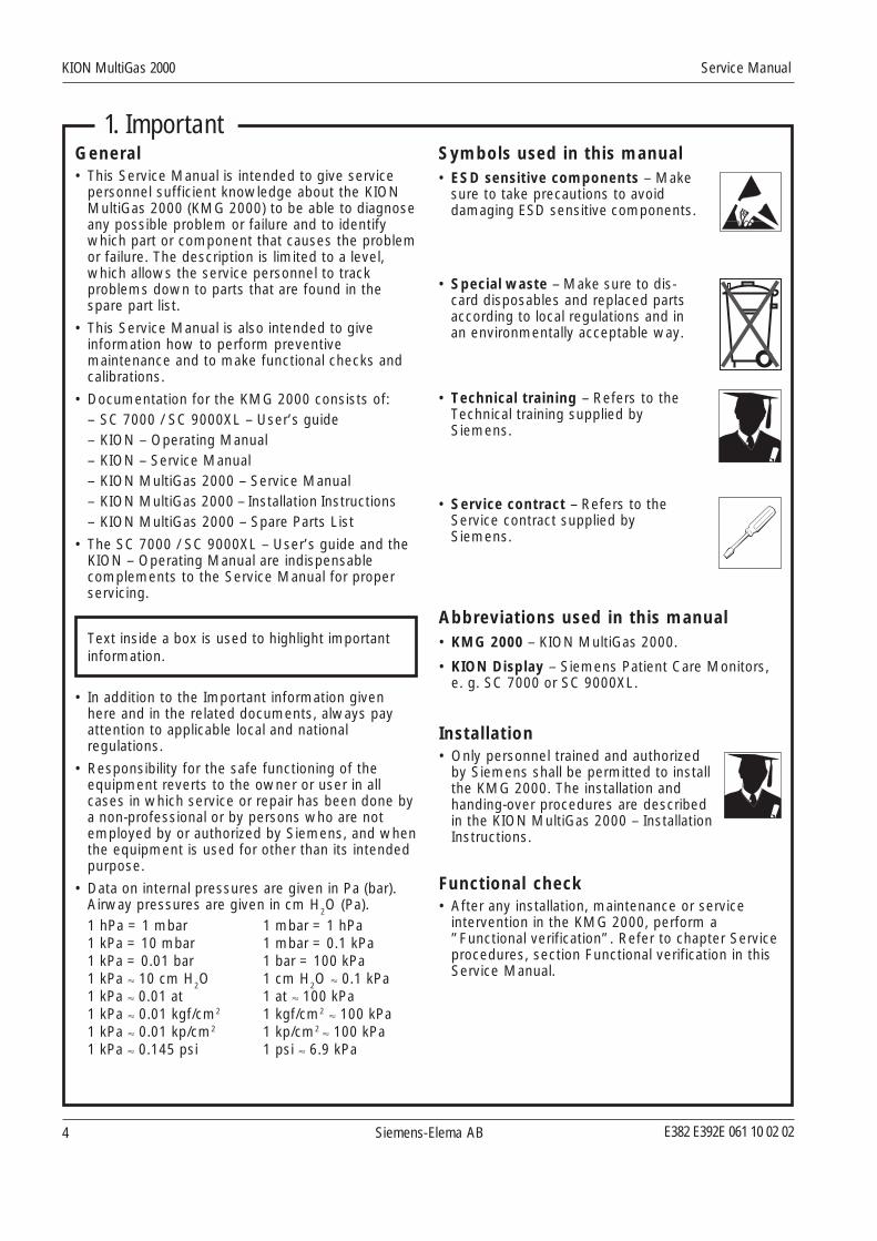
3.1 Water trapThe DRYLINE™ water trap protects the gas analyzersystem from condensed water, secretions, bacterialcontamination and dust. It consists of two parts, afilter housing with hydrophobic anti-bacterial filter anda container for separated waste.
The filter housing has one gas sample inlet to beconnected to the sampling tube.
In the water trap, the sampling flow is divided in twoparts:
• Sampling gas flow (approx. 90%).
• Purge gas flow (approx. 10%).
There are two outlets in the filter housing, one foreach gas flow.
The DRYLINE water trap to be used with theKMG 2000 is designed for a sampling flow of 120–200 ml/min. For further information, see Water trapreceptacle below.
3.2 Water trap receptacleThe water trap is connected to the water trapreceptacle. There are two gas connections on thereceptacle; one for the sampling gas flow and one forthe purge gas flow.
The two electrical switches on the water trapreceptacle detects if a water trap is present andidentifies the version of the connected water trap.The water trap receptacle is designed to identify twodifferent water trap versions:
• The high-flow water trap. This version of the watertrap is to be used with the KMG 2000. The watertrap activates both switches. The sampling flow isby default set to 200 ml/min, but can be changed to120 ml/min via the KION Display, refer to the User'smanual.
• The low-flow water trap. This version of the watertrap is not used in this application. It activates onlythe lower switch. This low-flow water trap is inten-ded to be used in applications where the samplinggas is not routed back to the patient circuit.
If no water trap is connected or if a water trapwithout container is connected, both switches areinactive. The pump, and thus the gas flow throughthe KMG 2000, is automatically stopped to preventcontamination.
The control signal cable from the water trapreceptacle PC board is connected to the SCM300 PCboard via connector P4a.
Gas sa
mple
10% 90%
MG
A-0
05X
Upperswitch
Lowerswitch
PC boardFlat cable
Purge inlet Sample inlet
MG
A-0
06X
Siemens-Elema AB
KION MultiGas 2000 Service Manual
E382 E392E 061 10 02 0210
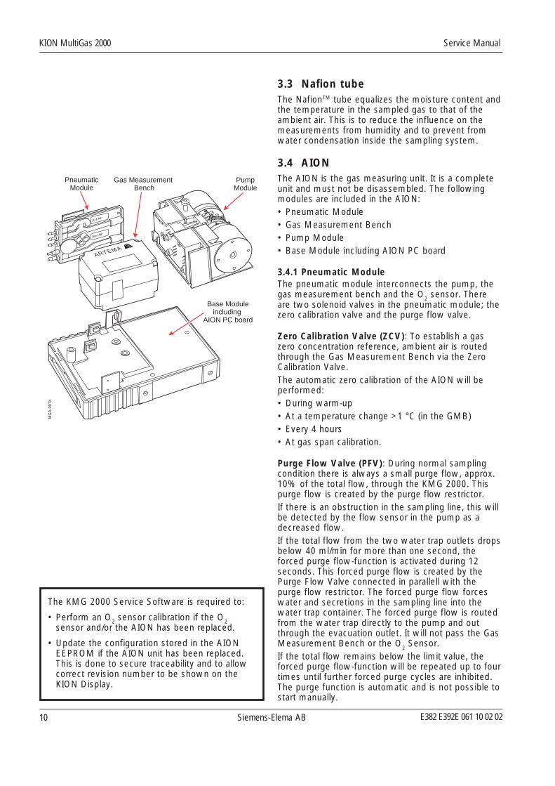
3.3 Nafion tubeThe NafionTM tube equalizes the moisture content andthe temperature in the sampled gas to that of theambient air. This is to reduce the influence on themeasurements from humidity and to prevent fromwater condensation inside the sampling system.
3.4 AIONThe AION is the gas measuring unit. It is a completeunit and must not be disassembled. The followingmodules are included in the AION:• Pneumatic Module• Gas Measurement Bench• Pump Module• Base Module including AION PC board
3.4.1 Pneumatic ModuleThe pneumatic module interconnects the pump, thegas measurement bench and the O
2 sensor. There
are two solenoid valves in the pneumatic module; thezero calibration valve and the purge flow valve.
Zero Calibration Valve (ZCV): To establish a gaszero concentration reference, ambient air is routedthrough the Gas Measurement Bench via the ZeroCalibration Valve.The automatic zero calibration of the AION will beperformed:• During warm-up• At a temperature change >1 °C (in the GMB)• Every 4 hours• At gas span calibration.
Purge Flow Valve (PFV): During normal samplingcondition there is always a small purge flow, approx.10% of the total flow, through the KMG 2000. Thispurge flow is created by the purge flow restrictor.If there is an obstruction in the sampling line, this willbe detected by the flow sensor in the pump as adecreased flow.If the total flow from the two water trap outlets dropsbelow 40 ml/min for more than one second, theforced purge flow-function is activated during 12seconds. This forced purge flow is created by thePurge Flow Valve connected in parallell with thepurge flow restrictor. The forced purge flow forceswater and secretions in the sampling line into thewater trap container. The forced purge flow is routedfrom the water trap directly to the pump and outthrough the evacuation outlet. It will not pass the GasMeasurement Bench or the O
2 Sensor.
If the total flow remains below the limit value, theforced purge flow-function will be repeated up to fourtimes until further forced purge cycles are inhibited.The purge function is automatic and is not possible tostart manually.
ARTEMA
Art.Nr.
Ser.Nr.
Gas Measurement Bench
Base Moduleincluding
AION PC board
PumpModule
MG
A-0
07X
PneumaticModule
The KMG 2000 Service Software is required to:
• Perform an O2 sensor calibration if the O2sensor and/or the AION has been replaced.
• Update the configuration stored in the AIONEEPROM if the AION unit has been replaced.This is done to secure traceability and to allowcorrect revision number to be shown on theKION Display.

E382 E392E 061 10 02 02 Siemens-Elema AB
Service Manual KION MultiGas 2000
11
Gasinlet
Gasoutlet
Infrared detector
Host interface
Signal processing
Measurement chamber
Lightsource
Filter wheel+ optical filter
MG
A-0
08X
3.4.2 Gas Measurement Bench
The CO2, N
2O and anesthetic agents are identified
and measured in the Gas Measurement Bench (GMB).
The GMB consists of an IR light source, a rotating filterwheel with optical filters connected to a DC motor, thegas measurement chamber and an IR light detector.
The measurement of CO2, N
2O and the anesthetic
agents in the sampling gas is based on the fact thatthe different gas components absorb infrared light atspecific wavelengths. The filter wheel has eightoptical filters to allow an accurate analysis of anymixture of these gases.
As O2 does not absorb infrared light to the same
extent as other breathing gases, O2 is measured bythe separate O
2 Sensor. However, the presence of O
2causes some interference and information from theO
2 Sensor is used to compensate for that interference.
The GMB also includes a PCB with a EEPROM andcomponents for pressure and temperaturemeasurements. Factory calibration data are stored inthe EEPROM and the gas calibration data is updatedduring the gas span calibration.
3.4.3 Pump Module
The double-action membrane pump has a built-in flowcontrol with its own flow sensor. The delivered flowis very stable with minimal flow variations. The designof the pump makes it very reliable with nomaintenance necessary.
The water trap to be used with the KMG 2000 setsthe default sampling flow rate to 200 ml/min. Thesampling flow rate can be changed to 120 ml/min viathe KION Display, refer to the User's manual.
During the forced purge flow, the pump capacity willbe increased to create the forced purge flow. This willnot change the sampling flow rate.
3.4.4 AION PC board
The AION module has a PC board with CPU andmemory functions. This PC board controls the gassampling system and performs calculations from themeasured parameters. The analog signals from theGMB and from the O2 sensor are converted to digitalsignals in the AION CPU.
The AION-SW, stored in a flash memory, can beupdated/upgraded. Refer to chapter Serviceprocedures, section Software installation.
The AION PC board has a 5 V DC/DC converter for itsinternal power supply and for O
2 sensor power supply.

Siemens-Elema AB
KION MultiGas 2000 Service Manual
E382 E392E 061 10 02 0212
Photo- detector
Light source
Feedback signal
Output: Voltageproportionalto O2 conc.
GND
Permanent magnets
Current proportionalto O2 conc
MG
A-0
09X
3.5 O2 sensorThe O2 sensor is a paramagnetic sensor that measuresthe O
2 content in the sampled gas mixture. The sensor
output is one volt for a concentration of 100% oxygen.
O2 is distinguished from most other common gasesby its paramagnetic properties. This fact is used bythe paramagnetic O
2 sensor, which has two nitrogen-
filled glass spheres mounted on a strong rare metaltaut-band suspension. This assembly is suspended ina symmetrical non-uniform magnetic field. In thepresence of paramagnetic O
2, the glass spheres are
pushed further away from the strongest part of themagnetic field. The strength of the torque acting onthe suspension is proportional to the O2concentration.
A feedback system creates a current that balancesthe torque acting on the suspension assembly. Thefeedback current is directly proportional to the partialpressure of O
2 in the sample. A voltage output is
derived that is proportional to the current, which inturn is proportional to the O
2 concentration.
The O2 sensor has no consumable parts and has a
consistent performance over time. It requires noreference gas for zero calibration and has nointerference from other respiratory gases.
The O2 sensor delivers analogue information to the
AION CPU via the P6/P5 connectors on SCM300 PCboard. The analogue information is converted todigital and delivered to KION, together with gasmeasurement information from AION.
AION uses the O2 concentration data to compensatefor the O
2 interference on the gas measurements
performed by AION.
The O2 sensor is powered with +5 VDC from AIONvia P5/P6 on SCM300 PC board.
The KMG 2000 Service Software is required to:
• Adjust the potentiometers on the O2 sensor.If the KMG 2000 Service Software is not used,the measurement accuracy of the KMG 2000will be outdated.
• Perform an O2 sensor calibration if the O2sensor and/or the AION has been replaced.
• Update the O2 sensor serial number stored in
AION EEPROM if the O2 sensor has beenreplaced.

E382 E392E 061 10 02 02 Siemens-Elema AB
Service Manual KION MultiGas 2000
13
AIONRS232
KIONRS232 CAN
SCM300PC board
AION
PrCCPU
KIONMGI
KIONDisplay
MGA-010X
P3 P1 P2 P4SW1 SW2
MG
A-0
11X
EVAC
P1, Software installation and service com. connectorNo. Name Source Description1 DGnd — Digital ground2 Vpos Host Positive power supply3 DataTd KMG AION transmit data4 Vpos Host Positive power supply.5 ServiceTd KMG AION and SCM service transmit data6 Vpos Host Positive power supply7 nc — No connection8 nc — No connection9 PGnd — Power ground10 DGnd — Digital ground11 PGnd — Power ground12 DataRd Host AION receive data13 PGnd — Power ground14 ServiceRd Host AION and SCM service receive data
P2, Power supply connectorNo. Name Source Description1 Vpos Host Positive power supply2 Vpos Host Positive power supply3 nc — No connection4 PGnd — Power ground5 PGnd — Power ground6 PGnd — Power ground7 PGnd — Power ground8 Vpos Host Positive power supply9 Vpos Host Positive power supply
P3, Monitor communication connectorNo. Name Source Description1 CanL Host & MGI Differential CAN-bus low line2 CanL Host & MGI Differential CAN-bus low line3 CanH Host & MGI Differential CAN-bus high line4 CanH Host & MGI Differential CAN-bus high line5 Gnd — Ground6 Td PrC RS232 Transmitted data7 Cts Host or MGI RS232 Clear to send8 Rts PrC RS232 Request to send9 Rd Host or MGI RS232 Received data10 nc — No connection11 TdLoop MGI RS232 Transmitted data (loop back)12 RtsLoop PrC RS232 Request to send (loop back)13 CtsLoop MGI RS232 Clear to send (loop back)14 RdLoop PrC RS232 Received data (loop back)15 nc — No connection
P4, Water trap receptacle connector1 Vwt – Positive voltage. Short circuit protected with 50 ohm.
Not used.2 Wt Type – Water trap type. Low Connection to ground for
high flow and open circuit for low flow.3 WtMounted – Water trap mounted. Connection to ground
when water trap mounted.4 DGnd – Digital ground
3.6 SCM300 PC boardThe electrical connectors and switches accessible onthe rear panel are mounted on the SCM300 PC board.The PC board is also an interconnection boardbetween AION, the O
2 sensor and the water trap
receptacle. For further information regarding connec-tors, refer to section Rear panel below and to theFunctional block diagram.
The KMG 2000 is powered by 24 V DC from the KIONpower supply. The SCM300 PC board has a 5 VDCvoltage converter for its internal electrical circuits.
The Protocol Converter PrC CPU on the SCM300 PCboard converts the gas measurement informationfrom the AION RS232 protocol to the RS232 protocolused in KION. The KION MGI (inside KION) convertsthe KION RS232 protocol to the CAN protocol usedby the KION Display.
The PrC-SW, stored in a flash memory, can beupdated/upgraded. Refer to chapter Serviceprocedures, section Software installation.
3.7 Rear panelThe rear panel of the KMG 2000 has the followingconnectors and switches:P1: Software and service communication
connector.P2: Power supply connector.P3: Monitor communication connector.P4: Water trap receptacle connector.SW1: Switch with integrated LED, used when
installing PrC-SW.SW2: Switch with integrated LED, used when
installing AION-SW.EVAC: Evacuation outlet connector for sampling gas.
The KMG 2000 Service Software is required to:
• Update the SCM300 H/W revision and S/Wversion stored in AION EEPROM if the SCM300board has been replaced.

Siemens-Elema AB
KION MultiGas 2000 Service Manual
E382 E392E 061 10 02 0214
4. Disassembly and assembly4.1 GeneralAll service associated with the KMG 2000, includingdisassembly and assembly, is done in accordancewith this Service Manual.
Only personnel trained and authorized bySiemens shall be permitted to performinstallation, service or maintenance of theKION and/or the KMG 2000.
4 .2 Handling PC boardsThe PC board contains components thatare highly sensitive to static electricity.Those who come into contact with circuitboards containing sensitive componentsmust take certain precautions to avoiddamaging the components (ESD protection).
When working with ESD sensitive componentsalways use a grounded wristband and grounded worksurface. Adequate service tools must also be used.PC boards (spare or exchange parts) must always bekept in protective packaging for sensitive electronicdevices.
PC boards must not be inserted or removed whilepower is applied to the PC boards.
Remove and insert the PC boards very carefully toavoid damage to the connectors.
4.3 Tools• Standard service tools
• Torx wrench size T6
• Knife / scalpel
E382 E392E 061 10 02 02 Siemens-Elema AB
Service Manual KION MultiGas 2000
15
MG
A-0
22X
Water trapreceptacle
cable
Cover plate
Samplinggas tube
Purgegas tube
Watertrap
receptacle
Watertrap
receptaclehousing
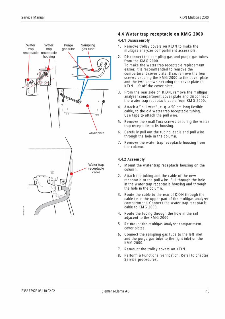
4.4 Water trap receptacle on KMG 20004.4.1 Disassembly
1. Remove trolley covers on KION to make themultigas analyzer compartment accessible.
2. Disconnect the sampling gas and purge gas tubesfrom the KMG 2000.To make the water trap receptacle replacementeasier, it is recommended to remove thecompartment cover plate. If so, remove the fourscrews securing the KMG 2000 to the cover plateand the two screws securing the cover plate toKION. Lift off the cover plate.
3. From the rear side of KION, remove the multigasanalyzer compartment cover plate and disconnectthe water trap receptacle cable from KMG 2000.
4. Attach a ”pull wire”, e. g. a 50 cm long flexiblecable, to the old water trap receptacle tubing.Use tape to attach the pull wire.
5. Remove the small Torx screws securing the watertrap receptacle to its housing.
6. Carefully pull out the tubing, cable and pull wirethrough the hole in the column.
7. Remove the water trap receptacle housing fromthe column.
4.4.2 Assembly
1. Mount the water trap receptacle housing on thecolumn.
2. Attach the tubing and the cable of the newreceptacle to the pull wire. Pull through the holein the water trap receptacle housing and throughthe hole in the column.
3. Route the cable to the rear of KION through thecable tie in the upper part of the multigas analyzercompartment. Connect the water trap receptaclecable to KMG 2000.
4. Route the tubing through the hole in the railadjacent to the KMG 2000.
5. Re-mount the multigas analyzer compartmentcover plates.
6. Connect the sampling gas tube to the left inletand the purge gas tube to the right inlet on theKMG 2000.
7. Remount the trolley covers on KION.
8. Perform a Functional verification. Refer to chapterService procedures.

Siemens-Elema AB
KION MultiGas 2000 Service Manual
E382 E392E 061 10 02 0216
MG
A-0
21X
Sampling gas tube
Purge gas tube
Cover plate
BracketBracket screw Bracket screw
RS232communication
cable
24 V DCpowercable
Evacuationtube
Water trapreceptacle
cable
4.5 Removal and installation ofKMG 2000 in KION
4.5.1 Removal
1. Remove trolley covers on KION to make themultigas analyzer compartment accessible.
2. Disconnect the sampling gas tube and purge gastube from the KMG 2000.
3. Remove the four screws securing the KMG 2000to the cover plate and the two screws securingthe cover plate to KION. Lift off the cover plate.
4. From the rear side of KION, remove the multigasanalyzer compartment cover plate.
5. Loosen the two bracket screws, remove thebracket and pull out the KMG 2000.
6. Disconnect the:– Water trap receptacle cable– Evacuation tube– RS232 communication cable– 24 V DC power cable.
7. Lift off the KMG 2000.
4.5.2 Assembly
1. Place the KMG 2000 in position in the multigasanalyzer compartment.
2. Connect the:– Water trap receptacle cable– Evacuation tube– RS232 communication cable– 24 V DC power cable.
3. Mount the bracket screws loosely.
4. Slide the KMG 2000 into correct position insidethe multigas analyzer compartment.
5. Mount the bracket. Do not tighten the bracketscrews yet.
6. Mount the cover plate:– Tighten the four screws securing the KMG 2000
to the cover plate.– Tighten the two screws securing the cover plate
to the KION.
7. Connect the sampling gas tube to the left inletand the purge gas tube to the right inlet on theKMG 2000.
8. On the rear side of KION:– Squeeze the KMG 2000 and the bracket
together and tighten the two bracket screws.– Mount the cover plate.
9. Remount the trolley covers on KION.
E382 E392E 061 10 02 02 Siemens-Elema AB
Service Manual KION MultiGas 2000
17
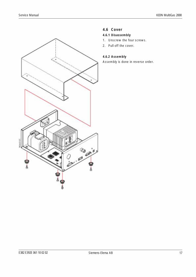
4.6 Cover4.6.1 Disassembly
1. Unscrew the four screws.
2. Pull off the cover.
4.6.2 Assembly
Assembly is done in reverse order.
Siemens-Elema AB
KION MultiGas 2000 Service Manual
E382 E392E 061 10 02 0218
O sensor2
AION
O2
1
2
4
3
5
MG
A-0
15X
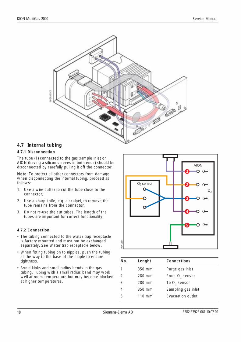
No. Lenght Connections
1 350 mm Purge gas inlet
2 280 mm From O2 sensor
3 280 mm To O2 sensor
4 350 mm Sampling gas inlet
5 110 mm Evacuation outlet
4.7 Internal tubing4.7.1 Disconnection
The tube (1) connected to the gas sample inlet onAION (having a silicon sleeves in both ends) should bedisconnected by carefully pulling it off the connector.
Note: To protect all other connectors from damagewhen disconnecting the internal tubing, proceed asfollows:
1. Use a wire cutter to cut the tube close to theconnector.
2. Use a sharp knife, e.g. a scalpel, to remove thetube remains from the connector.
3. Do not re-use the cut tubes. The length of thetubes are important for correct functionality.
4.7.2 Connection
• The tubing connected to the water trap receptacleis factory mounted and must not be exchangedseparately. See Water trap receptacle below.
• When fitting tubing on to nipples, push the tubingall the way to the base of the nipple to ensuretightness.
• Avoid kinks and small radius bends in the gastubing. Tubing with a small radius bend may workwell at room temperature but may become blockedat higher temperatures.
E382 E392E 061 10 02 02 Siemens-Elema AB
Service Manual KION MultiGas 2000
19
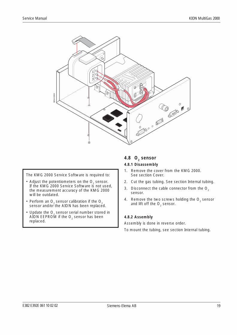
4.8 O2 sensor4.8.1 Disassembly
1. Remove the cover from the KMG 2000.See section Cover.
2. Cut the gas tubing. See section Internal tubing.
3. Disconnect the cable connector from the O2sensor.
4. Remove the two screws holding the O2 sensorand lift off the O
2 sensor.
4.8.2 Assembly
Assembly is done in reverse order.
To mount the tubing, see section Internal tubing.
The KMG 2000 Service Software is required to:
• Adjust the potentiometers on the O2 sensor.If the KMG 2000 Service Software is not used,the measurement accuracy of the KMG 2000will be outdated.
• Perform an O2 sensor calibration if the O2sensor and/or the AION has been replaced.
• Update the O2 sensor serial number stored inAION EEPROM if the O
2 sensor has been
replaced.
123
MG
A-0
16X

Siemens-Elema AB
KION MultiGas 2000 Service Manual
E382 E392E 061 10 02 0220
4.9 AION4.9.1 Disassembly
1. Remove the cover from the KMG 2000.See section Cover.
2. Remove the O2 sensor. See section O2 sensor.
3. Remove/cut the gas tubing. See section Internaltubing.
4. Disconnect the cable connector from SCM300 PCboard.
5. Loosen the two inner screws holding the AION.
6. Remove the two outer screws holding the AION.
6. Lift off AION.
4.9.2 Assembly
Assembly is done in reverse order.
To mount the tubing, see section Internal tubing.
The KMG 2000 Service Software is required to:
• Perform an O2 sensor calibration if the O2sensor and/or the AION has been replaced.
• Update the configuration stored in AIONEEPROM if the AION unit has been replaced.This is done to secure traceability and to allowcorrect revision number to be shown on theKION Display.

E382 E392E 061 10 02 02 Siemens-Elema AB
Service Manual KION MultiGas 2000
21
4.10 SCM300 PC board with connectors4.10.1 Disassembly
1. Remove the cover from the KMG 2000.See section Cover.
2. Remove the two screws on the rear panel holdingthe metal shield and lift off the metal shield.
3. Disconnect the two flat cable connectors from theSCM300 PC board.
4. Remove the five screws holding the SCM300 PCboard.
5. Lift off the SCM300 PC board.
4.10.2 Assembly
Assembly is done in reverse order.
The KMG 2000 Service Software is required to:
• Update the SCM300 H/W revision and S/Wversion stored in AION EEPROM if the SCM300board has been replaced.
123
MG
A-0
18X

Siemens-Elema AB
KION MultiGas 2000 Service Manual
E382 E392E 061 10 02 0222
5. Service procedures5.1 Functional verificationAfter any installation, maintenance or serviceintervention in the KMG 2000, perform a:
1. Leakage check
2. Gas measurement check.
If the KMG 2000 should fail in any of these checks,remedy the cause and repeat the test. The functionalverification checks must be passed before the KMG2000 can be released for clinical use.
5.2 Software installationThe following softwares can be downloaded in theflash memories via the connector P1:
• Protocol Converter Software (PrC-SW).
• Gas Analyzer Software (AION-SW)
5.2.1 Tools
• Download program (Hitachi™ FLASH DevelopmentTool kit). Included on the Software upgrade CD-ROM.
• TTY terminal software (e. g. HyperTerminal) on PC.
• Service cable (Siemens Order No. 47 14 346 E536U).
5.2.2 Parts
• Software upgrade CD-ROM including downloadprogram.
• Software version label (sticker).
5.2.3 FLASH Development Tool kit
• For installation, refer to information stored on theSoftware upgrade CD-ROM.
• For details about the FLASH Development Tool kit,see its built-in manual.
5.2.4 Preparation
1. Connect the service cable between P1 on rearpanel and the serial (COM) port on the PC.
2. Set the KION to Standby and start the PC.
5.2.5 Protocol Converter Software (PrC-SW)
1. Push SW1 on the rear panel. LED lights up.
2. Start the download program.
3. In the FLASH Development Toolkit window,select File menu, item Open and load theSCM_V_X_X.MOT included on the CD.
4. Select Image menu, item Download image.
5. In the FLASH Controller window Connectionpanel, set:
– Select Interface = Direct Connection.
– Select processor SH/7044F in Device selection.
– Select appropriate COM port.
– Set baud rate to 19200.
– Select Connection = BOOT Mode.
6. Click on Connect under commands and wait untilcommunication is established and verified with”Connection complete”.If communication cannot be established, reducebaud rate to 9600 (or lower) and repeat step 6.
7. Click on Download file. The download starts andwill continue several minutes.
8. Make sure that the download is verified with”Image successfully written to device”.
9. Switch off the PC and disconnect the servicecable.
Restart KION before use.
E382 E392E 061 10 02 02 Siemens-Elema AB
Service Manual KION MultiGas 2000
23
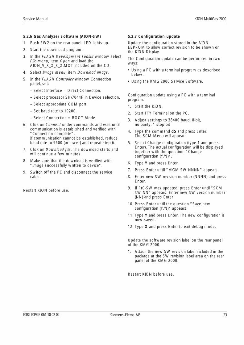
5.2.7 Configuration update
Update the configuration stored in the AIONEEPROM to allow correct revision to be shown onthe KION Display.
The Configuration update can be performed in twoways:
• Using a PC with a terminal program as describedbelow.
• Using the KMG 2000 Service Software.
Configuration update using a PC with a terminalprogram:
1. Start the KION.
2. Start TTY Terminal on the PC.
3. Adjust settings to 38400 baud, 8-bit,no parity, 1 stop bit
4. Type the command d5 and press Enter.The SCM Menu will appear.
5. Select Change configuration (type 1 and pressEnter). The actual configuration will be displayedtogether with the question: “Changeconfiguration (Y/N)”.
6. Type Y and press Enter.
7. Press Enter until “MGM SW NNNN” appears.
8. Enter new SW revision number (NNNN) and pressEnter.
9. If PrC-SW was updated; press Enter until “SCMSW NN” appears. Enter new SW version number(NN) and press Enter
10. Press Enter until the question “Save newconfiguration (Y/N)” appears.
11. Type Y and press Enter. The new configuration isnow saved.
12. Type X and press Enter to exit debug mode.
Update the software revision label on the rear panelof the KMG 2000.
1. Attach the new SW revision label included in thepackage at the SW revision label area on the rearpanel of the KMG 2000.
Restart KION before use.
5.2.6 Gas Analyzer Software (AION-SW)
1. Push SW2 on the rear panel. LED lights up.
2. Start the download program.
3. In the FLASH Development Toolkit window selectFile menu, item Open and load theAION_V_X_X_X_X.MOT included on the CD.
4. Select Image menu, item Download image.
5. In the FLASH Controller window Connectionpanel, set:
– Select Interface = Direct Connection.
– Select processor SH/7044F in Device selection.
– Select appropriate COM port.
– Set baud rate to 19200.
– Select Connection = BOOT Mode.
6. Click on Connect under commands and wait untilcommunication is established and verified with”Connection complete”.If communication cannot be established, reducebaud rate to 9600 (or lower) and repeat step 6.
7. Click on Download file. The download starts andwill continue a few minutes.
8. Make sure that the download is verified with”Image successfully written to device”.
9. Switch off the PC and disconnect the servicecable.
Restart KION before use.

Siemens-Elema AB
KION MultiGas 2000 Service Manual
E382 E392E 061 10 02 0224
5.3 Calibrations and verifications5.3.1 Recommended Tools and Equipment
• KION including KION Display (e.g. SC 7000 orSC 9000XL).
• Calibration gas kit including gas bottle, regulator andtubing. Siemens Order No. 52 07 415 E536U.
• Gas evacuation system for the calibration gas.
• Flowmeter, 0–400 sml/min with ±1.5% accuracy orbetter. Recommended: Sierra Flow Control model822-CE-RFQ-1801.
• Standard service tools:
– Screwdriver
– Wire cutter and needle nose plier.
Cal
ibra
tion
gas
MG
A-0
19X
Samplingtube
Calibration tube incl.valve and collector bag
Room air
Calibration setup
5.3.2 Calibration setup
The calibration gas kit is required for the:
• Gas measurement check
• Gas span calibration
• Zero calibration valve check.
Warning: The calibration gas contains substancesthat may be detrimental to your health. During use ofcalibration gas, assure that the KMG 2000 is connec–ted to an effective gas evacuation system, e.g. thehospital’s EVAC system.
During calibration of the KMG 2000, differentsampling flows are used (70 – 200 ml/min). This isautomatically controlled by the KMG 2000. As theflow regulator on the calibration gas bottle is set toapprox. 150 ml/min, the collector bag must be usedas a gas reservoir to ensure sufficient calibration gassupply to the KMG 2000.
Supply calibration gas to the system as follows:
1. Connect the calibration gas equipment to thesampling tube as shown in the illustration.Note: Make sure that the 3-way-valve on thecalibration tube is set to ”room air”.
2. Carefully open the calibration gas bottle valve tofill the collector bag with calibration gas.Note: Fill the collector bag carefully. The bag willnot withstand high gas pressure.
3. When sufficient amount of calibration gas iscollected in the bag, switch the 3-way-valve onthe calibration tube to ”calibration gas”.
4. The calibration gas from the collector bag will nowbe supplied to the system. Adjust the calibrationgas bottle valve to keep a sufficient amount ofcalibration gas in the collector bag during thecalibration procedure.
5. When the calibration is completed, close thecalibration gas bottle valve.
6. Allow the KMG 2000 to purge the gas in thecalibration setup, including the collection bag,into the gas evacuation system.
7. Set the 3-way-valve to ”room air”.
8. Remove the calibration gas kit.
E382 E392E 061 10 02 02 Siemens-Elema AB
Service Manual KION MultiGas 2000
25
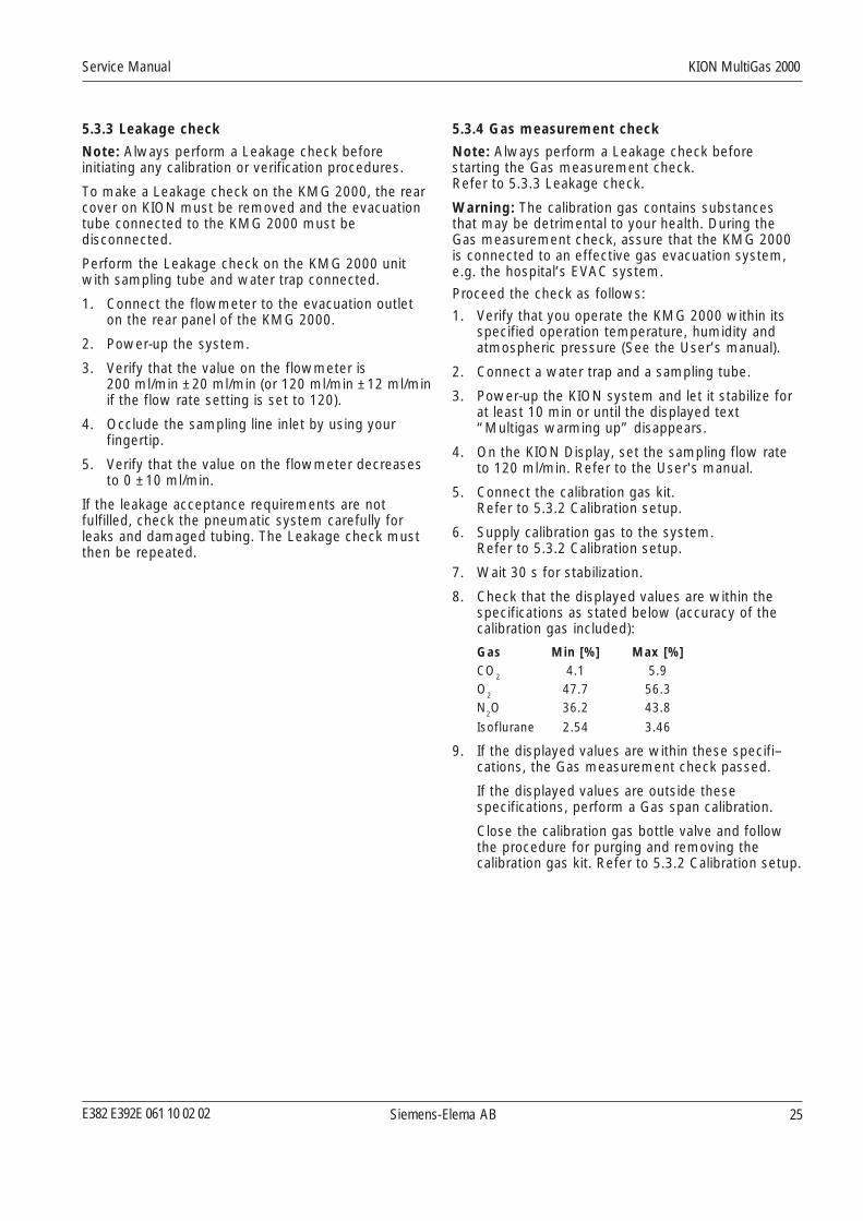
5.3.4 Gas measurement check
Note: Always perform a Leakage check beforestarting the Gas measurement check.Refer to 5.3.3 Leakage check.
Warning: The calibration gas contains substancesthat may be detrimental to your health. During theGas measurement check, assure that the KMG 2000is connected to an effective gas evacuation system,e.g. the hospital’s EVAC system.
Proceed the check as follows:
1. Verify that you operate the KMG 2000 within itsspecified operation temperature, humidity andatmospheric pressure (See the User’s manual).
2. Connect a water trap and a sampling tube.
3. Power-up the KION system and let it stabilize forat least 10 min or until the displayed text“Multigas warming up” disappears.
4. On the KION Display, set the sampling flow rateto 120 ml/min. Refer to the User's manual.
5. Connect the calibration gas kit.Refer to 5.3.2 Calibration setup.
6. Supply calibration gas to the system.Refer to 5.3.2 Calibration setup.
7. Wait 30 s for stabilization.
8. Check that the displayed values are within thespecifications as stated below (accuracy of thecalibration gas included):
Gas Min [%] Max [%]CO
24.1 5.9
O2 47.7 56.3N
2O 36.2 43.8
Isoflurane 2.54 3.46
9. If the displayed values are within these specifi–cations, the Gas measurement check passed.
If the displayed values are outside thesespecifications, perform a Gas span calibration.
Close the calibration gas bottle valve and followthe procedure for purging and removing thecalibration gas kit. Refer to 5.3.2 Calibration setup.
5.3.3 Leakage check
Note: Always perform a Leakage check beforeinitiating any calibration or verification procedures.
To make a Leakage check on the KMG 2000, the rearcover on KION must be removed and the evacuationtube connected to the KMG 2000 must bedisconnected.
Perform the Leakage check on the KMG 2000 unitwith sampling tube and water trap connected.
1. Connect the flowmeter to the evacuation outleton the rear panel of the KMG 2000.
2. Power-up the system.
3. Verify that the value on the flowmeter is200 ml/min ±20 ml/min (or 120 ml/min ±12 ml/minif the flow rate setting is set to 120).
4. Occlude the sampling line inlet by using yourfingertip.
5. Verify that the value on the flowmeter decreasesto 0 ±10 ml/min.
If the leakage acceptance requirements are notfulfilled, check the pneumatic system carefully forleaks and damaged tubing. The Leakage check mustthen be repeated.
Siemens-Elema AB
KION MultiGas 2000 Service Manual
E382 E392E 061 10 02 0226
5.3.5 Zero calibration valve check
Note: Always perform a Leakage check beforestarting the Zero calibration valve check.Refer to 5.3.3 Leakage check.
Warning: The calibration gas contains substancesthat may be detrimental to your health. During theZero calibration valve check, assure that the KMG2000 is connected to an effective gas evacuationsystem, e.g. the hospital’s EVAC system.
Proceed as follows:
1. Verify that you operate the KMG 2000 within itsspecified operation temperature, humidity andatmospheric pressure (refer to the KION DisplayUser’s manual).
2. Connect a water trap and a sampling tube.
3. Power-up the KION system and let it stabilize forat least 10 min or until the displayed message“Multigas warming up” disappears.
4. Connect the calibration gas kit.Refer to 5.3.2 Calibration setup.
5. On the KION Display, access Service menu andenter Biomed password (4712). Refer to the KIONDisplay User's manual.
6. Select Calibration
7. Supply calibration gas to the system.Refer to 5.3.2 Calibration setup.
8. Wait 15 s for stabilization.
9. Select MGM Calibration
10. Wait for message “Multigas zero accepted”
11. Press the Main Screen key to abort the calibrationsequence.
12. Verify that the displayed values are within thespecifications stated below (this includes theaccuracy of the calibration gas):
Gas Min [%] Max [%]CO
24.1 5.9
O2
47.7 56.3N2O 36.2 43.8
Isoflurane 2.54 3.46
13. If the displayed values are within these specifi–cations, the Zero calibration valve check passed.
If the displayed values are outside thesespecifications, the Zero calibration valve checkfailed. Replace the AION.
Close the calibration gas bottle valve and followthe procedure for purging and removing thecalibration gas kit. Refer to 5.3.2 Calibration setup.
5.3.6 Gas span calibration
This procedure must be performed only if the Gasmeasurement check shows that the unit is outsidethe gas measurement specifications.
During Gas span calibration, a calibration gas withaccurately known gas concentrations is introducedinto the KMG 2000 gas sampling system. If there aredifferences between the measured and expectedvalues, span calibration factors are stored in the AIONEEPROM and the measured values will be compen-sated by these factors.
Note: Always perform a Leakage check beforestarting the Gas span calibration. Refer to 5.3.3Leakage check.
Warning: The calibration gas contains substancesthat may be detrimental to your health. During theGas span calibration, assure that the KMG 2000 isconnected to an effective gas evacuation system,e.g. the hospital’s EVAC system.
Proceed as follows:1. Verify that you operate the KMG 2000 within its
specified operation temperature, humidity andatmospheric pressure (refer to the KION DisplayUser’s manual).
2. Connect a water trap and a sampling tube.3. Power-up the KION system and let it stabilize for
at least 10 min or until the displayed message“Multigas warming up” disappears.
4. Connect the calibration gas kit. Refer to 5.3.2Calibration setup.
5. On the KION Display, set the sampling flow rateto 120 ml/min. Refer to the KION Display User'smanual.
6. On the KION Display, select the Agent parameterbox to bring up the Agent menu. Refer to theKION Display User’s manual.
7. Check that ID Override is set to OFF.8. Access Service menu and enter Biomed
password (4712).9. Select MultiGas (MGM) Calibration.
Note: The path to select MGM calibration differsbetween the KION Display software versions.
10. When message “Supply Gas Mixture and thenPress Continue” displays, supply calibration gasto the system. Refer to 5.3.2 Calibration setup.
11. Wait 30 s for stabilization.12. Select ”Continue”.13. Wait for the message “PASS”. The calibration is
finished.14. Press the Main Screen key to return to the main
screen.15. Close the calibration gas bottle valve and follow
the procedure for purging and removing thecalibration gas kit. Refer to 5.3.2 Calibration setup.

E382 E392E 061 10 02 02 Siemens-Elema AB
Service Manual KION MultiGas 2000
27
5.3.7 Gas zero calibration
Gas zero calibration of the KMG 2000 is automaticallyperformed by the Zero calibration valve. For furtherinformation, refer to chapter ”Description offunctions”, section ”AION”.
5.3.8 O2 sensor calibration
As the O2 sensor is flow-sensitive, the AION and theO
2 sensor must be calibrated together. The O
2 sensor
calibration must be carried out when either of the twounits are replaces.
The O2 sensor calibration requires KMG 2000 Service
Software.
5.4 KMG 2000 Service SoftwareThe KMG 2000 Service Software, run on a PCconnected to the KMG 2000, will enable a number ofservice and troubleshooting options.
The KMG 2000 Service Software will e. g. display:
• Status for the different sub-units
• Error logs
• Error log frequency
• Messages from the KMG 2000.
The KMG 2000 Service Software is required to:
• Update the configuration stored in the AIONEEPROM if the AION unit has been replaced.This is done to secure traceability and to allowcorrect revision number to be shown on the KIONDisplay.
• Perform an O2 sensor calibration if the O2 sensorand/or the AION has been replaced.
• Adjust the potentiometers on the O2 sensor.If the KMG 2000 Service Software is not used, themeasurement accuracy of the KMG 2000 will beoutdated.
• Update the O2 sensor serial number stored in AION
EEPROM if the O2 sensor has been replaced.
• Update the SCM300 H/W revision and S/W versionstored in AION EEPROM if the SCM300 board hasbeen replaced.
Instructions for the KMG 2000 Service Software isincluded in the software package.
Siemens-Elema AB
KION MultiGas 2000 Service Manual
E382 E392E 061 10 02 0228
6. Troubleshooting6.1 GeneralBefore you start any troubleshooting, begin if possibleby questioning the person reporting the fault. Askhow the fault appeared.
Make sure that there has been no operating error.
There should be a logical trend to your trouble-shooting. First try to trace the faulty function. Thenthe most suitable procedure is to track down theexact fault by systematically replacing individual spareparts, one at a time.
One purpose of the Description of functions and theDiagrams in this Service Manual is to make it easierto trace faults.
Before any KION or KMG 2000 cover is removed,make sure that the mains power supply isdisconnected.
With mains power supply connected to the unit,there are energized electrical components insidethe equipment. All personnel must exerciseextreme caution when in the vicinity of thisequipment if fault tracing or adjustments areperformed with mains power supply connectedand covers removed.
After any service intervention in the KION System,perform a Function check according to instructionsin the Operating Manual.
6.2 Problem identificationTechnical problems with the KMG 2000 can bedivided in two main groups:
• No communication established between the KIONDisplay and the KMG 2000. Troubleshooting isdescribed in section 6.4 Communication.
• Problem with the information created by the KMG2000 (wrong CO2, O2 or agent concentration, longrise or response time, message ”MultiGas datainvalid” on the KION Display). Troubleshooting isdescribed in section 6.5 Inaccurate information.
6.3 Prior to troubleshootingPrior to any troubleshooting:
1. Check that the sampling line and the water trapare correctly mounted.
2. Check that the sampling gas tube, the purge gastube and the evacuation tube are correctlyconnected to the KMG 2000.
6.4 CommunicationSet the KION to Standby and wait until the text “KMG2000 Warming Up” is displayed on the KION Display.
Check if communication between the KION Displayand the KMG 2000 is established as follows:
1. Remove the water trap. Check that the message”MultiGas data invalid” appears on the KIONDisplay.
2. Connect the water trap. Check that the message”MultiGas data invalid” disappears on the KIONDisplay.
If communication is not established, proceed asfollows and repeat the communication test after eachaction:
3. Check the electrical connection between thewater trap receptacle and the KMG 2000. If anextra water trap receptacle is available, connect itto the KMG 2000 and repeat the communicationtests. Replace the water trap receptacle ifnecessary.
4. Check the RS232 communication between theKMG 2000 and the KION Display.Check connectors, cables, etc.
5. Check the power supply to the KMG 2000.Check connectors, cables, etc.
6. Check electrical connections inside the KMG 2000.Replace cables if necessary.
7. Replace the SCM300 PCBoard.KMG 2000 Service Software is required.
8. Replace the AION.KMG 2000 Service Software is required.

E382 E392E 061 10 02 02 Siemens-Elema AB
Service Manual KION MultiGas 2000
29
6.5 Inaccurate information6.5.1 Leakage
1. Perform a Leakage check, refer to chapter”Service procedures”.
If the Leakage check passed, go to section 6.5.2 Gasmeasurement.
If the Leakage check failed, proceed as follows andrepeat the Leakage check after each action:
2. Replace the water trap and the sampling line
3. If an extra water trap receptacle is available,connect it to the KMG 2000 and repeat theLeakage check. Replace the water trap receptacleif necessary.
4. Check all internal tubings inside the KMG 2000.Replace tubings if necessary.
5. Replace the AION.KMG 2000 Service Software is required.
6. Replace the O2 Sensor.KMG 2000 Service Software is required.
6.5.2 Gas measurement
1. Perform a Gas measurement check, refer tochapter ”Service procedures”.
If the Gas measurement check passed, the system isfunctional and no further troubleshooting is necessary.
If the Gas measurement check failed, go to section6.5.3 Gas span.
6.5.3 Gas span
1. Perform a Gas span calibration, refer to chapter”Service procedures”.
If the Gas span calibration passed, the system isfunctional and no further troubleshooting is necessary.
If the Gas span calibration failed, proceed as followsand repeat the Gas span calibration after each action:
2. Replace the AION.KMG 2000 Service Software is required.
3. Replace the O2 Sensor.
KMG 2000 Service Software is required.
7. Preventive maintenanceThe KMG 2000 must be serviced at regular intervalsby personnel trained and authorized by Siemens.Any maintenance or service must be noted in a logbook.
Preventive maintenance must be performed at leastonce every year as long as the unit is not used morethan normal. Normal operation is estimated tocorrespond to approx. 5.000 hours of operation.
As the KMG 2000 is an integrated part of the KIONSystem, preventive maintenance of the KMG 2000and the KION should be performed at the same time.
It is recommended that maintenance and service isdone as a part of a service contract with Siemens.
7.1 Performing the Preventivemaintenance
• Replace the water trap receptacle including tubing.Refer to chapter Disassembly and assembly.
• Replace the water trap and sampling line.
• Perform a Leakage test. Refer to chapter ”Serviceprocedures”.
• Perform a Gas measurement check. Refer tochapter ”Service procedures”.
• Perform a Zero Calibration Valve test. Refer tochapter ”Service procedures”.
• A Pre-use check of the KION System must beperformed before connecting the system to apatient.

Siemens-Elema AB
KION MultiGas 2000 Service Manual
E382 E392E 061 10 02 0230
Notes

E382 E392E 061 10 02 02 Siemens-Elema AB
Service Manual KION MultiGas 2000
31
Drivers
EEPROM
AION-SW
AIONCPU
GMB
P5b
P5a
P6a
P4a
P6b
P2
P1
P3
24VDC
24V
DC
PrCCPU
SCM300PC BOARD
AION PC BOARD
O2 SENSOR
WATER TRAP RECEPTACLE
90%
10%
WATER TRAP
DC DC
AION
PUMPZCV
PNEUMATICMODULE
SW
2S
W1
PrC-SW
DC DC
PFV
NAFIONTUBE
2
3
1
O2 O2 EVACUATIONOUTLET
RE
AR
PA
NE
L
P4b
MG
A-0
04X
8. Diagrams8.1 Functional block diagram

KION MultiGas 2000 – Service ManualOrder No.: 65 43 040 E392E
Printed in SwedenPrice group: 7
11022nd English edition,
November 2002
© Siemens-Elema AB, Electromedical Systems Division, 2001-2002. All rights reserved. No part of this publicationmay be reproduced, stored in a retrieval system, or transmitted in any form or by any means, electronic,mechanical, photocopying, recording, or otherwise, without the prior permission of the copyright owner in writing.Subject to alterations without prior notice.Issued by Siemens-Elema AB, Electromedical Systems Division, SE-171 95 Solna, Sweden.
E382 E392E 061 10 02 02


![[ MULTIGAS DETECTOR ] [ MULTIGAS DETEKTOR ]](https://img.pdfslide.us/doc/110x75/62d95fa13fc36f6d5025a20c/-multigas-detector-multigas-detektor-.jpg)