Embed Size (px)
Citation preview
Kintex-7 FPGA KC705 Embedded Kit
Getting Started Guide
Vivado Design Suite 2013.2
UG913 (v4.1.1) March 7, 2014
0402910-03
KC705 Getting Started Guide www.xilinx.com UG913 (v4.1.1) March 7, 2014
The information disclosed to you hereunder (the “Materials”) is provided solely for the selection and use of Xilinx products. To the maximum extent permitted by applicable law: (1) Materials are made available "AS IS" and with all faults, Xilinx hereby DISCLAIMS ALL WARRANTIES AND CONDITIONS, EXPRESS, IMPLIED, OR STATUTORY, INCLUDING BUT NOT LIMITED TO WARRANTIES OF MERCHANTABILITY, NON-INFRINGEMENT, OR FITNESS FOR ANY PARTICULAR PURPOSE; and (2) Xilinx shall not be liable (whether in contract or tort, including negligence, or under any other theory of liability) for any loss or damage of any kind or nature related to, arising under, or in connection with, the Materials (including your use of the Materials), including for any direct, indirect, special, incidental, or consequential loss or damage (including loss of data, profits, goodwill, or any type of loss or damage suffered as a result of any action brought by a third party) even if such damage or loss was reasonably foreseeable or Xilinx had been advised of the possibility of the same. Xilinx assumes no obligation to correct any errors contained in the Materials or to notify you of updates to the Materials or to product specifications. You may not reproduce, modify, distribute, or publicly display the Materials without prior written consent. Certain products are subject to the terms and conditions of Xilinx’s limited warranty, please refer to Xilinx’s Terms of Sale which can be viewed at http://www.xilinx.com/legal.htm#tos; IP cores may be subject to warranty and support terms contained in a license issued to you by Xilinx. Xilinx products are not designed or intended to be fail-safe or for use in any application requiring fail-safe performance; you assume sole risk and liability for use of Xilinx products in such critical applications, please refer to Xilinx’s Terms of Sale which can be viewed at http://www.xilinx.com/legal.htm#tos.
AUTOMOTIVE APPLICATIONS DISCLAIMERXILINX PRODUCTS ARE NOT DESIGNED OR INTENDED TO BE FAIL-SAFE, OR FOR USE IN ANY APPLICATION REQUIRING FAIL-SAFE PERFORMANCE, SUCH AS APPLICATIONS RELATED TO: (I) THE DEPLOYMENT OF AIRBAGS, (II) CONTROL OF A VEHICLE, UNLESS THERE IS A FAIL-SAFE OR REDUNDANCY FEATURE (WHICH DOES NOT INCLUDE USE OF SOFTWARE IN THE XILINX DEVICE TO IMPLEMENT THE REDUNDANCY) AND A WARNING SIGNAL UPON FAILURE TO THE OPERATOR, OR (III) USES THAT COULD LEAD TO DEATH OR PERSONAL INJURY. CUSTOMER ASSUMES THE SOLE RISK AND LIABILITY OF ANY USE OF XILINX PRODUCTS IN SUCH APPLICATIONS.
© Copyright 2012–2014 Xilinx, Inc. Xilinx, the Xilinx logo, Artix, ISE, Kintex, Spartan, Virtex, Vivado, Zynq, and other designated brands included herein are trademarks of Xilinx in the United States and other countries. All other trademarks are the property of their respective owners.
Revision HistoryThe following table shows the revision history for this document.
Date Version Revision
05/23/2012 1.0 Initial Xilinx release.
05/31/2012 1.0.1 Updated PDF document properties.
08/16/2012 1.1 Replaced ISE software with Xilinx Design Tools throughout. Added Vivado tools to KC705 Embedded Kit Contents, page 7. Updated URL for Kintex-7 FPGA embedded kit in What’s Available Online, page 8. Updated Figure 1-1, Figure 1-4, Figure 1-5, Figure 1-7, and Figure 1-8. Updated steps in Running the Video Demonstration, page 11. Updated Next Steps, page 18. Updated Table 1-1. Added Documentation, page 19. Updated title of Appendix B, Installation and Licensing of Xilinx Design Tools.
10/31/2012 1.2 Removed mention of flash drives throughout. Added jumper settings to step of Video Demonstration Hardware Setup Instructions, page 10. In step 3 of Running the Video Demonstration, page 11, changed 14.1 to 14.x.
11/27/2012 1.2.1 Updated XPN number on the title page.
01/24/2013 2.0 Updated jumper settings in step of Video Demonstration Hardware Setup Instructions. Added “(ISE Design Suite 14.4)” to document title.
04/12/2013 2.0.1 Removed XPN number from the title page. No other changes.
04/12/2013 3.0 Updated for ISE® Design Suite 14.5. Two of the local cores, DVI2AXI and PERF_MONITOR, were replaced with EDK build IPs. Figure 1-1 was updated and different color codes are used to differentiate local and EDK IPs. Figure 1-5 was updated. Appendixes were re-sequenced and Appendix C was enhanced.
04/17/2013 3.0.1 Updated links for UG914 and UG915.
04/23/2013 3.0.2 Updated links for UG914 and UG915.
UG913 (v4.1.1) March 7, 2014 www.xilinx.com KC705 Getting Started Guide
08/29/2013 4.0 Updated for Vivado Design Suite 2013.2. Updated Figure 1-1 and Figure 1-8. Updated Table 1-1.
12/20/2013 4.1 Updated disclaimer and copyright. Updated What’s Inside the Box.
03/07/2014 4.1.1 Made typographical edits.
Date Version Revision
KC705 Getting Started Guide www.xilinx.com 5UG913 (v4.1.1) March 7, 2014
Revision History . . . . . . . . . . . . . . . . . . . . . . . . . . . . . . . . . . . . . . . . . . . . . . . . . . . . . . . . . . . . . 2
Chapter 1: Getting Started with the Kintex-7 FPGA KC705 Embedded Kit
Introduction . . . . . . . . . . . . . . . . . . . . . . . . . . . . . . . . . . . . . . . . . . . . . . . . . . . . . . . . . . . . . . . . . 7KC705 Embedded Kit Contents . . . . . . . . . . . . . . . . . . . . . . . . . . . . . . . . . . . . . . . . . . . . . . 7Getting Started with the Video Demonstration . . . . . . . . . . . . . . . . . . . . . . . . . . . . . . . . . 8Running the Video Demonstration . . . . . . . . . . . . . . . . . . . . . . . . . . . . . . . . . . . . . . . . . . 11Running BIST tests . . . . . . . . . . . . . . . . . . . . . . . . . . . . . . . . . . . . . . . . . . . . . . . . . . . . . . . . 17
Next Steps . . . . . . . . . . . . . . . . . . . . . . . . . . . . . . . . . . . . . . . . . . . . . . . . . . . . . . . . . . . . . . . . . . 18
Appendix A: Communicating with the KC705 USB-UARTInstalling the USB-UART Driver . . . . . . . . . . . . . . . . . . . . . . . . . . . . . . . . . . . . . . . . . . . . 21
Appendix B: Installation and Licensing of Xilinx Design ToolsGetting Help and Support . . . . . . . . . . . . . . . . . . . . . . . . . . . . . . . . . . . . . . . . . . . . . . . . . . . 23
Appendix C: Additional ResourcesXilinx Resources . . . . . . . . . . . . . . . . . . . . . . . . . . . . . . . . . . . . . . . . . . . . . . . . . . . . . . . . . . . . 25Solution Centers . . . . . . . . . . . . . . . . . . . . . . . . . . . . . . . . . . . . . . . . . . . . . . . . . . . . . . . . . . . . 25Further Resources . . . . . . . . . . . . . . . . . . . . . . . . . . . . . . . . . . . . . . . . . . . . . . . . . . . . . . . . . . . 25
Appendix D: Warranty
Table of Contents
KC705 Getting Started Guide www.xilinx.com 7UG913 (v4.1.1) March 7, 2014
Chapter 1
Getting Started with the Kintex-7 FPGA KC705 Embedded Kit
IntroductionThe Kintex®-7 FPGA embedded kit conveniently delivers the key components of the Xilinx® Embedded Targeted Design Platform (TDP) required for developing embedded software and hardware in a wide range of applications in the broadcast, industrial, medical, and aerospace and defense markets. For software developers, a familiar Eclipse-based integrated development environment (IDE), GNU tools, operating systems, libraries, and a pre-verified reference design enables them to start programming right away. Similarly, hardware designers now have immediate access to a pre-integrated MicroBlaze™ processor subsystem that includes the most commonly used peripheral IP cores, enabling the designers to begin at once developing their custom logic.
This getting started guide identifies the steps required to set up the KC705 board and run the out-of-box video demonstration, which illustrates the flexibility and capability of a MicroBlaze processor subsystem for embedded design. If the Xilinx Design Tools have not already been installed, the user is directed through the steps to install the software, get updates, and generate a license.
KC705 Embedded Kit Contents
What’s Inside the Box
• KC705 evaluation board featuring the XC7K325T-2FFG900C FPGA
• USB cables, Ethernet cable, and universal power supply
• SD card
• Xilinx Design Tools (node-locked, device-locked for the XC7K325T-2FFG900C FPGA), which includes:
• Vivado® design tools
• Software Development Kit (SDK)
• Documentation:
• Kintex-7 FPGA Embedded Kit Targeted Reference Design Documentation Advisory
• Reference designs and demonstrations:
• BIST - MicroBlaze processor subsystem
• Web server-based multi video streams demonstration system
Send Feedback

8 www.xilinx.com KC705 Getting Started GuideUG913 (v4.1.1) March 7, 2014
Chapter 1: Getting Started with the Kintex-7 FPGA KC705 Embedded Kit
What’s Available Online
• License for Vivado Design Suite:
• Licensing Solution Center
• Xilinx Licensing FAQ
• Embedded kit home page with documentation and reference designs:
• Kintex-7 FPGA Embedded Kit
• Technical Support
Getting Started with the Video DemonstrationThis Kintex-7 FPGA embedded kit comes with a video demonstration available on the embedded kit home page. This demonstration can be run before installing any additional tools to get an overview of the features of the KC705 evaluation board using a MicroBlaze processor subsystem in the Kintex-7 (XC7K325T-FF900-2) FPGA.
Processor System Used for the Video Demonstration
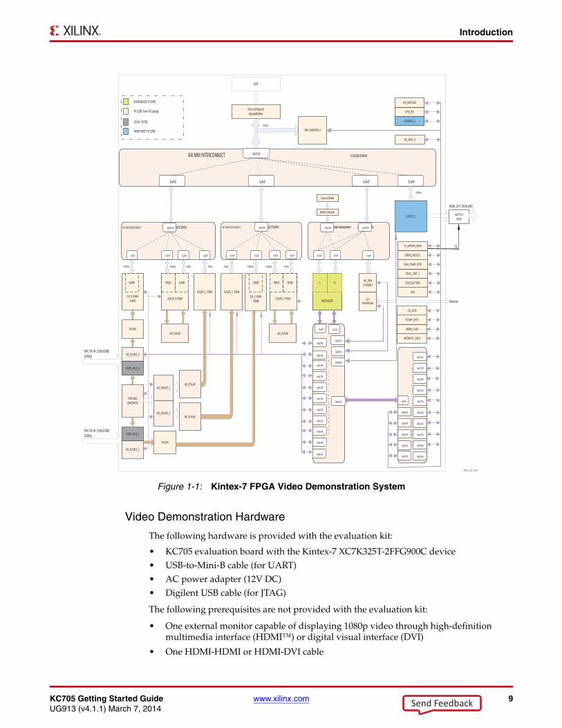
The provided video demonstration uses a pre-built Kintex-7 FPGA design (Figure 1-1) with these features:
• MicroBlaze processor
• External DDR3 SDRAM interface
• External flash memory interface
• On-chip memory (block RAM)
• Integrated Tri-Mode Ethernet MAC
• UART (connected from the KC705 board via the USB-UART connector)
• Interrupt controller (Intc) and timer
• GPIO (LCD, LEDs, buttons, switches, and rotary)
• Software-configurable XADC block
Send Feedback
KC705 Getting Started Guide www.xilinx.com 9UG913 (v4.1.1) March 7, 2014
Introduction
Video Demonstration Hardware
The following hardware is provided with the evaluation kit:
• KC705 evaluation board with the Kintex-7 XC7K325T-2FFG900C device• USB-to-Mini-B cable (for UART)• AC power adapter (12V DC)• Digilent USB cable (for JTAG)
The following prerequisites are not provided with the evaluation kit:
• One external monitor capable of displaying 1080p video through high-definition multimedia interface (HDMI™) or digital visual interface (DVI)
• One HDMI-HDMI or HDMI-DVI cable
X-Ref Target - Figure 1-1
Figure 1-1: Kintex-7 FPGA Video Demonstration System
Send Feedback
10 www.xilinx.com KC705 Getting Started GuideUG913 (v4.1.1) March 7, 2014
Chapter 1: Getting Started with the Kintex-7 FPGA KC705 Embedded Kit
• A host PC with TeraTerm Pro terminal program
• Adobe SVG plug-in for Internet Explorer
Video Demonstration Hardware Setup Instructions
This demonstration requires default switch and jumper settings on the KC705 board. For more information on the default switch settings, see the Hardware Test Board Setup Requirements section of UG883, Kintex-7 FPGA KC705 Evaluation Kit Getting Started Guide (Vivado Design Suite). Ensure the following jumper settings for the video demonstration:
• Jumper 27: Short pins 2 and 3
• Jumper 28: Short pins 2 and 3
• Jumper 29: Short pins 1 and 2
• Jumper 30: Short pins 1 and 2
• Jumper 32: Short pins 5 and 6
• Jumper 47: Short pins 1 and 2
• Jumper 48: Short pins 2 and 3
• Jumper 69: Short pins 1 and 2
• Jumper 3: Short pins 1 and 2
• Jumper 4: Short pins 1 and 2
• Jumper 43: Short pins 1 and 2
• Jumper 65: Short pins 1 and 2
• Jumper 68: Short pins 1 and 2
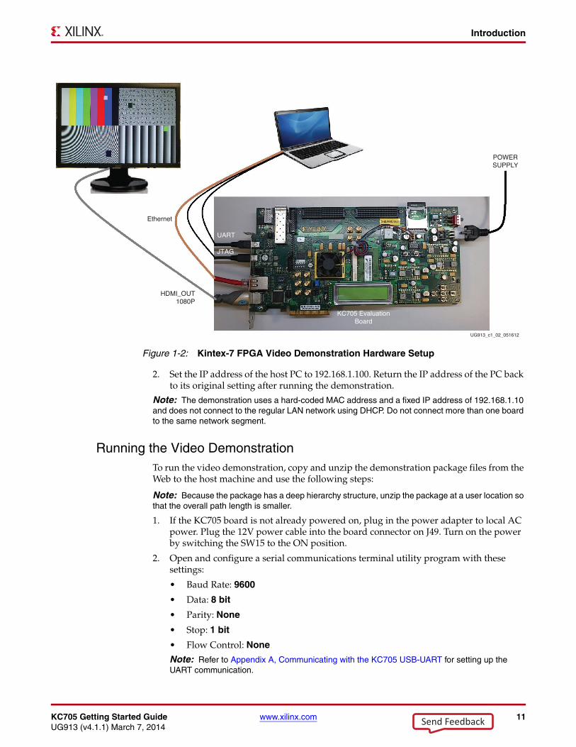
1. Connect the KC705 board, HDMI cables, display monitor, Ethernet cable, and USB cables as shown in Figure 1-2.
Send Feedback
KC705 Getting Started Guide www.xilinx.com 11UG913 (v4.1.1) March 7, 2014
Introduction
2. Set the IP address of the host PC to 192.168.1.100. Return the IP address of the PC back to its original setting after running the demonstration.
Note: The demonstration uses a hard-coded MAC address and a fixed IP address of 192.168.1.10 and does not connect to the regular LAN network using DHCP. Do not connect more than one board to the same network segment.
Running the Video DemonstrationTo run the video demonstration, copy and unzip the demonstration package files from the Web to the host machine and use the following steps:
Note: Because the package has a deep hierarchy structure, unzip the package at a user location so that the overall path length is smaller.
1. If the KC705 board is not already powered on, plug in the power adapter to local AC power. Plug the 12V power cable into the board connector on J49. Turn on the power by switching the SW15 to the ON position.
2. Open and configure a serial communications terminal utility program with these settings:
• Baud Rate: 9600
• Data: 8 bit
• Parity: None
• Stop: 1 bit
• Flow Control: None
Note: Refer to Appendix A, Communicating with the KC705 USB-UART for setting up the UART communication.
X-Ref Target - Figure 1-2
Figure 1-2: Kintex-7 FPGA Video Demonstration Hardware Setup
POWERSUPPLY
HDMI_OUT1080P
UG913_c1_02_051612
Ethernet
UART
KC705 EvaluationBoard
JTAG
Send Feedback
12 www.xilinx.com KC705 Getting Started GuideUG913 (v4.1.1) March 7, 2014
Chapter 1: Getting Started with the Kintex-7 FPGA KC705 Embedded Kit
3. Open a command shell with the Xilinx Design tools environment settings. Refer to Appendix B, Installation and Licensing of Xilinx Design Tools for Xilinx tool chain installation and licensing help.
Note: To set environment variables, run the settings32.bat file located in the Xilinx installation area. At the command prompt, type C:\Xilinx\Vivado\2013.x\settings32.bat (for Windows XP) or C:\Xilinx\Vivado\2013.x\settings64.bat (for Windows 7) and press Enter.
4. Go to the unzipped directory of the demonstration package and execute these commands to download the design and connect to the MicroBlaze processor:
$ cd k7-embedded-trd-rdf0283/ready_to_test/
$ xmd
XMD% fpga -f video_demo.bit
This command downloads the hardware bitstream into the FPGA but does not download the software application:
XMD% connect mb mdm
This command connects to the MicroBlaze processor debug module:
XMD% dow Video_Demo.elf
XMD% con
Send Feedback
KC705 Getting Started Guide www.xilinx.com 13UG913 (v4.1.1) March 7, 2014
Introduction
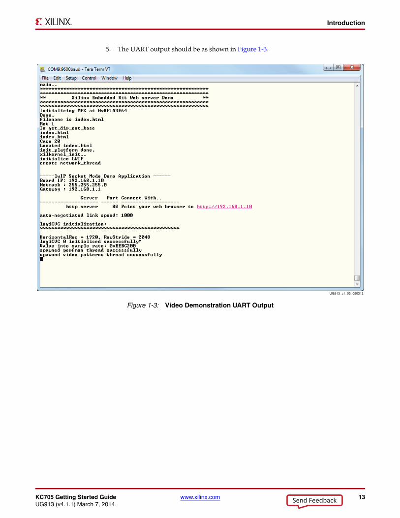
5. The UART output should be as shown in Figure 1-3.X-Ref Target - Figure 1-3
Figure 1-3: Video Demonstration UART Output
UG913_c1_03_050312
Send Feedback
14 www.xilinx.com KC705 Getting Started GuideUG913 (v4.1.1) March 7, 2014
Chapter 1: Getting Started with the Kintex-7 FPGA KC705 Embedded Kit
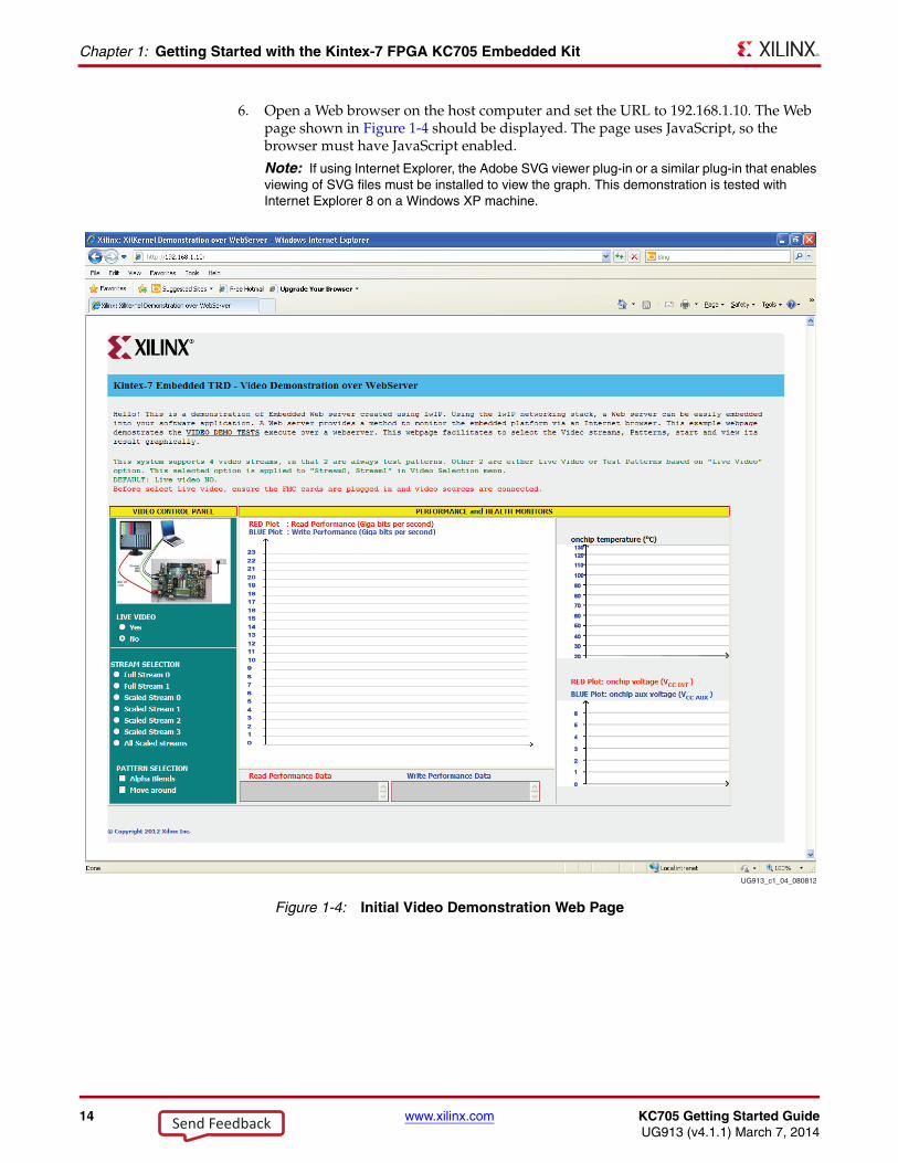
6. Open a Web browser on the host computer and set the URL to 192.168.1.10. The Web page shown in Figure 1-4 should be displayed. The page uses JavaScript, so the browser must have JavaScript enabled.
Note: If using Internet Explorer, the Adobe SVG viewer plug-in or a similar plug-in that enables viewing of SVG files must be installed to view the graph. This demonstration is tested with Internet Explorer 8 on a Windows XP machine.
X-Ref Target - Figure 1-4
Figure 1-4: Initial Video Demonstration Web Page
UG913_c1_04_080812
Send Feedback
KC705 Getting Started Guide www.xilinx.com 15UG913 (v4.1.1) March 7, 2014
Introduction
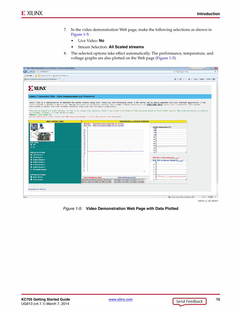
7. In the video demonstration Web page, make the following selections as shown in Figure 1-5:
• Live Video: No
• Stream Selection: All Scaled streams
8. The selected options take effect automatically. The performance, temperature, and voltage graphs are also plotted on the Web page (Figure 1-5).
X-Ref Target - Figure 1-5
Figure 1-5: Video Demonstration Web Page with Data Plotted
UG913_c1_05_032313
Send Feedback
16 www.xilinx.com KC705 Getting Started GuideUG913 (v4.1.1) March 7, 2014
Chapter 1: Getting Started with the Kintex-7 FPGA KC705 Embedded Kit
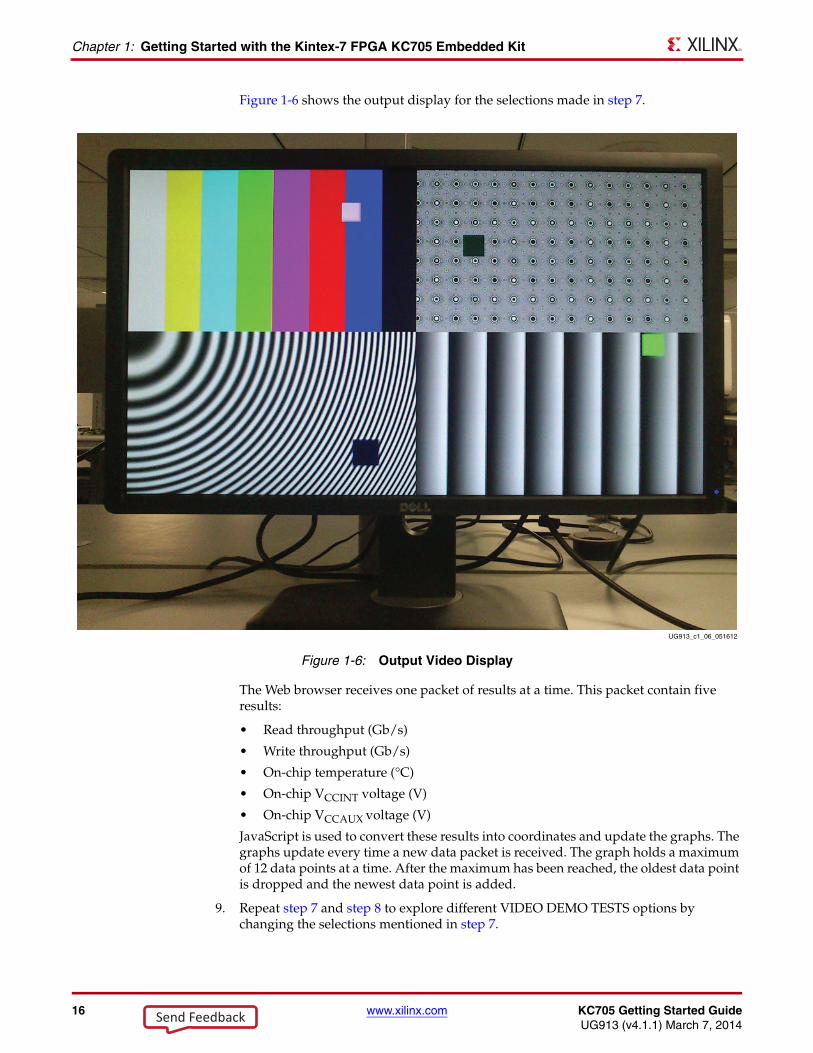
Figure 1-6 shows the output display for the selections made in step 7.
The Web browser receives one packet of results at a time. This packet contain five results:
• Read throughput (Gb/s)
• Write throughput (Gb/s)
• On-chip temperature (°C)
• On-chip VCCINT voltage (V)
• On-chip VCCAUX voltage (V)
JavaScript is used to convert these results into coordinates and update the graphs. The graphs update every time a new data packet is received. The graph holds a maximum of 12 data points at a time. After the maximum has been reached, the oldest data point is dropped and the newest data point is added.
9. Repeat step 7 and step 8 to explore different VIDEO DEMO TESTS options by changing the selections mentioned in step 7.
X-Ref Target - Figure 1-6
Figure 1-6: Output Video Display
UG913_c1_06_051612
Send Feedback
KC705 Getting Started Guide www.xilinx.com 17UG913 (v4.1.1) March 7, 2014
Introduction
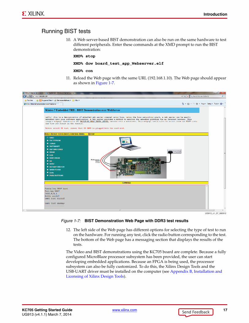
Running BIST tests10. A Web server-based BIST demonstration can also be run on the same hardware to test
different peripherals. Enter these commands at the XMD prompt to run the BIST demonstration:
XMD% stop
XMD% dow board_test_app_Webserver.elf
XMD% con
11. Reload the Web page with the same URL (192.168.1.10). The Web page should appear as shown in Figure 1-7.
12. The left side of the Web page has different options for selecting the type of test to run on the hardware. For running any test, click the radio button corresponding to the test. The bottom of the Web page has a messaging section that displays the results of the tests.
The Video and BIST demonstrations using the KC705 board are complete. Because a fully configured MicroBlaze processor subsystem has been provided, the user can start developing embedded applications. Because an FPGA is being used, the processor subsystem can also be fully customized. To do this, the Xilinx Design Tools and the USB-UART driver must be installed on the computer (see Appendix B, Installation and Licensing of Xilinx Design Tools).
X-Ref Target - Figure 1-7
Figure 1-7: BIST Demonstration Web Page with DDR3 test results
UG913_c1_07_080912
Send Feedback
18 www.xilinx.com KC705 Getting Started GuideUG913 (v4.1.1) March 7, 2014
Chapter 1: Getting Started with the Kintex-7 FPGA KC705 Embedded Kit
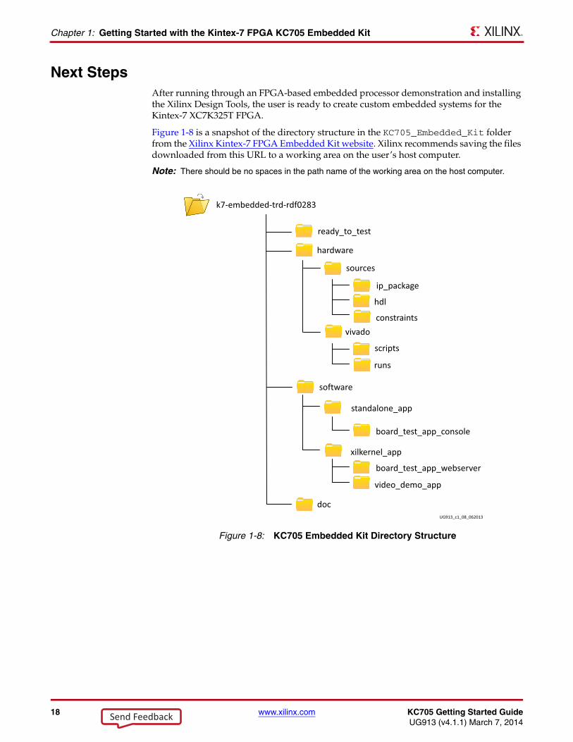
Next StepsAfter running through an FPGA-based embedded processor demonstration and installing the Xilinx Design Tools, the user is ready to create custom embedded systems for the Kintex-7 XC7K325T FPGA.
Figure 1-8 is a snapshot of the directory structure in the KC705_Embedded_Kit folder from the Xilinx Kintex-7 FPGA Embedded Kit website. Xilinx recommends saving the files downloaded from this URL to a working area on the user’s host computer.
Note: There should be no spaces in the path name of the working area on the host computer.
X-Ref Target - Figure 1-8
Figure 1-8: KC705 Embedded Kit Directory Structure
Send Feedback
KC705 Getting Started Guide www.xilinx.com 19UG913 (v4.1.1) March 7, 2014
Next Steps
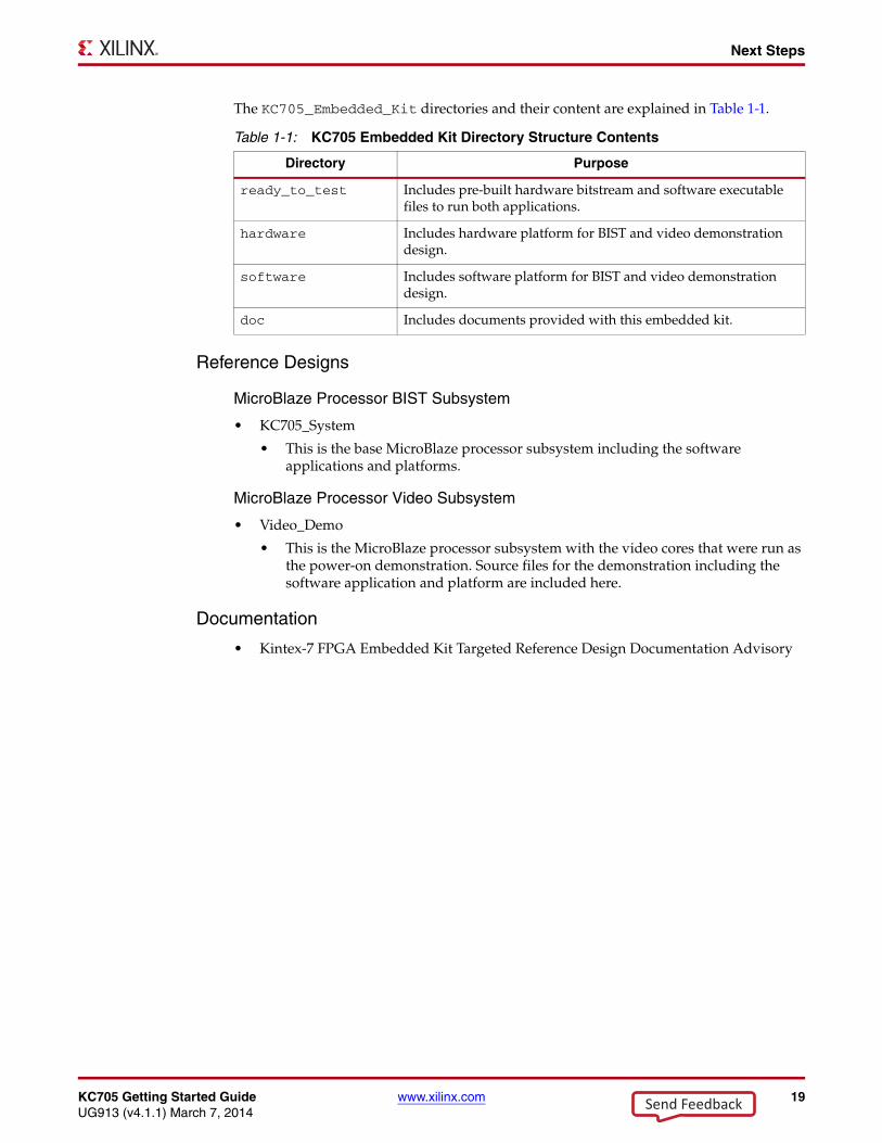
The KC705_Embedded_Kit directories and their content are explained in Table 1-1.
Reference Designs
MicroBlaze Processor BIST Subsystem
• KC705_System
• This is the base MicroBlaze processor subsystem including the software applications and platforms.
MicroBlaze Processor Video Subsystem
• Video_Demo
• This is the MicroBlaze processor subsystem with the video cores that were run as the power-on demonstration. Source files for the demonstration including the software application and platform are included here.
Documentation
• Kintex-7 FPGA Embedded Kit Targeted Reference Design Documentation Advisory
Table 1-1: KC705 Embedded Kit Directory Structure Contents
Directory Purpose
ready_to_test Includes pre-built hardware bitstream and software executable files to run both applications.
hardware Includes hardware platform for BIST and video demonstration design.
software Includes software platform for BIST and video demonstration design.
doc Includes documents provided with this embedded kit.
Send Feedback

20 www.xilinx.com KC705 Getting Started GuideUG913 (v4.1.1) March 7, 2014
Chapter 1: Getting Started with the Kintex-7 FPGA KC705 Embedded Kit
Send Feedback
KC705 Getting Started Guide www.xilinx.com 21UG913 (v4.1.1) March 7, 2014
Appendix A
Communicating with the KC705 USB-UART
This appendix explains the procedure for setting up UART communication between the KC705 board and the host machine.
Installing the USB-UART Driver1. Execute the installer for the Silicon Labs USB-UART virtual COM port (VCP) driver
from the Drivers_and_Tools folder in the package downloaded from the embedded kit home page: Drivers_and_Tools\CP210x_VCP_Win2K_XP_S2K3.exe.
2. Follow the installer instructions. Restart the computer when instructed to do so.
Connecting to the KC705 UART
3. Connect a USB Type-A to Mini-B 5-pin cable between the KC705 USB-UART connector (J21) and the host computer.
4. Power on the KC705 evaluation board if it is not already powered on.
Configuring the Host Computer
5. Right-click on My Computer and select Properties. Select the Hardware tab. Click on Device Manager.
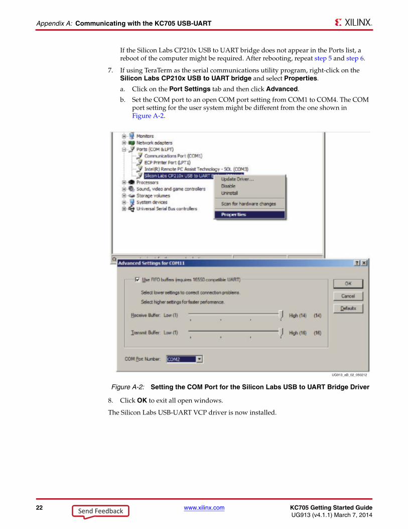
6. Expand the Ports (COM & LPT) entry as shown in Figure A-1. This shows the COM port assigned to the Silicon Labs CP210x USB to UART Bridge. This is the COM port to use in the serial communications program.
Note: The COM port setting for the user system might be different from the one shown in Figure A-1.
X-Ref Target - Figure A-1
Figure A-1: Silicon Labs USB to UART Bridge Properties
UG913_aB_08_050212
Send Feedback
22 www.xilinx.com KC705 Getting Started GuideUG913 (v4.1.1) March 7, 2014
Appendix A: Communicating with the KC705 USB-UART
If the Silicon Labs CP210x USB to UART bridge does not appear in the Ports list, a reboot of the computer might be required. After rebooting, repeat step 5 and step 6.
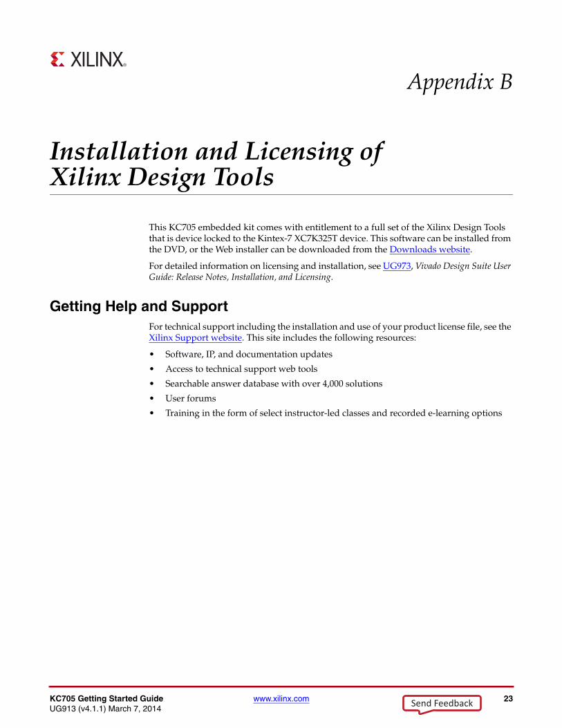
7. If using TeraTerm as the serial communications utility program, right-click on the Silicon Labs CP210x USB to UART bridge and select Properties.
a. Click on the Port Settings tab and then click Advanced.
b. Set the COM port to an open COM port setting from COM1 to COM4. The COM port setting for the user system might be different from the one shown in Figure A-2.
8. Click OK to exit all open windows.
The Silicon Labs USB-UART VCP driver is now installed.
X-Ref Target - Figure A-2
Figure A-2: Setting the COM Port for the Silicon Labs USB to UART Bridge Driver
UG913_aB_02_050212
Send Feedback
KC705 Getting Started Guide www.xilinx.com 23UG913 (v4.1.1) March 7, 2014
Appendix B
Installation and Licensing of Xilinx Design Tools
This KC705 embedded kit comes with entitlement to a full set of the Xilinx Design Tools that is device locked to the Kintex-7 XC7K325T device. This software can be installed from the DVD, or the Web installer can be downloaded from the Downloads website.
For detailed information on licensing and installation, see UG973, Vivado Design Suite User Guide: Release Notes, Installation, and Licensing.
Getting Help and SupportFor technical support including the installation and use of your product license file, see the Xilinx Support website. This site includes the following resources:
• Software, IP, and documentation updates
• Access to technical support web tools
• Searchable answer database with over 4,000 solutions
• User forums
• Training in the form of select instructor-led classes and recorded e-learning options
Send Feedback

24 www.xilinx.com KC705 Getting Started GuideUG913 (v4.1.1) March 7, 2014
Appendix B: Installation and Licensing of Xilinx Design Tools
Send Feedback
KC705 Getting Started Guide www.xilinx.com 25UG913 (v4.1.1) March 7, 2014
Appendix C
Additional Resources
Xilinx ResourcesFor support resources such as Answers, Documentation, Downloads, and Forums, see the Xilinx Support website.
For continual updates, add the Answer Record to your myAlerts.
For a glossary of technical terms used in Xilinx documentation, see the Xilinx Glossary.
Solution CentersSee the Xilinx Solution Centers for support on devices, software tools, and intellectual property at all stages of the design cycle. Topics include design assistance, advisories, and troubleshooting tips.
Further ResourcesThe most up to date information related to the KC705 board and its documentation is available on these websites.
Kintex-7 FPGA Embedded Kit
Kintex-7 FPGA Embedded Kit Answer Record (AR 52970)
Vivado Design Suite
UG883, Kintex-7 FPGA KC705 Evaluation Kit Getting Started Guide (Vivado Design Suite)
UG985, Kintex-7 FPGA Embedded Targeted Reference Design User Guide
UG973, Vivado Design Suite User Guide: Release Notes, Installation, and Licensing
Send Feedback

26 www.xilinx.com KC705 Getting Started GuideUG913 (v4.1.1) March 7, 2014
Appendix C: Additional Resources
Send Feedback

KC705 Getting Started Guide www.xilinx.com 27UG913 (v4.1.1) March 7, 2014
Appendix D
Warranty
THIS LIMITED WARRANTY applies solely to standard hardware development boards and standard hardware programming cables manufactured by or on behalf of Xilinx (“Development Systems”). Subject to the limitations herein, Xilinx warrants that Development Systems, when delivered by Xilinx or its authorized distributor, for ninety (90) days following the delivery date, will be free from defects in material and workmanship and will substantially conform to Xilinx publicly available specifications for such products in effect at the time of delivery. This limited warranty excludes: (i) engineering samples or beta versions of Development Systems (which are provided “AS-IS” without warranty); (ii) design defects or errors known as “errata”; (iii) Development Systems procured through unauthorized third parties; and (iv) Development Systems that have been subject to misuse, mishandling, accident, alteration, neglect, unauthorized repair or installation. Furthermore, this limited warranty shall not apply to the use of covered products in an application or environment that is not within Xilinx specifications or in the event of any act, error, neglect or default of Customer. For any breach by Xilinx of this limited warranty, the exclusive remedy of Customer and the sole liability of Xilinx shall be, at the option of Xilinx, to replace or repair the affected products, or to refund to Customer the price of the affected products. The availability of replacement products is subject to product discontinuation policies at Xilinx. Customer may not return product without first obtaining a customer return material authorization (RMA) number from Xilinx.
THE WARRANTIES SET FORTH HEREIN ARE EXCLUSIVE. XILINX DISCLAIMS ALL OTHER WARRANTIES, WHETHER EXPRESS, IMPLIED OR STATUTORY, INCLUDING, WITHOUT LIMITATION, ANY WARRANTY OF MERCHANTABILITY, FITNESS FOR A PARTICULAR PURPOSE, OR NON-INFRINGEMENT, AND ANY WARRANTY THAT MAY ARISE FROM COURSE OF DEALING, COURSE OF PERFORMANCE, OR USAGE OF TRADE. (2008.10)
Do not throw Xilinx products marked with the “crossed out wheelie bin” in the trash. Directive 2002/96/EC on waste electrical and electronic equipment (WEEE) requires the separate collection of WEEE. Your cooperation is essential in ensuring the proper management of WEEE and the protection of the environment and human health from potential effects arising from the presence of hazardous substances in WEEE. Return the marked products to Xilinx for proper disposal. Further information and instructions for free-of-charge return available at: www.xilinx.com/ehs/weee.
Send Feedback

28 www.xilinx.com KC705 Getting Started GuideUG913 (v4.1.1) March 7, 2014
Appendix D: Warranty
Send Feedback


![Kintex-7 FPGA KC705 Evaluation Kit-KC705 Evaluation Board for the Kintex-7 FPGA User Guide (UG810) [Ref 1]-Kintex-7 FPGA KC705 Base Targeted Reference Design User Guide (UG882) [Ref](https://img.pdfslide.us/doc/110x75/5f6f6c0b693ef83e28062053/kintex-7-fpga-kc705-evaluation-kc705-evaluation-board-for-the-kintex-7-fpga-user.jpg)