Embed Size (px)
Citation preview

Table of Contents 1. Introduction ................................................................................................... 2 2. Quality Control .............................................................................................. 2
2.1 Installation QA Records........................................................................ 2 2.2 Installer Experience .............................................................................. 2 2.3 Installer Responsibilities ....................................................................... 2 2.4 Final Inspection and Integrity Testing ................................................... 2
3. Earthwork ..................................................................................................... 3 3.1 General ................................................................................................ 3 3.2 Barrier Membrane Protection ............................................................... 3 3.3 Preparation of the Subgrade ................................................................ 3 3.4 Panel Layout Plan ................................................................................ 3
4. Barrier Membrane installation ....................................................................... 4 4.1 Pre-fabricated Panels ........................................................................... 4 4.2 Weather Limitations ............................................................................. 4 4.3 Rolls ..................................................................................................... 4 4.4 Transport and Storage ......................................................................... 4 4.5 Deployment and Preparation ................................................................ 4 4.6 Seam Welding ...................................................................................... 4 4.7 Test Welds ........................................................................................... 5 4.8 Weld Quality ......................................................................................... 6 4.9 Cover Material and Backfilling of Anchor Trench ................................. 6 4.10 Barrier Membrane Acceptance ............................................................. 6
5. Sampling and Testing ................................................................................... 6 5.1 Non-Destructive Testing ....................................................................... 6 5.2 Qualitative Destructive Testing ............................................................. 7
6. Details ........................................................................................................... 7 6.1 Corners ................................................................................................ 7 6.2 Connections to concrete structures ...................................................... 8 6.3 Drains and flanges ............................................................................... 8 6.4 Ancillaries ............................................................................................. 9 6.5 Flashing of penetrations ....................................................................... 9 6.6 Anchor trenches ..................................................................................10 6.7 Foundations ........................................................................................10
7. Appendix ......................................................................................................17 7.1 Defects and Repair Procedure ............................................................17 7.2 Welding equipment .............................................................................17 7.3 Laboratory testing of welded seams ....................................................18 7.4 Weather Protection .............................................................................18 7.5 Sample Field Seam Weld Record .......................................................19 7.6 Useful References ...............................................................................20
CONSTRUCTION PRODUCTS KINGFIELDKingfield Puraflex Membrane Details & Installation
Page 1 of 20PURAFLEX DETAILS & INSTALLATION – v1.12.01.14 “Puraflex” is a trademark of Industrial Textiles & Plastics Ltd www.puraflex.com
1. INTRODUCTION Industrial Textiles & Plastics Ltd. is an established producer of barrier membrane materials used for the manufacture of gas tight suits and chemical protection clothing fabrics. This barrier technology and manufacturing experience has been used to develop Puraflex® which has been engineered specifically for the remediation of contaminated land, water resources and groundwater protection, environmental protect ion and secondary containment installations. Puraflex® has enhanced resistance to a wide range of pollutants including hydrocarbons, industrial chemicals, and toxic waste, natural and radioactive gases. The material has been subjected to a detailed test programme and our data is the result of chemical resistance testing to both industry and proprietary test methods. Puraflex® is a composite membrane comprising thermal weldable polymer layers on both sides of a chemical -resistant inner core. Whilst the upper and lower polymer layers are UV stabilised, it is recommended that the membrane is only used for covered installations. Installed using conventional hot air wedge-welding equipment, it is classed as a GBR-P polymeric geosynthetic barrier for covered installations. It can remain exposed prior to covering for up to 21 days. This installation guide summarises best practice and procedures for different aspects of Puraflex® environmental protection barrier membrane installation and welding. All procedures, operations and methods shall be in accordance with the Engineer’s speci�cations, plans, and drawings.
2. QUALITY CONTROL 2.1 Installation QA Records
As detailed in the manufacturer’s installation instructions, t he Installer shall record details of the following activities:
2.1.1 Materials inspection and tests The Installer shall check material delivered to site for damage, checking and recording the roll serial numbers.
2.1.2 Panel Layout Plan The Installer shall prepare a Panel Layout Plan to record the batch serial number and coverage of each roll.
2.1.3 Installation and weld testing The Installer shall monitor, inspect and record all welding, including weld parameters and testing of regular test welds. Completed welded seams shall be tested by destructive and non-destructive methods.
2.1.4 Faults and repairs The Installer shall record all faults and repairs to the membrane.
2.2 Installer Experience The Installer shall have experience of installing geomembranes of the type specified for the Works. The Installer shall be suitably quali�ed to install the manufacturer’s barrier membrane. An acceptable example is the British Geomembrane Association (BGA)/Thermal Welding Institute (TWI/CSWIP) third party accreditation scheme. In accordance with the Environment Agency requirements, at least two crew members must be accredited to BS EN 13067 and all other crew members (except for a maximum of one trainee) must be accredited to the CSWIP Entry Level. The installation shall be under the constant direction of a field installation supervisor or master welder who shall remain on site and be responsible, throughout the membrane installation, for membrane layout, welding, testing, repairs, and all other activities.
2.3 Installer Responsibilities The Installer shall be responsible for the membrane at all times during the Contract and shall adopt whatever measures are necessary to ensure its stability and protect it from damage. These measures shall include the use of sufficient temporary surcharge in the form of durable sandbags, tyres or similar weights without sharp edges, to be placed on the membrane immediately after laying and before welding to prevent slipping and damage by wind or other agents prior to covering. The Installer's attention is drawn to the need to provide adequate restraint at free edges of sheet material before anchoring or welding to the adjacent seam in order to prevent uplift by wind.
2.4 Final Inspection and Integrity Testing It is recommended that verification of the barrier membrane installation shall be performed by independent Inspectors.
Kingfield Puraflex Membrane Details & Installation
Page 2 of 20PURAFLEX DETAILS & INSTALLATION – v1.12.01.14 “Puraflex” is a trademark of Industrial Textiles & Plastics Ltd www.puraflex.com

Final Inspection and Integrity Testing shall be performed prior to covering the barrier membrane; covering the barrier must not begin until the installation has passed Inspection. All non-conformances shall be resolved by the Installer to the Inspector’s satisfaction before the Installation can be certified as passed. The Final inspection should include: � Visual inspections of the entire barrier membrane surface, seam welds and penetration seals; � Non-Destructive testing of seam welds (see Section 5.1); � Dielectric Testing. A reliable method of detecting holes in barrier membranes is the Dielectric test method
using electrical conductivity. Other test methods may include Smoke or Trace Gas testing (where smoke or trace gas is injected below the barrier); There are advantages and disadvantages to the different methods. The main issue with smoke or trace gas testing is achieving sufficient pressure below the membrane to ensure that the smoke or tracer gas is present below all parts of the membrane. If done correctly it works well, if not it is not really effective. It is also difficult to inject the gas and build up a pressure below large slabs that are poured in sections since there will be a large unsealed open area around the edges.
� Photographs of all penetration seals and damaged areas with subsequent repairs. The information should be included in the inspection report.
3. EARTHWORK 3.1 General
All surfaces to be covered shall be smooth and free of all foreign and organic material, sharp objects, or debris of any kind. The subgrade shall provide a firm, unyielding foundation with no sharp changes or abrupt breaks in grade.
3.2 Barrier Membrane Protection To minimise the risk of puncturing, the barrier membrane should be adequately protected on either side with a suitable needle-punched non-woven geotextile or sand.
3.3 Preparation of the Subgrade 3.3.1 So that damage to the membrane is avoided, the essential requirement for the installation of the barrier
membrane is a smooth, dry and clean working surface. 3.3.2 No standing water or excess moisture shall be present. 3.3.3 The water table level should be determined and if it is higher than the base of the excavation, adequate drainage
should be installed to prevent water pressure build up below the barrier membrane. 3.3.4 Particular attention should be paid to the following:
i Grain size and angularity: The subgrade should be free of all rocks, sticks, stones, roots, sharp objects or any debris of any kind, which may puncture the membrane. Any stone, which protrudes above the level of the surface of the subgrade, should be stone picked and any indentation remaining should be filled and compacted with suitable material;
ii Smooth and firm: The surface should provide a firm unyielding foundation for the membrane with no sudden, sharp or abrupt change or break in gradient.
3.3.5 When carrying out any welding procedure on a Bentonite Enhanced Soil (BES) subgrade, it is important that particular attention is given to the cleaning process in preparation for welding. When Bentonite attaches itself to the membrane, particularly in wet conditions, it is very difficult to clean the membrane and the number of weld failures increases without due care and attention.
3.3.6 Geosynthetic Clay Liners (GCL) also present welding problems when placed directly underneath the membrane since the Bentonite powder, which is placed in the overlaps of GCL panels, is often scattered by the wind or water and causes cleaning problems in preparation for welding. When placing the Bentonite powder, excess amounts of powder should not be placed in the joints and none on the membrane.
3.3.7 If after inspection of the material that is to be placed on top of the barrier membrane, it is deemed to be unsuitable, a needle-punched non-woven geotextile may be recommended as a protective layer. Installation of a protective layer should be carried out after acceptance of the tested barrier membrane. The protective cover shall be spread in a manner to ensure that the barrier membrane follows the contours of the ground and no bridging or stretching of the material occurs.
3.4 Panel Layout Plan 3.4.1 The Installer shall provide a detailed Panel Layout Plan showing the proposed layout and sequence of the
membrane placement. 3.4.2 The Installer shall arrange the panels so that the seams are aligned parallel to the line of maximum slope (i.e.
normal to contours), whenever practicable in accordance with accepted good practice.
Kingfield Puraflex Membrane Details & Installation
Page 3 of 20PURAFLEX DETAILS & INSTALLATION – v1.12.01.14 “Puraflex” is a trademark of Industrial Textiles & Plastics Ltd www.puraflex.com

3.4.3 The free edges of each panel shall be adequately weighed down with sand bags, tyres or by other means in readiness for seam welding.
3.4.4 Roll batch serial numbers should be recorded on the Panel Layout Plan to record the coverage and location of each roll.
4. BARRIER MEMBRANE INSTALLATION On-site progress of the work, as well as the climatic and working conditions shall be recorded and on completion, a layout plan prepared to record the location and sizes of each panel of barrier membrane.
4.1 Pre-fabricated Panels Pre-fabricated panels have the advantage of being installed relatively quickly and cleanly. They should be considered where site conditions make in-situ welding difficult or inappropriate. Panels minimise weather-induced delays and reduce on-site welding and can be made to the necessary detail, shape and size and delivered to site folded and rolled ready for deployment.
4.2 Weather Limitations Barrier membrane deployment or welding shall only proceed between ambient temperatures of 4ºC and 30ºC. Placement can proceed below 4ºC only after it has been verified by the inspector that the material can be welded according to the specification. No deployment of membranes or welding will take place during any precipitation or in the presence of excess moisture (fog, dew, rain), blowing dust or winds over 10 km/hr. No placement or welding of membranes should take place in areas of standing water.
4.3 Rolls The barrier membrane is supplied in rolls. The surface of the barrier membrane shall not have pinholes or bubbles. Labels on each roll shall identify the manufacturer, product name and type, the weight per square metre, the length, width and weight of the roll and the batch number. The roll serial number must be recorded on the Layout Plan.
4.4 Transport and Storage Care should be taken when moving, transporting or handling rolls to avoid physical damage, puncturing or any tainting which may interfere with seam welding. The barrier membrane shall be stored under cover so as to be protected from puncture, dirt, grease, moisture, sunlight and excessive heat. Damaged material shall be quarantined and stored separately for repair or replacement. The rolls shall be stored on a prepared smooth dry surface (or fully boarded wooden pallets; note that slatted pallets with sharp corners will damage the rolls) and stacked no more than two pallets high. The bottom rolls on the pallet need to be chocked to prevent them rolling. Storage between 5 to 30 ºC at 40 to 65% humidity under non-condensing conditions is recommended.
4.5 Deployment and Preparation 4.5.1 Deployment
The rolls shall be deployed with care. i Equipment or tools shall not damage the barrier membrane during handling, transportation and
deployment; ii Personnel working on the barrier membrane shall not smoke or wear damaging shoes; iii The method used to unroll the panels shall not cause scratches or crimps in the barrier membrane and
shall not damage the supporting soil; iv Adequate loading (e.g. sand bags or similar items that will not damage the barrier membrane) shall be
placed to prevent uplift by wind (in case of high winds, continuous loading is recommended along edges of panels to minimize risk of wind flow under the panels).
4.5.2 Preparation After unrolling the membrane, its position is adjusted so that a suitable overlap is achieved for the welding process. Before welding, the membrane shall be checked for any damage and to ensure that it is clean, dry and free of any dust or dirt particles. This is particularly important if the membrane is wet at the beginning of the day when it is likely that dew is present. Where the edge of a panel of membrane has been laying on wet sub-grade, it may be necessary to remove any mud stuck to the underside. Any surface water in the area of the seam must be removed.
4.6 Seam Welding 4.6.1 The approved seam welding process is hot air wedge welding. A Leister Twinny-S hot air wedge welder is
recommended for optimum results using a 25mm knurled roller for a single seam overlap-weld.
Kingfield Puraflex Membrane Details & Installation
Page 4 of 20PURAFLEX DETAILS & INSTALLATION – v1.12.01.14 “Puraflex” is a trademark of Industrial Textiles & Plastics Ltd www.puraflex.com

4.6.2 Puraflex® incorporates an inner chemical resistant core with a protective thermally weldable modified polyolefin coating on both sides which is compatible with conventional hot air wedge welding equipment.
4.6.3 Conventional overlap-welding is recommended for joining.
. Fig. 4b
Standard single seam overlap-weld with 25mm knurled roller. A Leister Twinny-S hot air wedge welder is recommended for optimum results.
4.6.4 Proposed Joining Techniques The Installer should submit method statements prior to commencing installation, detailing the following as a minimum: i Proposed welding technique, joining machinery, overlap widths and overlap preparation prior to welding,
acceptable temperature ranges for welding, acceptable maximum welding speed. ii Proposed non-destructive test technique or techniques.
4.6.5 On side slopes, welds shall be oriented in the general direction of maximum slope, i.e. oriented down, not across, the slope. In corners and odd-shaped geometric locations, the number of field welds shall be minimised. No base T-weld shall be closer than 2 metres from the toe of the slope. Welds shall be aligned with the least possible number of wrinkles and “�sh -mouths.” If a �sh -mouth or wrinkle is found, it shall be relieved and patched.
4.6.6 Barrier membrane panels must have a finished overlap of 100mm. 4.6.7 Cleaning solvents may not be used.
4.7 Test Welds 4.7.1 Field test welds shall be conducted on the barrier membrane to verify that welding conditions are satisfactory.
The Installer shall perform test welds with each welding machine and operator at least at the start of each shift, after every four hours of operation and also following any period of machine shutdown or change of operator. The test welds shall be made and the Installer shall cut five 25mm wide field tabs from the seam length. The tabs shall be subjected to field qualitative destructive testing using a tensometer. The five tabs shall be tested in peel mode. NOTE: Welded seams must be allowed to cool before performing any peel testing; testing warm seams will provide false peel test results. The seam will be deemed to have passed if the failure occurs solely in the parent material and does not encroach into the seam. The seam will be deemed to have failed if any of the failure encroaches the seam. The peel test indicates whether or not the sheets are homogeneously and satisfactorily joined through the material thickness. The test specimen is pulled perpendicular to the weld until complete separation occurs. Analysis of the fracture surfaces provides qualitative information about the joint integrity. Ductile failure in the parent material indicates a good quality weld. If the correct welding parameters have not been followed during the welding process, it will become clear when specimens are peel tested. This type of test is an aggressive test of a seam weld. For example, if the temperature of the hot air wedge was set too hot in relation to the speed of operation, then it is most likely that the area of the material beside the weld is brittle and will break at a lower than expected value. If a test weld fails field destructive testing then the welding machine and the Operator shall not be allowed to perform field welding until the deficiencies are corrected and both machine and Operator have achieved a conforming test weld.
4.7.2 Assessment of Test Weld Results Each specimen shall be 25mm wide with a grip separation of 100mm. The weld shall be centred between the clamps. The rate of grip separation shall be 50mm per minute. The seam will have deemed to pass if the failure occurs solely in the parent material and does not enter the seam. Elongation measurements are omitted for field-testing.
Kingfield Puraflex Membrane Details & Installation
Page 5 of 20PURAFLEX DETAILS & INSTALLATION – v1.12.01.14 “Puraflex” is a trademark of Industrial Textiles & Plastics Ltd www.puraflex.com

4.8 Weld Quality 4.8.1 Types of Imperfection
The most important step in identifying weld imperfections is to inspect the weld visually. In the case of hot air wedge welded seams, a visual inspection should take account of the following: i The nip/drive roller marks may show on the surface of the membrane when using knurled rollers. Their
depth should be examined to ensure that the rollers have not created a rut, i.e. the indentation should be barely capable of being felt;
ii The seam should be checked for uniformity of width and surface continuity. In the case of dual track seam both seams should be clearly identifiable and separated by an air channel;
iii There should be enough of a flap outside of the weld to allow for peel testing of the weld during a destructive test;
4.8.2 Origins of Imperfections The origin of weld imperfections could include the following: i Welding in unsuitable environmental conditions, i.e. during rain, excessive wind or on poor subgrade; ii Unsuitable welding equipment or machine settings, i.e. using the incorrect welding parameters; iii Poor operation of the equipment, lack of operator training or awareness. Either one or a combination of the above list could lead to poor quality welds being produced.
4.9 Taped joints 4.9.1 To maintain the installation’s integrity, s eam welding is the recommended method for jointing. 4.9.2 Taped joints compromise any membrane’s integrity by providing a pathway for the challenge chemical through
the adhesive. An adhesive claiming to be ‘Hydrocarbon Resistant’ may simply mean that a n adhesive may be resilient to certain hydrocarbons which have no obvious relationship to the adhesive’s ability to block a challenge hydrocarbon to a level that ensures adequate protection over time. Furthermore the vagueness of the word “hydrocarbon” can lead to false claims that an adhesive good for one hydrocarbon (e.g. methane) is automatically good for a very different type of hydrocarbon (e.g. benzene).
4.9.3 Where taped joins are a necessity, tape joints should only be used where joints are under continuous compressive loads e.g. under-slab installations. Tape joints are not suitable for wall installations or other installations where the joint is not under compression.
4.10 Cover Material and Backfilling of Anchor Trench The barrier membrane shall be covered within 21 days of exposure. The covering operation shall not damage the barrier membrane. The cover soil material shall be free of foreign and organic material, sharp objects, or debris of any kind, which could potentially damage the barrier membrane. No construction equipment or machinery shall operate directly on the barrier membrane. The use of lightweight machinery (e.g. generator) with low ground pressure may be allowed subject to the approval of the Engineer. Any damage shall be repaired prior to backfilling.
4.11 Barrier Membrane Acceptance The Installer shall be responsible for the barrier membrane until accepted by the client. Final acceptance is when all of the following conditions are met: i The Installation is finished. ii Installation QA Records are complete. iii The Installation has been certified as passed by the Final Inspection and Integrity Testing Inspector.
5. SAMPLING AND TESTING 5.1 Non-Destructive Testing
The Inspector shall perform non-destructive testing along the entire lengths of all seams including patches and repairs. In the event of a seam failing non-destructive testing the Inspector shall identify the failed area. The Inspector shall then subject the repair to further non-destructive testing until any repair passes the test. Recommended non-destructive testing techniques are visual inspection, air lance and vacuum box testing.
5.1.1 Active Weld Inspection The installer/operator inspects the seam area during the welding process, however only certain defects affecting weld quality can be detected. Therefore further Air Lance Testing and/or Vacuum Box Testing is required to check and validate the integrity of the welding.
5.1.2 Air Lance Testing
Kingfield Puraflex Membrane Details & Installation
Page 6 of 20PURAFLEX DETAILS & INSTALLATION – v1.12.01.14 “Puraflex” is a trademark of Industrial Textiles & Plastics Ltd www.puraflex.com

This technique involves forcing a high-pressure jet of air along the weld edge. Signs of lifting or bubbling provide an indication of an unsatisfactory seam weld.
5.1.3 Vacuum Box Testing This method is used in areas of complex welding detail, or where other methods are not feasible, and comprises treating the area of the barrier membrane to be tested with a soap solution and a vacuum box over the soaped area. Leaks are detected by the appearance of bubbles.
5.1.4 Air Pressure Testing of Double Seam Welds There is a risk of irrevocably stretching the material when over-pressurising the channel. Air Pressure Testing of double seam welds is therefore not recommended.
5.2 Qualitative Destructive Testing Destructive testing should be minimised to preserve the integrity of the barrier membrane. If specified, the following is recommended:
5.2.1 Sampling Procedure The Installer shall cut a 25mm wide field tab from the beginning and end of each completed seam and shall subject it to qualitative destructive testing in peel mode using an independently calibrated field tensometer. Using a field tensometer, the inspector shall test a minimum of five 25mm wide samples for peel strength. The Installer shall also record the date, location, and pass or fail description. NOTE: Welded seams must be allowed to cool before performing any peel testing; testing warm seams will provide false peel test result.
5.2.2 Field Testing The seam will be deemed to have passed qualitative destructive testing if the failure occurs solely in the parent material and does not encroach into the seam. The seam will be deemed to have failed if any of the failure encroaches the seam. The peel test indicates whether or not the sheets are homogeneously and satisfactorily joined through the material thickness. The test specimen is pulled perpendicular to the weld until complete separation occurs. Analysis of the fracture surfaces provides qualitative information about the joint integrity. Ductile failure in the parent material indicates a good quality weld. If the correct welding parameters have not been followed during the welding process, it will become clear when specimens are peel tested. This type of test is an aggressive test of a seam weld. For example, if the temperature of the hot air wedge was set too hot in relation to the speed of operation, then it is most likely that the area of the material beside the weld is brittle and will break at a lower than expected value.
5.2.3 Procedures for Destructive Test Failure Whenever a sample fails the field destructive test, the following procedures shall apply: The Installer can retrace the welding path to an intermediate location (usually 3 metres from the location of the failed test), and take a sample for an additional field test. If this test passes, then the weld shall be patched between that location and the original failed location. If the test fails, then the process is repeated. The Installer shall patch the weld between the failed location and any passed test locations. Over the length of weld failure, the Installer shall either cut out the old weld, reposition the panel and re-weld or weld a patch.
5.2.4 Archive Samples The installer should prepare a welded seam sample 0.5m wide by 1.5m long which will be cut into three sections; one section to be tested by the Installer, one section to be sent to an off-site laboratory if required, and the third section to be kept in archive storage by the client. Standard procedure is for the Installer to cut ten tabs from his portion of the sample and to test each alternative one in peel and shear.
6. DETAILS 6.1 Corners
In tight corners, trimming away excess membrane may be necessary. When trimming the membrane, sufficient overlap (minimum 100mm) should be left to provide material for hot air welding. The corner should be reinforced with a formed patch of the membrane and should extend at least 150mm outside the first corner welds in order to ensure that they are completely covered.
Kingfield Puraflex Membrane Details & Installation
Page 7 of 20PURAFLEX DETAILS & INSTALLATION – v1.12.01.14 “Puraflex” is a trademark of Industrial Textiles & Plastics Ltd www.puraflex.com

Outside corners should also be reinforced by hot air welding a strip of membrane material extending a minimum of 50mm either side of the corner.
6.2 Connections to concrete structures Connections to concrete structures are typically made by either embedding a Polyethylene channel into the concrete to which the membrane can be welded or by mechanically fixing using a drilled steel flatbar.
6.3 Drains and flanges A concrete base is required to anchor the discharge pipe and flange. The membrane should be mechanically fastened to the flange and sealed.
Kingfield Puraflex Membrane Details & Installation
Page 8 of 20PURAFLEX DETAILS & INSTALLATION – v1.12.01.14 “Puraflex” is a trademark of Industrial Textiles & Plastics Ltd www.puraflex.com

6.4 Ancillaries
Gasket Materials: Sealants: Metal battens: Fastenings: Embedded channels: Vents and Top hats:
min. 5mm closed-cell Neoprene Bitumen or Silicone, as compatible min. 6mm x 60mm stainless steel Stainless steel (bolts, nuts, washers etc.) High Density Polyethylene (HDPE) Vents and Top hats shall be made from Puraflex
6.5 Flashing of penetrations The pipe needs to be firmly anchored and the pipe temperature must not exceed 60 ºC. Where the pipe is to penetrate, cut a hole in the membrane ensuring a tight seal is made without stretching the membrane. Top hats should be installed around penetrations. The pipe and the membrane are flashed together by creating three cut-outs of the membrane material and hot-air welding as illustrated.
Kingfield Puraflex Membrane Details & Installation
Page 9 of 20PURAFLEX DETAILS & INSTALLATION – v1.12.01.14 “Puraflex” is a trademark of Industrial Textiles & Plastics Ltd www.puraflex.com

6.6 Anchor trenches Top anchoring the membrane is achieved by holding it in place in a trench, minimum 400 x 400 mm. All corners over which the membrane rests should be rounded. The membrane should be covered where intermediate or base anchoring is necessary, the membrane can be anchored using an anchor trench or ballast. Where the ballast is above the membrane, a protective geotextile should be used.
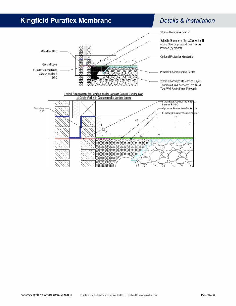
6.7 Foundations 6.7.1 When used as a barrier in building foundations, Puraflex® membrane should be continuous over the whole floor
plan area of the structure and stepped down across the cavity. Cavity walls, voids formed in hollow concrete block walls etc. should be sealed to avoid accumulation of vapours or gas.
6.7.2 Puraflex barrier membrane can be laid over raft formations and suspended concrete floors or under-ground bearing slabs and suspended timber floors.
6.7.3 When placed over concrete, the concrete should be dense, smooth and free from any projections which may damage the barrier membrane. The barrier membrane should then be covered with the insulation, screed or other suitable protective layer as soon as possible after installation.
6.7.4 When placed beneath ground bearing slabs, both sides of the barrier membrane should be adequately protected with a sand or concrete blinding layer to a minimum thickness of 50mm or a suitable needle-punch geotextile. The underside of the barrier membrane should not be laid directly onto a granular fill. When reinforced concrete is to be laid over the membrane, wire reinforcements or spacers must not contact the barrier membrane.
6.7.5 The barrier membrane should be sufficiently loosely laid against upstands to ensure that the barrier membrane is not stretched or displaced when applying the screed or concrete.
6.7.6 Service penetrations should enter the building above the sealed floor slab. Where this is not possible, penetrations should be kept to a minimum. Where services need to penetrate the membrane, Top Hat gas tight seals are required around each point of entry.
6.7.7 Where applicable, soap bars should be positioned on the inside cavity wall blocks so that timber frame constructions do not puncture the barrier membrane.
Kingfield Puraflex Membrane Details & Installation
Page 10 of 20PURAFLEX DETAILS & INSTALLATION – v1.12.01.14 “Puraflex” is a trademark of Industrial Textiles & Plastics Ltd www.puraflex.com

6.7.8 Typical Arrangements – Raft Formation (CAD Drawings available on request)
Kingfield Puraflex Membrane Details & Installation
Page 11 of 20PURAFLEX DETAILS & INSTALLATION – v1.12.01.14 “Puraflex” is a trademark of Industrial Textiles & Plastics Ltd www.puraflex.com

6.7.9 Typical Arrangements – Ground Bearing Slab (CAD Drawings available on request)
Kingfield Puraflex Membrane Details & Installation
Page 12 of 20PURAFLEX DETAILS & INSTALLATION – v1.12.01.14 “Puraflex” is a trademark of Industrial Textiles & Plastics Ltd www.puraflex.com
Kingfield Puraflex Membrane Details & Installation
Page 13 of 20PURAFLEX DETAILS & INSTALLATION – v1.12.01.14 “Puraflex” is a trademark of Industrial Textiles & Plastics Ltd www.puraflex.com
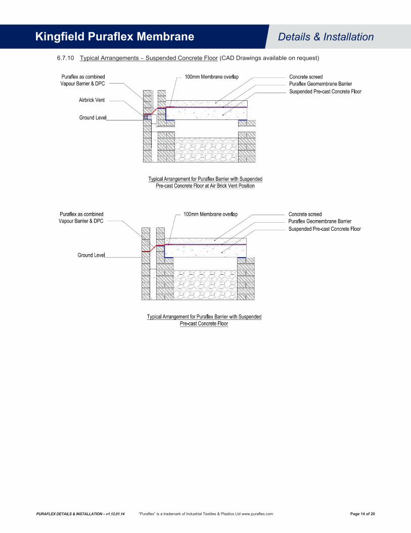
6.7.10 Typical Arrangements – Suspended Concrete Floor (CAD Drawings available on request)
Kingfield Puraflex Membrane Details & Installation
Page 14 of 20PURAFLEX DETAILS & INSTALLATION – v1.12.01.14 “Puraflex” is a trademark of Industrial Textiles & Plastics Ltd www.puraflex.com

6.7.11 Typical Arrangements – Suspended Timber Floor (CAD Drawings available on request)
Kingfield Puraflex Membrane Details & Installation
Page 15 of 20PURAFLEX DETAILS & INSTALLATION – v1.12.01.14 “Puraflex” is a trademark of Industrial Textiles & Plastics Ltd www.puraflex.com
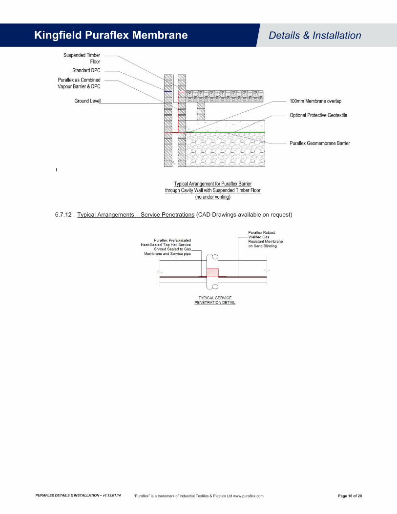
6.7.12 Typical Arrangements – Service Penetrations (CAD Drawings available on request)
Kingfield Puraflex Membrane Details & Installation
Page 16 of 20PURAFLEX DETAILS & INSTALLATION – v1.12.01.14 “Puraflex” is a trademark of Industrial Textiles & Plastics Ltd www.puraflex.com

7. APPENDIX 7.1 Defects and Repair Procedure
All welds and non-weld areas of the barrier membrane shall be inspected by the Inspector for defects, holes, blisters, un-dispersed raw materials, and any sign of contamination by foreign matter. The surface of the barrier membrane shall be clean at the time of inspection. Any lining surface showing injury due to scuffing, penetration by foreign objects, or distress from rough subgrade, shall be replaced or covered, and sealed with an additional layer of lining of the proper size, in accordance with the repair procedure.
7.1.1 Evaluation Each suspect location in weld and non-weld areas shall be non-destructively tested as appropriate in the presence of the Inspector. Each location that fails the non-destructive testing shall be marked by the Inspector, and repaired accordingly.
7.1.2 Repair Procedures Defective welds shall be patched or replaced. Pinholes and small holes shall be repaired by patching. Tears shall be repaired by patching. If the tear is on a slope or an area susceptible to stress and has a sharp end it must be rounded prior to patching. Blisters, large cuts and un-dispersed raw materials shall be repaired by patching. The patch shall be round or oval in shape made of the same barrier membrane and should extend at least 150mm outside the damaged area in order to ensure that the damaged area is covered completely. The patch should be prepared and welded using a hot air gun with a fishtail nozzle. The two surfaces to be welded are heated with the hot air gun until melting occurs on both surfaces. Pressure is then applied to the patch by means of a hand roller until the weld cools.
7.1.3 Verification of Repairs Each repair shall be non-destructively tested. Repairs that pass the non-destructive test shall be taken as an indication of an adequate repair. Failed tests indicate that the repair shall be repeated and retested until passing test results are achieved. The Inspector shall keep documentation of all non-destructive and destructive testing. This documentation shall identify all welds that initially failed the test and include evidence that these welds were repaired and successfully retested.
7.2 Welding Equipment Welding trials were carried out using a Leister Twinny-S hot air wedge welding machine with a maximum welding pressure of 500N at the nip, a maximum temperature of 600 ºC, a maximum traverse speed of 4m/min and a power rating of 1900W.
7.2.1 Summary of hot air wedge welding trials:
Sample No.
Temp Speed Pressure Roller Type1
Av. Max Load (N) ºC m/min Newtons start mid end
1 500 4.0 400
25mm knurled
single seam
157 163 160 2 475 160 162 163 3 450 158 155 152
i Smooth rollers tended to leave a rippled surface finish that may lead to a possibility of stresses being unevenly distributed leading to premature failure.
ii Trials using heated wedge machines determined that it was difficult to start the weld run and unsatisfactory joints were produced. This is a common problem with electrically heated wedge welding of thinner sheets because of the physical contact between the hot wedge and the material.
7.2.2 Welding equipment recommendations: Type: Hot air wedge welder, Leister Twinny-S or similar Roller: Single seam with 25mm knurled roller Initial Settings: Hot air temperature 450-500 ºC, approx. 4m/min at 400N These settings are recommended as a starting point when welding on site. Mechanical testing of ‘start-up’ trial welds should be carried out at the start of each day so that, depending upon site conditions, the appropriate machine adjustments can be made to ensure that a good weld is achieved.
Kingfield Puraflex Membrane Details & Installation
Page 17 of 20PURAFLEX DETAILS & INSTALLATION – v1.12.01.14 “Puraflex” is a trademark of Industrial Textiles & Plastics Ltd www.puraflex.com

7.3 Laboratory Testing of Welded Seams Laboratory testing of seam welds should be in accordance with BS EN 12814 Specimens should be 25mm wide x 150mm long and tested at a constant crosshead speed of 50mm/min until failure or excessive yield occurs. Independent laboratory test results of seam welds to BS EN 12814 are as follows:
Specimen No. 1 2 3 4 5 6 7 8 9 Mean Tensile Strength (N) 170.0 165.0 163.5 166.5 170.0 170.0 163.5 168.5 166.5 167.1
7.4 Weather Protection The two main elements that cause disruption to the installation are water and wind.
7.4.1 The only effective protection against rain is to utilise a tent or canopy when carrying out repairs or localised welding but in general, rain will bring to a halt all welding procedures. Membranes should not be deployed in areas of standing water. However, where there is standing water on the surface of the membrane it is possible to remove it by means of a pump, wet-vac or by a hand held squeegee. Dry cloths can then be used to dry the seam prior to welding.
7.4.2 Wind causes problems in two ways. i The membrane lifts once the wind gets under it and is impossible to control. Therefore, membrane
deployment should only take place during calm conditions. It is crucial that exposed membrane panels are ballasted immediately after deployment using sandbags or tyres, particularly in the area of the exposed edge. On embankments trout-lines are used to ballast membrane panels. Trout-lines are a line of sandbags (usually at one metre intervals) connected by a rope secured in an anchor trench at the top of the slope using an anchor pin.
ii It has the effect of decreasing the temperature of the hot air flow during welding. The only means of protecting against wind is to use a shield held in place by a technician directly in the path of the wind, just in front of the welding device.
The sun may also cause the membrane to wrinkle that can be a problem for welding. The top membrane expands more than the bottom membrane that leads to problems feeding the membrane through the welder drive rollers resulting in the welder burning through the material. Wherever possible, perimeter connections between embankments and flat areas should be carried out at the coolest time of the day or night when the membrane is fully contracted. This minimises the risk of causing a trampoline effect at this critical point.
Kingfield Puraflex Membrane Details & Installation
Page 18 of 20PURAFLEX DETAILS & INSTALLATION – v1.12.01.14 “Puraflex” is a trademark of Industrial Textiles & Plastics Ltd www.puraflex.com

Kingfield Puraflex Membrane Details & Installation
Page 19 of 20PURAFLEX DETAILS & INSTALLATION – v1.12.01.14 “Puraflex” is a trademark of Industrial Textiles & Plastics Ltd www.puraflex.com
7.5
Sam
ple
Fiel
d Se
am W
eld
Reco
rd
IN
STAL
LATI
ON
TE
ST
Dat
e Ti
me
Seam
R
ef.
Wel
der
Nam
e
Equi
pmen
t W
eath
er
Sam
ple
No.
ND
T Vi
sual
Insp
ectio
n Pe
el T
est
Pass
or F
ail
Insp
ectio
n
Mac
hine
R
ef. N
o
Hot
Air
Tem
p ºC
Mac
hine
O
pera
ting
Spee
d m
/min
Ambi
ent
Tem
p ºC
Win
d Sp
eed
m
/sec
Dat
e Pa
ss
or
Fail
Dat
e Ta
b 1
Tab
2 Ta
b 3
Tab
4 Ta
b 5
CQ
A N
ame
Kingfield Puraflex Membrane Details & Installation
Page 20 of 20PURAFLEX DETAILS & INSTALLATION – v1.12.01.14 “Puraflex” is a trademark of Industrial Textiles & Plastics Ltd www.puraflex.com
7.6 Useful References ASTM D 6392 - Standard Test Method for Determining the Integrity of Nonreinforced Geomembrane Seams Produced using Thermo-Fusion Methods BS EN 12814-4 - Testing of welded joints of thermoplastics semi-finished products. Peel test BS EN 13067 - Plastics Welding Personnel - Qualification testing of welders - thermoplastics welded assemblies BS EN 13719 - Determination of the long term protection efficiency of geotextiles in contact with geosynthetic barriers LFE2 - Cylinder testing geomembranes and their protective materials LFE4 - Earthworks on landfill sites LFE5 - Using geomembranes in landfill engineering LFE6 - Guidance on using landfill cover materials LFE7 - Using nonwoven protector geotextiles in landfill engineering LFE8 - Geophysical testing of geomembranes used in landfills Quality Assurance and Quality Control for Waste Containment Facilities (United States Environmental Protection Agency - USEPA). Waste Management Paper No. 26B, Landfill Design, Construction and Operational Practice
FURTHER INFORMATION For the latest technical information, please refer to the following publications which are available from our technical department or in digital format from our website (Registration required): Puraflex Brochure Product information detailing relevant standards and test methods, our comprehensive chemical resistance testing programme, production and quality assurance Puraflex Technical Briefing An technical summary of chemical resistance test methods and details of the science incorporated in Pura�ex’s barrier technology Puraflex Permeation Modelling (PPM) Software PPM is a unique software program which uploads soil analysis concentrations to report and provide permeation data of priority hydrocarbons and toxic industrial chemicals for incorporating in contaminated site risk assessment models (e.g. CLEA) Puraflex Product Data Comprehensive test data for mechanical, hydraulic, thermal, durability and chemical resistance to BS, EN, ISO and ASTM test methods Puraflex Model Specification Suggested specification to assist design engineers in the preparation of project documentation Puraflex Safety Information Control of Substances Hazardous to Health (COSHH) & Material Safety Data Sheets (MSDS)
LIMITED WARRANTY NOTICE Every reasonable effort is made to apply KINGFIELD CONSTRUCTION PRODUCTS (KCP) exacting standards both in the manufacture of our products and in the information which we issue concerning these products and their use. We warrant our products to be of good quality and will replace or, at our election, refund the purchase price of any products proved defective. Satisfactory results depend not only upon quality products, but also upon many factors beyond our control. Therefore, except for such replacement or refund, KCP MAKES NO WARRANTY OR GUARANTEE, EXPRESS OR IMPLIED, INCLUDING WARRANTIES OF FITNESS FOR A PARTICULAR PURPOSE OR MERCHANTABILITY, RESPECTING ITS PRODUCTS, and KCP shall have no other liability with respect thereto. Any claim regarding product defect must be received in writing within one (1) year from the date of shipment. No claim will be considered without such written notice or after the specified time interval. User shall determine the suitability of the products for the intended use and assume all risks and liability in connection there with. Any authorized change in the printed recommendations concerning the use of our products must bear the signature of the KCP Technical Manager.
This information and all further technical advice are based on KCP’s present knowledge and experience. However, KCP assumes no liability for providing such information and advice including the extent to which such information and advice may relate to existing third party intellectual property rights, especially patent rights. In particular, KCP disclaims all CONDITIONS AND WARRANTIES, WHETHER EXPRESS OR IMPLIED, INCLUDING THE IMPLIED WARRANTIES OF FITNESS FOR A PARTICULAR PURPOSE OR MERCHANTABILITY. KCP SHALL NOT BE RESPONSIBLE FOR CONSEQUENTIAL, INDIRECT OR INCIDENTAL DAMAGES (INCLUDING LOSS OF PROFITS) OF ANY KIND. KCP reserves the right to make any changes according to technological progress or further developments. It is the customer’s responsibility and obligation to carefully inspect and test any incoming goods. Performance of the product(s) described herein should be verified by testing and carried out only by qualified experts. It is the sole responsibility of the customer to carry out and arrange for any such testing. Reference to trade names used by other companies is neither a recommendation, nor an endorsement of any product and does not imply that similar products could not be used.
TECHNICAL SUPPORTPhone: +1 (612) 225-5167
Email: [email protected] in U.S.A.
KINGFIELD CONSTRUCTION PRODUCTSMinneapolis, Minnesotawww.kingfieldcp.com©2014 Kingfield Construction Products