Embed Size (px)
Citation preview

Kinetix 350 Single-axis EtherNet/IP Servo DrivesCatalog Numbers 2097-V31PR0-LM, 2097-V31PR2-LM, 2097-V32PR0-LM, 2097-V32PR2-LM, 2097-V32PR4-LM, 2097-V33PR1-LM, 2097-V33PR3-LM, 2097-V33PR5-LM, 2097-V33PR6-LM, 2097-V34PR3-LM, 2097-V34PR5-LM, 2097-V34PR6-LM
User ManualOriginal Instructions

Troubleshoot the Kinetix 350 Drive Chapter 7
Error Codes
The following list helps you resolve memory anomalies.
When a fault is detected, the status indicator displays an E and a two-digit error code until the anomaly is cleared.
Fault Codes
These fault code tables are designed to help you resolve anomalies. When a fault is detected, the four-digit status indicator scrolls the display message. The display is repeated until the fault code is cleared.
Table 44 - Fault Code Summary
ErrorCode
Anomaly Possible Cause Action/Solution
E38 Memory module error. Bad memory module. Replace memory module.
E76 Blank memory module. A Blank MEM module has been inserted into the drive.
Push and hold the drive's enter key (bottom most red button) on the drive's front display until the drive shows bUSY. This makes the drive format the blank memory module for usage with the drive.
Fault Code Type Description
S xxConditions that prevent the drive from enabling, see Table 45.
Scxx
F xxStandard axis fault, see Table 46 and Table 47.
Fcxx
LxxxUnrecoverable errors that occur during the boot process.Return drive to Rockwell Automation.
Pxxx Unrecoverable errors that occurred during the Power on Self Test (POST). Return drive to Rockwell Automation.
Icxx Anomalies that prevent normal operation and occur during the initialization process.
nFxx Anomalies that prevent normal operation of the drive. Node Fault. This type of fault that impacts the servo drive not just the axis of motion.
Table 45 - S xx and Scxx Start Inhibit Codes
Four-digit Display RSLogix 5000® and Logix Designer Fault Message Problem or Symptom Potential Cause Possible Resolution
S 01 Axis enable input. The axis enable input isdeactivated. Axis Enable Input is not active.
• Check wiring and 24V source for drive ENABLE Input.
• Disable enableInputChecking attribute by using a message instruction.
Rockwell Automation Publication 2097-UM002D-EN-P - April 2017 113

Chapter 7 Troubleshoot the Kinetix 350 Drive
S 02 Motor not configured. The associated motor has not been configured for use.
Faulty intelligent encoder or incorrect motor file.
• Cycle power or reset the drive.• Check that proper motor has been
selected in Logix Designer Application.
• Replace motor if faulting continues.S 03 Feedback not configured.
The associated feedback device has not been configured for use or the configuration does not match what is connected.
Sc05 Safe torque off. No power or safety circuitry not configured.
The safety function has disabled the power structure.
• Apply 24V sources to safety circuit.• Use jumpers to bypass safety circuit.
Table 46 - F xx Fault Codes
Four-digit Display RSLogix 5000 and Logix Designer Fault Message Problem or Symptom Potential Cause Possible Resolution
F 02 Illegal Hall State State of Hall feedback inputs is incorrect. Improper connections.• Check wiring of S1,S2, and S3• Check the power supply to the
encoder.
F 03 Motor Overspeed Motor speed has exceeded 125% of maximum rated speed.• Check motor wire phasing.• Check cables for noise.• Check tuning.
F 05 Motor Overtemperature
The motor thermostat, motor thermistor, or encoder temperature sensor indicates that the motor factory temperature limit has been exceeded.
High motor ambient temperature and/or Excessive Current.
• Check motor wiring at motor feedback (MF) connector.
• Check TS+ and COM wiring.• Operate within (not above) the
continuous torque rating for the ambient temperature.
• Lower ambient temperature or increase motor cooling.
• Verify that the proper motor has been selected.
F 07 Motor Thermal ProtectionThe thermal model for the motor indicates that the temperature has exceeded 110% of its rating.
The machine duty cycle requires an RMS current that exceeds the continuous rating of the motor.
Change the command profile to reduce speed or increase time.
F 10 Inverter Overcurrent
The drive fault output indicates that the power transistors were turned off because of overcurrent, overtemperature, or power supply problems.
Motor cables that are shorted. Verify continuity of motor power cable and connector.
Motor winding shorted internally.
Disconnect motor power cables from the motor. Use multimeter to check that the resistance of phase-to-phase is not open and that phase-to-ground is open.
The drive temperature is too high.
• Check for clogged vents or defective fan.
• Make sure that cooling is not restricted by insufficient space around the unit.
• Verify that ambient temperature is within the specification. See Kinetix 350 Drive Power Specifications in Kinetix Servo Drives Specifications Technical Data, publication KNX-TD003.
Operation above continuous power rating and/or product environmental ratings.
• Operate within the continuous power rating.
• Reduce acceleration rates.
The drive has a short circuit, overcurrent, or failed component.
Remove all power and motor connections, and perform a continuity check from the DC bus to the U, V, and W motor outputs. If a continuity exists, check for wire fibers between terminals, or send drive in for repair.
Loss of TTL signal Check AM+, AM -, BM +, and BM- signals.
Table 45 - S xx and Scxx Start Inhibit Codes (Continued)
Four-digit Display RSLogix 5000® and Logix Designer Fault Message Problem or Symptom Potential Cause Possible Resolution
114 Rockwell Automation Publication 2097-UM002D-EN-P - April 2017

Troubleshoot the Kinetix 350 Drive Chapter 7
F 11 Inverter Overtemperature Inverter thermal switch tripped.
Drive fan failed. Replace the failed drive.
The cabinet ambient temperature is above rating.
Check the cabinet temperature. See Kinetix 350 Drive Power Specifications in Kinetix Servo Drives Specifications Technical Data, publication KNX-TD003
The machine duty cycle requires an RMS current that exceeds the continuous rating of the controller.
Change the command profile to reduce speed or increase time.
The airflow access to the drive system is limited or blocked.
Check airflow and reroute cables away from the drive system.
F 13 Inverter Thermal ProtectionThe thermal model for the power transistors indicates that the temperature has exceeded 110% of its rating.
The machine duty cycle requires an RMS current that exceeds the continuous rating of the controller.
Change the command profile to reduce speed or increase time.
Motor brake on. Turn off motor brake.
F 33 Bus Undervoltage With three-phase power present, the DC bus voltage is below limits.
DC bus voltage for 460V system is below 275V.DC bus voltage for 230V system is below 137V.DC bus voltage for 120V system is below 80V
• Verify voltage level of the incoming AC power.
• Check AC power source for glitches or line drop.
• Install an uninterpretable power supply (UPS) on your AC input.
F 35 Bus Overvoltage The DC bus voltage is measured above a factory limit.
Excessive regeneration of power. Change the deceleration or motion profile.
When the motor is driven by an external mechanical power source, it can regenerate too much peak energy through the drive power supply. The system faults to save itself from an overload.
Use a larger system (motor and drive).
DC bus voltage for 460Vsystem is over 820V.
Install shunt resistor.
F 43 Feedback Loss
• On sin/cos encoders, the sum of the square of the sin/cos signals has been measured below a factory limit.
• On TTL encoders, the absolute value of the differential A/B signals is below a factory limit.
The motor feedback wiring is open, shorted, or missing.
• Check motor encoder wiring.• Run Hookup test in RSLogix 5000
software.
F 45Feedback Serial Comms(only TL-Series™ motors and actuators)
The number of consecutive missed or corrupted serial data packets from the feedback device has exceeded a factory set limit.
Communication was not established with an intelligent encoder.
• Verify motor selection.• Verify motor encoder wiring.
F 47 Feedback Self Test The feedback device has detected an internal error. Damage to feedback device. Call your Rockwell Automation sales
representative to return motor for repair.
F 50 Hardware Overtravel - Positive Axis that is moved beyond the physical travel limits in the positive direction. Dedicated overtravel input is
inactive.
• Check wiring.• Verify motion profile.• Verify axis configuration in software.F 51 Hardware Overtravel - Negative Axis that is moved beyond the physical travel
limits in the negative direction.
F 54 Excessive Position Error Position error limit was exceeded.
Partial loss of feedback signals. Check all wiring at motor feedback (MF) connector.
Improperly sized drive or motor. Verify sizing of system.
Mechanical system out of specifications.
• Increase the feed forward gain.• Increase following error limit or
time.• Check position loop tuning.• Verify mechanical integrity of
system within specification limits.• Check motor power wiring.
Table 46 - F xx Fault Codes (Continued)
Four-digit Display RSLogix 5000 and Logix Designer Fault Message Problem or Symptom Potential Cause Possible Resolution
Rockwell Automation Publication 2097-UM002D-EN-P - April 2017 115

Chapter 7 Troubleshoot the Kinetix 350 Drive
F 55 Excessive Velocity ErrorVelocity Error value of the velocity control loop has exceeded the configured value for Velocity Error Tolerance.
Partial loss of feedback signals. Check all wiring at motor feedback (MF) connector.
Improperly sized drive or motor.• Increase velocity error limit or time.• Check velocity loop tuning.• Verify sizing of system.
Mechanical system out of specifications.
• Increase velocity error limit or time.• Check velocity loop tuning.• Verify mechanical integrity of
system within specification limits.• Check motor power wiring.• Reduce acceleration.
F 56 Overtorque Limit Motor torque has exceeded a user-programmable setting.
• Overly aggressive motion profile.
• Mechanical binding.
• Verify motion profile.• Verify that Overtorque settings are
appropriate.• Verify sizing of system.• Verify torque offset
Mechanical system out of specifications.
Verify mechanical integrity of system within specification limits.
F 57 Undertorque Limit Motor torque has fallen below a user-programmable setting.
• Improperly configured limit.• Improperly configured
motion.• Improperly drive/motor
sizing.
• Verify motion profile.• Verify that Overtorque settings are
appropriate.• Verify sizing of system.
Mechanical system out of specifications.
Verify mechanical integrity of system within specification limits.
F 61 Drive Enable InputThe hardware enable input was deactivated while the drive was enabled. This is applicable when only drive enable input is used.
An attempt was made to enable the axis through software while the Drive Enable hardware input was inactive.
• Check wiring of drive enable input.• Check 24V source.
The Drive Enable input that has transitioned from active to inactive while the axis was enabled.
Verify that Drive Enable hardware input is active whenever the drive is enabled through software.
F 62 Controller Initiated Exception The controller has requested the drive to generate an exception.
User configured software overtravel.
• Move axis out of soft overtravel range.
• Clear soft overtravel fault.• Check soft overtravel configuration.• Consult controller documentation.
Table 47 - Fc xx Fault Codes
Four-digit Display RSLogix 5000 and Logix Designer Fault Message Problem or Symptom Potential Cause Possible Resolution
Fc 02 Motor Voltage Mismatch Motor voltage incompatible with drive voltage. Wrong motor has been connected to drive. Connect appropriate motor to drive.
Fc 05Motor Encoder Battery Loss(applies to Bulletin TLY motors with B feedback)
The battery voltage on a battery-backed motor encoder is low enough such that a power loss has caused the absolute position to be no longer available. Weak battery or poor battery
connection.• Replace battery.• Check battery connection.
Fc 06Motor Encoder Battery Low(applies to Bulletin TLY motors with B feedback)
The battery voltage on a battery-backed motor encoder is low enough such that a power loss causes the absolute position to be lost.
Fc 14 Excessive Current Feedback Offset Current in one or more phases have been lost or remains below a preset level. Replace the drive.
Fc 26 Runtime Drive Error The drive firmware encountered an unrecoverable runtime error.• Cycle control power.• Replace drive.
Table 46 - F xx Fault Codes (Continued)
Four-digit Display RSLogix 5000 and Logix Designer Fault Message Problem or Symptom Potential Cause Possible Resolution
116 Rockwell Automation Publication 2097-UM002D-EN-P - April 2017

Troubleshoot the Kinetix 350 Drive Chapter 7
Status messages of the format Lxxx indicate an unrecoverable error while starting the drive. Reload firmware and restart the drive, if status message repeats contact Rockwell Automation technical support to return drive for repair.
Status messages of the format Pxxx indicate an unrecoverable error during the Power-on Self Test (POST). Contact Rockwell Automation technical support to return drive for repair.
Table 48 - Ic xx Fault Codes
Four-digit Display RSLogix 5000 and Logix Designer Fault Message Problem or Symptom Potential Cause Possible Resolution
Ic 01 Boot Block Check Sum Fault The motor data that is stored in a smart encoder has a checksum error. Faulty intelligent encoder.
• Cycle power or reset the drive.• Replace motor if faulting continues.
Ic 02 Motor Data Range Error Data within a motor data blob is out of range. Faulty intelligent encoder or incorrect motor file.
• Cycle power or reset the drive.• Check validity of the motion
database. • Replace motor if faulting continues.
Ic 03 Motor Feedback Communication Startup
Communication with a smart encoder could not be established on the motor feedback port.
An incorrect motor has beem selected or connected. Check motor selection.
Faulty wiring. Check motor encoder wiring.
Ic 06 Motor Absolute Startup SpeedThe motor absolute encoder was not able to determine the position after powerup due to motor speed greater than 100 rpm.
Mechanical movement of machine has caused excessive rotation of motor during powerup.
Allow machine motion to stop before powerup.
Table 49 - Lxxx Fault Codes
Four-digitDisplay Message Cause
L001 Identity block corrupted
L002 Firmware file load failed
L004 Firmware not programmed (drive is new)
L008 DSP load operation failed
Table 50 - Pxxx Fault Codes
Four-digitDisplay Message Cause
P001 SDRAM test failed
P002 FPGA load operation failed
P004 DPRAM Test failed
P005 DSP I/F to DPram - no DSP response
P006 I/F to DPram failed
P007 Firmware file md5 test failure
Rockwell Automation Publication 2097-UM002D-EN-P - April 2017 117
Chapter 7 Troubleshoot the Kinetix 350 Drive
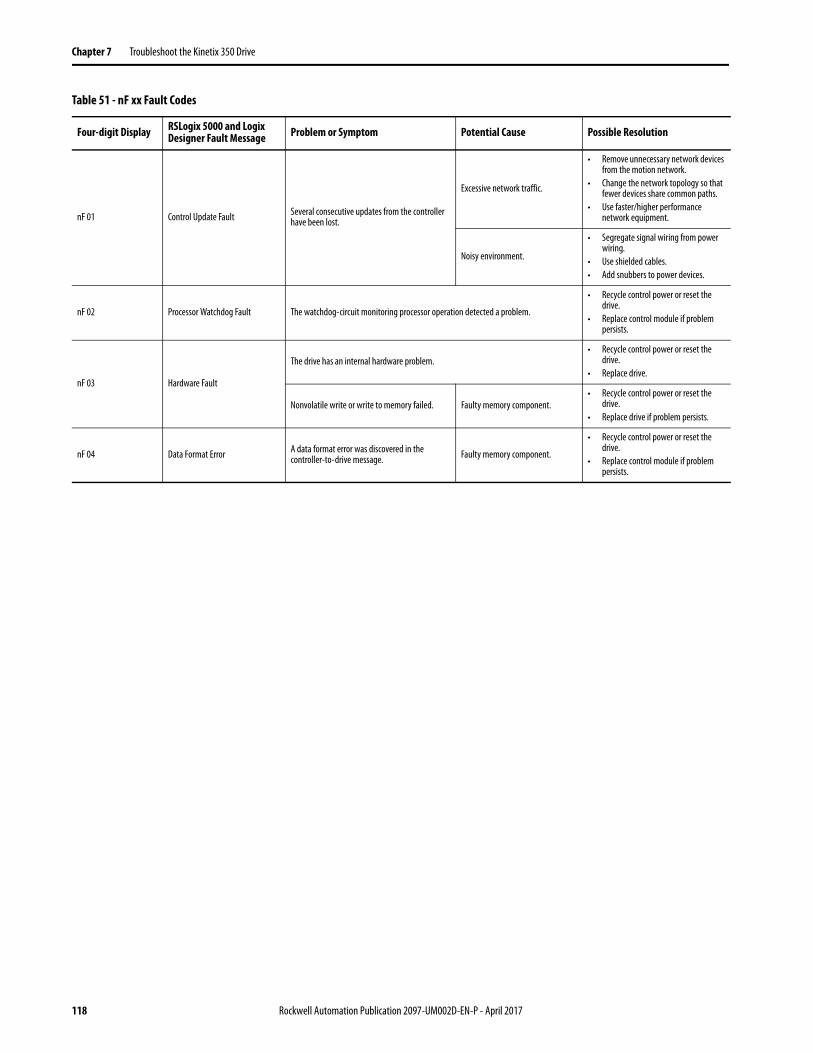
Table 51 - nF xx Fault Codes
Four-digit Display RSLogix 5000 and Logix Designer Fault Message Problem or Symptom Potential Cause Possible Resolution
nF 01 Control Update Fault Several consecutive updates from the controller have been lost.
Excessive network traffic.
• Remove unnecessary network devices from the motion network.
• Change the network topology so that fewer devices share common paths.
• Use faster/higher performance network equipment.
Noisy environment.
• Segregate signal wiring from power wiring.
• Use shielded cables.• Add snubbers to power devices.
nF 02 Processor Watchdog Fault The watchdog-circuit monitoring processor operation detected a problem.
• Recycle control power or reset the drive.
• Replace control module if problem persists.
nF 03 Hardware Fault
The drive has an internal hardware problem. • Recycle control power or reset the
drive. • Replace drive.
Nonvolatile write or write to memory failed. Faulty memory component.• Recycle control power or reset the
drive. • Replace drive if problem persists.
nF 04 Data Format Error A data format error was discovered in the controller-to-drive message. Faulty memory component.
• Recycle control power or reset the drive.
• Replace control module if problem persists.
118 Rockwell Automation Publication 2097-UM002D-EN-P - April 2017

Troubleshoot the Kinetix 350 Drive Chapter 7
Status Indicators
Table 52 - Drive Status Indicator
Table 53 - Axis Status Indicator
Status Description
Off No power. Apply power.
Alternating green/red Self-test (power-up diagnostics). Wait for steady green.
Flashing green Standby (device not configured). Wait for steady green.
Steady green Normal operation, no faults.
Flashing red Minor fault (recoverable). See four-digit fault message.
Steady red Major fault (non-recoverable). See four-digit fault message.
Status Description
Off Off
Flash red/green Self test
Off Initialization - bus not up
Flashing green Initialization - bus up
Off Shutdown - bus not up
Flashing amber (1)
(1) The axis and the drive define minor fault conditions. While a minor fault does not affect the drive status indicator, it does affect the axis status indicator. When a minor fault condition is detected, a normally solid-green status indicator indication changes to alternating red-green-red-green, a normally flashing green status indicator indication changes to alternating red-off-green-off, and a normally flashing amber indications changes to red-off-amber-off.
Shutdown - bus up
Off Pre-charge - bus not up
Flashing amber (1) Start inhibit
Flashing green (1) (2)
(2) The drive also defines alarm conditions. When an alarm condition is detected, a normally solid-green status indicator indication changes to alternating amber-green-amber green while a normally flashing green status indicator indication changes to alternating amber-off-green-off.
Stopped
Solid green (1) (2)
Stopping
Starting
Running
Testing
Flashing redAborting
Major faulted
Solid redAborting
Major faulted
Rockwell Automation Publication 2097-UM002D-EN-P - April 2017 119

Chapter 7 Troubleshoot the Kinetix 350 Drive
Table 54 - Network Status Indicators
Table 55 - Port 1 Ethernet Communication Status Indicators
General System Behavior These events do not always result in a fault code, but can require troubleshooting to improve performance.
Status Description
Off No power or no IP address defined.
Alternating green/red Self-test mode (power-up diagnostics).
Flashing green Standby (device that is not configured, or connection not established).
Steady green Normal operation. Device has at least one established connection.
Flashing red Recoverable minor fault or connection timeout.
Steady red Non-recoverable major fault or duplicate IP address.
IMPORTANT Under some fault conditions, two reset commands can be required to clear drive.
Status Description
Off No link partner present.
Flashing green Link partner present, communication occurring.
Steady green Link partner present, no communication occurring.
Table 56 - General System Behavior
Condition Potential Cause Possible Resolution
Axis or system is unstable.
The position feedback device is incorrect or open. Check wiring.
Unintentionally in Torque mode. Check to see what primary operation mode was programmed.
Motor tuning limits are set too high. Run Tune in RSLogix 5000 software.
Position loop gain or position controller accel/decel rate is improperly set. Run Tune in RSLogix 5000 software.
Improper grounding or shielding techniques are causing noise to be transmitted into the position feedback or velocity command lines, causing erratic axis movement.
Check wiring and ground.
Motor Select limit is incorrectly set (servo motor is not matched to axis module). • Check setups.• Run Tune in RSLogix 5000 software.
Mechanical resonance.Notch filter or output filter can be required (refer to Axis Properties dialog box, Output tab in RSLogix 5000 software).
120 Rockwell Automation Publication 2097-UM002D-EN-P - April 2017