Embed Size (px)
Citation preview

University of Nebraska - LincolnDigitalCommons@University of Nebraska - Lincoln
USGS Staff -- Published Research US Geological Survey
1995
Kinetics of pressure solution at halite-silicainterfaces and intergranular clay filmsStephen H. HickmanU.S. Geological Survey
Brian EvansMassachusetts Institute of Technology
Follow this and additional works at: http://digitalcommons.unl.edu/usgsstaffpub
Part of the Earth Sciences Commons
This Article is brought to you for free and open access by the US Geological Survey at DigitalCommons@University of Nebraska - Lincoln. It has beenaccepted for inclusion in USGS Staff -- Published Research by an authorized administrator of DigitalCommons@University of Nebraska - Lincoln.
Hickman, Stephen H. and Evans, Brian, "Kinetics of pressure solution at halite-silica interfaces and intergranular clay films" (1995).USGS Staff -- Published Research. 411.http://digitalcommons.unl.edu/usgsstaffpub/411

JOURNAL OF GEOPHYSICAL RESEARCH, VOL. 100, NO. B7, PAGES 13,113-13,132, JULY I0, 1995
Kinetics of pressure solution at halite-silica interfaces and intergranular clay films
Stephen H. Hickman U.S. Geological Survey, Menlo Park, California
Brian Evans
Department of Earth, Atmospheric, and Planetary Sciences, Massachusetts Institute of Technology, Cambridge
Abstract. Pressure solution is widely regarded as a potentially important deformation mechanism along crustal faults and during aliagenesis, yet the mechanisms and kinetics of this process remain highly controversial. To better understand the fundamental factors controWing the rates of pressure solution at the grain-to-grain scale, we conducted experiments in which convex halite lenses were pressed against fiats of fused silica in brine. Fluid pressures were maintained at 0.1 MPa; temperatures and mean contact normal stresses ranged from 8.3 ø to 90.2øC and 0.5 to 13.5 MPa, respectively. The geometry and growth rate of the contact spot between the two lenses and the rate at which the lenses approached one another (convergence) were monitored using reflected light interferometry and transmitted light photomicrography. Convergence occurred when halite and silica lenses were pressed together in brine (halite/silica experiments). No undercutting was observed, and dry control experiments indicated negligible dislocation creep. Convergence rates in experiments at 50.2øC ranged from 0.01 to 0.05/•m/d, depending on mean normal stress and contact spot radius. The data are consistent with intergranular pressure solution (IPS) rate-limited by diffusion through an intergranular film with a very high diffusion coefficient (• 10 -5- 10 -7 cm2/s). The data further suggest that the diffusion coefficient and/or thickness of this film increases with decreasing normal stresses, at least for normal stresses less than about 4 MPa. As no island-channel boundary structures were observed, we propose that this film consists of a continuous layer of strongly adsorbed (i.e., structured) water that is maintained between the halite and silica lenses during deformation. Convergence rates in similar experiments conducted at a constant load of 0.11 N but at 8.3 ø, 50.2 ø, and 90.2øC were approximately constant at a given normal stress and contact spot size. The cause of this temperature insensitivity is unknown but might result from changes in interphase boundary structure or thickness with increasing temperature that are sufficient to offset the expected thermal activation. An experiment was also conducted in which a halite lens was pressed against a fused silica fiat coated with an 0.8-/•m-thick film of Na-montmorillonite in brine. This clay film produced an approximately fivefold increase in convergence rates over those observed in a halite/ silica experiment conducted without clay at the same load and temperature. The strong sensitivity of IPS rates both to contact spot radius and to the presence of second phases along grain boundaries suggests that fine-grained, clay-rich fault gouges and multiphase granular aggregates should be particularly susceptible to pressure solution creep in the middle to upper crust.
Introduction
Fluids profoundly affect fault deformation by mechanisms that are both chemical and physical in nature. Stress corro- sion cracking, pore fluid diffusion, and dilatancy hardening on faults may delay sliding instability [Rudnicki, 1988]. The influx of deep fluids [Rice, !992], the duerite creep compac- tion of porous rocks [Sleep and Blanpied, 1992], or the intrinsically low permeability of clays [Byeflee, 1990] might cause or permit high pore fluid pressures and reduce fric-
Copyright 1995 by the American Geophysical Union.
Paper number 95JB0091 !. 0148-0227/95/95JB-009 ! 1 $05.00
tional strength during seismic events. Compaction of fault rocks could also occur by fracturing [Wong, 1990]. Chemical processes such as cementation, sealing, and lithification can indurate and strengthen fault rocks, reduce the permeability of the fault and its surroundings, or increase the elastic stiffness of the fault zone [Angerinc et al., 1982; Chester and Logan, 1986; Fredrich and Evans, 1992].
Pressure solution may be a particularly important defor- mation mechanism in the fine-grained rocks and gouges along faults. This process, which involves dissolution of material at grain-to-grain contacts under high stress and the precipitation of that material at interfaces under low stress [Tada et al., 1987], could reduce long-term strength and
13,!13
13,114 HICKMAN AND EVANS: HALITE PRESSURE SOLUTION
f xx., ; f
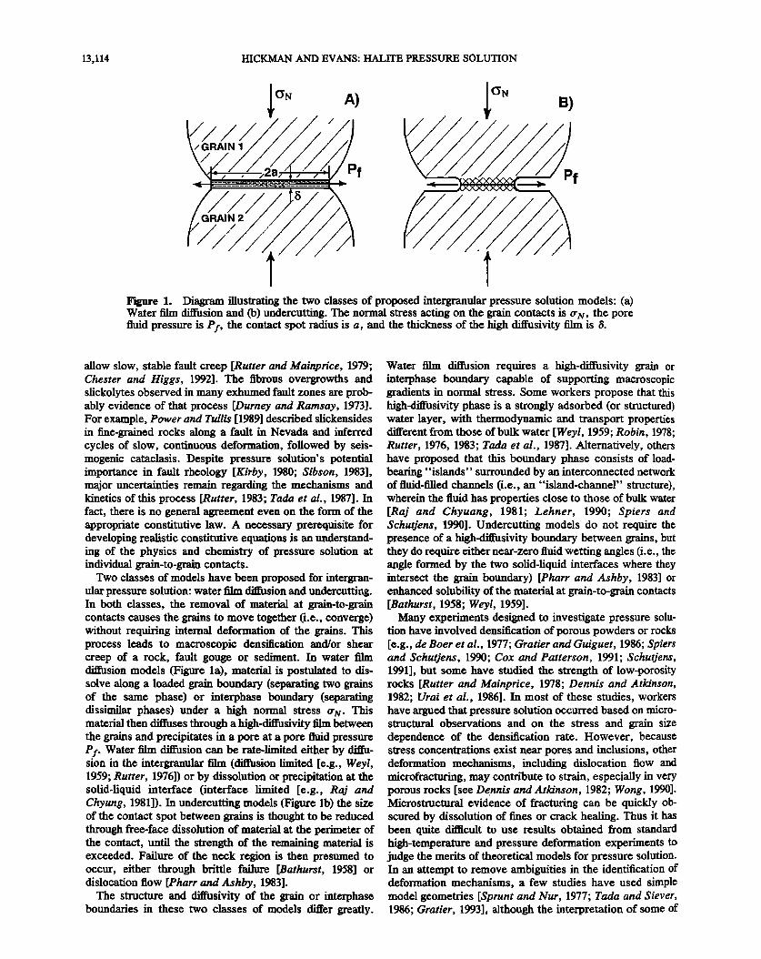
Figure 1. Diagram illustrating the two classes of proposed intergranular pressure solution models: (a) Water film diffusion and (b) undercutting. The normal stress acting on the grain contacts is (r•v, the pore fluid pressure is Pf, the contact spot radius is a, and the thickness of the high diffusivity film is/5.
allow slow, stable fault creep [Rutter and Mainprice, 1979; Chester and Higgs, 1992]. The fibrous overgrowths and slickolytes observed in many exhumed fault zones are prob- ably evidence of that process [Durney and Ramsay, 1973]. For example, Power and Tullis [1989] described slickensides in fine-grained rocks along a fault in Nevada and inferred cycles of slow, continuous deformation, followed by seis- mogenic cataclasis. Despite pressure solution's potential importance in fault rheology [Kirby, !980; Sibson, 1983], major uncertainties remain regarding the mechanisms and kinetics of this process [Rutter, 1983; Tada et al., 1987]. In fact, there is no general agreement even on the form of the appropriate constitutive law. A necessary prerequisite for developing realistic constitutive equations is an understand- ing of the physics and chemistry of pressure solution at individual grain-to-grain contacts.
Two classes of models have been proposed for intergran- ular pressure solution: water film diffusion and undercutting. In both classes, the removal of material at grain-to-grain contacts causes the grains to move together (i.e., converge) without requiring internal deformation of the grains. This process leads to macroscopic densification and/or shear creep of a rock, fault gouge or sediment. In water film diffusion models (Figure la), material is postulated to dis- solve along a loaded grain boundary (separating two grains of the same phase) or interphase boundary (separating dissimilar phases) under a high normal stress (r•v. This material then diffuses through a high-diffusivity film between the grains and precipitates in a pore at a pore fluid pressure Pf. Water film diffusion can be rate-limited either by diffu- sion in the intergranular film (diffusion limited [e.g., Weft, 1959; Rutter, 1976]) or by dissolution or precipitation at the solid-liquid interface (interface limited [e.g., Raj and Chyung, 1981]). In undercutting models (Figure lb) the size of the contact spot between grains is thought to be reduced through free-face dissolution of material at the perimeter of the contact, until the strength of the remaining material is exceeded. Failure of the neck region is then presumed to occur, either through brittle failure [Bathurst, 1958] or dislocation flow [Pharr and Ashby, 1983].
The structure and diffusivity of the grain or interphase boundaries in these two classes of models differ greatly.
Water film diffusion requires a high-diffusivity grain or interphase boundary capable of supporting macroscopic gradients in normal stress. Some workers propose that this high-diffusivity phase is a strongly adsorbed (or structured) water layer, with thermodynamic and transport properties different from those of bulk water [Weyl, 1959; Robin, !978; Rutter, 1976, 1983; Tada et al., 1987]. Alternatively, others have proposed that this boundary phase consists of load- beating "islands" surrounded by an interconnected network of fluid-filled channels (i.e., an "island-channel" structure), wherein the fluid has properties close to those of bulk water [Raj and Chyuang, 1981; Lehner, 1990; Spiers and Schutjens, 1990]. Undercutting models do not require the presence of a high-diffusivity boundary between grains, but they do require either near-zero fluid wetting angles (i.e., the angle formed by the two solid-liquid interfaces where they intersect the grain boundary) [Pharr and Ashby, 1983] or enhanced solubility of the material at grain-to-grain contacts [Bathurst, 1958; Weyl, 1959].
Many experiments designed to investigate pressure solu- tion have involved densification of porous powders or rocks [e.g., de Boer et al., 1977; Gratier and Guiguet, 1986; Spiers and Schutjens, 1990; Cox and Patterson, 1991; Schutjens, 19911, but some have studied the strength of low-porosity rocks [Rutter and Mainprice, 1978; Dennis and Atkinson, 1982; Urai et al., 1986]. In most of these studies, workers have argued that pressure solution occurred based on micro- structural observations and on the stress and grain size dependence of the densification rate. However, because stress concentrations exist near pores and inclusions, other deformation mechanisms, including dislocation flow and microfracturing, may contribute to strain, especially in very porous rocks [see Dennis and Atkinson, 1982; Wong, !990]. Microstructural evidence of fracturing can be quickly ob- scured by dissolution of fines or crack healing. Thus it has been quite difficult to use results obtained from standard high-temperature and pressure deformation experiments to judge the merits of theoretical models for pressure solution. In an attempt to remove ambiguities in the identification of deformation mechanisms, a few studies have used simple model geometries [Sprunt and Nur, 1977; Tada and Siever, 1986; Gratier, 1993], although the interpretation of some of

HICKMAN AND EVANS: HALITE PRESSURE SOLUTION 13,115
MICROSCOPE
NEOPRENE
GASKET
.-.-.-.-...-.-....
QUARTER-WAVE PLATE
IMMERSION OIL
WATER OUT
BRINE INLET/
OUTLET PORTS
WATER IN
•RM!STOR SPRING I I
0-RING
•] FUSED SILICA r---• BRASS
TEFLON
SAMPLE BRINE
DISTILLED WATER
INSULATING JACKET NOT SHOWN
Figure 2. Schematic of the heated microscope stage used in this study. The sample, spring, and stagnant bhne are contained within a cylindrical teflon and fused-silica chamber which is surrounded on all sides by circulating water from a constant-temperature bath. Loads are adjusted using fused-silica spacers placed in the sample column. The temperature of the circulating fluid is continuously recorded using a thermistor and checked periodically with a precision thermometer inserted into the water outlet line. When viewing the sample with reflected sodium light, a quarter wave plate is mounted on the upper window of the stage and the sample viewed under crossed polars to eliminate reflections from the upper window.
these experiments is still controversial [Bosworth, 1981; Green, 1984; Gratier, 1993].
Recently, Hickman and Evans [1991, 1992] studied defor- mation at the contact between single-crystal halite and fused silica lenses of carefully controlled shape, which were im- mersed in brine. By observing the model geometry while under load, they were able to distinguish between mecha- nisms which caused deformation at the contact and those
which only caused the growth of the contact zone. When a convex halite lens was pressed against a flat halite lens, no convergence occurred. However, the contact area between the lenses grew as halite dissolved from the free surfaces of the lenses, diffused through the pore fluid, and precipitated at the perimeter of the contact spot. This process, called neck growth, is analogous to crack healing and is driven by gradients in surface curvature [Hickman and Evans, 1992]. In similar experiments with a halite crystal pressed against a flat silica surface, convergence by intergranular pressure solution did occur. Deformation by cataclasis could be ruled out by careful observation of the surfaces and contact region during deformation.
In this paper, we present results from two suites of experiments conducted using halite and fused silica lenses in the same geometry employed in our earlier studies but in which load and temperature were independently varied. In this manner, we were able to study the kinetics of intergran- ular pressure solution (IPS) at the halite/silica contacts in greater detail. To investigate the effect that intergranular clays might have upon IPS rates, we also present results
from an experiment in which a convex halite lens was pressed against a fused silica flat coated with montmorillon- ite in brine. The results are a direct experimental confirma- tion of the enhancement of IPS at intergranular clay films, which is often observed in field studies [e.g., Tada and Siever, 1989].
Technique In these experiments, convex halite lenses were pressed
against flat silica disks in a heated microscope stage (Figure 2). We review the technique briefly here; additional details are given by Hickman [1989] and Hickman and Evans [1991, 1992]. To begin each experiment, •he halite/silica samples, a spring, and fused silica spacers were preheated and then immersed in saturated brine inside a Teflon chamber, which
was surrounded by a constant temperature bath. Special care was taken to ensure that the temperature within the sample chamber was spatially uniform •,to within 0.02øC) and constant in time (within 0.2øC during an experiment) and that the brine was completely saturated [see Hickman and Evans, 1991].
Loads were applied using creep- and corrosion-resistant Hastelloy C springs and were deliberately kept small to avoid fracture and minimize dislocation creep. The exact loads were calculated from precise measurements of sample chamber depth and sample heights using spring calibration curves; spring compression was adjusted to the desired value using fused silica spacers. The calculated loads were

13,116 HICKMAN AND EVANS: HALITE PRESSURE SOLUTION
corrected for thermal expansion of the springs, samples, spacers, and sample chamber and for changes in the elastic constants of Hastelloy C. Spring calibrations were checked repeatedly using a dead weight loading jig equipped with a micrometer touch point indicator, but no changes in calibra- tion were ever observed. Samples were weighed before and after each experiment (to ensure that the brine introduced into the sample chamber was not oversaturated or undersat- urated) and their dimensions were measured using a micro- scope equipped with a dial indicator.
In experiments at or below 50øC, brine was added directly to the contact spot using a temperature-controlled glass syringe before the chamber lid was closed (i.e., fabricated we0 [see Hickman and Evans, 1991]. In the two experiments at 90øC, however, this technique could not be used owing to rapid evaporation of the brine. In those cases, the lid to the sample chamber was closed first, the heated microscope stage was tilted on its side, and the brine was injected into the sample chamber through the lower brine inlet port (i.e., fabricated dry; see Figure 2).
Sample Preparation
The method of sample preparation was important [see Hi&man and Evans, 1991]. Standard abrasive polishing produced thick damage layers on the halite surface that caused roughening when the lenses were exposed to brine. Thus the samples used here were prepared by cleaving a blank from a single crystal of optical-grade, synthetic NaC1 (Harshaw Chemical Company), dissolving this blank to the appropriate size and curvature using porous polymer laps wetted with distilled water, polishing with 0.1-/•m alumina grit in isobutyl alcohol using an automatic lens-polishing machine, and baking in air at 650øC for 14 hours. All lenses were polished parallel to [001].
Montmorillonite was used in the halite/clay/silica experi- ment because of its capacity for adsorbing interlamellar and surface water, even while under high compressive stresses [e.g., Viani et al., 1983]. The Na-montmorillonite film was prepared using standard techniques for preparing basal- oriented clay films for X ray analysis [e.g., Gibbs, 1965]. Montmorillonite from Polksville, Mississippi (Clay Mineral Standard, API #21, Wards Scientific Company), was ultra- sonically disaggregated and soaked in NaCI brine for about !8 hours to saturate the exchangable cation sites with sodium. This suspension was repeatedly centrifuged, and the clear brine was decanted and replaced with distilled deion- ized water until flocculation ceased, allowing a fraction with grain size <0.5 /•m to be isolated by Stoke's settling. A dilute suspension of this size fraction was centrifuged onto a fused silica disk, and the disk was dried at about 40øC. The sides and bottom of the disk were wiped clean, and the disk was weighed and stored in a dessicator until the experiment. Comparing the weights of the silica disk before and after clay deposition and using a density of 2.5 g/cm 3 for montmoril- lonite indicated that the clay film was about 0.8 ___ 0.2 thick.
Measurement of Deformation at the Contact
Convergence was measured using time-lapse photography in reflected sodium light, wherein rays reflected from the disc/brine and brine/lens interfaces produce a concentric pattern of alternating light and dark interference fringes (termed Newton's rings) around the central contact. The
distance h between the two lenses can be determined at any distance r from the center of contact using [e.g., Rossi, 1957]:
h(r) = rnX/2nz), (1)
where rn is the order of an interference minimum (i.e., a dark Newton's ring), i is the wavelength of sodium light in a vacuum, and nz) is the refractive index of saturated brine for sodium light. We measured no at run temperatures using a refractometer connected to a constant-temperature bath [Hickman, 1989]. All of the samples exhibited some compo- nent of instantaneous convergence as the load was being applied, due primarily to plastic deformation (i.e., disloca- tion glide) within the halite lens (see below). The amount of time-dependent convergence that occurred after loading was determined by monitoring the change in either radius or area of the first 10 interference minima surrounding the contact spot and using the following relationships [Hickman and Evans, 1991]:
As = Ar 2m/2R L (2) and
AS = AA m/2 •rRL (3)
where As is the time-dependent (creep) component of con- vergence; Arm and AAm are the change in radius and the change in enclosed area of the mth order fringe relative to their values immediately following loading, respectively; and R•; is the radius of curvature of the convex (halite) lens. To minimize distortion, r m and A rn were measured by project- ing the interferograms directly onto a digitizing table. Plots of rn against rrn or A rn were used to determine R•;. The mean convergence As was then obtained as the mean and standard deviation of values determined independently for each fringe. With the exception of the halite/clay/silica experi- ment and halite/silica experiment PSH 34, equation (3) was used to determine convergence in all of these experiments.
Contact Area and Mean Normal Stress
Contact area A0 was determined by tracing the innermost indication of reflected sodium light on interferograms pro- jected onto a digitizing table. Uncertainties in contact area were conservatively estimated as the difference between the measured contact area and the area enclosed midway be- tween the contact border and the first. interference maxi- mum. The actual precision is considerably better than this. The equivalent contact spot radius a was defined as the radius of a circle whose area is equal to that of the actual contact. As the contacts in all of our experiments, with the exception of PSH 28 (see below), were very close to circular in form, this provides a representation of the contact size that is sufficiently accurate for our analysis. The mean normal stress P m is simply the applied load L divided by A0. (We subtracted the weight of the lower lens and underlying fused silica disk from the calculated spring force.) The spring loads were superposed on the fluid pressure, and so P rn as calculated here is the effective normal stress (i.e., normal stress minus fluid pressure).
Modified Tukon Tester
To provide information on the deformation which occurs during initial loading, we modified a Tukon indentation

HICKMAN AND EVANS' HALITE PRESSURE SOLUTION 13,117
LOAD
INDENTER MOUNT
COMPLIANT BACKING
HALITE LENS
, • FUSED SILICA ! "[/)3,?///5//.•.-- Ri G! D SUPPORT
INVERTED
MICROSCOPE
Figure 3. Schematic of the modified Tukon hardness tester apparatus used to measure the variation in mean contact stress with load for a halite convex lens pressed against a fused silica flat. The halite lens was mounted on a compliant backing in order to distribute the load evenly across the flat side of the lens.
hardness apparatus (Figure 3) to measure Prn as a function of load. A halite lens was prepared using the same procedure as before. The hardness tester was adjusted to lower this lens onto a fused silica fiat from a height of about 1 mm in approximately 40 s. The contact spot was then photographed under reflected sodium light after a contact time of 2 min.
Results
Halite/Silica Experiments in the Heated Microscope Stage
Seven experiments were conducted in which halite and silica lenses were pressed together in brine at temperatures of 8.3ø-90.2øC and loads of 0.11-4.22 N (Table 1). Uncer- tainties indicated for temperature are the maximum excur- sions recorded by a thermistor (Figure 2); uncertainties in load correspond to cumulative uncertainties in spring deflec- tion and calibration. To ascertain the contribution of dislo-
cation creep to convergence, halite and silica lenses were also pressed together in dry nitrogen at 50.2øC (PSH 18) and 90.5øC (PSH 30) and in moist air at 23ø-89.9øC (PSH 34). Except for a power failure during PSH 31 and the room temperature portion of PSH 34, the maximum temperature excursions ranged from +-0.07 ø to _+0.20øC. Fortunately, the power failure in PSH 31 had no apparent effect upon the surface topography, contact spot size or convergence rate; nor was there a discernible change in sample weight [see Hickman, 1989].
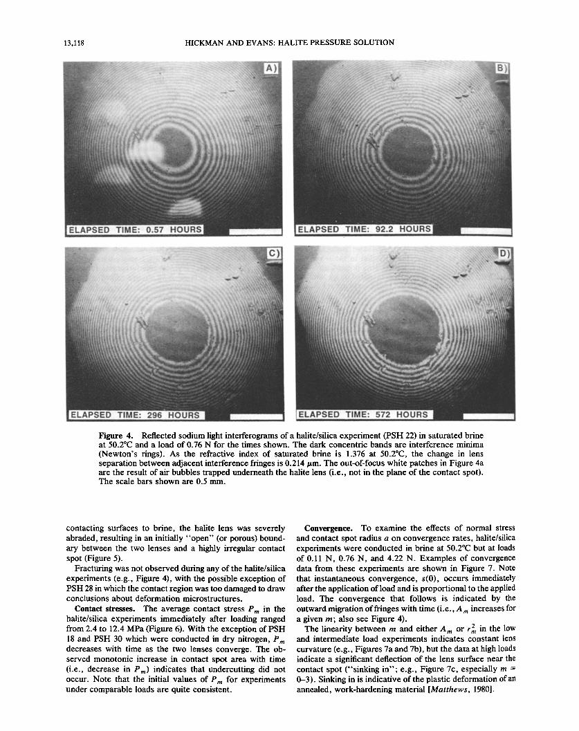
Contact morphologies. Typical interferograms for a ha- lite/silica experiment in brine at 50.2øC are shown in Figure 4. Notice that the contact spot (central dark region) remains roughly circular and does not develop the dendritic patterns that epitomize halite/halite experiments [Hickman and Evans, 1991, 1992].
Examinaction of the two samples fabricated dry at 90øC (laSH 28 and PSH 29) immediately after brine was injected into the sample chamber revealed that no air was trapped at the contact in either experiment. To ensure wetting of the contact in experiment PSH 28, the halite lens was rocked back and forth using a thin wire inserted into the sample chamber. Although this operation succeeded in exposing the
Table 1. Pressure Solution Experiments
Radius of Experiment How Temperature, Curvature, a Load, Duration, Convergence
Experiment øC cm Fluid N Fabricationb hours Measurede
Halite/Silica Experiments PSH 17 50.19 -- 0.20 9.29 brine 4.22 + 0.11 wet 290.3 a PSH 18 50.19 __ 0.05 9.16 nitrogen 4.21 -+ 0.11 -" 236.1 a PSH 22 50.20 -- 0.09 8.79 brine 0.762 -+ 0.023 wet 572.0 a PSH 23 50.21 -+ 0.07 7.10 brine 0.111 +- 0.004 wet 527.9 a PSH 26 50.23 +- 0.08 8.58 brine 0.763 +- 0.023 wet 572.6 ...d PSH 28 90.05 +-- 0.19 7.82 brine 0.111 -+ 0.005 dry e 179.2 a PSH 29 90.16 __ 0.17 7.17 brine 0.111 + 0.005 dry 336.8 a PSH 30 90.45 +_ 0.21 7.95 nitrogen 0.113 -+ 0.005 '.- 334.1 a PSH 3! 8.29 +- 0.16 f 8.18 brine 0.114 + 0.005 wet 500.4 a PSH 34 g 23 -+ 2 7.95 . air 4.23 +- 0.11 '" 187.6 r PSH 34 g 50.18 -- 0.04 7.95 air 4.16 - 0.11 '.- 286.0 r PSH 34 g 89.93 --- 0.15 7.95 air 4.07 +- 0.11 '" 102.7 r PSH 35 20 +- 1 8.0--9.1 air 0.098--10.79 .........
Halite/Montmorillonite/Silica Experiment PSH 27 50.22 +_ 0.08 8.18 brine 0.761 +-- 0.023 dry 359.0 r
aFor the plano-convex (halite) lens. bDry, lid to microscope stage closed before brine injected using brine inlet tubes; wet, brine added directly to contact before sample
assembled and microscope stage lid closed. Or, ray method; a, area method. aimperfection in lens adjacent to contact spot prevented accurate determination of convergence. eFabricated dry and then teased with wire inserted through upper brine inlet tube to wet contact. fExcept for power failure that occurred 95 hours into experiment, during which time the stage (thermistor) temperature increased steadily
to 13.4øC in 50 min before returning to run temperature. gReused halite lens from experiment PSH 30 (radius of curvature given is from experiment PSH 30).
13 118 HICKMAN AND EVANS: HALITE PRESSURE SOLUTION
A) B)
ELAPSED TIME' 0.57 HOURS
c)
ELAPSED TIME' 92.2 HOURS
D)
ELAPSED TIME: 296 HOURS ELAPSED TIME' 572 HOURS
Figure 4. Reflected sodium light interferograms of a halite/silica experiment (PSH 22) in saturated brine at 50.2øC and a load of 0.76 N for the times shown. The dark concentric bands are interference minima
(Newton's rings). As the refractive index of saturated brine is 1.376 at 50.2øC, the change in lens separation between adjacent interference fringes is 0.214/am. The out-of-focus white patches in Figure 4a are the result of air bubbles trapped underneath the halite lens (i.e., not in the plane of the contact spot). The scale bars shown are 0.5 mm.
contacting surfaces to brine, the halite lens was severely abraded, resulting in an initially "open" (or porous) bound- ary between the two lenses and a highly irregular contact spot (Figure 5).
Fracturing was not observed during any of the halite/silica experiments (e.g., Figure 4), with the possible exception of PSH 28 in which the contact region was too damaged to draw conclusions about deformation microstructures.
Contact stresses. The average contact stress Pm in the halite/silica experiments immediately after loading ranged from 2.4 to 12.4 MPa (Figure 6). With the exception of PSH 18 and PSH 30 which were conducted in dry nitrogen, Pm decreases with time as the two lenses converge. The ob- served monotonic increase in contact spot area with time (i.e., decrease in P,,,) indicates that undercutting did not occur. Note that the initial values of Pm for experiments under comparable loads are quite consistent.
Convergence. To examine the effects of normal stress and contact spot radius a on convergence rates, halite/silica experiments were conducted in brine at 50.2øC but at loads of 0.11 N, 0.76 N, and 4.22 N. Examples of convergence data from these experiments are shown in Figure 7. Note that instantaneous convergence, s(0), occurs immediately after the application of load and is proportional to the applied load. The convergence that follows is indicated by the outward migration of fringes with time (i.e., A rn increases for a given m; also see Figure 4).
The linearity between m and either A m or r7,, in the low and intermediate load experiments indicates constant lens curvature (e.g., Figures 7a and 7b), but the data at high loads indicate a significant deflection of the lens surface near the contact spot ("sinking in"; e.g., Figure 7c, especially m = 0-3). Sinking in is indicative of the plastic deformation of an annealed, work-hardening material [Matthews, 1980].

HICKMAN AND EVANS: HALITE PRESSURE SOLUTION 13,119
By subtracting the initial elastic/plastic deformation, s(0). from the total convergence, one obtains the time-dependent component of the convergence (henceforth simply called convergence' Figure 8). In PSH 22 and PSH 23, convergence x•as determined as the mean and standard deviation of using interference minima of orders 1-10. In PSH 17 and PSH 18 because of the sinking in near the contact conver- gence was determined using only orders 6-10 and 3-20, respectively. Note that the convergence rates are lowest for the experiment conducted at the highest load (PSH 17) and decrease with time. As explained below, this is a conse-
quence of the competing effects of normal stress and contact spot radius on convergence rates. No convergence was observed in the control experiment conducted at high load in dry nitrogen.
Experiments PSH 22 and PSH 26 were conducted in brine under the same conditions of temperature (50.2øC) and load
ELAPSED TIMœ: 1.08 HOURS.•
E•PSED•!ME: 179 HOURS
Figure 5. Reflected sodium interferograms of a halite/silica experiment (PSH 28) in saturated brine at 90. IøC and 0.11 N for the times shown. This sample was fabricated dry and then teased with a thin wire inserted through the upper brine inlet port after the addition of brine to ensure wetting of the contact spot. (a) Note the extensive damage done to the halite lens during this operation, especially above and to the right of the contact spot, and the presence of numerous fine scratches and open areas within the central contact. (b) After 179 hours, the halite lens is now in more intimate contact with the silica flat, although the contact spot is still highly irregular. The change in lens separation between adjacent interference fringes is 0.215/am. The scale bars are 0.5 mm.
14
HALITE/SILICA: A) 4.21 N 1--. PSH 17 ß -- ø PSH 18
• '-- ' PSH 22
• "-- •' PSH 26 • '---"--• 4.22 N
0.76 N
o :60 460 s60 ELAPSED TIME, HOURS
4 - ß
HALITE/SILICA (0.11 N): E• '--ø PSH 23 *--* PSH 28
> T '--" PSH 29 • '*- --t '--' PSH 30 •\ ' "--" PSH 31
2 '• HALITE/CLAY/SILICA:
• o--o PSH 27
O o 460
LAPSO HOURS
600
Figure 6. Mean effective normal stress Pm as a function of time for experiments in which a halite lens and silica lens were pressed together (halite/silica) at (a) high to intermedi- ate loads and (b) low loads. Also shown in Figure 6b are contact stresses for an experiment in which a halite convex lens was pressed against a fused silica disk coated with an approximately 0.8-/am-thick montmorillonite layer (halite/ clay/silica). With the exception of the halite/silica experi- ments in Figure 6b, which were loaded at about 0.11 N (Table 1), the applied loads are indicated for each experi- ment. Error bars are shown for all data from PSH 22 and
PSH 26 to facilitate comparison of data from these experi- ments conducted under similar conditions (Table 1). Error bars are shown for the last data points in the other experi- ments, but only when the error is larger than the correspond- ing symbol.
(0.76 N) to check repeatability. In experiment PSH 26 an imperfection in the surface of the halite lens near the contact spot prevented an accurate determination of convergence. Nevertheless, the convergence rates from these two exper- iments, as estimated from changes in contact spot area (or, equivalently, mean normal stress) with time using equation (3) for m = 0, are identical to within experimental error (Figure 6a).
To ascertain the effect of temperature on convergence rates, halite/silica experiments were also done at constant load (0.11 N) and at 8.3 ø, 50.2 ø and 90.2øC (Figure 9). A control experiment conducted in dry nitrogen at 0.11 N and 90.5øC indicated negligible dislocation creep. Experiments PSH 23, PSH 29, and PSH 31 show nearly identical conver- gence rates, even though the temperatures differed by 82øC. Note that the rate from PSH 28, whose contact spot was

13,120 HICKMAN AND EVANS: HALITE PRESSURE SOLUTION
• 11 0.76 NEWTONS, 50.2 ø C • 11 0.11 NEWTONS, 50.2 ø C A)
• ONVERGENCE
• 2 /•• ß 275.9 • 2 /'/•••• ' 296.2 • o 395.9 • , ••• o 428.2
o'.a' 1:o 1:: 1:o 1:: ENCLOSED AR•, mm 2 ENCLOSED AREA, mm 2
12 . t so. c c) g • lO
• 8 • • ,/• ////•CONVEREENOE • 7 • •CONVERGENCE • • BEFORE LOAD • • 6 BEFORE LOAD • • •• - • • 8 •• •_•••• TIME, HOURS: • 5 • • TIME, HOURS: • -
/' • ß 129.4 O
• 1 z • 290.8 0 0 ' 0.0 0.2 0.4 0.6 0.8 1.0 1.2 1.4 1.6 1.8 2.0 0.0 0.1 0.2 0.3 0.4 0.5 0.6 0.7 0.8 0.9 1.0
ENCLOSED AR•, mm 2 RADIUS SQUARED, mm 2 Figure 7. Examples of the plots used to measure convergence in the halite/silica experiments in brine: (a) PSH 23, (b) PSH 22, and (c) PSH 17. Also shown is the plot used to measure convergence in the halite/clay/silica experiment: (d) PSH 27. The dashed lines indicate the expected relationships between interference miralma order number m and either the enclosed area Am or the square of the radius of that minima r2m before the load is applied. The convergence that occurs immediately after the load is applied is indicated by s(0) and is followed by time-dependent convergence. The solid lines shown are linear regressions to the data for m = 1-10 (Figures 7a and 7b); rn = 6-10 (Figure 7c); and m = 5-14 (Figure 7d).
damaged by the in situ teasing operation, is comparable to that from PSH 29 also conducted at 90øC after the initial
period during which scratches and fluid-filled irregularities within the contact disappeared (Figure 5a). The initially rapid convergence in PSH 28 might be due to short-circuit diffusion through these fluid-filled irregularities.
Plastic deformation and the rebinder effect. Through a variety of processes collectively termed the Rebinder effect, water adsorbed onto the surfaces of ionic and covalent solids
can give rise to dislocation-controlled indentation creep [Latanision, 1977]. To see if the Rebinder effect contributed to convergence in our experiments, we conducted an addi- tional control experiment in air at high humidity and loads of 4.07-4.23 N. The lenses for this experiment (PSH 34) were exposed to laboratory air at 41% relative humidity for 27 hours and then sealed in this air in the microscope stage at room temperature. After 188 hours at approximately 23øC the temperature was increased to 50.2øC for 286 hours and then to 89.9øC for 103 hours, without disturbing the sample. Although an instantaneous convergence accompanied each increase in temperature, no time-dependent convergence was observed (Figure 10), suggesting that the Rebinder effect was not a significant factor in our experiments.
At the conclusion of PSH 34 the lid to the microscope
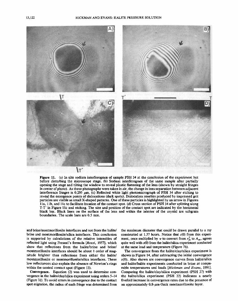
stage was loosened and tilted, revealing a residual flat spot on the halite lens, with the same size and at the same location as the contact spot (Figures 11a and 11b). The dislocation distribution was then determined by etching for about 1 rain in a solution of 4-g FeCI3 per liter of glacial acetic acid, followed by an acetone rinse [Mendelson, 1961] (Figure 11 c). The lens was then split through the contact spot along {001} and etched again. The second etching (Figure 1 ld) revealed very high dislocation densities in a region beneath and surrounding the contact spot. Bands of surface damage else- where on the lens surface (Figure 1 l c) resulted from reposi- tioning of the halite lens at the beginning of the experiment.
Phistic deformation in our experiments extended to depths of the order of several hundred microns (Figure 1 ld). Thus the lack of a significant Rebinder effect in the present study is not surprising, as this effect has been previously observed in indentation experiments only when the plastically deformed zone is confined to depths less than about 3 /am [Westbrook and Jorgensen, 1965; Ha.nnernan and Westbrook, 1968].
I-lalite/Siliea Experiment Using the Modified Tukon Tester
In experiment PSH 35, Pea across halite/silica contacts in air was measured as a function of load using the modified Tukon Tester (Figure 12), proceeding from the lowest load
HICKMAN AND EVANS: HALITE PRESSURE SOLUTION 13,121
0.5
HALITE/SlECA (50.2øC): 0.76 N (BRINE): =-- = PSH 17 Pmo= 7.6 MPa
0.4 ---- PSH 18 ao = 179/•mj•_ * --.-!S.H, • •• 0.11 N (BRINE):
0.3 • •om zo •• P mo = 2.4 aPa • ao = 122 •m
0.2 • 4.22 N (BRINE): • • P mo = 11.9 MPa
ao = 336 •m
• , -- .-, 4.21 N (DRY) 0.0 • .- .
-0.1
E•PSED TIME, HOURS
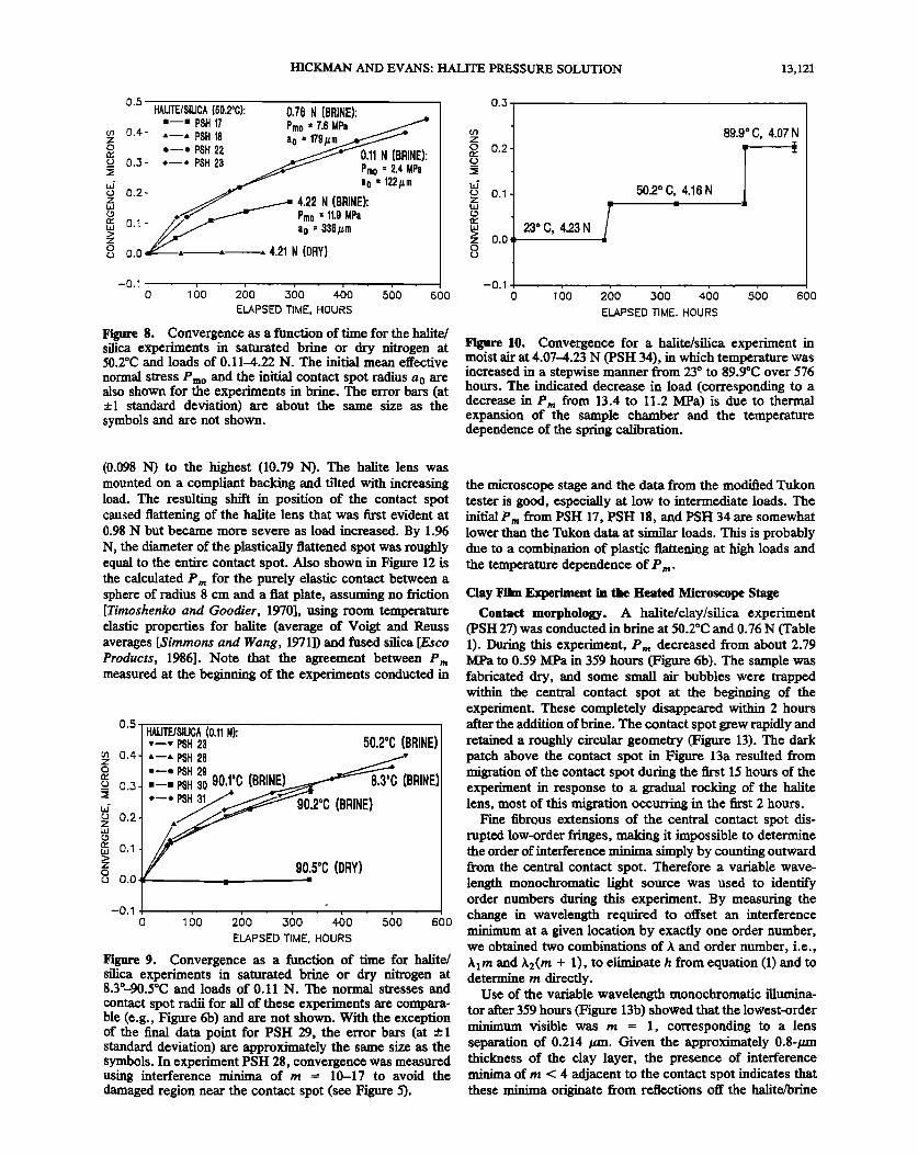
H•e 8. CO•CrSC•CC as a fo•cdo• of d•c fo• the •itc/ sgJ• cx•cd•c•ts in satired bd•c o• d• ni•osc• at 50.2øC •d loads of 0.11•.22 •. •bc i•ti• •e• c•octi•c
•o• stress •o •d the initi• co•tact spot sbo• fo• •c experiments in b•c. Tbc c•o• b•s (at s•d•d dc•iado•) •c about the s•c size • tbc
symbols and •c •ot sbo•.
0.3
z
-0.1
23 oC, 4.23N i
50.2 o C, 4.16 N
89.9 ø C, 4.07 N -
o ' ø ..... :z6o ' =6o ' .,,6o ' 56o ELAPSED TIME. HOURS
Figure 10. Convergence for a halite/silica experiment in moist air at 4.07-4.23 N (PSH 34), in which temperature was increased in a stepwise manner from 23 ø to 89.9øC over 576 hours. The indicated decrease in load (corresponding to a decrease in Pm from 13.4 to 11.2 MPa) is due to thermal expansion of the sample chamber and the temperature dependence of the spring calibration.
(0.098 N) to the highest (10.79 N). The halite lens was mounted on a compliant backing and tilted with increasing load. The resulting shift in position of the contact spot caused flattening of the halite lens that was first evident at 0.98 N but became more severe as load increased. By 1.96 N, the diameter of the plastically flattened spot was roughly equal to the entire contact spot. Also shown in Figure 12 is the calculated P m for the purely elastic contact between a sphere of radius 8 cm and a flat plate, assuming no friction [Timoshenko and Goodier, 1970], using room temperature elastic properties for halite (average of Voigt and Reuss averages [Simmons and Wang, 1971]) and fused silica [Esco Products, 1986]. Note that the agreement between Pm measured at the beginning of the experiments conducted in
0.5 -
0.4
0.3
0.2
0.•
0.0
-0.1
HALITE/SILICA (0.11 N): ß --- PSH 23 50.2øC (BRINE) •'--* PSH 28 "--' PSH 29 o ---PSH 30 90,1 C (BRINE)• (BRINE) ß --. PSH 3•• 90.200 (BRINE)
90_,5øC (DRY)
o '6o 260 4.60 560 600 ELAPSED TIME, HOURS
Figure 9. Convergence as a function of time for halite/ silica experiments in saturated brine or dry nitrogen at 8.3ø-90.5øC and loads of 0.11 N. The normal stresses and
contact spot radii for all of these experiments are compara- ble (e.g., Figure 6b) and are not shown. With the exception of the final data point for PSH 29, the error bars (at +-1 standard deviation) are approximately the same size as the symbols. In experiment PSH 28, convergence was measured using interference minima of m = 10-17 to avoid the damaged region near the contact spot (see Figure 5),
the microscope stage and the data from the modified Tukon tester is good, especially at low to intermediate loads. The initial Pm from PSH 17, PSH 18, and PSH 34 are somewhat lower than the Tukon data at similar loads. This is probably due to a combination of plastic flattening at high loads and the temperature dependence of P m.
Clay Film Experiment in the Heated Microscope Stage
Contact morphology. A halite/clay/silica experiment (PSH 27) was conducted in brine at 50.2øC and 0.76 N (Table 1). During this experiment, P m decreased from about 2.79 MPa to 0.59 MPa in 359 hours (Figure 6b). The sample was fabricated dry, and some small air bubbles were trapped within the central contact spot at the beginning of the experiment. These completely disappeared within 2 hours after the addition of brine. The contact spot grew rapidly and retained a roughly circular geometry (Figure 13). The dark patch above the contact spot in Figure 13a resulted from migration of the contact spot during the first 15 hours of the experiment in response to a gradual rocking of the halite lens, most of this migration occurring in the first 2 hours.
Fine fibrous extensions of the central contact spot dis- rupted low-order fringes, making it impossible to determine the order of interference minima simply by counting outward from the central contact spot. Therefore a variable wave- length monochromatic light source was used to identify order numbers during this experiment. By measuring the change in wavelength required to offset an interference minimum at a given location by exactly one order number, we obtained two combinations of X and order number, i.e., Aim and A2(m + 1), to eliminate h from equation (1) and to determine m directly.
Use of the variable wavelength monochromatic illumina- tor after 359 hours (Figure 13b) showed that the lowest-order minimum visible was m = 1, corresponding to a lens separation of 0.214 /zm. Given the approximately 0.8-/zm thickness of the clay layer, the presence of interference minima of m < 4 adjacent to the contact spot indicates that these minima originate from reflections off the halite/brine
13,122 HICKMAN AND EVANS: HALITE PRESSURE SOLUTION
i/"
A) 8)
Figure 11. (a) In situ sodium interferogram of sample PSH 34 at the conclusion of the experiment but before disturbing the microscope stage. (b) Sodium interferogram of the same sample after partially opening the stage and tilting the window to reveal plastic flattening of the lens (shown by straight fringes in center of photo). As these photographs were taken in air, the change in lens separation between adjacent interference fringes is 0.295 tzm. (c) Reflected white light photomicrograph of PSH 34 after etching to reveal the emergence points of dislocations (dark spots). Dislocation rosettes produced by impressed grit particles are visible as small X-shaped patterns. One of these particles is highlighted by an arrow in Figures 1 la, 1 lb, and 1 lc to facilitate location of the contact spot. (d) Cross section of PSH 34 after splitting along T-T' in Figure 1 lc and etching. The size and position of the contact spot are indicated by the horizontal black bar. Black lines on the surface of the lens and within the interior of the crystal are subgrain boundaries. The scale bars are 0.5 mm.
and brine/montmorillonite interfaces and not from the halite/ brine and montmorillonite/silica interfaces. This conclusion
is supported by calculations of the relative intensities of reflected light using Fresnel's formula [Rossi, 1957], which show that reflections from the halite/brine and brine/
montmorillonite interfaces should be about I order of mag- nitude brighter than reflections from either the halite/ montmorillonite or montmorillonite/silica interfaces. These
low reflectances also explain the absence of Newton's rings within the central contact spot (Figure 13).
Convergence. Equation (2) was used to determine con- vergence in the h•te/clay/silica experiment using orders 5-14 (Figure 7d). To avoid errors in convergence due to the contact spot migration, the radius of each fringe was determined from
the maximum diameter that could be drawn parallel to a ray constructed at 1.57 hours. Notice that s(0) from this experi- ment, once multiplied by rr to convert from r,• to A,,,, agrees quite well with s(0) from the halite/silica experiment conducted at the same load and temperature (Figure 7b).
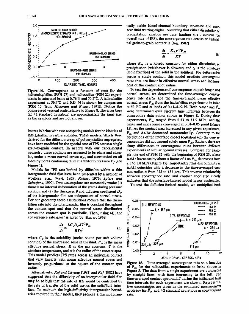
The convergence from the halite/clay/silica experiment is shown in Figure 14, after subtracting the initial convergence s(0). Also shown are convergence curves from halite/silica and halite/halite experiments conducted in brine at compa- rable temperatures and loads [Htckman and Evans, 1991]. Comparing the halite/clay/silica experiment (PSH 27) with the halite/silica experiment (PSH 22) indicates a nearly fivefold increase in convergence rates due to the presence of an approximately 0.8-/xm-thick montmorillonite layer.

HICKMAN AND EVANS: HALITE PRESSURE SOLUTION 13,123
Discussion Mechanics of Initial Elastic-Plastic Contact
E,•en at the lowest loads (•0.1 N), Pm is less than that calculated for purely elastic contact (Figure 12) [Johnson, 1987], suggesting that the initial deformation of the contact region included some plastic yielding in all the experiments. When a rigid sphere indents an elastic-plastic half-space, plastic slip initiates at a depth beneath the contact about equal to the contact spot radius at Pm • 1.1 Ys [Johnson, 1987], where Ys is the single-crystal yield stress for loading along (001). For the halite used in these experiments, Ys ranges from 0.6 to 3.0 MPa [Davidge and Pratt, 1964; Davis and Gordon, 1968; Carter and Heard, 1970]. With increasing load the plastic zone under the indentor expands until it breaks out to the free surface. In an annealed, work- hardening matehal (such as the halite used here), P m will then increase slowly with increasing load after this fully plastic mode of deformation is reached.
At a load of about 2 N the plastically flattened spot in PSH 35 was observed to be about the same size as the contact
spot. This plastic flattening, the slow increase in Pm with load above about 3 N (Figure 12), and the high dislocation densities observed in PSH 34 at 4.2 N (Figure 11) indicate that fully plastic deformation was achieved at loads greater than 2-4 N.
Kinetics of Pressure Solution: Normal Stress
and Path Length Dependence
Pressure solution is driven by gradients in the chemical potential induced by nonhydrostatic stresses. The thermo- dynamic formulation of this problem has often been debated [e.g., de Boer, 1977; Robin, 1978; Lehner, 1990]. Paterson [1973] and others have used the concept of local equilibrium
20
•_ AS C
•15 ß
• •0
• 1Ys o
[] ß
ONSET OF PLASTIC FLATTENING HALITE/SILICA SAMPLES: ß PSH 35 (TUKON TESTER) o PSH17 n PSH29 ß PSH18 o PSH30 ß PSH22 v PSH31 ,', PSH23 ß PSH34 v PSH 26
} • 61'01'1 LOAD, NEWTONS
Figure 12. Mean effective normal stress P m versus load from PSH 35 using the modified Tukon Hardness Tester shown in Figure 3. These measurements were made at 20øC and 50% relative humidity. The calculated variation of P m with load for the purely elastic contact of halite and silica lenses for the geometry used in this study is shown for comparison. Also shown are the initial Pm from the halite/ silica experiments conducted in the heated microscope stage; only Pm at 50.2øC is plotted for PSH 34 to facilitate comparison with other experiments at the same load and temperature. The range of P m over which plastic flow is predicted to initiate within the hahte lens below the contact.
spot is shown as 1.1 Y., (see text).
,,
' '• '•N.'•" ,•.
ELAPSED TIME: 359 HOURS
Figure 13. Reflected sodium interferograms of experiment PSH 27 in saturated brine at 50.2øC and 0.76 N for the times
shown. In this experiment a halite convex lens was pressed against a fused silica flat coated with an approximately 0.8-/xm-thick layer of sodium montmorillonite to ascertain the effect of a clay interlayer on convergence rates. The change in lens separation between adjacent interference fringes is 0.214/xm. The scale bars are 0.5 mm.
within a grain or interphase boundary to derive an expres- sion for the change in chemical potential owing to deviatoric stres se s:
(o' N - Pf) V (4)
where 5/x is the work done in transferring one mole of atoms from a grain or interphase boundary under a normal stress rr N to the wall of the open pore under a fluid pressure Pf and V is the molar volume of the solid. Chemical potential gradients arising from changes in elastic and/or plastic inter- nal strain energy or molar volume are assumed to be relatively small under most geologic conditions, in agree- ment with theoretical calculations [de Boer, 1977; Tada et al., 1987].
Intergranular pressure solution via water film diffusion requires the operation of three sequential processes: disso- lution into a grain or interphase bo,•ndary film under high normal stress, diffusion through that film, and precipitation at interfaces under low normal stress. The slowest of these
three steps will determine the overall deformation rate. Below, we compare the results from our halite/silica exper-
13,124 HICKMAN AND EVANS' HALITE PRESSURE SOLUTION
2.0
HAUTE-ON- SILICA (BRINE)
03 MONTMORILLONITE INTERLAYER (0.8 t z 1.5 0.76 NEWTONS 0
::2 1.0 Z HALITE-ON-SILICA (BRINE) o 0,5 0.76 NEWTONS
z o 0.0 ,
o HALITE-ON-HALITE (BRINE) 0.84 NEWTONS
-0.5 o •6o 260 36o 460
ELAPSED TIME, HOURS
Figure 14. Convergence as a function of time for the halite/clay/silica (PSH 27) and halite/silica (PSH 22) experi- ments in saturated brine at 0.76 N and 50.2øC. A halite/halite
experiment at 50.1øC and 0.84 N is shown for comparison (PSH 15 [from Hickman and Evans, 199!]). Notice the compressed vertical scale relative to Figure 8. The error bars (at -+ 1 standard deviation) are approximately the same size as the symbols and are not shown.
iments in brine with two competing models for the kinetics of intergranular pressure solution. These models, which were derived for the diffusion creep of polycrystalline aggregates, have been modified for the special case of IPS across a single grain-to-grain contact. In accord with our experimental geometry these contacts are assumed to be plane and circu- lar, under a mean normal stress (rN, and surrounded on all sides by pores containing fluid at a uniform pressure Pf (see Figure !).
Models for IPS rate-limited by diffusion within a thin intergranular fluid film have been presented by a number of workers [e.g., Weyl, 1959; Rutter, 1976; Spiers and Schutjens, 1990]. Two assumptions are commonly made: (1) there is no internal deformation of the grains during pressure solution and (2) the thickness/5 and diffusion coefficient D b of the intergranular film are independent of normal stress. For our geometry these assumptions require that the disso- lution rate into the intergranular film is constant throughout the contact spot and that the normal stress distribution across the contact spot is parabolic. Then, using (4), the convergence rate ds/dr is given'by [Rutter, 1976]
ds 8CoDb• V2Prn d-• = RTa 2 (5)
where Co is the solubility (moles solute per unit volume solution) of the unstressed solid in the fluid, P m is the mean effective normal stress, R is the gas constant, T is the absolute temperature, and a is the radius of the contact spot. This model predicts IPS rates across an individual contact that vary linearly with mean effective normal stress and inversely proportional to the square of the contact spot radius.
Alternatively, Raj and Chyung [19811 and Raj [1982] have suggested that the diffusivity of an intergranular fluid film may be so high that the rate of IPS would be controlled by the rate of transfer of the solid across the solid/fluid inter-
face. To maintain the high-diffusivity intergranular bound- aries required in their model, they propose a thermodynam-
ically stable island-channel boundary stn•cture and near. zero fluid wetting angles. Assuming that either dissolution or precipitation kinetics are rate limiting (i.e., control the overall rate of !PS), the convergence rate across an individ- ual grain-to-grain contact is [Raj, 1982]
ds K+X VPm dt RT (6)
where K+ is a kinetic constant for either dissolution or precipitation (whichever is slowest) and X is the solubility (mole fraction) of the solid in the solution. For deformation across a single contact, this model predicts convergence rates that are linear in effective normal stress and indepen- dent of the contact spot radius.
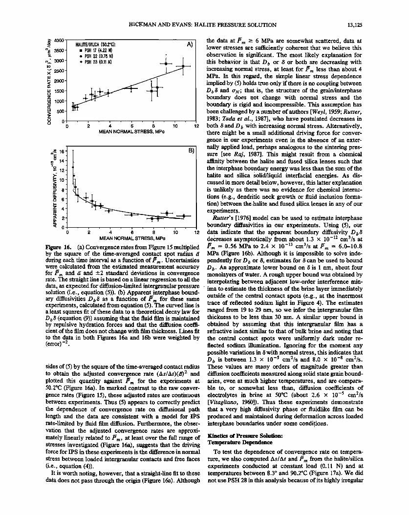
To test the dependence of convergence on path length and normal stress, we determined the time-averaged conver. gence rate As/At and the time-averaged mean effective normal stress Pm from the halite/silica experiments in brine at 50.2øC and at loads of 0.11-4.22 N. Both As/At and •m were determined over discrete time intervals between the consecutive data points shown in Figure 8. During these experiments, P rn ranged from 0.53 to 11.9 MPa, and the halite and silica lenses converged at 0.01-0.05/zm/d (Figure 15). As the contact area increased in any given experiment, P m and As/At decreased monotonically. Contrary to the predictions of the interface model (equation (6)) the conver- gence rates did not depend solely upon/•rn. Rather, there are sharp differences in convergence rates between different experiments at similar normal stresses. Compare, for exam- ple, the end of PSH 22 with the beginning of PSH 23, where As/At increases by about a factor of 4 as •m decreases from 2.3 to 1.8 MPa (Figure 15). Importantly, this discontinuity in As/At coincides with a decrease in the time-averaged con- tact radius t• from 325 to 152/zm. This inverse relationship between convergence rate and contact spot size clearly indicates that the interface-limited model is not applicable.
To test the diffusion-limited model, we multiplied both
0.06
0.05
0.04-
0.03
0.02
0.01
0.00
0,11 NEWTONS HALITE/SILICA (50.2øC}: "•" PSH 17
. • = 152/•m 0--0 PSH 22 0.76 NEWTONS 0--0 PSH 23
•• • = 210/•m
••1• TIME 4,22 NEWTONS • = 354/•m
,•«• 251•rn 325•rn 414/•m
0 ' ' ; ' ' ' MEAN NORMAL STRESS, MPo
Figu_re 15. Time-averaged convergence rate as a function of P rn for the halite/silica experiments in brine shown in Figure 8. The data from a single experiment are connected by straight lines, with time increasing to the left. The time-averaged contact spot radii t7 during the initial and final time intervals for each experiment are shown. Representa- tive uncertainties are given as the estimated measurement accuracy for P,• and _+2 standard deviations in convergence rate.
HICKMAN AND EVANS: HALITE PRESSURE SOLUTION 13,12J
4000-
3,500
2500
2000 1500
1000
500
o
A) HALITE/SILICA (50.2øC): m PSH 17 (4.22 N)
ß PSH 22 (0.76 N) • ß PSH 23 (0.11 N)
0 ' '• •t • • 1'0 12 MEAN NORMAL STRESS, MPo
• 14-
ß " 12
i..- lO
• 8
• 6-
z 4
( 2'
'< o o
MEAN NORMAL STRESS, MPo
B)
12
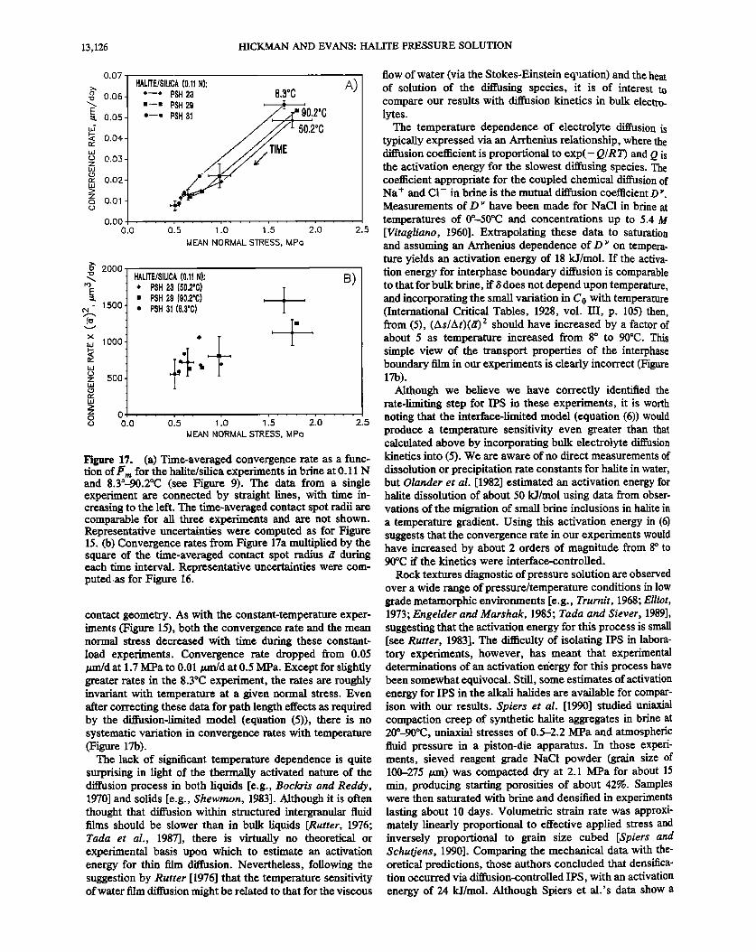
Figure 16. (a) Convergence rates from Figure 15 multiplied by the square of the time-averaged contact spot radius 5 during each time interval as a function of/•rn. Uncertainties were calculated from the estimated measurement accuracy for P m and a and +2 standard deviations in convergence
the data at/•m >- 6 MPa are somewhat scattered, data at lower stresses are sufficiently coherent that we believe this observation is significant. The most likely explanation for this behavior is that Do or /5 or both are decreasing with increasing normal stress, at least for J•m less than about 4 MPa. In this regard, the simple linear stress dependence implied by (5) holds true only if there is no coupling between D0/• and Cr•v; that is, the structure of the grain/interphase boundary does not change with normal stress and the boundary is rigid and incompressible. This assumption has been challenged by a number of authors [Weyl, 1959; Rutter, 1983; Tada et al., 1987], who have postulated decreases in both/• and D 0 with increasing normal stress. Alternatively, there might be a small additional driving force for conver- gence in our experiments even in the absence of an exter- nally applied load, perhaps analogous to the sintering pres- sure [see Raj, 1987]. This might result from a chemical affinity between the halite and fused silica lenses such that the interphase boundary energy was less than the sum of the halite and silica •olid/liquid interfacial energies. As dis- cussed in more detail below, however, this latter explanation is unlikely as there was no evidence for chemical interac- tions (e.g., dendritic neck growth or fluid inclusion forma- tion) between the halite and fused silica lenses in any of our experiments.
Rutter's [1976] model can be used to estimate interphase boundary diffusivities in our experiments. Using (5), our data indicate that the apparent boundax3r diffusivity D0/• decreases asymptotically from about 1.3 x 10-•2 cm3/s at P-m = 0.56 MPa to 2.4 x 10 -13 cm3/s at/•m = 6.0-10.8 MPa (Figure 16b). Although it is impossible to solve inde- pendently for D 0 or/•, estimates for 8 can be used to bound D 0. An approximate lower bound on/5 is 1 rim, about four monolayers of water. A rough upper bound was obtained by
rate. The straight line is based on a linear regression to all the interpolating between adjacent low-order interference min- data, as expected for diffusion-limited intergranular pressure . ima to estimate the thickness of the brine layer immediately solution (i.e., equation (5)). (b) Apparent interphase bound- ary diffusivities Do/• as a function of/•m for these same experiments, calculated from equation (5). The curved line is a least squares fit of these data to a theoretical decay law for D0/5 (equation (9)) assuming that the fluid film is maintained by repulsive hydration forces and that the diffusion coeffi- cient of the film does not change with film thickness. Lines fit to the data in both Figures 16a and 16b were weighted by (error) -2.
sides of (5) by the square of the time-averaged contact radius to obtain the adjusted convergence rate (As/At)(t7) 2 and plotted this quantity against Pm for the experiments at 50.2øC (Figure 16a). In marked contrast to the raw conver- gence rates (Figure 15), these adjusted rates are continuous between experiments. Thus (5) appears to correctly predict the dependence of convergence rate on diffusional path length and the data are consistent with a model for I•S rate-limited by fluid film diffusion. Furthermore, the obser- vation that the adjusted convergence rates are approxi- mately linearly related to l•m, at least over the full range of stresses investigated (Figure 16a), suggests that the driving force for IPS in these experiments is the difference in normal stress between loaded intergranular contacts and free faces (i.e., equation (4)).
It is worth noting, however, that a straight-line fit to these data does not pass through the origin (Figure 16a). Although
outside of the central contact spots (e.g., at the innermost trace of reflected sodium light in Figure 4). The estimates ranged from 19 to 29 rim, so we infer the intergranular film thickness to be less than 30 nm. A similar upper bound is obtained by assuming that this intergranular film has a refractive index similar to that of bulk brine and noting that the central contact spots were uniformly dark under re- flected sodium illumination. Ignoring for the moment any possible variations in/• with normal stress, this indicates that D o is between 1.3 x 10 -s cm2/s and 8.0 x 10 -8 cm2/s. These values are many orders of magnitude greater than diffusion coefficients measured along solid state grain bound- aries, even at much higher temperatures, and are compara- ble to, or somewhat less than, diffusion coefficients of electrolytes in brine at 50øC (about 2.6 x 10 -5 cm2/s [Vitagliano, 1960]). Thus these experiments demonstrate that a very high diffusivity phase or fluidlike film can be produced and maintained during deformation across loaded interphase boundaries under some conditions.
Kinetics of Pressure Solution:
Temperature Dependence
To test the dependence of convergence rate on tempera- ture, we also computed As/At and Pm from the halite/silica experiments conducted at constant load (0.11 N) and at temperatures between 8.3 ø and 90.2øC (Figure 17a). We did not use PSH •8 in this analysis because of its highly irregular
13,126 HICKMAN AND EVANS: HALITE PRESSURE SOLUTION
0.07
-o 0.06
E :• 0.05
• 0.04
r..a 0.03 z
n- 0.02
z o 0.01
HALITE/SILICA (0.11 N): *--o PSH 23 8,3øC "--' PSH29 *-----•--'--'•
50.2øC
A)
0.00 o.o .... .... .... ' 2:0
MEAN NORMAL STRESS, MPo
o 2000
- 1500
Io
x
,,, 1000
z 500
z o
HALITE/SILICA (0.11 N): * PSH 23 (50,2øC) ß PSH 29 (90.2ø0) ø PSH 31 (8.3øC)
'I
B)
o 0.0 .... 025' 1:0 1:5 2:"0 2.5
MEAN NORMAL STRESS, MPo
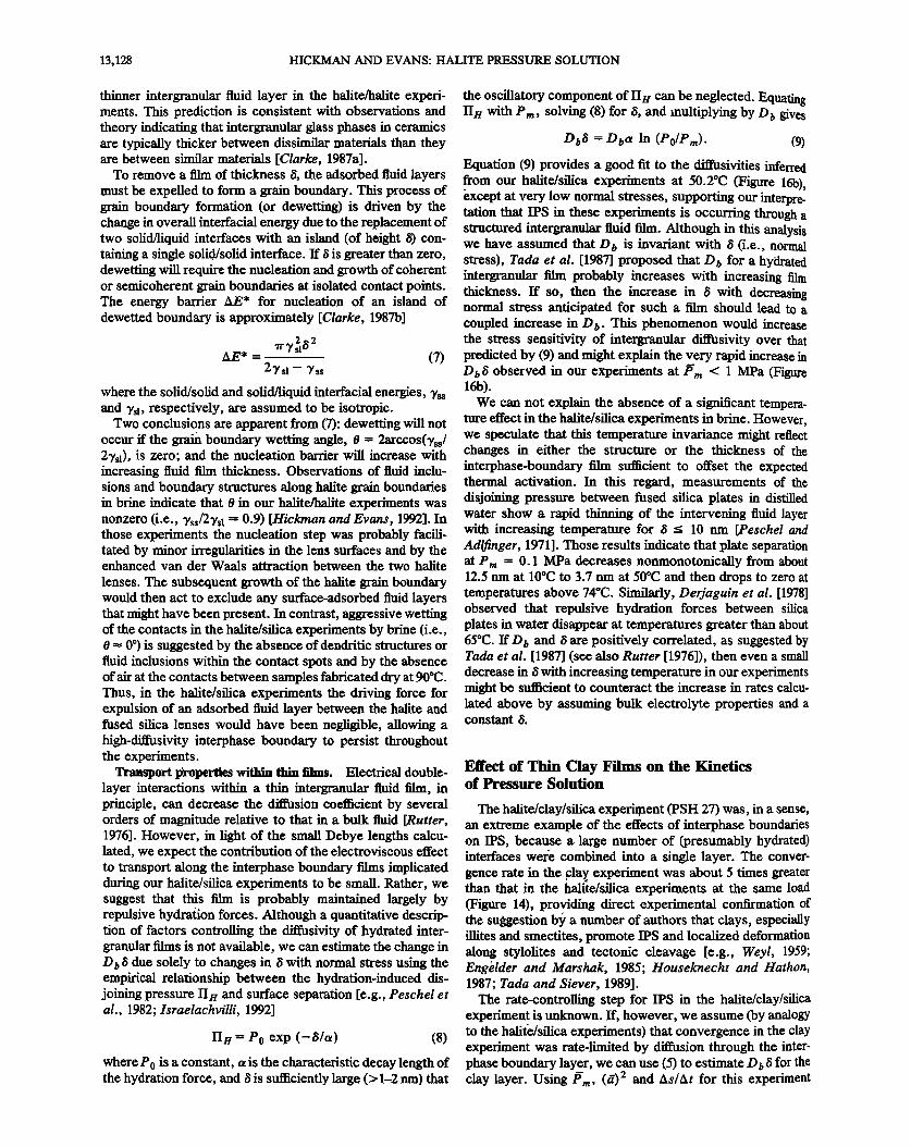
Figure 17. (a) Time-averaged convergence rate as a func- tion of/•m for the halite/silica experiments in brine at 0.11 N and 8.3ø-90.2øC (see Figure 9). The data from a single experiment are connected by straight lines, with time in- creasing to the left. The time-averaged contact spot radii are comparable for all three experiments and are not shown. Representative uncertainties were computed as for Figure 15. (b) Convergence rates from Figure 17a multiplied by the square of the time-averaged contact spot radius fi during each time interval. Representative uncertainties were com- puted.as for Figure 16.
contact geometry. As with the constant-temperature exper- iments (Figure 15), both the convergence rate and the mean normal stress decreased with time during these constant- load experiments. Convergence rate dropped from 0.05 /xm/d at 1.7 MPa to 0.01/•m/d at 0.5 MPa. Except for slightly greater rates in the 8.3øC experiment, the rates are roughly invariant with temperature at a given normal stress. Even after correcting these data for path length effects as required by the diffusion-limited model (equation (5)), there is no systematic variation in convergence rates with temperature (Figure 17b).
The lack of significant temperature dependence is quite surprising in light of the thermally activated nature of the diffusion process in both liquids [e.g., Bockris and Reddy, 1970] and solids [e.g., Shewrnon, 1983]. Although it is often thought that diffusion within structured intergranular fluid films should be slower than in bulk liquids [Rutter, 1976; Tada et at., 1987], there is virtually no theoretical or experimental basis upon which to estimate an activation energy for thin film diffusion. Nevertheless, following the suggestion by Rutter [1976] that the temperature sensitivity of water film diffusion might be related to that for the viscous
flow of water (via the Stokes-Einstein equation) and the heat of solution of the diffusing species, it is of interest to compare our results with diffusion kinetics in bulk electro- lytes.
The temperature dependence of electrolyte diffusion is typically expressed via an Arrhenius relationship, where the diffusion coefficient is proportional to exp(-Q/RT) and Q is the activation energy for the slowest diffusing species. The coefficient appropriate for the coupled chemical diffusion of Na + and C1- in brine is the mutual diffusion coefficient D •. Measurements of D • have been made for NaC! in brine at temperatures of 0ø-50øC and concentrations up to 5.4 M [Vitagliano, 1960]. Extrapolating these data to saturation and assuming an Arrhenius dependence of D • on tempera- ture yields an activation energy of 18 kJ/mol. If the activa- tion energy for interphase boundary diffusion is comparable to that for bulk brine, if/5 does not depend upon temperature, and incorporating the small variation in C0 with temperature (International Critical Tables, 1928, vol. III, p. 105)then, from (5), (As/At)(• 2 should have increased by a factor of about 5 as temperature increased from 8 ø to 90øC. This simple view of the transport properties of the interphase boundary film in our experiments is clearly incorrect (Figure 17b).
Although we believe we have correctly identified the rate-limiting step for IPS in these experiments, it is worth noting that the interface-limited model (equation (6)) would produce a temperature sensitivity even greater than that calculated above by incorporating bulk electrolyte diffusion kinetics into (5). We are aware of no direct measurements of dissolution or precipitation rate constants for halite in water, but Olander et al. [1982] estimated an activation energy for halite dissolution of about 50 kJ/mol using data from obser- vations of the migration of small brine inclusions in halite in a temperature gradient. Using this activation energy in (6) suggests that the convergence rate in our experiments would have increased by about 2 orders of magnitude from 8 ø to 90øC if the kinetics were interface-controlled.
Rock textures diagnostic of pressure solution are observed over a wide range of pressure/temperature conditions in low grade metamorphic environments [e.g., Trurnit, 1968; Elliot, 1973; Engelder and Marshak, 1985; Tada and Siever, 1989], suggesting that the activation energy for this process is small [see Rutter, 1983]. The difficulty of isolating IPS in labora- tory experiments, however, has meant that experimental determinations of an activation er/ergy for this process have been somewhat equivocal. Still, some estimates of activation energy for IPS in the alkali halides are available for compar- ison with our results. Spiers et at. [1990] studied uniaxial compaction creep of synthetic halite aggregates in brine at 20ø-90øC, uniaxial stresses of 0.5-2.2 MPa and atmospheric fluid pressure in a piston-die apparatus. In those experi- ments, sieved reagent grade NaC1 powder (grain size of 100-275 /xm) was compacted dry at 2.1 MPa for about 15 min, producing starting porosities of about 42%. Samples were then saturated with brine and densifted in experiments lasting about 10 days. Volumetric strain rate was approxi- mately linearly proportional to effective applied stress and inversely proportional to grain size cubed [Spiers and Schutjens, 1990]. Comparing the mechanical data with the- oretical predictions, those authors concluded that densifica- tion occurred via diffusion-controlled IPS, with an activation energy of 24 kJ/mol. Although Spiers et al.'s data show a

HICKMAN AND EVANS: HALITE PRESSURE SOLUTION 13,127
clear increase in compaction rate with increasing tempera- ture, it must be emphasized that their data are from monom- ineralic halite aggregates. Thus the relevance of the activa- tion energy determined in their experiments to water film diffusion at interphase boundaries, such as those studied in our halite/silica experiments, is unclear.
Pharr and Ashby [1983] reported an activation energy of 19 kJ/mol for water-enhanced creep of potassium chloride. However, given the high initial porosities in their samples and the accelerating tertiary creep rates observed in their uniaxial creep tests, it is difficult to rule out cataclasis as contributing to the enhanced creep rates. Even if IPS was rate limiting in their experiments, no microstructural obser- vations were made, nor was the grain size dependence of creep rate determined; thus one cannot use their data to differentiate between the diffusion-limited, interface-limited, and undercutting models.
Interphase Boundary Structure and Properties in the Halite/Silica Experiments
As there was no undercutting in our halite/silica experi- ments, they provide a direct demonstration of the water film diffusion mechanism for IPS. Importantly, there was also no evidence in our experiments, at least on an optical scale, for metastable island-channel structures as postulated by Raj [1982], Spiers and Schutjens [1990], and Lerner [1990]. Those workers theorized that island-channel structures
should form in response to highly localized gradients in the Helmholtz free energy (including contributions from elastic and plastic deformation) along grain/interphase boundaries. Although Spiers et aI. [1990] interpreted microstructural observations made after their halite compaction experiments as indicating the presence of a fine-scale island-channel network along the grain boundaries during deformation, they note that boundary structures could be modified during or after unloading. The absence of these structures in our experiments is especially significant because we were able to observe the halite/silica interphase boundaries directly while under load, and as shown above, the contact regions in our high-load halite/silica experiments initially deformed in a fully plastic manner, with very high dislocation densities in direct contact with the interphase boundary. Our halite/silica experiments thus suggest that the boundaries between dis- similar materials in aqueous fluids can contain structured fluid films with remarkable transport properties and that these pr.operties, in turn, may exert a profound influence on the kinetics of IPS. Below, we briefly discuss the nature and properties of thin fluid films along interphase boundaries.
Forces between surfaces. The forces acting between sur- faces contribute to such diverse processes as subcritical crack growth [Wiederhorn and Fuller, 1989], stability of colloids [Hiemenz, 1986], and diffusive mass transfer along grain boundaries [e.g., Clarke, 1987a; Heidug, 1995]. In addition to the strong chemical bonds that act at very small distances (less than atomic dimensions), the dominant forces acting between two surfaces in an aqueous solution are van der Waals forces; hydration, or solvation, forces; and forces arising from overlap of the diffuse portion of the electrical double layers associated with the adjacent surfaces [e.g., Adamson, 1982; Horn, 1990; Israelachvili, 1992]. The sum of these forces, called the disjoining pressure, will determine the thickness of a fluid film between two solids in equilibrium with an applied normal stress. Experimental observations
and theoretical estimates of the magnitude of the disjoining pressure vary widely and, for the silica-water system, range from a few megapascals up to about 270 MPa for a mono- layer of water (see discussion by Heidug [1995]). As our experiments were conducted in a concentrated electrolyte solution, the diffuse portion of the electrical double layer (the Gouy-Chapman layer) is expected to be extremely thin; the calculated Debye length is about 0.1 nm in saturated brine at 50øC. Thus disjoining forces due to double layer repulsion can probably be neglected.
In general, the largest of the van der Waals forces are dispersion forces, which arise through electromagnetic inter- actions between fluctuating dipoles in adjacent solids. Dis- persion forces between two plane-parallel surfaces decay as the inverse third power of plate separation. For two bodies of the same material separated by a liquid, the total van der Waals interaction is always attractive. Van der Waals inter- actions between dissimilar materials in a liquid, however, may be either attractive or repulsive depending upon the relative dielectric properties of the two solids and the intervening liquid. From the approximate solution derived by Israelachvili [1992, equation 11.13], we calculate that the van der Waals interaction should be attractive in all of our
experiments in brine but that it should be twice as strong between two halite lenses as between a halite and a silica lens.
Even when there is a strong van der Waals attraction between two surfaces, adhesive contact can be prevented by hydration forces. Although hydration forces are poorly understood, they are thought to result from the structuring and ultimate expulsion of hydrated ions and water molecules as two hydrophilic (water loving) surfaces are brought to- gether [Etzler and Drost-Hansen, 1983; Israelachvili, 1985; Horn, 1990]. Hydration forces have been measured between curved surfaces of mica [Pashley, 1981, 1985; Pashley and Israelachvili, 1984] and fused silica [Peschel and Adlfinger, 1969, 1971; Peschel et al., 1982; Horn et al., 1989] in pure water and in electrolyte solutions. These measurements show that hydration forces (1) are always repulsive; (2) dominate over other surface forces at separations, /5, less than about 5-10 nm; (3) increase exponentially with decreas- ing surface separation, with a superimposed oscillatory component for/5 < 1.5 nm; and (4) have characteristic decay lengths in electrolyte solutions that are relatively constant at 0.6-1.1 nm for concentrations greater than about 0.01 M. Unfortunately, we are aware of no measurements of disjoin- ing pressure for either the halite/silica or halite/halite sys- tems in saturated brine.
Conditions for the existence of thin fluid films. Consider-
ation of these surface forces in conjunction with strong (but short range) chemical bonds yields a simple qualitative explanation for the difference in behavior between the halite/halite experiments in brine, for which no convergence was observed [Hickman and Evans, 1991], and the halite/ silica experiments in brine, for which convergence was observed (this study). Two processes must occur in se- quence before two particles can be brought together to form a solid-state grain or interphase boundary [Clarke, 1987a]. The first, homogeneous thinning of the intervening fluid layer, is governed by the net disjoining pressure between the two phases. Although the relative magnitudes of the hydra- tion forces appropriate for these experiments are unknown, the van der Walls interaction alone would tend to promote a
13,128 HICKMAN AND EVANS: HALITE PRESSURE SOLUTION
thinner intergranular fluid layer in the halite/halite experi- ments. This prediction is consistent with observations and theory indicating that intergranular glass phases in ceramics are typically thicker between dissimilar materials than they are between similar materials [Clarke, 1987a].
To remove a film of thickness/3, the adsorbed fluid layers must be expelled to form a grain boundary. This process of grain boundary formation (or dewetting) is driven by the change in overall interfacial energy due to the replacement of two solid/liquid interfaces with an island (of height/3) con- taining a single solid/solid interface. If/3 is greater than zero, dewetting will require the nucleation and growth of coherent or semicoherent grain boundaries at isolated contact points. The energy barrier AE* for nucleation of an island of dewetted boundary is approximately [Clarke, 1987b]
w .y s2•/3 2 AE* = ' (7)
2Tsl- Tss
where the solid/solid and solid/liquid interfacial energies, •'ss and Ys•, respectively, are assumed to be isotropic.
Two conclusions are apparent from (7): dewetting will not occur ff the grain boundary wetting angle, 0 = 2arccos(%s/ 2Tsl), is zero; and the nucleation barrier will increase with increasing fluid film thickness. Observations of fluid inclu- sions and boundary structures along halite grain boundaries in brine indicate that 0 in our halite/halite experiments was nonzero (i.e., •,ss/2%1 • 0.9) [Hickman and Evans, 1992]. In those experiments the nucleation step was probably facili- tated by minor irregularities in the lens surfaces and by the enhanced van der Waals attraction between the two halite
lenses. The subsequent growth of the halite grain boundary would then act to exclude any surface-adsorbed fluid layers that might have been present. In contrast, aggressive wetting of the contacts in the halite/silica experiments by brine (i.e., 0 •- 0 ø) is suggested by the absence of dendritic structures or fluid inclusions within the contact spots and by the absence of air at the contacts between samples fabricated dry at 90øC. Thus, in the halite/silica experiments the driving force for expulsion of an adsorbed fluid layer between the halite and fused silica lenses would have been negligible, allowing a high-diffusivity interphase boundary to persist throughout the experiments.
Transport properties within thin films. Electrical double- layer interactions within a thin intergranular fluid film, in principle, can decrease the diffusion coefficient by several orders of magnitude relative to that in a bulk fluid [Rutter, 1976]. However, in light of the small Debye lengths calcu- lated, we expect the contribution of the electroviscous effect to transport along the interphase boundary films implicated during our halite/silica experiments to be small. Rather, we suggest that this film is probably maintained largely by repulsive hydra/ion forces. Although a quantitative descrip- tion of factors controlling the diffusivity of hydrated inter- granular films is not available, we can estimate the change in D0/3 due solely to changes in/3 with normal stress using the empirical relationship between the hydration-induced dis- joining pressure II• and surface separation [e.g., Peschel et al., 1982; Israelachvilli, 1992]
IIH = P0 exp (-/3/a) (8)
where P0 is a constant, •z is the characteristic decay length of the hydration force, and/3 is sufficiently large (> I-2 nm) that
the oscillatory component of iIn can be neglected. Equating II• with Pro, solving (8) for/3, and multiplying by D o gives
Do/3 = Dba In (Po/Pm). (9)
Equation (9) provides a good fit to the diffusivities inferred from our halite/silica experiments at 50.2øC (Figure 16b), •xcept at very low normal stresses, supporting our interpre- tation that IPS in these experiments is occurring through a structured intergranular fluid film. Although in this analysis we have assumed that Do is invariant with /3 (i.e., normal stress), Tada et al. [1987] proposed that Do for a hytlrated intergranular film probably increases with increasing film thickness. If so, then the increase in /3 with decreasing normal stress anticipated for such a film should lead to a coupled increase in D b. This phenomenon would increase the stress sensitivity of intergranular diffusivity over that predicted by (9) and might explain the very rapid increase in D o/3 observed in our experiments at/5 m < 1 MPa (Figure 16b).
We can not explain the absence of a significant tempera- ture effect in the halite/silica experiments in brine. However, we speculate that this temperature invariance might reflect changes in either the structure or the thickness of the interphase-boundary film sufficient to offset the expected thermal activation. In this regard, measurements of the disjoining pressure between fused silica plates in distilled water show a rapid thinning of the intervening fluid layer with increasing temperature for /3 _< 10 nm [Peschel and Adlfinger, 1971]. Those results indicate that plate separation at P m = 0.1 MPa decreases nonmonotonically from about 12.5 nm at 10øC to 3.7 nm at 50øC and then drops to zero at temperatures above 74øC. Similarly, Derjaguin et al. [1978] observed that repulsive hydration forces between silica plates in water disappear at temperatures greater than about 65øC. If D0 and/3 are positively correlated, as suggested by Tada et al. [1987] (see also Rutter [1976]), then even a small decrease in/3 with increasing temperature in our experiments might be sufficient to counteract the increase in rates calcu- lated above by assuming bulk electrolyte properties and a constant &
Effect of Thin Clay Films on the Kinetics of Pressure Solution
The halite/clay/silica experiment (PSH 27) was, in a sense, an extreme example of the effects of interphase boundaries on IPS, because a large number of (presumably hydrated) interfaces were combined into a single layer. The conver- gence rate in the cla• experiment was about 5 times greater than that in the halite/silica experiments at the same load (Figure 14), providing direct experimental confirmation of the suggestion b9 a number of authors that clays, especially illites and smectites, promote IPS and localized deformation along stylolites and tectonic cleavage [e.g., Weyl, 1959; Eng•Ider and Marshak, !985; Houseknecht and Hathon, 1987; Tada and Siever, 1989].
The rate-controlling step for IPS in the halite/clay/silica experiment is unknown. If, however, we assume (by analogy to the halite/silica experiments) that convergence in the clay experiment was rate-limited by diffusion through the inter- phase boundary layer, we can use (5) to estimate D0/3 for the clay layer. Using/•m, (5) 2 and As/At for this experiment
HICKMAN AND EVANS: HALITE PRESSURE SOLUTION 13,129
over elapsed times of 129-359 hours yields D0/t • 3.7 x 10 - • • cm3/s, about 30 times greater than the highest D 0/i estimated from the halite/silica experiments at 50øC. If/t • 0.8 tan for the montmorillonite layer, then the apparent (or bulk) diffusion coefficient for this layer is about 4.6 x 10 -7 cm2/s, about in the middle of the range of diffusion coeffi- cients estimated for our halite/silica experiments at the same temperature (1.3 x 10 -5 to 8.0 x 10 -8 cm2/s). If the diffusion-limited model is appropriate to this experiment, then it is clear that montmorillonite can maintain a high volume percentage of adsorbed (structured) water or inter- particle bulk water between grains even while under load. In fact, such an interpretation agrees with simultaneous mea- surements of swelling pressure and c axis spacing in a Na-montmorillonite immersed in a 10 -4 N NaC1 solution [Viani et al., 1983]. Under an applied normal stress of 0.8 MPa (comparable to P rn during our halite/clay/silica experi- ment) the thickness of the interlayer water in the Rio Escondido montmorillonite was found by these investigators to be about 3 times greater than that of the intervening silicate layers (i.e., a water/clay ratio of about 3/1).
The ability of montmorillonite to adsorb interlayer and surface water and swell even while under load made it an
attractive candidate for our experiment. For this reason we must consider the possibility that clay extruded from under the contact. We can rule this possibility out, however, because extrusion of clay would have caused the clay coating at the perimeter of the contact to warp or buckle. As described above, we used a monochrometer to verify that the Newton's tings arose from reflections from the upper surface of the clay layer and the lower surface of the halite lens. Thus any distortion or thickening within the clay layer adjacent to the contact spot would have been clearly visible as perturbations to the lower-order interference fringes. These perturbations were not observed (Figure 13).
Relevance to Fault-Zone Rheology
Even in the absence of pressure solution, gradients in surface curvature give rise to two other types of solution- transport processes: neck growth and crack healing. During crack healing, material diffuses from the fiat wall of a crack to the highly curved crack tip, resulting in infilling of the crack with the host material [e.g., Smith and Evans, 1984; Brantley et al., 1989]. During neck growth, material is dissolved along the wall of an open pore, diffuses through the pore fluid and precipitates at the sharply curved contacts between grains [Hickman and Evans, 1992].
Pressure solution, neck growth and crack healing can affect fault zone rheology in markedly different ways. Pres- sure solution can lead to time-dependent convergence or slip between grains or asperities in co/ttact, resulting in densift- cation and/or shear creep of a fault gouge or sediment. Neck growth, however, leads to an increase in the size of the contact between two grains or asperities, resulting in indu- ration and strengthening. Theoretical analysis has shown that pressure solution might result in aseismic creep along faults and a reduction in overall fault strength [Rutter and Mainprice, 1979]. Neck growth and crack healing, however, may lead to the time-dependent strengthening of faults between earthquakes [e.g., Fredrich and Evans, 1992; Hick- man and Evans, 1992] or allow the formation of pressure seals along faults which prevent the escape of overpressured pore fluids [e.g., Blanpied et al., 1992; Byerlee, 1993]. Which
of these processes dom/nates along any given fault will depend on a variety of factors, including temperature, stress, fluid chemistry, pore or crack geometry, grain size, and mineralogy.
Mineralogic observations on gouges from the San Andreas and other mature fault zones at shallow depths indicate that these gouges are mineralogically diverse; contain large per- centages of illites, smectites, and other clays; and are very fine-grained [e.g., Wu, 1978; Chester eta!., 1993]. In the experiments reported here, we observed no neck growth and a dramatic acceleration of pressure-solution rates at the interfaces between dissimilar materials (halite and fused silica) and in the presence of intergranular clay. These results suggest that intergranular clays and the juxtaposition of different minerals within crustal fault zones can poison neck growth and, by enhancing interphase boundary diffu- sivities, promote IPS. This, in turn, could lead to pro- nounced reductions in fault strength at low strain and slip rates [see Blanpied et al., this issue; Chester, this issue] and/or accelerate the rate at which compaction creep might generate cyclically high fluid pressures along seismogenic faults [Sleep and Blanpied, 1992; Sleep, this issue]. Als0, the inverse square dependence of pressure solution rates on contact spot size observed in our experiments, if applicable to other mineral systems, suggests that pressure solution creep in polycrystalline aggregates should follow an inverse cube dependence on grain size [Rutter, 1976], further accel- erating IPS rates in fine-grained fault gouges.
Conclusions
Deformation in the contact region between the halite and silica lenses occurred in two stages. During the initial loading, the halite lens flattened essentially instantaneously. After this stage the lenses converged at a rate which de- pended on both the normal stress and the contact area. Etch pit studies, observations of plastic surface flattening, and measurements of mean contact stress as a function of load
indicate that plastic yielding occurred during the initial loading in all experiments. In spite of high dislocation densities in the contact zone, no roetastable, island-channel boundaries were observed. After the initial plastic flattening, the convergence rates between polished halite and silica lenses in brine at loads of 0.1 !-4.22 N and at temperatures of 8.3ø-90.2øC ranged from 0.01 to 0.06/ma/d. These rates were much greater than the convergence rates between two halite lenses under similar conditions [Hickman and Evans, 1991]. Creep experiments conducted in dry nitrogen and moist air under the most extreme conditions of load and temperature indicate that dislocation creep did not contribute to the observed convergence. As no undercutting or cataclasis was observed, this convergence must be occurring by diffusion through a high-diffusivity, intergranular fluid film.
Measurements of convergence rates between halite and silica lenses in brine at 50.2øC and loads of 0.1!-4.22 N
indicate that convergence in this system is rate-limited by interphase-boundary diffusion rather than dissolution or precipitation. The product of the boundary diffusion coeffi- cient Do and the boundary thickness • inferred from these experiments is relatively constant, at about 2.4 x 10 -13 cm3/s, at normal stresses of 6-11 MPa. However, D0/i increases monotonically with decreasing normal stress at lower stresses, reaching a maximum of 1.3 x 10 -12 cm3/s at

13,130 HICKMAN AND EVANS: HALITE PRESSURE SOLUTION
0.56 MPa. If 8 is between 1 and 30 nm, D b must range between 1.3 x 10 -5 and 8.0 x 10 -8 cm2/s. This diffusion coefficient is many orders of magnitude greater than D b for solid-state grain boundaries at higher temperatures but is comparable to, or somewhat less than, the mutual diffusion coefficient of NaC1 in bulk brine at 50øC.
Halite/silica experiments conducted in brine at a constant load of 0.11 N but at temperatures of 8.3 ø, 50.2 ø, and 90.2øC indicate virtually no dependence of convergence rates upon temperature. This result contrasts with the roughly fivefold increase in rates predicted assuming a constant boundary thickness/5 and an activation energy for transport within the intergranular fluid film equal to that for transport through bulk brine. Although the mechanisms of diffusion through structured fluid layers are poorly understood, the near-zero activation energies observed may reflect changes in inter- phase boundary structure or thickness with increasing tem- perature that are sufficient to offset thermal activation. Experiments using other minerals will be necessary before we can determine if temperature insensitivity is a general feature of IPS in structural water films or if this behavior is
simply a peculiarity of the halite/silica system. Thin clay films result in dramatic accelerations of pressure
solution. An experiment using halite and silica lenses with an intervening montmorillonite layer 0.8-/zm-thick indicates a fivefold increase in convergence rates over that observed in halite/silica experiments in brine with no clay layer. The rapid convergence in the halite/clay/silica experiment agrees with geological evidence showing that intergranular clays and clay seams localize solution transfer deformation. Al- though the rate-limiting step for convergence in the halite/ clay/silica experiment is not known, assuming that conver- gence was limited by interphase boundary diffusion, we estimate that D b/5 is about 30 times greater than in the halite/silica experiments.
The accelerating effects of dissimilar interfaces and clay films, as well as the inverse square relationship between convergence rate and contact spot size, suggest that fine- grained, mixed-phase aggregates in the Earth should be particularly susceptible to pressure-solution deformation. In particular, fine grain sizes and high clay contents in crustal fault zones should lead to pronounced weakening at low strain and slip rates and promote cyclic variations in fluid pressure through compaction creep. Our results also suggest that even a small percentage of clays or other second phases in sedimentary deposits could dramatically enhance the rates of densification and diagenesis.
Acknowledgments. We would like to thank Thomas Dewers, James Dieterich, Diane Moore, and Ernest Rutter for their helpful reviews of this manuscript. Funding for this work was provided by the National Science Foundation and the U.S. Geological Survey's Earthquake Hazards Reduction and Deep Continental Studies Pro- grams.
References
Adamson, A. W., Physical Chemistry of Surfaces, 664 pp., 4th ed., John Wiley, New York, 1982.
Angevine, C. L., D. L. Turcotte, and M.D. Furnish, Pressure solution lithification as a mechanism for the stick-slip behavior of faults, Tectonics, I, 151-160, 1982.
Bathurst, R. C. G., Diagenetic fabrics in some British Dinantian limestones, Liverpool Manchester Geol. J., 2, 11-36, 1958.
B!anpied, M. L., D. A. Lockner, and J. D. Byedee, An earthquake
mechanism based on rapid sealing of faults, Nature, 358, 574-576, 1992.
Blanpied, M. L., D. A. Lockner, and J. D. Byedee, Frictional of granite at hydrothermal conditions, J. Geophys. Res., this issue.
Bockris, J. O., and A. K. N. Reddy, Modern Electrochemistry, 1432 pp., 2 vols., Plenum, New York, 1970.
Bosworth, W., Strain-induced preferential dissolution of halite, Tectonophysics, 78, 509-525, 1981.
BrantIcy, S. L., B. Evans, S. H. Hickman, and D. A. Crerar, Healing of microcracks in quartz: Implication for fluid rio.w, Geology, 18, 136-139, 1989.
Byedee, J. D., Friction, overpressure and fault normal compres- sion, Geophys. Res. Lett., 17, 2109-2112, 1990.
Byedee, J. D., A model for episodic flow of high pressure water in fault zones before earthquakes, Geology, 21,303-306, 1993.
Carter, N. L., and H. C. Heard, Temperature and rate dependent deformation of halite, Am. J. Sci., 269, 193-249, 1970.
Chester, F. M., A rheologic model for wet crust applied to strike- slip faults, J. Geophys. Res., this issue.
Chester, F. M., and N. G. Higgs, Multimechanism friction consti- tutive model for ultrafine quartz gouge at hypocentral conditions, J. Geophys. Res., 97, 1859-1870, 1992.
Chester, F. M., and J. M. Logan, Implications for mechanical properties of brittle faults from observations of the Punchbowl fault zone, California, Pure Appl. Geophys., 124, 79-106, 1986.
Chester, F. M., J.P. Evans, and R. L. Biegel, Internal structure and weakening mechanisms of the San Andreas fault, J. Geophys. Res., 98, 771-786, 1993.
Clarke, D. R., On the equilibrium thickness of intergranular glass phases in ceramic materials, J. Am. Ceram. Soc., 70, 15-22, 1987a.
Clarke, D. R., Grain boundaries in polycrystalline ceramics, Annu. Rev. Mater. Sci., 17, 57-74, 1987b.
Cox, S. F., and M. S. Paterson, Experimental dissolution- precipitation creep in quartz aggregates at high temperatures, Geophys. Res. Lett., 18, 1401-1404, 1991.
Davidge, R. W., and P. L. Pratt, Plastic deformation and work- hardening in NaCI, Phys. Stat. Solids, 6, 759-776, 1964.
Davis, L. A., and R. B. Gordon, Pressure dependence of the plastic flow stress of alkali halide single crystals, J. Appl. Phys., 39, 3885-3897, 1968.
de Boer, R. B., On the thermodynamics of pressure solution- interaction between chemical and mechanical forces, Geochim. Cosmochirn. Acta, 41,249-256, 1977.
de Boer, R. B., P. J. C. Nagtegaal, and E. M. Duyvis, Pressure solution experiments on quartz sand, Geochim. Cosmochim. Acta, 41,257-264, 1977.
Dennis, S. M., and B. K. Atkinson, The influence of water on the stress supported by experimentally faulted Westerly granite, Geophys. J. R. Astron. Soc., 71,285-294, 1982.
Derjaguin, B. V., Z. M. Zorin, N. V. Churaev, and V. A. Shishin, Examination of thin layers of liquids on various solid substrates, in Wetting, Spreading and Adhesion, edited by J. F. Padday, pp. 201-236, Academic, San Diego, Calif., I978.
Durney, D. W., and J. G. Ramsay, Incremental strains measured by syntectonic crystal growths, in Gravity and Tectonics, edited by K. A. Dejong and R. Schoften, pp. 67-97, John Wiley, New York, 1973.
Elliot, D., Diffusion flow laws in metamorphic rocks, Geol. Soc. Am. Bull., 84, 2645-2664, 1973.
Engelder, T., and S. Marshak, Disjunctive cleavage formed at shallow depths in sedimentary rocks, J. Struct. Geol., 7, 327-343, 1985.
Esco Products, Optical Materials and Components Handbook, 37 pp., Esco Products, Oak Ridge, N.J., 1986.
Etzler, F. M., and W. Drost-Hansen, Recent thermodynamic data on vicihal water and a model for their interpretation, Croatica Chem. Acta, 56, 563-592, 1983.
Fredrich, J., and B. Evans, Strength recovery along simulated faults by solution transfer processes, Proc. U.S. Symp. Rock Mech., 33rd, 121-130, 1992.
Gibbs, R. J., Error due to segregation in quantitative clay mineral X-ray diffraction mounting techniques, Am. Mineral., 50, 74!- 751, 1965.

HICKMAN AND EVANS: HALITE PRESSURE SOLUTION 13,131
Gratier, J.-P., Experimental pressure solution of halite by an in- denter technique, Geophys. Res. Lett., 20, 1647-1650, 1993.
Gratier, J.-P., and R. Guiguet, Experimental pressure solution- deposition on quartz grains: the crucial effect of the nature of the fluid, J. Struct. Geol., 8, 845-856, 1986.
Green, H. W., "Pressure solution" creep: some causes and conse- quences, J. Geophys. Res., 89, 4313-4318, 1984.
Hanneman, R. E., and J. H. Westbrook, Effects of adsorption on the indentation deformation of non-metallic solids, Philos. Mag., I8, 73-88, 1968.
Heidug, W. K., intergranular solid-fluid phase transformations under stress: The effect of surface forces, J. Geophys. Res., 99, 5931-5940, 1995.
Hickman, S., Experimental studies of pressure solution and crack healing in halite and calcite, Ph.D. dissertation, 176 pp., Mass. Inst. of Technol., Cambridge, 1989.
Hickman, S., and B. Evans, Experimental pressure solution in halite: The effect of grain/interphase boundary structure, J. Geol. Soc. London, 148, 549-560, 1991.
Hickman, S., and B. Evans, Growth of grain contacts in halite by solution transfer: Implications for diagenesis, lithification, and strength recovery, in Fault Mechanics and Transport Properties of Rocks, edited by B. Evans and T.-F. Wong, pp. 253-280, Academic, San Diego, Calif., 1992.
Hiemenz, P. C., Principles of Colloid and Surface Chemistry, 815 pp., 2nd ed., Marcel Dekker, New York, 1986.
Horn, R. G., Surface forces and their action in ceramic materials, J. Am. Ceram. Soc., 73, 1117-1135, 1990.
Horn, R. G., D. T. Smith, and W. Hailer, Surface forces and viscosity of water measured between silica sheets, Chem. Phys. Lett., 162, 404-408, !989.
Houseknecht, D. W., and L. A. Hathon, Petrographic constraints on models of intergranular pressure solution in quartzose sand- stones, Appl. Geochem., 2,507-521, 1987.
Israelachvili, J. N., Measurements of hydration forces between macroscopic surfaces, Chem. Scr., 25, 7-14, 1985.
Israelachvili, J. N., Intermolecular and Surface Forces, 450 pp., 2nd ed., Academic, San Diego, Calif., 1992.
Johnson, K. L., Contact Mechanics, 452 pp., Cambridge University Press, New York, 1987.
Kirby, S. H., Tectonic stresses in the lithosphere: Constraints provided by the experimental deformation of rocks, J. Geophys. Res., 85, 6353-6363, 1980.
Latanision, R. M., Surface effects in crystal plasticity: General overview, in Surface Effects in Crystal Plasticity, edited by R. M. Latanision and J. T. Fourie, NATO ASI Ser., 17, 1-24, 1977.
Lehner, F. K., Thermodynamics of rock deformation by pressure solution, in Deformation Processes in Minerals, Ceramics, and Rocks, edited by D. Barber and P. G. Meridith, pp. 296-333, Unwin Hyman, Boston, Mass., 1990.
Matthews, J. R., Indentation hardness and hot pressing, Acta. Metall., 28, 311-318, 1980.
Mendelson, S., Dislocation etch pit formation in sodium chloride, J. Appl. Phys., 32, 1579-1583, 1961.
Olander, D. R., A. J. Machiels, M. Balooch, and S. K. Yagnik, Thermal gradient migration of brine inclusions in synthetic alkalai halide single crystals, J. Appl. Phys., 53, 669-681, 1982.
Pashley, R. M., DLVO and hydration forces between mica surfaces in Li +, Na +, K +, and Cs + electrolyte solutions: A correlation of double-layer and hydration forces with surface cation exchange properties, J. Colloid Interface Sci., 83, 531--546, 1981.
Pash!ey, R. M., The effects of hydrated cation adsorption on surface forces between mica crystals and its relevance to colloidal sys- tems, Chem. Scr., 25, 22-27, 1985.
Pashley, R. M., and J. N. Israelachvili, Molecular layering of water in thin films between mica surfaces and its relation to hydration forces, J. Colloid Interface Sci., 101,511-523, 1984.
Paterson, M. S., Nonhydrostatic thermodynamics and its geologic applications, Rev. Geophys., II, 355-389, 1973.
Peschel, G., and K. H. Aidfinger, Temperaturabhangigkeit der Viskositat sehr dunner Wasserschichten zwischen Quarzglasober- fiachen, Naturwissenschaften, 56, 558, 1969.
Peschel, G., and K. H. Aidfinger, Thermodynamic investigations, of thin liquid layers between solid surfaces, II, Water between entirely hydroxylated fused silica surfaces, Z. Naturforschung A, 26, 707-715, 1971.
Peschel, G., P. Belouschek, M. M. Muller, M. R. Muller, and R. Konig, The interaction of solid surfaces in aqueous systems, Colloid Polymer Sci., 260, 4•.• •.51, 1982.
Pharr, G. M., and M. F. Ashby, On creep enhanced by a liquid phase, Acta Mettal., 31, 129-138, 1983.
Power, W. L., and T. E. Tullis, The relationship between slitken- side surfaces in fine-grained quartz and the seismic cycle, J. Struct. Geol., I1,879-893, 1989.
Raj, R., Creep in polycrystalline aggregates by matter transport through a liquid phase, J. Geophys. Res., 87, 4731-4739, 1982.
Raj, R., Analysis of the sintering pressure, J. Am. Ceram. Soc., 70, 210-211, 1987.
Raj, R., and C. K. Chyung, Solution-precipitation creep in glass ceramics, Acta Metall., 29, 159-166, 1981.
Rice, J. R., Fault stress states, pore pressure distributions, and the weakness of the San Andreas Fault, in Fault Mechanics and Transport Properties in Rocks: A Festschrift for W. F. Brace, edited by B. Evans and T. F. Wong, pp. 475-503, Academic, San Diego, Calif., 1992.
Robin, P.-Y. F., Pressure solution at grain-to-grain contacts, Geochim. Cosmochirn. Acta, 42, 1383-1389, 1978.
Rossi, B., Optics, 510 pp., Addison-Wesley, Redding, Mass., 1957. Rudnicki, J., Physical models of earthquake instability and precur-
sory processes, Pure Appl. Geophys., 126, 524-531, 1988. Rutter, E. H., The kinetics of rock deformation by pressure solu-
tion, Philos. Trans. R. Soc. London A, 283,203-219, 1976. Rutter, E. H., Pressure solution in nature, theory and experiment, J.
Geol. Soc. London, 140, 725-740, 1983. Rutter, E. H., and D. H. Mainprice, The effect of water on stress
relaxation of faulted and unfaulted sandstone, Pure Appl. Geo- phys., 116, 634--654, 1978.
Rutter, E. H., and D. H. Mainprice, On the possibility of slow fault slip controlled by a diffusive mass transfer process, Gerlands Beitr. Geophys., 88, 154-162, 1979.
Schutjens, P.M. T. M., Experimental compaction of quartz sand at low effective stress and temperature conditions, J. Geol. Soc. London, 148, 527-539, 1991.
Shewmon, P. G., Diffusion in Solids, 203 pp., J. Williams Book, Jenks, Okla., 1983.
Sibson, R. H., Continental fault structure and the shallow earth- quake source, J. Geol. Soc. London, 140, 741-767, 1983.
Simmons, G., and H. Wang, Single Crystal Elastic Constants and Calculated Aggregate Properties: A Handbook, 2rid ed., MIT Press, Cambridge, Mass., !971.
Sleep, N.H., Ductile creep, compaction, and rate and state depen- dent friction within major fault zones, J. Geophys. Res., this issue.
Sleep, N.H., and M. L. Blanpied, Creep, compaction and the weak rheology of major faults, Nature, 359, 687-692, 1992.
Smith, D. L., and B. Evans, Diffusional crack healing in quartz, J. Geophys. Res., 89, 4125-4136, 1984.
Spiers, C. J., and P.M. T. M. Schutjens, Densification of crystalline aggregates by fluid phase diffusional creep, in Deformation Pro- cesses in Minerals, Ceramics, and Rocks, edited by D. Barber and P. G. Meridith, pp. 334-353, Unwin Hyman, Boston, Mass., 1990.
Spiers, C. J., P.M. T. M. Schutjens, R. H. Brzesowsky, C. •. Peach, 3. L. Liezenberg, and H. J. Zwart, Experimental determi- nation of constitutive parameters governing creep of rocksalt by pressure solution, in Deformation Mechanisms, Rheology and Tectonics, edited by R. J. Knipe and E. H. Rutter, Geol. Soc. Spec. Publ. London, 54, 215-227, 1990.
Sprunt, E. S., and A. Nut, Experimental study of the effects of stress on solution rate, J. Geophys. Res., 82, 3013-3022, 1977.
Tada, R., and R. Siever, Experimental knife-edge pressure solution of halite, Geochim. Cosmochim. Acta, 50, 29-36, 1986.
Tada, R., and R. Sicvet, Pressure solution during aliagenesis, Annu. Rev. Earth Planet. Sci., 17, 89-118, 1989.
Tada, R., R. Maliva, and R. Siever, A new mechanism for pressure solution in porous quartzose sandstone, Geochim. Cosmochim. Acta, 51, 2295-2301, 1987.
Timoshenko, S. P., and J. N. Goodlet, Theory of Elasticity, 567 pp., 3rd ed., McGraw-Hill, New York, 1970.
Trurnit, P., Pressure solution phenomena in detrital rocks, Sedi- ment. Geol., 2, 89-114, 1968.
Urai, 3, L., C. J. Spiers, H. $. Zwart, and G. S. Lister, Weakening

13,132 HICKMAN AND EVANS: HALITE PRESSURE SOLUTION
of rock salt by water during long-term creep, Nature, 324, 554-557, 1986.
Viani, B. E., P. F. Low, and C. B. Roth, Direct measurements of the relation between interlayer force and interlayer distance in the swelling of montmorillonite, J. Colloid Interface Sci., 96, 229- 244, 1983.
Vitagliano, V., Determinazione delle mobilita ioniche per le soluz- ioni acquose di NaC! a diverse temperature, Gazzetta Chim. Ital., 90, 1847-1858, 1960.
Westbrook, J. H., and P. J. Jorgensen, Indentation creep of solids, Trans. Metall. Soc. AIME, 233, 425-428, 1965.
Weyl, P. K., Pressure solution and the force of crystallization--A phenomeno!ogical theory, J. Geophys. Res., 64, 2001-2025, 1959.
Wiederhom, S. M., and E. R. Fuller Jr., Effect of surface forces on subcritical crack growth in glass, J. Am. Ceram. Soc., 72, 248-251, 1989.
Wong, T.-F., Mechanical compaction and brittle-ductile transition
in porous sandstones, in Deformation Mechanisms, Rheology, and Tectonics, edited by R. J. Knipe and E. H. Rutter, Geol. Soc. Spec. Publ. London, 54, 111-122, 1990.
Wu, F. T., Mineralogy and physical nature of clay gouge, Pure Appl. Geophys., 116, 655-689, 1978.
B. Evans, Department of Earth, Atmospheric, and Planetary Sciences, Massachusetts Institute of Technology, Cambridge, MA 02139.
S. H. Hickman, U.S. Geological Survey, 345 Middlefield Road, MS 977, Menlo Park, CA 94025. (e-maih [email protected] .usgs.gov)
(Received March 14, 1994; revised March 17, 1995; accepted March 20, 1995.)