Embed Size (px)
Citation preview

JI
]1
]
]
]I
]I
] 2212 INSTRUCTION MANUAL]1
KINETIC SYSTEMS INC] VIBRAPLANE MODEL 2212 ACTIVE-AIR
TABLETOP ISOLATION PLATFORM
]
D
The Quality Leader in Vibration Isolation
Kinetic Systems Inc 20 Arboretum Road
Roslindale MA 02131 (617) 522-8700
Fax (617) 522-6323
]
r [
I Infonnation contained in this document is subject to change without notice and
does not represent a commitment on the part of Kinetic Systems Inc Revisions C on October 10 2002 to this document or new editions of it may be issued to incorporate such changes
I [
[
Copy copy October 2002 by Kinetic Systems Inc All right reserved
11
]I 1l
CONTENTS
] Section I Page As you Begin 1
Technical Assistance Damage Due to Shipping
Section II Set Up Procedure 2
Section III Operation 3
Set up of Jun-Air compressor 5
Section IV Trouble Shooting 7
) Symptom System Will not Float Symptom System Float but will not Isolate
] Section V Recommended Spare Parts 8
Section VI Isolator (Airmount) Replacement 9
Appendix VIBRAPLANE Model 2212 Warranty 11
List of Illustrations
Fig 1 Outline Drawing ofVIBRAPLANE Model 2212 Platform 2 Fig 2 2212 Control PaneVAir Fill Illustration 3 Fig 3a 2212-01 Airline Schematic 4 Fig 3b 2212-02 Airline Schematic 4 Fig 4 Jun-Air Compressor 6 Fig 5 Isolator (Airmount) Replacement 9
Copy copy October 2002 by Kinetic Systems Inc All right reserved
r Section I r As You Begin
Congratulations The VIBRAPLANE Model 2212 Platfonn you have purchased has been designed by Kinetic Systems Inc for many years trouble-free user service It will deliver superior vibration isolation perfonnance for a broad range of research quality assurance and production applications
The 2212 Platfonns feature and active self-leveling isolation system which when connected to an external low pressure airgas source automatically maintains a preset level unaffected by removal or addition of load
The maximum net load capacity of the 2212-01 and the 2212-02 isolation systems are 275 lbs and 450 lbs respectively at 80 psi
In order to get full benefit from your VIBRAPLANE Model 2212 platfonn we suggest you follow the easy step-by-step set up and operation instructions in this Manual
Technical Assistance
Need Teclmical Assistance First refer to the Troubleshooting Section of this Manual If your problem persists the teclmical support staff at Kinetic Systems Inc will be glad to answer any questions Just telephone us at (617) 522-8700 or Fax (617) 522shy6323 or Email kineticsystemscom
Damage due to shipping
When your VIBRAPLANE Model 2212 arrives inspect it carefully for any damage due to shipping IF ANYDAMAGE IS DETECTED NOTIFY THE SHIPPING CARRIER IMMEDIATELY SAVE ALL PACKING MATERIALS
Copy copy October 2002 by Kinetic Systems Inc All right reserved
11
JI 2
11
II Section II
Set Up Procedure
Refer to Fig 1 for an outline view of your VIBRAPLANE Model 2212 Platforms
jI size and layout
] 1
L
]
]
Fig 1 Outline View of 2212 VIBRAPLANE Platform
Due to its size and weight you should take care in lifting and moving your Vibraplane 2212 (two people recommended) and should insure that it is placed on a sturdy tabletop like surface or base Carefully remove all shipping materials (strapping cardboard etc)
An approximate lifting or handling device is recommended for moving the 2212 tabletop platform Provisions of which are to be made by user
J Place the Vibraplane Model 2212 Platform on top of a sturdy tabletop
I Place and center the equipment to be isolated on the platform The system is now ready for operation using the compressed air fills the umbilical assembly must be connected to an air supply
) CAUTION When setting up your Vibraplane 2212 you should make sure that you do not slide it into position on its base Always lift and place it into position even when
I making small position adjustments Sliding it into place can damage the isolator boots and result in improper inflation and compromised isolation performance
I ]
Copy copy October 2002 by Kinetic Systems Inc All right reserved
PRESSUPE REGUL ATOR
PRE SSUPE - 1oUGE
3
Section III
OperationHeight Adjustment
1 The VIBRAPLANE Model 2212 Platfonn is an Active-Air system which will automatically adjust itself to the appropriate level after the system is initially adjusted
2 Connect the VIBRAPLANE 2212 Platform to a clean dry compressed air supply not exceeding 100 psi Use the 10ft umbilical assembly furnished with the system
3 For operation of the 2212 Active-Air Isolation system tum the pressure regulator knob clockwise raising the inlet pressure to between 72-80 psi
4 Adjust the height of the system by turning the height adjustment screws clockwise to raise the system or counterclockwise to lower the system There are three height adjustment screws two for the front to back adjustment and one for the left to right adjustment (as shown in Fig 2 3a and 3b)
5 Check to see if the platform is floating freely by pressing down and pulling up by hand on the platform top at each airmount location and releasing If the platform does not float freely inflate or deflate as necessary Check for and remove any obstructions that may inhibit platform movement
6 In properly inflated and level floating height should be approximately 3 ~ inches all around For those who like to experiment try different height from 3 12 to 4 inches Sonically there will be differences depending on height
O~ 0-ltshy====iJ I-shy
7
Fig 2 2212 Control PanelAir Fill Illustration
Copy It) October 2002 by Kinetic Systems lnc All right reserved
I
GAUGE
I 4
I
I C fvIPRE _S E D
I I SOLA TI ON AI R MOUN T
lt3 PL ACE -)
~I R SOURCECD PESSUR[
PEGUL ATOR
VALV E
I L E T FRO T
ltJ= AIR IN
I Cgt= AIR OU T
Fig3a 2212-01 Airline Schematic
o ~ ltJ= AIR IN FRO NT
1gt= AIR OUT
Fig3b 2212-02 Airline Schematic
Copy copy October 2002 by Kinetic Systems Inc All right reserved
RI GHT FPON T
]
VoISOL AT IO I AIR ~1OUNr
LE FT ( 4 PL ACE S)EAR n VALVE ~ ( 3 PLACES )
RIGHT EAR
COMPPES~E D AIR SOURCE
PRESltUPE L TOP
GAUGE
~ 0 FR NT
[J)
DA PING CHA ~I B[ R ( 4 PLACES)
PEe
5
Set-UpOperation of Jun-Air Compressor r (Optional For purchases with compressor only)
Caution Before working on compressor r 1) Switch power to OFFposition 2) Always make sure the air receiver has been emptied ofair [
Your compressor is very easy to operate Observe the following simple instructions and you will get many years service from your compressor Protect compressor [against rain and moisture (Refer to Fig 4)
1 Remove the transportation cap from one of the air intake tube and attach the air intake filter (This step may have been performed at the factory)
2 Filling of oil if required add more oil Use only genuine SJ-27 oil which is ~ obtainable from your supplier Oil level is to be check once a week The oil level must be visible in the glass r
3 Attach FilterlRegulator to straight outlet cock ensuring a tight fit Pressure gauge Ishould align with other pressure gauge affixed to compressor When setting the regulator the adjusting knob is turned clockwise until the required pressure can be r read from the pressure gauge Drain moisture from filter regularly
4 Removing moisture is blow down receiver at least once a week Close cock tightly afterwards
5 Straight outlet cock should be in openon position See markings on red valve
6 Drain cock should be completely closed (Turn clockwise until shut)
7 Attach yellow tubing to extension piece just below drain cock Other end of yellow tubing should be fitted through plastic bottle top Plastic bottle should Always be in an upright position
8 Attach supplied black tubing to VIBRAPLANE (to the brass barb fitting marked compressed air inlet) Attach the other end of the tubing to the barb fitting on the filter regulator
9 Plug unit in switch Auto
10 Set regulator on PEAK to between 80-85 psi by lifting knob and turning clockwise to increase pressure counterclockwise to decrease pressure
Copy copy October 2002 by Kinetic Systems Inc All right reserved
6 11
11
11
~I
]1
]
]
JI
]
JI
]1
]
Section IV
Troubleshooting
The purpose of this section is to aid the user in the diagnosis and repair of any minor problems that may occur Ifyour difficulty persists call Kinetic Systems Incs technical support staff for assistance
Symptom Platform Will Not Float
Possible Causes Probable Solutions
Supported Load too Heavy Reduce load to system capacity
Supported load uneven Redistribute load evenly
Gross air leak Locate leak and repair
Symptom Platform Floats but Will Not Isolate
Possible Causes Probable Solutions
Rubbing between Platfonn Ainnount Reposition Platfonn
Foreign object between Platfonn and Ainnount
Remove foreign object
Piston or pistons too high Lower the piston(s) by turning height
adjustment screws counterclockwise (see Fig 2)
Piston or pistons too low Raise the piston(s) by turning height
adjustment screw and adding air (see Fig 2)
1
1 Copy copy October 2002 by Kinetic Systems Inc
All right reserved
7
Section V
Recommended Spare Parts
While maintenance requirements for the VIRBAPLANE Model 2212 Platform are minimal some parts can be damaged if the system is improperly moved In order to avoid any inconvenience Kinetic Systems Inc recommended that user maintain a spare parts inventory of possible replacement items These items are listed below
[
Model No Quantity Part No Descrhgttion
2212-01 3 120126-03 Isolator (airmount) Assembly
2212-02 4 120126-03 Isolator (ainnount) Assembly
2212-0102 3 123206-01 Valve Assembly
Copy copy October 2002 by Kinetic Systems Inc All right reserved
8
]I
II Section VI
Replacement Isolator Installation
The following instructions explain how to install a replacement isolator for your 2212 Platform
JI
Required Materials JI -- Replacement isolator (as per specification)
JI Required Tools
Wrench supplied with Vibraplane ~
JI AIPMOU NI
JI w RE~ICH
JI
B
Fig 5 Isolator (Airmount) Replacement
1 Turn the platform over
2 Remove the airline (tubing) attached to the airmount (isolator)
3 Using the wrench provided remove the damaged airmount by unscrewing it from the Platform
4 Replace the airmount by screwing it onto the platform then check for level condition
5 Attach the airline to the new airmount
6 The VIBRAPLANE Model 2212 Platform is now ready for operation
Copy copy October 2002 by Kinetic Systems Inc All right reserved
9
o
Warranty
Equipment manufactured by Kinetic Systems Inc (KSn is warranted against defective workmanship and materials for one (1) year from date of delivery Defective material or items will be replaced at no charge
This warranty does not include labor to remove and install the material or item in question Material returned under Warranty will not be accepted without the prior approval and assignment of a Return Authorization Number by KSl
All returns must be shipped Freight Prepaid unless KSI authorizes otherwise In those instances where returns must be by Mother Freight (truck) KSI will furnish the proper commodity rate classification for lowest shipping cost
[
r
Copy copy October 2002 by Kinetic Systems Inc All right reserved

11
]I 1l
CONTENTS
] Section I Page As you Begin 1
Technical Assistance Damage Due to Shipping
Section II Set Up Procedure 2
Section III Operation 3
Set up of Jun-Air compressor 5
Section IV Trouble Shooting 7
) Symptom System Will not Float Symptom System Float but will not Isolate
] Section V Recommended Spare Parts 8
Section VI Isolator (Airmount) Replacement 9
Appendix VIBRAPLANE Model 2212 Warranty 11
List of Illustrations
Fig 1 Outline Drawing ofVIBRAPLANE Model 2212 Platform 2 Fig 2 2212 Control PaneVAir Fill Illustration 3 Fig 3a 2212-01 Airline Schematic 4 Fig 3b 2212-02 Airline Schematic 4 Fig 4 Jun-Air Compressor 6 Fig 5 Isolator (Airmount) Replacement 9
Copy copy October 2002 by Kinetic Systems Inc All right reserved
r Section I r As You Begin
Congratulations The VIBRAPLANE Model 2212 Platfonn you have purchased has been designed by Kinetic Systems Inc for many years trouble-free user service It will deliver superior vibration isolation perfonnance for a broad range of research quality assurance and production applications
The 2212 Platfonns feature and active self-leveling isolation system which when connected to an external low pressure airgas source automatically maintains a preset level unaffected by removal or addition of load
The maximum net load capacity of the 2212-01 and the 2212-02 isolation systems are 275 lbs and 450 lbs respectively at 80 psi
In order to get full benefit from your VIBRAPLANE Model 2212 platfonn we suggest you follow the easy step-by-step set up and operation instructions in this Manual
Technical Assistance
Need Teclmical Assistance First refer to the Troubleshooting Section of this Manual If your problem persists the teclmical support staff at Kinetic Systems Inc will be glad to answer any questions Just telephone us at (617) 522-8700 or Fax (617) 522shy6323 or Email kineticsystemscom
Damage due to shipping
When your VIBRAPLANE Model 2212 arrives inspect it carefully for any damage due to shipping IF ANYDAMAGE IS DETECTED NOTIFY THE SHIPPING CARRIER IMMEDIATELY SAVE ALL PACKING MATERIALS
Copy copy October 2002 by Kinetic Systems Inc All right reserved
11
JI 2
11
II Section II
Set Up Procedure
Refer to Fig 1 for an outline view of your VIBRAPLANE Model 2212 Platforms
jI size and layout
] 1
L
]
]
Fig 1 Outline View of 2212 VIBRAPLANE Platform
Due to its size and weight you should take care in lifting and moving your Vibraplane 2212 (two people recommended) and should insure that it is placed on a sturdy tabletop like surface or base Carefully remove all shipping materials (strapping cardboard etc)
An approximate lifting or handling device is recommended for moving the 2212 tabletop platform Provisions of which are to be made by user
J Place the Vibraplane Model 2212 Platform on top of a sturdy tabletop
I Place and center the equipment to be isolated on the platform The system is now ready for operation using the compressed air fills the umbilical assembly must be connected to an air supply
) CAUTION When setting up your Vibraplane 2212 you should make sure that you do not slide it into position on its base Always lift and place it into position even when
I making small position adjustments Sliding it into place can damage the isolator boots and result in improper inflation and compromised isolation performance
I ]
Copy copy October 2002 by Kinetic Systems Inc All right reserved
PRESSUPE REGUL ATOR
PRE SSUPE - 1oUGE
3
Section III
OperationHeight Adjustment
1 The VIBRAPLANE Model 2212 Platfonn is an Active-Air system which will automatically adjust itself to the appropriate level after the system is initially adjusted
2 Connect the VIBRAPLANE 2212 Platform to a clean dry compressed air supply not exceeding 100 psi Use the 10ft umbilical assembly furnished with the system
3 For operation of the 2212 Active-Air Isolation system tum the pressure regulator knob clockwise raising the inlet pressure to between 72-80 psi
4 Adjust the height of the system by turning the height adjustment screws clockwise to raise the system or counterclockwise to lower the system There are three height adjustment screws two for the front to back adjustment and one for the left to right adjustment (as shown in Fig 2 3a and 3b)
5 Check to see if the platform is floating freely by pressing down and pulling up by hand on the platform top at each airmount location and releasing If the platform does not float freely inflate or deflate as necessary Check for and remove any obstructions that may inhibit platform movement
6 In properly inflated and level floating height should be approximately 3 ~ inches all around For those who like to experiment try different height from 3 12 to 4 inches Sonically there will be differences depending on height
O~ 0-ltshy====iJ I-shy
7
Fig 2 2212 Control PanelAir Fill Illustration
Copy It) October 2002 by Kinetic Systems lnc All right reserved
I
GAUGE
I 4
I
I C fvIPRE _S E D
I I SOLA TI ON AI R MOUN T
lt3 PL ACE -)
~I R SOURCECD PESSUR[
PEGUL ATOR
VALV E
I L E T FRO T
ltJ= AIR IN
I Cgt= AIR OU T
Fig3a 2212-01 Airline Schematic
o ~ ltJ= AIR IN FRO NT
1gt= AIR OUT
Fig3b 2212-02 Airline Schematic
Copy copy October 2002 by Kinetic Systems Inc All right reserved
RI GHT FPON T
]
VoISOL AT IO I AIR ~1OUNr
LE FT ( 4 PL ACE S)EAR n VALVE ~ ( 3 PLACES )
RIGHT EAR
COMPPES~E D AIR SOURCE
PRESltUPE L TOP
GAUGE
~ 0 FR NT
[J)
DA PING CHA ~I B[ R ( 4 PLACES)
PEe
5
Set-UpOperation of Jun-Air Compressor r (Optional For purchases with compressor only)
Caution Before working on compressor r 1) Switch power to OFFposition 2) Always make sure the air receiver has been emptied ofair [
Your compressor is very easy to operate Observe the following simple instructions and you will get many years service from your compressor Protect compressor [against rain and moisture (Refer to Fig 4)
1 Remove the transportation cap from one of the air intake tube and attach the air intake filter (This step may have been performed at the factory)
2 Filling of oil if required add more oil Use only genuine SJ-27 oil which is ~ obtainable from your supplier Oil level is to be check once a week The oil level must be visible in the glass r
3 Attach FilterlRegulator to straight outlet cock ensuring a tight fit Pressure gauge Ishould align with other pressure gauge affixed to compressor When setting the regulator the adjusting knob is turned clockwise until the required pressure can be r read from the pressure gauge Drain moisture from filter regularly
4 Removing moisture is blow down receiver at least once a week Close cock tightly afterwards
5 Straight outlet cock should be in openon position See markings on red valve
6 Drain cock should be completely closed (Turn clockwise until shut)
7 Attach yellow tubing to extension piece just below drain cock Other end of yellow tubing should be fitted through plastic bottle top Plastic bottle should Always be in an upright position
8 Attach supplied black tubing to VIBRAPLANE (to the brass barb fitting marked compressed air inlet) Attach the other end of the tubing to the barb fitting on the filter regulator
9 Plug unit in switch Auto
10 Set regulator on PEAK to between 80-85 psi by lifting knob and turning clockwise to increase pressure counterclockwise to decrease pressure
Copy copy October 2002 by Kinetic Systems Inc All right reserved
6 11
11
11
~I
]1
]
]
JI
]
JI
]1
]
Section IV
Troubleshooting
The purpose of this section is to aid the user in the diagnosis and repair of any minor problems that may occur Ifyour difficulty persists call Kinetic Systems Incs technical support staff for assistance
Symptom Platform Will Not Float
Possible Causes Probable Solutions
Supported Load too Heavy Reduce load to system capacity
Supported load uneven Redistribute load evenly
Gross air leak Locate leak and repair
Symptom Platform Floats but Will Not Isolate
Possible Causes Probable Solutions
Rubbing between Platfonn Ainnount Reposition Platfonn
Foreign object between Platfonn and Ainnount
Remove foreign object
Piston or pistons too high Lower the piston(s) by turning height
adjustment screws counterclockwise (see Fig 2)
Piston or pistons too low Raise the piston(s) by turning height
adjustment screw and adding air (see Fig 2)
1
1 Copy copy October 2002 by Kinetic Systems Inc
All right reserved
7
Section V
Recommended Spare Parts
While maintenance requirements for the VIRBAPLANE Model 2212 Platform are minimal some parts can be damaged if the system is improperly moved In order to avoid any inconvenience Kinetic Systems Inc recommended that user maintain a spare parts inventory of possible replacement items These items are listed below
[
Model No Quantity Part No Descrhgttion
2212-01 3 120126-03 Isolator (airmount) Assembly
2212-02 4 120126-03 Isolator (ainnount) Assembly
2212-0102 3 123206-01 Valve Assembly
Copy copy October 2002 by Kinetic Systems Inc All right reserved
8
]I
II Section VI
Replacement Isolator Installation
The following instructions explain how to install a replacement isolator for your 2212 Platform
JI
Required Materials JI -- Replacement isolator (as per specification)
JI Required Tools
Wrench supplied with Vibraplane ~
JI AIPMOU NI
JI w RE~ICH
JI
B
Fig 5 Isolator (Airmount) Replacement
1 Turn the platform over
2 Remove the airline (tubing) attached to the airmount (isolator)
3 Using the wrench provided remove the damaged airmount by unscrewing it from the Platform
4 Replace the airmount by screwing it onto the platform then check for level condition
5 Attach the airline to the new airmount
6 The VIBRAPLANE Model 2212 Platform is now ready for operation
Copy copy October 2002 by Kinetic Systems Inc All right reserved
9
o
Warranty
Equipment manufactured by Kinetic Systems Inc (KSn is warranted against defective workmanship and materials for one (1) year from date of delivery Defective material or items will be replaced at no charge
This warranty does not include labor to remove and install the material or item in question Material returned under Warranty will not be accepted without the prior approval and assignment of a Return Authorization Number by KSl
All returns must be shipped Freight Prepaid unless KSI authorizes otherwise In those instances where returns must be by Mother Freight (truck) KSI will furnish the proper commodity rate classification for lowest shipping cost
[
r
Copy copy October 2002 by Kinetic Systems Inc All right reserved

11
JI 2
11
II Section II
Set Up Procedure
Refer to Fig 1 for an outline view of your VIBRAPLANE Model 2212 Platforms
jI size and layout
] 1
L
]
]
Fig 1 Outline View of 2212 VIBRAPLANE Platform
Due to its size and weight you should take care in lifting and moving your Vibraplane 2212 (two people recommended) and should insure that it is placed on a sturdy tabletop like surface or base Carefully remove all shipping materials (strapping cardboard etc)
An approximate lifting or handling device is recommended for moving the 2212 tabletop platform Provisions of which are to be made by user
J Place the Vibraplane Model 2212 Platform on top of a sturdy tabletop
I Place and center the equipment to be isolated on the platform The system is now ready for operation using the compressed air fills the umbilical assembly must be connected to an air supply
) CAUTION When setting up your Vibraplane 2212 you should make sure that you do not slide it into position on its base Always lift and place it into position even when
I making small position adjustments Sliding it into place can damage the isolator boots and result in improper inflation and compromised isolation performance
I ]
Copy copy October 2002 by Kinetic Systems Inc All right reserved
PRESSUPE REGUL ATOR
PRE SSUPE - 1oUGE
3
Section III
OperationHeight Adjustment
1 The VIBRAPLANE Model 2212 Platfonn is an Active-Air system which will automatically adjust itself to the appropriate level after the system is initially adjusted
2 Connect the VIBRAPLANE 2212 Platform to a clean dry compressed air supply not exceeding 100 psi Use the 10ft umbilical assembly furnished with the system
3 For operation of the 2212 Active-Air Isolation system tum the pressure regulator knob clockwise raising the inlet pressure to between 72-80 psi
4 Adjust the height of the system by turning the height adjustment screws clockwise to raise the system or counterclockwise to lower the system There are three height adjustment screws two for the front to back adjustment and one for the left to right adjustment (as shown in Fig 2 3a and 3b)
5 Check to see if the platform is floating freely by pressing down and pulling up by hand on the platform top at each airmount location and releasing If the platform does not float freely inflate or deflate as necessary Check for and remove any obstructions that may inhibit platform movement
6 In properly inflated and level floating height should be approximately 3 ~ inches all around For those who like to experiment try different height from 3 12 to 4 inches Sonically there will be differences depending on height
O~ 0-ltshy====iJ I-shy
7
Fig 2 2212 Control PanelAir Fill Illustration
Copy It) October 2002 by Kinetic Systems lnc All right reserved
I
GAUGE
I 4
I
I C fvIPRE _S E D
I I SOLA TI ON AI R MOUN T
lt3 PL ACE -)
~I R SOURCECD PESSUR[
PEGUL ATOR
VALV E
I L E T FRO T
ltJ= AIR IN
I Cgt= AIR OU T
Fig3a 2212-01 Airline Schematic
o ~ ltJ= AIR IN FRO NT
1gt= AIR OUT
Fig3b 2212-02 Airline Schematic
Copy copy October 2002 by Kinetic Systems Inc All right reserved
RI GHT FPON T
]
VoISOL AT IO I AIR ~1OUNr
LE FT ( 4 PL ACE S)EAR n VALVE ~ ( 3 PLACES )
RIGHT EAR
COMPPES~E D AIR SOURCE
PRESltUPE L TOP
GAUGE
~ 0 FR NT
[J)
DA PING CHA ~I B[ R ( 4 PLACES)
PEe
5
Set-UpOperation of Jun-Air Compressor r (Optional For purchases with compressor only)
Caution Before working on compressor r 1) Switch power to OFFposition 2) Always make sure the air receiver has been emptied ofair [
Your compressor is very easy to operate Observe the following simple instructions and you will get many years service from your compressor Protect compressor [against rain and moisture (Refer to Fig 4)
1 Remove the transportation cap from one of the air intake tube and attach the air intake filter (This step may have been performed at the factory)
2 Filling of oil if required add more oil Use only genuine SJ-27 oil which is ~ obtainable from your supplier Oil level is to be check once a week The oil level must be visible in the glass r
3 Attach FilterlRegulator to straight outlet cock ensuring a tight fit Pressure gauge Ishould align with other pressure gauge affixed to compressor When setting the regulator the adjusting knob is turned clockwise until the required pressure can be r read from the pressure gauge Drain moisture from filter regularly
4 Removing moisture is blow down receiver at least once a week Close cock tightly afterwards
5 Straight outlet cock should be in openon position See markings on red valve
6 Drain cock should be completely closed (Turn clockwise until shut)
7 Attach yellow tubing to extension piece just below drain cock Other end of yellow tubing should be fitted through plastic bottle top Plastic bottle should Always be in an upright position
8 Attach supplied black tubing to VIBRAPLANE (to the brass barb fitting marked compressed air inlet) Attach the other end of the tubing to the barb fitting on the filter regulator
9 Plug unit in switch Auto
10 Set regulator on PEAK to between 80-85 psi by lifting knob and turning clockwise to increase pressure counterclockwise to decrease pressure
Copy copy October 2002 by Kinetic Systems Inc All right reserved
6 11
11
11
~I
]1
]
]
JI
]
JI
]1
]
Section IV
Troubleshooting
The purpose of this section is to aid the user in the diagnosis and repair of any minor problems that may occur Ifyour difficulty persists call Kinetic Systems Incs technical support staff for assistance
Symptom Platform Will Not Float
Possible Causes Probable Solutions
Supported Load too Heavy Reduce load to system capacity
Supported load uneven Redistribute load evenly
Gross air leak Locate leak and repair
Symptom Platform Floats but Will Not Isolate
Possible Causes Probable Solutions
Rubbing between Platfonn Ainnount Reposition Platfonn
Foreign object between Platfonn and Ainnount
Remove foreign object
Piston or pistons too high Lower the piston(s) by turning height
adjustment screws counterclockwise (see Fig 2)
Piston or pistons too low Raise the piston(s) by turning height
adjustment screw and adding air (see Fig 2)
1
1 Copy copy October 2002 by Kinetic Systems Inc
All right reserved
7
Section V
Recommended Spare Parts
While maintenance requirements for the VIRBAPLANE Model 2212 Platform are minimal some parts can be damaged if the system is improperly moved In order to avoid any inconvenience Kinetic Systems Inc recommended that user maintain a spare parts inventory of possible replacement items These items are listed below
[
Model No Quantity Part No Descrhgttion
2212-01 3 120126-03 Isolator (airmount) Assembly
2212-02 4 120126-03 Isolator (ainnount) Assembly
2212-0102 3 123206-01 Valve Assembly
Copy copy October 2002 by Kinetic Systems Inc All right reserved
8
]I
II Section VI
Replacement Isolator Installation
The following instructions explain how to install a replacement isolator for your 2212 Platform
JI
Required Materials JI -- Replacement isolator (as per specification)
JI Required Tools
Wrench supplied with Vibraplane ~
JI AIPMOU NI
JI w RE~ICH
JI
B
Fig 5 Isolator (Airmount) Replacement
1 Turn the platform over
2 Remove the airline (tubing) attached to the airmount (isolator)
3 Using the wrench provided remove the damaged airmount by unscrewing it from the Platform
4 Replace the airmount by screwing it onto the platform then check for level condition
5 Attach the airline to the new airmount
6 The VIBRAPLANE Model 2212 Platform is now ready for operation
Copy copy October 2002 by Kinetic Systems Inc All right reserved
9
o
Warranty
Equipment manufactured by Kinetic Systems Inc (KSn is warranted against defective workmanship and materials for one (1) year from date of delivery Defective material or items will be replaced at no charge
This warranty does not include labor to remove and install the material or item in question Material returned under Warranty will not be accepted without the prior approval and assignment of a Return Authorization Number by KSl
All returns must be shipped Freight Prepaid unless KSI authorizes otherwise In those instances where returns must be by Mother Freight (truck) KSI will furnish the proper commodity rate classification for lowest shipping cost
[
r
Copy copy October 2002 by Kinetic Systems Inc All right reserved

I
GAUGE
I 4
I
I C fvIPRE _S E D
I I SOLA TI ON AI R MOUN T
lt3 PL ACE -)
~I R SOURCECD PESSUR[
PEGUL ATOR
VALV E
I L E T FRO T
ltJ= AIR IN
I Cgt= AIR OU T
Fig3a 2212-01 Airline Schematic
o ~ ltJ= AIR IN FRO NT
1gt= AIR OUT
Fig3b 2212-02 Airline Schematic
Copy copy October 2002 by Kinetic Systems Inc All right reserved
RI GHT FPON T
]
VoISOL AT IO I AIR ~1OUNr
LE FT ( 4 PL ACE S)EAR n VALVE ~ ( 3 PLACES )
RIGHT EAR
COMPPES~E D AIR SOURCE
PRESltUPE L TOP
GAUGE
~ 0 FR NT
[J)
DA PING CHA ~I B[ R ( 4 PLACES)
PEe
5
Set-UpOperation of Jun-Air Compressor r (Optional For purchases with compressor only)
Caution Before working on compressor r 1) Switch power to OFFposition 2) Always make sure the air receiver has been emptied ofair [
Your compressor is very easy to operate Observe the following simple instructions and you will get many years service from your compressor Protect compressor [against rain and moisture (Refer to Fig 4)
1 Remove the transportation cap from one of the air intake tube and attach the air intake filter (This step may have been performed at the factory)
2 Filling of oil if required add more oil Use only genuine SJ-27 oil which is ~ obtainable from your supplier Oil level is to be check once a week The oil level must be visible in the glass r
3 Attach FilterlRegulator to straight outlet cock ensuring a tight fit Pressure gauge Ishould align with other pressure gauge affixed to compressor When setting the regulator the adjusting knob is turned clockwise until the required pressure can be r read from the pressure gauge Drain moisture from filter regularly
4 Removing moisture is blow down receiver at least once a week Close cock tightly afterwards
5 Straight outlet cock should be in openon position See markings on red valve
6 Drain cock should be completely closed (Turn clockwise until shut)
7 Attach yellow tubing to extension piece just below drain cock Other end of yellow tubing should be fitted through plastic bottle top Plastic bottle should Always be in an upright position
8 Attach supplied black tubing to VIBRAPLANE (to the brass barb fitting marked compressed air inlet) Attach the other end of the tubing to the barb fitting on the filter regulator
9 Plug unit in switch Auto
10 Set regulator on PEAK to between 80-85 psi by lifting knob and turning clockwise to increase pressure counterclockwise to decrease pressure
Copy copy October 2002 by Kinetic Systems Inc All right reserved
6 11
11
11
~I
]1
]
]
JI
]
JI
]1
]
Section IV
Troubleshooting
The purpose of this section is to aid the user in the diagnosis and repair of any minor problems that may occur Ifyour difficulty persists call Kinetic Systems Incs technical support staff for assistance
Symptom Platform Will Not Float
Possible Causes Probable Solutions
Supported Load too Heavy Reduce load to system capacity
Supported load uneven Redistribute load evenly
Gross air leak Locate leak and repair
Symptom Platform Floats but Will Not Isolate
Possible Causes Probable Solutions
Rubbing between Platfonn Ainnount Reposition Platfonn
Foreign object between Platfonn and Ainnount
Remove foreign object
Piston or pistons too high Lower the piston(s) by turning height
adjustment screws counterclockwise (see Fig 2)
Piston or pistons too low Raise the piston(s) by turning height
adjustment screw and adding air (see Fig 2)
1
1 Copy copy October 2002 by Kinetic Systems Inc
All right reserved
7
Section V
Recommended Spare Parts
While maintenance requirements for the VIRBAPLANE Model 2212 Platform are minimal some parts can be damaged if the system is improperly moved In order to avoid any inconvenience Kinetic Systems Inc recommended that user maintain a spare parts inventory of possible replacement items These items are listed below
[
Model No Quantity Part No Descrhgttion
2212-01 3 120126-03 Isolator (airmount) Assembly
2212-02 4 120126-03 Isolator (ainnount) Assembly
2212-0102 3 123206-01 Valve Assembly
Copy copy October 2002 by Kinetic Systems Inc All right reserved
8
]I
II Section VI
Replacement Isolator Installation
The following instructions explain how to install a replacement isolator for your 2212 Platform
JI
Required Materials JI -- Replacement isolator (as per specification)
JI Required Tools
Wrench supplied with Vibraplane ~
JI AIPMOU NI
JI w RE~ICH
JI
B
Fig 5 Isolator (Airmount) Replacement
1 Turn the platform over
2 Remove the airline (tubing) attached to the airmount (isolator)
3 Using the wrench provided remove the damaged airmount by unscrewing it from the Platform
4 Replace the airmount by screwing it onto the platform then check for level condition
5 Attach the airline to the new airmount
6 The VIBRAPLANE Model 2212 Platform is now ready for operation
Copy copy October 2002 by Kinetic Systems Inc All right reserved
9
o
Warranty
Equipment manufactured by Kinetic Systems Inc (KSn is warranted against defective workmanship and materials for one (1) year from date of delivery Defective material or items will be replaced at no charge
This warranty does not include labor to remove and install the material or item in question Material returned under Warranty will not be accepted without the prior approval and assignment of a Return Authorization Number by KSl
All returns must be shipped Freight Prepaid unless KSI authorizes otherwise In those instances where returns must be by Mother Freight (truck) KSI will furnish the proper commodity rate classification for lowest shipping cost
[
r
Copy copy October 2002 by Kinetic Systems Inc All right reserved
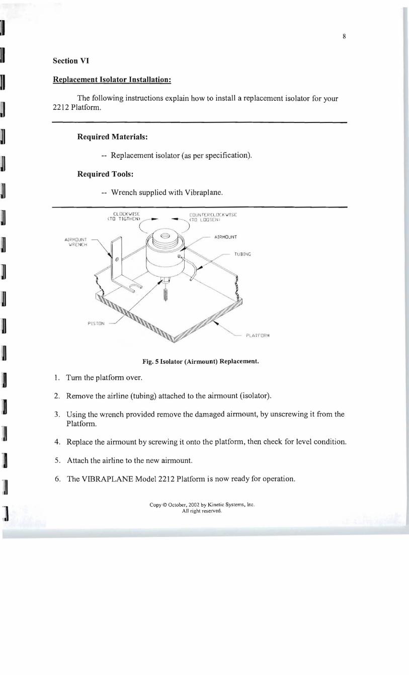