Embed Size (px)
Citation preview
Kinect and RGBD Images:Challenges and Applications
Leandro Cruz, Djalma Lucio, Luiz Velhoz
IMPA - VISGRAF Lab
Rio de Janeiro, Brazil
SIBGRAPI Tutorial - 2012
Title: Kinect and RGBD Images: Challenges and Applications
Duration: 3 hours
Tutorial Level: Intermediate
Abstract
The Kinect is a device introduced in 2010 as an accessory of XBox 360. The data
acquired has di�erent and complementary natures, combining geometry with visual
attributes. For this reason, the Kinect is a �exible tool that can be used in appli-
cations of several areas, such as: Computer Graphics, Image Processing, Computer
Vision and Human-Machine Interaction. In this way, the Kinect is a widely used
device in the industry (games, robotics, theater performers, natural interfaces, etc.)
and in research.
Initially in this tutorial we will present the main techniques related to the acqui-
sition of data: capturing, representation and �ltering. The data consists of a colored
image (RGB) and depth information (D). This structure is called RGBD Image.
After that, we will talk about tools available for developing applications on various
platforms. We will also discuss some recent developed projects based on RGBD Im-
ages. In particular, those related to Object Recognition, 3D Reconstruction, and
Interaction.
In this tutorial, we will show some researches, developed by the academic com-
munity, and some projects developed for the industry. We intend to show the basic
principles to begin developing applications using Kinect, and present some projects
developed at the VISGRAF Lab. And �nally, we intend to discuss the new possibil-
ities, challenges and trends raised by Kinect.
1
Contents
1 Introduction 8
2 A Bit of History 10
2.1 Milo and Kate . . . . . . . . . . . . . . . . . . . . . . . . . . . . . . . 11
2.2 Kinect Hacking . . . . . . . . . . . . . . . . . . . . . . . . . . . . . . 12
2.3 Tools Chronology . . . . . . . . . . . . . . . . . . . . . . . . . . . . . 13
2.4 Awards . . . . . . . . . . . . . . . . . . . . . . . . . . . . . . . . . . . 13
3 The Kinect Device 14
3.1 Depth Sensing System . . . . . . . . . . . . . . . . . . . . . . . . . . 14
3.2 RGB Camera . . . . . . . . . . . . . . . . . . . . . . . . . . . . . . . 15
3.3 Motor, Accelerometer and Microphones . . . . . . . . . . . . . . . . . 15
3.4 Other Devices . . . . . . . . . . . . . . . . . . . . . . . . . . . . . . . 16
4 Data Acquisition 17
4.1 Capturing . . . . . . . . . . . . . . . . . . . . . . . . . . . . . . . . . 17
4.2 RGBD Representation . . . . . . . . . . . . . . . . . . . . . . . . . . 18
4.3 Filtering . . . . . . . . . . . . . . . . . . . . . . . . . . . . . . . . . . 19
5 Tools 22
5.1 OpenKinect . . . . . . . . . . . . . . . . . . . . . . . . . . . . . . . . 22
5.2 Microsoft Kinect for Windows . . . . . . . . . . . . . . . . . . . . . . 23
5.3 OpenNI . . . . . . . . . . . . . . . . . . . . . . . . . . . . . . . . . . 23
2
5.3.1 Concepts . . . . . . . . . . . . . . . . . . . . . . . . . . . . . . 24
5.3.2 Modules . . . . . . . . . . . . . . . . . . . . . . . . . . . . . . 24
5.3.3 Production Nodes . . . . . . . . . . . . . . . . . . . . . . . . . 26
5.3.4 Production Chains . . . . . . . . . . . . . . . . . . . . . . . . 27
5.3.5 Capabilities . . . . . . . . . . . . . . . . . . . . . . . . . . . . 27
5.3.6 Licensing . . . . . . . . . . . . . . . . . . . . . . . . . . . . . 28
5.3.7 Framework Utilities . . . . . . . . . . . . . . . . . . . . . . . . 28
5.4 PCL . . . . . . . . . . . . . . . . . . . . . . . . . . . . . . . . . . . . 29
5.5 Comparing tools . . . . . . . . . . . . . . . . . . . . . . . . . . . . . 30
6 RGBD Database 31
7 RGBD Researches 33
7.1 3D Reconstruction . . . . . . . . . . . . . . . . . . . . . . . . . . . . 33
7.2 Augmented Reality . . . . . . . . . . . . . . . . . . . . . . . . . . . . 35
7.3 Image Processing . . . . . . . . . . . . . . . . . . . . . . . . . . . . . 36
7.4 Interaction . . . . . . . . . . . . . . . . . . . . . . . . . . . . . . . . . 37
7.5 Robotic . . . . . . . . . . . . . . . . . . . . . . . . . . . . . . . . . . 38
7.6 Object Recognition . . . . . . . . . . . . . . . . . . . . . . . . . . . . 38
8 Applications 40
8.1 VISGRAF Lab Projects . . . . . . . . . . . . . . . . . . . . . . . . . 41
8.1.1 Lambe-lambe 3D . . . . . . . . . . . . . . . . . . . . . . . . . 41
8.1.2 Kinect Stereo Viewer . . . . . . . . . . . . . . . . . . . . . . . 41
8.1.3 GrabCut+D . . . . . . . . . . . . . . . . . . . . . . . . . . . . 42
8.1.4 Feature track and detection: detect and track features in a
RGBD video . . . . . . . . . . . . . . . . . . . . . . . . . . . . 42
8.1.5 ACDC . . . . . . . . . . . . . . . . . . . . . . . . . . . . . . . 42
8.1.6 INTEGRARTE ENTREGARTE . . . . . . . . . . . . . . . . 42
9 Conclusion 43
3
Chapter 1
Introduction
Kinect appeared on November 4, 2010, as an accessory to Xbox 360 Console. It is
a device developed by the PrimeSense Company in collaboration with Microsoft. In
January of 2012, more than 18 million units were sold. In February of 2012, a version
for Windows was released.
Its announcement in 2009 caused great expectations in the Computer Graphics
and Computer Vision academic communities. The product promised a new way to
interact in games, completely based on gestures and voice (without any other type
of control). Since it was presented, Kinect became a device widely used in industry
(games, robotics, theater performers, natural interfaces, etc.) and in research.
The main idea of this survey is to present techniques and technologies used by
Kinect and its applications in industry and research. We will discuss about the new
possibilities introduced by Kinect, the main challenges and trends raised for this
device.
Kinect has an RGB camera and an infrared (IR) emitter and camera. They are
capable of capturing a colored image and depth of each pixel in the scene. These data
contain visual and geometric informations of the scene. They are complementary
and they allow us to do tasks that are di�cult, if not impossible, when we use only
images. Most of the image processing systems are based only on the color channels
of the images. Nevertheless, others image attributes can be used for processing, for
instance: depth, normal, luminance, etc. These attributes contain informations that
4
further, or they allow, implementing some procedures that are hard, if not impossible,
using only colors. Accordingly, the information acquired by Kinect (RGB + Depth)
has a structure that creates a new way to process images. In this survey, we will
explore the new possibilities generated by this structure, called RGBD Image. An
example of these possibilities is real time tracking of a human skeleton (a structure
widely used on gesture-based interactions).
Fisrt, in Section 2, we will present the birth and the launch of Kinect. Second,
in Section 3, we will show the Kinect architecture and its sensor. Third, in Section
4, we will discuss data capturing, representation and �ltering. After, in Section 5 we
will present some tools which could be used in developing of the applications using
Kinect. There are several internet databases of RGBD Images. We will list some of
this databases in Section 6. Beside of this, we will also discuss about some research
(in Object Recognition, 3D Reconstruction, Augmented Reality, Image Processing,
Robotic, and Interaction) developed using RGBD images, in Section 7. Finally, we
will talk about some applications developed using Kinect, in Section 8.
5
Chapter 2
A Bit of History
The depth sensor used in Kinect was developed by Zeev Zalevsky, Alexander Shpunt,
Aviad Maizels and Javier Garcia, in 2005 [1]. Kinect was o�cially announced on June
1, 2009, under the name �Project Natal�, at E3 (Electronic Entertainment Expo).
The name �Natal� was a reference to the Brazilian city Natal. One of the Microsoft
directors of the project, Alex Kipman, is Brazilian and chose the city name, that
means `birth' in latim, to name the project.
Initially, the main functionality of the Kinect was to be a tool to the user to
interact with Xbox 360 using gestures and spoken commands. For this reason, the
sensor is capable of capturing data at 640x480 pixels in 30Hz. With the depth data, it
is possible to obtain a skeleton of who is in front of the sensor. And with the skeleton,
it is possible to de�ne user gestures. The way how it is possible to infer user gestures
using Kinect only was revealed in January 2010. In the case of launch, three demos
were shown: Ricochet, Paint Party and Milo & Kate. The way how these demos
were implemented was unknown and, because of this, caused great expectations. At
E3, �fteen games for Xbox 360 that would be launched on November 2010 were
announced. Figure 2.1 shows these games.
Ricochet is a game that has an avatar that copies the user moves. The goal is
hitting virtual balls. Paint Party is a paint program. The user has a few brushes and
�lls to draw. Milo & Kate is the most complex demo shown in this occasion. In this
demo, the user can interact with a virtual 10-year-old child (Milo) or a dog (Kate).
6
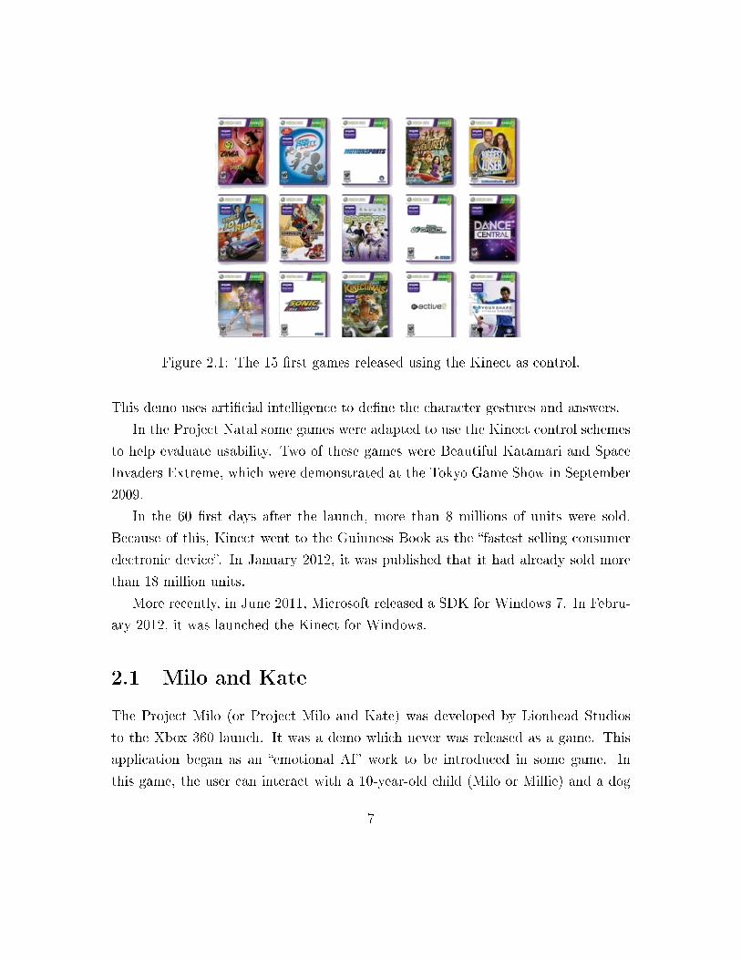
Figure 2.1: The 15 �rst games released using the Kinect as control.
This demo uses arti�cial intelligence to de�ne the character gestures and answers.
In the Project Natal some games were adapted to use the Kinect control schemes
to help evaluate usability. Two of these games were Beautiful Katamari and Space
Invaders Extreme, which were demonstrated at the Tokyo Game Show in September
2009.
In the 60 �rst days after the launch, more than 8 millions of units were sold.
Because of this, Kinect went to the Guinness Book as the �fastest selling consumer
electronic device�. In January 2012, it was published that it had already sold more
than 18 million units.
More recently, in June 2011, Microsoft released a SDK for Windows 7. In Febru-
ary 2012, it was launched the Kinect for Windows.
2.1 Milo and Kate
The Project Milo (or Project Milo and Kate) was developed by Lionhead Studios
to the Xbox 360 launch. It was a demo which never was released as a game. This
application began as an �emotional AI� work to be introduced in some game. In
this game, the user can interact with a 10-year-old child (Milo or Millie) and a dog
7
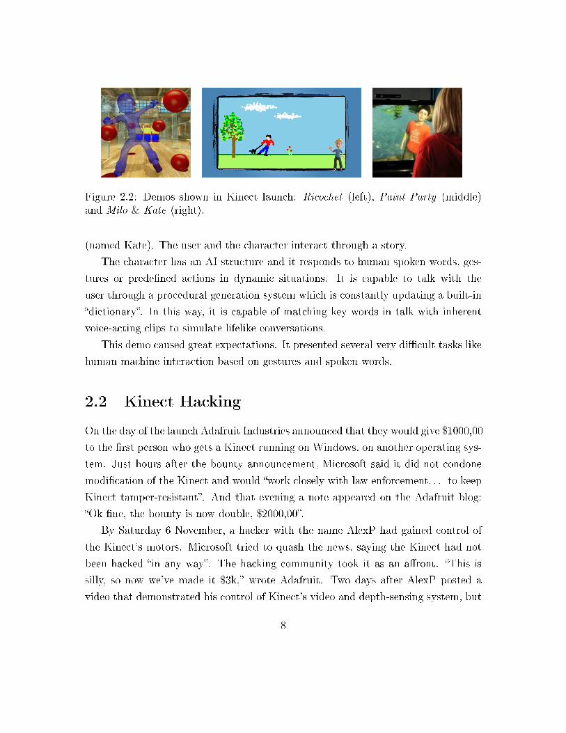
Figure 2.2: Demos shown in Kinect launch: Ricochet (left), Paint Party (middle)and Milo & Kate (right).
(named Kate). The user and the character interact through a story.
The character has an AI structure and it responds to human spoken words, ges-
tures or prede�ned actions in dynamic situations. It is capable to talk with the
user through a procedural generation system which is constantly updating a built-in
�dictionary�. In this way, it is capable of matching key words in talk with inherent
voice-acting clips to simulate lifelike conversations.
This demo caused great expectations. It presented several very di�cult tasks like
human machine interaction based on gestures and spoken words.
2.2 Kinect Hacking
On the day of the launch Adafruit Industries announced that they would give $1000,00
to the �rst person who gets a Kinect running on Windows, on another operating sys-
tem. Just hours after the bounty announcement, Microsoft said it did not condone
modi�cation of the Kinect and would �work closely with law enforcement. . . to keep
Kinect tamper-resistant�. And that evening a note appeared on the Adafruit blog:
�Ok �ne, the bounty is now double, $2000,00�.
By Saturday 6 November, a hacker with the name AlexP had gained control of
the Kinect's motors. Microsoft tried to quash the news, saying the Kinect had not
been hacked �in any way�. The hacking community took it as an a�ront. �This is
silly, so now we've made it $3k,� wrote Adafruit. Two days after AlexP posted a
video that demonstrated his control of Kinect's video and depth-sensing system, but
8
refused to release his code unless the community put together $10.000,00 to fund his
research.
While other hackers were still working on getting the Kinect working on the
November 9, Héctor blew past everyone when Kinect was released in Spain on Novem-
ber 10th. At 10 am, he bought his Kinect. At 11 am, he caught up with the current
level of work. At noon, he claimed victory, demonstrating video and depth data
streaming from the device.
2.3 Tools Chronology
Hector Martin open sourced his libfreenect code and made it available on Github.
The initial commit to OpenKinect/libfreenect was made on November 10th 2010.
About a month later, on December 9th, PrimeSense, the manufacturer of the
PrimeSensor camera reference design used by Microsoft to create the Kinect, ac-
knowledging the interest and achievements of the open source community, decided
to open source its own driver and framework API (OpenNI), and to release binaries
for their NITE skeletal tracking module and other applications.
On February 21, 2011 Microsoft announced that it would release a non-commercial
Kinect software development kit for Windows in spring 2011, which was released for
Windows 7 on June 16, 2011 in 12 countries. In March 2012, Microsoft announced
that next version of the Kinect for Windows would be available in May 2012. Kinect
for Windows 1.5 was released on May 21, 2012.
2.4 Awards
In 2011, Kinect won the MacRobert award for engineering innovation, for the work
on machine learning on motion capture. In the same year, it won T3's "Gadget of
Year" and "Gaming Gadget of the year". The Microsoft SDK was ranked second in
"The Most Innovative Tech Products of 2011" at Popular Mechanics Breakthrough
Awards ceremony.
9
Chapter 3
The Kinect Device
In Kinect origin, the software technology was internally developed by Rare, a sub-
sidiary of Microsoft Game Studios, and the depth camera technology by Israeli devel-
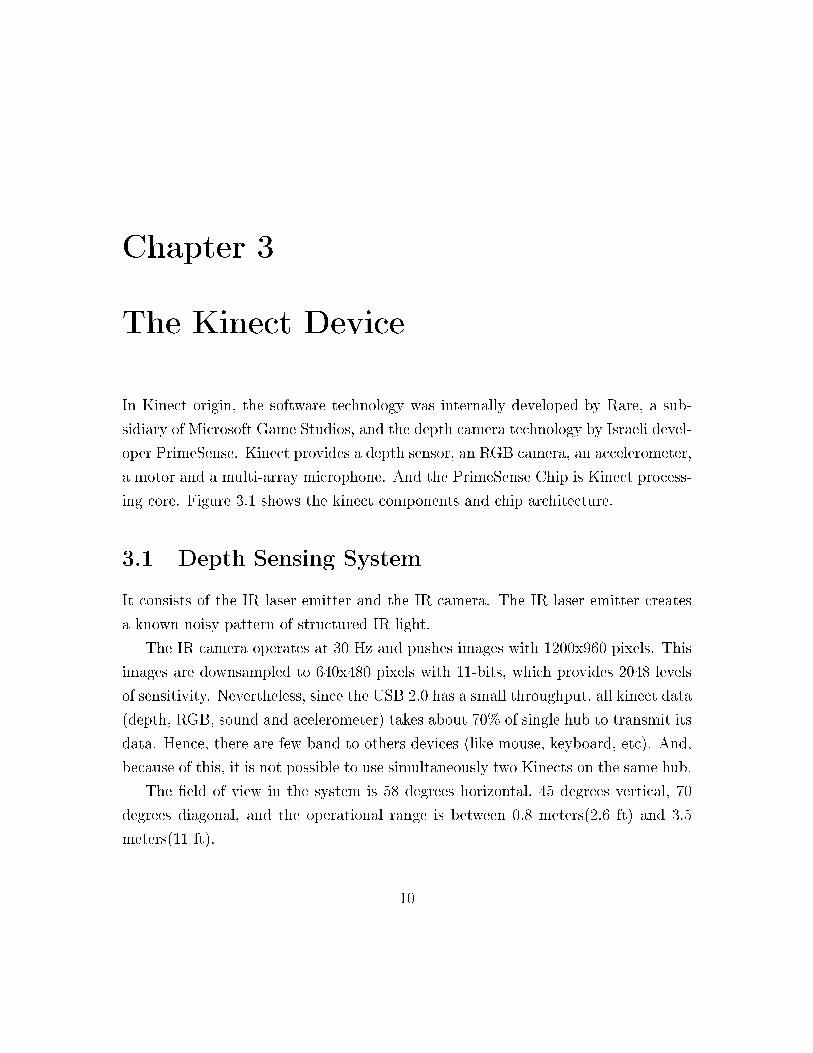
oper PrimeSense. Kinect provides a depth sensor, an RGB camera, an accelerometer,
a motor and a multi-array microphone. And the PrimeSense Chip is Kinect process-
ing core. Figure 3.1 shows the kinect components and chip architecture.
3.1 Depth Sensing System
It consists of the IR laser emitter and the IR camera. The IR laser emitter creates
a known noisy pattern of structured IR light.
The IR camera operates at 30 Hz and pushes images with 1200x960 pixels. This
images are downsampled to 640x480 pixels with 11-bits, which provides 2048 levels
of sensitivity. Nevertheless, since the USB 2.0 has a small throughput, all kinect data
(depth, RGB, sound and acelerometer) takes about 70% of single hub to transmit its
data. Hence, there are few band to others devices (like mouse, keyboard, etc). And,
because of this, it is not possible to use simultaneously two Kinects on the same hub.
The �eld of view in the system is 58 degrees horizontal, 45 degrees vertical, 70
degrees diagonal, and the operational range is between 0.8 meters(2.6 ft) and 3.5
meters(11 ft).
10
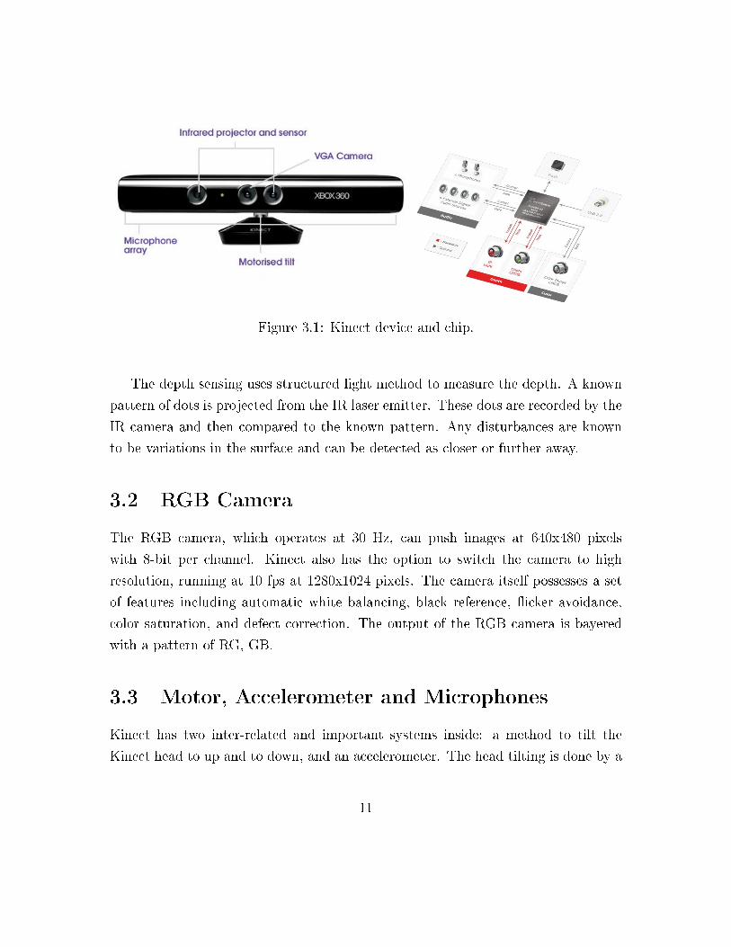
Figure 3.1: Kinect device and chip.
The depth sensing uses structured light method to measure the depth. A known
pattern of dots is projected from the IR laser emitter. These dots are recorded by the
IR camera and then compared to the known pattern. Any disturbances are known
to be variations in the surface and can be detected as closer or further away.
3.2 RGB Camera
The RGB camera, which operates at 30 Hz, can push images at 640x480 pixels
with 8-bit per channel. Kinect also has the option to switch the camera to high
resolution, running at 10 fps at 1280x1024 pixels. The camera itself possesses a set
of features including automatic white balancing, black reference, �icker avoidance,
color saturation, and defect correction. The output of the RGB camera is bayered
with a pattern of RG, GB.
3.3 Motor, Accelerometer and Microphones
Kinect has two inter-related and important systems inside: a method to tilt the
Kinect head to up and to down, and an accelerometer. The head tilting is done by a
11
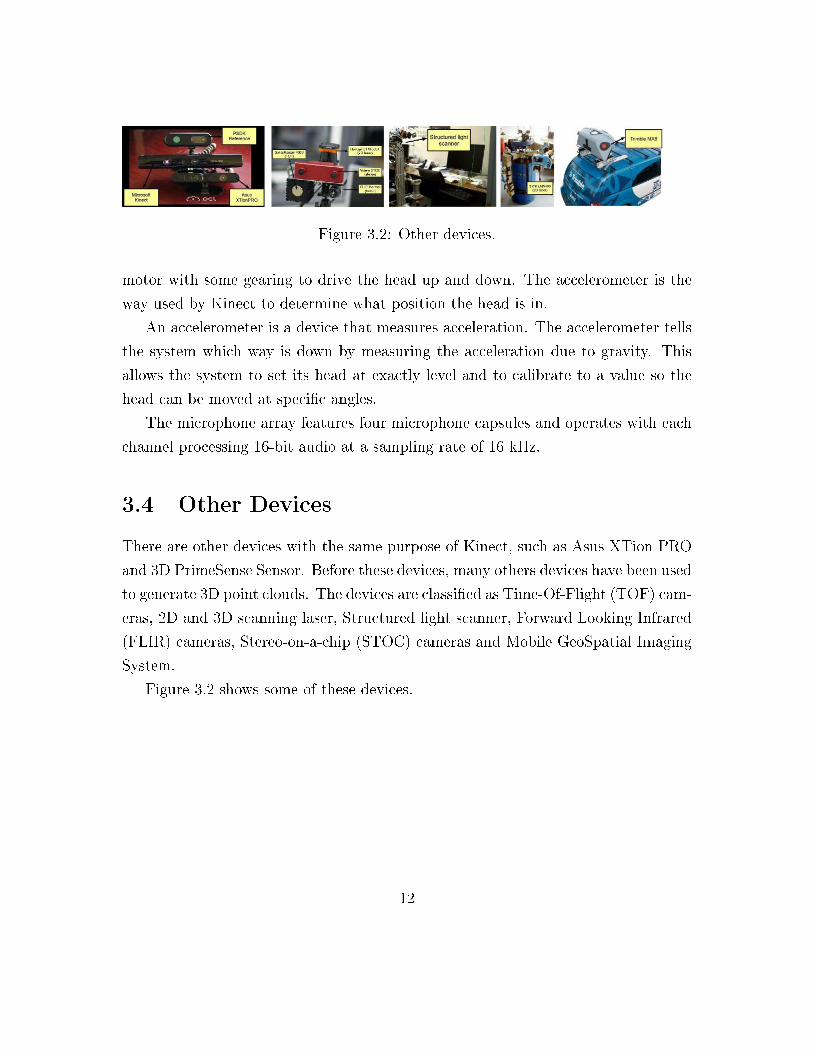
Figure 3.2: Other devices.
motor with some gearing to drive the head up and down. The accelerometer is the
way used by Kinect to determine what position the head is in.
An accelerometer is a device that measures acceleration. The accelerometer tells
the system which way is down by measuring the acceleration due to gravity. This
allows the system to set its head at exactly level and to calibrate to a value so the
head can be moved at speci�c angles.
The microphone array features four microphone capsules and operates with each
channel processing 16-bit audio at a sampling rate of 16 kHz.
3.4 Other Devices
There are other devices with the same purpose of Kinect, such as Asus XTion PRO
and 3D PrimeSense Sensor. Before these devices, many others devices have been used
to generate 3D point clouds. The devices are classi�ed as Time-Of-Flight (TOF) cam-
eras, 2D and 3D scanning laser, Structured light scanner, Forward Looking Infrared
(FLIR) cameras, Stereo-on-a-chip (STOC) cameras and Mobile GeoSpatial Imaging
System.
Figure 3.2 shows some of these devices.
12
Chapter 4
Data Acquisition
The colored image is obtained by a RGB camera. The depth measurement is done
using an infrared emitter and camera. The computation is done using structured
light. Because Kinect uses infrared light it is an indoor device (since outdoor the
depth measurement quality is a�ected). Another infrared problem is that some
materials do not re�ect well this light. Beside this, it is advised to stay about 1.8m
away from Kinect, in the case of using it for interaction.
In this section, we will discuss the capturing process (mainly depth measurements
with structured light method), the data representation and data �ltering.
4.1 Capturing
As said, the depth measurement is done using a structured light technique. This
approach consists in projecting a pattern of pixels in the scene and capturing the
deformation of projection, that will allows us to compute the pixel distances (depths).
It is necessary to calibrate the IR emitter and camera to perform this calculation (the
distance between Kinect IR emitter and camera is 7.5cm). This calculation consists
of a triangulation based in emitter, camera and pixel positions.
The pattern used in Kinect is a PrimeSense patent. Some people did some ex-
periments to try understand better this one. It is known that the pattern is based
13
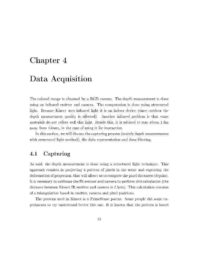
on speckle of infrared lights. It is generated from a set of di�raction gratings, with
special care to lessen the e�ect of zero-order propagation of a center bright dot.
For each pixel in the IR image, a small correlation window (9x9 or 9x7) is used to
compare the local pattern at that pixel with the memorized pattern at that pixel and
64 neighboring pixels in a horizontal window. The best match gives an o�set from the
known depth, in terms of pixels: this is called disparity. The Kinect device performs
a further interpolation of the best match to get sub-pixel accuracy of 1/8 pixel. Given
the known depth of the memorized plane, and the disparity, an estimated depth for
each pixel can be calculated by triangulation.
A pixel in the RGB image refers to a di�erent point of the same pixel in depth
image. It is because the di�erence of position of this two cameras (2.5cm). To correct
for this di�erence it is necessary to calibrate these cameras. Some tools, like openNI,
can be used to do this correction.
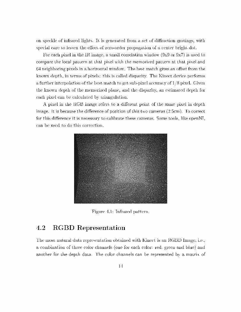
Figure 4.1: Infrared pattern.
4.2 RGBD Representation
The most natural data representation obtained with Kinect is an RGBD Image, i.e.,
a combination of three color channels (one for each color: red, green and blue) and
another for the depth data. The color channels can be represented by a matrix of
14
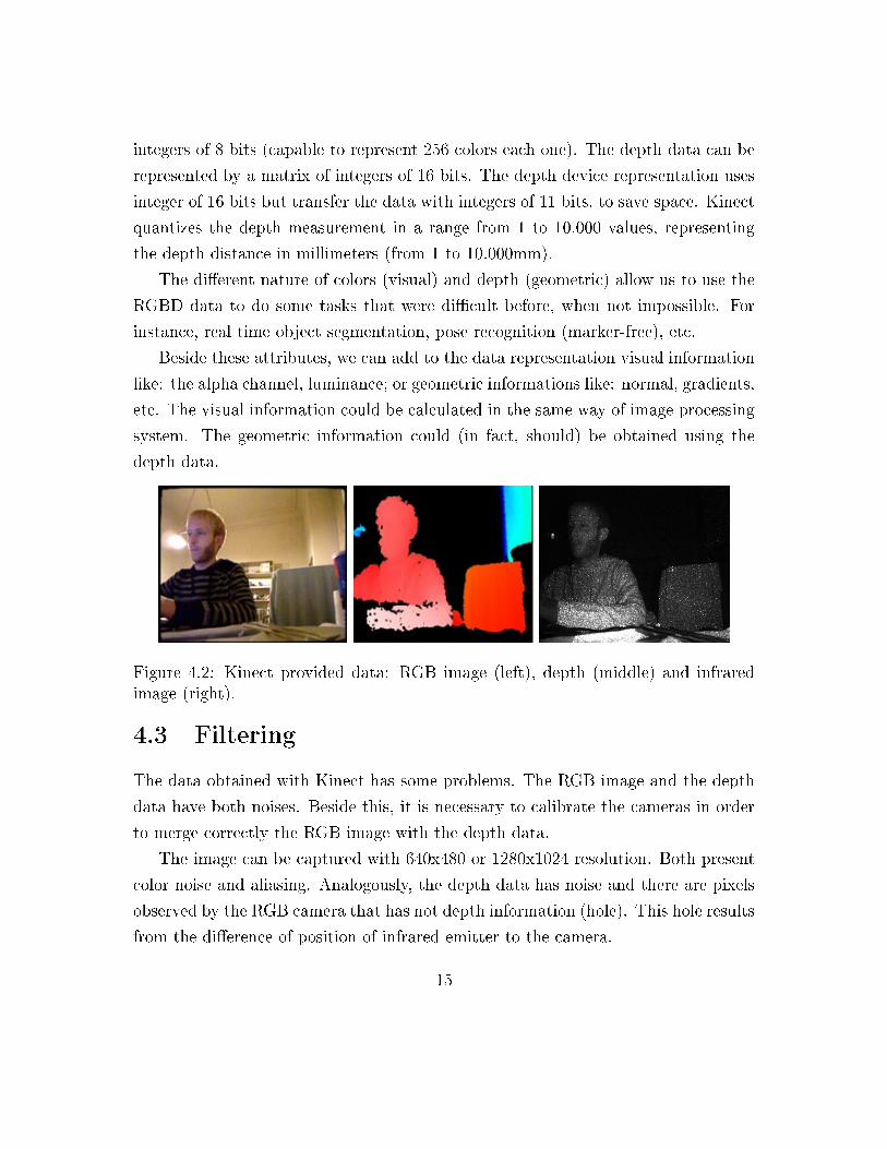
integers of 8 bits (capable to represent 256 colors each one). The depth data can be
represented by a matrix of integers of 16 bits. The depth device representation uses
integer of 16 bits but transfer the data with integers of 11 bits, to save space. Kinect
quantizes the depth measurement in a range from 1 to 10.000 values, representing
the depth distance in millimeters (from 1 to 10.000mm).
The di�erent nature of colors (visual) and depth (geometric) allow us to use the
RGBD data to do some tasks that were di�cult before, when not impossible. For
instance, real time object segmentation, pose recognition (marker-free), etc.
Beside these attributes, we can add to the data representation visual information
like: the alpha channel, luminance; or geometric informations like: normal, gradients,
etc. The visual information could be calculated in the same way of image processing
system. The geometric information could (in fact, should) be obtained using the
depth data.
Figure 4.2: Kinect provided data: RGB image (left), depth (middle) and infraredimage (right).
4.3 Filtering
The data obtained with Kinect has some problems. The RGB image and the depth
data have both noises. Beside this, it is necessary to calibrate the cameras in order
to merge correctly the RGB image with the depth data.
The image can be captured with 640x480 or 1280x1024 resolution. Both present
color noise and aliasing. Analogously, the depth data has noise and there are pixels
observed by the RGB camera that has not depth information (hole). This hole results
from the di�erence of position of infrared emitter to the camera.
15
We can �lter the RGB channels and the depth channel using Image Processing
methods. In this case, we can think of the depth data as a monochromatic image.
It is not the goal of this survey discuss these methods. On the other hand, we will
focus on methods that exploit the geometric structure improved by the depth data.
A naive approach to reduce the noise in the depth data is to apply a Gaussian
(or an average, or a median) �lter. This approach is very simple, and analogous to
image �ltering. However, it could change low frequency structure (edges in the raw
depth). Another approach is temporal �ltering. In this case we can calculate for each
pixel, an average of pixels in the time interval. If all objects in the scene and the
camera were �xed, this process is optimal. It maintains low frequency informations
and removes high frequency noise. A natural problem is, in almost all cases, an
impossible assumption.
Both previous approaches do not guarantee hole �lling. We can use techniques
applied to �ll holes in meshes. Assuming that the depth data is a continuous surface,
a naive technique to �ll holes is to calculate an average of its non null neighbors (the
neighborhood radius could be �xed or adaptive).
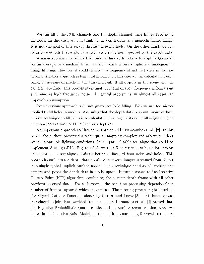
An important approach to �lter data is presented by Newcombe et. al. [2]. In this
paper, the authors presented a technique to mapping complex and arbitrary indoor
scenes in variable lighting conditions. It is a parallelizable technique that could be
implemented using GPUs. Figure 4.3 shows that Kinect raw data has a lot of noise
and holes. This technique obtains a better surface, without noise and holes. This
approach combines the depth data obtained in several images streamed from Kinect
in a single global implicit surface model. This technique consists of tracking the
camera and poses the depth data in model space. It uses a coarse-to-�ne Iterative
Closest Point (ICP) algorithm, combining the current depth frame with all other
previous observed data. For each vertex, the result on processing depends of the
number of frames captured which it contains. The �ltering processing is based on
the Signed Distance Function, shown by Curless and Levoy [3]. This function was
introduced to join data provided from a scanner. Hernandez et. al. [4] proved that,
the Bayesian Probabilistic guarantee the optimal surface reconstruction, since we
use a simple Gaussian Noise Model, on the depth measurement, for vertices that are
16
visible in all frames. It results in a simple algorithm of averaging weighted signed
distance function into a global frame. In our case, we are only interested in the local
version of this result, because the surface occlusion and SDF truncations.
First of all, they apply a bilateral �lter to the raw depth, in each frame, to
obtain a data with less noise, but preserving the discontinuities. Since the data
is a regular grid it is very easy to construct a surface based on the pixels grid.
With the �ltered vertex, they construct a surface and they calculate the normal for
each vertex (an average of all incident polygons normal, in the neighbourhood of
the vertex). After this, they de�ne a validity mask for the vertex. They compute a
multi-scale representation of the surface measurement in the pyramid form (to vertex
and normal map).
After surface measurement, this work applies the mapping and surface recon-
struction. Each consecutive frame is fused into the single 3D reconstruction using
the volumetric Truncated Signed Distance Fucntion (TSDF) [3]. Figure 4.3 shows
an example of object obtained by KinectFusion process. Observe that, although the
original frame is noisy and has holes (left) the resulting surface is connex and smooth.
The middle image is the normal map of the surface and the right image is the shaded
using the Phong model.
Figure 4.3: Data with noise and hole �ltered with KinectFusion technique.
17
Chapter 5
Tools
The main functionalities used on applications and libraries development, for Kinect,
are available on following projects: OpenNI, OpenKinect and Microsoft Kinect for
Windows. Some of libraries which use these projects as their backend implementa-
tions are OpenCV, Unity3D, PCL, RGBDemo, openframeworks, etc.
We will talk more about the OpenNI project because this is the biggest and the
most used. In particular, this tool was used on the VISGRAF Lab projects (see
Section 8).
5.1 OpenKinect
OpenKinect is an open source project that uses only open source libraries that enable
Kinect to be used with Linux, Mac and Windows. The primary OpenKinect focus
is the libfreenect software. The libfreenect software is the core library for accessing
the Microsoft Kinect USB camera. The library supports access to RGB and depth
images, Motors, Accelerometer and LED. The libfreenect library is written in C, but
provides wrappers to several languages such as Python, ActionScript, C++, C# and
Java.
The library is used as a base for some projects such as ofxKinect( openFrameworks
addon) and RGBDemo. There are samples that use libfreenect as backend for PCL.
18
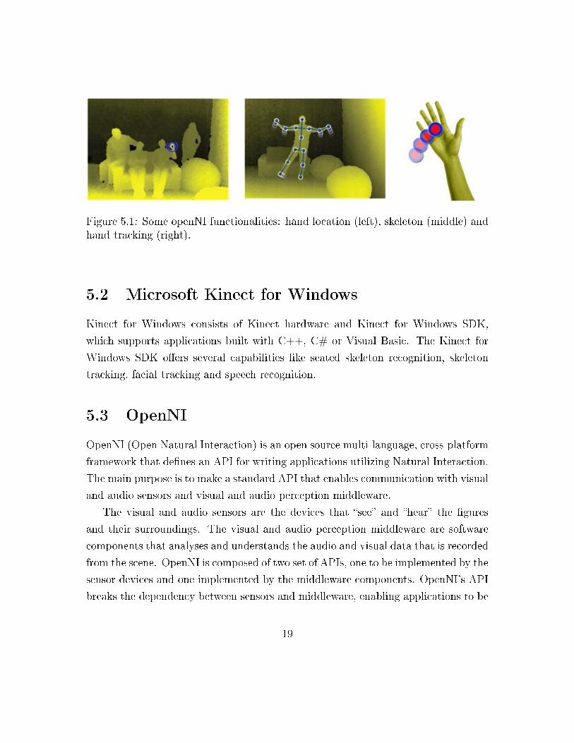
Figure 5.1: Some openNI functionalities: hand location (left), skeleton (middle) andhand tracking (right).
5.2 Microsoft Kinect for Windows
Kinect for Windows consists of Kinect hardware and Kinect for Windows SDK,
which supports applications built with C++, C# or Visual Basic. The Kinect for
Windows SDK o�ers several capabilities like seated skeleton recognition, skeleton
tracking, facial tracking and speech recognition.
5.3 OpenNI
OpenNI (Open Natural Interaction) is an open source multi-language, cross-platform
framework that de�nes an API for writing applications utilizing Natural Interaction.
The main purpose is to make a standard API that enables communication with visual
and audio sensors and visual and audio perception middleware.
The visual and audio sensors are the devices that �see� and �hear� the �gures
and their surroundings. The visual and audio perception middleware are software
components that analyses and understands the audio and visual data that is recorded
from the scene. OpenNI is composed of two set of APIs, one to be implemented by the
sensor devices and one implemented by the middleware components. OpenNI's API
breaks the dependency between sensors and middleware, enabling applications to be
19
written with no additional e�ort on top of di�erent middleware modules. OpenNI's
API also enables middleware developers to write algorithms on top of raw formats,
regardless with sensor devices had produced them, and o�ers sensor manufacturers
the capability to build sensors that power any OpenNI compliant application. Hence,
the applications can be written regardless of the sensor and middleware providers.
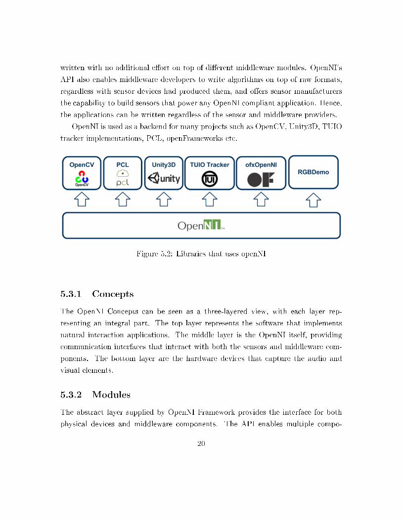
OpenNI is used as a backend for many projects such as OpenCV, Unity3D, TUIO
tracker implementations, PCL, openFrameworks etc.
Figure 5.2: Libraries that uses openNI
5.3.1 Concepts
The OpenNI Concepts can be seen as a three-layered view, with each layer rep-
resenting an integral part. The top layer represents the software that implements
natural interaction applications. The middle layer is the OpenNI itself, providing
communication interfaces that interact with both the sensors and middleware com-
ponents. The bottom layer are the hardware devices that capture the audio and
visual elements.
5.3.2 Modules
The abstract layer supplied by OpenNI Framework provides the interface for both
physical devices and middleware components. The API enables multiple compo-
20
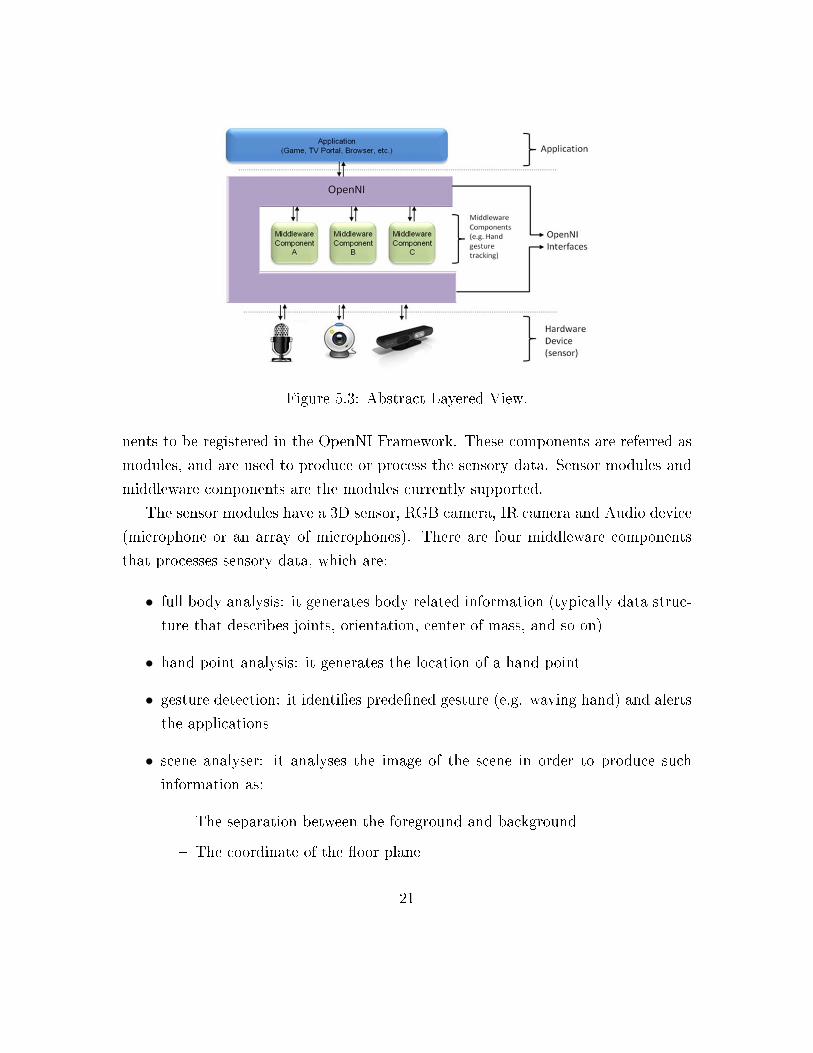
Figure 5.3: Abstract Layered View.
nents to be registered in the OpenNI Framework. These components are referred as
modules, and are used to produce or process the sensory data. Sensor modules and
middleware components are the modules currently supported.
The sensor modules have a 3D sensor, RGB camera, IR camera and Audio device
(microphone or an array of microphones). There are four middleware components
that processes sensory data, which are:
• full body analysis: it generates body related information (typically data struc-
ture that describes joints, orientation, center of mass, and so on)
• hand point analysis: it generates the location of a hand point
• gesture detection: it identi�es prede�ned gesture (e.g. waving hand) and alerts
the applications
• scene analyser: it analyses the image of the scene in order to produce such
information as:
� The separation between the foreground and background
� The coordinate of the �oor plane
21
� The individual identi�cation of the �gures in the scene
5.3.3 Production Nodes
Production nodes are de�ned by OpenNI as a set of components that have a pro-
ductive role in the data creation process required by natural interaction based ap-
plications. Each production node encapsulates the functionality that relates to the
generation of a speci�c data type. However, the API of production nodes only de�nes
the language. The logic of data generation must be implemented by the modules that
plug into OpenNI.
Each production node is a standalone unit that generates a speci�c type of data
and can provide it to any object, whether it is another production node or the
application itself. The types of production nodes are Sensor and Middleware.
Sensor related production nodes:
• Device: it represents a physical device (e.g. depth sensor or a RGB camera).
The main role of this node is to enable device con�guration.
• Depth Generator: it generates a depth-map.
• Image Generator: it generates colored image-maps.
• IR Generator: it generates IR image-maps
• Audio Generator: it generates an audio stream.
Middleware related production nodes:
• Gesture Alert Generator: it generates callbacks to the application when speci�c
gestures are identi�ed.
• Scene Analyser: it analyses a scene, including separation of the foreground
from the background, identi�cation of �gures in the scene, and detection of the
�oor plane. The main output is labelled depth map, in which each pixel holds
a label that states represents a �gure or it is part of background.
22
• Hand Point Generator: it supports hands detection and tracking. This node
generates callbacks that provide alerts when a hand point is detected, and when
a hand point currently being tracked changes its location.
• User Generator: it generates a representation of a (full or partial) body in 3D
scene.
5.3.4 Production Chains
The dependency of a node with each other to produce the required data for applica-
tion is called Production Chains. Typically an application is only interested in the
top of production node of each chain. This is the node that outputs the required
data on a practical level, for example a hand point generator.
5.3.5 Capabilities
Capabilities reveal additional functionality, enabling providers to decide individually
whether to implement an extension. A production node can be asked whether it
supports a speci�c capability. If it does, those functions can be called for that
speci�c node.
Each module can declare the capabilities it supports. Furthermore, when request-
ing enumeration of production chains, the application can specify the capabilities that
should be supported as criteria. Only modules that support the requested capability
are returned by the enumeration.
Supported capabilities:
• Alternative View: it enables any type of map generator (depth, image, IR) to
transform its data to appear as if the sensor was placed in another location.
• Cropping: it enables a map generator (depth, image, IR) to output a selected
area of the frame as opposed to the entire frame.
• Frame Sync: it enables two sensors producing frame data (for example, depth
and image) to synchronize their frames so that they arrive at the same time.
23
• Mirror: it enables mirroring of the data produced by a generator.
• Pose Detection: it enables a user generator to recognize when the user is posed
in a speci�c position.
• Skeleton: it enables a user generator to output the skeletal data of the user.
This data includes the location of the skeletal joints, the ability to track skeleton
positions and the user calibration.
• User Position: it enables a Depth Generator to optimize the output depth map
that is generated for a speci�c area of the scene.
• Error State: it enables a node to report that it is in error status.
• Lock Aware: it enables a node to be locked outside the context boundary.
• Hand Touching FOV Edge: it alerts when the hand point reaches the bound-
aries of the �eld of view.
5.3.6 Licensing
OpenNI provides a simple licensing mechanism that can be used by modules and
applications. A license is composed of a vendor name and a license key. Vendors
who want to use this mechanism can utilize their own proprietary format for the key.
The license mechanism is used by modules, to ensure that they are only used by
authorized applications.
5.3.7 Framework Utilities
Some OpenNI utilities are: USB access abstract layer, basic data type implementa-
tion (list, hash and so on), log and dump system, memory and performance pro�ling,
events and scheduling of tasks.
24
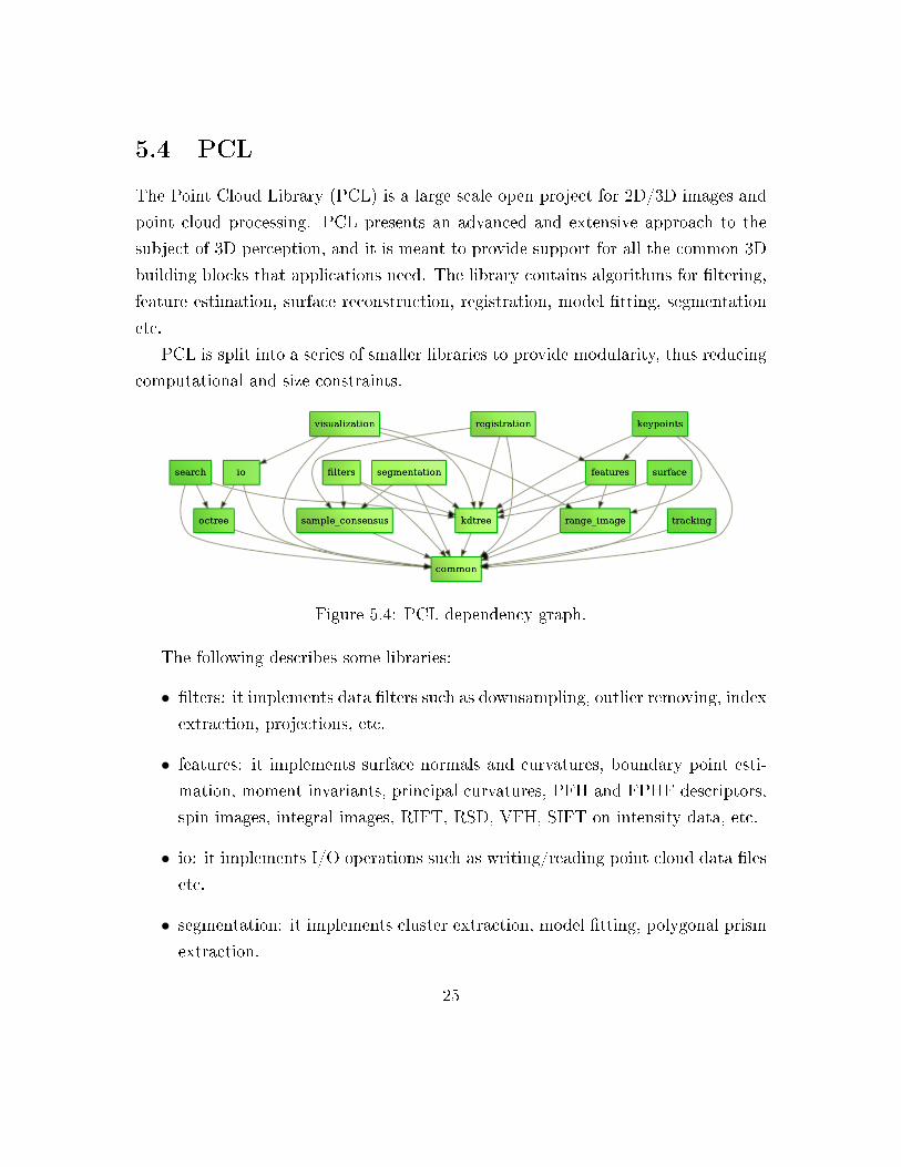
5.4 PCL
The Point Cloud Library (PCL) is a large scale open project for 2D/3D images and
point cloud processing. PCL presents an advanced and extensive approach to the
subject of 3D perception, and it is meant to provide support for all the common 3D
building blocks that applications need. The library contains algorithms for �ltering,
feature estimation, surface reconstruction, registration, model �tting, segmentation
etc.
PCL is split into a series of smaller libraries to provide modularity, thus reducing
computational and size constraints.
Figure 5.4: PCL dependency graph.
The following describes some libraries:
• �lters: it implements data �lters such as downsampling, outlier removing, index
extraction, projections, etc.
• features: it implements surface normals and curvatures, boundary point esti-
mation, moment invariants, principal curvatures, PFH and FPHF descriptors,
spin images, integral images, RIFT, RSD, VFH, SIFT on intensity data, etc.
• io: it implements I/O operations such as writing/reading point cloud data �les
etc.
• segmentation: it implements cluster extraction, model �tting, polygonal prism
extraction.
25
• registration: it implements point cloud registration methods such as ICP, etc
• keypoints: it implements di�erent keypoint extraction methods that can be
used as a preprocessing step to decide where to extract feature descriptors.
• range image: it implements supports for range images created from point cloud
datasets.
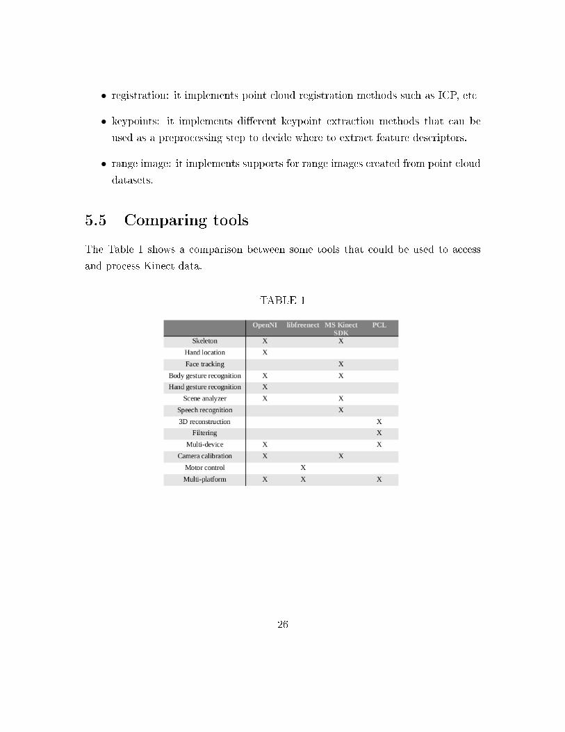
5.5 Comparing tools
The Table 1 shows a comparison between some tools that could be used to access
and process Kinect data.
TABLE 1
26
Chapter 6
RGBD Database
We said that the depth information improves new possibilities in image processing
and computer vision. Although, a drawback is to capture this data. This is not a big
problem for two reasons: Kinect is a low cost device, and there are several RGBD
datasets available on Internet. For instance, we can cite the NYU Depth Dataset
[5], RGB-D Object Dataset [6], Cornell-RGBD-Dataset [7], among others [8, 9, 10].
With this data, it is possible to do a lot of research (about RGBD Image and Video
Processing, Pattern Recognition, etc.) even if the person has not access to a Kinect.
In general, each dataset was constructed with an speci�c goal, and besides of this
they have speci�c features.
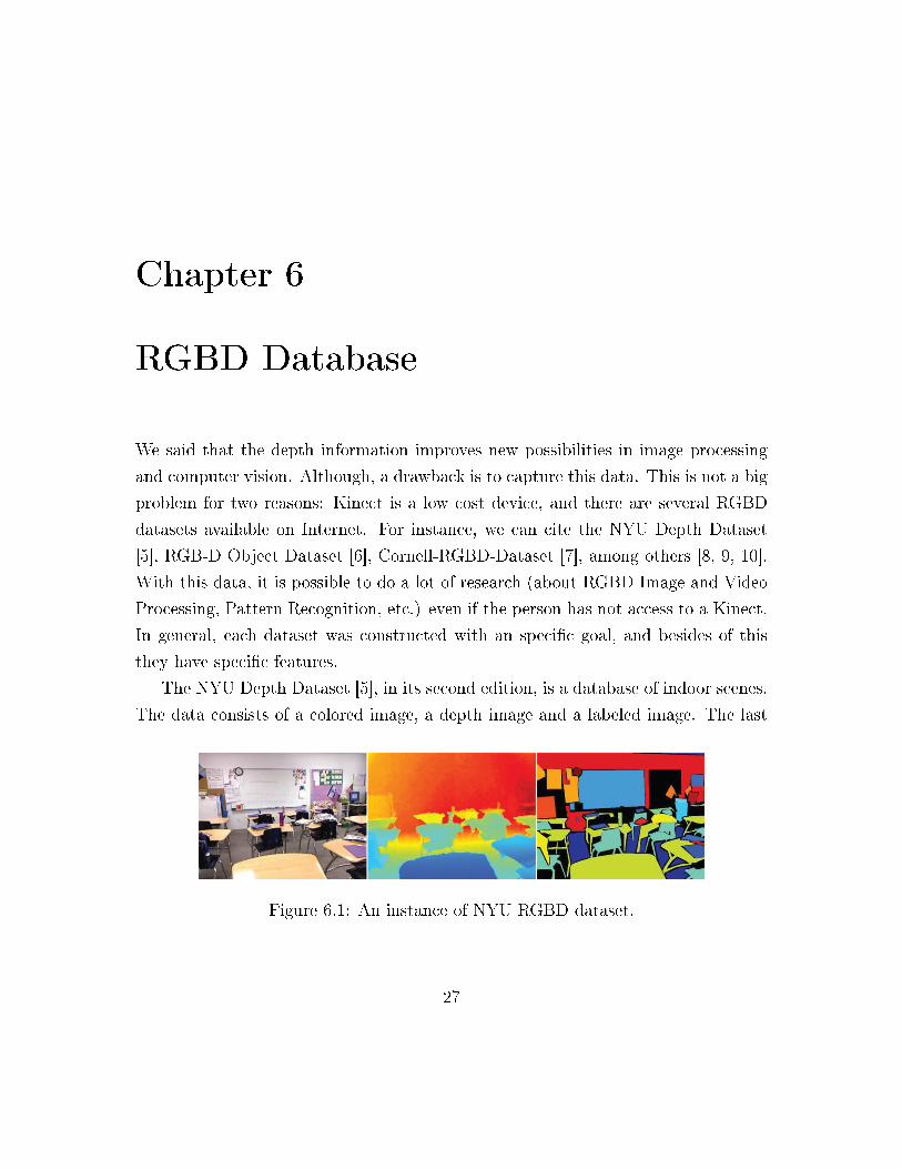
The NYU Depth Dataset [5], in its second edition, is a database of indoor scenes.
The data consists of a colored image, a depth image and a labeled image. The last
Figure 6.1: An instance of NYU RGBD dataset.
27
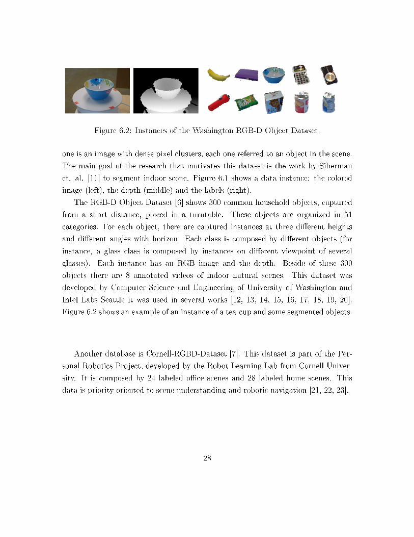
Figure 6.2: Instances of the Washington RGB-D Object Dataset.
one is an image with dense pixel clusters, each one referred to an object in the scene.
The main goal of the research that motivates this dataset is the work by Siberman
et. al. [11] to segment indoor scene. Figure 6.1 shows a data instance: the colored
image (left), the depth (middle) and the labels (right).
The RGB-D Object Dataset [6] shows 300 common household objects, captured
from a short distance, placed in a turntable. These objects are organized in 51
categories. For each object, there are captured instances at three di�erent heights
and di�erent angles with horizon. Each class is composed by di�erent objects (for
instance, a glass class is composed by instances on di�erent viewpoint of several
glasses). Each instance has an RGB image and the depth. Beside of these 300
objects there are 8 annotated videos of indoor natural scenes. This dataset was
developed by Computer Science and Engineering of University of Washington and
Intel Labs Seattle it was used in several works [12, 13, 14, 15, 16, 17, 18, 19, 20].
Figure 6.2 shows an example of an instance of a tea-cup and some segmented objects.
Another database is Cornell-RGBD-Dataset [7]. This dataset is part of the Per-
sonal Robotics Project, developed by the Robot Learning Lab from Cornell Univer-
sity. It is composed by 24 labeled o�ce scenes and 28 labeled home scenes. This
data is priority oriented to scene understanding and robotic navigation [21, 22, 23].
28
Chapter 7
RGBD Researches
7.1 3D Reconstruction
3D scanning has been a very popular task in the last years. There are several
technologies that could be used to capture the geometry of an object (or a scene),
such that: LIDAR, time of �ight, stereo cameras, and structured light. Nevertheless,
a scanner is an expensive and a big machine. On the other hand, Kinect is a low
cost and handheld device capable of capturing, in real time, geometry and colors of
a scene. Naturally, there is a tradeo�. Kinect data resolution is typically 640x480.
It is lower than most of the scanners. However, it is enough for several applications.
Furthermore, we can infer better data from the captured one, i.e., reconstructing a
surface from the depth data.
3D reconstruction is a task that has motivated much research in the last years.
KinectFusion [2, 24] is a 3D reconstruction project that creates a dense surface,
without artifacts, from a set of Kinect frames. We can apply this 3D model in
several applications in Augmented Reality, Robotic Navigation, Image Processing,
etc.
The two main contributions of the work by Newcombe et. al. [2] is dense surface
mapping and camera tracking. This work creates a dense surface fusing the live
depth frame to the already construct 3D model. The sensor tracking relative to
29
global model uses a coarse-to-�ne Iterative Closest Point (ICP) [25, 26] to calculate
the 6 degrees of freedom of the camera. The surface mapping is done using a Signed
Distance Function [3].
This method consists of four steps:
• Surface Measurement: creation of vertex and normal map pyramid of the
depth that comes from Kinect;
• Surface Reconstruction Update: The fusion of current frame with global
model already reconstructed;
• Surface Prediction: Closing loop between mapping and localization by track-
ing the position of the current frame against the global model;
• Sensor Pose Estimation: camera tracking.
Izadi et. al. [24] shows how to implement the KinectFusion procedures using
generic programming in the GPU. It enables a real-time 3D reconstruction system.
The KinectFusion algorithm to handheld scanning scenes with Kinect this is
available in PCL library.
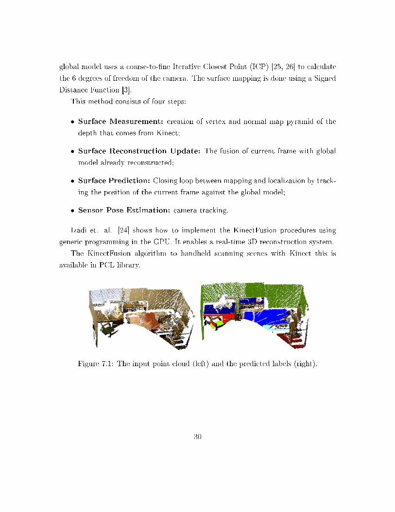
Figure 7.1: The input point cloud (left) and the predicted labels (right).
30
7.2 Augmented Reality
The depth data can also be used to help the creation of systems of Augmented Reality
(AR). Using this data it is possible to construct a marker-free application to AR.
The 3D scene model obtained by KinectFusion is an example of this help.
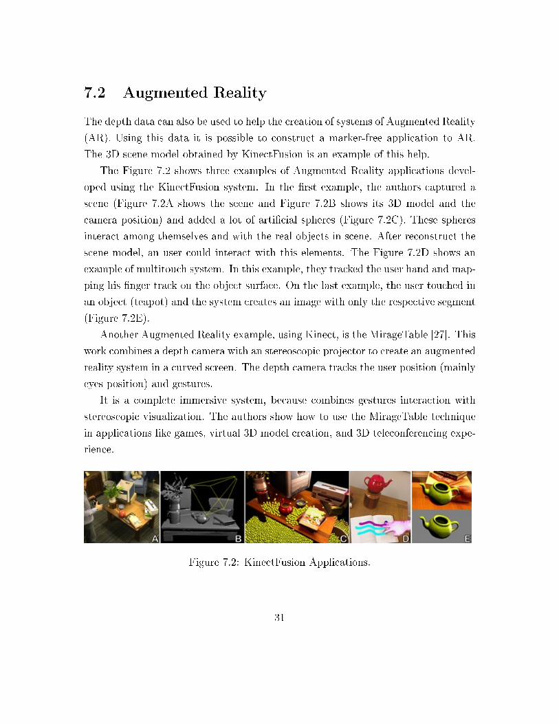
The Figure 7.2 shows three examples of Augmented Reality applications devel-
oped using the KinectFusion system. In the �rst example, the authors captured a
scene (Figure 7.2A shows the scene and Figure 7.2B shows its 3D model and the
camera position) and added a lot of arti�cial spheres (Figure 7.2C). These spheres
interact among themselves and with the real objects in scene. After reconstruct the
scene model, an user could interact with this elements. The Figure 7.2D shows an
example of multitouch system. In this example, they tracked the user hand and map-
ping his �nger track on the object surface. On the last example, the user touched in
an object (teapot) and the system creates an image with only the respective segment
(Figure 7.2E).
Another Augmented Reality example, using Kinect, is the MirageTable [27]. This
work combines a depth camera with an stereoscopic projector to create an augmented
reality system in a curved screen. The depth camera tracks the user position (mainly
eyes position) and gestures.
It is a complete immersive system, because combines gestures interaction with
stereoscopic visualization. The authors show how to use the MirageTable technique
in applications like games, virtual 3D model creation, and 3D teleconferencing expe-
rience.
Figure 7.2: KinectFusion Applications.
31
7.3 Image Processing
A di�cult task in Image Processing is Image Segmentation (using only the color
information). Adding the depth channel, this problem becomes simpler because
we can de�ne the segment boundary like the edges on depth data. However, as
already mentioned, the depth data has several problems, such as noise and holes. In
particular, in the silhouettes of these objects, these problems are very recurring.
If we have a good method to �x the depth problems, the segmentation task
becomes easy. Otherwise, we can use the depth data to help traditional segmentation
methods like Intelligent Scissor or Graph Cut.
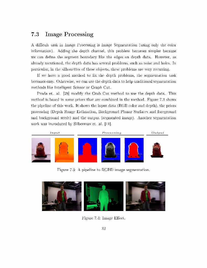
Prada et. al. [28] modify the Grab Cut method to use the depth data. This
method is based in some priors that are combined in the method. Figure 7.3 shows
the pipeline of this work. It shows the input data (RGB color and depth), the priors
processing (Depth Range Estimation, Background Planar Surfaces and foreground
and background seeds) and the output (segmented image). Another segmentation
work was introduced by Silberman et. al. [11].
Figure 7.3: A pipeline to RGBD image segmentation.
Figure 7.4: Image E�ect.
32
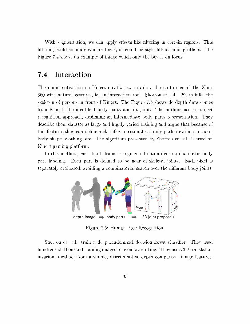
With segmentation, we can apply e�ects like �ltering in certain regions. This
�ltering could simulate camera focus, or could be style �lters, among others. The
Figure 7.4 shows an example of image which only the boy is on focus.
7.4 Interaction
The main motivation on Kinect creation was to do a device to control the Xbox
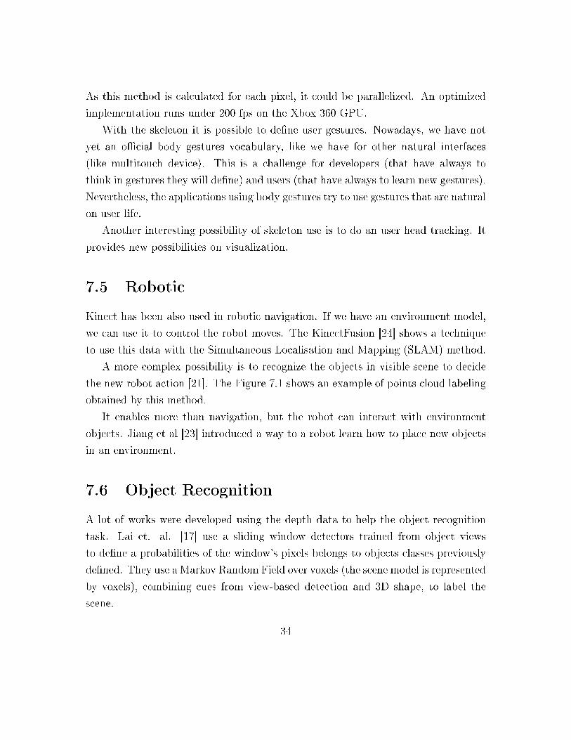
360 with natural gestures, ie, an interaction tool. Shotton et. al. [29] to infer the
skeleton of persons in front of Kinect. The Figure 7.5 shows de depth data comes
from Kinect, the identi�ed body parts and its joint. The authors use an object
recognition approach, designing an intermediate body parts representation. They
describe them dataset as large and highly varied training and argue that because of
this features they can de�ne a classi�er to estimate a body parts invariant to pose,
body shape, clothing, etc. The algorithm presented by Shotton et. al. is used on
Kinect gaming platform.
In this method, each depth frame is segmented into a dense probabilistic body
part labeling. Each part is de�ned to be near of skeletal joints. Each pixel is
separately evaluated, avoiding a combinatorial search over the di�erent body joints.
Figure 7.5: Human Pose Recognition.
Shotton et. al. train a deep randomized decision forest classi�er. They used
hundreds oh thousand training images to avoid over�tting. They use a 3D translation
invariant method, from a simple, discriminative depth comparison image features.
33
As this method is calculated for each pixel, it could be parallelized. An optimized
implementation runs under 200 fps on the Xbox 360 GPU.
With the skeleton it is possible to de�ne user gestures. Nowadays, we have not
yet an o�cial body gestures vocabulary, like we have for other natural interfaces
(like multitouch device). This is a challenge for developers (that have always to
think in gestures they will de�ne) and users (that have always to learn new gestures).
Nevertheless, the applications using body gestures try to use gestures that are natural
on user life.
Another interesting possibility of skeleton use is to do an user head tracking. It
provides new possibilities on visualization.
7.5 Robotic
Kinect has been also used in robotic navigation. If we have an environment model,
we can use it to control the robot moves. The KinectFusion [24] shows a technique
to use this data with the Simultaneous Localisation and Mapping (SLAM) method.
A more complex possibility is to recognize the objects in visible scene to decide
the new robot action [21]. The Figure 7.1 shows an example of points cloud labeling
obtained by this method.
It enables more than navigation, but the robot can interact with environment
objects. Jiang et al [23] introduced a way to a robot learn how to place new objects
in an environment.
7.6 Object Recognition
A lot of works were developed using the depth data to help the object recognition
task. Lai et. al. [17] use a sliding window detectors trained from object views
to de�ne a probabilities of the window's pixels belongs to objects classes previously
de�ned. They use a Markov Random Field over voxels (the scene model is represented
by voxels), combining cues from view-based detection and 3D shape, to label the
scene.
34
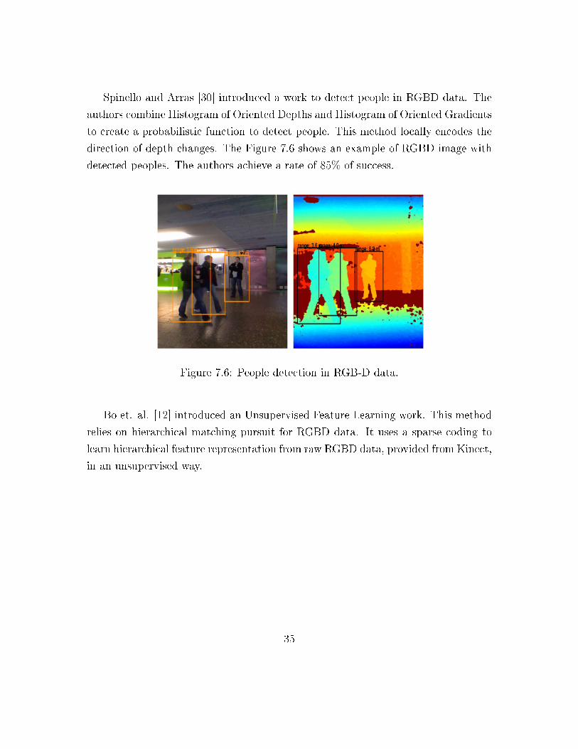
Spinello and Arras [30] introduced a work to detect people in RGBD data. The
authors combine Histogram of Oriented Depths and Histogram of Oriented Gradients
to create a probabilistic function to detect people. This method locally encodes the
direction of depth changes. The Figure 7.6 shows an example of RGBD image with
detected peoples. The authors achieve a rate of 85% of success.
Figure 7.6: People detection in RGB-D data.
Bo et. al. [12] introduced an Unsupervised Feature Learning work. This method
relies on hierarchical matching pursuit for RGBD data. It uses a sparse coding to
learn hierarchical feature representation from raw RGBD data, provided from Kinect,
in an unsupervised way.
35
Chapter 8
Applications
Although the main motivation of Kinect is its use on games of Xbox 360, it is not
only limited to this kind of applications. There are several other possibilities of to use
the Kinect: robot navigation and control, entertainment (like shows), and interaction
(on other platforms besides Kinect).
We can cite some speci�c examples, such as, a police o�cer using gestures and
word commands to remotely control a robot, exploring a building that may contain
explosives. In the healthcare industry, you can envision a doctor gesturing to go
through a series of X-rays. In a factory or any other environment where change
management is critical, you can envision Kinect being used for simulations of speci�c
tasks. An architect could use Kinect to spin virtual models and manipulate them
with his hands.
So the Kinect can be used in various contexts. Enjoying this possibilities, at
VISGRAF Lab, there were developed several applications, such as, Lambe-lambe
3D, Kinect Stereo Viewer, GrabCut+D, Feature track and detection, AC/DC Bot
and INTEGRARTE ENTREGARTE.
36
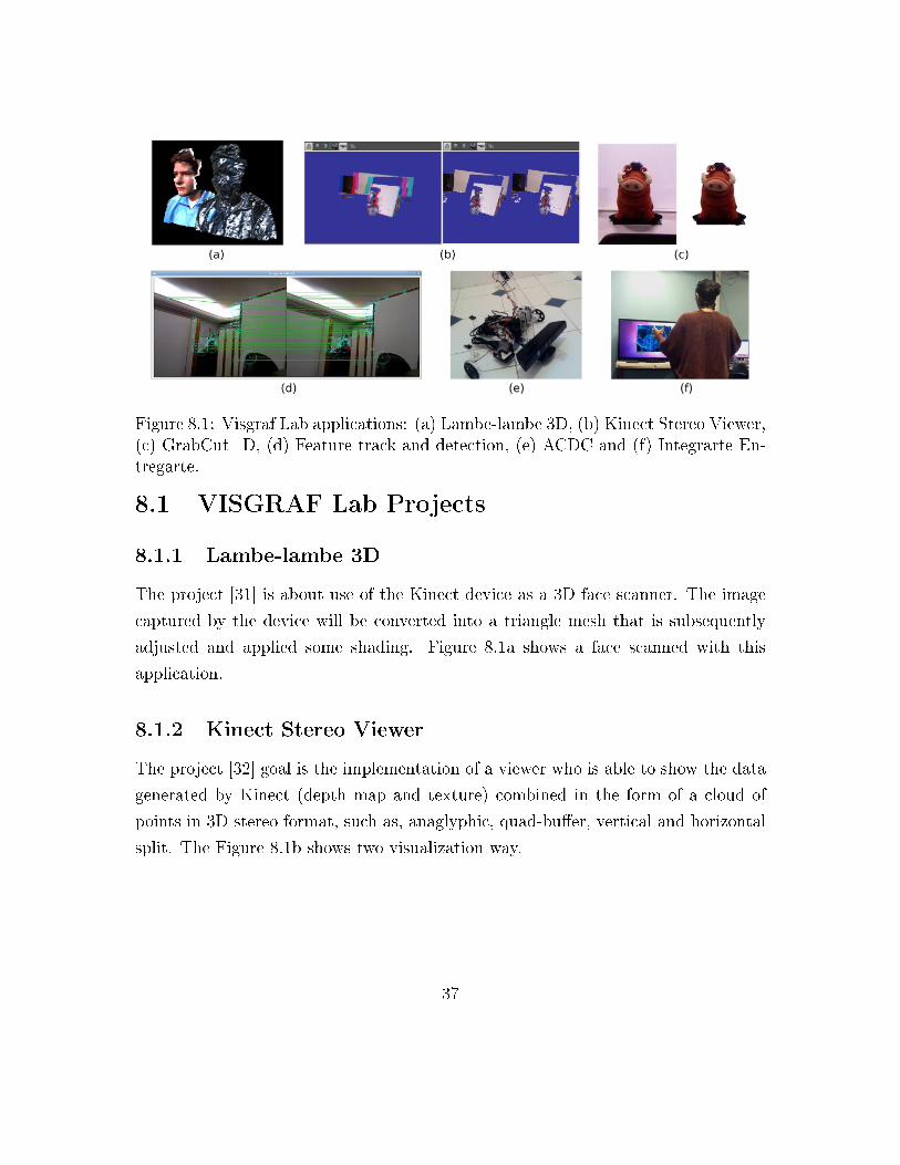
Figure 8.1: Visgraf Lab applications: (a) Lambe-lambe 3D, (b) Kinect Stereo Viewer,(c) GrabCut+D, (d) Feature track and detection, (e) ACDC and (f) Integrarte En-tregarte.
8.1 VISGRAF Lab Projects
8.1.1 Lambe-lambe 3D
The project [31] is about use of the Kinect device as a 3D face scanner. The image
captured by the device will be converted into a triangle mesh that is subsequently
adjusted and applied some shading. Figure 8.1a shows a face scanned with this
application.
8.1.2 Kinect Stereo Viewer
The project [32] goal is the implementation of a viewer who is able to show the data
generated by Kinect (depth map and texture) combined in the form of a cloud of
points in 3D stereo format, such as, anaglyphic, quad-bu�er, vertical and horizontal
split. The Figure 8.1b shows two visualization way.
37
8.1.3 GrabCut+D
This project [28] Prada creates an image segmentation application adding, besides the
RGB data, the depth data to de�ne three Grab-Cut like optimization methods. With
the depth data, the author de�nes some priors that are combined on optimization
problem, in each method. The Figure 8.1c shows an image segmented with this
application.
8.1.4 Feature track and detection: detect and track features
in a RGBD video
The project [33] goal is obtain some features on RGBD images. This features are
de�ned using methods like SIFT and SURF. Before de�ned, the author track this
features along an RGBD Video. The Figure 8.1d shows some features tracked along
two di�erent frames.
8.1.5 ACDC
In this project [34] was developed a robot that can move around a �at �oor using
motorized wheels, and by analyzing the image that provides him a Kinect camera,
can recognize the 3D environment around. This robot provides a mechanic arm that
let him to connect him to power supplies in the wall. To do that it need to analyze
the image from the camera, and recognize these power connectors in the space. The
Figure 8.1e shows the robot created, using Kinect, on this project.
8.1.6 INTEGRARTE ENTREGARTE
This project [35] explores the body and its possible visual and audible outspread.
The person moves were converted in visual shapes and sounds, from di�erent body
relations. The application was implemented with Processing programming language,
and SimpleOpenNI library, which is used to access the data provided by Kinect. The
Figure 8.1 the author using the application.
38
Chapter 9
Conclusion
Along this survey, we introduced the Kinect. This device was developed to be a
control tool to Xbox 360 Console. Besides its original goal (games), nowadays Kinect
is used in industry and research.
This survey was motivated by recently developed research at VISGRAF Lab using
Kinect. It began with an Image Processing course [36] and the projects developed
by students.
In this survey, we discussed the Kinect architecture and sensor. We show that
Kinect provides a depth sensor, an RGB camera, an accelerometer, a motor and
a multiarray of microphones. The captured data is an RGB image and a depth
measurement.
Unfortunately the Kinect depth has some problems like noise and holes. We
presented some �ltering approaches, from the naive solution to the more advanced
�ltering techniques.
There are some tools, such as OpenNI, libfreenect and Microsoft Kinect for Win-
dows that make it easy developing applications for this device in various platforms.
These help the development of many projects based on RGBD Images, besides games.
Despite the fact that Kinect is a device that was only recently launched (Novem-
ber 2010), this data already was used in several areas, such as 3D reconstruction,
robotic, image processing, augmented reality, interaction, object recognition, etc.
Beside these, we can cite its natural application on games (in particular, in the Xbox
39
360 console).
The main reason for the success of this device is the di�erent nature of its data
(visual and geometric). It opens new processing possibilities. The RGBD images
enable to attach old problems with new approaches.
40
Bibliography
[1] �The kinect patent - method and system for object reconstruction,� 2005, http:
//www.wipo.int/patentscope/search/en/WO2007043036.
[2] R. Newcombe, S. Izadi, O. Hilliges, D. Molyneaux, D. Kim, A. Davison, P. Kohli,
J. Shotton, S. Hodges, and A. Fitzgibbon, �Kinectfusion: Real-time dense sur-
face mapping and tracking.� IEEE International Symposium on Mixed and
Augmented Reality, 2011.
[3] B. Curless and M. Levoy, �A volumetric method for building complex models
from range images.� ACM SIGGRAPH, 1996.
[4] C. Hernandez, G. Vogiatzis, and R. Cipolla, �Probabilistic visibility for multi-
view stereo,� in Computer Vision and Pattern Recognition, 2007.
[5] �Nyu depth dataset,� http://cs.nyu.edu/~silberman/datasets/nyu_depth_v2.
html.
[6] �Rgb-d object dataset,� http://www.cs.washington.edu/rgbd-dataset/.
[7] �Cornell-rgbd-dataset,� http://pr.cs.cornell.edu/sceneunderstanding/data/
data.php.
[8] �B3do: Berkeley 3-d object dataset,� http://kinectdata.com/.
[9] �Iros 2011 paper kinect dataset,� http://projects.asl.ethz.ch/datasets/doku.
php?id=kinect:iros2011kinect.
41
[10] A. Janoch, S. Karayev, Y. Jia, J. Barron, M. Fritz, K. Saenko, and T. Darrell,
�A category-level 3-d object dataset: Putting the kinect to work.� ICCV -
WCDCCV, 2011.
[11] N. Silberman and R. Fergus, �Indoor scene segmentation using a structured
light sensor.� International Conference on Computer Vision - Workshop on 3D
Representation and Recognition, 2011.
[12] L. Bo, X. Ren, , and D. Fox, �Unsupervised feature learning for rgb-d based
object recognition.� ISER, 2012.
[13] ��, �Hierarchical matching pursuit for image classi�cation: Architecture and
fast algorithms.� NIPS, 2011.
[14] ��, �Depth kernel descriptors for object recognition.� Proceedings of the
International Conference on Intelligent Robots and Systems, 2011.
[15] L. Bo, K. Lai, X. Ren, , and D. Fox, �Object recognition with hierarchical kernel
descriptors.� Proceedings of the International Conference on Intelligent Robots
and Systems, 2011.
[16] L. Bo, X. Ren, , and D. Fox, �Kernel descriptors for visual recognition.� NIPS,
2010.
[17] K. Lai, L. Bo, X. Ren, , and D. Fox, �Detection-based object labeling in 3d
scenes.� Proceedings of the International Conference on Robotics and Au-
tomation, 2012.
[18] ��, �A scalable tree-based approach for joint object and pose recognition.�
AAAI, 2011.
[19] ��, �Sparse distance learning for object recognition combining rgb and depth
information.� ICRA, 2011.
[20] ��, �A large-scale hierarchical multi-view rgb-d object dataset.� ICRA, 2011.
42
[21] H. S. Koppula, A. Anand, T. Joachims, and A. Saxena, �Semantic labeling of
3d point clouds for indoor scenes.� Proceedings of the Advances in Neural
Information Processing Systems, 2011.
[22] Y. Jiang, M. Stephen, and A. Saxena, �E�cient grasping from rgbd images:
Learning using a new rectangle representation.� ICRA, 2011.
[23] Y. Jiang, M. Lim, C. Zheng, and A. Saxena, �Learning to place new objects in
a scene.� International Journal of Robotics Research, 2012.
[24] S. Izadi, R. Newcombe, D. Kim, O. Hilliges, D. Molyneaux, S. Hodges, P. Kohli,
A. Davison, and A. Fitzgibbon, �Kinectfusion: Real-time dynamic 3d surface
reconstruction and interaction.� ACM SIGGRAPH, 2011.
[25] S. Rusinkiewicz and M. Levoy, �E�cient variants of the icp algorithm.� IEEE
3-D Digital Imaging and Modeling, 2001.
[26] F. Pomerleau, S. Magnenat, F. Colas, M. Liu, and R. Siegwart, �Tracking a
depth camera: Parameter exploration for fast icp.� IEEE Intelligent Robots
and Systems, 2011.
[27] H. Benko, R. Jota, and A. Wilson, �Miragetable: freehand interaction on a
projected augmented reality tabletop.� Conference on Human Factors in Com-
puting Systems, 2012.
[28] F. Prada and L. Velho, �Grabcut+d.� VISGRAF PROJECT, 2011, http://
www.impa.br/~faprada/courses/procImagenes/.
[29] J. Shotton, A. Fitzgibbon, M. Cook, T. Sharp, M. Finocchio, R. Moore, A. Kip-
man, and A. Blake, �Real-time human pose recognition in parts from a single
depth image.� IEEE CVPR, 2011.
[30] L. Spinello and K. Arras, �People detection in rgb-d data.� International Con-
ference on Intelligent Robots and Systems, 2011.
43
[31] D. Lucio and L. Velho, �Lambe-lambe 3d.� VISGRAF PROJECT, 2011, http:
//dlucio.impa.br/wiki/pmwiki.php/Sg3d/Projeto.
[32] ��, �Kinect stereo viewer.� VISGRAF PROJECT, 2011, http://dlucio.impa.
br/wiki/pmwiki.php/ProcessamentoDeImages/Projeto.
[33] F. Benavides and L. Velho, �Feature track and detection: detect and track
features in a rgbd video.� VISGRAF PROJECT, 2011, http://www.impa.br/
~francisc/IProc/report.html.LyXconv/report.html.
[34] J. Lucio and L. Velho, �Acdc.� VISGRAF PROJECT, 2011, http://www.
juliolucio.com/ACDCBot/.
[35] B. Castro and L. Velho, �Integrarte entregarte.� VISGRAF PROJECT, 2011,
http://ctrlbarbara.wordpress.com/category/integrarte-entregarte/.
[36] �Fundamentals and trends in image processing: Rgbd video - 2011,� http://
lvelho.impa.br/ip11/.
44