Embed Size (px)
Citation preview
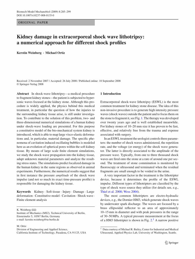
Biomech Model Mechanobiol (2009) 8:285–299DOI 10.1007/s10237-008-0135-0
ORIGINAL PAPER
Kidney damage in extracorporeal shock wave lithotripsy:a numerical approach for different shock profiles
Kerstin Weinberg · Michael Ortiz
Received: 2 November 2007 / Accepted: 26 July 2008 / Published online: 18 September 2008© Springer-Verlag 2008
Abstract In shock-wave lithotripsy—a medical procedureto fragment kidney stones—the patient is subjected to hyper-sonic waves focused at the kidney stone. Although this pro-cedure is widely applied, the physics behind this medicaltreatment, in particular the question of how the injuries tothe surrounding kidney tissue arise, is still under investiga-tion. To contribute to the solution of this problem, two- andthree-dimensional numerical simulations of a human kidneyunder shock-wave loading are presented. For this purposea constitutive model of the bio-mechanical system kidney isintroduced, which is able to map large visco-elastic deforma-tions and, in particular, material damage. The specific phe-nomena of cavitation induced oscillating bubbles is modeledhere as an evolution of spherical pores within the soft kidneytissue. By means of large scale finite element simulations,we study the shock-wave propagation into the kidney tissue,adapt unknown material parameters and analyze the result-ing stress states. The simulations predict localized damage inthe human kidney in the same regions as observed in animalexperiments. Furthermore, the numerical results suggest thatin first instance the pressure amplitude of the shock waveimpulse (and not so much its exact time-pressure profile) isresponsible for damaging the kidney tissue.
Keywords Kidney · Soft tissue · Injury · Damage · Largedeformation · Constitutive model · Cavitation · Shock wave ·Finite element analysis
K. Weinberg (B)Institute of Mechanics (MS2), Technical University of Berlin,Einsteinufer 5, 10587 Berlin, Germanye-mail: [email protected]
M. OrtizDivision of Engineering and Applied Science,California Institute of Technology, Pasadena, CA 91125, USA
1 Introduction
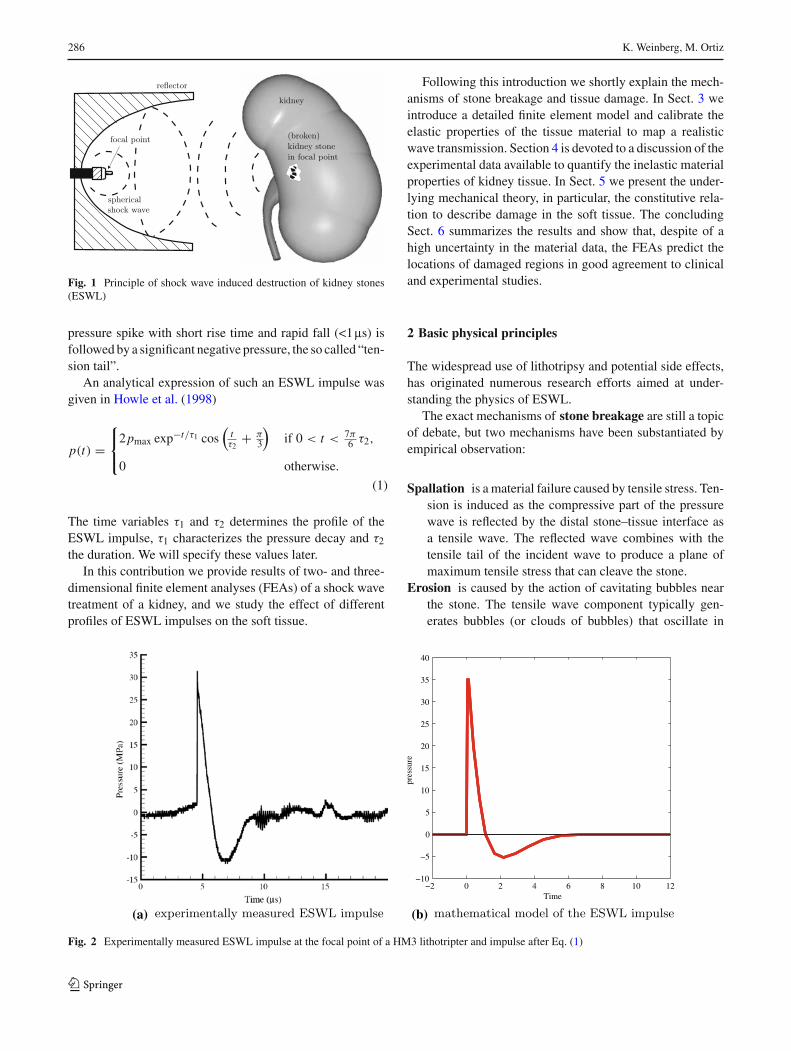
Extracorporeal shock-wave lithotripsy (ESWL) is the mostcommon treatment for kidney stone disease. The idea of thisnon-invasive procedure is to generate high intensity pressurewaves (shock waves) outside the patient and to focus them onthe stone to fragment it, see Fig. 1. The therapy was developedover twenty years ago and is well established meanwhile.For kidney stones of 10–20 mm size it has proven to be fast,effective, and relatively free from the trauma and expenseassociated with surgery.
In an ESWL treatment the urologist controls three parame-ters: the number of shock waves administered, the repetitionrate, and the voltage (or energy) of the shock wave genera-tor. The latter is directly associated to the amplitude of thepressure wave. Typically, from one to three thousand shockwaves are fired onto the stone at a rate of around one per sec-ond. The treatment of stone comminution is monitored byfluoroscopy or ultrasound and terminated when the residualfragments are small enough to be voided in the urine.
A very important factor in the treatment is the lithotripterdevice, because it determines the profile of the ESWLimpulse. Different types of lithotripters are classified by thetype of shock wave source they utilize (for details see, e.g.,Thiel et al. 2000; Wess 2004).
The most common lithotripters are electro-hydraulicdevices, e.g., the Dornier HM3, which generate shock wavesby underwater spark discharge. The waves are focused by abrass ellipsoidal reflector to an area of approximately10–15 mm in diameter and with peak pressures in the rangeof 30–50 MPa. A typical pressure measurement at the focusof a HM3 lithotripter is shown in Fig. 2.1 A narrow positive
1 Data courtesy of Michael R. Bailey, Center for Industrial and MedicalUltrasound, Applied Physics Lab, University of Washington, Seattle.
123
286 K. Weinberg, M. Ortiz
Fig. 1 Principle of shock wave induced destruction of kidney stones(ESWL)
pressure spike with short rise time and rapid fall (<1ms) isfollowed by a significant negative pressure, the so called “ten-sion tail”.
An analytical expression of such an ESWL impulse wasgiven in Howle et al. (1998)
p(t) =⎧⎨
⎩
2pmax exp−t/τ1 cos(
tτ2
+ π3
)if 0 < t < 7π
6 τ2,
0 otherwise.
(1)
The time variables τ1 and τ2 determines the profile of theESWL impulse, τ1 characterizes the pressure decay and τ2
the duration. We will specify these values later.In this contribution we provide results of two- and three-
dimensional finite element analyses (FEAs) of a shock wavetreatment of a kidney, and we study the effect of differentprofiles of ESWL impulses on the soft tissue.
Following this introduction we shortly explain the mech-anisms of stone breakage and tissue damage. In Sect. 3 weintroduce a detailed finite element model and calibrate theelastic properties of the tissue material to map a realisticwave transmission. Section 4 is devoted to a discussion of theexperimental data available to quantify the inelastic materialproperties of kidney tissue. In Sect. 5 we present the under-lying mechanical theory, in particular, the constitutive rela-tion to describe damage in the soft tissue. The concludingSect. 6 summarizes the results and show that, despite of ahigh uncertainty in the material data, the FEAs predict thelocations of damaged regions in good agreement to clinicaland experimental studies.
2 Basic physical principles
The widespread use of lithotripsy and potential side effects,has originated numerous research efforts aimed at under-standing the physics of ESWL.
The exact mechanisms of stone breakage are still a topicof debate, but two mechanisms have been substantiated byempirical observation:
Spallation is a material failure caused by tensile stress. Ten-sion is induced as the compressive part of the pressurewave is reflected by the distal stone–tissue interface asa tensile wave. The reflected wave combines with thetensile tail of the incident wave to produce a plane ofmaximum tensile stress that can cleave the stone.
Erosion is caused by the action of cavitating bubbles nearthe stone. The tensile wave component typically gen-erates bubbles (or clouds of bubbles) that oscillate in
−2 0 2 4 6 8 10 12−10
−5
0
5
10
15
20
25
30
35
40
pres
sure
Time
(b)(a)
Fig. 2 Experimentally measured ESWL impulse at the focal point of a HM3 lithotripter and impulse after Eq. (1)
123
ESWL: a numerical approach 287
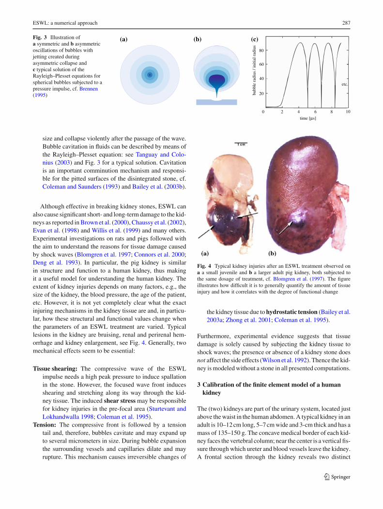
Fig. 3 Illustration ofa symmetric and b asymmetricoscillations of bubbles withjetting created duringasymmetric collapse andc typical solution of theRayleigh–Plesset equations forspherical bubbles subjected to apressure impulse, cf. Brennen(1995)
(c)(a) (b)
time [µs]
bubb
le r
adiu
s / i
nitia
l rad
ius
0 2 4 6 8 10
20
40
60
80
etc.
size and collapse violently after the passage of the wave.Bubble cavitation in fluids can be described by means ofthe Rayleigh–Plesset equation: see Tanguay and Colo-nius (2003) and Fig. 3 for a typical solution. Cavitationis an important comminution mechanism and responsi-ble for the pitted surfaces of the disintegrated stone, cf.Coleman and Saunders (1993) and Bailey et al. (2003b).
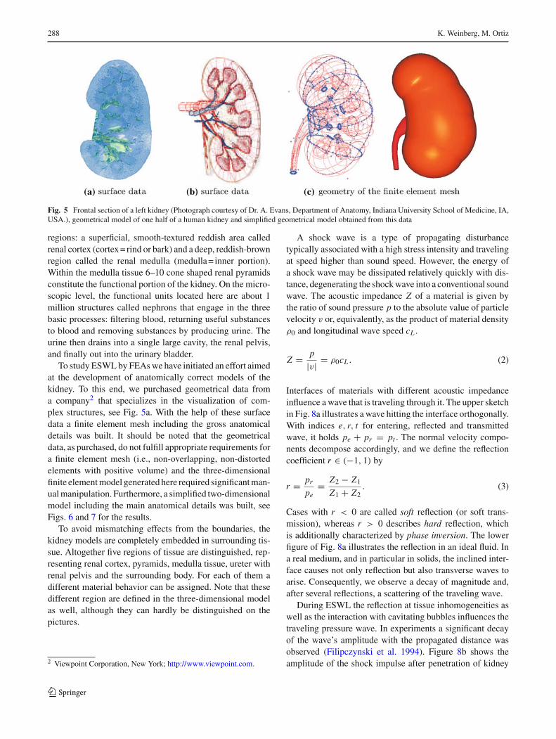
Although effective in breaking kidney stones, ESWL canalso cause significant short- and long-term damage to the kid-neys as reported in Brown et al. (2000), Chaussy et al. (2002),Evan et al. (1998) and Willis et al. (1999) and many others.Experimental investigations on rats and pigs followed withthe aim to understand the reasons for tissue damage causedby shock waves (Blomgren et al. 1997; Connors et al. 2000;Deng et al. 1993). In particular, the pig kidney is similarin structure and function to a human kidney, thus makingit a useful model for understanding the human kidney. Theextent of kidney injuries depends on many factors, e.g., thesize of the kidney, the blood pressure, the age of the patient,etc. However, it is not yet completely clear what the exactinjuring mechanisms in the kidney tissue are and, in particu-lar, how these structural and functional values change whenthe parameters of an ESWL treatment are varied. Typicallesions in the kidney are bruising, renal and perirenal hem-orrhage and kidney enlargement, see Fig. 4. Generally, twomechanical effects seem to be essential:
Tissue shearing: The compressive wave of the ESWLimpulse needs a high peak pressure to induce spallationin the stone. However, the focused wave front inducesshearing and stretching along its way through the kid-ney tissue. The induced shear stress may be responsiblefor kidney injuries in the pre-focal area (Sturtevant andLokhandwalla 1998; Coleman et al. 1995).
Tension: The compressive front is followed by a tensiontail and, therefore, bubbles cavitate and may expand upto several micrometers in size. During bubble expansionthe surrounding vessels and capillaries dilate and mayrupture. This mechanism causes irreversible changes of
Fig. 4 Typical kidney injuries after an ESWL treatment observed ona a small juvenile and b a larger adult pig kidney, both subjected tothe same dosage of treatment, cf. Blomgren et al. (1997). The figureillustrates how difficult it is to generally quantify the amount of tissueinjury and how it correlates with the degree of functional change
the kidney tissue due to hydrostatic tension (Bailey et al.2003a; Zhong et al. 2001; Coleman et al. 1995).
Furthermore, experimental evidence suggests that tissuedamage is solely caused by subjecting the kidney tissue toshock waves; the presence or absence of a kidney stone doesnot affect the side effects (Wilson et al. 1992). Thence the kid-ney is modeled without a stone in all presented computations.
3 Calibration of the finite element model of a humankidney
The (two) kidneys are part of the urinary system, located justabove the waist in the human abdomen. A typical kidney in anadult is 10–12 cm long, 5–7 cm wide and 3-cm thick and has amass of 135–150 g. The concave medical border of each kid-ney faces the vertebral column; near the center is a vertical fis-sure through which ureter and blood vessels leave the kidney.A frontal section through the kidney reveals two distinct
123
288 K. Weinberg, M. Ortiz
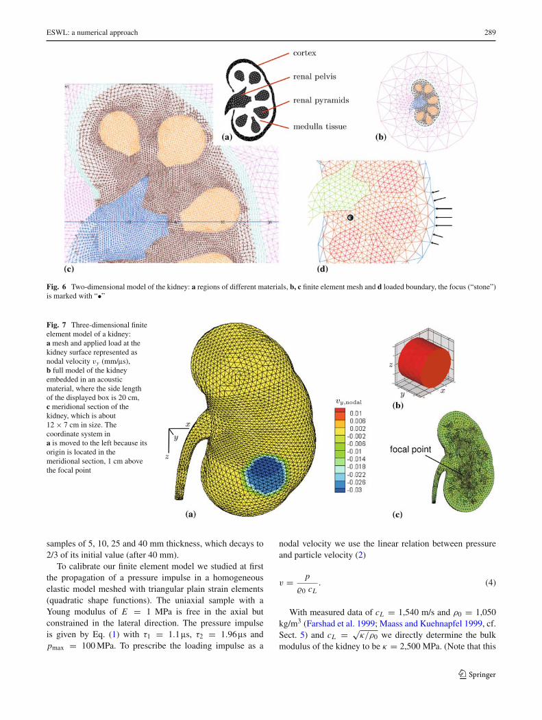
Fig. 5 Frontal section of a left kidney (Photograph courtesy of Dr. A. Evans, Department of Anatomy, Indiana University School of Medicine, IA,USA.), geometrical model of one half of a human kidney and simplified geometrical model obtained from this data
regions: a superficial, smooth-textured reddish area calledrenal cortex (cortex = rind or bark) and a deep, reddish-brownregion called the renal medulla (medulla = inner portion).Within the medulla tissue 6–10 cone shaped renal pyramidsconstitute the functional portion of the kidney. On the micro-scopic level, the functional units located here are about 1million structures called nephrons that engage in the threebasic processes: filtering blood, returning useful substancesto blood and removing substances by producing urine. Theurine then drains into a single large cavity, the renal pelvis,and finally out into the urinary bladder.
To study ESWL by FEAs we have initiated an effort aimedat the development of anatomically correct models of thekidney. To this end, we purchased geometrical data froma company2 that specializes in the visualization of com-plex structures, see Fig. 5a. With the help of these surfacedata a finite element mesh including the gross anatomicaldetails was built. It should be noted that the geometricaldata, as purchased, do not fulfill appropriate requirements fora finite element mesh (i.e., non-overlapping, non-distortedelements with positive volume) and the three-dimensionalfinite element model generated here required significant man-ual manipulation. Furthermore, a simplified two-dimensionalmodel including the main anatomical details was built, seeFigs. 6 and 7 for the results.
To avoid mismatching effects from the boundaries, thekidney models are completely embedded in surrounding tis-sue. Altogether five regions of tissue are distinguished, rep-resenting renal cortex, pyramids, medulla tissue, ureter withrenal pelvis and the surrounding body. For each of them adifferent material behavior can be assigned. Note that thesedifferent region are defined in the three-dimensional modelas well, although they can hardly be distinguished on thepictures.
2 Viewpoint Corporation, New York; http://www.viewpoint.com.
A shock wave is a type of propagating disturbancetypically associated with a high stress intensity and travelingat speed higher than sound speed. However, the energy ofa shock wave may be dissipated relatively quickly with dis-tance, degenerating the shock wave into a conventional soundwave. The acoustic impedance Z of a material is given bythe ratio of sound pressure p to the absolute value of particlevelocity v or, equivalently, as the product of material densityρ0 and longitudinal wave speed cL .
Z = p
|v| = ρ0cL . (2)
Interfaces of materials with different acoustic impedanceinfluence a wave that is traveling through it. The upper sketchin Fig. 8a illustrates a wave hitting the interface orthogonally.With indices e, r, t for entering, reflected and transmittedwave, it holds pe + pr = pt . The normal velocity compo-nents decompose accordingly, and we define the reflectioncoefficient r ∈ (−1, 1) by
r = pr
pe= Z2 − Z1
Z1 + Z2. (3)
Cases with r < 0 are called soft reflection (or soft trans-mission), whereas r > 0 describes hard reflection, whichis additionally characterized by phase inversion. The lowerfigure of Fig. 8a illustrates the reflection in an ideal fluid. Ina real medium, and in particular in solids, the inclined inter-face causes not only reflection but also transverse waves toarise. Consequently, we observe a decay of magnitude and,after several reflections, a scattering of the traveling wave.
During ESWL the reflection at tissue inhomogeneities aswell as the interaction with cavitating bubbles influences thetraveling pressure wave. In experiments a significant decayof the wave’s amplitude with the propagated distance wasobserved (Filipczynski et al. 1994). Figure 8b shows theamplitude of the shock impulse after penetration of kidney
123
ESWL: a numerical approach 289
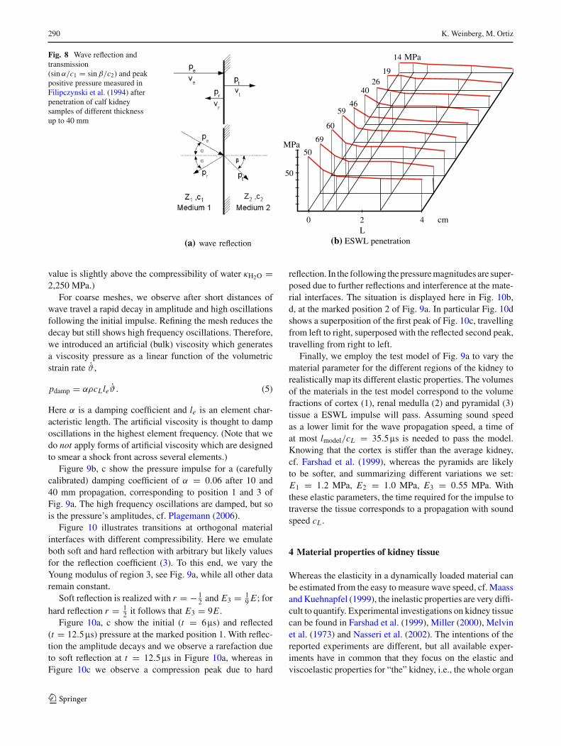
Fig. 6 Two-dimensional model of the kidney: a regions of different materials, b, c finite element mesh and d loaded boundary, the focus (“stone”)is marked with “•”
Fig. 7 Three-dimensional finiteelement model of a kidney:a mesh and applied load at thekidney surface represented asnodal velocity vy (mm/ms),b full model of the kidneyembedded in an acousticmaterial, where the side lengthof the displayed box is 20 cm,c meridional section of thekidney, which is about12 × 7 cm in size. Thecoordinate system ina is moved to the left because itsorigin is located in themeridional section, 1 cm abovethe focal point
samples of 5, 10, 25 and 40 mm thickness, which decays to2/3 of its initial value (after 40 mm).
To calibrate our finite element model we studied at firstthe propagation of a pressure impulse in a homogeneouselastic model meshed with triangular plain strain elements(quadratic shape functions). The uniaxial sample with aYoung modulus of E = 1 MPa is free in the axial butconstrained in the lateral direction. The pressure impulseis given by Eq. (1) with τ1 = 1.1ms, τ2 = 1.96ms andpmax = 100 MPa. To prescribe the loading impulse as a
nodal velocity we use the linear relation between pressureand particle velocity (2)
v = p
�0 cL. (4)
With measured data of cL = 1,540 m/s and ρ0 = 1,050kg/m3 (Farshad et al. 1999; Maass and Kuehnapfel 1999, cf.Sect. 5) and cL = √
κ/ρ0 we directly determine the bulkmodulus of the kidney to be κ = 2,500 MPa. (Note that this
123
290 K. Weinberg, M. Ortiz
Fig. 8 Wave reflection andtransmission(sin α/c1 = sin β/c2) and peakpositive pressure measured inFilipczynski et al. (1994) afterpenetration of calf kidneysamples of different thicknessup to 40 mm
(a) wave reflection
2 40 cm
50
MPa50
69
60
5946
4026
19
14 MPa
L(b) ESWL penetration
value is slightly above the compressibility of water κH2O =2,250 MPa.)
For coarse meshes, we observe after short distances ofwave travel a rapid decay in amplitude and high oscillationsfollowing the initial impulse. Refining the mesh reduces thedecay but still shows high frequency oscillations. Therefore,we introduced an artificial (bulk) viscosity which generatesa viscosity pressure as a linear function of the volumetricstrain rate ϑ ,
pdamp = αρcLleϑ . (5)
Here α is a damping coefficient and le is an element char-acteristic length. The artificial viscosity is thought to damposcillations in the highest element frequency. (Note that wedo not apply forms of artificial viscosity which are designedto smear a shock front across several elements.)
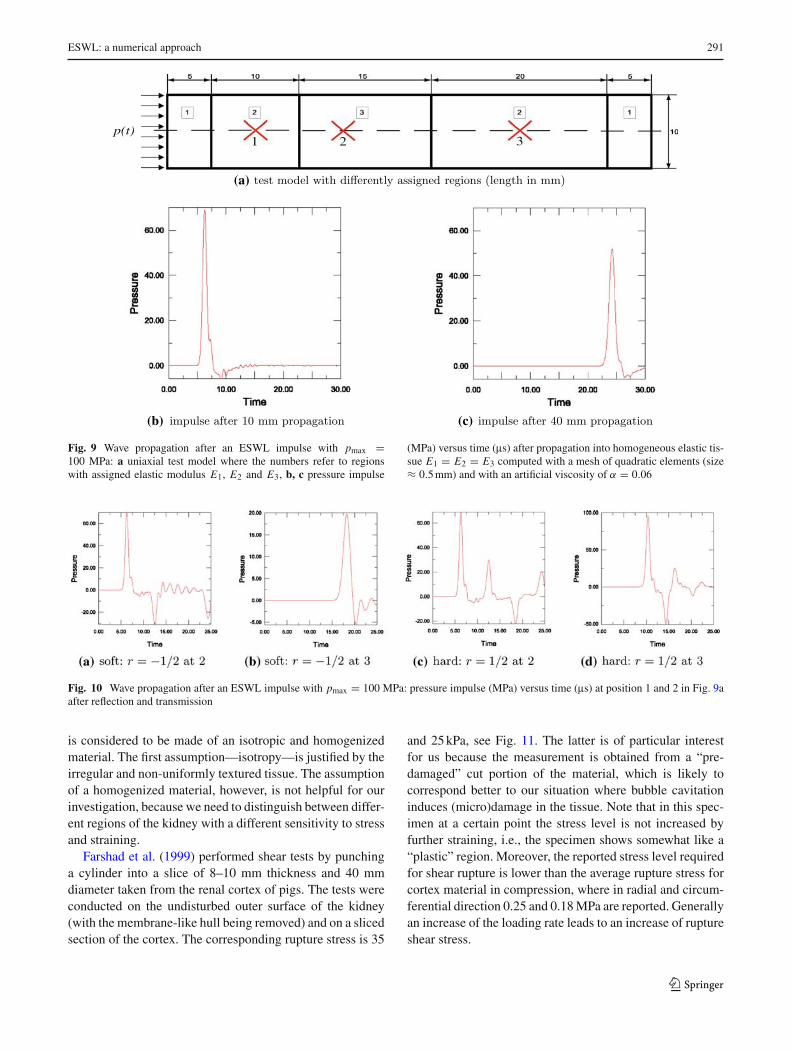
Figure 9b, c show the pressure impulse for a (carefullycalibrated) damping coefficient of α = 0.06 after 10 and40 mm propagation, corresponding to position 1 and 3 ofFig. 9a. The high frequency oscillations are damped, but sois the pressure’s amplitudes, cf. Plagemann (2006).
Figure 10 illustrates transitions at orthogonal materialinterfaces with different compressibility. Here we emulateboth soft and hard reflection with arbitrary but likely valuesfor the reflection coefficient (3). To this end, we vary theYoung modulus of region 3, see Fig. 9a, while all other dataremain constant.
Soft reflection is realized with r = − 12 and E3 = 1
9 E ; forhard reflection r = 1
2 it follows that E3 = 9E .Figure 10a, c show the initial (t = 6ms) and reflected
(t = 12.5ms) pressure at the marked position 1. With reflec-tion the amplitude decays and we observe a rarefaction dueto soft reflection at t = 12.5ms in Figure 10a, whereas inFigure 10c we observe a compression peak due to hard
reflection. In the following the pressure magnitudes are super-posed due to further reflections and interference at the mate-rial interfaces. The situation is displayed here in Fig. 10b,d, at the marked position 2 of Fig. 9a. In particular Fig. 10dshows a superposition of the first peak of Fig. 10c, travellingfrom left to right, superposed with the reflected second peak,travelling from right to left.
Finally, we employ the test model of Fig. 9a to vary thematerial parameter for the different regions of the kidney torealistically map its different elastic properties. The volumesof the materials in the test model correspond to the volumefractions of cortex (1), renal medulla (2) and pyramidal (3)tissue a ESWL impulse will pass. Assuming sound speedas a lower limit for the wave propagation speed, a time ofat most lmodel/cL = 35.5ms is needed to pass the model.Knowing that the cortex is stiffer than the average kidney,cf. Farshad et al. (1999), whereas the pyramids are likelyto be softer, and summarizing different variations we set:E1 = 1.2 MPa, E2 = 1.0 MPa, E3 = 0.55 MPa. Withthese elastic parameters, the time required for the impulse totraverse the tissue corresponds to a propagation with soundspeed cL .
4 Material properties of kidney tissue
Whereas the elasticity in a dynamically loaded material canbe estimated from the easy to measure wave speed, cf. Maassand Kuehnapfel (1999), the inelastic properties are very diffi-cult to quantify. Experimental investigations on kidney tissuecan be found in Farshad et al. (1999), Miller (2000), Melvinet al. (1973) and Nasseri et al. (2002). The intentions of thereported experiments are different, but all available exper-iments have in common that they focus on the elastic andviscoelastic properties for “the” kidney, i.e., the whole organ
123
ESWL: a numerical approach 291
(b) (c)
2 31p(t)
(a)
Fig. 9 Wave propagation after an ESWL impulse with pmax =100 MPa: a uniaxial test model where the numbers refer to regionswith assigned elastic modulus E1, E2 and E3, b, c pressure impulse
(MPa) versus time (ms) after propagation into homogeneous elastic tis-sue E1 = E2 = E3 computed with a mesh of quadratic elements (size≈ 0.5 mm) and with an artificial viscosity of α = 0.06
Fig. 10 Wave propagation after an ESWL impulse with pmax = 100 MPa: pressure impulse (MPa) versus time (ms) at position 1 and 2 in Fig. 9aafter reflection and transmission
is considered to be made of an isotropic and homogenizedmaterial. The first assumption—isotropy—is justified by theirregular and non-uniformly textured tissue. The assumptionof a homogenized material, however, is not helpful for ourinvestigation, because we need to distinguish between differ-ent regions of the kidney with a different sensitivity to stressand straining.
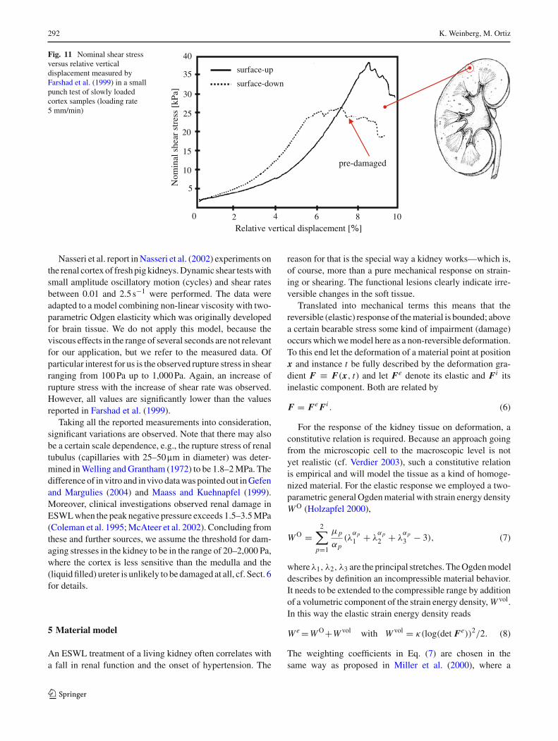
Farshad et al. (1999) performed shear tests by punchinga cylinder into a slice of 8–10 mm thickness and 40 mmdiameter taken from the renal cortex of pigs. The tests wereconducted on the undisturbed outer surface of the kidney(with the membrane-like hull being removed) and on a slicedsection of the cortex. The corresponding rupture stress is 35
and 25 kPa, see Fig. 11. The latter is of particular interestfor us because the measurement is obtained from a “pre-damaged” cut portion of the material, which is likely tocorrespond better to our situation where bubble cavitationinduces (micro)damage in the tissue. Note that in this spec-imen at a certain point the stress level is not increased byfurther straining, i.e., the specimen shows somewhat like a“plastic” region. Moreover, the reported stress level requiredfor shear rupture is lower than the average rupture stress forcortex material in compression, where in radial and circum-ferential direction 0.25 and 0.18 MPa are reported. Generallyan increase of the loading rate leads to an increase of ruptureshear stress.
123
292 K. Weinberg, M. Ortiz
Fig. 11 Nominal shear stressversus relative verticaldisplacement measured byFarshad et al. (1999) in a smallpunch test of slowly loadedcortex samples (loading rate5 mm/min)
surface-up
surface-down
0
5
25
20
15
10
30
40
35
2 4 8 10
Nom
inal
she
ar s
tres
s [k
Pa]
Relative vertical displacement [%]
pre-damaged
6
Nasseri et al. report in Nasseri et al. (2002) experiments onthe renal cortex of fresh pig kidneys. Dynamic shear tests withsmall amplitude oscillatory motion (cycles) and shear ratesbetween 0.01 and 2.5 s−1 were performed. The data wereadapted to a model combining non-linear viscosity with two-parametric Odgen elasticity which was originally developedfor brain tissue. We do not apply this model, because theviscous effects in the range of several seconds are not relevantfor our application, but we refer to the measured data. Ofparticular interest for us is the observed rupture stress in shearranging from 100 Pa up to 1,000 Pa. Again, an increase ofrupture stress with the increase of shear rate was observed.However, all values are significantly lower than the valuesreported in Farshad et al. (1999).
Taking all the reported measurements into consideration,significant variations are observed. Note that there may alsobe a certain scale dependence, e.g., the rupture stress of renaltubulus (capillaries with 25–50mm in diameter) was deter-mined in Welling and Grantham (1972) to be 1.8–2 MPa. Thedifference of in vitro and in vivo data was pointed out in Gefenand Margulies (2004) and Maass and Kuehnapfel (1999).Moreover, clinical investigations observed renal damage inESWL when the peak negative pressure exceeds 1.5–3.5 MPa(Coleman et al. 1995; McAteer et al. 2002). Concluding fromthese and further sources, we assume the threshold for dam-aging stresses in the kidney to be in the range of 20–2,000 Pa,where the cortex is less sensitive than the medulla and the(liquid filled) ureter is unlikely to be damaged at all, cf. Sect. 6for details.
5 Material model
An ESWL treatment of a living kidney often correlates witha fall in renal function and the onset of hypertension. The
reason for that is the special way a kidney works—which is,of course, more than a pure mechanical response on strain-ing or shearing. The functional lesions clearly indicate irre-versible changes in the soft tissue.
Translated into mechanical terms this means that thereversible (elastic) response of the material is bounded; abovea certain bearable stress some kind of impairment (damage)occurs which we model here as a non-reversible deformation.To this end let the deformation of a material point at positionx and instance t be fully described by the deformation gra-dient F ≡ F(x, t) and let Fe denote its elastic and Fi itsinelastic component. Both are related by
F = Fe Fi . (6)
For the response of the kidney tissue on deformation, aconstitutive relation is required. Because an approach goingfrom the microscopic cell to the macroscopic level is notyet realistic (cf. Verdier 2003), such a constitutive relationis empirical and will model the tissue as a kind of homoge-nized material. For the elastic response we employed a two-parametric general Ogden material with strain energy densityW O (Holzapfel 2000),
W O =2∑
p=1
µp
αp(λ
αp1 + λ
αp2 + λ
αp3 − 3), (7)
whereλ1, λ2, λ3 are the principal stretches. The Ogden modeldescribes by definition an incompressible material behavior.It needs to be extended to the compressible range by additionof a volumetric component of the strain energy density, W vol.In this way the elastic strain energy density reads
W e =W O+W vol with W vol = κ(log(det Fe))2/2. (8)
The weighting coefficients in Eq. (7) are chosen in thesame way as proposed in Miller et al. (2000), where a
123
ESWL: a numerical approach 293
a(t)
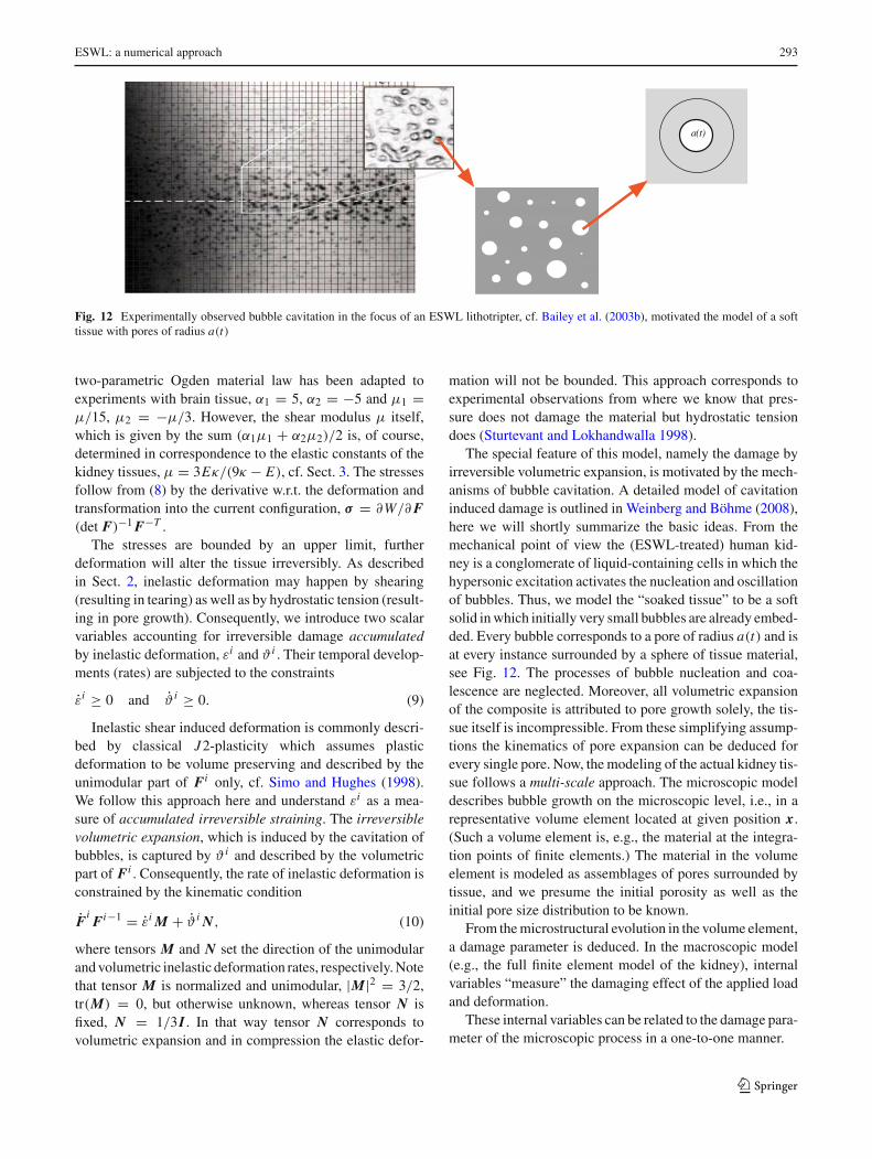
Fig. 12 Experimentally observed bubble cavitation in the focus of an ESWL lithotripter, cf. Bailey et al. (2003b), motivated the model of a softtissue with pores of radius a(t)
two-parametric Ogden material law has been adapted toexperiments with brain tissue, α1 = 5, α2 = −5 and µ1 =µ/15, µ2 = −µ/3. However, the shear modulus µ itself,which is given by the sum (α1µ1 + α2µ2)/2 is, of course,determined in correspondence to the elastic constants of thekidney tissues, µ = 3Eκ/(9κ − E), cf. Sect. 3. The stressesfollow from (8) by the derivative w.r.t. the deformation andtransformation into the current configuration, σ = ∂W/∂ F(det F)−1 F−T .
The stresses are bounded by an upper limit, furtherdeformation will alter the tissue irreversibly. As describedin Sect. 2, inelastic deformation may happen by shearing(resulting in tearing) as well as by hydrostatic tension (result-ing in pore growth). Consequently, we introduce two scalarvariables accounting for irreversible damage accumulatedby inelastic deformation, εi and ϑ i . Their temporal develop-ments (rates) are subjected to the constraints
εi ≥ 0 and ϑ i ≥ 0. (9)
Inelastic shear induced deformation is commonly descri-bed by classical J2-plasticity which assumes plasticdeformation to be volume preserving and described by theunimodular part of Fi only, cf. Simo and Hughes (1998).We follow this approach here and understand εi as a mea-sure of accumulated irreversible straining. The irreversiblevolumetric expansion, which is induced by the cavitation ofbubbles, is captured by ϑ i and described by the volumetricpart of Fi . Consequently, the rate of inelastic deformation isconstrained by the kinematic condition
FiFi−1 = εi M + ϑ i N, (10)
where tensors M and N set the direction of the unimodularand volumetric inelastic deformation rates, respectively. Notethat tensor M is normalized and unimodular, |M|2 = 3/2,tr(M) = 0, but otherwise unknown, whereas tensor N isfixed, N = 1/3I . In that way tensor N corresponds tovolumetric expansion and in compression the elastic defor-
mation will not be bounded. This approach corresponds toexperimental observations from where we know that pres-sure does not damage the material but hydrostatic tensiondoes (Sturtevant and Lokhandwalla 1998).
The special feature of this model, namely the damage byirreversible volumetric expansion, is motivated by the mech-anisms of bubble cavitation. A detailed model of cavitationinduced damage is outlined in Weinberg and Böhme (2008),here we will shortly summarize the basic ideas. From themechanical point of view the (ESWL-treated) human kid-ney is a conglomerate of liquid-containing cells in which thehypersonic excitation activates the nucleation and oscillationof bubbles. Thus, we model the “soaked tissue” to be a softsolid in which initially very small bubbles are already embed-ded. Every bubble corresponds to a pore of radius a(t) and isat every instance surrounded by a sphere of tissue material,see Fig. 12. The processes of bubble nucleation and coa-lescence are neglected. Moreover, all volumetric expansionof the composite is attributed to pore growth solely, the tis-sue itself is incompressible. From these simplifying assump-tions the kinematics of pore expansion can be deduced forevery single pore. Now, the modeling of the actual kidney tis-sue follows a multi-scale approach. The microscopic modeldescribes bubble growth on the microscopic level, i.e., in arepresentative volume element located at given position x.(Such a volume element is, e.g., the material at the integra-tion points of finite elements.) The material in the volumeelement is modeled as assemblages of pores surrounded bytissue, and we presume the initial porosity as well as theinitial pore size distribution to be known.
From the microstructural evolution in the volume element,a damage parameter is deduced. In the macroscopic model(e.g., the full finite element model of the kidney), internalvariables “measure” the damaging effect of the applied loadand deformation.
These internal variables can be related to the damage para-meter of the microscopic process in a one-to-one manner.
123
294 K. Weinberg, M. Ortiz
0 2 4 6 8 10 12 14 16 18 200
0.5
1
1.5
2
2.5
t [µs]
a/a 0
a0 = 0.5 µm
a0 = 1 µm
a0 = 2 µm
loading profile p(t)
0 0.5 1 2 2.50
100
t ns]
pres
sure
[MP
a]
(a) (b)
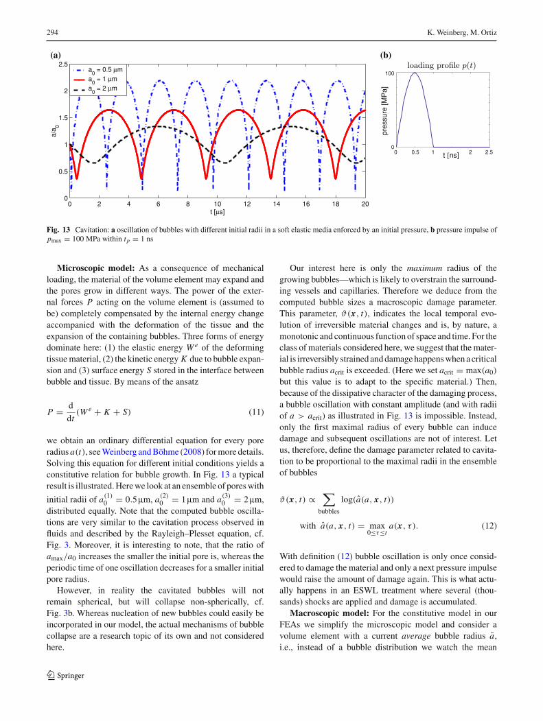
Fig. 13 Cavitation: a oscillation of bubbles with different initial radii in a soft elastic media enforced by an initial pressure, b pressure impulse ofpmax = 100 MPa within tp = 1 ns
Microscopic model: As a consequence of mechanicalloading, the material of the volume element may expand andthe pores grow in different ways. The power of the exter-nal forces P acting on the volume element is (assumed tobe) completely compensated by the internal energy changeaccompanied with the deformation of the tissue and theexpansion of the containing bubbles. Three forms of energydominate here: (1) the elastic energy W e of the deformingtissue material, (2) the kinetic energy K due to bubble expan-sion and (3) surface energy S stored in the interface betweenbubble and tissue. By means of the ansatz
P = d
dt(W e + K + S) (11)
we obtain an ordinary differential equation for every poreradius a(t), see Weinberg and Böhme (2008) for more details.Solving this equation for different initial conditions yields aconstitutive relation for bubble growth. In Fig. 13 a typicalresult is illustrated. Here we look at an ensemble of pores with
initial radii of a(1)0 = 0.5mm, a(2)
0 = 1mm and a(3)0 = 2 mm,
distributed equally. Note that the computed bubble oscilla-tions are very similar to the cavitation process observed influids and described by the Rayleigh–Plesset equation, cf.Fig. 3. Moreover, it is interesting to note, that the ratio ofamax/a0 increases the smaller the initial pore is, whereas theperiodic time of one oscillation decreases for a smaller initialpore radius.
However, in reality the cavitated bubbles will notremain spherical, but will collapse non-spherically, cf.Fig. 3b. Whereas nucleation of new bubbles could easily beincorporated in our model, the actual mechanisms of bubblecollapse are a research topic of its own and not consideredhere.
Our interest here is only the maximum radius of thegrowing bubbles—which is likely to overstrain the surround-ing vessels and capillaries. Therefore we deduce from thecomputed bubble sizes a macroscopic damage parameter.This parameter, ϑ(x, t), indicates the local temporal evo-lution of irreversible material changes and is, by nature, amonotonic and continuous function of space and time. For theclass of materials considered here, we suggest that the mater-ial is irreversibly strained and damage happens when a criticalbubble radius acrit is exceeded. (Here we set acrit = max(a0)
but this value is to adapt to the specific material.) Then,because of the dissipative character of the damaging process,a bubble oscillation with constant amplitude (and with radiiof a > acrit) as illustrated in Fig. 13 is impossible. Instead,only the first maximal radius of every bubble can inducedamage and subsequent oscillations are not of interest. Letus, therefore, define the damage parameter related to cavita-tion to be proportional to the maximal radii in the ensembleof bubbles
ϑ(x, t) ∝∑
bubbles
log(a(a, x, t))
with a(a, x, t) = max0≤τ≤t
a(x, τ ). (12)
With definition (12) bubble oscillation is only once consid-ered to damage the material and only a next pressure impulsewould raise the amount of damage again. This is what actu-ally happens in an ESWL treatment where several (thou-sands) shocks are applied and damage is accumulated.
Macroscopic model: For the constitutive model in ourFEAs we simplify the microscopic model and consider avolume element with a current average bubble radius a,i.e., instead of a bubble distribution we watch the mean
123
ESWL: a numerical approach 295
values.3 An initially undeformed volume of tissue V0 hasafter expansion of bubbles a deformed volume V and thelocal volume fraction of bubbles can be determined as
f = NV0
V
4π a3
3, (13)
where N is the referential bubble density, i.e., the number ofbubbles per unit volume. The volumes V0 and V are relatedthrough V = J V0 where J is the local Jacobian of thedeformation and J e and J i are the corresponding elastic andinelastic components.
J ≡ det F = det(Fe Fi ) = det Fe det Fi ≡ J e J i . (14)
Using these relations, we can express the volume fraction ofbubbles with the inelastic component of the Jacobian
J i = V
J eV0= 1 − f0
1 − f. (15)
Now express with Eq. (13) the initial and maximal volumefraction of bubbles and use the decomposition (14). Then,Eq. (15) may be recast in terms of the maximal averagedbubble radius, ˆa, with the result
J i = 1 − f0 + V
J eV0f = 1 − N
4π a30
3+ N
4π ˆa3
3J e. (16)
It is known that J e ∼= 1 for the (almost) incompressible tissuematerial, and Eq. (16) simplifies to
J i = 1 + 4π
3N ( ˆa3 − a3
0) and
ˆa =[
3
4π
1
N
(J i − 1
)+ a3
0
]1/3
. (17)
Relation (17)2 allows ˆa—which corresponds to the irrever-sible pore size in the tissue—to be computed from J i . Con-sequently, we define in correspondence to (12) but now forthe simplified approach
ϑ i = log(J i ) = log
(
1 + 4π
3N ( ˆa3 − a3
0)
)
(18)
and obtain a clear physical meaning for the internal variableϑ i . It measures the accumulated inelastic volumetric defor-mation.
For implementation of the material model in ourfinite-element code we employ a time-incremental proce-dure similar to the one described in Weinberg et al. (2006)and Weinberg and Ortiz (2005). In every time step tn+1 − tnthe internal state variables, εi
n+1 and ϑ in+1, are updated by
3 Please note that this simplification is only performed to reduce thecomputational effort. In principle the full microscopic model can becomputed at the integration point level. The initial conditions (bubbleradii and size distribution) can change from point to point in the materialand so does its temporal evolution. The restriction to the mean radiusimplies that it grows monotonically to maximal radius ˆa within oneimpulse.
recourse to an incremental objective function fn = fn(Fn+1,
Fen+1, ε
in+1, ϑ
in+1, M, N). This function summarizes the
elastic tissue energy (8), as well as the dissipated energyand the micro-kinetic energy of expanding bubbles. Theseenergetic contributions [subject to the constraints (9 and 10)]compete among themselves, and the optimal internal processis that one which minimizes the function fn .
The result of this energy minimization procedure is thecurrent elastic and inelastic state of the material.
6 Numerical results
With all prerequisites in place we studied the response of thekidney tissue to ESWL shocks by means of several FEAs.The ESWL impulse is distributed along the boundary likea Gaussian distribution, as indicated in Fig. 6 for the two-dimensional model. In the three-dimensional model theimpulse is applied on the anterior kidney surface and focusedin the meridional section at x = 0, y = 0, z = 10 mm, seeFig. 7.
The spatial distribution on the anterior surface is again aGaussian of radius 11 mm (centered at x = 1 mm, y = 0,z = 17 mm). Such a distribution correlates with measureddata of Cleveland et al. (1998) and avoids artificial sheareffects. For reasons of computational capacity not the fullprocess of ESWL but the response of the material to oneimpulse was simulated.
The models are not supported. They are subjected to animpulse of form (1) with pmax = 50 MPa applied as a nodalvelocity via relation (4) and then released. For time integra-tion we employ an explicit Newmark scheme with adaptivetime step size over a period of 100ms.
As described above in the model, regions of functional(sensitive) kidney tissue and non-functional tissue were dis-tinguished. The sensitive structures, i.e., the cortex, the renalpyramids and the surrounding medulla tissue are modeledwith the presented material model, the renal pelvis is pre-sumed to behave elastically. The surrounding body tissue ismodeled as an acoustic material with κ = 2 GPa. Recapit-ulating the reported experimental data, the limiting rupturestress values σ0 were adapted to the different kidney regionsin a similar manner as outlined for the elastic properties inSect. 3. We choose hereσ0 = 2 kPa in the cortex,σ0 = 800 Pain the medulla tissue and σ0 = 25 Pa within the renal pyra-mids and a0 = 1mm, f0 = 0.001 for all parts.
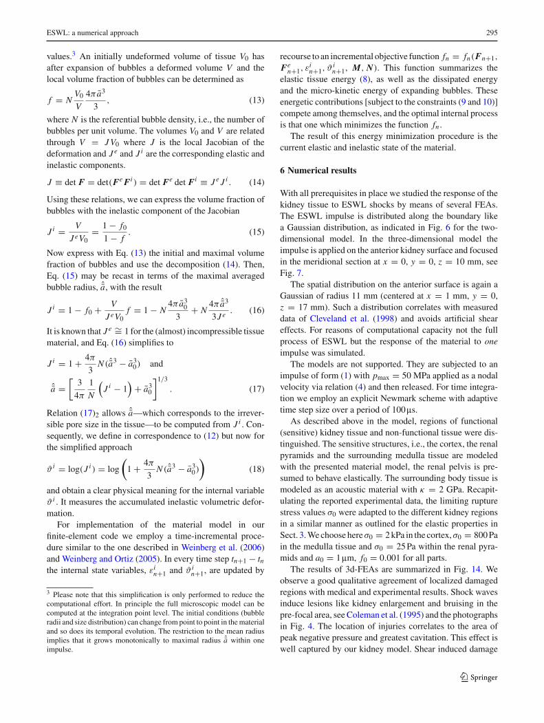
The results of 3d-FEAs are summarized in Fig. 14. Weobserve a good qualitative agreement of localized damagedregions with medical and experimental results. Shock wavesinduce lesions like kidney enlargement and bruising in thepre-focal area, see Coleman et al. (1995) and the photographsin Fig. 4. The location of injuries correlates to the area ofpeak negative pressure and greatest cavitation. This effect iswell captured by our kidney model. Shear induced damage
123
296 K. Weinberg, M. Ortiz
(a) (b)
(c) (d)
Fig. 14 Irreversible straining εi (a, c) and irreversible volumetric expansion ϑ i (b, d) computed in the three-dimensional model of the kidney. Theupper pictures (a, b) show the outside, the lower pictures (c, d) show the meridional section of the kidney
is observed in our model only within the kidney and hardlyin the renal cortex, see Fig. 14.
To our knowledge there is no way to determine if the dam-age on the surface of the actual kidney is due to shear orvolume expansion. But if the pressure is distributed like aGaussian (what is measured, e.g., in Cleveland et al. 1998),
shearing should be of minor influence. However, it wouldplay a role if the kidney surface is hit with a beam-like pres-sure impulse. In this case, the effect can be seen in compu-tational simulations as well.
Furthermore, medical studies do not provide enough infor-mation to meter the degree of tissue damage. Typically such
123
ESWL: a numerical approach 297
studies correlate, e.g., the size of the kidney, the age of thepatient or other parameters to the observed fall in renal func-tion after an ESWL treatment. The exact location of theimpulse hitting the kidney surface and further mechanicaldetails of the treatment are usually not reported. Thereforeit is hardly possible to quantify the tissue damage from themechanical point of view.
Summarizing we can state that the highest damage occursat the focus of the ESWL impulse. This is the position wheretypically the stone is located. In general, the presence ofthe stone, which is neglected here, will alter the pressurefield of the surrounding tissue through reflection of the inci-dent shock wave. Such reflection may even enhance tissuedamage. On the other hand, experimental studies reported inCleveland et al. (1998) did not find a significant influence of(the presence or absence of) a stone on the observed injuriescaused by an ESWL treatment.
Because a quantitative assessment of the results is diffi-cult to give we need to emphasize that the values computedfor ϑ i , εi and displayed in Fig. 14 actually should be scaledwith (yet unknown) reference values of ’completely dam-aged tissue’. Moreover, after all we know the applied elasticmaterial parameter can considered to be an upper bound ofthe materials elasticity in a rapid loading regime. This may,in part, overestimate the stresses (and the resulting damage)in our model. On the other hand, in that way a significanteffect of one shock is visible. In practise, there are severalhundred shocks applied and the damage within the kidneyaccumulates.
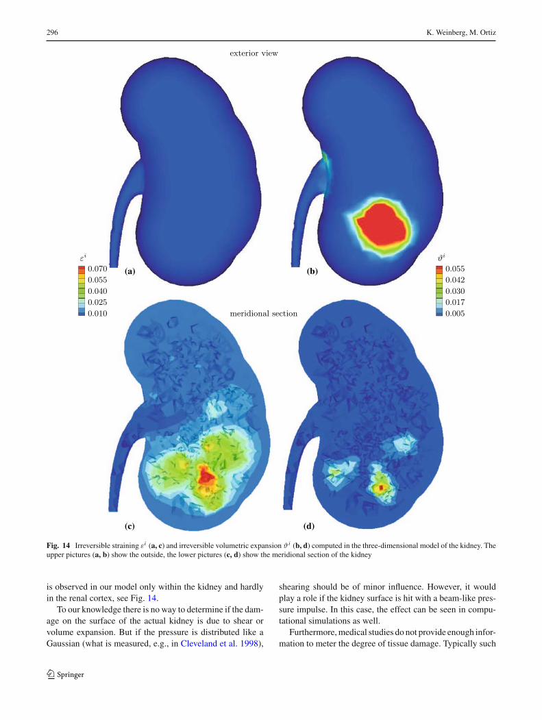
In an attempt to see the influence of the lithotripter device,we varied the (temporal) profile of ESWL impulse, p(t).The original ESWL impulse as displayed in Fig. 2 is namedChurch impulse and is described by Eq. (1) with specifiedvalues of τ1 = 1.1ms and τ2 = 1.96ms. Bailey (2002)and Matula et al. (2002) concluded from experimental
observations of an HM3 lithotripter that the actual impulsearriving at the focal point (in water) is somewhat stretchedand better described by τ1 = 1.96ms and τ2 = 3.57ms. Com-paring the energy per area transported with a ESWL impulse(Wess 2004),
W
A= 1
ρcL
∫
ttotal
p(t)dt (19)
shows that the energy of a Bailey impulse is about 80% higherthan the energy of the Church impulse. A possible conse-quence may be a more pronounced damage in the kidneytissue. For reason of comparison, we also apply to our modelan energy equivalent Church impulse, i.e., an impulse withsame energy transport as the Bailey impulse and τ1 = 1.1ms,τ2 = 1.96ms. The amplitude is then 90.9 MPa, see Fig. 15a.
The three different ESWL impulses were applied to afine two-dimensional mesh with material data as above andviscosity parameter α = 0.06. The cavitation induced irre-versible volumetric expansion ϑ(i) (damage) is displayed inFig. 15b. It is induced here by the Bailey impulse, but its dis-tribution is representative for all three ESWL impulses. Forcomparison the damage is quantified for two different initialbubbles sizes, Fig. 15c, the displayed values are scaled withthe computed maximum, therefor. Note that the influence ofthe bubble radius in our model enters the result by the def-inition of a critical bubble radius for initiating damage, cf.Eq. (16).
The highest damage is observed for the energy equiva-lent Church impulse, whereas the differences of Church andBailey impulse with same amplitude are small. This effectis very likely due to the greater tensile stress caused bythe tail of the higher impulse. The initial compressive frontdoes not directly cause damage but a higher tension wouldcause more cavitation, i.e., bubbles expand to a larger size.
0 2 4 6 8 10 12−20
0
20
40
60
80
100
pres
sure
[MP
a]
time [µs]
Bailey impulseChurch impulseenergy equivalent Church impulse
1 2 3
1
dam
age
initial bubbles 1 µminitial bubbles 2 µm
0
(a) (b) (c)
Fig. 15 Variation of the ESWL profile: a different shapes of ESWLimpulse, b damage induced by a Bailey impulse in the 2d model andc comparison of the damaging effect of different wave profiles for two
initial bubble sizes (1: Bailey impulse, 2: amplitude equivalent Churchimpulse, 3: energy equivalent Church impulse)
123

298 K. Weinberg, M. Ortiz
-50
50
time [µs]
-50 -50
0 0
50 50
0
0 4020 0 4020 0 4020
pres
sure
[M
Pa]
time [µs] time [µs]
(a) (b) (c) (d)
Fig. 16 Pressure state resulting from different ESWL impulses: a location of the measured impulse (red: compression, blue: tension), b Baileyimpulse of 50 MPa amplitude, c amplitude equivalent Church impulse, d energy equivalent Church impulse
This implication is known from studies on bubble dynamics,which have shown that the amplitude of the tensile portion ofthe shock impulse is the major contributor to bubble growth,cf. Iloreta et al. (2007).
The exact details of the lithotripter waveform seems notto be as important for inducing volumetric expansion as themaximum value of pressure (and thus tension) of the ESWLimpulse. To underline this result the actual magnitude of pres-sure arriving at the location of maximal damage is displayedin Fig. 16. It appeared that the decay of pressure amplitudein part correlates with the experimental data of Filipczyn-ski et al. (1994). After about 40 mm of transmission thepressure maxima are 70% of the initial amplitude for theBailey impulse and 50% for the amplitude equivalent Churchimpulse.
Moreover, a significantly enlarged tension tail is observedfor both Church impulses. However, the energy of the impulsedoes not determine the damage but rather the magnitude ofthe tensile or compressive stresses. This will be the reason forthe observation that an amplitude equivalent Church impulseinduces almost the same volumetric damage as the longerBailey impulse.
7 Conclusions
Summarizing we state that the presented numerical analy-sis of ESWL is a powerful tool for studying the effect ofshock waves on soft tissue. The underlying material modeldescribes the macroscopic constitutive behavior with a micro-scopic approach. With a detailed finite-element model ofthe kidney that maps the various structures individually andaccounts for inelastic strain, cavitation and volume expansionwe are able to predict the onset of damage in the kidney tissue.The damaged regions located by our model are in the focaland pre-focal area of the shock wave. These results compare
well with medical and experimental findings. In particular,we are able to analyze the influence of form and energy of theESWL impulse on the tissue. Our findings suggest that not theinitial compressive pressure front of the shock wave inducestissue damage but rather the greater tensile stress caused bythe tail of the impulse. Therefore, comparing two ESWLimpulses with same energy transport the one with largertensile amplitude is more destructive. Moreover, a bubbledistribution with initially large bubbles magnifies the dam-aging effect of cavitation.
A significant refinement of the finite element modelstogether with a variation of the initial conditions of strain-ing and bubble cavitation will further improve the qualityof the computational results. However, a simulation of afull ESWL process with several hundred shocks is limitedby computational capacity. Nonetheless, our novel compu-tational approach provides an efficient strategy to asses sideeffects of shock-wave lithotripsy treatments.
Acknowledgments The work was in part founded by the NIH grant#DK55674. The authors gratefully acknowledge the support.
References
Bailey M (2002) Presentation at the meeting of the consortium for shockwaves in medicine (unpublished), Indianapolis, IA
Bailey MR, Cleveland RO, Colonius T, Crum LA, Evan AP, Lingeman J,McAteer JA, Sapozhnikov OA, Williams JC (2003a) Cavitation inshock wave lithotripsy: the critical role of bubble activity in stonebreakage and kidney trauma. In: Proceedings of IEEE UltrasonicsSymposium, pp 724–727
Bailey M, Crum L, Sapozhnikov O, Evan A, McAteer J, Cleveland R,Colonius T (2003b) Cavitation in shock wave lithotripsy.In: Proceedings of the 5th International Symposium on Cavita-tion, Osaka, Japan
Blomgren PM, Connors BA, Lingeman JE, Willis LR, Evan AP (1997)Quantitation of shock wave lithotripsy-induced lesion in small andlarge pig kidneys. Anat Rec 249(3):341–348
123
ESWL: a numerical approach 299
Brennen CE (1995) Cavitation and bubble dynamics (Oxford Engineer-ing Science Series). Oxford University Press, New York
Brown SA, Munver R, Delvecchio FC, Kuo RL, Zhong P, PremingerGM (2000) Microdialysis assessment of shock wave lithotripsy-induced renal injury. Urology 56(3):364–368
Chaussy C, Schmiedt E, Jocham D, Brendel W, Forssmann B, Walther V(2002) First clinical experience with extracorporeally induceddestruction of kidney stones by shock waves (reprinted from JUrol 127:417–420, 1981). J Urol 167(5):1957–1960
Cleveland RO, Lifshitz DA, Connors BA, Evan AP, Willis LR, Crum LA(1998) In vivo pressure measurements of lithotripsy shock wavesin pigs. Ultrasound Med Biol 24(2):293–306
Coleman A, Saunders J (1993) A review of the physical-properties andbiological effects of the high amplitude acoustic fields used inextracorporeal lithotripsy. Ultrasonics 31:75–89
Coleman AJ, Kodama T, Choi MJ, Adams T, Saunders JE (1995) Thecavitation threshold of human tissue exposed to 0.2-mhz pulsedultrasound—preliminary measurements based on a study of clini-cal lithotripsy. Ultrasound Med Biol 21(3):405–417
Connors BA, Evan AP, Willis LR, Blomgren PM, Lingeman JE,Fineberg NS (2000) The effect of discharge voltage on renal injuryand impairment caused by lithotripsy in the pig. J Am Soc Nephrol11:310–318
Deng YL, Luo DZ, Chen HG (1993) Effects of high-energy shock-waves on testes of wistar rats. J Endourol 7(5):383–386
Evan AP, Willis LR, Lingeman JE, McAteer JA (1998) Renal traumaand the risk of long-term complications in shock wave lithotripsy.Nephron 78(1):1–8
Farshad M, Barbezat M, Flueler P, Schmidlin F, Graber P, Niederer P(1999) Material characterization of the pig kidney in relation withthe biomechanical analysis of renal trauma. J Biomech 32(4):417–425
Filipczynski L, Etienne J, Kujawska T (1994) Shock-wave pulse pres-sure after penetration of kidney tissue. IEEE Trans UltrasonFerroelectr Freq Control 41(1):130–133
Gefen A, Margulies SS (2004) Are in vivo and in situ brain tissuesmechanically similar?. J Biomech 37:1339–1352
Holzapfel G (2000) Nonlinear solid mechanics. Wiley, New YorkHowle L, Schaefer DG, Shearer M, Zhong P (1998) Lithotripsy: the
treatment of kidney stones with shock waves. SIAM 40:356–371Iloreta IJ, Zhou Y, Sankin GN, Zhong P, Szeri AJ (2007) Assessment
of shock wave lithotripters via cavitation potential. Phys Fluids19(8):086103
Maass H, Kuehnapfel U (1999) Noninvasive measurement of elasticproperties of living tissue. Institut für Angewandte Informatik,Forschungszentrum Karlsruhe
Matula T, Hilmo P, Storey B, Szeri A (2002) Radial response of indi-vidual bubbles subjected to shock wave lithotripsy pulses in vitro.Phys Fluids 14(3):913–921
McAteer J, Williams J, Willis L, Evans AE (2002) Personal communica-tion with the autor (k.w.) at the SWL group meeting, Indianapolis,IA
Melvin JW, Stalnaker RL, Roberts VL (1973) Impact injurymechanisms in abdominal organs. SAE Trans (cited in Miller2000) 700968:115–126
Miller K (2000) Constitutive modelling of abdominal organs. J Bio-mech 33:367–376
Miller K, Chinzei K, Orssengo G, Bednarz P (2000) Mechanical prop-erties of brain tissue in-vivo: experiment and computer simulation.J Biomech 33:1369–1376
Nasseri S, Bilston LE, Phan-Thien N (2002) Viscoelastic properties ofpig kidney in shear, experimental results and modelling. RheolActa 41:180–192
Plagemann M (2006) Numerische Untersuchungen zur Belastung dermenschlichen Niere während einer Lithotripsie-Behandlung.Studienarbeit, Institut für Mechanik, TU Berlin
Schmidlin FR, Schmid P, Kutyka T, Iselin C, Graber P (1996) Forcetransmission and stress distribution in a computer simulated modelof a kidney: An analysis of the injury mechanisms in renal trauma.J Trauma 40:791–796
Simo JC, Hughes TJR (1998) Computational inelasticity. Springer,Berlin
Sturtevant B, Lokhandwalla M (1998) Biomechanical effects of ESWLshock waves. J Acoust Soc Am 103:3037–3053
Tanguay M, Colonius T (2003) Progress in modeling and simulation ofshock wave lithotripsy (SWL). In: Proceedings of the 5th Interna-tional Symposium on Cavitation, Osaka, Japan, published elec-tronically at http://iridium.me.es.osaka-u.ac.jp/cav2003/index1.html:paperOS-2-1-010
Thiel M, Nieswand M, Dorffel M (2000) The use of shock waves inmedicine—a tool of the modern or: an overview of basic physi-cal principles, history and research. Minim Invasive Ther AlliedTechnol 9(3–4):247–253
Verdier C (2003) Rheological properties of living materials. From cellsto tissues. J Theor Med 5:67–91
Weinberg K, Böhme T (2008) Mesoscopic modeling for continuawith pores: biological soft tissue. Non-equilibrium Thermodyn33(1):1–25
Weinberg K, Ortiz M (2005) Shock wave induced damage in kidneytissue. Comput Mater Sci 32:588–593
Weinberg K, Mota A, Ortiz M (2006) A variational constitutive modelfor porous metal plasticity. Comput Mech 37(2):142–152
Welling LW, Grantham JJ (1972) Physical properties of isolated per-fused renal tubules and tubular basement membranes. J Clin Invest51:1063–1075
Wess O (2004) Physikalische Grundlagen der Stoßwellentherapie.J Mineralstoffwechsel 4:7–18
Willis LR, Evan AP, Connors BA, Blomgren P, Fineberg NS, LingemanJE (1999) Relationship between kidney size, renal injury, and renalimpairment induced by SWL. J Am Soc Nephrol 10:1753–1762
Wilson WT, Morris JS, Husmann DA, Preminger GM (1992)Extracorporeal shock-wave lithotripsy—comparison betweenstone and no-stone animal-models of SWL. J Endourol 6(1):33–36
Zhong P, Zhou Y, Zhu S (2001) Dynamics of bubble oscillation inconstrained media and mechanisms of vessel rupture in SWL.Ultrasound Med Biol 27:119–134
123