Embed Size (px)
Citation preview
KI evaluation by the displacement extrapolation technique
Gustavo V. Guinea*, Jaime Planas, Manuel Elices
Departamento de Ciencia de Materiales, Universidad PoliteÂcnica de Madrid, E.T.S.I. Caminos Universitaria s/n, 28040-Madrid, Spain
Received 8 October 1999; received in revised form 1 February 2000; accepted 1 February 2000
Abstract
This paper shows the in¯uence of element size, element shape, and mesh arrangement on numerical values of KI
obtained by the displacement method, and gives some guidelines to obtain KI values as good as the most accurateenergy based estimations, typically within a few percent di�erence of the exact value. Three di�erent displacement-
based extrapolation techniques are analyzed. The in¯uence of stress state is also shown. 7 2000 Elsevier ScienceLtd. All rights reserved.
Keywords: Stress intensity factor; Finite elements; Displacement extrapolation techniques
1. Introduction
The evaluation of stress intensity factors in 2D geometries by means of the ®nite element method is a
technique widely used for non standard crack con®gurations. Basically, there are two groups of
estimation methods, those based on ®eld extrapolation near the crack tip [1,2] and those which make
use of the energy release when the crack propagates. This latter group includes the J-contour
integration, the elemental crack extension, the sti�ness derivative method [3] and the recent energy
domain integral formulation [4,5]. All require special post-processing routines, and it is often very
di�cult, if not impossible, to separate KI and KII components in mixed mode problems. Their main
advantage is that relatively coarse meshes can give accurate estimations for the stress intensity factor.
In contrast, methods based on near-tip ®eld ®tting procedures require ®ner meshes to produce a good
numerical representation of crack-tip ®elds, the most accurate methods being those based on nodal
displacements, which are a primary output of the ®nite element program. To represent adequately the
singular strain ®eld near the crack tip, a modi®ed isoparametric element is introduced, as suggested by
Engineering Fracture Mechanics 66 (2000) 243±255
0013-7944/00/$ - see front matter 7 2000 Elsevier Science Ltd. All rights reserved.
PII: S0013-7944(00 )00016-3
www.elsevier.com/locate/engfracmech
* Corresponding author. Tel.: +34-91-336-66-79; fax: +34-91-336-66-80.
E-mail address: [email protected] (G.V. Guinea).
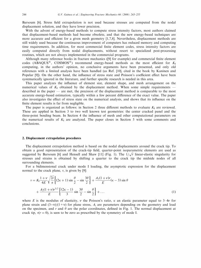
Barsoum [6]. Stress ®eld extrapolation is not used because stresses are computed from the nodaldisplacement solution, and they have lower precision.
With the advent of energy-based methods to compute stress intensity factors, most authors claimedthat displacement-based methods had become obsolete, and that the new energy-based techniques aremore accurate and e�cient for a given mesh geometry [1,7,8]. Nevertheless, displacement methods arestill widely used because the continuous improvement of computers has reduced memory and computingtime requirements. In addition, for most commercial ®nite element codes, stress intensity factors areeasily computed directly from nodal displacements, without resort to specialized post-processingroutines, which are not always implemented in the commercial programs.
Although many reference books in fracture mechanics ([9] for example) and commercial ®nite elementcodes (ABAQUS1, COSMOS1) recommend energy-based methods as the most e�cient for KI
computing, in the authors' opinion, no conclusive arguments have been presented, and only oldreferences with a limited analysis have been handled (as Ref. [10], cited in the book by Kaninen andPopelar [9]). On the other hand, the in¯uence of stress state and Poisson's coe�cient e�ect have beensystematically ignored in the literature, and further speci®c research is needed in this area.
This paper analyzes the in¯uence of element size, element shape, and mesh arrangement on thenumerical values of KI obtained by the displacement method. When some simple requirements Ðdescribed in the paper Ð are met, the precision of the displacement method is comparable to the mostaccurate energy-based estimation, typically within a few percent di�erence of the exact value. The paperalso investigates the e�ect of stress state on the numerical analysis, and shows that its in¯uence on the®nite element results is far from negligible.
The paper is organized as follows: in Section 2 three di�erent methods to evaluate KI are reviewed.These are applied in Section 3 to two well known test geometries: the center cracked panel and thethree-point bending beam. In Section 4 the in¯uence of mesh and other computational parameters onthe numerical results of KI are analyzed. The paper closes in Section 5 with some comments andconclusions.
2. Displacement extrapolation procedures
The displacement extrapolation method is based on the nodal displacements around the crack tip. Toobtain a good representation of the crack-tip ®eld, quarter-point isoparametric elements are used assuggested by Barsoum [6] and Hensell and Shaw [11] (Fig. 1). The 1=
��rp
linear-elastic singularity forstresses and strains is obtained by shifting a quarter to the crack tip the midside nodes of allsurrounding elements.
For a bidimensional crack under mode I loading, the asymptotic expression for the displacementnormal to the crack plane, v, is given by [9]:
v � KI1� n4E
������2r
p
r ��2k� 1� sin
y2ÿ sin
3y2
�� A1�1� n�r
E�kÿ 3� sin y
� A2�1� n�r3=2E
� �2kÿ 1�3
sin3y2ÿ sin
y2
�� . . . �1�
where E is the modulus of elasticity, n the Poisson's ratio, k an elastic parameter equal to 3±4n forplane strain and (3ÿn)/(1+n) for plane stress, Ai are parameters depending on the geometry and loadon the specimen, and r and y are the polar coordinates, de®ned in Fig. 1. The normal displacement atcrack tip, v�r � 0�, is seen to be zero as prescribed by the symmetry of mode I.
G.V. Guinea et al. / Engineering Fracture Mechanics 66 (2000) 243±255244
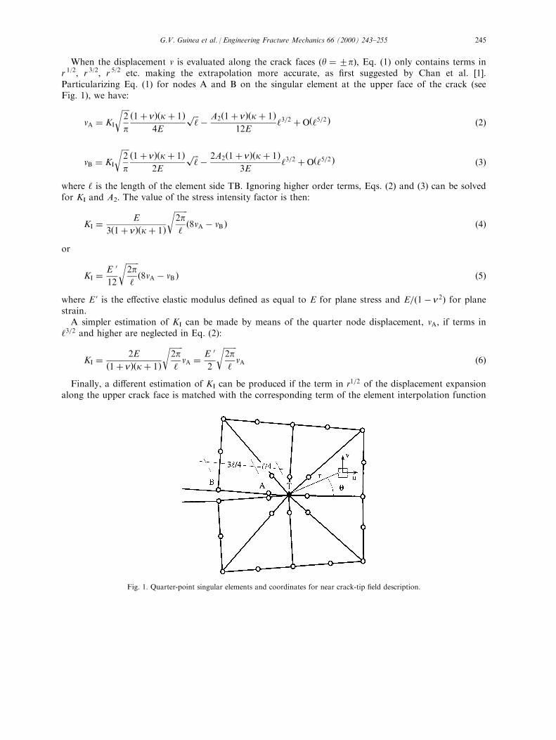
When the displacement v is evaluated along the crack faces �y �2p), Eq. (1) only contains terms inr 1/2, r 3/2, r 5/2 etc. making the extrapolation more accurate, as ®rst suggested by Chan et al. [1].Particularizing Eq. (1) for nodes A and B on the singular element at the upper face of the crack (seeFig. 1), we have:
vA � KI
����2
p
r �1� n��k� 1�4E
���̀pÿ A2�1� n��k� 1�
12E`3=2 � O�`5=2� �2�
vB � KI
����2
p
r �1� n��k� 1�2E
���̀pÿ 2A2�1� n��k� 1�
3E`3=2 � O�`5=2 � �3�
where ` is the length of the element side TB. Ignoring higher order terms, Eqs. (2) and (3) can be solvedfor KI and A2. The value of the stress intensity factor is then:
KI � E
3�1� n��k� 1�
�������2p`
r�8vA ÿ vB � �4�
or
KI � E 0
12
�������2p`
r�8vA ÿ vB � �5�
where E ' is the e�ective elastic modulus de®ned as equal to E for plane stress and E=�1ÿ n2� for planestrain.
A simpler estimation of KI can be made by means of the quarter node displacement, vA, if terms in`3=2 and higher are neglected in Eq. (2):
KI � 2E
�1� n��k� 1�
�������2p`
rvA � E 0
2
�������2p`
rvA �6�
Finally, a di�erent estimation of KI can be produced if the term in r1=2 of the displacement expansionalong the upper crack face is matched with the corresponding term of the element interpolation function
Fig. 1. Quarter-point singular elements and coordinates for near crack-tip ®eld description.
G.V. Guinea et al. / Engineering Fracture Mechanics 66 (2000) 243±255 245
for v�r�: The displacement ®eld along the crack edge y � p for a singular eight-node or six-nodeisoparametric element is a function of the nodal displacements vA and vB, and is given by (see Fig. 1):
v�r� � �4vA ÿ vB �����r
`
rÿ �4vA ÿ 2vB � r
`�7�
By setting y � p in Eq. (1) and identifying terms with��rp
in Eqs. (1) and (7) we obtain:
KI �����2
p
r �1� n��k� 1�2E
��rp � �4vA ÿ vB �
����r
`
r�8�
and the stress intensity factor is now:
KI � E
�1� n��k� 1�
�������2p`
r�4vA ÿ vB � � E 0
4
�������2p`
r�4vA ÿ vB � �9�
Eqs. (5), (6) and (9) are three di�erent estimates of KI based on the nodal displacements of the quarter-point element located on the upper face of the crack. Due to symmetry, a similar result would beobtained for the lower face element. In the following section we evaluate the performance of these threeKI estimates.
3. Numerical analysis
The three procedures for evaluating KI reviewed in Section 2 are now applied to two well knowngeometries: the center cracked plate and the three-point bending beam. The in¯uence of the number andsize of the elements, of the stress state and Poisson's ratio are analyzed for each case.
3.1. Center cracked plate
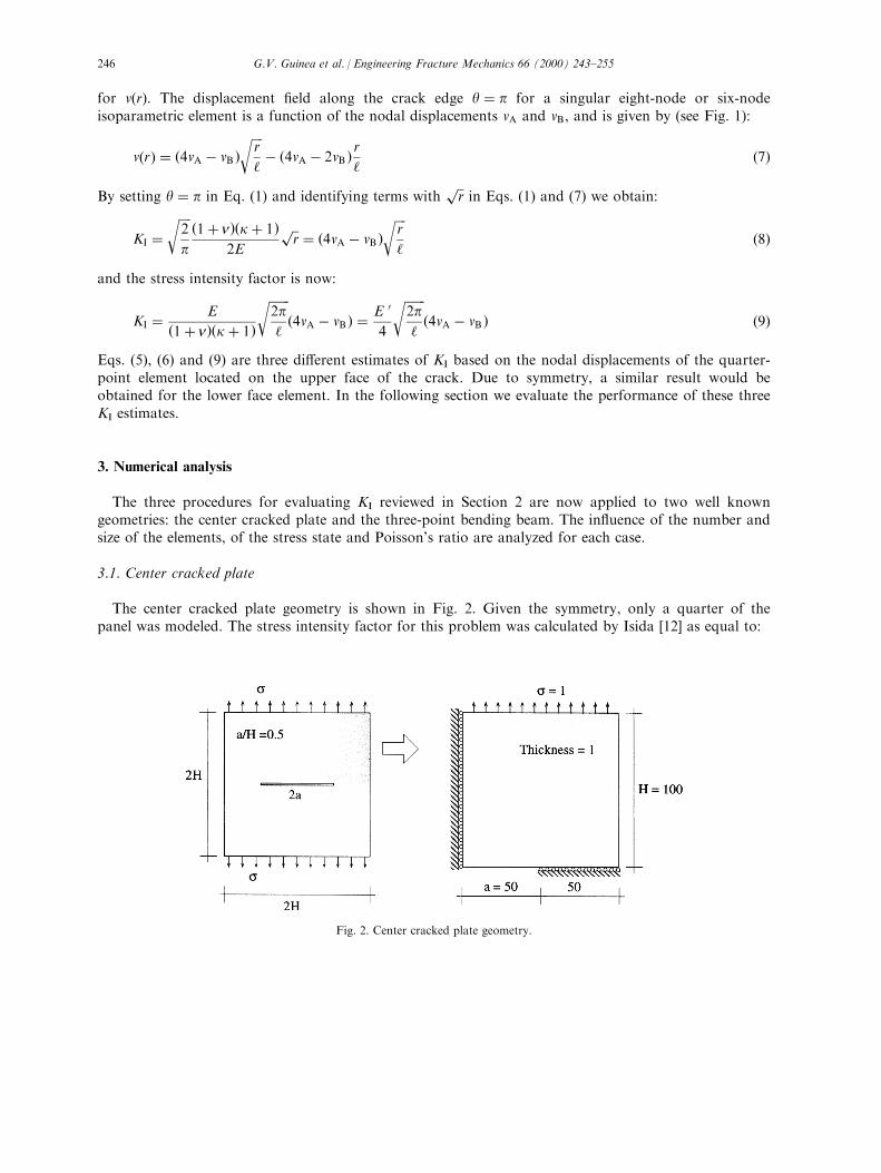
The center cracked plate geometry is shown in Fig. 2. Given the symmetry, only a quarter of thepanel was modeled. The stress intensity factor for this problem was calculated by Isida [12] as equal to:
Fig. 2. Center cracked plate geometry.
G.V. Guinea et al. / Engineering Fracture Mechanics 66 (2000) 243±255246
KI � 1:334s������pap �10�
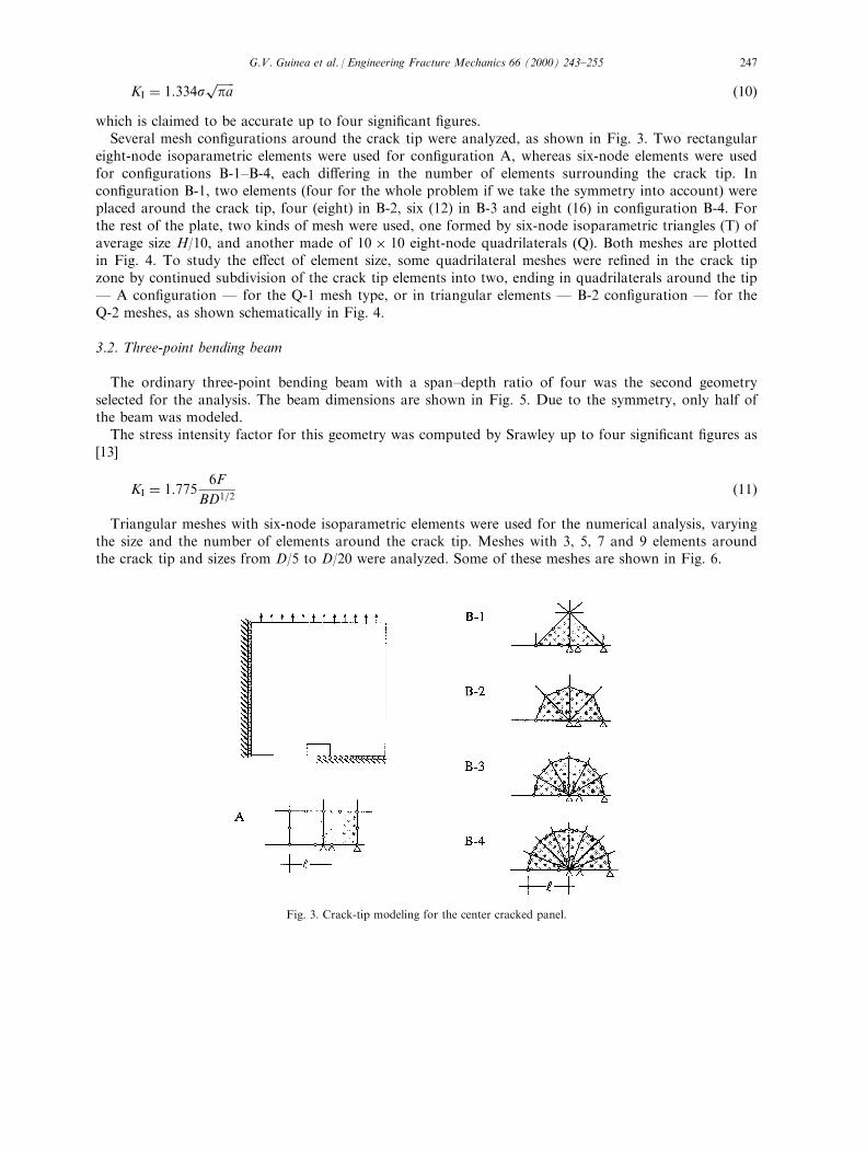
which is claimed to be accurate up to four signi®cant ®gures.Several mesh con®gurations around the crack tip were analyzed, as shown in Fig. 3. Two rectangular
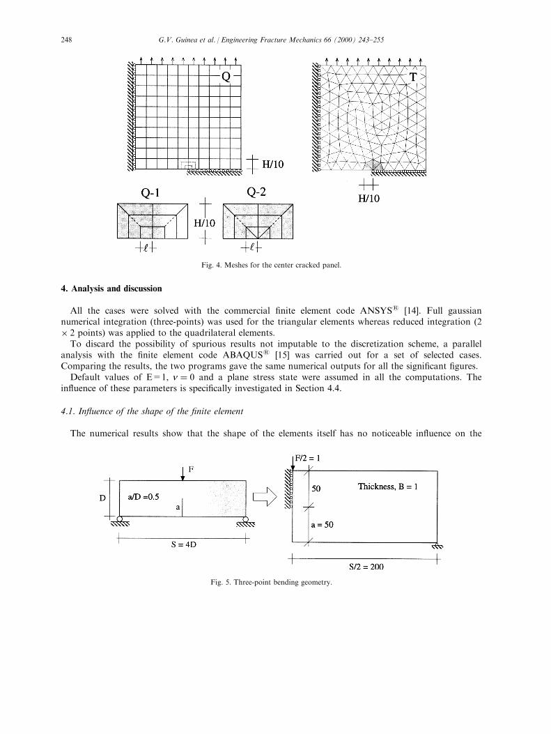
eight-node isoparametric elements were used for con®guration A, whereas six-node elements were usedfor con®gurations B-1±B-4, each di�ering in the number of elements surrounding the crack tip. Incon®guration B-1, two elements (four for the whole problem if we take the symmetry into account) wereplaced around the crack tip, four (eight) in B-2, six (12) in B-3 and eight (16) in con®guration B-4. Forthe rest of the plate, two kinds of mesh were used, one formed by six-node isoparametric triangles (T) ofaverage size H/10, and another made of 10 � 10 eight-node quadrilaterals (Q). Both meshes are plottedin Fig. 4. To study the e�ect of element size, some quadrilateral meshes were re®ned in the crack tipzone by continued subdivision of the crack tip elements into two, ending in quadrilaterals around the tipÐ A con®guration Ð for the Q-1 mesh type, or in triangular elements Ð B-2 con®guration Ð for theQ-2 meshes, as shown schematically in Fig. 4.
3.2. Three-point bending beam
The ordinary three-point bending beam with a span±depth ratio of four was the second geometryselected for the analysis. The beam dimensions are shown in Fig. 5. Due to the symmetry, only half ofthe beam was modeled.
The stress intensity factor for this geometry was computed by Srawley up to four signi®cant ®gures as[13]
KI � 1:7756F
BD1=2�11�
Triangular meshes with six-node isoparametric elements were used for the numerical analysis, varyingthe size and the number of elements around the crack tip. Meshes with 3, 5, 7 and 9 elements aroundthe crack tip and sizes from D/5 to D/20 were analyzed. Some of these meshes are shown in Fig. 6.
Fig. 3. Crack-tip modeling for the center cracked panel.
G.V. Guinea et al. / Engineering Fracture Mechanics 66 (2000) 243±255 247
4. Analysis and discussion
All the cases were solved with the commercial ®nite element code ANSYS1 [14]. Full gaussiannumerical integration (three-points) was used for the triangular elements whereas reduced integration (2� 2 points) was applied to the quadrilateral elements.
To discard the possibility of spurious results not imputable to the discretization scheme, a parallelanalysis with the ®nite element code ABAQUS1 [15] was carried out for a set of selected cases.Comparing the results, the two programs gave the same numerical outputs for all the signi®cant ®gures.
Default values of E=1, n � 0 and a plane stress state were assumed in all the computations. Thein¯uence of these parameters is speci®cally investigated in Section 4.4.
4.1. In¯uence of the shape of the ®nite element
The numerical results show that the shape of the elements itself has no noticeable in¯uence on the
Fig. 4. Meshes for the center cracked panel.
Fig. 5. Three-point bending geometry.
G.V. Guinea et al. / Engineering Fracture Mechanics 66 (2000) 243±255248
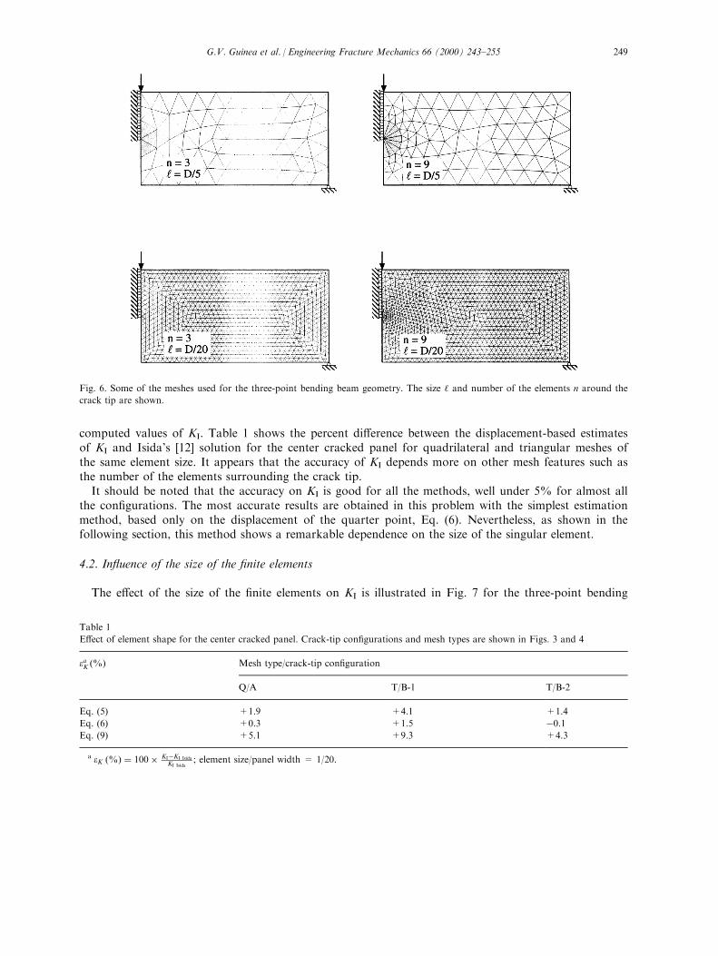
computed values of KI. Table 1 shows the percent di�erence between the displacement-based estimatesof KI and Isida's [12] solution for the center cracked panel for quadrilateral and triangular meshes ofthe same element size. It appears that the accuracy of KI depends more on other mesh features such asthe number of the elements surrounding the crack tip.
It should be noted that the accuracy on KI is good for all the methods, well under 5% for almost allthe con®gurations. The most accurate results are obtained in this problem with the simplest estimationmethod, based only on the displacement of the quarter point, Eq. (6). Nevertheless, as shown in thefollowing section, this method shows a remarkable dependence on the size of the singular element.
4.2. In¯uence of the size of the ®nite elements
The e�ect of the size of the ®nite elements on KI is illustrated in Fig. 7 for the three-point bending
Fig. 6. Some of the meshes used for the three-point bending beam geometry. The size ` and number of the elements n around the
crack tip are shown.
Table 1
E�ect of element shape for the center cracked panel. Crack-tip con®gurations and mesh types are shown in Figs. 3 and 4
eaK �%� Mesh type/crack-tip con®guration
Q/A T/B-1 T/B-2
Eq. (5) +1.9 +4.1 +1.4
Eq. (6) +0.3 +1.5 ÿ0.1Eq. (9) +5.1 +9.3 +4.3
a eK �%� � 100� KIÿKI Isida
KI Isida; element size/panel width = 1/20.
G.V. Guinea et al. / Engineering Fracture Mechanics 66 (2000) 243±255 249
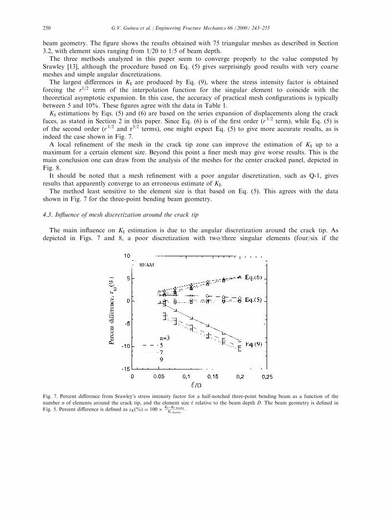
beam geometry. The ®gure shows the results obtained with 75 triangular meshes as described in Section3.2, with element sizes ranging from 1/20 to 1/5 of beam depth.
The three methods analyzed in this paper seem to converge properly to the value computed bySrawley [13], although the procedure based on Eq. (5) gives surprisingly good results with very coarsemeshes and simple angular discretizations.
The largest di�erences in KI are produced by Eq. (9), where the stress intensity factor is obtainedforcing the r1=2 term of the interpolation function for the singular element to coincide with thetheoretical asymptotic expansion. In this case, the accuracy of practical mesh con®gurations is typicallybetween 5 and 10%. These ®gures agree with the data in Table 1.
KI estimations by Eqs. (5) and (6) are based on the series expansion of displacements along the crackfaces, as stated in Section 2 in this paper. Since Eq. (6) is of the ®rst order (r 1/2 term), while Eq. (5) isof the second order (r 1/2 and r3/2 terms), one might expect Eq. (5) to give more accurate results, as isindeed the case shown in Fig. 7.
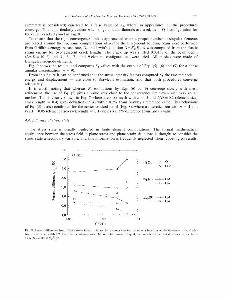
A local re®nement of the mesh in the crack tip zone can improve the estimation of KI up to amaximum for a certain element size. Beyond this point a ®ner mesh may give worse results. This is themain conclusion one can draw from the analysis of the meshes for the center cracked panel, depicted inFig. 8.
It should be noted that a mesh re®nement with a poor angular discretization, such as Q-1, givesresults that apparently converge to an erroneous estimate of KI.
The method least sensitive to the element size is that based on Eq. (5). This agrees with the datashown in Fig. 7 for the three-point bending beam geometry.
4.3. In¯uence of mesh discretization around the crack tip
The main in¯uence on KI estimation is due to the angular discretization around the crack tip. Asdepicted in Figs. 7 and 8, a poor discretization with two/three singular elements (four/six if the
Fig. 7. Percent di�erence from Srawley's stress intensity factor for a half-notched three-point bending beam as a function of the
number n of elements around the crack tip, and the element size ` relative to the beam depth D. The beam geometry is de®ned in
Fig. 5. Percent di�erence is de®ned as eK�%� � 100� KIÿKI Srawley
KI Srawley:
G.V. Guinea et al. / Engineering Fracture Mechanics 66 (2000) 243±255250
symmetry is considered) can lead to a false value of KI, where, in appearance, all the proceduresconverge. This is particularly evident when singular quadrilaterals are used, as in Q-1 con®guration forthe center cracked panel in Fig. 8.
To ensure that the right convergence limit is approached when a proper number of singular elementsare placed around the tip, some computations of KI for the three-point bending beam were performedfrom Gri�th's energy release rate, G, and Irwin's equation G=KI
2/E '. G was computed from the elasticstrain energy for two adjacent crack lengths. The crack tip was shifted 0.001% of the beam depth�Da=D � 10ÿ5� and 3-, 5-, 7-, and 9-element con®gurations were tried. All meshes were made oftriangular six-node elements.
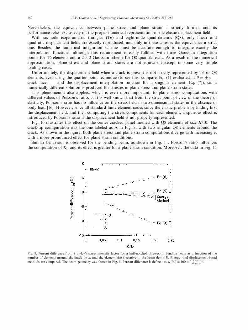
Fig. 9 shows the results, and compares KI values with the output of Eqs. (5), (6) and (9) for a denseangular discretization (n = 9).
From this ®gure it can be con®rmed that the stress intensity factors computed by the two methods Ðenergy and displacement Ð are close to Srawley's estimation, and that both procedures convergeadequately.
It is worth noting that whereas KI estimations by Eqs. (6) or (9) converge slowly with meshre®nement, the use of Eq. (5) gives a value very close to the convergence limit even with very roughmeshes. This is clearly shown in Fig. 7 where a coarse mesh with n = 5 and `=D � 0:2 (element size/crack length = 0.4) gives deviations in KI within 0.2% from Srawley's reference value. This behaviourof Eq. (5) is also con®rmed for the center cracked panel (Fig. 8), where a discretization with n = 4 and`=2H � 0:05 (element size/crack length = 0.1) yields a 0.3% di�erence from Isida's value.
4.4. In¯uence of stress state
The stress state is usually neglected in ®nite element computations. The formal mathematicalequivalence between the stress ®eld in plane stress and plane strain situations is thought to consider thestress state a secondary variable, and this information is frequently neglected when reporting KI results.
Fig. 8. Percent di�erence from Isida's stress intensity factor for a center cracked panel as a function of the tip-element size ` rela-
tive to the panel width 2H. Two mesh con®gurations, Q-1 and Q-2 shown in Fig. 4, are considered. Percent di�erence is calculated
as eK�%� � 100� KIÿKI Isida
KI Isida:
G.V. Guinea et al. / Engineering Fracture Mechanics 66 (2000) 243±255 251
Nevertheless, the equivalence between plane stress and plane strain is strictly formal, and itsperformance relies exclusively on the proper numerical representation of the elastic displacement ®eld.
With six-node isoparametric triangles (T6) and eight-node quadrilaterals (Q8), only linear andquadratic displacement ®elds are exactly reproduced, and only in these cases is the equivalence a strictone. Besides, the numerical integration scheme must be accurate enough to integrate exactly theinterpolation functions, although this requirement is easily ful®lled with three Gaussian integrationpoints for T6 elements and a 2 � 2 Gaussian scheme for Q8 quadrilaterals. As a result of the numericalapproximation, plane stress and plane strain states are not equivalent except in some very simpleloading cases.
Unfortunately, the displacement ®eld when a crack is present is not strictly represented by T6 or Q8elements, even using the quarter point technique (to see this, compare Eq. (1) evaluated at y �2p Ðcrack faces Ð and the displacement interpolation function for a singular element, Eq. (7)), so, anumerically di�erent solution is produced for stresses in plane stress and plane strain states.
This phenomenon also applies, which is even more important, to plane stress computations withdi�erent values of Poisson's ratio, n: It is well known that from the strict point of view of the theory ofelasticity, Poisson's ratio has no in¯uence on the stress ®eld in two-dimensional states in the absence ofbody load [16]. However, since all standard ®nite element codes solve the elastic problem by ®nding ®rstthe displacement ®eld, and then computing the stress components for each element, a spurious e�ect isintroduced by Poisson's ratio if the displacement ®eld is not properly represented.
Fig. 10 illustrates this e�ect on the center cracked panel meshed with Q8 elements of size H/10. Thecrack-tip con®guration was the one labeled as A in Fig. 3, with two singular Q8 elements around thecrack. As shown in the ®gure, both plane stress and plane strain computations diverge with increasing n,with a more pronounced e�ect for plane strain conditions.
Similar behaviour is observed for the bending beam, as shown in Fig. 11. Poisson's ratio in¯uencesthe computation of KI, and its e�ect is greater for a plane strain condition. Moreover, the data in Fig. 11
Fig. 9. Percent di�erence from Srawley's stress intensity factor for a half-notched three-point bending beam as a function of the
number of elements around the crack tip n, and the element size ` relative to the beam depth D. Energy- and displacement-based
methods are compared. The beam geometry was shown in Fig. 5. Percent di�erence is de®ned as eK�%� � 100� KIÿKI Srawley
KI Srawley:
G.V. Guinea et al. / Engineering Fracture Mechanics 66 (2000) 243±255252
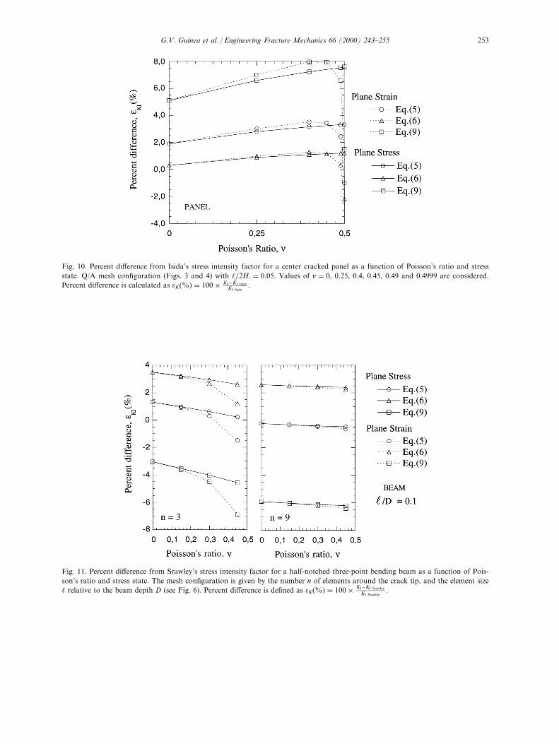
Fig. 10. Percent di�erence from Isida's stress intensity factor for a center cracked panel as a function of Poisson's ratio and stress
state. Q/A mesh con®guration (Figs. 3 and 4) with `=2H: � 0:05: Values of n � 0, 0.25, 0.4, 0.45, 0.49 and 0.4999 are considered.
Percent di�erence is calculated as eK�%� � 100� KIÿKI Isida
KI Isida:
Fig. 11. Percent di�erence from Srawley's stress intensity factor for a half-notched three-point bending beam as a function of Pois-
son's ratio and stress state. The mesh con®guration is given by the number n of elements around the crack tip, and the element size
` relative to the beam depth D (see Fig. 6). Percent di�erence is de®ned as eK�%� � 100� KIÿKI Srawley
KI Srawley:
G.V. Guinea et al. / Engineering Fracture Mechanics 66 (2000) 243±255 253
clearly show that the angular discretization plays a prominent role, and that a ®ner mesh around thecrack tip prevents undesired e�ects.
As regards the performance of Eqs. (5), (6) and (9) to estimate KI, all of them are in¯uenced to asimilar extent by n, and by the stress state situation. Then the only general recommendation which canbe given is to use a null Poisson's ratio �n � 0� for all the computations. With this null value, the stressstate has no in¯uence on the results.
5. Summary and conclusions
The numerical work shown in this paper can provide some guidelines to improve KI estimation inbidimensional problems.
Angular discretization around crack tip
First, it has been shown that the displacement extrapolation technique can give very accuratepredictions, even for coarse meshes, if a good angular discretization is made around the crack tip. Themethod based on a two-term extrapolation of the displacement ®eld, given by Eq. (5), brings the bestresults for large element sizes, with di�erences from the reference value of KI well under 1%.
Mesh re®nement
On the other hand, a mesh re®nement attending only to the element size, `, brings no bene®ts to theaccuracy of KI predictions. Even worse, if the angular discretization is too rough, e.g. 908 or 608elements, a wrong KI limit can be reached when ` tends to zero. A minimum angular discretization withsix elements around the tip, 308 each, is recommended.
Poisson's ratio
In the paper it is also shown that the stress state and Poisson's ratio n can negatively in¯uence theresults, particularly in any of these circumstances: plane strain, large value of n, and/or coarse angulardiscretization. To circumvent this e�ect, a null Poisson's coe�cient is recommended. Besides, a ®neangular discretization helps to minimize the error.
Acknowledgements
The authors gratefully acknowledge ®nancial support by the Spanish Comisio n Interministerial deCiencia y Tecnologi a (CICYT) under grants MAT97-1022 and MAT97-1007-C02-02.
References
1 Chan SK, Tuba IS, Wilson WK. On the ®nite element method in linear fracture mechanics. Engineering Fracture Mechanics
1970;2:1±17.
2 Shih CF, de Lorenzi HG, German MD. Crack extension modeling with singular quadratic isoparametric elements.
International Journal of Fracture 1976;12:647±51.
3 Parks DM. A sti�ness derivative ®nite element technique for determination of crack tip stress intensity factors. International
Journal of Fracture 1974;10:487±502.
G.V. Guinea et al. / Engineering Fracture Mechanics 66 (2000) 243±255254
4 de Lorenzi HG. Energy release rate calculations by the ®nite element method. Engineering Fracture Mechanics 1985;21:129±
43.
5 Moran B, Shih CF. A general treatment of crack tip contour integrals. International Journal of Fracture 1987;35:295±310.
6 Barsoum RS. Application of quadratic isoparametric ®nite elements in linear fracture mechanics. International Journal of
Fracture 1974;10:603±5.
7 Bank-Sills L, Sherman D. Comparison of methods for calculating stress intensity factors with quarter-point elements.
International Journal of Fracture 1986;32:127±40.
8 Liebowitz H, Sandhu JS, Lee JD, Menandro FCM. Computational fracture mechanics: research and application. Engineering
Fracture Mechanics 1995;50:653±70.
9 Kanninen MF, Popelar CH. Advanced fracture mechanics. New York: Oxford University Press, 1985.
10 Gallagher RH. A review of ®nite element techniques in fracture mechanics. In: Luxmore AR, Owen DRJ, editors. Numerical
methods in fracture mechanics. Swansea: Pineridge, 1978. p. 1±25.
11 Henshell RD, Shaw KG. Crack tip ®nite elements are unnecessary. International Journal for Numerical Methods in
Engineering 1975;9:495±507.
12 Isida M. E�ect of width and length on stress intensity factors of internally cracked plates under various boundary conditions.
International Journal of Fracture 1971;7:301±16.
13 Srawley JE. Wide range stress intensity factor expressions for ASTM E399 standard fracture toughness specimens.
International Journal of Fracture 1976;12:475±6.
14 ANSYS1, Release 5.5.1, Swanson Analysis Systems IP, Inc., Southpointe, PA, USA, 1998.
15 ABAQUS1, Release 5.7, Hibbit, Karlsson and Sorensen, Inc., Pawtucket, RI, USA, 1997.
16 Timoshenko SP, Goodier JN. Theory of elasticity. New York: McGraw-Hill, 1970.
G.V. Guinea et al. / Engineering Fracture Mechanics 66 (2000) 243±255 255