Embed Size (px)
Citation preview

KI-DISCUSTM MK 3 USER MANUAL REV1 January 2019


+44 (0)2392 695521 kidiscus.com [email protected]
KI-DISCUS
TM is a product designed and manufactured by CTS Europe Ltd.
14 Ordnance Court, Ackworth Road, Portsmouth, PO3 5RZ Registered office - CTS Europe Ltd. Station House, North Street, Havant, Hampshire, PO9 1QU.Registered in England & Wales – Registration N° 07306969

Contents
Introduction _____________________________________________________________________________ 3
Functional Description ____________________________________________________ 3
Safety ___________________________________________________________________________________ 4
Warnings with This Guide__________________________________________________ 4
General Safety Instructions ________________________________________________ 5
Safety Instructions for Operating and Servicing ______________________________ 6
Principle of Operation ____________________________________________________________________ 7
Equipment Overview______________________________________________________________________ 8
Cabinet__________________________________________________________________ 9
Cabinet Control Panel ____________________________________________________ 10
Tool Box ________________________________________________________________ 11
Consumables __________________________________ 11
Spray Generator Assembly ______________________ 15
KI-DISCUSTM
Tests _______________________________________________________________________ 16
Context ________________________________________________________________ 16
Test Requirements _____________________________ 16
Regular Testing of Cabinets _____________________ 16
Preparations for Test ____________________________________________________________________ 17
Positioning the KI-DISCUSTM
Cabinet _______________________________________ 17
‘Y’ piece, ‘T’ piece & Artificial Arm Assembly ________________________________ 17
Spray Generator Installation ______________________________________________ 19
Spray Generator Connection _____________________ 20
Pre-Test Checks _________________________________________________________________________ 20
Fluid Delivery Pre-test Check. Tubing Installation. ___________________________ 21
priming the fluid delivery system __________________________________________ 23
Priming _______________________________________ 23
Quantity Test __________________________________ 24
Set Up_________________________________________ 24
Setting Time & Date _____________________________________________________ 28
Other Manual Control Functions __________________________________________ 29
Vacuum Pump _________________________________ 29
Spray Generator ________________________________ 29
Spray Generator Pre-test Check ___________________________________________ 30
Preparation for Tests ____________________________________________________________________ 30

Loading Sensor Heads ____________________________________________________________________ 30
Background Test ________________________________________________________________________ 31
Operation ______________________________________________________________ 31
Running a Full Automatic Test ____________________________________________________________ 34
Automatic Test Start _____________________________________________________ 34
Report Printing _________________________________________________________ 35
Results Analysis _________________________________________________________ 36
Examination of the Filter Membranes _____________ 36
Interpreting Results _____________________________________________________ 37
Alarms _________________________________________________________________________________ 38
Level One - Low Level Error ______________________ 38
Level Two - High level error ______________________ 38
Trouble Shooting and Alarm Functions _____________________________________ 39
Alarm Reset ____________________________________________________________ 39
Troubleshooting ________________________________________________________ 40
Maintenance of KI-DISCUS TM
System _______________________________________________________ 41
Calibration ______________________________________________________________________________ 41
Technical Specification ___________________________________________________________________ 42
Spares List ______________________________________________________________________________ 43
Product Decommissioning and Disposal ____________________________________________________ 44
Product Warranty Statement _____________________________________________________________ 44
Declaration of Conformity ________________________________________________________________ 45

Rev1 January 2019 - kidiscus.com 3
Keep this instruction manual with the machine. If this documentation is lost or damaged, obtain a
replacement from the manufacturer.
Introduction
Thank you for purchasing a KI-DISCUSTM
product.
FUNCTIONAL DESCRIPTION
The KI-DISCUSTM
system has been designed to enable aperture/operator protection factors (and
where appropriate, product protection and cross contamination factors) to be measured for Class I
and Class II open-fronted microbiological safety cabinets in accordance with EN12469:2000. (It can
also be used for special hybrid facilities such as carcinogen and radio-pharmaceutical cabinets and for
general purpose laboratory fume cupboards).
Unlike test methods employing a micro-biological aerosol challenge this technique enables cabinets
to be evaluated without risk of microbial contamination, of either the containment facility or the
laboratory. Another advantage is that the results of the tests are available within a few minutes and
can be permanently retained.
KI-DISCUSTM
MK 3 is a safety measuring device which must be used in accordance with the
instructions in order to provide the indicated level of protection.
KI-DISCUSTM
MK 3 is manufactured by CTS Europe Ltd. CTS Europe Ltd accept no liability for any injury
or damage caused by improper use.

Rev1 January 2019 - kidiscus.com 4
Safety
WARNINGS WITH THIS GUIDE
You will find in this manual various warning and safety instructions. The type of hazard is identified
by a symbol and a title. This safety information must be observed.
Warning
This symbol indicates a hazardous situation in which there is an immediate danger of death, serious
injury or damage to health if instructions are not followed.
Attention
This symbol indicates a hazardous situation in which there may be a risk of minor injury or damage
to health if instructions are not followed.
Information
This symbol indicates important details on the proper use of the system.
Useful Information
This symbol indicates useful information.
Chemical Warnings
H225 Highly flammable liquid and vapour
H302 Harmful if swallowed

Rev1 January 2019 - kidiscus.com 5
GENERAL SAFETY INSTRUCTIONS
Please note the following general safety precautions
Information
For your own safety please note the following:
Working safely always takes priority at all times.
Staff must be trained before working with active, hazardous / or toxic substances.
Please read these instructions carefully before use.
Keep the manual close by the equipment so that it is easy to refer to.
The information in this guide will help you to work safely and without exposure to
contaminants.
For all questions concerning the application or correct use of this system please contact
This document assumes that the user is familiar with all relevant guidelines and safety
protocols for working in a laboratory environment and is competent in the use of the
device.
Warning – Spray Generator LED lamp
The spray generator LED lamp is of a high brightness type & is used to illuminate the aerosol
produced by the generator. This assists the user is confirming aerosol generation. The user is
protected from viewing the LED lamp directly by the spray generator arm assembly. Never use
optical instruments to view the lamp directly. If the arm should become damaged and the LED lamp
becomes directly visible as a result, the equipment must not be used.

Rev1 January 2019 - kidiscus.com 6
SAFETY INSTRUCTIONS FOR OPERATING AND SERVICING
Information – Operating Conditions
Avoid failure due to condensation or heat.
Operate the system at a room temperature of 15°-25°C and 5-80% RH to avoid damage caused by
condensation or by overheating.
This equipment is intended for indoor use only.
Use only on a stable, level surface. Do not tilt.
Warning – Electrical Safety
Follow the power supply requirements listed below, failure to do so may result in fire, electric
shock or incorrect operation.
The system must only be operated on the voltage and frequency shown below.
POWER SUPPLY VOLTAGE POWER CONSUMPTION FREQUENCY
100V-120VAC and 220V-240VAC 220w typ. 50-60Hz
The power supply should be stable and the current capacity sufficient to operate the
machine. If the power supply fluctuates, the system could operate incorrectly.
A modified or damaged mains cable may result in fire, electrical shock or malfunction. Do not
modify. If the cable becomes damaged, contact the manufacturer for a replacement.
Keep the mains cable away from hot items.
Do not place heavy objects on the mains cable.
Do not place the mains cable where it may present a trip hazard or cause an obstruction.
Do not excessively bend or pull on the mains cable.
Warning – Maintenance
Unplug the machine before inspection, maintenance or part replacement.
Repairs requiring removal of the internal cover or top panel should be performed by an
engineer appointed by the manufacturer. Never remove any covers or panels. There are
no user serviceable parts inside.
Attention – Maintenance
Improper maintenance, repair or upgrade work can cause considerable damage.
Cleaning, maintenance and repairs should be performed only by persons who are trained for the
activities and understand the possible dangers. For safety reasons, unauthorised alterations or
changes to the device are not permitted. Genuine parts and accessories are designed specifically
for this equipment. No liability is accepted for damage that is caused by use of non-original parts or
accessories.

Rev1 January 2019 - kidiscus.com 7
Attention – Operation
Keep equipment dry. Spillages should be cleaned up immediately.
Useful Information
In an emergency situation, press the “O” Side of the green power switch on the top panel to turn
off the machine.
Principle of Operation
A fine aerosol of potassium iodide droplets, produced by a spray generator, is used as a challenge
aerosol to measure the containment of a cabinet (or fume cupboard). Four Centripetal sensor heads
sample the air outside (or inside the cabinet- depending on the nature of the test) and deposit any
potassium iodide particles that are entrained in the sampled air on to filter membranes. At the end
of the sampling period the filter membranes are placed in a solution of palladium chloride
whereupon the potassium iodide “develops” to form clearly visible and easily identified brown dots
of Palladium Iodide.
Knowledge of a number of the droplets in the challenge produced by the spray generator and of
the number collected in the sensor heads enables the protection factor for the cabinet to be
evaluated. A satisfactory protection factor is the criterion by which open-fronted micro-biological
safety cabinets are assessed and this test method is described in EN12469:2000.
When this performance is confirmed at commissioning or during routine maintenance there should
be no more than 62 brown dots on any of the KI-DISCUSTM
filter membranes after development in
palladium chloride. The figure of 62 results from evaluating the equation in the above section for
an operator protection requirement of 105.

Rev1 January 2019 - kidiscus.com 8
Equipment Overview
KI-DISCUSTM
is designed for one person operation and comprises of two parts, cabinet and tool box,
which can be separated for ease of transportation.
The cabinet and tool box house all the apparatus and equipment required for the test.
Useful Information
Note that the cabinet and tool box are separate items. The lids of both cabinet and tool box
may be lifted off.

Rev1 January 2019 - kidiscus.com 9
CABINET
User Manual Instruction user guide.
Artificial Arm Used to simulate disturbances to the air flow, caused by an
operator’s arm in the aperture of an open-fronted cabinet.
Y and T Pieces Sensor head mounting assembly.
Mains Cable Used to connect mains power to the AC inlet at the rear of
the machine.
Pump Tubing Used to supply Potassium Iodide solution from the reservoir
bottle to the spray generator, via the Peristaltic Pump
Manual
Artificial Arm B
Pump Tubing
Mains Cable
Y and T pieces
Artificial Arm A

Rev1 January 2019 - kidiscus.com 10
CABINET CONTROL PANEL
Mains Power Switch Used to turn the machine on and off. Illuminated when switched
on.
Alarm Indicator Illuminates and sounds if a test error occurs or performance falls
outside specifications during cycle.
Vacuum Tube and
Locking Screw
Y piece insert connection point.
Damper Fluid flow regulator.
Peristaltic Pump
Used to deliver Potassium iodide solution to the spinning disc. The
pump speed is factory set.
Printer Connector
HMI – Control Screen
Mains Power Switch
Alarm indicator
Vacuum Tube Damper
Pump
Spray Generator Socket

Rev1 January 2019 - kidiscus.com 11
TOOL BOX
The tool box holds the equipment,
consumables and tools to set up
KI-DISCUSTM
and carry out tests.
Consumables
Potassium Iodide
Used to produce the challenge aerosol.
Potassium Iodide solution is pumped to the
nebuliser, where it is dispensed onto the Spray
Generator spinning disc. The disc rotates at high
speed, creating an aerosol.
Current MSDS are available on request.
Warning – Caution
The Potassium Iodide solution used for the test is flammable and corrosive to un-treated steel.
Potassium Iodide oxidises rapidly in the atmosphere and leaves a yellow stain.
It is recommended to place a protective sheet or paper on the floor in front of the
cabinet being tested.
Wipe clean the cabinet thoroughly after testing.
Use a cloth dampened in water for cleaning, or contact the cabinet manufacturer for
suitable cleaning advice.
Wipe up any spillages immediately using water with a small concentration of detergent.

Rev1 January 2019 - kidiscus.com 12
Information
When the KI-DISCUSTM
system is used to measure the operator protection factor in facilities used
for microelectronics research or production it is generally not possible to use potassium iodide
as the challenge aerosol, as this would provide a containment which is incompatible with the
work.
In such containment circumstances it may be possible to substitute a solution of ammonium
iodide in the aerosol generator and carry out tests in the same way as described earlier for Class
I and Class II cabinets. The ammonium iodide solution should again be 1.31% dissolved in alcohol
or industrial methylated spirits. The filters are developed as usual in the palladium chloride
solution. Seek advice from the manufacturer and the laboratory equipment owner in case of any
doubt.
Palladium Chloride
At the end of the test the filter membranes are
placed in a palladium chloride solution. This
‘develops’ the filter membrane so that any escaping
particles become visible as brown dots.
Current MSDS are available on request.
De-ionised Water
De-ionised (or distilled) water is used to rinse the
filter membrane. This concludes the development
process.
Sensor head filters
3μm pore size, white, 25mm diameter, hydrophilic,
mixed cellulose esters (MCE) discs.
Recommended Merck/Millipore filters, reference
SSWP02500, are available from CTS.
Current MSDS are available on request.
The individual filters are separated
by blue sleeves. Make sure these
are discarded before placing the
filter into the sensor head.

Rev1 January 2019 - kidiscus.com 13
Tools
Measuring Cylinder
Used to confirm quantity of potassium iodide
solution delivered to Spray Generator.
20ml to be delivered in 9 minutes ± 30 seconds.
Petri Dish x 2
1. Dish 1 - One half filled with Palladium Chloride
solution - used when floating sampled filters.
2. Dish 2 - One half filled with de-ionised water for
filter rinsing.
Vacuum gauge
Used to confirm* individual sensor head vacuum
reading of 8 inches wg / -20mbar.
*Vacuum is set and monitored automatically by the
machine.
Useful Information
NB. Some fluctuation in vacuum
generation may be observed. This is
normal but should not exceed +/- 1.5mbar.
Tweezers x 3
A. Millipore tweezers – used when loading fresh
filters to sensor heads.
B. Fine point tweezers – used when removing
sampled air filter from sensor heads and
‘floating’ filter on palladium chloride filled petri
dish.
C. Spade end tweezers – used when removing
filter from palladium chloride solution, then
used for rinsing in de-ionised water and placing.
A C
A
B
A

Rev1 January 2019 - kidiscus.com 14
Reservoir Bottle & Clip
Filled with potassium iodide solution – silicone
tubing connects the reservoir bottle to the spray
generator via the peristaltic pump and damper.
Magnifier & Graticule
Used to view and determine the number of brown
dots found on the filters.
Distance Piece Gauge
Used when measuring set distances –divided into
50mm x 4
Tools & Spares
A. Feeler gauge - used to determine and set
distance of 0.1mm between the spinning disc
and the nebuliser nozzle.
B. Allen key - used to release/tighten the nebuliser
nozzle securing screw, if adjustments need to
be made to achieve a 0.1mm gap between end
of nebuliser nozzle & top surface of spinning
disc.
C. Tommy bar - used in replacing the spinning disc
and hub assembly.
D. Spare “O” rings for sensor heads.
Large size - used in sensor heads (Sensor cap
seal).
Medium size - used in rising arm.
Small size - used in sensor heads (Sensor
connector seal).
Printer & Cable
Connected to the KI-DISCUSTM
control panel,
enabling the user to obtain a paper report of the KI-
DISCUSTM
test performance.
AB
D B C

Rev1 January 2019 - kidiscus.com 15
Spray Generator Assembly
The spray generator incorporates a spinning disc rotating at 28,000 rpm ±500 rpm.
Potassium iodide solution, contained in the reservoir bottle, is delivered to the spinning disc
through silicone tubing, via a peristaltic pump & damper mounted on the control panel. The
solution is dispensed on the centre of the spinning disc via the nebuliser. The gap between the end
of the nebuliser nozzle and the spinning disc is set to 0.1mm by means of the feeler gauge
provided, to ensure an even aerosol. The spray generator assembly also comprises a laboratory
stand which is used to hold the spray generator at different heights when required.
Sensor Heads x 4
Air enters the sensor head through the orifice in the
cap and is directed to the filter. Potassium iodide
particles escaping from the Microbiological Safety
Cabinet (MSC) cabinet are deposited on the filter.
Air flow through the sensor heads is controlled
automatically. Suction is provided by a centrifugal fan
housed within the cabinet.
Laboratory Stand Nebuliser
Allen Key
Feeler Gauge
Grub Screw
Spinning Discs

Rev1 January 2019 - kidiscus.com 16
KI-DISCUSTM Tests
CONTEXT
Test Requirements
EN12469:2000 Specifies replicate testing in annex C.1.2 that a type test for aperture/operator
protection should be made on production example of a safety cabinet, and that five replicated tests
should produce operator protection factors of 105 or above. When this performance is confirmed at
commissioning or during routine maintenance there should be no more than 62 brown dots on any
of the KI-DISCUSTM
filter membranes after development in palladium chloride. The figure of 62
results from evaluating the equation in the above section for an operator protection requirement
of 105.
If the operator protection factor is to be consistent with the values specified in EN12469:2000 at
least 5 consecutive tests at specified distances should be performed, each of which results in a
protection factor of not less than 105 evaluated for each sensor head.
Practical experience has shown that well set-up cabinets in good environmental conditions will
have approx. 5-30 dots per filter.
Regular Testing of Cabinets
It is recommended that maintenance and testing of all classes of micro-biological safety cabinets be
carried out as a regular routine. The Control of Substances Hazardous to Health Regulations
(COSHH) requires that any control measure such as safety cabinets are maintained in an efficient
state. Safety cabinets should be thoroughly examined and tested at least once every 14 months
(more frequently in special circumstances, e.g. at least every 6 months for work at containment
levels 3 and 4) and records of the examination and tests, and of any repairs carried out should be
kept for at least 5 years.

Rev1 January 2019 - kidiscus.com 17
Preparations for Test
POSITIONING THE KI-DISCUSTM CABINET
Useful Information
Potassium Iodide oxidises rapidly in the atmosphere and can leave a yellow stain. It is
recommended to place a protective sheet or paper on the floor in front of the cabinet being tested.
1. The KI-DISCUSTM
cabinet is placed upright at the front centre of the safety cabinet aperture with
the control panel facing the user.
2. Connect one end of the mains cable to a suitable electrical supply and the other to the rear inlet
socket on the KI-DISCUSTM
cabinet. Ensure the cable is placed so that it does not present a hazard.
3. Do not switch on KI-DISCUSTM
at this stage. If KI-DISCUSTM
powers up, switch off using the green
power switch on the cabinet control panel.
‘Y’ PIECE, ‘T’ PIECE & ARTIFICIAL ARM ASSEMBLY
1. Remove the ‘Y’ piece and ‘T’ piece from the KI-DISCUSTM
cabinet. Loosen the lock screw on the ‘Y’
piece and gently insert the ‘T’ piece. Do not tighten the lock screw at this stage.
2. Loosen the lock screw on the vacuum tube. Take the ‘Y’ piece (now connected to the ‘T’ piece) and
insert the lower tube of the ‘Y’ piece gently into the vacuum tube. If there is much resistance when
attempting to insert tubes, a little silicone grease may be placed on the ‘O’ ring seals located towards
the top of the tubes.
‘T’ piece
‘Y’ piece
Lock screw
Lock screw

Rev1 January 2019 - kidiscus.com 18
3. Remove artificial arm sections ’A’ and ‘B’ from the KI-DISCUSTM
cabinet. Place arm section ‘B’ in the
cabinet under test, so that the ‘foot’ plate is facing the wall of the cabinet under test. The ‘key’
hole at the opposite end of arm section ‘B’ must be hooked onto the locating lug at the top of the
‘Y’ piece.
4. Install arm section ‘A’ onto the end of arm section ’B’. The complete arm section, comprising section
‘A’ and section ‘B’, should now rest on the ‘Y’ piece. The artificial arm should protrude a minimum of
250 mm into the laboratory from the plane of the aperture.
5. Adjust the height of the ‘Y’ piece, so that the complete arm section is horizontal. Use the spirit level
in arm section ‘A’ for this purpose. Tighten the lock screw on the vacuum tube.
6. Ensuring the ‘T’ piece is located securely in the ‘Y’ piece, install sensor heads onto the ‘X1’ and ‘Y1’
sections of the ‘T’ piece. The sensor heads air inlet hole must face the cabinet aperture. Adjust the
height of the ‘T’ piece, so that the centre of the sensor heads’ air inlet holes are level with the top
of the aperture of the cabinet under test. Tighten the lock screw on the ‘Y’ piece. It will be
necessary to temporarily remove section ‘A’ of the artificial arm when making this adjustment.
7. Install sensor heads onto the ‘X’ and ‘Y’ sections of the ‘Y’ piece.
8. Carefully manoeuvre the KI-DISCUSTM
cabinet, so that the air inlet holes of all sensor heads are
150mm – 160mm from the cabinet aperture plane.
Locating Lug Arm Section B Arm Section A Arm Section B

Rev1 January 2019 - kidiscus.com 19
SPRAY GENERATOR INSTALLATION
The spray generator positioning changes according to the microbiological cabinet type, the
following information describes the positioning for Class I and Class II Safety Cabinets.
For Class I Safety Cabinets
Place the aerosol generator centrally in the cabinet below the artificial arm and use the measuring
gauge provided so that the leading edge of the spinning disc is 100 mm behind the plane of the
aperture (Figure 3)
Fig. 3
For Class II Safety Cabinets
Place the aerosol generator on the laboratory stand centrally in the cabinet so that the centre of
the spinning disc is directly above the centre of the artificial arm and the leading edge of the disc is
100 mm behind the plane of the aperture. Adjust the height of the spray generator so that the
spinning disc is level with the upper edge of the aperture (Figure 4).
Fig. 4

Rev1 January 2019 - kidiscus.com 20
Spray Generator Connection
Connect the spray generator cable plug to the spray generator connector socket on the cabinet
control panel, paying attention to the orientation of the plug. A locking ring on the plug is rotated
clockwise to secure the plug to the socket and rotated anti-clockwise to release. Never pull the
cable at the plug or spray generator end. Never connect or disconnect the spray generator while
running an automatic test. Doing so may cause erratic operation or possible damage to the spray
generator motor drive system.
Pre-Test Checks
These pre-test checks verify fluid delivery, fluid quantity & nebuliser to spinning disc distance.
Information – Testing
Ensure these pre-test checks are carried out before performing tests. Failure to do so may cause
the system to operate incorrectly.
Information – User commands
User commands, except emergency stop, are input through the touch-sensitive screen and
the membrane panel.
Press ‘O’ on the ‘POWER’ rocker switch for an Emergency Stop.
Finger pressure when using the screen & panel should be light to moderate. Use of other
implements may damage the screen.

Rev1 January 2019 - kidiscus.com 21
FLUID DELIVERY PRE-TEST CHECK. TUBING INSTALLATION.
Information – Test Accuracy
Perform the fluid delivery pre-test check at the start of every day the system is in use and when
tubing is replaced. Failure to perform this check may affect the accuracy of test results.
Information – Tubing
NB! KI-DISCUSTM
is calibrated to use the following silicone tubing only (1.25 mm wall - 2.00mm
bore). Use of other tubing types may result in unreliable potassium iodide solution delivery.
Do not use old, worn or damaged tubing.
Tubing may be obtained from CTS under part number: 3/440008
1. Carefully fill the reservoir bottle with potassium iodide solution and place the filled bottle on a
nearby stable surface. The nearby surface should ideally be at the same height or slightly higher
than the peristaltic pump. If no nearby surface is available, securely clip the bottle to the side of KI-
DISCUSTM
using the supplied reservoir bottle clip.
2. Using the supplied allen key, loosen the nebuliser securing screw located towards the end of the
arm on the spray generator. Remove the nebuliser from the spray generator arm.
3. Connect a 1.2 metre length of tubing from the spray generator nebuliser to the damper on the
cabinet control panel. Use of lengths less than 1.2 metres are not recommended and may adversely
affect pump dosing accuracy. Ensure there are no sharp bends in the tubing.
4. Place the nebuliser in the supplied measuring cylinder. The nebuliser should be above the 20ml
graduation. It may be necessary to place the measuring cylinder in a stand to prevent it from
tipping.
5. Open the peristaltic pump lid. Connect a 80 – 100 cm length of tubing to the opposite damper
connector. Use of lengths less than 80 cm or greater than 100 cm are not recommended and may
affect pump dosing accuracy. Place the tubing in between the pump rollers and inside wall. The
tubing must not be twisted or stretched. Close the lid.
a.
b.
c.
d.

Rev1 January 2019 - kidiscus.com 22
6. Connect the other end of the tubing to the reservoir bottle nozzle.
7. Press the ‘POWER’ rocker switch. The ‘POWER’ switch will illuminate.
8. When prompted by the following screen, touch “Enter System”.
9. The Main Menu will appear.
10. Proceed with the priming of the fluid delivery system.

Rev1 January 2019 - kidiscus.com 23
PRIMING THE FLUID DELIVERY SYSTEM
Information – Priming the fluid delivery system
When performing a fluid delivery pre-test check, ensure the nebuliser is placed in the measuring
cylinder, above the 20ml graduation mark.
Information – Tests
Priming the fluid delivery system is necessary before:
Performing a fluid quantity test.
Performing the first full automatic test.
Priming
1. Touch “Prime Dose Pump”. The Dose Pump Priming screen appears.
Three pump functions are available and each toggles between two modes. The functions are
selected by touching the related grey ‘button’.
FUNCTION Direction Speed Start/Stop
MODES Forward/ Reverse Slow / Fast Start / Stop
2. Ensure reservoir bottle is filled with potassium iodide solution.
3. Set Direction to ‘Forward’.
4. Set Speed to ‘Slow’.
5. Set Start/Stop to ‘Start’.
6. Pay attention to the fluid travelling along the tubing.
The fluid will now be drawn from the reservoir bottle, through the pump and damper, up to the
nebuliser. The leading edge of the fluid can be seen through the translucent tubing. Once the fluid
enters the nebuliser, it will exit the nozzle into the measuring cylinder.
Rev1 January 2019 - kidiscus.com 24
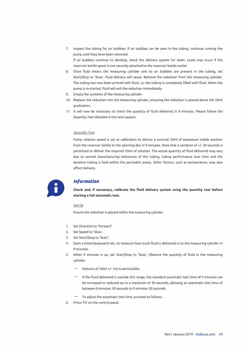
7. Inspect the tubing for air bubbles. If air bubbles can be seen in the tubing, continue running the
pump until they have been removed.
If air bubbles continue to develop, check the delivery system for leaks. Leaks may occur if the
reservoir bottle spout is not securely attached to the reservoir bottle outlet.
8. Once fluid enters the measuring cylinder and no air bubbles are present in the tubing, set
Start/Stop to ‘Stop’. Fluid delivery will cease. Remove the nebuliser from the measuring cylinder.
The tubing has now been primed with fluid, i.e. the tubing is completely filled with fluid. When the
pump is re-started, fluid will exit the nebuliser immediately.
9. Empty the contents of the measuring cylinder.
10. Replace the nebuliser into the measuring cylinder, ensuring the nebuliser is placed above the 20ml
graduation.
11. It will now be necessary to check the quantity of fluid delivered in 9 minutes. Please follow the
Quantity Test detailed in the next session.
Quantity Test
Pump rotation speed is set at calibration to deliver a nominal 20ml of potassium iodide solution
from the reservoir bottle to the spinning disc in 9 minutes. Note that a variation of +/- 30 seconds is
permitted to deliver the required 20ml of solution. The actual quantity of fluid delivered may vary
due to normal manufacturing tolerances of the tubing, tubing performance over time and the
duration tubing is held within the peristaltic pump. Other factors, such as temperature, may also
affect delivery.
Information
Check and, if necessary, calibrate the fluid delivery system using the quantity test before
starting a full automatic test.
Set Up
Ensure the nebuliser is placed within the measuring cylinder.
1. Set Direction to ‘Forward’.
2. Set Speed to ‘Slow’.
3. Set Start/Stop to ‘Start’.
4. Start a timer/stopwatch etc. to measure how much fluid is delivered in to the measuring cylinder in
9 minutes.
5. When 9 minutes is up, set Start/Stop to ‘Stop’. Observe the quantity of fluid in the measuring
cylinder.
Delivery of 20ml +/- 1ml is permissible.
If the fluid delivered is outside this range, the standard automatic test time of 9 minutes can
be increased or reduced up to a maximum of 30 seconds, allowing an automatic test time of
between 8 minutes 30 seconds to 9 minutes 30 seconds.
To adjust the automatic test time, proceed as follows.
6. Press ‘F4’ on the control panel.

Rev1 January 2019 - kidiscus.com 25
Useful Information
‘F4’ returns the user to the previous operation screen. It always performs the same function.
7. Touch ‘Manual Functions’.
8. Touch the ‘Auto’ button. The indicator will now show ‘Manual’. KI-DISCUSTM
is now in manual mode.
No automatic test is possible in manual mode.

Rev1 January 2019 - kidiscus.com 26
9. Touch the adjustment button in the Dose Pump section.
The following screen will appear.
10. Touch the ‘Modifier’ box. A keyboard will appear. It will now be possible to enter a numerical figure
to vary the time of the automatic test e.g. ‘+15’ will extend the test time by 15 seconds, ‘-15’ will
reduce the test time by 15 seconds. Increasing the time will allow a greater quantity of fluid to be
delivered. Reducing the time will allow less fluid to be delivered. Adjust the time accordingly. It
may be necessary to run a few delivery tests at different time settings to obtain satisfactory fluid
delivery. Once set, the modifier retains the value set until KI-DISCUS TM
is turned off or power is
removed. The Delivery Period is pre-set and not user adjustable. NB! Do not release/re-clamp the
tubing in the pump whilst performing a Quantity Test or after completion of the Quantity Test. Doing
so will void the Quantity Test calibration.

Rev1 January 2019 - kidiscus.com 27
11. Press ‘F4’ to return to the previous screen. Touch the ‘Manual’ button, so that ‘Auto’ is shown.
KI-DISCUSTM
is now in ‘Auto’ mode. Remember to return the machine to ‘Auto’ mode. No automatic
tests are possible in ‘Manual’ mode.
Remove the nebuliser from the measuring cylinder & install it into the spray generator arm. Ensure
a gap of 0.1mm exists between the end of the nebuliser nozzle and the surface of the spinning disc.
(Use the feeler gauge for this purpose). Tighten the securing screw using the supplied allen key to
lock the nebuliser in place. Position the spray generator back in the correct position within the
cabinet under test.
12. Press ‘F4’ to return to the Main Menu.
Useful Information
The adjustment button is only available in ‘Manual Control’ mode.
Its function is limited to Dose (Peristaltic) Pump operation only.
It performs an engineering/service function in other modes – these modes are not available to user.
Attempting to use this function in any other mode than Dose Pump operation will prompt the user
for a password.
Press ‘Cancel’ to return to the previous screen.

Rev1 January 2019 - kidiscus.com 28
SETTING TIME & DATE
The ‘Set Date’ button is used to set the internal clock time and date. This information is primarily used
for report data. KI Discus will still perform tests if the correct time and date have not been set.
Press the ‘Manual Functions’ button in the Main Menu.
The ‘Manual Control’ screen will appear.
The time & date are shown in the top right hand corner of the screen.
Press the ‘Set Date’ button.
Follow the on screen instructions for entering time and date.
Use the on screen keyboard to enter data.
The setting format is shown in orange to the right of the ‘Set Time’ and ‘Set Date’ buttons.
Make sure the correct setting format is used. Failure to do so may result in the wrong time and/or
date being displayed, or failure to accept time or date information.
Press ‘F4’ to return to the previous screen.

Rev1 January 2019 - kidiscus.com 29
OTHER MANUAL CONTROL FUNCTIONS
The Vacuum Pump motor & Spray Generator may be turned on and off independently in the Manual
Control mode.
This facility is intended for basic system checks and not for cabinet testing.
Information
‘Manual’ mode must be selected when using this facility. Ensure ‘Manual’ is displayed in the bottom left
corner of the Manual Control screen. Touch the ‘Auto/Manual’ button so that ‘Manual’ is displayed.
This facility is not available in ‘Auto’ mode.
Vacuum Pump
The Vacuum Pump motor may be started or stopped by pressing the grey button. The button text
will indicate motor status (‘running’ or ‘stopped’).
NB.: The vacuum motor will run at a pre-set speed when operated manually. Vacuum motor power is
displayed arbitrarily as a % figure. Vacuum generated is displayed in mBar below vacuum motor power.
Although vacuum level is monitored, the vacuum motor speed remains fixed, regardless of vacuum
generation. The vacuum motor speed is pre-set by the manufacturer to provide an approximation of
correct vacuum when the vacuum system is in good order. The vacuum generated in manual mode may
not be exactly -20 mBar. This is not a fault. Motor speed is not user adjustable.
Spray Generator
The spray generator may be started or stopped by pressing the grey button. The button text will
indicate motor status (‘running’ or ‘stopped’).
NB.: The spray generator disc drive motor will start up and accelerate until the correct speed is reached
(28,000 RPM +/- 500 RPM). Due to the high running speed and normal tolerances of the components
used, some speed variation, within + / - 500 RPM, is likely. This is not a fault. Disc drive motor power is
displayed arbitrarily as a % figure. Disc speed is displayed in RPM below disc motor power. If the disc
fails to rotate at the correct speed, there may be a problem with the spray generator or disc drive
system. In this event, the manufacturer should be contacted. Motor speed is not user adjustable.
The spray generator LED lamp remains illuminated whenever power is connected and KI Discus is
switched on, regardless of operating condition.
Information
NB.: After using this facility, ensure the system is returned to ‘Auto’ mode. Touch the ‘Auto/Manual’
button so that ‘Auto’ is displayed. No automatic functions are available in ‘Manual’ mode.

Rev1 January 2019 - kidiscus.com 30
SPRAY GENERATOR PRE-TEST CHECK
The spray generator is a precision instrument. The following check is vital for its correct
functioning.
1. Remove the spray generator from the Tool Box.
2. Take the orange feeler gauge and carefully slide it between the silver disc and nozzle of the
nebuliser. There should be a very slight resistance felt. This indicates the gap is set correctly
(0.1mm).
3. If no resistance is felt and a gap is visible between the feeler gauge and nebuliser nozzle and/or
silver disc, the distance between the silver disc and nebuliser is too great. If significant resistance is
felt when using the feeler gauge, the distance between the silver disc and nebuliser is too small. It
will be necessary to adjust the gap between the silver disc.
4. Using the Allen key supplied, loosen the nebuliser securing screw at the end of the arm on the spray
generator. Move the nebuliser so that the feeler gauge can be inserted easily between the
nebuliser nozzle and silver disc. Now position the nebuliser so that very slight resistance is felt
when sliding the feeler gauge between the nebuliser nozzle and silver disc. Tighten the nebuliser
securing screw. Re-check the gap between the nebuliser nozzle and silver disc with the feeler
gauge. Re-adjust if necessary.
This concludes pre-test checks.
Preparation for Tests
Remove the petri dishes, tweezers, large filter paper and filter membrane box from the tool kit. Set
out the petri dishes on a bench away from the cabinet under test. Half fill one dish with Palladium
Chloride solution & half fill the other with de-ionised water. Replace the covers on each.
Set out four large filter papers for drying the filter membranes.
Loading Sensor Heads
Remove each individual sensor head from the arms of the Y & T piece.
Remove the top cap from each sensor head. Unscrew and remove the brass cone from each filter
holder.
Using the Millipore tweezers, carefully separate and remove a filter membrane from the pack.
Ensure the blue interleave material, used to separate each filter membrane, is removed and
discarded.
Place one filter membrane in each filter holder.
Screw the brass cone back on to the filter holder and replace the sensor head cap.
Install the sensor heads on to the Y & T piece.
NB.: The filter membranes are fragile and must be treated with care. Similarly, the brass cones are
machined to fine tolerances in order to ensure an appropriate air flow; damaged or distorted cones
must be replaced.
The system is ready to start tests.

Rev1 January 2019 - kidiscus.com 31
Background Test
OPERATION
Information
NB.: Perform this test first, before running a full automatic test.
The background test detects KI particles already present in the environment, prior to any full
automatic test. If KI particles are detected after a background test has been performed, this may
affect the accuracy of any full automatic test. Seek advice from the laboratory regarding ventilation
of the area.
Filter membranes must be inserted into each of the sensor heads before carrying out a background
test. The machine will run the background test for 10 minutes. The spray generator and peristaltic
pump will not function during the background test.
Information – This procedure is important.
The background test must be performed before any testing is undertaken, prior to using KI-DISCUS
TM in a specified laboratory.
Moving to a different laboratory would require the background test to be undertaken again, before
commencing testing.
1. Place KI-DISCUSTM
so that the four sensor heads, loaded with filter membranes, are in front of the
safety cabinet 150mm to either side of the front aperture centre line and 100mm from the plane of
the front aperture.
2. Touch the ‘Manual Functions’ button to select the Manual Control screen. Touch the ‘Background’
button on the Manual Control screen. The button text will turn orange. Ensure ‘Auto’ is selected on
the Manual Control screen. Press ‘F4’.
3. ‘Background Check’ will now be displayed in orange. Touch the ‘Test Auto Start’ button. The Test
Control screen will now be displayed.

Rev1 January 2019 - kidiscus.com 32
4. Touch the ‘Auto Start’ button. The background test will begin.
The ‘Vacuum’ status indicator will flash green until correct vacuum is reached and maintained. This
should take less than 1 minute.
The vacuum status indicator will then be a steady green colour.
This test will run for 10 minutes. A green horizontal bar, calibrated from 0 to 100 provides an
indication of test progress. The bar is underneath the status indicators. Test time remaining is
shown in the right hand corner of the display.
The status indicators and test progress bar will turn grey on completion of the test. The vacuum
motor will turn off.
The filter membranes are removed from the sensor heads and developed in Palladium Chloride
solution. Instructions are provided in the following section.
Useful Information
N.B. On background test completion, the machine will automatically switch back to standard mode.
Information – Contamination Risk
N.B. In order to avoid contamination, care should be taken to ensure that the tweezers used for placing
the membrane in palladium chloride solution are not used for loading the sensor heads.
a. On completion of the test, individually remove the sensor heads from the arms of the ‘Y’ & ‘T’
pieces. Prepare two petri dishes, one containing Palladium Chloride solution, the other containing
de-ionised water.
b. Remove the sensor head cap. Unscrew & remove the brass cone .Using the fine point tweezers,
remove the filter and float the filter into the petri-dish containing the palladium chloride solution,
with the surface that has been exposed to the air flow facing upwards.
The sensor head from which a particular membrane was removed should be noted.
Within 30-45 seconds the membrane will become saturated with palladium chloride and any
Palladium Iodide will become visible as brown dots.
c. The filter is then removed with the spade tweezers and immersed in de-ionised water for 3-4
seconds before being placed on a clean filter paper to dry.
d. Repeat this procedure with the filter membrane from the other sensor heads.
e. Place covers over the petri-dishes.

Rev1 January 2019 - kidiscus.com 33
Examination of the Filter Membranes
Examine each filter with the x10 magnifier provided and count the number of developed dots.
On completion of the background tests in laboratories where NO previous tests have taken place
within 24 hours, the developed membranes should not show any Brown spots.
In laboratories where Operator/Aperture tests have recently taken place (or where they have
resulted in considerable leakage of the Aerosol challenge) it is particularly advisable to perform
background tests before making any further tests on the cabinets.
A count of more than five spots on any of the four filter membranes following a 10 minute test
should be regarded as unsatisfactory and further tests postponed until the background is no longer
contaminated.
Useful Information
If required, a report may be printed on completion of the background test. Please refer to the
report printing section on page 34.
Background Test End.

Rev1 January 2019 - kidiscus.com 34
Running a Full Automatic Test
Information
The silicone tubing running from the reservoir bottle, through the pump and damper and then to
the nebuliser nozzle on the spray generator must first be primed with KI fluid. If this is the first full
automatic test of the day, ensure pre-test checks have been carried out.
AUTOMATIC TEST START
This is achieved via the ‘Test Control’ screen.
1. Select the Main Menu.
2. Touch ‘ Test Auto Start’.
3. Touch ‘Auto Start’.
The automatic test will begin.
The vacuum motor will run and the spray generator disc will start to spin.
The ‘Vacuum’ and ‘Disc’ status indicators will flash green until their correct parameters are reached
and maintained. This should take no longer than 45 seconds. The Vacuum and Disc status indicators
should then remain green.
The peristaltic pump will start shortly afterwards. The ‘Pump’ status indicator will turn green. KI
fluid is now delivered to the spray generator.
The run up procedure should take no longer than 75 seconds.
Once the run up procedure is complete, the test begins. The test will run for a nominal 9 minutes.
This may be extended or reduced by 30 seconds as required to deliver the correct amount of fluid.
A green horizontal bar, calibrated from 0 to 100 provides an indication of test progress. The bar is
underneath the status indicators. Test time remaining is shown in the right hand corner of the
display.
Following test completion, the peristaltic pump will switch off, shortly followed by the spray
generator disc and vacuum motor.
The 3 status indicators will turn grey. This indicates the end of the test.

Rev1 January 2019 - kidiscus.com 35
REPORT PRINTING
A report may be printed on completion of the background or full automatic test. The report
includes information concerning the operational parameters of the machine during the test. This
information is useful in confirming the satisfactory operation of the machine whilst performing the
test.
Connect the printer to the printer terminal on the top control panel.
Touch ‘View Report’. Report parameters will then be displayed.
Touch ‘Print’. The report parameters will be printed.
Printer power is automatically turned on when a print command is received and turned off shortly
after printing has finished.
Useful Information
NB.: This function will not be available if the test was unsuccessful (i.e. stopped either manually by the
user or automatically by the machine). No report is generated.
Press ‘F4’ to return to the Test Control screen.
Information – Contamination Risk
N.B. In order to avoid contamination, care should be taken to ensure that the tweezers used for placing
the membrane in palladium chloride solution are not used for loading the sensor heads.
Rev1 January 2019 - kidiscus.com 36
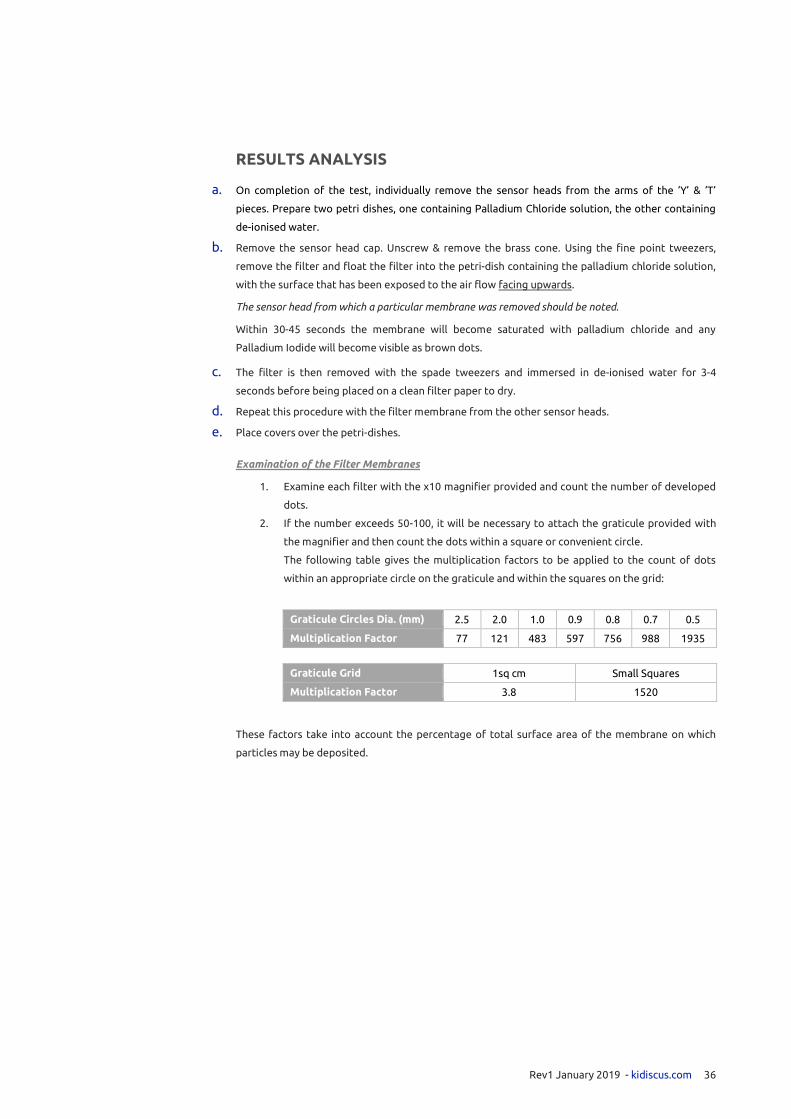
RESULTS ANALYSIS
a. On completion of the test, individually remove the sensor heads from the arms of the ‘Y’ & ‘T’
pieces. Prepare two petri dishes, one containing Palladium Chloride solution, the other containing
de-ionised water.
b. Remove the sensor head cap. Unscrew & remove the brass cone. Using the fine point tweezers,
remove the filter and float the filter into the petri-dish containing the palladium chloride solution,
with the surface that has been exposed to the air flow facing upwards.
The sensor head from which a particular membrane was removed should be noted.
Within 30-45 seconds the membrane will become saturated with palladium chloride and any
Palladium Iodide will become visible as brown dots.
c. The filter is then removed with the spade tweezers and immersed in de-ionised water for 3-4
seconds before being placed on a clean filter paper to dry.
d. Repeat this procedure with the filter membrane from the other sensor heads.
e. Place covers over the petri-dishes.
Examination of the Filter Membranes
1. Examine each filter with the x10 magnifier provided and count the number of developed
dots.
2. If the number exceeds 50-100, it will be necessary to attach the graticule provided with
the magnifier and then count the dots within a square or convenient circle.
The following table gives the multiplication factors to be applied to the count of dots
within an appropriate circle on the graticule and within the squares on the grid:
Graticule Circles Dia. (mm) 2.5 2.0 1.0 0.9 0.8 0.7 0.5
Multiplication Factor 77 121 483 597 756 988 1935
Graticule Grid 1sq cm Small Squares
Multiplication Factor 3.8 1520
These factors take into account the percentage of total surface area of the membrane on which
particles may be deposited.

Rev1 January 2019 - kidiscus.com 37
INTERPRETING RESULTS
For a microbiological safety cabinet to pass the EN standard for aperture/operator protection,
there must be no more than 62 developed dots on any one filter paper.
Dots on any one filter paper and guide to
cabinet performance.
A count of more than 62 dots on any one
filter paper= FAIL.
?= Marginal Pass
KI-DISCUSTM
OPERATOR PROTECTION FACTOR
62 ×105
𝑛 Where 𝑛 = 𝑛𝑢𝑚𝑏𝑒𝑟 𝑜𝑓 𝑑𝑟𝑜𝑝𝑙𝑒𝑡𝑠 𝑐𝑜𝑢𝑛𝑡𝑒𝑑
Multiplied by Graticule Multiplication factor (if appropriate)
𝑛 𝑛 𝑛
0 >6.20 x 10⁶ 22 2.82 x 10⁵ 44 1.41 x 10⁵
1 6.20 x 10⁶ 23 2.70 x 10⁵ 45 1.38 x 10⁵
2 3.10 x 10⁶ 24 2.58 x 10⁵ 46 1.35 x 10⁵
3 2.07 x 10⁶ 25 2.48 x 10⁵ 47 1.32 x 10⁵
4 1.55 x 10⁶ 26 2.39 x 10⁵ 48 1.29 x 10⁵
5 1.24 x 10⁶ 27 2.30 x 10⁵ 49 1.27 x 10⁵
6 1.03 x 10⁶ 28 2.21 x 10⁵ 50 1.24 x 10⁵
7 8.86 x 10⁵ 29 2.14 x 10⁵ 51 1.22 x 10⁵
8 7.75 x 10⁵ 30 2.07 x 10⁵ 52 1.19 x 10⁵
9 6.89 x 10⁵ 31 2.00 x 10⁵ 53 1.17 x 10⁵
10 6.20 x 10⁵ 32 1.94 x 10⁵ 54 1.15 x 10⁵
11 5.64 x 10⁵ 33 1.88 x 10⁵ 55 1.13 x 10⁵
12 5.17 x 10⁵ 34 1.82 x 10⁵ 56 1.11 x 10⁵
13 4.77 x 10⁵ 35 1.77 x 10⁵ 57 1.09 x 10⁵
14 4.43 x 10⁵ 36 1.72 x 10⁵ 58 1.07 x 10⁵
15 4.13 x 10⁵ 37 1.68 x 10⁵ 59 1.05 x 10⁵
16 3.88 x 10⁵ 38 1.63 x 10⁵ 60 1.03 x 10⁵
17 3.65 x 10⁵ 39 1.59 x 10⁵ 61 1.02 x 10⁵
18 3.44 x 10⁵ 40 1.55 x 10⁵ 62 1.00 x 10⁵
19 3.26 x 10⁵ 41 1.51 x 10⁵
20 3.10 x 10⁵ 42 1.47 x 10⁵
21 2.95 x 10⁵ 43 1.44 x 10⁵
Useful Information – Marginal Pass
A marginal pass, although not technically considered a ‘fail’ result, does not generally indicate
satisfactory operation of the cabinet under test. Only a small margin exists between a ‘pass’ and
‘fail’ result. Further tests or different environmental conditions etc. may produce a ‘fail’ result. The
laboratory owner must be advised of marginal results.
Useful Information – Operation Protection Factor
The Operator Protection Factor is defined as the ratio of exposure to airborne contamination
generated on the open bench to the exposure resulting from the same dispersal within the
containment facility (cabinet) under test.
EX
CE
LL
EN
T
GO
OD
GO
OD
F
AIR
FA
IR
MA
RG
INA
L P
AS
S

Rev1 January 2019 - kidiscus.com 38
Alarms
Functional parameters (vacuum generation, disc speed and pump rotation) are continuously
monitored throughout the test. The status indicators should remain permanently green throughout
the test.
Abnormalities in any of these parameters will be detected and an alarm beacon will activate.
The alarm system operates on 2 levels:
Level One - Low Level Error
Low level error detected. Alarm beacon activated. Test allowed to run.
The detected error is of a low level and was successfully rectified within a reasonable period.
The error is unlikely to have adversely affected the quality of the test. The alarm may be reset
manually and the test allowed to continue at the discretion of the operator.
Useful Information
NB.: If a level one error occurs more than once during the test procedure, it is recommended to stop the
test and re-start the test. Multiple level one errors may have a cumulative affect which may affect the
accuracy of a test.
Level Two - High level error
High level error detected. Alarm beacon activated. Test automatically stopped.
The detected error is of a high level and could not be rectified within a reasonable period.
The error is possibly of a magnitude sufficient to adversely affect the quality of the test. The test is
automatically stopped. The alarm may be reset following the test shut down. The test is not
allowed to continue. A new test must be performed.
Please see the ‘Troubleshooting Guide’ for assistance, should the alarm beacon activate.
The test may be stopped at any time by touching the ‘Abort’ button.
An ‘emergency stop’ may also be performed by switching off the power using the illuminated green
rocker switch on the top panel.

Rev1 January 2019 - kidiscus.com 39
TROUBLE SHOOTING AND ALARM FUNCTIONS
The machine has a comprehensive error detection and diagnosis system.
The alarm sounds when an error is detected. The ‘alarm’ symbol will flash on the screen. The beacon
will flash on the top panel.
ALARM RESET
An alarm screen is shown below:
Touch the flashing alarm symbol to access the Alarm Status screen.
Touch ‘Reset Alarm’ to silence the alarm and extinguish the alarm lamp. It may be necessary to do
this more than once for particular faults. Press ‘F4’ to return to the previous screen.
Touch ‘Reset Alarm’
Touch Alarm Symbol
Rev1 January 2019 - kidiscus.com 40
TROUBLESHOOTING
Vacuum pressure fault: Check all sensor heads are securely fitted and filter membranes loaded in
each head.
Spray generator fault: Check spray generator cable is securely connected. Check drive belt.
PM001 Clamp fault: Ensure peristaltic pump lid is closed.
No operation. Power switch Illuminated. No screen display. The internal temperature may be too
high. If possible, move machine to a cool, dry, ventilated area. Leave cabinet front door open. Re-
attempt use after 30 minutes. If problem persists, contact CTS.
No automatic test function. The machine may be in ‘Manual’ mode. Enter ‘Manual Control’ screen.
The indication mode is shown in the bottom left corner. This must display ‘Auto’. If it displays
‘Manual’, the machine will not perform an automatic test. Touch the button so that ‘Auto’ is
displayed.
Press ‘F4’ to return to the main screen.
Contact CTS for further fault assistance.

Rev1 January 2019 - kidiscus.com 41
Maintenance of KI-DISCUS TM System
No regular maintenance is required other than scrupulous attention to keeping all components
clean. As soon as the day’s session of tests is completed, the following procedure should be
followed:
1. Clean the laboratory stand, the aerosol generator, artificial arm sections and the sensor heads
using a tissue or cloth lightly moistened with water. Do not use abrasive materials or
aggressive cleaning chemicals on any part of KI-DISCUSTM
. Use of these materials may
damage KI-DISCUSTM
and will not be covered by the warranty.
2. Remove the sensor head covers and the brass cones, clean the insides of the covers, the brass
cones and the filter membrane holders with a lightly moistened tissue. Replace the cones and the
covers.
3. Thoroughly wash, rinse and dry the Petri-dishes and the tweezers.
4. Gentle foam cleansers may be used to clean the cabinet.
5. Clean the touchscreen and keyboard membrane.
Use a cleaning cloth dampened with a cleaning agent. Only use water with little liquid soap or a
reputable screen cleaning foam. Never use compress air, steam jet air ejectors, aggressive
chemicals or scouring agents.
6. It is recommended to flush the silicone tubing through with water at the end of a day’s testing.
This should prevent the formation of Potassium Iodide crystals within the tubing.
Useful Information
Potassium Iodide crystal formation, within tubing may impede the flow of the solution during tests.
This may affect the accuracy of results.
Information - Cleaning
In addition to cleaning the KI-DISCUS TM
system after use, the walls and base of the Cabinet that has
been tested should be cleaned.
Calibration
KI-DISCUS TM
is calibrated to the manufacturer specifications prior to shipping.
The calibration period is valid for one year.
Annual calibration is required to ensure optimum performance.
KIDISCUSTM
system should be only calibrated by engineers appointed by CTS Europe Ltd.
For further information contact CTS or email [email protected]

Rev1 January 2019 - kidiscus.com 42
Technical Specification
Model Ref KI-DISCUS TM MK 3
Manufacturer CTS Europe Ltd - containment-technology.co.uk
Weight 39.5 Kg
POWER REQUIREMENTS
Voltage 100v – 120v AC / 220v-240v AC 50-60Hz
ENVIRONMENTAL OPERATING RANGE
Temperature 15°C to 25° C
Humidity 5%-80% RH

Rev1 January 2019 - kidiscus.com 43
Spares List
REF DESCRIPTION
4248805 Millipore Filter Membrane 1" Dia (Box of 100)
4253813 Liquid 500ml bottle Palladium Chloride L.D.P.E.
4253812 Liquid 500ml bottle Potassium Iodide L.D.P.E.
4253814 Liquid 500ml bottle Distilled water L.D.P.E.
4253811 Liquid 5L bottle Potassium Iodide L.D.P.E.
3/730001 Reservoir Bottle Integral 250 ml
3/730002 Reservoir Bottle Holder Snap Hook Clip-On
3/730006 Reservoir Bottle Tip
3/730003 RS232 printer
3/730004 Printer plug cable
3/730005 Printer Paper Roll
3263802 Tool 4 thou gauge
3268107 Bar tommy
4263819 Tool Alan key
3/730006 Tool distance piece - Complete
4263810 Millipore Tweezers
4263817 Tool stainless extra fine curved tweezers
4263820 Tool precision tweezers flat rounded point
4263811 MAG6 Pocket Magnifier Tool
4263813 Tool - Graticule
4263814 25ml Measuring Cylinder
4263812 Petri Dish with Cover
4266803 O Ring 1 5/8" O/D (020) - VacuumTube
4266804 O Ring 1" O/D (036) Sensor head Female
4266806 O Ring 2 1/2" O/D (029) Sensor head Male
3/731000 Vacuum Gauge Assembly - Complete
3/731001 Vacuum Gauge Rubber Cover
3/731002 Vacuum Gauge 50 mm
3/733000 Aerosol Generator - Complete
3/733100 Bearing Assembly - Complete
3/733200 Generator Hub and Disc Assembly - Complete
3/733201 Spinning Disc
3/733202 Generator Hub
3/733306 Nozzle Nebuliser
3/733308 Aerosol Generator Belt drive
3/733425 Locking Screw Assembly Long - Complete
3/432000 Locking Screw Assembly Short - Complete
3/734000 Sensor Head - Complete
3/734214 Sensor Cone Nozzle Mounting Plate Assembly-Complete
3/734215 Sensor Cone - Brass
3/450001 Elec/Con right angle socket Mains lead
3/440006 KI-DISCUS TM Bag
3/450000 KI-DISCUS TM MK 3 Handbook
3/440007 Cabinet Shipment Packaging
3/720001 Tool Box Shipment Packaging
Please contact [email protected] for all KI-DISCUSTM
MK3 parts availability and Pricing
Health & Safety Data Sheets – Current MSDS are available on request.

Rev1 January 2019 - kidiscus.com 44
Product Decommissioning and Disposal
In accordance to the WEEE directive 2012/19/EU (waste electrical and electronic equipment)
At the end of the useful life of your KI-DISCUSTM
MK 3, we as the manufacturer will accept the
applicable electronic modules back to our facility and will dispose of these in accordance to the
above directive.
Product Warranty Statement
Thank you for purchasing from CTS Europe Ltd.
This Limited warranty applies to physical goods, and only for physical goods purchased from CTS
Europe Ltd.
The Limited warranty covers any defects in function, material or workmanship under normal use
during warranty period which is 6 months from the date of commissioning by CTS approved
engineer
CTS warrants to the original purchaser, with proof of purchase, that its delivered products shall be
free from defects in material and workmanship under normal use for a period of 6 months, from
date of
During the warranty period, we will repair or replace, at no charge, products or parts of a product
that prove defective due to because of improper material workmanship or electrical component
failure.
This assumes a system under normal use and maintained with manufacturers recommended spares.
A CTS product that is repaired under warranty will receive a new 6 month warranty commencing on
the date of repair.
This limited warranty does not cover any problem that is caused by:
Conditions, malfunctions or damage which is not a result of defects in material or
workmanship.
Engineer travel costs to customer site to carry out an on – site repair
If you have any concerns regarding this product, Please contact us on [email protected]

Rev1 January 2019 - kidiscus.com 45
Declaration of Conformity
Manufacture CTS Europe Ltd, 14 Ordnance Court, Ackworth Road,
Portsmouth, PO3 5RZ
Product MK3 KI-DISCUS TM Test Equipment
The above named product conforms to the requirements of the following European Directives:
2006/42/EC Machinery Directive
LVD 2014/35/EU Low Voltage Directive
2014/30/EU EMC Directive
Conformity with the requirements of the directives is testified by adherence to the relevant parts
of the following harmoised standards:
BS EN 61010-1:2010 Safety requirements for electrical equipment
BS EN ISO 12100:2010 Safety of machinery- General principles
BS EN 61326-1:2013 General EMC requirements for measurement,
control & laboratory use equipment- Emissions
and Immunity requirements.
BS EN 61000-3-2:2014 Limits for mains harmonics
BS EN 61000-3-3:2013 Limits for mains voltage fluctuations & flicker
Sean Codling
For and on behalf of: CTS Europe Ltd
Date: 1st Dec 2018


kidiscus.com [email protected] +44(0)2392 695521
KI-DISCUSTM is a trade Mark registered in the United Kingdom and other countries
Visit kidiscus.com