Embed Size (px)
Citation preview

-1-
KGS-1060
KGS-1060-HP
Industrial Managed
10-Port Gigabit Ethernet Switches
with 2 Dual-speed SFP Slots and 4 PoE PSE Ports
Firmware Rev1.05 up
User’s Manual
DOC.170802

-2-
99B(C) 2014-2015 KTI Networks Inc.
All rights reserved. No part of this documentation may be reproduced in any form or by any means or used to
make any directive work (such as translation or transformation) without permission from KTI Networks Inc.
KTI Networks Inc. reserves the right to revise this documentation and to make changes in content from time to
time without obligation on the part of KTI Networks Inc. to provide notification of such revision or change.
For more information, contact:
United States KTI Networks Inc.
P.O. BOX 631008
Houston, Texas 77263-1008
Phone: 713-2663891
Fax: 713-2663893
E-mail: [email protected]
URL: http://www.ktinet.com/
International Fax: 886-2-26983873
E-mail: [email protected]
URL: http://www.ktinet.com.tw/

-3-
The information contained in this document is subject to change without prior notice.
Copyright © All Rights Reserved.
112TRADEMARKS
Ethernet is a registered trademark of Xerox Corp.
FCC NOTICE
This device complies with Part 15 of the FCC Rules. Operation is subject to the following two conditions: (1)
This device may not cause harmful interference, and (2) This device must accept any interference received,
including the interference that may cause undesired operation.
CE NOTICE
Marking by the symbol indicates compliance of this equipment to the EMC directive of the European
Community. Such marking is indicative that this equipment meets or exceeds the following technical
standards:
EMC Class A
EN 61000-6-4:2007/A1:2011
EN 61000-3-2:2006/A1:2009/A2:2009
EN 61000-3-3:2008
EN 61000-6-2:2005
IEC 61000-4-2:2008
IEC 61000-4-3:2010
IEC 61000-4-4:2012
IEC 61000-4-5:2005
IEC 61000-4-6:2008
IEC 61000-4-8:2009
IEC 61000-4-11:2004
VCCI-A Notice
-4-
Table of Contents
0B1. Introduction ...................................................................................................................................................... 5
1.1 Features ............................................................................................................................... 6
1.2 Product Panels ..................................................................................................................... 7
1.3 LED Indicators ...................................................................................................................... 8
1.4 Specifications ....................................................................................................................... 8
1B2. Installation ...................................................................................................................................................... 11
10B2.1 Unpacking .......................................................................................................................... 11
2.2 Safety Cautions .................................................................................................................. 11
12B2.3 DIN-Rail Mounting .............................................................................................................. 12
13B2.4 Panel Mounting .................................................................................................................. 14
14B2.5 Applying Power .................................................................................................................. 16
15B2.6 Alarm Relay Output ............................................................................................................ 18
2.7 Powered via PoE over Cat.5 (KGS-1060) ........................................................................... 18
2.8 Reset Button ...................................................................................................................... 19
2.9 Making UTP Connections ................................................................................................... 20
2.10 Making Fiber Connection .................................................................................................. 21
2.11 Making PoE PSE Connections (KGS-1060-HP) ............................................................... 23
1306B2.12 LED Indication .................................................................................................................. 24
20B2.13 Making Console Connection ............................................................................................. 24
3. Manage the Switch ........................................................................................................................................ 26
3.1 IP Address & Password ...................................................................................................... 26
3.2 Configuring IP Address & Password via console and telnet ................................................ 26
3.3 Configuring IP Address via Web Interface .......................................................................... 27
3.4 Reference Manuals for Web, Console, Telnet Management ............................................... 29
3.5 Configuration for SNMP Management ................................................................................ 30
3.6 SNMP MIBs........................................................................................................................ 31
4. Redundant Ring Applications ...................................................................................................................... 33
4.1 Auto Multi-Ring Technology ............................................................................................... 33
4.2 Redundant Ring Applications with industrial standard RSTP protocol ................................ 34

-5-
0B1. Introduction
131The KGS-1060 series is an 10-portt industrial managed Gigabit Ethernet switch which is featured with the
following switched ports:
Eight 10/100/1000Mbps Gigabit copper ports
Two dual-speed SFP slots for 100Base-FX 1000Base-X
Model Definitions
Model Copper
ports
SFP slots PoE PSE
function
Power via
DC input
Powered via
PoE capable
Software
managed
KGS-1060-HP 8 2 dual-speed 4 PSE ports -
KGS-1060 8 2 dual-speed -

-6-
1.1 Features
Eight 10/100/1000Mbps RJ-45 and two dual-speed SFP slots
All copper ports support auto-negotiation and auto-MDI/MDI-X detection.
Two SFP slots support dual speed for 100BASE-FX and 1000BASE-X SFP transceivers.
Full wire speed forwarding
Supports 802.3x flow control for full-duplex and backpressure for half-duplex
Port link aggregation function with LACP support
Supports SFP with Digital Diagnostic Monitoring (DDM)
Alternatively powered via PoE if direct DC power not available
Optional four 802.3at-compliant PoE+ PSE ports
SNMP private MIB for DDM status, reboot, TFTP firmware update (MIB file Rev1.05 or up)
Optical Power Alarm (OPA) function
Auto Laser Shutdown (ALS) function (supported in H/W Ver.E up)
Management:
- HTTP/HTTPS/SSHv2/CLI telnet/CLI console/SNMP v1/v2c/v3/RMON
- DHCP/DHCPv6 client, DHCP relay, DNS client, NTPv4
- IPv6 support, System Syslog, Configuration down/upload, Software upload
Security:
- NAS, 802.1X, MAC-based/Web/CLI authentication
- IP MAC binding, TACACS+, IP source guard
Layer 2:
- QoS, 802.1Q/MAC-based/Protocol-based/Private/IP subnet VLAN, Port Isolation
- Storm control for UC/MC/BC packets, Static MAC configuration
- IGMP v2/v3 snooping, MLD v1/v2 snooping, DHCP snooping
- Multiple Spanning Tree - MSTP. RSTP, STP
Auto Multi-Ring (KAMR) Technology:
- Fast failover response time, Auto recovery when failure is repaired
- Supports up to five redundant rings, Works with RSTP network

-7-
1.2 Product Panels
The following figure illustrates the front panel and rear panel of the switch:
KGS-1060-HP Front panel
KGS-1060 Front panel

-8-
154BUp panel
1.3 LED Indicators
LED Function
PWR Power status
Mgt. Management status
Port 1~ 8 SPEED LEDs Speed & PoE status
Port 1~ 8 LINK LEDs Link & activity status
SFP 9, 10 LED Speed & link & activity status of SFP port
1.4 Specifications
10/100/1000 Copper Ports (Port 1 ~ Port 8)
Compliance IEEE 802.3 10Base-T, IEEE 802.3u 100Base-TX, IEEE 802.3u 1000Base-T
Connectors Shielded RJ-45 jacks
Pin assignments Auto MDI/MDI-X detection
Configuration Auto-negotiation or software control
Transmission rate 10Mbps, 100Mbps, 1000Mbps
Duplex support Full/Half duplex
Network cable Cat.5 UTP
Dual-speed SFP Slots (Port 9, Port 10)
Compliance IEEE 802.3u 100Base-FX
IEEE 802.3z 1000Base-SX/LX (mini-GBIC)
Connectors SFP for optional SFP type fiber transceivers
Configuration Auto 1000Mbps, Full duplex
Forced 100Mbps, Full duplex
Transmission rate 100Mbps and 1000Mbps
Network cables MMF 50/125 60/125, SMF 9/125
Eye safety IEC 825 compliant

-9-
Console Port
Interface RS-232, DTE type
Connector Shielded RJ-45
Switch Functions
MAC Addresses Table 8K entries
Forwarding & filtering Non-blocking, full wire speed
Switching technology Store and forward
Maximum packet length 9.6K bytes
IP Multicast groups 8192 supported
Flow control IEEE 802.3x pause frame base for full duplex operation
Back pressure for half duplex operation
Power over Ethernet PSE Function (KGS-1060-HP)
PSE Ports Port 1 ~ Port 4
Power output pins Positive of power voltage: pin 4, 5
Negative of power voltage: pin 7, 8
Standard IEEE 802.3at
Classification PD Class 0 ~ 4 detection
Power Delivery 30W max. (per port) at port output for Cat.5 distance up to 100 meters
Protection Under voltage protection
Over voltage protection
Over current detection
Powered via Power over Ethernet (KGS-1060)
PD Port Port 2
PoE Standard IEEE 802.3af PoE PD (Powered Device)
PSE Support IEEE 802.3af & 802.3at PSE
Power Classification Class 3
Input Voltage (Vpoe) 36 ~ 57VDC via Cat.5
Power reception pins Positive of PoE power voltage: pin 1,2,4,5
Negative of power voltage: pin 3,6,7,8
Terminal Block Connector

-10-
DC power input Screwed euro terminal block: 2 pairs of +/- contacts
Operating Input Voltages +7 ~ +60VDC (General applications)
+45 ~ +57VDC (PoE applications)
Power consumption 9W max. (Full load with no PoE support)
130W max. (Full load with 4 PoE max. output)
Alarm relay output 2 terminal contacts AR+/AR- (30VDC/1A max. or 120VAC/0.5A max.)
Alarm events Power failure, Specific port link fault (software configured), OPA
* Warning: The -48VDC power supply is not supported.
856BUMechanical
Dimension (base) 140 x 106 x 42 mm (HxDxW)
Housing Enclosed metal with no fan
Mounting Din-rail mounting, Panel mounting (optional)
860BUEnvironmental
Operating Temperature Typical -30℃ ~ +70℃*
Storage Temperature -40℃ ~ +85℃
Relative Humidity 5% ~ 90% non-condensing
* +60℃ ~ +70℃ with 1m/s air flow
864BUElectrical Approvals
FCC Part 15 rule Class A
CE EMC, CISPR11 Class A
Safety / LVD IEC 60950-1
-11-
1B2. Installation
10B2.1 Unpacking
The product package contains:
The switch unit
One product CD-ROM
One console cable
2.2 Safety Cautions
To reduce the risk of bodily injury, electrical shock, fire, and damage to the product, observe the
following precautions.
Do not service any product except as explained in your system documentation.
Opening or removing covers may expose you to electrical shock.
Only a trained service technician should service components inside these compartments.
If any of the following conditions occur, unplug the product from the electrical outlet and replace
the part or contact your trained service provider:
The power cable, extension cable, or plug is damaged.
An object has fallen into the product.
The product has been exposed to water.
The product has been dropped or damaged.
The product does not operate correctly when you follow the operating instructions.
Do not push any objects into the openings of your system. Doing so can cause fire or electric
shock by shorting out interior components.
Operate the product only from the type of external power source indicated on the electrical ratings
label. If you are not sure of the type of power source required, consult your service provider or
local power company.
-12-
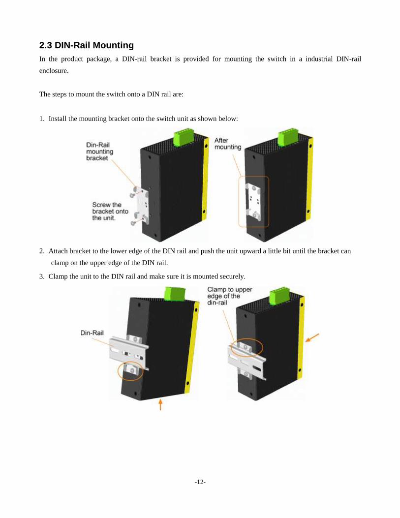
12B2.3 DIN-Rail Mounting
171BIn the product package, a DIN-rail bracket is provided for mounting the switch in a industrial DIN-rail
enclosure.
172BThe steps to mount the switch onto a DIN rail are:
1. 1287BInstall the mounting bracket onto the switch unit as shown below:
2. 1288BAttach bracket to the lower edge of the DIN rail and push the unit upward a little bit until the bracket can
clamp on the upper edge of the DIN rail.
3. 1289BClamp the unit to the DIN rail and make sure it is mounted securely.

-13-
Dimensions:
-14-
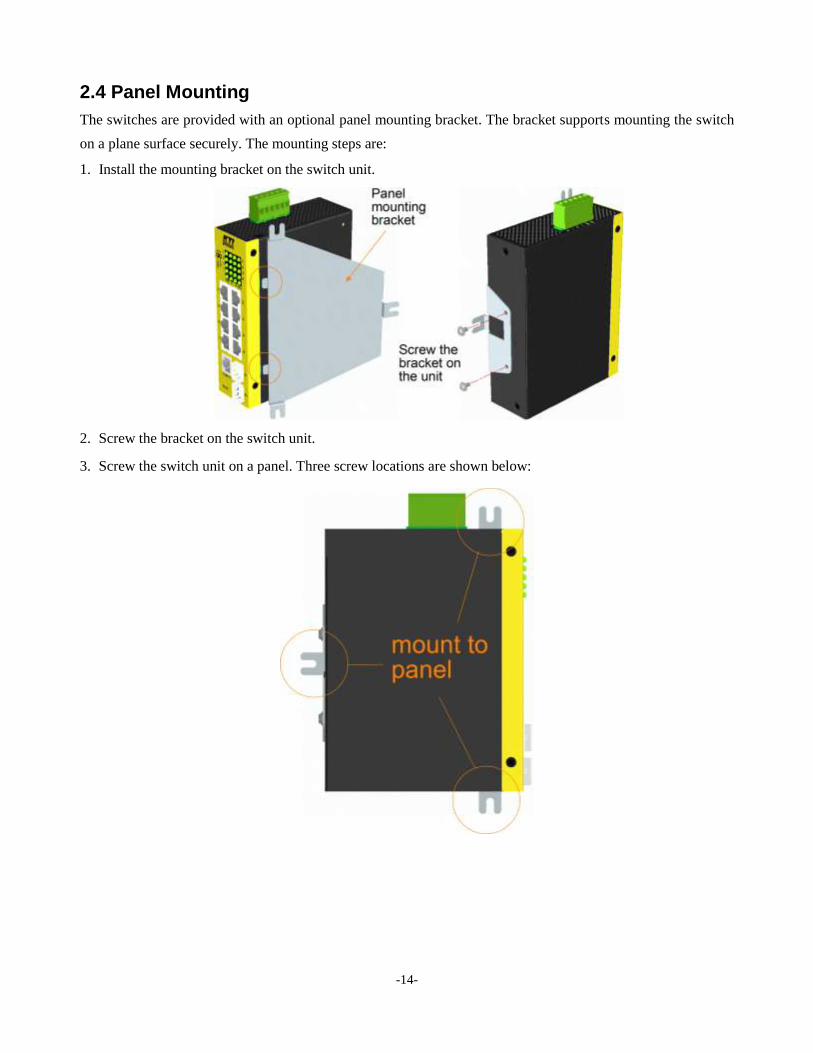
13B2.4 Panel Mounting
173BThe switches are provided with an optional panel mounting bracket. The bracket supports mounting the switch
on a plane surface securely. The mounting steps are:
1. 1290BInstall the mounting bracket on the switch unit.
2. 1291BScrew the bracket on the switch unit.
3. 1292BScrew the switch unit on a panel. Three screw locations are shown below:
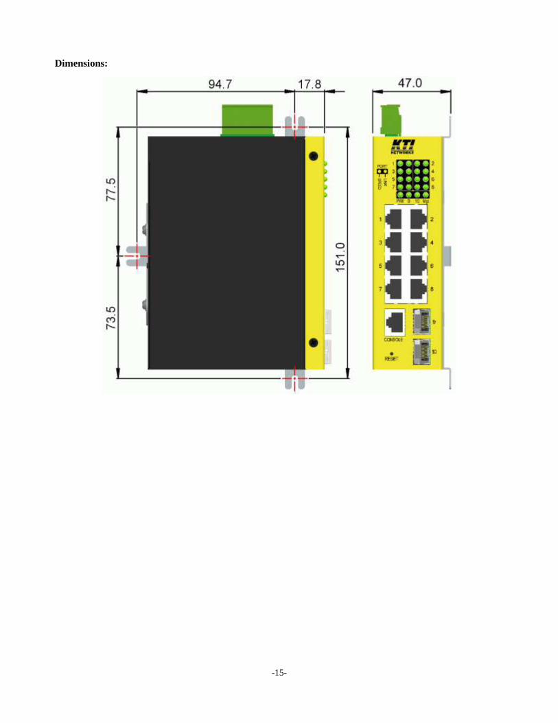
-15-
Dimensions:

-16-
14B2.5 Applying Power
Pin Assignments of the terminal block connector
Vdc Positive () input terminal
Vdc Negative () input terminal
Vdc Positive () input terminal
Vdc Negative () input terminal
AR+ Alarm relay output positive () terminal
AR Alarm relay output negative () terminal
Any of the Vdc+/Vdc- pairs can be used to receive DC power from an external power system. Or, one can be
used to deliver the power received on another to next switch in cascading way.
Vdc Input specifications
Applications Power per PSE port DC working voltage
General - +7V ~ +60VDC
PoE 15.4W max. +45V ~ +57VDC (Typical 48V)
High power PoE (PoE+) 30W max. +45V ~ +57VDC (+52V up for 30W)
WARNING: The -48VDC power supply is not supported.
Caution:
Do not apply direct DC IN power and PoE power at the same time.
Unplug DC IN when PoE power is connected.
Disconnect PoE power when DC IN is used.

-17-
Three 2P terminal plugs are provided together with the switch. Two of the three plugs are used for Vdc
interfaces respectively. The plug is shown below:
184BPower wires : 24 ~ 12AWG (IEC 0.5~2.5mm2)
Install the power source wires with the plug properly. Then, plug in input contacts. If cascading the power to
next switch device is needed, install the power wires and plug for another switch. Then, use another Vdc
contacts.
Note:
1. Only up to four device units can be cascaded to receive power from one main power input source.
2. The maximal length of the power wire is 1 meter.
-18-
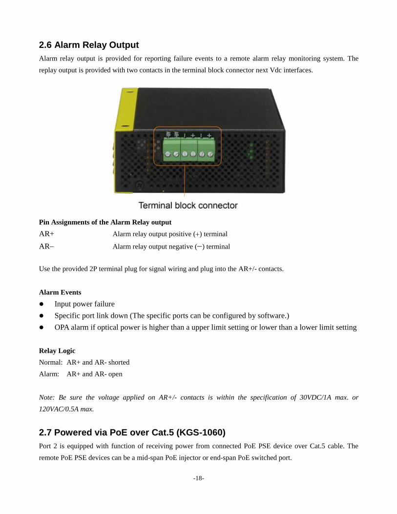
15B2.6 Alarm Relay Output
Alarm relay output is provided for reporting failure events to a remote alarm relay monitoring system. The
replay output is provided with two contacts in the terminal block connector next Vdc interfaces.
Pin Assignments of the Alarm Relay output
AR+ Alarm relay output positive () terminal
AR Alarm relay output negative () terminal
Use the provided 2P terminal plug for signal wiring and plug into the AR+/- contacts.
Alarm Events
Input power failure
Specific port link down (The specific ports can be configured by software.)
OPA alarm if optical power is higher than a upper limit setting or lower than a lower limit setting
Relay Logic
198BNormal: AR+ and AR- shorted
199BAlarm: AR+ and AR- open
200BNote: Be sure the voltage applied on AR+/- contacts is within the specification of 30VDC/1A max. or
120VAC/0.5A max.
2.7 Powered via PoE over Cat.5 (KGS-1060)
Port 2 is equipped with function of receiving power from connected PoE PSE device over Cat.5 cable. The
remote PoE PSE devices can be a mid-span PoE injector or end-span PoE switched port.
-19-
The switches can support the following PSE:
802.3af compliant PSE (Typical, Type 1 PSE)
Possible voltages received: +36 ~ +57VDC
802.3at compliant PSE (High power PoE, Type 2 PSE)
Possible voltages received: +42.5 ~ +57VDC
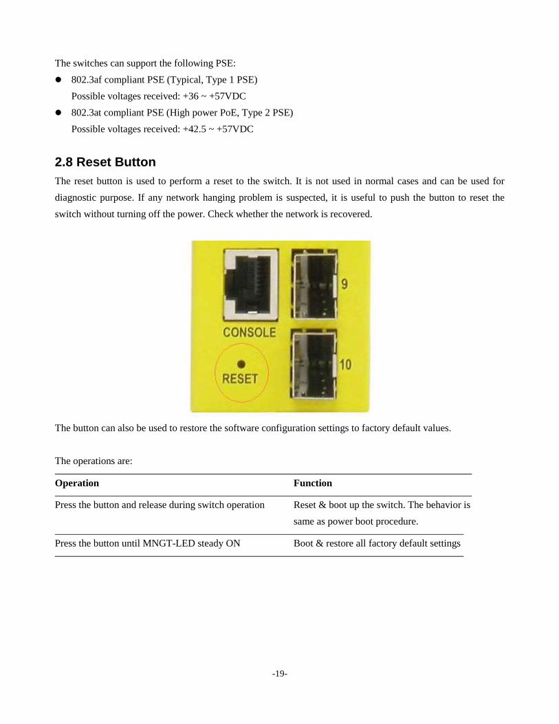
2.8 Reset Button
The reset button is used to perform a reset to the switch. It is not used in normal cases and can be used for
diagnostic purpose. If any network hanging problem is suspected, it is useful to push the button to reset the
switch without turning off the power. Check whether the network is recovered.
The button can also be used to restore the software configuration settings to factory default values.
The operations are:
Operation Function
Press the button and release during switch operation Reset & boot up the switch. The behavior is
same as power boot procedure.
Press the button until MNGT-LED steady ON Boot & restore all factory default settings
-20-
2.9 Making UTP Connections
The 10/100/1000 RJ-45 copper ports support the following connection types and distances:
Network Cables
10BASE-T: 2-pair UTP Cat. 3, 4, 5 , EIA/TIA-568B 100-ohm
100BASE-TX: 2-pair UTP Cat. 5, EIA/TIA-568B 100-ohm
1000BASE-T: 4-pair UTP Cat. 5 or higher (Cat.5e is recommended), EIA/TIA-568B 100-ohm
Link distance: Up to 100 meters for all above
Auto MDI/MDI-X Function
This function allows the port to auto-detect the twisted-pair signals and adapts itself to form a valid MDI to
MDI-X connection with the remote connected device automatically. No matter a straight through cable or
crossover cable is connected, the ports can sense the receiving pair automatically and configure itself to match
the rule for MDI to MDI-X connection. It simplifies the cable installation.
Auto-negotiation Function
The ports are featured with auto-negotiation function and full capability to support connection to any Ethernet
devices. The port performs a negotiation process for the speed and duplex configuration with the connected
device automatically when each time a link is being established. If the connected device is also
auto-negotiation capable, both devices will come out the best configuration after negotiation process. If the
connected device is incapable in auto-negotiation, the switch will sense the speed and use half duplex for the
connection.
Port Configuration Management
For making proper connection to an auto-negotiation incapable device, it is suggested to use port control
function via software management to set forced mode and specify speed and duplex mode which match the
configuration used by the connected device.
-21-
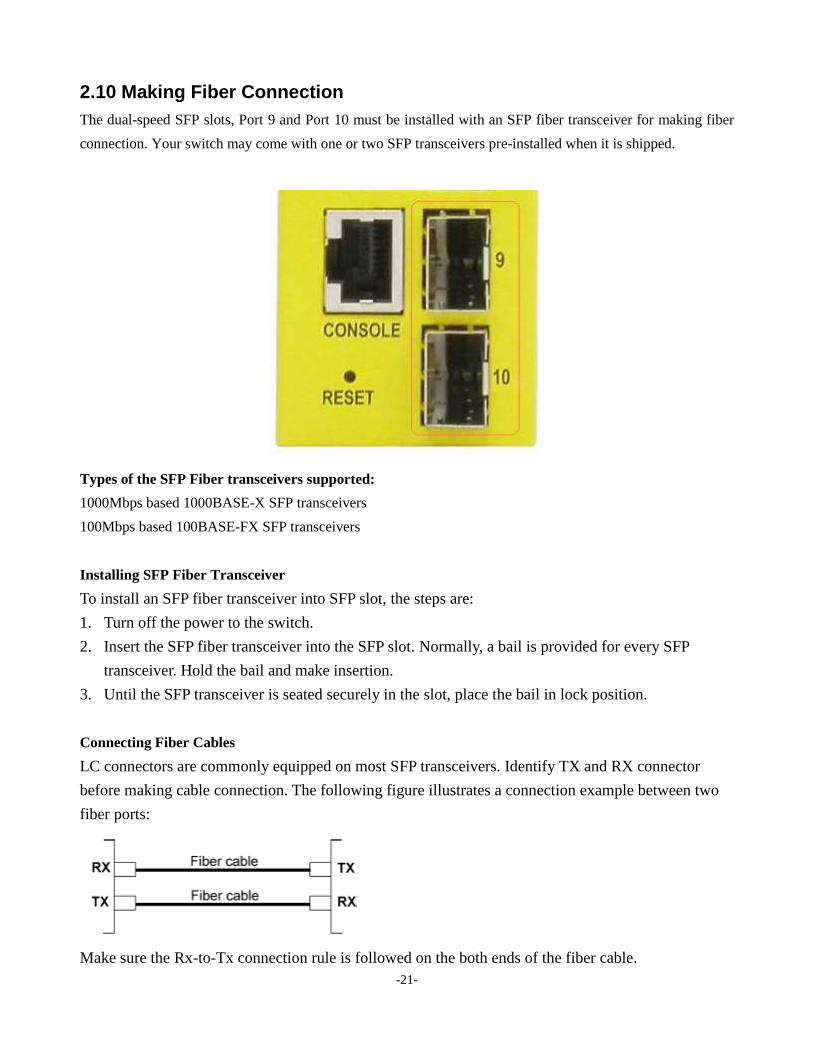
2.10 Making Fiber Connection
The dual-speed SFP slots, Port 9 and Port 10 must be installed with an SFP fiber transceiver for making fiber
connection. Your switch may come with one or two SFP transceivers pre-installed when it is shipped.
Types of the SFP Fiber transceivers supported:
1000Mbps based 1000BASE-X SFP transceivers
100Mbps based 100BASE-FX SFP transceivers
Installing SFP Fiber Transceiver
217BTo install an SFP fiber transceiver into SFP slot, the steps are:
1. Turn off the power to the switch.
2. Insert the SFP fiber transceiver into the SFP slot. Normally, a bail is provided for every SFP
transceiver. Hold the bail and make insertion.
3. Until the SFP transceiver is seated securely in the slot, place the bail in lock position.
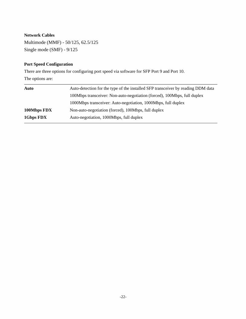
Connecting Fiber Cables
LC connectors are commonly equipped on most SFP transceivers. Identify TX and RX connector
before making cable connection. The following figure illustrates a connection example between two
fiber ports:
Make sure the Rx-to-Tx connection rule is followed on the both ends of the fiber cable.
-22-
Network Cables
Multimode (MMF) - 50/125, 62.5/125
Single mode (SMF) - 9/125
Port Speed Configuration
There are three options for configuring port speed via software for SFP Port 9 and Port 10.
The options are:
Auto Auto-detection for the type of the installed SFP transceiver by reading DDM data
100Mbps transceiver: Non-auto-negotiation (forced), 100Mbps, full duplex
1000Mbps transceiver: Auto-negotiation, 1000Mbps, full duplex
100Mbps FDX Non-auto-negotiation (forced), 100Mbps, full duplex
1Gbps FDX Auto-negotiation, 1000Mbps, full duplex
-23-
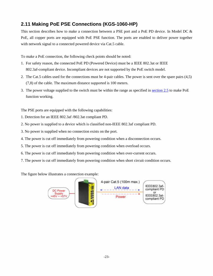
2.11 Making PoE PSE Connections (KGS-1060-HP)
This section describes how to make a connection between a PSE port and a PoE PD device. In Model DC &
PoE, all copper ports are equipped with PoE PSE function. The ports are enabled to deliver power together
with network signal to a connected powered device via Cat.5 cable.
To make a PoE connection, the following check points should be noted:
1. For safety reason, the connected PoE PD (Powered Device) must be a IEEE 802.3at or IEEE
802.3af-compliant device. Incompliant devices are not supported by the PoE switch model.
2. The Cat.5 cables used for the connections must be 4-pair cables. The power is sent over the spare pairs (4,5)
(7,8) of the cable. The maximum distance supported is 100 meters.
3. The power voltage supplied to the switch must be within the range as specified in section 2.5 to make PoE
function working.
The PSE ports are equipped with the following capabilities:
1. Detection for an IEEE 802.3af /802.3at compliant PD.
2. No power is supplied to a device which is classified non-IEEE 802.3af compliant PD.
3. No power is supplied when no connection exists on the port.
4. The power is cut off immediately from powering condition when a disconnection occurs.
5. The power is cut off immediately from powering condition when overload occurs.
6. The power is cut off immediately from powering condition when over-current occurs.
7. The power is cut off immediately from powering condition when short circuit condition occurs.
237BThe figure below illustrates a connection example:
-24-
1306B2.12 LED Indication
LED Function Color State Interpretation
PWR Power status Green ON The power is supplied to the switch.
OFF The power is not supplied to the switch.
Mgt. Management status Green OFF The switch is in initialization and diagnostics.
Yellow BLINK Initialization completed with diagnostic error
or system error found during normal operation
Green ON Initialization completed with no error
Port 1 ~ Port 8
SPEED_LED Port speed status Green ON Speed is 1000Mbps.
Yellow ON Speed is 10Mbps or 100Mbps.
BLINK PoE power is on.
LINK_LED Port link status Green ON Port link is established. (No traffic)
Green BLINK Port link is up and there is traffic.
OFF Port link is down.
Port 9 ~ Port 10
Speed _LED Port speed/link status Green ON A 1000Mbps link is established.
Yellow ON A 100Mbps link is established.
BLINK Activity status
OFF Port link is down.
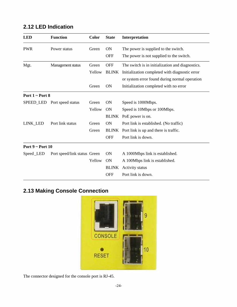
20B2.13 Making Console Connection
1307BThe connector designed for the console port is RJ-45.

-25-
Pin Assignments
Pin RS-232 signals IN/OUT
256B1,2,7,8 NC
3 RxD IN
6 TxD OUT
4,5 GND
Baud Rate information
Baud rate - 115200
Data bits - 8
Parity - None
Stop bit - 1
Flow control – None
-26-
3. Manage the Switch
The switch provides the following methods to configure and monitor the switch as follows:
Making out of band telnet CLI management via the console port
Making in-band management via telnet CLI over TCP/IP network
Making in-band management via web interface over TCP/IP network
Making in-band SNMP management over TCP/IP network
3.1 IP Address & Password
The IP Address is an identification of the switch in a TCP/IP network. Each switch should be designated a new
and unique IP address in the network. The switch is shipped with the following factory default settings for
software management:
Default IP address of the switch: 192.168.0.2 / 255.255.255.0
The switch uses local authentication instead of RADIUS authentication with factory defaults.
Fixed Username: admin
Default password:
No password is required with factory default. However, the password is used for local authentication in
accessing to the switch via console, telnet and Http web-based interface. For security reason, it is
recommended to change the default settings for the switch before deploying it to your network.
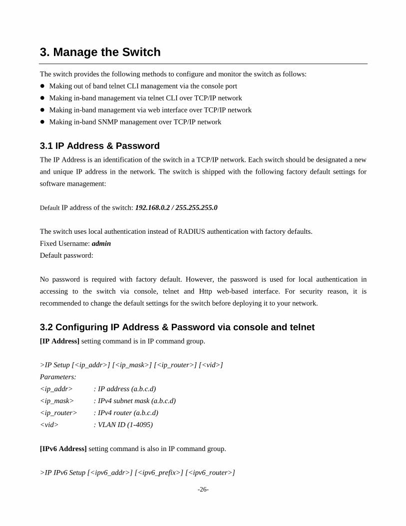
3.2 Configuring IP Address & Password via console and telnet
[IP Address] setting command is in IP command group.
>IP Setup [<ip_addr>] [<ip_mask>] [<ip_router>] [<vid>]
Parameters:
<ip_addr> : IP address (a.b.c.d)
<ip_mask> : IPv4 subnet mask (a.b.c.d)
<ip_router> : IPv4 router (a.b.c.d)
<vid> : VLAN ID (1-4095)
[IPv6 Address] setting command is also in IP command group.
>IP IPv6 Setup [<ipv6_addr>] [<ipv6_prefix>] [<ipv6_router>]
-27-
Parameters:
<ipv6_addr> : IPv6 address is in 128-bit records represented as eight fields of up to four hexadecimal
digits with a colon separates each field (:).
<ipv6_prefix> : IPv6 subnet mask
<ipv6_router> : IPv6 router
[Password] setting command is also in Security/Switch/Users command group.
Security Switch Users Configuration
Security Switch Users Add <user_name> <password> <privilege_level>
Security Switch Users Delete <user_name>
Refer to “Operation manual for telnet and console management”.
3.3 Configuring IP Address via Web Interface
Start Web Browser
Start your browser software and enter the default IP address of the switch unit to which you want to connect.
The IP address is used as URL for the browser software to search the device.
URL: http:/192.168.0.2/
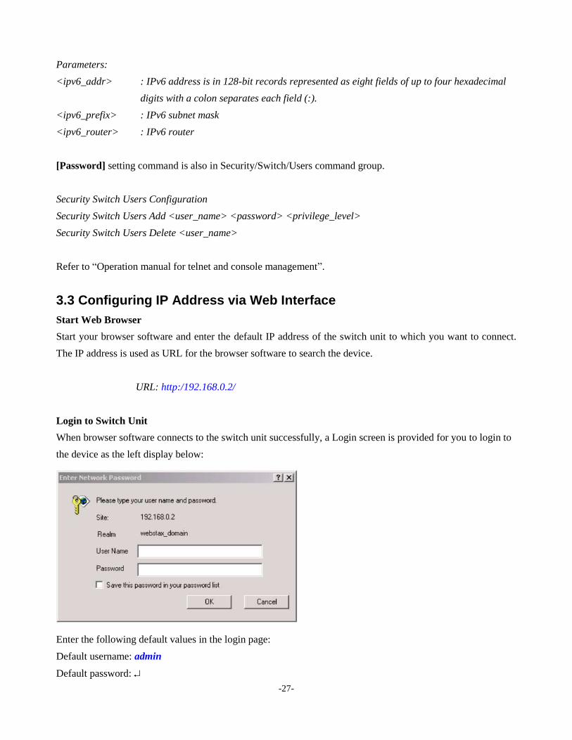
Login to Switch Unit
When browser software connects to the switch unit successfully, a Login screen is provided for you to login to
the device as the left display below:
Enter the following default values in the login page:
Default username: admin
Default password:

-28-
No password is required.
Click OK to login into the switch.
Web Page after a Successful Login
Select [Configuration] -> [System] -> [IP] to configure IP address
-29-
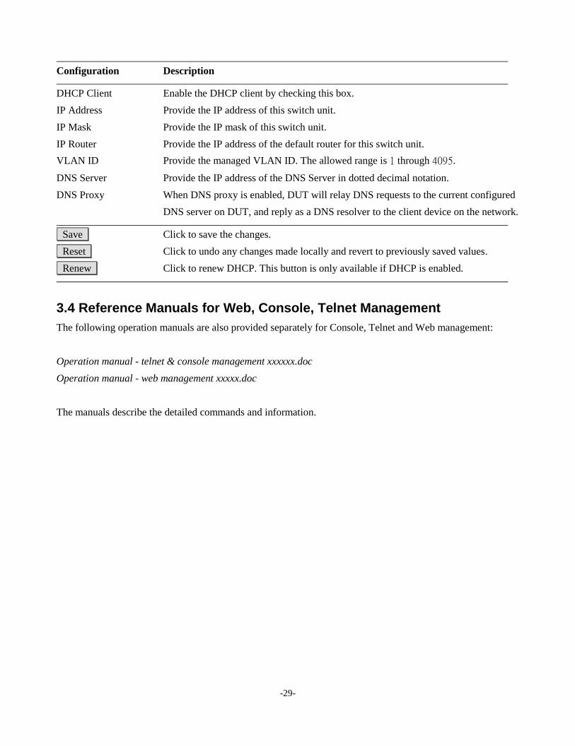
Configuration Description
DHCP Client Enable the DHCP client by checking this box.
IP Address Provide the IP address of this switch unit.
IP Mask Provide the IP mask of this switch unit.
IP Router Provide the IP address of the default router for this switch unit.
VLAN ID Provide the managed VLAN ID. The allowed range is 1 through 4095.
DNS Server Provide the IP address of the DNS Server in dotted decimal notation.
DNS Proxy When DNS proxy is enabled, DUT will relay DNS requests to the current configured
DNS server on DUT, and reply as a DNS resolver to the client device on the network.
Save Click to save the changes.
Reset Click to undo any changes made locally and revert to previously saved values.
Renew Click to renew DHCP. This button is only available if DHCP is enabled.
3.4 Reference Manuals for Web, Console, Telnet Management
The following operation manuals are also provided separately for Console, Telnet and Web management:
Operation manual - telnet & console management xxxxxx.doc
Operation manual - web management xxxxx.doc
The manuals describe the detailed commands and information.
-30-
3.5 Configuration for SNMP Management
The switch supports SNMP v1, SNMP v2c, and SNMP v3 management. Make sure the related settings are
well-configured for the switch before you start the SNMP management from an SNMP manager.
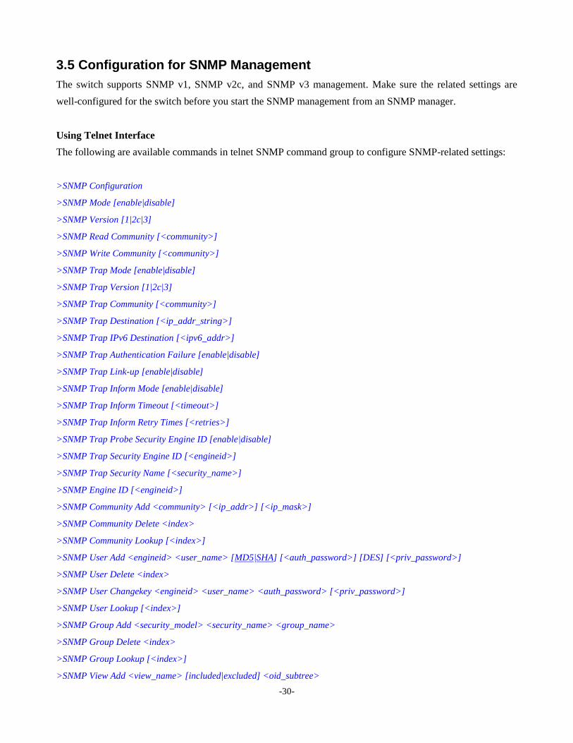
Using Telnet Interface
The following are available commands in telnet SNMP command group to configure SNMP-related settings:
>SNMP Configuration
>SNMP Mode [enable|disable]
>SNMP Version [1|2c|3]
>SNMP Read Community [<community>]
>SNMP Write Community [<community>]
>SNMP Trap Mode [enable|disable]
>SNMP Trap Version [1|2c|3]
>SNMP Trap Community [<community>]
>SNMP Trap Destination [<ip_addr_string>]
>SNMP Trap IPv6 Destination [<ipv6_addr>]
>SNMP Trap Authentication Failure [enable|disable]
>SNMP Trap Link-up [enable|disable]
>SNMP Trap Inform Mode [enable|disable]
>SNMP Trap Inform Timeout [<timeout>]
>SNMP Trap Inform Retry Times [<retries>]
>SNMP Trap Probe Security Engine ID [enable|disable]
>SNMP Trap Security Engine ID [<engineid>]
>SNMP Trap Security Name [<security_name>]
>SNMP Engine ID [<engineid>]
>SNMP Community Add <community> [<ip_addr>] [<ip_mask>]
>SNMP Community Delete <index>
>SNMP Community Lookup [<index>]
>SNMP User Add <engineid> <user_name> [MD5|SHA] [<auth_password>] [DES] [<priv_password>]
>SNMP User Delete <index>
>SNMP User Changekey <engineid> <user_name> <auth_password> [<priv_password>]
>SNMP User Lookup [<index>]
>SNMP Group Add <security_model> <security_name> <group_name>
>SNMP Group Delete <index>
>SNMP Group Lookup [<index>]
>SNMP View Add <view_name> [included|excluded] <oid_subtree>
-31-
>SNMP View Delete <index>
>SNMP View Lookup [<index>]
>SNMP Access Add <group_name> <security_model> <security_level> [<read_view_name>] [<write_view_name>]
>SNMP Access Delete <index>
>SNMP Access Lookup [<index>]
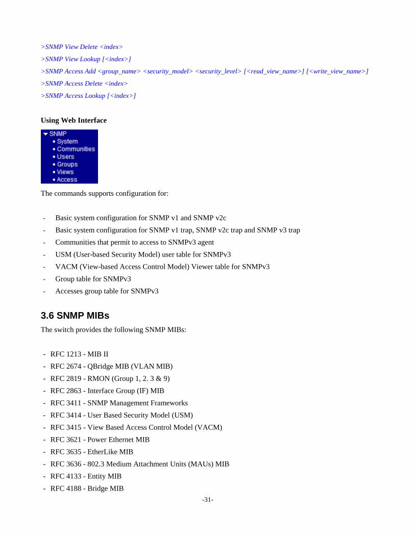
Using Web Interface
The commands supports configuration for:
- Basic system configuration for SNMP v1 and SNMP v2c
- Basic system configuration for SNMP v1 trap, SNMP v2c trap and SNMP v3 trap
- Communities that permit to access to SNMPv3 agent
- USM (User-based Security Model) user table for SNMPv3
- VACM (View-based Access Control Model) Viewer table for SNMPv3
- Group table for SNMPv3
- Accesses group table for SNMPv3
3.6 SNMP MIBs
The switch provides the following SNMP MIBs:
- RFC 1213 - MIB II
- RFC 2674 - QBridge MIB (VLAN MIB)
- RFC 2819 - RMON (Group 1, 2. 3 & 9)
- RFC 2863 - Interface Group (IF) MIB
- RFC 3411 - SNMP Management Frameworks
- RFC 3414 - User Based Security Model (USM)
- RFC 3415 - View Based Access Control Model (VACM)
- RFC 3621 - Power Ethernet MIB
- RFC 3635 - EtherLike MIB
- RFC 3636 - 802.3 Medium Attachment Units (MAUs) MIB
- RFC 4133 - Entity MIB
- RFC 4188 - Bridge MIB
-32-
- RFC 4668 - RADIUS Authentication Client MIB
- RFC 5519 - Multicast Group Membership Discovery (MGMD) MIB
- IEEE 802.1 MSTP MIB
- IEEE 802.1AB LLDP MIB
- IEEE 802.1X Port Access Entity (PAE) MIB
- TIA 1057 LLDP Media Endpoint Discovery (MED) MIB
- IEEE 802.1-Q-BRIDGE MIB
- Private SFPDDM MIB (DDM status)
- Private reboot MIB (Remote boot over SNMP)
- Private TFTP firmware update MIB (TFTP Firmware update via SNMP)
One product MIB file is also available in the product CD for SNMP manager software.
-33-
4. Redundant Ring Applications
4.1 Auto Multi-Ring Technology
Auto Multi-Ring Technology was developed especially for switches connected in ring topology which
needs redundant support when any failure occurs in ring. For large network, more than one ring
connections are very common. Auto Multi-Ring Technology implementation can support more than
one ring connection within a switch. It is also able to work with RSTP support concurrently in the
switch.
Some basic information is:
Supports up to five rings in one switch
Supports up to 30 member switches in one ring
Provides fast response time than RSTP protocol
Works with RSTP protocol concurrently within one switch
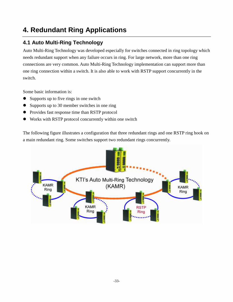
The following figure illustrates a configuration that three redundant rings and one RSTP ring hook on
a main redundant ring. Some switches support two redundant rings concurrently.
-34-
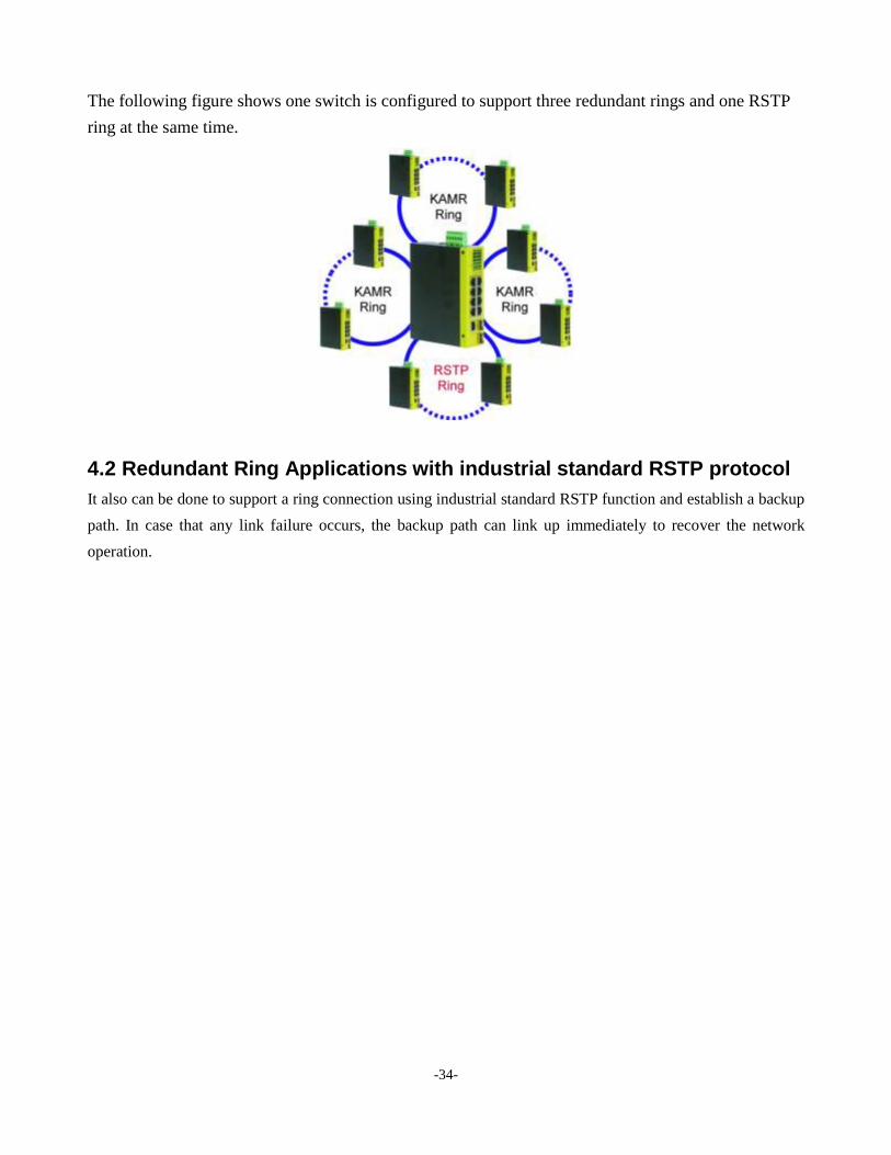
The following figure shows one switch is configured to support three redundant rings and one RSTP
ring at the same time.
4.2 Redundant Ring Applications with industrial standard RSTP protocol
It also can be done to support a ring connection using industrial standard RSTP function and establish a backup
path. In case that any link failure occurs, the backup path can link up immediately to recover the network
operation.