Embed Size (px)
Citation preview
7.5 to 12.5 TonsNet Cooling Capacity − 86,000 to 140,000 Btuh
Gas Input Heat Capacity − 130,000 to 240,000 Btuh
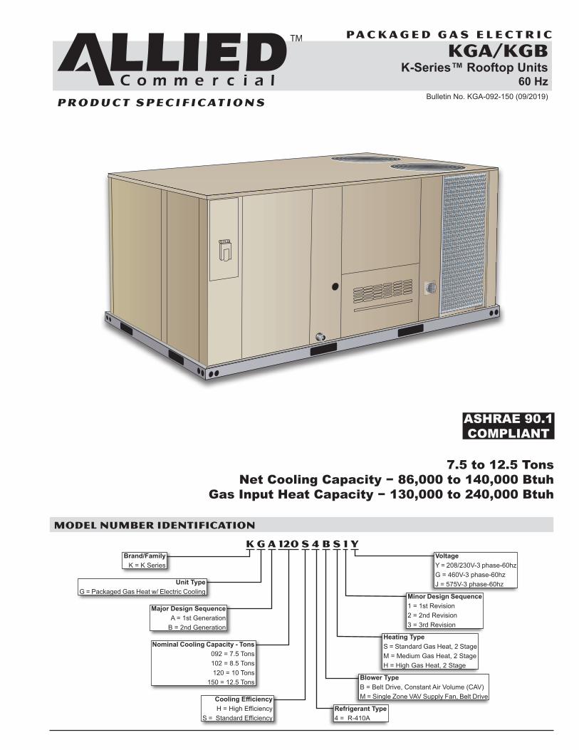
MODEL NUMBER IDENTIFICATION
ASHRAE 90.1COMPLIANT
K G A 120 S 4 B S 1 YBrand/Family
K = K Series
Unit Type G = Packaged Gas Heat w/ Electric Cooling
Major Design Sequence A = 1st Generation
B = 2nd Generation
Nominal Cooling Capacity - Tons 092 = 7.5 Tons 102 = 8.5 Tons 120 = 10 Tons
150 = 12.5 Tons
Cooling Efficiency H = High Efficiency
S = Standard EfficiencyRefrigerant Type 4 = R-410A
Heating Type S = Standard Gas Heat, 2 Stage M = Medium Gas Heat, 2 Stage H = High Gas Heat, 2 Stage
Minor Design Sequence 1 = 1st Revision 2 = 2nd Revision 3 = 3rd Revision
Voltage Y = 208/230V-3 phase-60hz G = 460V-3 phase-60hz J = 575V-3 phase-60hz
Blower Type B = Belt Drive, Constant Air Volume (CAV) M = Single Zone VAV Supply Fan, Belt Drive
P A C K A G E D G A S E L E C T R I C
Bulletin No. KGA-092-150 (09/2019)
KGA/KGBK-Series™ Rooftop Units
60 Hz
KGA/KGB 7.5-12.5 TON ROOFTOP UNITS
P R O D U C T S P E C I F I C AT I O N S
K-Series Packaged Gas / Electric 7.5 to 12.5 Ton / Page 2
FEATURES AND BENEFITS
B
I J
C
D
E
F
G
HK
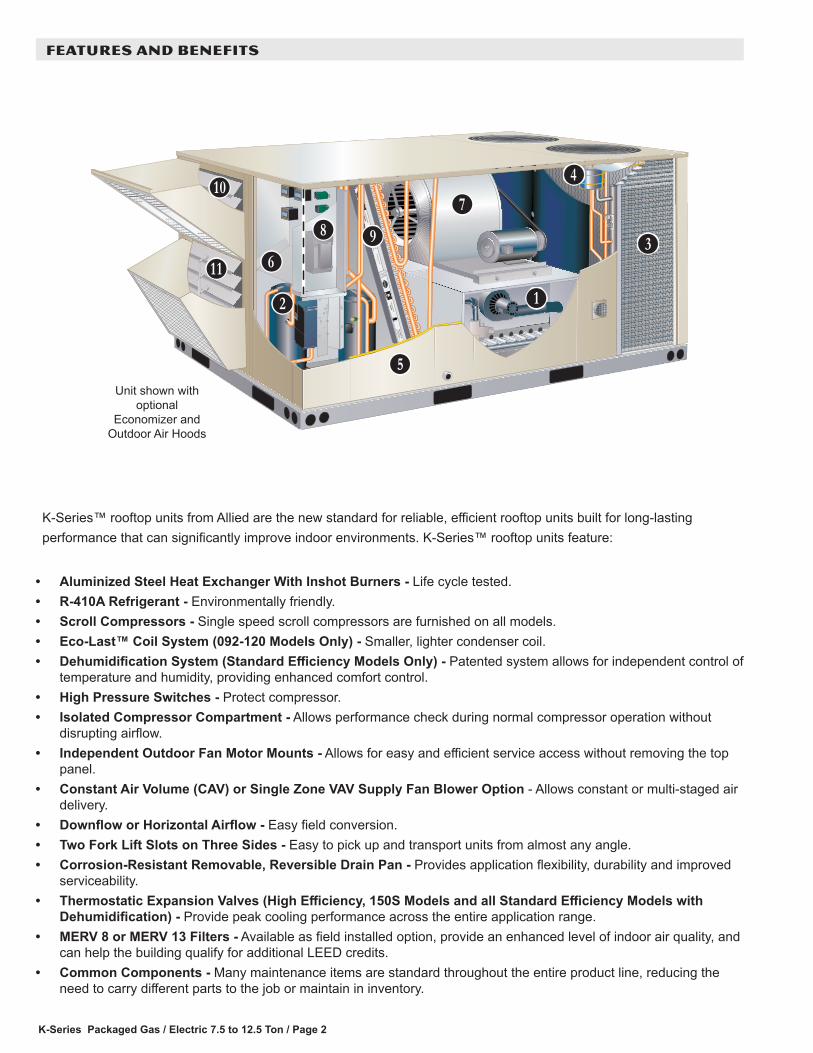
Unit shown with optional
Economizer and Outdoor Air Hoods
K-Series™ rooftop units from Allied are the new standard for reliable, efficient rooftop units built for long-lasting performance that can significantly improve indoor environments. K-Series™ rooftop units feature:
• Aluminized Steel Heat Exchanger With Inshot Burners - Life cycle tested.• R-410A Refrigerant - Environmentally friendly.• Scroll Compressors - Single speed scroll compressors are furnished on all models.• Eco-Last™ Coil System (092-120 Models Only) - Smaller, lighter condenser coil.• Dehumidification System (Standard Efficiency Models Only) - Patented system allows for independent control of
temperature and humidity, providing enhanced comfort control.• High Pressure Switches - Protect compressor.• Isolated Compressor Compartment - Allows performance check during normal compressor operation without
disrupting airflow.• Independent Outdoor Fan Motor Mounts - Allows for easy and efficient service access without removing the top
panel.• Constant Air Volume (CAV) or Single Zone VAV Supply Fan Blower Option - Allows constant or multi-staged air
delivery.• Downflow or Horizontal Airflow - Easy field conversion.• Two Fork Lift Slots on Three Sides - Easy to pick up and transport units from almost any angle.• Corrosion-Resistant Removable, Reversible Drain Pan - Provides application flexibility, durability and improved
serviceability.• Thermostatic Expansion Valves (High Efficiency, 150S Models and all Standard Efficiency Models with
Dehumidification) - Provide peak cooling performance across the entire application range.• MERV 8 or MERV 13 Filters - Available as field installed option, provide an enhanced level of indoor air quality, and
can help the building qualify for additional LEED credits.• Common Components - Many maintenance items are standard throughout the entire product line, reducing the
need to carry different parts to the job or maintain in inventory.
L
K-Series Packaged Gas / Electric 7.5 to 12.5 Ton / Page 3
FEATURES AND BENEFITS
APPROVALSAHRI Certified to AHRI Standard 340/360.Units are ETL listed.Units are certified by CSA.Components bonded for grounding to meet safety standards for servicing required by UL, ULC and National and Canadian Electrical Codes.All models are ASHRAE 90.1-2010 energy efficiency compliant and meet or exceed requirements of Section 6.8.Models equipped with the Single Zone VAV Supply Fan option meet California Code of Regulations, Title 24 and ASHRAE 90.1-2010 Section 6.4.3.10 requirements for staged airflow.ISO 9001 Registered Manufacturing Quality System.
WARRANTYLimited ten years aluminized heat exchanger, limited fifteen years optional stainless steel heat exchanger.Limited five years on compressors.Limited three years on the Eco-Last™ Coil System.Limited five years Optional High Performance Economizers.Limited one year all other covered components.
A
HEATING SYSTEMAluminized steel inshot burners, direct spark ignition, electronic flame sensor, combustion air inducer, redundant automatic dual stage gas valve with manual shut-off.
Heat ExchangerTubular construction, aluminized steel, life cycle tested.Optional Stainless Steel Heat Exchanger is required if mixed air temperature is below 45°F.
Electronic Pilot IgnitionElectronic spark igniter provides positive direct ignition of burners on each operating cycle. The system permits main gas valve to stay open only when the burners are proven to be lit. Should a loss of flame occur, the gas valve closes, shutting off the gas to the burners. Ignition module has LED to indicate status and aid in troubleshooting.Watchguard circuit on module automatically resets ignition controls after one hour of continuous thermostat demand after unit lockout, eliminating nuisance service calls.Ignition control is factory installed in the controls section.
B
Limit ControlFactory installed, limit control with fixed temperature setting. Heat limit control protects heat exchanger and other components from overheating.
Safety SwitchesFlame roll-out switch, flame sensor and combustion air inducer proving switch protect system operation.
Required Selections
Gas Input Choice - Order one:Standard Gas Heat, 2 Stage (84,500/130,000 Btuh)Medium Gas Heat, 2 Stage (117,000/180,000 Btuh)High Gas Heat, 2 Stage (156,000/240,000 Btuh)
Options/Accessories
Factory InstalledStainless Steel Heat ExchangerRequired if mixed air temperature is below 45°F.
Field InstalledBottom Gas Piping KitAllows bottom gas entry.
Combustion Air Intake ExtensionsRecommended for use with existing flue extension kits in areas where high snow areas can block intake air.
Low Temperature Vestibule HeaterElectric heater automatically controls minimum temperature in gas burner compartment when temperature is below -40°F. CSA certified to allow operation of unit down to -60°F.
LPG/Propane KitsConversion kit to field change over units from Natural Gas to LPG/Propane.
CONTENTSBlower Data . . . . . . . . . . . . . . . . . . . . . . . . . . . . . . . . .29Dimensions - Accessories . . . . . . . . . . . . . . . . . . . . . . . . .43Dimensions - Unit . . . . . . . . . . . . . . . . . . . . . . . . . . . . .42Electrical Data. . . . . . . . . . . . . . . . . . . . . . . . . . . . . . . .35Features And Benefits . . . . . . . . . . . . . . . . . . . . . . . . . . . 2Dehumidification System Ratings . . . . . . . . . . . . . . . . . . . . . .27Model Number Identification . . . . . . . . . . . . . . . . . . . . . . . . 1Optional Conventional Temperature Control Systems . . . . . . . . . . .40Options / Accessories . . . . . . . . . . . . . . . . . . . . . . . . . . . .11Outdoor Sound Data . . . . . . . . . . . . . . . . . . . . . . . . . . . .39Ratings . . . . . . . . . . . . . . . . . . . . . . . . . . . . . . . . . . .19Specifications . . . . . . . . . . . . . . . . . . . . . . . . . . . . . . . .14Specifications - Gas Heat . . . . . . . . . . . . . . . . . . . . . . . . . .18Unit Clearances . . . . . . . . . . . . . . . . . . . . . . . . . . . . . .39Weight Data . . . . . . . . . . . . . . . . . . . . . . . . . . . . . . . . .41
K-Series Packaged Gas / Electric 7.5 to 12.5 Ton / Page 4
Filter/DriersHigh capacity filter/drier protects the system from dirt and moisture.
High Pressure SwitchesProtects the compressor from overload conditions such as dirty condenser coils, blocked refrigerant flow, or loss of outdoor fan operation. Auto reset.
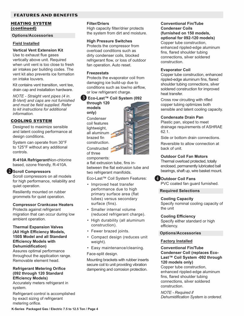
FreezestatsProtects the evaporator coil from damaging ice build-up due to conditions such as low/no airflow, or low refrigerant charge. Eco-Last™ Coil System (092 through 120 models only) Condenser coil features lightweight, all aluminum brazed fin construction.Constructed of three components: a flat extrusion tube, fins in-between the flat extrusion tube and two refrigerant manifolds.Eco-Last™ Coil System Features:• Improved heat transfer
performance due to high primary surface area (flat tubes) versus secondary surface (fins).
• Smaller internal volume (reduced refrigerant charge).
• High durability (all aluminum construction).
• Fewer brazed joints.• Compact design (reduces unit
weight).• Easy maintenance/cleaning.Face-split design.Mounting brackets with rubber inserts secure coil to unit providing vibration dampening and corrosion protection.
D
HEATING SYSTEM (continued)
Options/Accessories
Field InstalledVertical Vent Extension KitUse to exhaust flue gases vertically above unit. Required when unit vent is too close to fresh air intakes per building codes. The vent kit also prevents ice formation on intake louvers.Kit contains vent transition, vent tee, drain cap and installation hardware.NOTE - Straight vent pipes (4 in. B-Vent) and caps are not furnished and must be field supplied. Refer to kit instructions for additional information.
COOLING SYSTEMDesigned to maximize sensible and latent cooling performance at design conditions.System can operate from 30°F to 125°F without any additional controls.
R-410A RefrigerantNon-chlorine based, ozone friendly, R-410A.Scroll CompressorsScroll compressors on all models for high performance, reliability and quiet operation.Resiliently mounted on rubber grommets for quiet operation.
Compressor Crankcase HeatersProtects against refrigerant migration that can occur during low ambient operation.
Thermal Expansion Valves (All High Efficiency Models, 150S Model and all Standard Efficiency Models with Dehumidification) Assures optimal performance throughout the application range.Removable element head.
Refrigerant Metering Orifice (092 through 120 Standard Efficiency Models)Accurately meters refrigerant in system.Refrigerant control is accomplished by exact sizing of refrigerant metering orifice.
C
Conventional Fin/Tube Condenser Coils (furnished on 150 models, optional for 092-120 models)Copper tube construction, enhanced rippled-edge aluminum fins, flared shoulder tubing connections, silver soldered construction.
Evaporator CoilCopper tube construction, enhanced rippled-edge aluminum fins, flared shoulder tubing connections, silver soldered construction for improved heat transfer.Cross row circuiting with rifled copper tubing optimizes both sensible and latent cooling capacity.
Condensate Drain PanPlastic pan, sloped to meet drainage requirements of ASHRAE 62.1.Side or bottom drain connections.Reversible to allow connection at back of unit.
Outdoor Coil Fan MotorsThermal overload protected, totally enclosed, permanently lubricated ball bearings, shaft up, wire basket mount.
Outdoor Coil FansPVC coated fan guard furnished.
Required Selections
Cooling CapacitySpecify nominal cooling capacity of the unit
Cooling EfficiencySpecify either standard or high efficiency.
Options/Accessories
Factory InstalledConventional Fin/Tube Condenser Coil (replaces Eco-Last™ Coil System -092 through 120 models only)Copper tube construction, enhanced rippled-edge aluminum fins, flared shoulder tubing connections, silver soldered construction.NOTE - Required if Dehumidification System is ordered.
E
FEATURES AND BENEFITS
K-Series Packaged Gas / Electric 7.5 to 12.5 Ton / Page 5
COOLING SYSTEM (continued)
Options/Accessories
Field InstalledCondensate Drain TrapAvailable in copper or PVC.
Drain Pan Overflow SwitchMonitors condensate level in drain pan, shuts down unit if drain becomes clogged.
Low Ambient ControlsUnits operate satisfactorily down to 45°F outdoor air temperature without any additional controls.Two low ambient control options are available for field installation:
1. Low Ambient Control Kit (30°F) - Allows unit operation down to 30°F.
2. Low Ambient Control Kit (0°F) - Allows unit operation down to 0°F without evaporator coil icing. Head pressure speed control reduces outdoor fan operation during low ambient conditions until head pressure rises to the setpoint. Pressure transducers are mounted on the liquid lines. High pressure switches are furnished to replace existing. Wiring harnesses are furnished for simple plug-in wiring to fans and controller.
CONTROLSUnit ControlAll control voltage is provided via a 24V (secondary) transformer with built-in circuit breaker protection.
Heat/Cool Staging - Capable of up to 2 heat / 2 cool staging with a third party DDC control system or thermostat.Low Voltage Terminal Block - Provides screw terminal connections for thermostat or controller wiring.Night Setback Mode - Saves energy by closing outdoor air dampers and operating supply fan on thermostat demand only.
F
Options/Accessories
Field InstalledSmoke DetectorPhotoelectric type, installed in supply air section, return air section or both sections. Available with power board and single sensor (supply or return) or power board and two sensors (supply and return).
CABINETConstructionHeavy-gauge steel panels and full perimeter heavy-gauge galvanized steel base rail provides structural integrity for transportation, handling, and installation.Base rails have rigging holes.Three sides of the base rail have forklift slots.Raised edges around duct and power entry openings in the bottom of the unit provide additional protection against water entering the building.
Airflow ChoiceUnits are shipped in downflow (vertical) configuration, can be field converted to horizontal airflow with optional Horizontal Discharge Kit.
Duct FlangesProvided for horizontal duct attachment.
Power/Gas EntryElectrical and gas lines can be brought through the unit base or through horizontal access knock-outs.
Exterior PanelsConstructed of heavy-gauge, galvanized steel with a two-layer enamel paint finish.
InsulationAll panels adjacent to conditioned air are fully insulated with non-hygroscopic fiberglass insulation.Unit base is fully insulated. The insulation also serves as an air seal to the roof curb, eliminating the need to add a seal during installation.
G
Access PanelsAccess panels are provided for the filter section, heating/blower section, and the compressor/controls section.Options/Accessories
Factory InstalledCorrosion ProtectionA completely flexible immersed coating with an electrodeposited dry film process. (AST ElectroFin E-Coat) Meets Mil Spec MIL-P-53084, ASTM B117 Standard Method Salt Spray Testing.Indoor Corrosion Protection: - Coated coil- Coated reheat coil (Dehumidification- Painted blower housing- Painted baseOutdoor Corrosion Protection: - Coated coil- Painted base
Hinged Access PanelsLarge access panels are hinged and have quarter-turn latches for quick and easy access to maintenance areas (filter, compressor / controls, heating / blower).
FEATURES AND BENEFITS
K-Series Packaged Gas / Electric 7.5 to 12.5 Ton / Page 6
FEATURES AND BENEFITS
CABINET (continued)
Options/Accessories
Field InstalledCombination Coil/Hail GuardsHeavy gauge steel frame painted to match cabinet with expanded metal mesh to protect the outdoor coil from damage.
Horizontal Discharge KitConsists of duct covers to block off downflow supply and return air openings for horizontal applications.Also includes return air duct flanges for end return air when economizer is used in horizontal applications.NOTE - When configuring unit for horizontal application with economizer, a separate Horizontal Barometric Relief Damper with Hood must be ordered separately for installation in the return air duct.
BLOWERA wide selection of supply air blower options are available to meet a variety of airflow requirements.
MotorOverload protected, equipped with ball bearings. Belt drive motors are offered on all models and are available in several different sizes to maximize air performance.
Supply Air BlowerForward curved blades, double inlet, blower wheel is statically and dynamically balanced. Equipped with ball bearings and adjustable pulley (allows speed change),.Blower assembly slides out of unit for servicing.
H
Required Selections
Select Constant Air Volume (CAV) or Single Zone VAV Supply Fan Supply Air Blower OptionOrder blower motor horsepower and drive kit number required when base unit is ordered, see Drive Kit Specifications Table.
CAV OperationOn units ordered with the Constant Air volume (CAV) option, the supply air blower will provide a constant volume of air.
Single Zone VAV Supply Fan OperationUnits ordered with the Single Zone VAV Supply Fan option utilize a Variable Frequency Drive (VFD) to stage the supply air blower airflow. The VFD alters the frequency and voltage of the power supply to the blower to control blower speed.The supply air blower has two speeds:3. Low speed for part-load
cooling operation. Note - Low speed is 66% of high speed.
4. High speed for full load cooling and all heat modes.
Full speed blower operation is set by adjusting the motor pulley to deliver the desired air volume.The ventilation speed is selectable between high and low speed.NOTE - Part load airflow in cooling mode on Single Zone VAV Supply Fan units should not be set below 220 cfm/nominal full load ton to reduce the risk of evaporator coil freeze-up.The VFD has an operational range of -40 to 125° F outdoor air ambient temperature. Lower operating costs are obtained when the blower is operated on lower speeds.
Single Zone VAV Supply Fan Sequence of OperationVentilation speed is determined by the VENT SPEED switch setting on VFD control board (LO or HI).Blower operates in low speed for mechanical cooling (Y1).Blower operates in high speed for any other mode (free cooling, mechanical cooling Y1+Y2, and heating).Economizer damper minimum position is fully closed in unoccupied mode.In occupied mode, the economizer damper minimum position is determined by the setting of the two potentiometers on VFD control board.• LO SPD MIN POS
potentiometer sets the minimum position when blower is operating at low speed.
• HI SPD MIN POS potentiometer sets the minimum position when blower is operating at high speed.
Options/Accessories
Field InstalledVFD Manual Bypass KitVFD Manual Bypass Control is available as a kit for units equipped with the Single Zone VAV Supply Fan option.The VFD Manual Bypass Control is a manual bypass and is enabled by re-configuring the wiring on the unit.
K-Series Packaged Gas / Electric 7.5 to 12.5 Ton / Page 7
FEATURES AND BENEFITS
ELECTRICALMarked & Color-Coded WiringAll electrical wiring is color-coded and marked to identify which components it is connecting.
Electrical PlugsPositive connection electrical plugs are used to connect common accessories or maintenance parts for easy removal or installation.Phase Monitor (Factory Installed on Units Equipped with the Single Zone VAV Supply Fan)Phase monitor located in the control compartment detects the phasing of incoming power. If the incoming power is out of phase or if any of the three phases are lost, an indicator LED on the phase monitor will turn red and the unit will not start. In normal operation with correct incoming power phasing, the LED will be green.
Required Selections
Voltage ChoiceSpecify when ordering base unit.
Options/Accessories
Factory or Field InstalledDisconnect SwitchAccessible from outside of unit, spring loaded weatherproof cover furnished. Main power to the unit is field connected to the disconnect which allows all power to be shut off for service. See Options/Accessories tables for ordering information, page 11.
GFI Service Outlets (2)115V ground fault circuit interrupter (GFCI) type, non-powered, field-wired.
Field InstalledGFI Weatherproof CoverSingle-gang cover.Heavy-duty UV-resistant polycarbonate case construction.Hinged base cover with gasket.
I
INDOOR AIR QUALITYAir FiltersDisposable 2 inch filters furnished as standard.
Options/Accessories
Field InstalledHigh Efficiency Air FiltersDisposable MERV 8 or MERV 13 (Minimum Efficiency Reporting Value based on ASHRAE 52.2) efficiency 2 inch pleated filters.
Replacement Filter Media Kit With FrameReplaces existing pleated filter media. Includes washable metal mesh screen and metal frame with clip for holding replaceable non-pleated filter.
JUVC Germicidal Lamps
Germicidal lamps emit ultra-violet (UV-C) energy, which has been proven to be effective in reducing microbes such as viruses, bacteria, yeasts, and molds. This process either destroys the organism or controls its ability to reproduce.UV-C energy greatly reduces the growth and proliferation of mold and other bioaerosols (bacteria and viruses) on illuminated surfaces (particularly coil and drain pan).Lamps are field installed in the blower/evaporator coil section.All necessary hardware for installation is included.Lamps operate on 208/230V power supply. Step-down transformer must be field supplied when used with 460V and 575V rooftop units.Magnetic safety interlock terminates power when access panels are removed.Approved by ETL.
Indoor Air Quality (CO2) SensorsMonitors CO2 levels, reports to the Unit Controller which adjusts economizer dampers as needed.
K-Series Packaged Gas / Electric 7.5 to 12.5 Ton / Page 8
ECONOMIZER OPTIONS
Factory or Field InstalledEconomizer (Standard and High Performance Common Features)Downflow or Horizontal with Outdoor Air Hood and Barometric Relief Dampers with Exhaust Hood.Barometric Relief Dampers allow relief of excess air, aluminum blade dampers prevent blow back and outdoor air infiltration during off cycle, bird screen furnished.NOTE - Optional Horizontal Low Profile Barometric Relief Dampers with Exhaust Hood are available for field installation in a reduced space.Occupied/Unoccupied mode with field furnished setback thermostat.Demand Control Ventilation (DCV) ready using optional CO2 sensors.Mixed Air Sensor is furnished for field installation in the rooftop unit. Sensor is factory installed when Economizers are factory installed.Single sensible sensor is furnished with Economizer and enables economizer operation if the outdoor temperature is less than the setpoint of the control.
Standard Economizer Features (Not for Title 24)Gear-driven action, return air and outdoor air dampers, plug-in connections to unit, nylon bearings, neoprene seals, 24-volt, fully-modulating spring return motor.
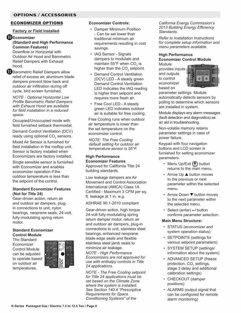
Standard Economizer Control ModuleThe Standard Economizer Control Module can be adjusted to operate based on outdoor air temperatures.
K
L
Economizer Controls:• Damper Minimum Position
- Can be set lower than traditional minimum air requirements resulting in cost savings.
• IAQ Sensor - Signals dampers to modulate and maintain 55°F when CO2 is higher than the CO2 setpoint.
• Demand Control Ventilation (DCV) LED - A steady green Demand Control Ventilation LED indicates the IAQ reading is higher than setpoint and requires more fresh air.
• Free Cool LED - A steady green LED indicates outdoor air is suitable for free cooling.
Free Cooling runs when outdoor air temperature is lower than the set temperature on the economizer control. NOTE: The Free Cooling default setting for outdoor air temperature sensor is 55°F.
High Performance Economizer Features Approved for California Title 24 building standards.Low leakage dampers are Air Movement and Control Association International (AMCA) Class 1A Certified - Maximum 3 CFM per sq. ft. leakage at 1 in. w.g.ASHRAE 90.1-2010 compliantGear-driven action, high torque 24-volt fully-modulating spring return damper motor, return air and outdoor air dampers, plug-in connections to unit, stainless steel bearings, enhanced neoprene blade edge seals and flexible stainless steel jamb seals to minimize air leakage.NOTE - High Performance Economizers are not approved for use with enthalpy controls in Title 24 applications.NOTE - The Free Cooling setpoint for Title 24 applications must be set based on the Climate Zone where the system is installed. See Section 140.4 “Prescriptive Requirements for Space Conditioning Systems” of the
California Energy Commission’s 2013 Building Energy Efficiency Standards.Refer to Installation Instructions for complete setup information and menu parameters available.
High Performance Economizer Control ModuleModule provides inputs and outputs to control economizer based on parameter settings. Module automatically detects sensors by polling to determine which sensors are installed in system.Module displays any alarm messages (fault detection and diagnostics) as an aid in troubleshooting.Non-volatile memory retains parameter settings in case of power failure.Keypad with four navigation buttons and LCD screen is furnished for setting economizer parameters.
• Menu Up/Exit button returns to the main menu.
• Arrow Up button moves to the previous or next parameter within the selected menu.
• Arrow Down button moves to the next parameter within the selected menu.
• Select (enter) button confirms parameter selection.
Main Menu Structure:• STATUS (economizer and
system operation status)• SETPOINTS (settings for
various setpoint parameters)• SYSTEM SETUP (settings/
information about the system)• ADVANCED SETUP (freeze
protection, CO2 settings, stage 3 delay and additional calibration settings)
• CHECKOUT (damper positions)
• ALARMS (output signal that can be configured for remote alarm monitoring)
OPTIONS / ACCESSORIES

K-Series Packaged Gas / Electric 7.5 to 12.5 Ton / Page 9
OPTIONS / ACCESSORIES
ROOF CURBSNailer strip furnished, mates to unit, US National Roofing Contractors Approved, shipped knocked down.Hybrid Roof Curbs, DownflowRoof curb can be assembled using interlocking tabs to fasten corners together. No tools required.Curb can also be fastened together with furnished hardware.Available in 8, 14, 18, and 24 inch heights.
Adjustable Pitch CurbFully adjustable pitch curbs (3/4 in. per foot in any direction) provide a level platform for rooftop units allowing flexible installations on roofs with uneven or sloped angles.Uses interlocking tabs to fasten corners together. No tools required.Hardware is furnished to connect upper curb with lower curb.Available in 14 inch height
Adaptor Curbs (not shown)Curbs are regionally sourced. Dimensions will vary based upon the source. Contact your local sales representative for a detailed cut sheet with applicable dimensions.
CEILING DIFFUSERSCeiling Diffusers (Flush or Step-Down)Diffuser face and grilles with white powder coat finish, insulated (UL listed duct liner), diffuser box with collars for duct connection, fixed blades (flush diffusers) and double deflection blades (step-down diffusers), provisions for suspending, internally sealed (prevents recirculation), removable return air grille, adapts to T-bar ceiling grids or plaster ceilings.
Transitions (Supply and Return)Used with diffusers, installs in roof curb, galvanized steel construction, flanges furnished for duct connection to diffusers, fully insulated.
ECONOMIZER OPTIONS (continued)
Factory or Field InstalledSingle Enthalpy Temperature Control (Not for Title 24)Outdoor air enthalpy sensor enables Economizer if the outdoor enthalpy is less than the setpoint of the control.
Field InstalledDifferential Enthalpy Control (Not for Title 24)Order two Single Enthalpy Controls. One is field installed in the return air section, the other in the outdoor air section. Allows the economizer control board to select between outdoor air or return air, whichever has lower enthalpy.
EXHAUST OPTIONS
Field InstalledHorizontal Low Profile Barometric Relief DampersReplaces barometric relief dampers furnished with Economizer.For use when unit is configured for horizontal applications in a reduced space requiring an economizer.Allows relief of excess air.Aluminum blade dampers prevent blow back and outdoor air infiltration during off cycle.Field installed in return air duct.Exhaust hood with bird screen furnished.Requires Horizontal Discharge Kit.Power Exhaust FanInstalls internal to unit for downflow applications only with economizer option. Provides exhaust air pressure relief. Interlocked to run when supply air blower is operating, fan runs when outdoor air dampers are 50% open (adjustable), motor is overload protected. Requires Economizer with Outdoor Air Hood and Barometric Relief Dampers. Fan is 20 in. diameter with 5 blades (K1PWRE10B) with 1/3 hp motor.
OUTDOOR AIR OPTIONS
Factory or Field InstalledOutdoor Air Damper - Downflow or Horizontal With Air HoodLinked mechanical dampers, 0 to 25% (fixed) outdoor air adjustable, installs in unit. Includes outdoor air hood.Automatic model features fully modulating spring return damper motor with plug-in connection.Manual model features a slide damper.Maximum mixed air temperature in cooling mode: 100°F.
K-Series Packaged Gas / Electric 7.5 to 12.5 Ton / Page 10
OPTIONS / ACCESSORIES
DEHUMIDIFICATION SYSTEM
NOTE - Not available with Eco-Last™ Coil System. Conventional Fin/Tube condenser coil must be ordered as a factory option. Factory installed option designed to control humidity.Provides dehumidification on demand using ASHRAE 90.1 recommended method for comfort conditioning humidity control.Unit comes equipped with one row reheat coil, solenoid valve and humidity controller.A thermostat with a dehumidification output, a dehumidistat, or a DDC controller with an isolated output is required to control humidity and must be located in the occupied space.
BenefitsImproves indoor air quality.Helps prevent damage due to high humidity levels.Improves comfort levels by reducing space humidity levels.
OPERATIONNo Dehumidification DemandThe unit will operate conventionally whenever there is a demand for cooling or heating and no dehumidification demand.Free cooling is only permitted when there is no demand for dehumidification.
Dehumidification Demand OnlyDehumidification is initiated by an output from a dehumidistat (furnished), an optional thermostat with a dehumidification output or an optional DDC controller with an isolated output to control humidity.Reheat operation will initiate on a dehumidification demand and does not require a cooling demand.The unit will operate in the dehumidification mode until the relative humidity of the conditioned space is below the setpoint.This operation reduces sensible cooling capacity and extends compressor run time to control humidity when the cooling load is low.
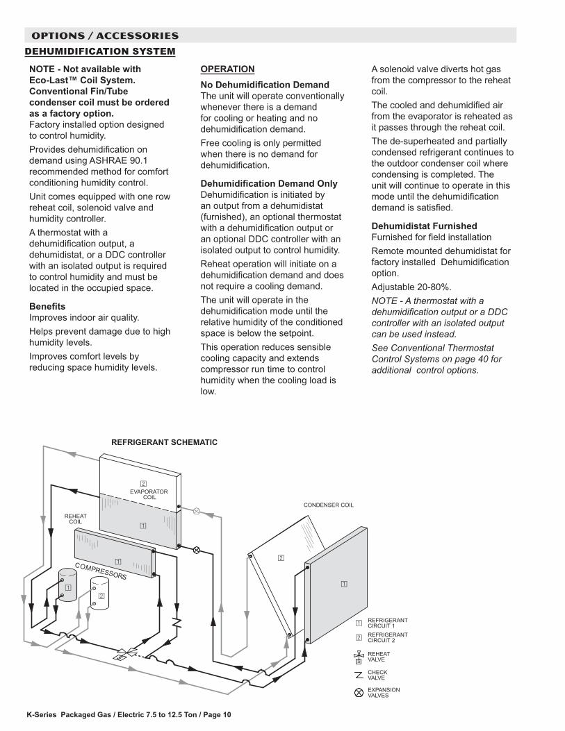
A solenoid valve diverts hot gas from the compressor to the reheat coil.The cooled and dehumidified air from the evaporator is reheated as it passes through the reheat coil.The de-superheated and partially condensed refrigerant continues to the outdoor condenser coil where condensing is completed. The unit will continue to operate in this mode until the dehumidification demand is satisfied.
Dehumidistat FurnishedFurnished for field installationRemote mounted dehumidistat for factory installed Dehumidification option.Adjustable 20-80%.NOTE - A thermostat with a dehumidification output or a DDC controller with an isolated output can be used instead.See Conventional Thermostat Control Systems on page 40 for additional control options.
EXPANSIONVALVES
REHEATVALVE
CHECKVALVE
REHEATCOIL
EVAPORATOR COIL
CONDENSER COIL
REFRIGERANTCIRCUIT 1REFRIGERANTCIRCUIT 2
REFRIGERANT SCHEMATIC
K-Series Packaged Gas / Electric 7.5 to 12.5 Ton / Page 11
OPTIONS / ACCESSORIES
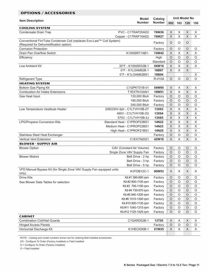
Item Description Model Number
Catalog Number
Unit Model No092 102 120 150
COOLING SYSTEMCondensate Drain Trap PVC - C1TRAP20AD2 76W26 X X X X
Copper - C1TRAP10AD2 76W27 X X X XConventional Fin/Tube Condenser Coil (replaces Eco-Last™ Coil System) (Required for Dehumidification option) Factory O O O
Corrosion Protection Factory O O O ODrain Pan Overflow Switch K1SNSR71AB1- 74W42 X X X XEfficiency High O O O O
Standard O O O OLow Ambient Kit 30°F - K1SNSR33B-1 54W16 X X X X
0°F - K1LOAM62B-1 18B87 X X X0°F - K1LOAM62BS1 18B94 X
Refrigerant Type R-410A O O O OHEATING SYSTEMBottom Gas Piping Kit C1GPKT01B-01 54W95 X X X XCombustion Air Intake Extensions T1EXTN10AN1 19W51 X X X XGas Heat Input 130,000 Btuh Factory O O O O
180,000 Btuh Factory O O O O240,000 Btuh Factory O O O O
Low Temperature Vestibule Heater 208/230V-3ph - C1LTVH10B-2Y 13X63 X X X X460V - C1LTVH10B-2G 13X64 X X X X575V - C1LTVH10B-2J 13X65 X X X X
LPG/Propane Conversion Kits Standard Heat - C1PROP23BS1 14N22 X X X XMedium Heat - C1PROP22BS1 14N23 X X X X
High Heat - C1PROP21BS1 14N25 X X X XStainless Steel Heat Exchanger Factory O O O OVertical Vent Extension C1EXTN2021 42W16 X X X XBLOWER - SUPPLY AIRBlower Option CAV (Constant Air Volume) Factory O O O O
Single Zone VAV Supply Fan Factory O O O OBlower Motors Belt Drive - 2 hp Factory O O O O
Belt Drive - 3 hp Factory O O O OBelt Drive - 5 hp Factory O O O O
VFD Manual Bypass Kit (for Single Zone VAV Supply Fan equipped units only) KVFDB12C-1 90W53 X X X X
Drive KitsSee Blower Data Tables for selection
Kit #1 590-890 rpm Factory O O O OKit #2 800-1105 rpm Factory O O O OKit #3 795-1195 rpm Factory O O O O
Kit #4 730-970 rpm Factory O O O OKit #5 940-1200 rpm Factory O O O O
Kit #6 1015-1300 rpm Factory O O O OKit #10 900-1135 rpm Factory O O O O
Kit #11 1040-1315 rpm Factory O O O OKit #12 1125-1425 rpm Factory O O O O
CABINETCombination Coil/Hail Guards C1GARD52B-1 13T05 X X X XHinged Access Panels Factory O O O OHorizontal Discharge Kit K1HECK00B-1 51W25 X X X X
NOTE - Catalog and model numbers shown are for ordering field installed accessories.OX - Configure To Order (Factory Installed) or Field InstalledO = Configure To Order (Factory Installed)X = Field Installed
K-Series Packaged Gas / Electric 7.5 to 12.5 Ton / Page 12
OPTIONS / ACCESSORIES
Item Description Model Number
Catalog Number
Unit Model No092 102 120 150
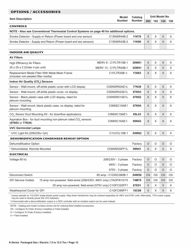
CONTROLS
NOTE - Also see Conventional Thermostat Control Systems on page 40 for additional options.
Smoke Detector - Supply or Return (Power board and one sensor) C1SNSR44B-2 11K76 X X X X
Smoke Detector - Supply and Return (Power board and two sensors) C1SNSR43B-2 11K80 X X X X
INDOOR AIR QUALITY
Air Filters
High Efficiency Air Filters20 x 25 x 2 (Order 4 per unit)
MERV 8 - C1FLTR15B-1 50W61 X X X X
MERV 13 - C1FLTR40B-1 52W41 X X X X
Replacement Media Filter With Metal Mesh Frame (includes non-pleated filter media)
C1FLTR30B-1- Y3063 X X X X
Indoor Air Quality (CO2) Sensors
Sensor - Wall-mount, off-white plastic cover with LCD display C0SNSR50AE1L 77N39 X X X X
Sensor - Wall-mount, off-white plastic cover, no display C0SNSR52AE1L 87N53 X X X X
Sensor - Black plastic case with LCD display, rated for plenum mounting
C0SNSR51AE1L 87N52 X X X X
Sensor - Wall-mount, black plastic case, no display, rated for plenum mounting
C0MISC19AE1 87N54 X X X X
CO2 Sensor Duct Mounting Kit - for downflow applications C0MISC19AE1- 85L43 X X X X
Aspiration Box - for duct mounting non-plenum rated CO2 sensors (87N53 or 77N39) C0MISC16AE1- 90N43 X X X X
UVC Germicidal Lamps1 UVC Light Kit (208/230v-1ph) C1UVCL10B-1 54W62 X X X X
dehumidification condenser reheat option
Dehumidification Option Factory O O O O2 Dehumidistat, Remote Mounted C0SNSR30FF1L 99N41 X X X X
ELECTRICAL
Voltage 60 hz 208/230V - 3 phase Factory O O O O
460V - 3 phase Factory O O O O
575V - 3 phase Factory O O O O
Disconnect Switch 80 amp - C1DISC080B-1 54W56 OX OX OX OX
GFI Service Outlets 15 amp non-powered, field-wired (208/230V, 460V only) LTAGFIK10/15 74M70 OX OX OX OX
20 amp non-powered, field-wired (575V only) C1GFCI20FF1 67E01 X X X X
Weatherproof Cover for GFI C1GFCI99FF1 10C89 X X X X1 Lamps operate on 110-230V single-phase power supply. Step-down transformer may be ordered separately for 460V and 575V units. Alternately, 110V power supply
may be used to directly power the UVC ballast(s)2 A thermostat with a dehumidification output or a DDC controller with an isolated output can be used instead.
NOTE - Catalog and model numbers shown are for ordering field installed accessories.OX - Configure To Order (Factory Installed) or Field InstalledO = Configure To Order (Factory Installed)X = Field Installed
K-Series Packaged Gas / Electric 7.5 to 12.5 Ton / Page 13
OPTIONS / ACCESSORIES
Item Description Model Number
Catalog Number
Unit Model No092 102 120 150
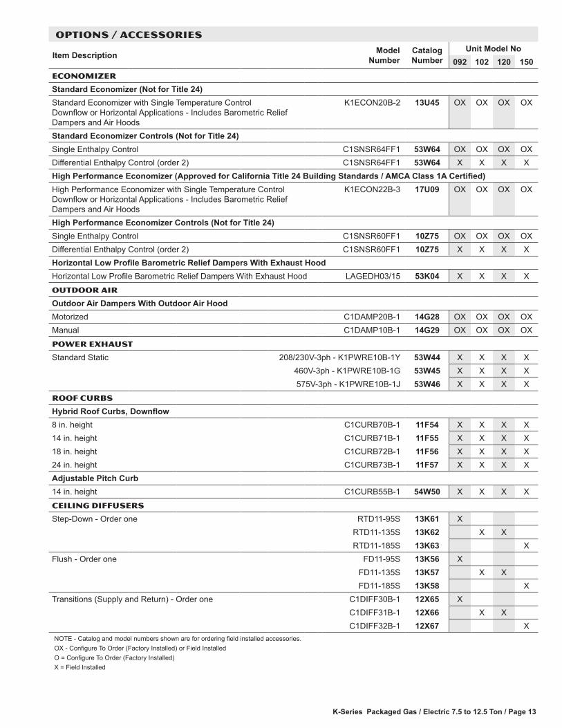
ECONOMIZER
Standard Economizer (Not for Title 24)Standard Economizer with Single Temperature Control Downflow or Horizontal Applications - Includes Barometric Relief Dampers and Air Hoods
K1ECON20B-2 13U45 OX OX OX OX
Standard Economizer Controls (Not for Title 24)Single Enthalpy Control C1SNSR64FF1 53W64 OX OX OX OXDifferential Enthalpy Control (order 2) C1SNSR64FF1 53W64 X X X XHigh Performance Economizer (Approved for California Title 24 Building Standards / AMCA Class 1A Certified)High Performance Economizer with Single Temperature Control Downflow or Horizontal Applications - Includes Barometric Relief Dampers and Air Hoods
K1ECON22B-3 17U09 OX OX OX OX
High Performance Economizer Controls (Not for Title 24)Single Enthalpy Control C1SNSR60FF1 10Z75 OX OX OX OXDifferential Enthalpy Control (order 2) C1SNSR60FF1 10Z75 X X X XHorizontal Low Profile Barometric Relief Dampers With Exhaust HoodHorizontal Low Profile Barometric Relief Dampers With Exhaust Hood LAGEDH03/15 53K04 X X X XOUTDOOR AIR
Outdoor Air Dampers With Outdoor Air HoodMotorized C1DAMP20B-1 14G28 OX OX OX OXManual C1DAMP10B-1 14G29 OX OX OX OXPOWER EXHAUST
Standard Static 208/230V-3ph - K1PWRE10B-1Y 53W44 X X X X460V-3ph - K1PWRE10B-1G 53W45 X X X X575V-3ph - K1PWRE10B-1J 53W46 X X X X
ROOF CURBS
Hybrid Roof Curbs, Downflow8 in. height C1CURB70B-1 11F54 X X X X14 in. height C1CURB71B-1 11F55 X X X X18 in. height C1CURB72B-1 11F56 X X X X24 in. height C1CURB73B-1 11F57 X X X XAdjustable Pitch Curb14 in. height C1CURB55B-1 54W50 X X X XCEILING DIFFUSERS
Step-Down - Order one RTD11-95S 13K61 XRTD11-135S 13K62 X XRTD11-185S 13K63 X
Flush - Order one FD11-95S 13K56 XFD11-135S 13K57 X XFD11-185S 13K58 X
Transitions (Supply and Return) - Order one C1DIFF30B-1 12X65 XC1DIFF31B-1 12X66 X XC1DIFF32B-1 12X67 X
NOTE - Catalog and model numbers shown are for ordering field installed accessories.OX - Configure To Order (Factory Installed) or Field InstalledO = Configure To Order (Factory Installed)X = Field Installed
K-Series Packaged Gas / Electric 7.5 to 12.5 Ton / Page 14
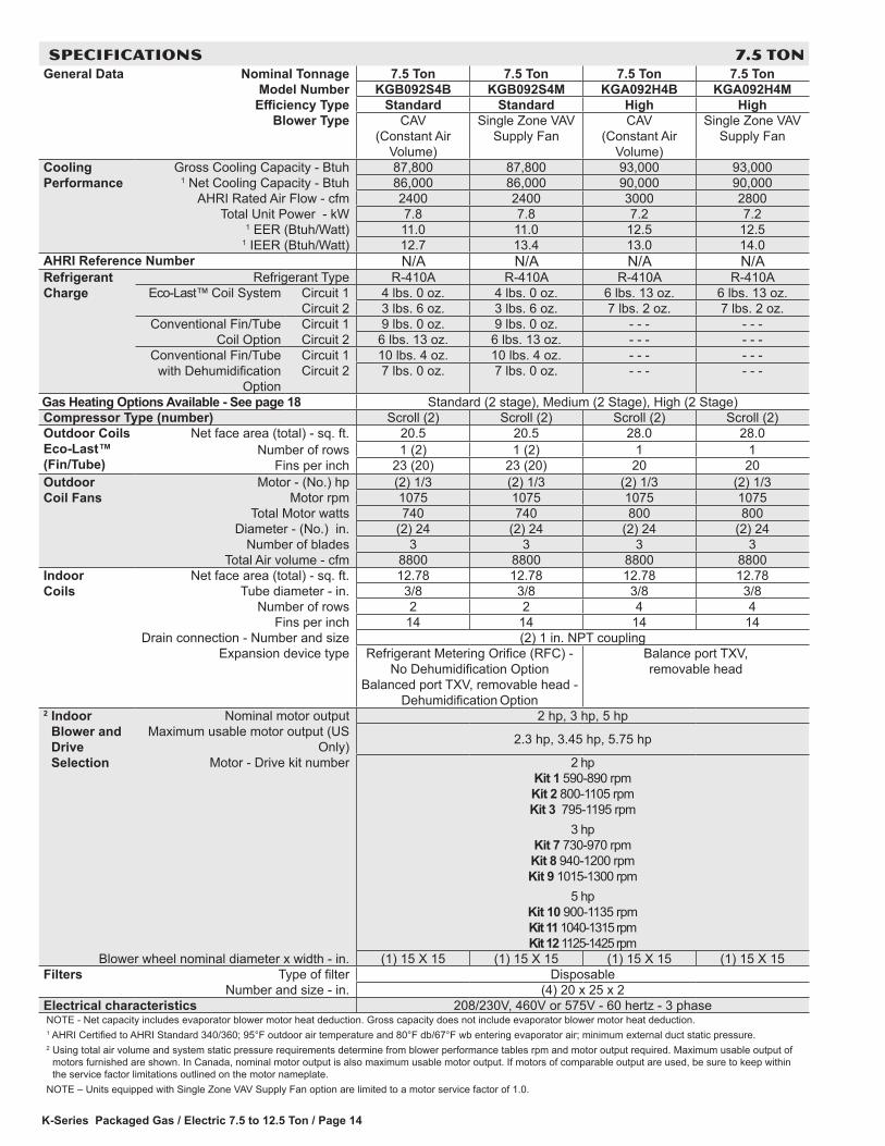
SPECIFICATIONS 7.5 TONGeneral Data Nominal Tonnage 7.5 Ton 7.5 Ton 7.5 Ton 7.5 Ton
Model Number KGB092S4B KGB092S4M KGA092H4B KGA092H4MEfficiency Type Standard Standard High High
Blower Type CAV (Constant Air
Volume)
Single Zone VAV Supply Fan
CAV (Constant Air
Volume)
Single Zone VAV Supply Fan
Cooling Performance
Gross Cooling Capacity - Btuh 87,800 87,800 93,000 93,0001 Net Cooling Capacity - Btuh 86,000 86,000 90,000 90,000
AHRI Rated Air Flow - cfm 2400 2400 3000 2800Total Unit Power - kW 7.8 7.8 7.2 7.2
1 EER (Btuh/Watt) 11.0 11.0 12.5 12.51 IEER (Btuh/Watt) 12.7 13.4 13.0 14.0
AHRI Reference Number N/A N/A N/A N/ARefrigerant Charge
Refrigerant Type R-410A R-410A R-410A R-410A Eco-Last™ Coil System Circuit 1 4 lbs. 0 oz. 4 lbs. 0 oz. 6 lbs. 13 oz. 6 lbs. 13 oz.
Circuit 2 3 lbs. 6 oz. 3 lbs. 6 oz. 7 lbs. 2 oz. 7 lbs. 2 oz.Conventional Fin/Tube
Coil OptionCircuit 1 9 lbs. 0 oz. 9 lbs. 0 oz. - - - - - -Circuit 2 6 lbs. 13 oz. 6 lbs. 13 oz. - - - - - -
Conventional Fin/Tube with Dehumidification
Option
Circuit 1 10 lbs. 4 oz. 10 lbs. 4 oz. - - - - - -Circuit 2 7 lbs. 0 oz. 7 lbs. 0 oz. - - - - - -
Gas Heating Options Available - See page 18 Standard (2 stage), Medium (2 Stage), High (2 Stage)Compressor Type (number) Scroll (2) Scroll (2) Scroll (2) Scroll (2)Outdoor Coils Eco-Last™ (Fin/Tube)
Net face area (total) - sq. ft. 20.5 20.5 28.0 28.0Number of rows 1 (2) 1 (2) 1 1
Fins per inch 23 (20) 23 (20) 20 20Outdoor Coil Fans
Motor - (No.) hp (2) 1/3 (2) 1/3 (2) 1/3 (2) 1/3Motor rpm 1075 1075 1075 1075
Total Motor watts 740 740 800 800Diameter - (No.) in. (2) 24 (2) 24 (2) 24 (2) 24
Number of blades 3 3 3 3Total Air volume - cfm 8800 8800 8800 8800
Indoor Coils
Net face area (total) - sq. ft. 12.78 12.78 12.78 12.78Tube diameter - in. 3/8 3/8 3/8 3/8
Number of rows 2 2 4 4Fins per inch 14 14 14 14
Drain connection - Number and size (2) 1 in. NPT couplingExpansion device type Refrigerant Metering Orifice (RFC) -
No Dehumidification Option Balanced port TXV, removable head -
Dehumidification Option
Balance port TXV, removable head
2 Indoor Blower and Drive Selection
Nominal motor output 2 hp, 3 hp, 5 hpMaximum usable motor output (US
Only) 2.3 hp, 3.45 hp, 5.75 hp
Motor - Drive kit number 2 hp Kit 1 590-890 rpm Kit 2 800-1105 rpm Kit 3 795-1195 rpm
3 hp Kit 7 730-970 rpm Kit 8 940-1200 rpm Kit 9 1015-1300 rpm
5 hp Kit 10 900-1135 rpm Kit 11 1040-1315 rpm Kit 12 1125-1425 rpm
Blower wheel nominal diameter x width - in. (1) 15 X 15 (1) 15 X 15 (1) 15 X 15 (1) 15 X 15Filters Type of filter Disposable
Number and size - in. (4) 20 x 25 x 2Electrical characteristics 208/230V, 460V or 575V - 60 hertz - 3 phaseNOTE - Net capacity includes evaporator blower motor heat deduction. Gross capacity does not include evaporator blower motor heat deduction.1 AHRI Certified to AHRI Standard 340/360; 95°F outdoor air temperature and 80°F db/67°F wb entering evaporator air; minimum external duct static pressure.2 Using total air volume and system static pressure requirements determine from blower performance tables rpm and motor output required. Maximum usable output of
motors furnished are shown. In Canada, nominal motor output is also maximum usable motor output. If motors of comparable output are used, be sure to keep within the service factor limitations outlined on the motor nameplate.
NOTE – Units equipped with Single Zone VAV Supply Fan option are limited to a motor service factor of 1.0.

K-Series Packaged Gas / Electric 7.5 to 12.5 Ton / Page 15
SPECIFICATIONS 8.5 TONGeneral Data Nominal Tonnage 8.5 Ton 8.5 Ton 8.5 Ton 8.5 Ton
Model Number KGB102S4B KGB102S4M KGA102H4B KGA102H4MEfficiency Type Standard Standard High High
Blower Type CAV (Constant Air
Volume)
Single Zone VAV Supply Fan
CAV (Constant Air
Volume)
Single Zone VAV Supply Fan
Cooling Performance
Gross Cooling Capacity - Btuh 99,600 99,600 103,800 103,8001 Net Cooling Capacity - Btuh 97,000 97,000 100,000 100,000
AHRI Rated Air Flow - cfm 2800 2800 3400 3400Total Unit Power - kW 8.8 8.8 8.2 8.2
1 EER (Btuh/Watt) 11.0 11.0 12.2 12.21 IEER (Btuh/Watt) 12.7 13.6 12.9 14.0
AHRI Reference Number N/A N/A N/A N/ARefrigerant Charge
Refrigerant Type R-410A R-410A R-410A R-410A Eco-Last™ Coil System Circuit 1 4 lbs. 5 oz. 4 lbs. 5 oz. 6 lbs. 8 oz. 6 lbs. 8 oz.
Circuit 2 4 lbs. 3 oz. 4 lbs. 3 oz. 6 lbs. 15 oz. 6 lbs. 15 oz.Conventional Fin/Tube
Coil OptionCircuit 1 9 lbs. 3 oz. 9 lbs. 3 oz. - - - - - -Circuit 2 7 lbs. 14 oz. 7 lbs. 14 oz. - - - - - -
Conventional Fin/Tube with Dehumidification
Option
Circuit 1 9 lbs. 8 oz. 9 lbs. 8 oz. - - - - - -Circuit 2 9 lbs. 4 oz. 9 lbs. 4 oz. - - - - - -
Gas Heating Options Available - See page 18 Standard (2 stage), Medium (2 Stage), High (2 Stage)Compressor Type (number) Scroll (2) Scroll (2) Scroll (2) Scroll (2)Outdoor Coils (Fin/Tube)
Net face area (total) - sq. ft. 20.5 20.5 28.0 28.0Number of rows 1 (2) 1 (2) 1 1
Fins per inch 23 (20) 23 (20) 20 20Outdoor Coil Fans
Motor - (No.) hp (2) 1/3 (2) 1/3 (2) 1/3 (2) 1/3Motor rpm 1075 1075 1075 1075
Total Motor watts 740 740 800 800Diameter - (No.) in. (2) 24 (2) 24 (2) 24 (2) 24
Number of blades 3 3 3 3Total Air volume - cfm 8800 8800 8800 8800
Indoor Coils
Net face area (total) - sq. ft. 12.78 12.78 12.78 12.78Tube diameter - in. 3/8 3/8 3/8 3/8
Number of rows 3 3 4 4Fins per inch 14 14 14 14
Drain connection - Number and size (2) 1 in. NPT couplingExpansion device type Refrigerant Metering Orifice (RFC) -
No Dehumidification Option Balanced port TXV, removable head
-Dehumidification Option
Balance port TXV, removable head
2 Indoor Blower and Drive Selection
Nominal motor output 2 hp, 3 hp, 5 hpMaximum usable motor output (US
Only) 2.3 hp, 3.45 hp, 5.75 hp
Motor - Drive kit number 2 hp Kit 1 590-890 rpm Kit 2 800-1105 rpm Kit 3 795-1195 rpm
3 hp Kit 7 730-970 rpm Kit 8 940-1200 rpm Kit 9 1015-1300 rpm
5 hp Kit 10 900-1135 rpm Kit 11 1040-1315 rpm Kit 12 1125-1425 rpm
Blower wheel nominal diameter x width - in. (1) 15 X 15 (1) 15 X 15 (1) 15 X 15 (1) 15 X 15Filters Type of filter Disposable
Number and size - in. (4) 20 x 25 x 2Electrical characteristics 208/230V, 460V or 575V - 60 hertz - 3 phaseNOTE - Net capacity includes evaporator blower motor heat deduction. Gross capacity does not include evaporator blower motor heat deduction.1 AHRI Certified to AHRI Standard 340/360; 95°F outdoor air temperature and 80°F db/67°F wb entering evaporator air; minimum external duct static pressure.2 Using total air volume and system static pressure requirements determine from blower performance tables rpm and motor output required. Maximum usable output of
motors furnished are shown. In Canada, nominal motor output is also maximum usable motor output. If motors of comparable output are used, be sure to keep within the service factor limitations outlined on the motor nameplate.
NOTE – Units equipped with Single Zone VAV Supply Fan option are limited to a motor service factor of 1.0.
K-Series Packaged Gas / Electric 7.5 to 12.5 Ton / Page 16
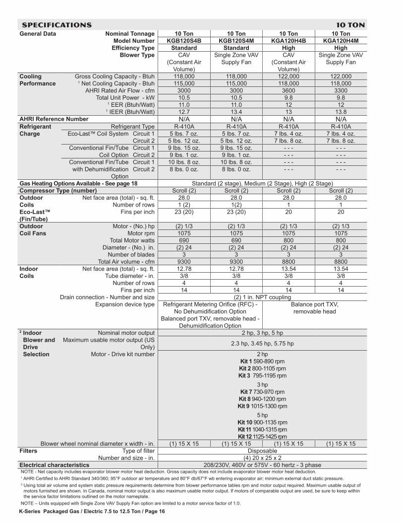
SPECIFICATIONS 10 TONGeneral Data Nominal Tonnage 10 Ton 10 Ton 10 Ton 10 Ton
Model Number KGB120S4B KGB120S4M KGA120H4B KGA120H4MEfficiency Type Standard Standard High High
Blower Type CAV (Constant Air
Volume)
Single Zone VAV Supply Fan
CAV (Constant Air
Volume)
Single Zone VAV Supply Fan
Cooling Performance
Gross Cooling Capacity - Btuh 118,000 118,000 122,000 122,0001 Net Cooling Capacity - Btuh 115,000 115,000 118,000 118,000
AHRI Rated Air Flow - cfm 3000 3000 3600 3300Total Unit Power - kW 10.5 10.5 9.8 9.8
1 EER (Btuh/Watt) 11.0 11.0 12 121 IEER (Btuh/Watt) 12.7 13.4 13 13.8
AHRI Reference Number N/A N/A N/A N/ARefrigerant Charge
Refrigerant Type R-410A R-410A R-410A R-410A Eco-Last™ Coil System Circuit 1 5 lbs. 7 oz. 5 lbs. 7 oz. 7 lbs. 4 oz. 7 lbs. 4 oz.
Circuit 2 5 lbs. 12 oz. 5 lbs. 12 oz. 7 lbs. 8 oz. 7 lbs. 8 oz.Conventional Fin/Tube
Coil OptionCircuit 1 9 lbs. 15 oz. 9 lbs. 15 oz. - - - - - -Circuit 2 9 lbs. 1 oz. 9 lbs. 1 oz. - - - - - -
Conventional Fin/Tube with Dehumidification
Option
Circuit 1 10 lbs. 8 oz. 10 lbs. 8 oz. - - - - - -Circuit 2 8 lbs. 0 oz. 8 lbs. 0 oz. - - - - - -
Gas Heating Options Available - See page 18 Standard (2 stage), Medium (2 Stage), High (2 Stage)Compressor Type (number) Scroll (2) Scroll (2) Scroll (2) Scroll (2)Outdoor Coils Eco-Last™ (Fin/Tube)
Net face area (total) - sq. ft. 28.0 28.0 28.0 28.0Number of rows 1 (2) 1(2) 1 1
Fins per inch 23 (20) 23 (20) 20 20
Outdoor Coil Fans
Motor - (No.) hp (2) 1/3 (2) 1/3 (2) 1/3 (2) 1/3Motor rpm 1075 1075 1075 1075
Total Motor watts 690 690 800 800Diameter - (No.) in. (2) 24 (2) 24 (2) 24 (2) 24
Number of blades 3 3 3 3Total Air volume - cfm 9300 9300 8800 8800
Indoor Coils
Net face area (total) - sq. ft. 12.78 12.78 13.54 13.54Tube diameter - in. 3/8 3/8 3/8 3/8
Number of rows 4 4 4 4Fins per inch 14 14 14 14
Drain connection - Number and size (2) 1 in. NPT couplingExpansion device type Refrigerant Metering Orifice (RFC) -
No Dehumidification Option Balanced port TXV, removable head -
Dehumidification Option
Balance port TXV, removable head
2 Indoor Blower and Drive Selection
Nominal motor output 2 hp, 3 hp, 5 hpMaximum usable motor output (US
Only) 2.3 hp, 3.45 hp, 5.75 hp
Motor - Drive kit number 2 hp Kit 1 590-890 rpm Kit 2 800-1105 rpm Kit 3 795-1195 rpm
3 hp Kit 7 730-970 rpm Kit 8 940-1200 rpm Kit 9 1015-1300 rpm
5 hp Kit 10 900-1135 rpm Kit 11 1040-1315 rpm Kit 12 1125-1425 rpm
Blower wheel nominal diameter x width - in. (1) 15 X 15 (1) 15 X 15 (1) 15 X 15 (1) 15 X 15Filters Type of filter Disposable
Number and size - in. (4) 20 x 25 x 2Electrical characteristics 208/230V, 460V or 575V - 60 hertz - 3 phaseNOTE - Net capacity includes evaporator blower motor heat deduction. Gross capacity does not include evaporator blower motor heat deduction.1 AHRI Certified to AHRI Standard 340/360; 95°F outdoor air temperature and 80°F db/67°F wb entering evaporator air; minimum external duct static pressure.2 Using total air volume and system static pressure requirements determine from blower performance tables rpm and motor output required. Maximum usable output of
motors furnished are shown. In Canada, nominal motor output is also maximum usable motor output. If motors of comparable output are used, be sure to keep within the service factor limitations outlined on the motor nameplate.
NOTE – Units equipped with Single Zone VAV Supply Fan option are limited to a motor service factor of 1.0.
K-Series Packaged Gas / Electric 7.5 to 12.5 Ton / Page 17
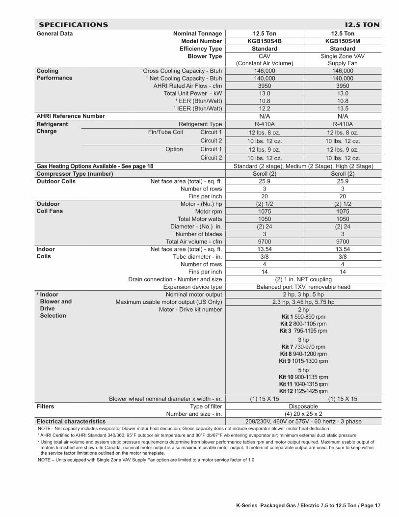
SPECIFICATIONS 12.5 TONGeneral Data Nominal Tonnage 12.5 Ton 12.5 Ton
Model Number KGB150S4B KGB150S4MEfficiency Type Standard Standard
Blower Type CAV (Constant Air Volume)
Single Zone VAV Supply Fan
Cooling Performance
Gross Cooling Capacity - Btuh 146,000 146,0001 Net Cooling Capacity - Btuh 140,000 140,000
AHRI Rated Air Flow - cfm 3950 3950Total Unit Power - kW 13.0 13.0
1 EER (Btuh/Watt) 10.8 10.81 IEER (Btuh/Watt) 12.2 13.5
AHRI Reference Number N/A N/ARefrigerant Charge
Refrigerant Type R-410A R-410AFin/Tube Coil Circuit 1 12 lbs. 8 oz. 12 lbs. 8 oz.
Circuit 2 10 lbs. 12 oz. 10 lbs. 12 oz. Option Circuit 1 12 lbs. 9 oz. 12 lbs. 9 oz.
Circuit 2 10 lbs. 12 oz. 10 lbs. 12 oz. Gas Heating Options Available - See page 18 Standard (2 stage), Medium (2 Stage), High (2 Stage)Compressor Type (number) Scroll (2) Scroll (2)Outdoor Coils Net face area (total) - sq. ft. 25.9 25.9
Number of rows 3 3Fins per inch 20 20
Outdoor Coil Fans
Motor - (No.) hp (2) 1/2 (2) 1/2Motor rpm 1075 1075
Total Motor watts 1050 1050Diameter - (No.) in. (2) 24 (2) 24
Number of blades 3 3Total Air volume - cfm 9700 9700
Indoor Coils
Net face area (total) - sq. ft. 13.54 13.54Tube diameter - in. 3/8 3/8
Number of rows 4 4Fins per inch 14 14
Drain connection - Number and size (2) 1 in. NPT couplingExpansion device type Balanced port TXV, removable head
2 Indoor Blower and Drive Selection
Nominal motor output 2 hp, 3 hp, 5 hpMaximum usable motor output (US Only) 2.3 hp, 3.45 hp, 5.75 hp
Motor - Drive kit number 2 hp Kit 1 590-890 rpm Kit 2 800-1105 rpm Kit 3 795-1195 rpm
3 hp Kit 7 730-970 rpm Kit 8 940-1200 rpm Kit 9 1015-1300 rpm
5 hp Kit 10 900-1135 rpm Kit 11 1040-1315 rpm Kit 12 1125-1425 rpm
Blower wheel nominal diameter x width - in. (1) 15 X 15 (1) 15 X 15Filters Type of filter Disposable
Number and size - in. (4) 20 x 25 x 2Electrical characteristics 208/230V, 460V or 575V - 60 hertz - 3 phaseNOTE - Net capacity includes evaporator blower motor heat deduction. Gross capacity does not include evaporator blower motor heat deduction.1 AHRI Certified to AHRI Standard 340/360; 95°F outdoor air temperature and 80°F db/67°F wb entering evaporator air; minimum external duct static pressure.2 Using total air volume and system static pressure requirements determine from blower performance tables rpm and motor output required. Maximum usable output of
motors furnished are shown. In Canada, nominal motor output is also maximum usable motor output. If motors of comparable output are used, be sure to keep within the service factor limitations outlined on the motor nameplate.
NOTE – Units equipped with Single Zone VAV Supply Fan option are limited to a motor service factor of 1.0.
K-Series Packaged Gas / Electric 7.5 to 12.5 Ton / Page 18
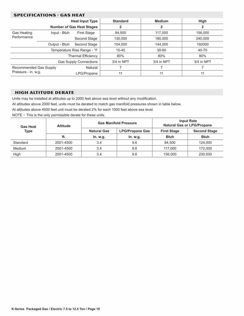
SPECIFICATIONS - GAS HEATHeat Input Type Standard Medium High
Number of Gas Heat Stages 2 2 2Gas Heating Performance
Input - Btuh First Stage 84,500 117,000 156,000Second Stage 130,000 180,000 240,000
Output - Btuh Second Stage 104,000 144,000 192000Temperature Rise Range - °F 15-45 30-60 40-70
Thermal Efficiency 80% 80% 80%Gas Supply Connections 3/4 in NPT 3/4 in NPT 3/4 in NPT
Recommended Gas Supply Pressure - in. w.g.
Natural 7 7 7LPG/Propane 11 11 11
HIGH ALTITUDE DERATE Units may be installed at altitudes up to 2000 feet above sea level without any modification.At altitudes above 2000 feet, units must be derated to match gas manifold pressures shown in table below.At altitudes above 4500 feet unit must be derated 2% for each 1000 feet above sea level.NOTE − This is the only permissible derate for these units.
Gas Heat Type
Altitude Gas Manifold Pressure Input Rate
Natural Gas or LPG/PropaneNatural Gas LPG/Propane Gas First Stage Second Stage
ft. In. w.g. In. w.g. Btuh Btuh Standard 2001-4500 3.4 9.6 84,500 124,000 Medium 2001-4500 3.4 9.6 117,000 172,000 High 2001-4500 3.4 9.6 156,000 230,000

K-Series Packaged Gas / Electric 7.5 to 12.5 Ton / Page 19
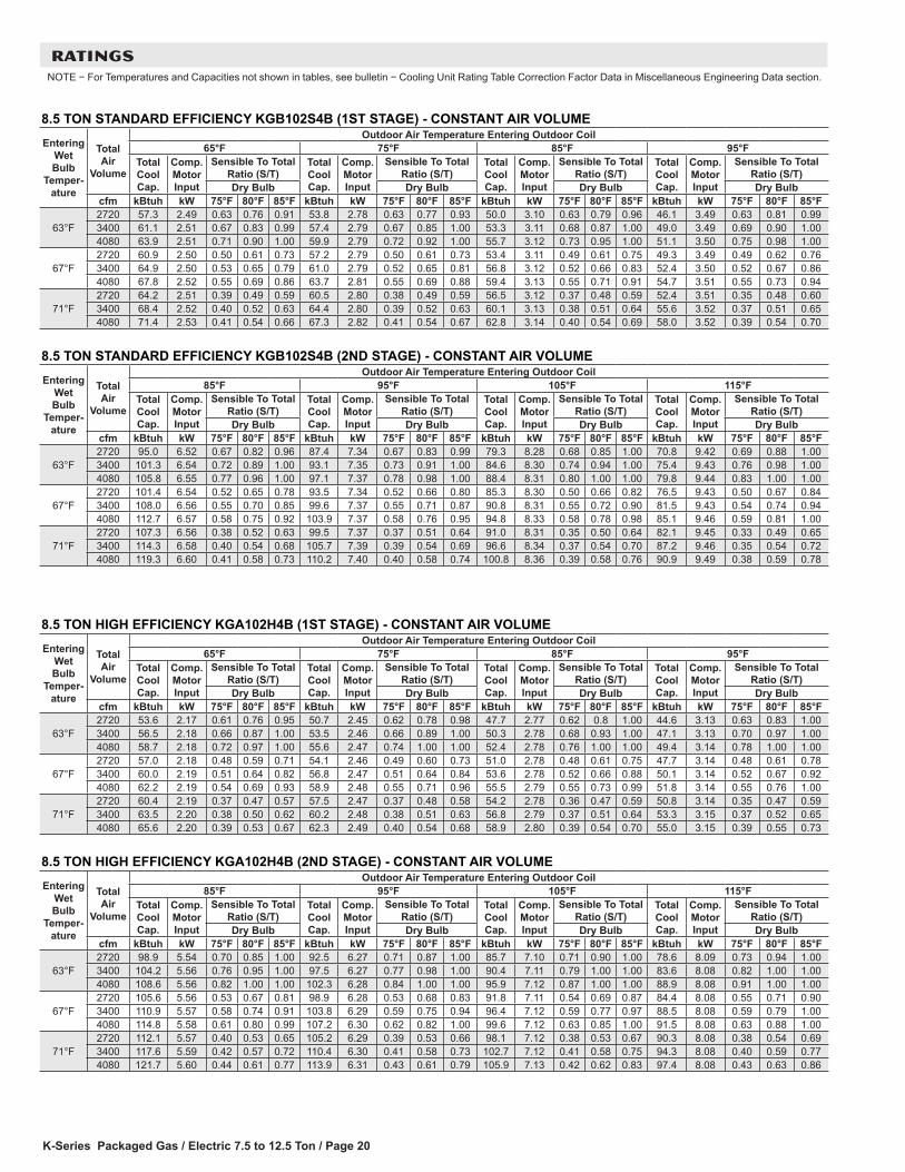
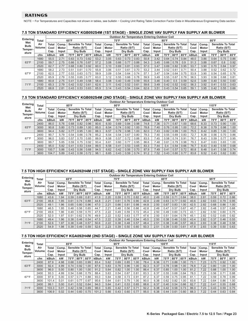
RATINGSNOTE − For Temperatures and Capacities not shown in tables, see bulletin − Cooling Unit Rating Table Correction Factor Data in Miscellaneous Engineering Data section.
7.5 TON STANDARD EFFICIENCY KGB092S4B (1ST STAGE) - CONSTANT AIR VOLUMEEntering
Wet Bulb
Temper-ature
Total Air
Volume
Outdoor Air Temperature Entering Outdoor Coil65°F 75°F 85°F 95°F
Total Cool Cap.
Comp. Motor Input
Sensible To Total Ratio (S/T)
Total Cool Cap.
Comp. Motor Input
Sensible To Total Ratio (S/T)
Total Cool Cap.
Comp. Motor Input
Sensible To Total Ratio (S/T)
Total Cool Cap.
Comp. Motor Input
Sensible To Total Ratio (S/T)
Dry Bulb Dry Bulb Dry Bulb Dry Bulbcfm kBtuh kW 75°F 80°F 85°F kBtuh kW 75°F 80°F 85°F kBtuh kW 75°F 80°F 85°F kBtuh kW 75°F 80°F 85°F
63°F2400 63.6 2.73 0.66 0.77 0.90 60.9 3.06 0.66 0.78 0.91 57.8 3.43 0.67 0.80 0.93 54.5 3.86 0.68 0.82 0.963000 67.1 2.76 0.69 0.83 0.96 64.3 3.08 0.70 0.84 0.98 61.1 3.45 0.71 0.86 0.99 57.6 3.88 0.72 0.88 1.003600 70.2 2.78 0.72 0.88 1.00 67.1 3.10 0.73 0.89 1.00 63.7 3.47 0.74 0.91 1.00 60.0 3.90 0.76 0.94 1.00
67°F2400 66.8 2.76 0.53 0.64 0.74 64.0 3.08 0.54 0.64 0.75 60.9 3.45 0.54 0.65 0.76 57.4 3.88 0.54 0.66 0.783000 70.7 2.79 0.55 0.67 0.79 67.5 3.10 0.56 0.67 0.81 64.1 3.47 0.56 0.68 0.82 60.5 3.91 0.56 0.70 0.853600 73.5 2.80 0.57 0.70 0.84 70.2 3.12 0.57 0.71 0.86 66.6 3.49 0.58 0.72 0.88 62.6 3.92 0.58 0.74 0.90
71°F2400 69.7 2.78 0.42 0.52 0.61 66.8 3.10 0.42 0.52 0.62 63.6 3.47 0.41 0.52 0.63 60.1 3.90 0.40 0.53 0.643000 73.9 2.81 0.43 0.54 0.65 70.6 3.12 0.43 0.54 0.65 67.1 3.50 0.42 0.55 0.66 63.3 3.93 0.41 0.55 0.683600 77.0 2.83 0.44 0.56 0.68 73.5 3.14 0.44 0.56 0.69 69.6 3.51 0.41 0.57 0.70 65.6 3.95 0.42 0.57 0.72
7.5 TON STANDARD EFFICIENCY KGB092S4B (2ND STAGE) - CONSTANT AIR VOLUMEEntering
Wet Bulb
Temper-ature
Total Air
Volume
Outdoor Air Temperature Entering Outdoor Coil85°F 95°F 105°F 115°F
Total Cool Cap.
Comp. Motor Input
Sensible To Total Ratio (S/T)
Total Cool Cap.
Comp. Motor Input
Sensible To Total Ratio (S/T)
Total Cool Cap.
Comp. Motor Input
Sensible To Total Ratio (S/T)
Total Cool Cap.
Comp. Motor Input
Sensible To Total Ratio (S/T)
Dry Bulb Dry Bulb Dry Bulb Dry Bulbcfm kBtuh kW 75°F 80°F 85°F kBtuh kW 75°F 80°F 85°F kBtuh kW 75°F 80°F 85°F kBtuh kW 75°F 80°F 85°F
63°F2400 86.0 5.76 0.68 0.82 0.96 80.6 6.50 0.69 0.84 0.98 74.8 7.36 0.71 0.87 1.00 68.6 8.33 0.73 0.90 1.003000 90.8 5.80 0.73 0.89 1.00 85.0 6.54 0.74 0.92 1.00 78.8 7.40 0.76 0.95 1.00 72.2 8.38 0.79 0.98 1.003600 94.4 5.82 0.77 0.95 1.00 88.3 6.57 0.79 0.98 1.00 82.0 7.43 0.82 0.99 1.00 75.5 8.42 0.85 1.00 1.00
67°F2400 90.7 5.79 0.54 0.66 0.78 85.2 6.54 0.54 0.67 0.80 79.3 7.40 0.55 0.69 0.83 72.7 8.38 0.56 0.70 0.863000 96.0 5.83 0.57 0.70 0.85 89.9 6.58 0.57 0.72 0.88 83.5 7.45 0.58 0.74 0.91 76.7 8.43 0.59 0.77 0.953600 99.7 5.85 0.59 0.75 0.92 93.4 6.61 0.60 0.77 0.95 86.6 7.48 0.61 0.79 0.98 79.3 8.47 0.63 0.83 1.00
71°F2400 95.0 5.82 0.41 0.53 0.64 89.5 6.58 0.41 0.53 0.65 83.3 7.44 0.4 0.54 0.66 76.7 8.43 0.40 0.55 0.683000 100.7 5.86 0.43 0.56 0.68 94.5 6.62 0.42 0.56 0.70 87.9 7.49 0.41 0.57 0.72 80.8 8.48 0.41 0.58 0.743600 104.7 5.89 0.43 0.58 0.72 98.1 6.65 0.43 0.59 0.74 91.2 7.52 0.43 0.60 0.77 83.8 8.52 0.43 0.62 0.80
7.5 TON HIGH EFFICIENCY KGA092H4B (1ST STAGE) - CONSTANT AIR VOLUMEEntering
Wet Bulb
Temper-ature
Total Air
Volume
Outdoor Air Temperature Entering Outdoor Coil65°F 75°F 85°F 95°F
Total Cool Cap.
Comp. Motor Input
Sensible To Total Ratio (S/T)
Total Cool Cap.
Comp. Motor Input
Sensible To Total Ratio (S/T)
Total Cool Cap.
Comp. Motor Input
Sensible To Total Ratio (S/T)
Total Cool Cap.
Comp. Motor Input
Sensible To Total Ratio (S/T)
Dry Bulb Dry Bulb Dry Bulb Dry Bulbcfm kBtuh kW 75°F 80°F 85°F kBtuh kW 75°F 80°F 85°F kBtuh kW 75°F 80°F 85°F kBtuh kW 75°F 80°F 85°F
63°F2400 48.2 1.95 0.67 0.80 0.95 46.2 2.21 0.67 0.81 0.97 43.9 2.49 0.68 0.83 0.99 41.7 2.81 0.69 0.85 1.003000 50.8 1.96 0.71 0.88 1.00 48.6 2.21 0.72 0.90 1.00 46.2 2.49 0.74 0.92 1.00 43.7 2.81 0.76 0.96 1.003600 52.8 1.96 0.76 0.96 1.00 50.4 2.22 0.78 0.98 1.00 48.0 2.50 0.80 1.00 1.00 45.6 2.81 0.82 1.00 1.00
67°F2400 51.1 1.96 0.53 0.65 0.76 48.9 2.21 0.53 0.65 0.78 46.6 2.49 0.54 0.66 0.79 44.1 2.81 0.54 0.67 0.813000 53.8 1.97 0.55 0.69 0.84 51.4 2.22 0.56 0.70 0.86 48.9 2.50 0.57 0.71 0.88 46.4 2.82 0.58 0.73 0.923600 55.7 1.97 0.59 0.74 0.91 53.3 2.22 0.60 0.76 0.95 50.6 2.50 0.61 0.78 0.97 47.7 2.82 0.61 0.80 1.00
71°F2400 54.2 1.97 0.41 0.52 0.62 51.9 2.22 0.41 0.52 0.63 49.5 2.50 0.41 0.52 0.64 47.1 2.82 0.41 0.53 0.653000 56.7 1.98 0.41 0.54 0.67 54.3 2.23 0.42 0.55 0.68 51.7 2.51 0.42 0.56 0.69 48.9 2.82 0.42 0.57 0.713600 58.6 1.98 0.43 0.57 0.71 56.1 2.23 0.44 0.58 0.73 53.4 2.51 0.43 0.60 0.75 50.6 2.83 0.43 0.61 0.78
7.5 TON HIGH EFFICIENCY KGA092H4B (2ND STAGE) - CONSTANT AIR VOLUMEEntering
Wet Bulb
Temper-ature
Total Air
Volume
Outdoor Air Temperature Entering Outdoor Coil85°F 95°F 105°F 115°F
Total Cool Cap.
Comp. Motor Input
Sensible To Total Ratio (S/T)
Total Cool Cap.
Comp. Motor Input
Sensible To Total Ratio (S/T)
Total Cool Cap.
Comp. Motor Input
Sensible To Total Ratio (S/T)
Total Cool Cap.
Comp. Motor Input
Sensible To Total Ratio (S/T)
Dry Bulb Dry Bulb Dry Bulb Dry Bulbcfm kBtuh kW 75°F 80°F 85°F kBtuh kW 75°F 80°F 85°F kBtuh kW 75°F 80°F 85°F kBtuh kW 75°F 80°F 85°F
63°F2400 87.9 4.98 0.68 0.83 0.99 83.4 5.62 0.69 0.85 1.00 78.4 6.36 0.71 0.88 1.00 73.1 7.23 0.73 0.92 1.003000 92.4 4.99 0.74 0.92 1.00 87.6 5.63 0.76 0.96 1.00 82.3 6.37 0.78 0.98 1.00 76.8 7.22 0.80 1.00 1.003600 96.0 5.00 0.80 1.00 1.00 91.2 5.64 0.82 1.00 1.00 86.4 6.37 0.85 1.00 1.00 81.2 7.22 0.88 1.00 1.00
67°F2400 93.3 4.99 0.54 0.66 0.79 88.4 5.63 0.54 0.67 0.81 83.3 6.37 0.55 0.68 0.84 78.0 7.23 0.56 0.71 0.883000 97.9 5.00 0.57 0.71 0.88 93.0 5.64 0.58 0.73 0.91 87.2 6.37 0.59 0.75 0.95 81.1 7.22 0.59 0.78 0.993600 101.4 5.01 0.61 0.77 0.97 95.6 5.64 0.61 0.79 1.00 90.0 6.38 0.62 0.82 1.00 83.6 7.22 0.64 0.86 1.00
71°F2400 99.1 5.00 0.41 0.52 0.64 94.0 5.64 0.41 0.53 0.65 88.6 6.37 0.4 0.54 0.66 82.7 7.22 0.41 0.55 0.683000 103.3 5.01 0.42 0.56 0.69 98.0 5.65 0.42 0.57 0.71 92.2 6.38 0.42 0.58 0.73 86.0 7.23 0.43 0.59 0.753600 106.9 5.02 0.44 0.60 0.75 101.2 5.66 0.43 0.60 0.77 95.0 6.38 0.44 0.61 0.8 88.3 7.22 0.44 0.63 0.84
K-Series Packaged Gas / Electric 7.5 to 12.5 Ton / Page 20
RATINGSNOTE − For Temperatures and Capacities not shown in tables, see bulletin − Cooling Unit Rating Table Correction Factor Data in Miscellaneous Engineering Data section.
8.5 TON STANDARD EFFICIENCY KGB102S4B (1ST STAGE) - CONSTANT AIR VOLUMEEntering
Wet Bulb
Temper-ature
Total Air
Volume
Outdoor Air Temperature Entering Outdoor Coil65°F 75°F 85°F 95°F
Total Cool Cap.
Comp. Motor Input
Sensible To Total Ratio (S/T)
Total Cool Cap.
Comp. Motor Input
Sensible To Total Ratio (S/T)
Total Cool Cap.
Comp. Motor Input
Sensible To Total Ratio (S/T)
Total Cool Cap.
Comp. Motor Input
Sensible To Total Ratio (S/T)
Dry Bulb Dry Bulb Dry Bulb Dry Bulbcfm kBtuh kW 75°F 80°F 85°F kBtuh kW 75°F 80°F 85°F kBtuh kW 75°F 80°F 85°F kBtuh kW 75°F 80°F 85°F
63°F2720 57.3 2.49 0.63 0.76 0.91 53.8 2.78 0.63 0.77 0.93 50.0 3.10 0.63 0.79 0.96 46.1 3.49 0.63 0.81 0.993400 61.1 2.51 0.67 0.83 0.99 57.4 2.79 0.67 0.85 1.00 53.3 3.11 0.68 0.87 1.00 49.0 3.49 0.69 0.90 1.004080 63.9 2.51 0.71 0.90 1.00 59.9 2.79 0.72 0.92 1.00 55.7 3.12 0.73 0.95 1.00 51.1 3.50 0.75 0.98 1.00
67°F2720 60.9 2.50 0.50 0.61 0.73 57.2 2.79 0.50 0.61 0.73 53.4 3.11 0.49 0.61 0.75 49.3 3.49 0.49 0.62 0.763400 64.9 2.50 0.53 0.65 0.79 61.0 2.79 0.52 0.65 0.81 56.8 3.12 0.52 0.66 0.83 52.4 3.50 0.52 0.67 0.864080 67.8 2.52 0.55 0.69 0.86 63.7 2.81 0.55 0.69 0.88 59.4 3.13 0.55 0.71 0.91 54.7 3.51 0.55 0.73 0.94
71°F2720 64.2 2.51 0.39 0.49 0.59 60.5 2.80 0.38 0.49 0.59 56.5 3.12 0.37 0.48 0.59 52.4 3.51 0.35 0.48 0.603400 68.4 2.52 0.40 0.52 0.63 64.4 2.80 0.39 0.52 0.63 60.1 3.13 0.38 0.51 0.64 55.6 3.52 0.37 0.51 0.654080 71.4 2.53 0.41 0.54 0.66 67.3 2.82 0.41 0.54 0.67 62.8 3.14 0.40 0.54 0.69 58.0 3.52 0.39 0.54 0.70
8.5 TON STANDARD EFFICIENCY KGB102S4B (2ND STAGE) - CONSTANT AIR VOLUMEEntering
Wet Bulb
Temper-ature
Total Air
Volume
Outdoor Air Temperature Entering Outdoor Coil85°F 95°F 105°F 115°F
Total Cool Cap.
Comp. Motor Input
Sensible To Total Ratio (S/T)
Total Cool Cap.
Comp. Motor Input
Sensible To Total Ratio (S/T)
Total Cool Cap.
Comp. Motor Input
Sensible To Total Ratio (S/T)
Total Cool Cap.
Comp. Motor Input
Sensible To Total Ratio (S/T)
Dry Bulb Dry Bulb Dry Bulb Dry Bulbcfm kBtuh kW 75°F 80°F 85°F kBtuh kW 75°F 80°F 85°F kBtuh kW 75°F 80°F 85°F kBtuh kW 75°F 80°F 85°F
63°F2720 95.0 6.52 0.67 0.82 0.96 87.4 7.34 0.67 0.83 0.99 79.3 8.28 0.68 0.85 1.00 70.8 9.42 0.69 0.88 1.003400 101.3 6.54 0.72 0.89 1.00 93.1 7.35 0.73 0.91 1.00 84.6 8.30 0.74 0.94 1.00 75.4 9.43 0.76 0.98 1.004080 105.8 6.55 0.77 0.96 1.00 97.1 7.37 0.78 0.98 1.00 88.4 8.31 0.80 1.00 1.00 79.8 9.44 0.83 1.00 1.00
67°F2720 101.4 6.54 0.52 0.65 0.78 93.5 7.34 0.52 0.66 0.80 85.3 8.30 0.50 0.66 0.82 76.5 9.43 0.50 0.67 0.843400 108.0 6.56 0.55 0.70 0.85 99.6 7.37 0.55 0.71 0.87 90.8 8.31 0.55 0.72 0.90 81.5 9.43 0.54 0.74 0.944080 112.7 6.57 0.58 0.75 0.92 103.9 7.37 0.58 0.76 0.95 94.8 8.33 0.58 0.78 0.98 85.1 9.46 0.59 0.81 1.00
71°F2720 107.3 6.56 0.38 0.52 0.63 99.5 7.37 0.37 0.51 0.64 91.0 8.31 0.35 0.50 0.64 82.1 9.45 0.33 0.49 0.653400 114.3 6.58 0.40 0.54 0.68 105.7 7.39 0.39 0.54 0.69 96.6 8.34 0.37 0.54 0.70 87.2 9.46 0.35 0.54 0.724080 119.3 6.60 0.41 0.58 0.73 110.2 7.40 0.40 0.58 0.74 100.8 8.36 0.39 0.58 0.76 90.9 9.49 0.38 0.59 0.78
8.5 TON HIGH EFFICIENCY KGA102H4B (1ST STAGE) - CONSTANT AIR VOLUMEEntering
Wet Bulb
Temper-ature
Total Air
Volume
Outdoor Air Temperature Entering Outdoor Coil65°F 75°F 85°F 95°F
Total Cool Cap.
Comp. Motor Input
Sensible To Total Ratio (S/T)
Total Cool Cap.
Comp. Motor Input
Sensible To Total Ratio (S/T)
Total Cool Cap.
Comp. Motor Input
Sensible To Total Ratio (S/T)
Total Cool Cap.
Comp. Motor Input
Sensible To Total Ratio (S/T)
Dry Bulb Dry Bulb Dry Bulb Dry Bulbcfm kBtuh kW 75°F 80°F 85°F kBtuh kW 75°F 80°F 85°F kBtuh kW 75°F 80°F 85°F kBtuh kW 75°F 80°F 85°F
63°F2720 53.6 2.17 0.61 0.76 0.95 50.7 2.45 0.62 0.78 0.98 47.7 2.77 0.62 0.8 1.00 44.6 3.13 0.63 0.83 1.003400 56.5 2.18 0.66 0.87 1.00 53.5 2.46 0.66 0.89 1.00 50.3 2.78 0.68 0.93 1.00 47.1 3.13 0.70 0.97 1.004080 58.7 2.18 0.72 0.97 1.00 55.6 2.47 0.74 1.00 1.00 52.4 2.78 0.76 1.00 1.00 49.4 3.14 0.78 1.00 1.00
67°F2720 57.0 2.18 0.48 0.59 0.71 54.1 2.46 0.49 0.60 0.73 51.0 2.78 0.48 0.61 0.75 47.7 3.14 0.48 0.61 0.783400 60.0 2.19 0.51 0.64 0.82 56.8 2.47 0.51 0.64 0.84 53.6 2.78 0.52 0.66 0.88 50.1 3.14 0.52 0.67 0.924080 62.2 2.19 0.54 0.69 0.93 58.9 2.48 0.55 0.71 0.96 55.5 2.79 0.55 0.73 0.99 51.8 3.14 0.55 0.76 1.00
71°F2720 60.4 2.19 0.37 0.47 0.57 57.5 2.47 0.37 0.48 0.58 54.2 2.78 0.36 0.47 0.59 50.8 3.14 0.35 0.47 0.593400 63.5 2.20 0.38 0.50 0.62 60.2 2.48 0.38 0.51 0.63 56.8 2.79 0.37 0.51 0.64 53.3 3.15 0.37 0.52 0.654080 65.6 2.20 0.39 0.53 0.67 62.3 2.49 0.40 0.54 0.68 58.9 2.80 0.39 0.54 0.70 55.0 3.15 0.39 0.55 0.73
8.5 TON HIGH EFFICIENCY KGA102H4B (2ND STAGE) - CONSTANT AIR VOLUMEEntering
Wet Bulb
Temper-ature
Total Air
Volume
Outdoor Air Temperature Entering Outdoor Coil85°F 95°F 105°F 115°F
Total Cool Cap.
Comp. Motor Input
Sensible To Total Ratio (S/T)
Total Cool Cap.
Comp. Motor Input
Sensible To Total Ratio (S/T)
Total Cool Cap.
Comp. Motor Input
Sensible To Total Ratio (S/T)
Total Cool Cap.
Comp. Motor Input
Sensible To Total Ratio (S/T)
Dry Bulb Dry Bulb Dry Bulb Dry Bulbcfm kBtuh kW 75°F 80°F 85°F kBtuh kW 75°F 80°F 85°F kBtuh kW 75°F 80°F 85°F kBtuh kW 75°F 80°F 85°F
63°F2720 98.9 5.54 0.70 0.85 1.00 92.5 6.27 0.71 0.87 1.00 85.7 7.10 0.71 0.90 1.00 78.6 8.09 0.73 0.94 1.003400 104.2 5.56 0.76 0.95 1.00 97.5 6.27 0.77 0.98 1.00 90.4 7.11 0.79 1.00 1.00 83.6 8.08 0.82 1.00 1.004080 108.6 5.56 0.82 1.00 1.00 102.3 6.28 0.84 1.00 1.00 95.9 7.12 0.87 1.00 1.00 88.9 8.08 0.91 1.00 1.00
67°F2720 105.6 5.56 0.53 0.67 0.81 98.9 6.28 0.53 0.68 0.83 91.8 7.11 0.54 0.69 0.87 84.4 8.08 0.55 0.71 0.903400 110.9 5.57 0.58 0.74 0.91 103.8 6.29 0.59 0.75 0.94 96.4 7.12 0.59 0.77 0.97 88.5 8.08 0.59 0.79 1.004080 114.8 5.58 0.61 0.80 0.99 107.2 6.30 0.62 0.82 1.00 99.6 7.12 0.63 0.85 1.00 91.5 8.08 0.63 0.88 1.00
71°F2720 112.1 5.57 0.40 0.53 0.65 105.2 6.29 0.39 0.53 0.66 98.1 7.12 0.38 0.53 0.67 90.3 8.08 0.38 0.54 0.693400 117.6 5.59 0.42 0.57 0.72 110.4 6.30 0.41 0.58 0.73 102.7 7.12 0.41 0.58 0.75 94.3 8.08 0.40 0.59 0.774080 121.7 5.60 0.44 0.61 0.77 113.9 6.31 0.43 0.61 0.79 105.9 7.13 0.42 0.62 0.83 97.4 8.08 0.43 0.63 0.86

K-Series Packaged Gas / Electric 7.5 to 12.5 Ton / Page 21
RATINGSNOTE − For Temperatures and Capacities not shown in tables, see bulletin − Cooling Unit Rating Table Correction Factor Data in Miscellaneous Engineering Data section.
10 TON STANDARD EFFICIENCY KGB120S4B (1ST STAGE) - CONSTANT AIR VOLUMEEntering
Wet Bulb
Temper-ature
Total Air
Volume
Outdoor Air Temperature Entering Outdoor Coil65°F 75°F 85°F 95°F
Total Cool Cap.
Comp. Motor Input
Sensible To Total Ratio (S/T)
Total Cool Cap.
Comp. Motor Input
Sensible To Total Ratio (S/T)
Total Cool Cap.
Comp. Motor Input
Sensible To Total Ratio (S/T)
Total Cool Cap.
Comp. Motor Input
Sensible To Total Ratio (S/T)
Dry Bulb Dry Bulb Dry Bulb Dry Bulbcfm kBtuh kW 75°F 80°F 85°F kBtuh kW 75°F 80°F 85°F kBtuh kW 75°F 80°F 85°F kBtuh kW 75°F 80°F 85°F
63°F3200 62.2 2.85 0.66 0.80 0.94 58.1 3.21 0.66 0.81 0.96 53.6 3.62 0.66 0.82 0.98 49.0 4.09 0.66 0.84 1.004000 66.2 2.86 0.71 0.87 1.00 61.8 3.23 0.71 0.88 1.00 57.2 3.65 0.71 0.90 1.00 52.4 4.11 0.73 0.93 1.004800 69.2 2.89 0.75 0.94 1.00 64.7 3.24 0.76 0.96 1.00 59.9 3.66 0.78 0.98 1.00 54.9 4.14 0.79 1.00 1.00
67°F3200 66.8 2.87 0.53 0.64 0.76 62.4 3.23 0.52 0.64 0.77 57.9 3.65 0.51 0.64 0.78 53.1 4.12 0.50 0.64 0.804000 70.8 2.88 0.55 0.69 0.83 66.2 3.25 0.55 0.69 0.85 61.3 3.67 0.54 0.69 0.86 56.3 4.15 0.54 0.70 0.894800 73.7 2.89 0.58 0.73 0.90 68.8 3.27 0.57 0.74 0.92 63.9 3.69 0.58 0.75 0.94 58.7 4.17 0.57 0.77 0.97
71°F3200 71.3 2.89 0.41 0.52 0.62 66.9 3.26 0.39 0.51 0.62 62.1 3.68 0.37 0.50 0.62 57.1 4.16 0.36 0.49 0.634000 75.4 2.90 0.42 0.55 0.67 70.7 3.28 0.40 0.54 0.67 65.7 3.70 0.39 0.54 0.68 60.3 4.18 0.38 0.53 0.684800 78.4 2.92 0.43 0.58 0.71 73.4 3.29 0.42 0.57 0.72 68.2 3.72 0.41 0.57 0.73 62.8 4.20 0.40 0.57 0.75
10 TON STANDARD EFFICIENCY KGB120S4B (2ND STAGE) - CONSTANT AIR VOLUMEEntering
Wet Bulb
Temper-ature
Total Air
Volume
Outdoor Air Temperature Entering Outdoor Coil85°F 95°F 105°F 115°F
Total Cool Cap.
Comp. Motor Input
Sensible To Total Ratio (S/T)
Total Cool Cap.
Comp. Motor Input
Sensible To Total Ratio (S/T)
Total Cool Cap.
Comp. Motor Input
Sensible To Total Ratio (S/T)
Total Cool Cap.
Comp. Motor Input
Sensible To Total Ratio (S/T)
Dry Bulb Dry Bulb Dry Bulb Dry Bulbcfm kBtuh kW 75°F 80°F 85°F kBtuh kW 75°F 80°F 85°F kBtuh kW 75°F 80°F 85°F kBtuh kW 75°F 80°F 85°F
63°F3200 114.0 7.38 0.68 0.83 0.98 104.2 8.32 0.68 0.85 1.00 93.9 9.38 0.68 0.87 1.00 83.2 10.57 0.69 0.91 1.004000 121.0 7.42 0.73 0.92 1.00 111.1 8.38 0.74 0.94 1.00 100.5 9.44 0.76 0.97 1.00 89.4 10.64 0.78 1.00 1.004800 126.9 7.46 0.79 0.99 1.00 116.4 8.42 0.81 1.00 1.00 106.5 9.50 0.83 1.00 1.00 96.0 10.71 0.86 1.00 1.00
67°F3200 123.1 7.43 0.52 0.66 0.79 113.0 8.39 0.51 0.66 0.81 102.5 9.46 0.50 0.67 0.83 91.5 10.66 0.49 0.67 0.874000 130.6 7.48 0.55 0.71 0.88 120.0 8.44 0.55 0.72 0.90 108.8 9.52 0.55 0.74 0.93 97.0 10.73 0.55 0.76 0.984800 136.0 7.51 0.59 0.77 0.95 124.9 8.48 0.59 0.78 0.98 113.3 9.56 0.59 0.81 1.00 101.2 10.77 0.60 0.84 1.00
71°F3200 131.9 7.49 0.38 0.51 0.64 121.7 8.45 0.36 0.50 0.64 110.7 9.53 0.34 0.50 0.65 99.4 10.75 0.32 0.49 0.654000 139.7 7.54 0.40 0.55 0.69 128.7 8.50 0.39 0.55 0.70 117.5 9.60 0.37 0.55 0.72 105.4 10.82 0.35 0.55 0.744800 145.4 7.58 0.42 0.58 0.75 134.0 8.56 0.41 0.59 0.76 122.3 9.65 0.39 0.59 0.78 109.7 10.88 0.38 0.60 0.82
10 TON HIGH EFFICIENCY KGA120H4B (1ST STAGE) - CONSTANT AIR VOLUMEEntering
Wet Bulb
Temper-ature
Total Air
Volume
Outdoor Air Temperature Entering Outdoor Coil65°F 75°F 85°F 95°F
Total Cool Cap.
Comp. Motor Input
Sensible To Total Ratio (S/T)
Total Cool Cap.
Comp. Motor Input
Sensible To Total Ratio (S/T)
Total Cool Cap.
Comp. Motor Input
Sensible To Total Ratio (S/T)
Total Cool Cap.
Comp. Motor Input
Sensible To Total Ratio (S/T)
Dry Bulb Dry Bulb Dry Bulb Dry Bulbcfm kBtuh kW 75°F 80°F 85°F kBtuh kW 75°F 80°F 85°F kBtuh kW 75°F 80°F 85°F kBtuh kW 75°F 80°F 85°F
63°F3200 67.0 2.76 0.66 0.80 0.95 64.0 3.14 0.67 0.81 0.97 60.6 3.55 0.68 0.83 0.99 57.1 4.01 0.68 0.85 1.004000 70.5 2.80 0.71 0.88 1.00 67.2 3.17 0.72 0.90 1.00 63.7 3.58 0.73 0.93 1.00 60.1 4.05 0.75 0.96 1.004800 73.1 2.82 0.77 0.96 1.00 69.8 3.19 0.78 0.98 1.00 66.1 3.60 0.80 1.00 1.00 62.6 4.07 0.82 1.00 1.00
67°F3200 71.0 2.80 0.53 0.64 0.76 67.8 3.17 0.53 0.65 0.78 64.3 3.59 0.53 0.66 0.79 60.8 4.05 0.53 0.66 0.814000 74.7 2.83 0.56 0.69 0.84 71.2 3.21 0.56 0.70 0.86 67.5 3.62 0.57 0.71 0.89 63.8 4.08 0.57 0.73 0.914800 77.3 2.86 0.58 0.74 0.92 73.8 3.23 0.59 0.76 0.95 69.9 3.64 0.6 0.77 0.98 65.9 4.11 0.61 0.80 1.00
71°F3200 75.3 2.84 0.41 0.52 0.62 71.9 3.21 0.40 0.52 0.63 68.3 3.63 0.40 0.51 0.64 64.6 4.09 0.39 0.52 0.654000 78.7 2.87 0.42 0.54 0.67 75.2 3.25 0.41 0.55 0.68 71.3 3.66 0.42 0.54 0.69 67.5 4.13 0.41 0.56 0.704800 81.3 2.90 0.43 0.57 0.71 77.6 3.28 0.43 0.58 0.73 73.8 3.69 0.43 0.59 0.75 69.6 4.15 0.43 0.60 0.77
10 TON HIGH EFFICIENCY KGA120H4B (2ND STAGE) - CONSTANT AIR VOLUMEEntering
Wet Bulb
Temper-ature
Total Air
Volume
Outdoor Air Temperature Entering Outdoor Coil85°F 95°F 105°F 115°F
Total Cool Cap.
Comp. Motor Input
Sensible To Total Ratio (S/T)
Total Cool Cap.
Comp. Motor Input
Sensible To Total Ratio (S/T)
Total Cool Cap.
Comp. Motor Input
Sensible To Total Ratio (S/T)
Total Cool Cap.
Comp. Motor Input
Sensible To Total Ratio (S/T)
Dry Bulb Dry Bulb Dry Bulb Dry Bulbcfm kBtuh kW 75°F 80°F 85°F kBtuh kW 75°F 80°F 85°F kBtuh kW 75°F 80°F 85°F kBtuh kW 75°F 80°F 85°F
63°F3200 118.9 7.05 0.68 0.84 1.00 112.1 7.96 0.69 0.86 1.00 104.6 9.00 0.71 0.89 1.00 96.6 10.17 0.72 0.93 1.004000 124.9 7.11 0.74 0.94 1.00 117.7 8.03 0.76 0.97 1.00 110.0 9.05 0.78 1.00 1.00 102.2 10.23 0.80 1.00 1.004800 129.9 7.17 0.80 1.00 1.00 123.0 8.08 0.83 1.00 1.00 115.7 9.12 0.86 1.00 1.00 108.0 10.30 0.90 1.00 1.00
67°F3200 126.5 7.12 0.53 0.66 0.80 119.2 8.03 0.53 0.67 0.82 111.4 9.07 0.53 0.68 0.85 103.4 10.25 0.54 0.70 0.894000 132.6 7.19 0.57 0.72 0.90 124.8 8.10 0.57 0.73 0.93 116.7 9.13 0.58 0.75 0.97 108.0 10.30 0.59 0.78 1.004800 137.1 7.25 0.60 0.78 0.99 128.9 8.15 0.61 0.80 1.00 120.2 9.18 0.61 0.83 1.00 111.3 10.34 0.63 0.87 1.00
71°F3200 134.2 7.21 0.40 0.53 0.64 126.6 8.12 0.39 0.52 0.65 118.5 9.15 0.39 0.52 0.66 110.0 10.32 0.39 0.54 0.684000 140.0 7.28 0.41 0.56 0.70 132.0 8.19 0.41 0.57 0.71 123.5 9.22 0.41 0.57 0.73 114.7 10.38 0.41 0.58 0.764800 144.5 7.34 0.43 0.6 0.76 136.2 8.24 0.43 0.61 0.78 127.2 9.27 0.43 0.61 0.81 117.9 10.43 0.42 0.63 0.84
K-Series Packaged Gas / Electric 7.5 to 12.5 Ton / Page 22
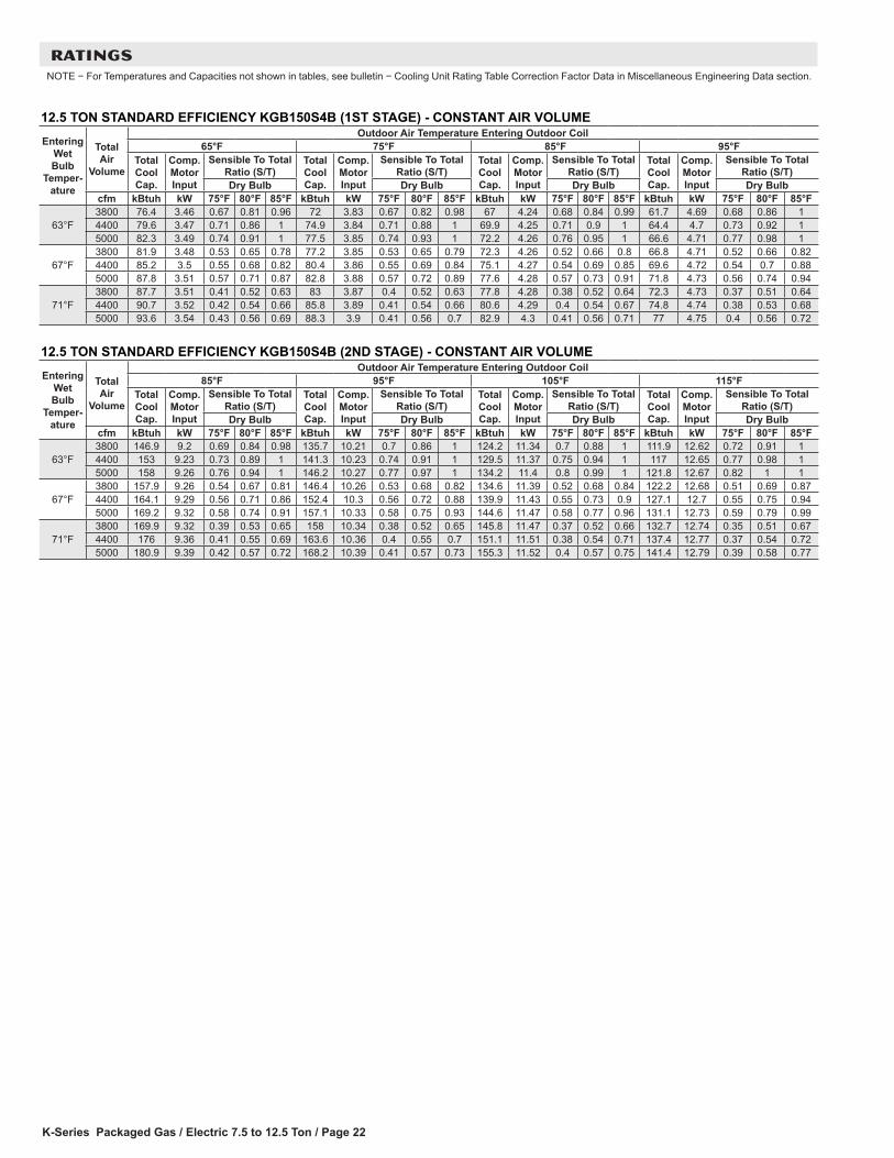
RATINGSNOTE − For Temperatures and Capacities not shown in tables, see bulletin − Cooling Unit Rating Table Correction Factor Data in Miscellaneous Engineering Data section.
12.5 TON STANDARD EFFICIENCY KGB150S4B (1ST STAGE) - CONSTANT AIR VOLUMEEntering
Wet Bulb
Temper-ature
Total Air
Volume
Outdoor Air Temperature Entering Outdoor Coil65°F 75°F 85°F 95°F
Total Cool Cap.
Comp. Motor Input
Sensible To Total Ratio (S/T)
Total Cool Cap.
Comp. Motor Input
Sensible To Total Ratio (S/T)
Total Cool Cap.
Comp. Motor Input
Sensible To Total Ratio (S/T)
Total Cool Cap.
Comp. Motor Input
Sensible To Total Ratio (S/T)
Dry Bulb Dry Bulb Dry Bulb Dry Bulbcfm kBtuh kW 75°F 80°F 85°F kBtuh kW 75°F 80°F 85°F kBtuh kW 75°F 80°F 85°F kBtuh kW 75°F 80°F 85°F
63°F3800 76.4 3.46 0.67 0.81 0.96 72 3.83 0.67 0.82 0.98 67 4.24 0.68 0.84 0.99 61.7 4.69 0.68 0.86 14400 79.6 3.47 0.71 0.86 1 74.9 3.84 0.71 0.88 1 69.9 4.25 0.71 0.9 1 64.4 4.7 0.73 0.92 15000 82.3 3.49 0.74 0.91 1 77.5 3.85 0.74 0.93 1 72.2 4.26 0.76 0.95 1 66.6 4.71 0.77 0.98 1
67°F3800 81.9 3.48 0.53 0.65 0.78 77.2 3.85 0.53 0.65 0.79 72.3 4.26 0.52 0.66 0.8 66.8 4.71 0.52 0.66 0.824400 85.2 3.5 0.55 0.68 0.82 80.4 3.86 0.55 0.69 0.84 75.1 4.27 0.54 0.69 0.85 69.6 4.72 0.54 0.7 0.885000 87.8 3.51 0.57 0.71 0.87 82.8 3.88 0.57 0.72 0.89 77.6 4.28 0.57 0.73 0.91 71.8 4.73 0.56 0.74 0.94
71°F3800 87.7 3.51 0.41 0.52 0.63 83 3.87 0.4 0.52 0.63 77.8 4.28 0.38 0.52 0.64 72.3 4.73 0.37 0.51 0.644400 90.7 3.52 0.42 0.54 0.66 85.8 3.89 0.41 0.54 0.66 80.6 4.29 0.4 0.54 0.67 74.8 4.74 0.38 0.53 0.685000 93.6 3.54 0.43 0.56 0.69 88.3 3.9 0.41 0.56 0.7 82.9 4.3 0.41 0.56 0.71 77 4.75 0.4 0.56 0.72
12.5 TON STANDARD EFFICIENCY KGB150S4B (2ND STAGE) - CONSTANT AIR VOLUMEEntering
Wet Bulb
Temper-ature
Total Air
Volume
Outdoor Air Temperature Entering Outdoor Coil85°F 95°F 105°F 115°F
Total Cool Cap.
Comp. Motor Input
Sensible To Total Ratio (S/T)
Total Cool Cap.
Comp. Motor Input
Sensible To Total Ratio (S/T)
Total Cool Cap.
Comp. Motor Input
Sensible To Total Ratio (S/T)
Total Cool Cap.
Comp. Motor Input
Sensible To Total Ratio (S/T)
Dry Bulb Dry Bulb Dry Bulb Dry Bulbcfm kBtuh kW 75°F 80°F 85°F kBtuh kW 75°F 80°F 85°F kBtuh kW 75°F 80°F 85°F kBtuh kW 75°F 80°F 85°F
63°F3800 146.9 9.2 0.69 0.84 0.98 135.7 10.21 0.7 0.86 1 124.2 11.34 0.7 0.88 1 111.9 12.62 0.72 0.91 14400 153 9.23 0.73 0.89 1 141.3 10.23 0.74 0.91 1 129.5 11.37 0.75 0.94 1 117 12.65 0.77 0.98 15000 158 9.26 0.76 0.94 1 146.2 10.27 0.77 0.97 1 134.2 11.4 0.8 0.99 1 121.8 12.67 0.82 1 1
67°F3800 157.9 9.26 0.54 0.67 0.81 146.4 10.26 0.53 0.68 0.82 134.6 11.39 0.52 0.68 0.84 122.2 12.68 0.51 0.69 0.874400 164.1 9.29 0.56 0.71 0.86 152.4 10.3 0.56 0.72 0.88 139.9 11.43 0.55 0.73 0.9 127.1 12.7 0.55 0.75 0.945000 169.2 9.32 0.58 0.74 0.91 157.1 10.33 0.58 0.75 0.93 144.6 11.47 0.58 0.77 0.96 131.1 12.73 0.59 0.79 0.99
71°F3800 169.9 9.32 0.39 0.53 0.65 158 10.34 0.38 0.52 0.65 145.8 11.47 0.37 0.52 0.66 132.7 12.74 0.35 0.51 0.674400 176 9.36 0.41 0.55 0.69 163.6 10.36 0.4 0.55 0.7 151.1 11.51 0.38 0.54 0.71 137.4 12.77 0.37 0.54 0.725000 180.9 9.39 0.42 0.57 0.72 168.2 10.39 0.41 0.57 0.73 155.3 11.52 0.4 0.57 0.75 141.4 12.79 0.39 0.58 0.77
K-Series Packaged Gas / Electric 7.5 to 12.5 Ton / Page 23
RATINGSNOTE − For Temperatures and Capacities not shown in tables, see bulletin − Cooling Unit Rating Table Correction Factor Data in Miscellaneous Engineering Data section.
7.5 TON HIGH EFFICIENCY KGA092H4M (1ST STAGE) - SINGLE ZONE VAV SUPPLY FAN SUPPLY AIR BLOWEREntering
Wet Bulb
Temper-ature
Total Air
Volume
Outdoor Air Temperature Entering Outdoor Coil65°F 75°F 85°F 95°F
Total Cool Cap.
Comp. Motor Input
Sensible To Total Ratio (S/T)
Total Cool Cap.
Comp. Motor Input
Sensible To Total Ratio (S/T)
Total Cool Cap.
Comp. Motor Input
Sensible To Total Ratio (S/T)
Total Cool Cap.
Comp. Motor Input
Sensible To Total Ratio (S/T)
Dry Bulb Dry Bulb Dry Bulb Dry Bulbcfm kBtuh kW 75°F 80°F 85°F kBtuh kW 75°F 80°F 85°F kBtuh kW 75°F 80°F 85°F kBtuh kW 75°F 80°F 85°F
63°F1680 43.6 1.94 0.59 0.69 0.81 41.9 2.20 0.59 0.70 0.82 40.0 2.49 0.59 0.71 0.84 38.0 2.81 0.59 0.72 0.862100 46.8 1.95 0.61 0.74 0.88 44.8 2.21 0.61 0.76 0.90 42.8 2.49 0.63 0.77 0.92 40.6 2.82 0.63 0.79 0.952520 49.1 1.96 0.65 0.80 0.96 47.0 2.21 0.66 0.81 0.98 44.8 2.50 0.67 0.83 1.00 42.5 2.82 0.68 0.86 1.00
67°F1680 46.5 1.95 0.48 0.56 0.65 44.7 2.21 0.48 0.56 0.66 42.8 2.49 0.47 0.57 0.67 40.7 2.82 0.48 0.57 0.682100 49.6 1.96 0.49 0.59 0.70 47.5 2.22 0.49 0.59 0.72 45.4 2.50 0.49 0.60 0.73 43.1 2.82 0.50 0.60 0.752520 52.0 1.97 0.51 0.62 0.76 49.9 2.22 0.52 0.63 0.77 47.6 2.50 0.51 0.64 0.79 45.1 2.82 0.52 0.65 0.82
71°F1680 49.4 1.96 0.38 0.46 0.54 47.5 2.22 0.38 0.46 0.54 45.5 2.50 0.38 0.46 0.55 43.4 2.82 0.37 0.46 0.552100 52.6 1.97 0.38 0.48 0.57 50.6 2.22 0.38 0.48 0.57 48.4 2.51 0.38 0.48 0.57 46.0 2.83 0.38 0.48 0.582520 54.9 1.98 0.39 0.49 0.59 52.6 2.23 0.39 0.50 0.60 50.3 2.51 0.39 0.50 0.61 47.8 2.83 0.39 0.50 0.63
7.5 TON HIGH EFFICIENCY KGA092H4M (2ND STAGE) - SINGLE ZONE VAV SUPPLY FAN SUPPLY AIR BLOWEREntering
Wet Bulb
Temper-ature
Total Air
Volume
Outdoor Air Temperature Entering Outdoor Coil85°F 95°F 105°F 115°F
Total Cool Cap.
Comp. Motor Input
Sensible To Total Ratio (S/T)
Total Cool Cap.
Comp. Motor Input
Sensible To Total Ratio (S/T)
Total Cool Cap.
Comp. Motor Input
Sensible To Total Ratio (S/T)
Total Cool Cap.
Comp. Motor Input
Sensible To Total Ratio (S/T)
Dry Bulb Dry Bulb Dry Bulb Dry Bulbcfm kBtuh kW 75°F 80°F 85°F kBtuh kW 75°F 80°F 85°F kBtuh kW 75°F 80°F 85°F kBtuh kW 75°F 80°F 85°F
63°F2400 87.9 4.98 0.68 0.83 0.99 83.4 5.62 0.69 0.85 1.00 78.4 6.36 0.71 0.88 1.00 73.1 7.23 0.73 0.92 1.003000 92.4 4.99 0.74 0.92 1.00 87.6 5.63 0.76 0.96 1.00 82.3 6.37 0.78 0.98 1.00 76.8 7.22 0.80 1.00 1.003600 96.0 5.00 0.80 1.00 1.00 91.2 5.64 0.82 1.00 1.00 86.4 6.37 0.85 1.00 1.00 81.2 7.22 0.88 1.00 1.00
67°F2400 93.3 4.99 0.54 0.66 0.79 88.4 5.63 0.54 0.67 0.81 83.3 6.37 0.55 0.68 0.84 78.0 7.23 0.56 0.71 0.883000 97.9 5.00 0.57 0.71 0.88 93.0 5.64 0.58 0.73 0.91 87.2 6.37 0.59 0.75 0.95 81.1 7.22 0.59 0.78 0.993600 101.4 5.01 0.61 0.77 0.97 95.6 5.64 0.61 0.79 1.00 90.0 6.38 0.62 0.82 1.00 83.6 7.22 0.64 0.86 1.00
71°F2400 99.1 5.00 0.41 0.52 0.64 94.0 5.64 0.41 0.53 0.65 88.6 6.37 0.40 0.54 0.66 82.7 7.22 0.41 0.55 0.683000 103.3 5.01 0.42 0.56 0.69 98.0 5.65 0.42 0.57 0.71 92.2 6.38 0.42 0.58 0.73 86.0 7.23 0.43 0.59 0.753600 106.9 5.02 0.44 0.60 0.75 101.2 5.66 0.43 0.60 0.77 95.0 6.38 0.44 0.61 0.80 88.3 7.22 0.44 0.63 0.84
7.5 TON STANDARD EFFICIENCY KGB092S4M (1ST STAGE) - SINGLE ZONE VAV SUPPLY FAN SUPPLY AIR BLOWEREntering
Wet Bulb
Temper-ature
Total Air
Volume
Outdoor Air Temperature Entering Outdoor Coil65°F 75°F 85°F 95°F
Total Cool Cap.
Comp. Motor Input
Sensible To Total Ratio (S/T)
Total Cool Cap.
Comp. Motor Input
Sensible To Total Ratio (S/T)
Total Cool Cap.
Comp. Motor Input
Sensible To Total Ratio (S/T)
Total Cool Cap.
Comp. Motor Input
Sensible To Total Ratio (S/T)
Dry Bulb Dry Bulb Dry Bulb Dry Bulbcfm kBtuh kW 75°F 80°F 85°F kBtuh kW 75°F 80°F 85°F kBtuh kW 75°F 80°F 85°F kBtuh kW 75°F 80°F 85°F
63°F1680 55.5 2.71 0.63 0.73 0.82 53.2 3.05 0.63 0.73 0.83 50.8 3.42 0.64 0.74 0.84 48.0 3.86 0.64 0.75 0.862100 59.7 2.75 0.66 0.76 0.87 57.2 3.08 0.66 0.77 0.88 54.3 3.45 0.66 0.78 0.9 51.3 3.88 0.67 0.8 0.922520 62.7 2.77 0.68 0.80 0.92 60.0 3.10 0.69 0.81 0.93 57.0 3.47 0.69 0.82 0.95 53.7 3.90 0.70 0.84 0.97
67°F1680 58.2 2.73 0.51 0.61 0.70 55.8 3.06 0.51 0.61 0.70 53.2 3.44 0.52 0.61 0.71 50.4 3.88 0.52 0.62 0.722100 62.5 2.77 0.53 0.63 0.73 59.9 3.09 0.54 0.64 0.74 57.1 3.47 0.54 0.64 0.75 53.9 3.90 0.54 0.65 0.762520 65.9 2.79 0.55 0.65 0.77 63.0 3.12 0.55 0.66 0.78 59.9 3.49 0.55 0.67 0.79 56.5 3.93 0.56 0.68 0.81
71°F1680 60.8 2.75 0.41 0.49 0.58 58.4 3.08 0.40 0.49 0.59 55.6 3.46 0.40 0.5 0.59 52.6 3.89 0.40 0.50 0.602100 65.3 2.79 0.42 0.52 0.61 62.6 3.11 0.42 0.52 0.61 59.6 3.49 0.42 0.52 0.62 56.3 3.92 0.41 0.53 0.632520 68.8 2.81 0.43 0.53 0.63 65.9 3.14 0.43 0.54 0.64 62.6 3.51 0.43 0.54 0.65 59.1 3.95 0.42 0.55 0.66
7.5 TON STANDARD EFFICIENCY KGB092S4M (2ND STAGE) - SINGLE ZONE VAV SUPPLY FAN SUPPLY AIR BLOWEREntering
Wet Bulb
Temper-ature
Total Air
Volume
Outdoor Air Temperature Entering Outdoor Coil85°F 95°F 105°F 115°F
Total Cool Cap.
Comp. Motor Input
Sensible To Total Ratio (S/T)
Total Cool Cap.
Comp. Motor Input
Sensible To Total Ratio (S/T)
Total Cool Cap.
Comp. Motor Input
Sensible To Total Ratio (S/T)
Total Cool Cap.
Comp. Motor Input
Sensible To Total Ratio (S/T)
Dry Bulb Dry Bulb Dry Bulb Dry Bulbcfm kBtuh kW 75°F 80°F 85°F kBtuh kW 75°F 80°F 85°F kBtuh kW 75°F 80°F 85°F kBtuh kW 75°F 80°F 85°F
63°F2400 86.0 5.76 0.68 0.82 0.96 80.6 6.50 0.69 0.84 0.98 74.8 7.36 0.71 0.87 1.00 68.6 8.33 0.73 0.90 1.003000 90.8 5.80 0.73 0.89 1.00 85.0 6.54 0.74 0.92 1.00 78.8 7.40 0.76 0.95 1.00 72.2 8.38 0.79 0.98 1.003600 94.4 5.82 0.77 0.95 1.00 88.3 6.57 0.79 0.98 1.00 82.0 7.43 0.82 0.99 1.00 75.5 8.42 0.85 1.00 1.00
67°F2400 90.7 5.79 0.54 0.66 0.78 85.2 6.54 0.54 0.67 0.80 79.3 7.40 0.55 0.69 0.83 72.7 8.38 0.56 0.70 0.863000 96.0 5.83 0.57 0.70 0.85 89.9 6.58 0.57 0.72 0.88 83.5 7.45 0.58 0.74 0.91 76.7 8.43 0.59 0.77 0.953600 99.7 5.85 0.59 0.75 0.92 93.4 6.61 0.60 0.77 0.95 86.6 7.48 0.61 0.79 0.98 79.3 8.47 0.63 0.83 1.00
71°F2400 95.0 5.82 0.41 0.53 0.64 89.5 6.58 0.41 0.53 0.65 83.3 7.44 0.4 0.54 0.66 76.7 8.43 0.40 0.55 0.683000 100.7 5.86 0.43 0.56 0.68 94.5 6.62 0.42 0.56 0.70 87.9 7.49 0.41 0.57 0.72 80.8 8.48 0.41 0.58 0.743600 104.7 5.89 0.43 0.58 0.72 98.1 6.65 0.43 0.59 0.74 91.2 7.52 0.43 0.60 0.77 83.8 8.52 0.43 0.62 0.80
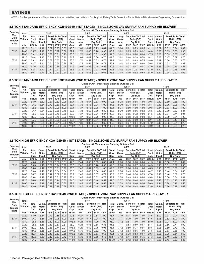
K-Series Packaged Gas / Electric 7.5 to 12.5 Ton / Page 24
RATINGSNOTE − For Temperatures and Capacities not shown in tables, see bulletin − Cooling Unit Rating Table Correction Factor Data in Miscellaneous Engineering Data section.
8.5 TON STANDARD EFFICIENCY KGB102S4M (1ST STAGE) - SINGLE ZONE VAV SUPPLY FAN SUPPLY AIR BLOWEREntering
Wet Bulb
Temper-ature
Total Air
Volume
Outdoor Air Temperature Entering Outdoor Coil65°F 75°F 85°F 95°F
Total Cool Cap.
Comp. Motor Input
Sensible To Total Ratio (S/T)
Total Cool Cap.
Comp. Motor Input
Sensible To Total Ratio (S/T)
Total Cool Cap.
Comp. Motor Input
Sensible To Total Ratio (S/T)
Total Cool Cap.
Comp. Motor Input
Sensible To Total Ratio (S/T)
Dry Bulb Dry Bulb Dry Bulb Dry Bulbcfm kBtuh kW 75°F 80°F 85°F kBtuh kW 75°F 80°F 85°F kBtuh kW 75°F 80°F 85°F kBtuh kW 75°F 80°F 85°F
63°F1920 51.1 2.42 0.62 0.73 0.83 48.0 2.69 0.62 0.73 0.84 44.6 3.00 0.61 0.73 0.85 41.1 3.37 0.61 0.74 0.872400 55.7 2.42 0.65 0.77 0.89 52.2 2.70 0.65 0.78 0.90 48.7 3.01 0.65 0.79 0.92 44.8 3.38 0.65 0.80 0.952880 59.1 2.43 0.68 0.81 0.95 55.5 2.70 0.68 0.82 0.96 51.6 3.01 0.69 0.84 0.98 47.5 3.38 0.69 0.86 1.00
67°F1920 54.4 2.42 0.51 0.60 0.70 51.2 2.69 0.49 0.60 0.70 47.8 3.01 0.48 0.59 0.70 44.1 3.38 0.47 0.59 0.702400 59.1 2.43 0.52 0.63 0.74 55.6 2.70 0.52 0.63 0.75 51.9 3.01 0.51 0.63 0.75 48.0 3.39 0.50 0.63 0.762880 62.7 2.43 0.54 0.66 0.78 59.0 2.71 0.54 0.66 0.79 55.1 3.02 0.53 0.67 0.80 50.8 3.39 0.53 0.67 0.82
71°F1920 57.6 2.42 0.40 0.49 0.58 54.2 2.69 0.38 0.48 0.58 50.8 3.01 0.37 0.47 0.57 47.0 3.38 0.35 0.46 0.572400 62.4 2.43 0.41 0.51 0.61 58.9 2.71 0.40 0.51 0.61 55.1 3.02 0.38 0.5 0.61 51.0 3.40 0.37 0.49 0.612880 66.1 2.44 0.42 0.53 0.64 62.3 2.72 0.41 0.53 0.64 58.3 3.03 0.40 0.52 0.65 54.0 3.41 0.38 0.52 0.65
8.5 TON STANDARD EFFICIENCY KGB102S4M (2ND STAGE) - SINGLE ZONE VAV SUPPLY FAN SUPPLY AIR BLOWEREntering
Wet Bulb
Temper-ature
Total Air
Volume
Outdoor Air Temperature Entering Outdoor Coil85°F 95°F 105°F 115°F
Total Cool Cap.
Comp. Motor Input
Sensible To Total Ratio (S/T)
Total Cool Cap.
Comp. Motor Input
Sensible To Total Ratio (S/T)
Total Cool Cap.
Comp. Motor Input
Sensible To Total Ratio (S/T)
Total Cool Cap.
Comp. Motor Input
Sensible To Total Ratio (S/T)
Dry Bulb Dry Bulb Dry Bulb Dry Bulbcfm kBtuh kW 75°F 80°F 85°F kBtuh kW 75°F 80°F 85°F kBtuh kW 75°F 80°F 85°F kBtuh kW 75°F 80°F 85°F
63°F2720 95.0 6.52 0.67 0.82 0.96 87.4 7.34 0.67 0.83 0.99 79.3 8.28 0.68 0.85 1.00 70.8 9.42 0.69 0.88 1.003400 101.3 6.54 0.72 0.89 1.00 93.1 7.35 0.73 0.91 1.00 84.6 8.30 0.74 0.94 1.00 75.4 9.43 0.76 0.98 1.004080 105.8 6.55 0.77 0.96 1.00 97.1 7.37 0.78 0.98 1.00 88.4 8.31 0.80 1.00 1.00 79.8 9.44 0.83 1.00 1.00
67°F2720 101.4 6.54 0.52 0.65 0.78 93.5 7.34 0.52 0.66 0.80 85.3 8.30 0.50 0.66 0.82 76.5 9.43 0.50 0.67 0.843400 108.0 6.56 0.55 0.70 0.85 99.6 7.37 0.55 0.71 0.87 90.8 8.31 0.55 0.72 0.90 81.5 9.43 0.54 0.74 0.944080 112.7 6.57 0.58 0.75 0.92 103.9 7.37 0.58 0.76 0.95 94.8 8.33 0.58 0.78 0.98 85.1 9.46 0.59 0.81 1.00
71°F2720 107.3 6.56 0.38 0.52 0.63 99.5 7.37 0.37 0.51 0.64 91.0 8.31 0.35 0.50 0.64 82.1 9.45 0.33 0.49 0.653400 114.3 6.58 0.40 0.54 0.68 105.7 7.39 0.39 0.54 0.69 96.6 8.34 0.37 0.54 0.70 87.2 9.46 0.35 0.54 0.724080 119.3 6.60 0.41 0.58 0.73 110.2 7.40 0.4 0.58 0.74 100.80 8.36 0.39 0.58 0.76 90.9 9.49 0.38 0.59 0.78
8.5 TON HIGH EFFICIENCY KGA102H4M (1ST STAGE) - SINGLE ZONE VAV SUPPLY FAN SUPPLY AIR BLOWEREntering
Wet Bulb
Temper-ature
Total Air
Volume
Outdoor Air Temperature Entering Outdoor Coil65°F 75°F 85°F 95°F
Total Cool Cap.
Comp. Motor Input
Sensible To Total Ratio (S/T)
Total Cool Cap.
Comp. Motor Input
Sensible To Total Ratio (S/T)
Total Cool Cap.
Comp. Motor Input
Sensible To Total Ratio (S/T)
Total Cool Cap.
Comp. Motor Input
Sensible To Total Ratio (S/T)
Dry Bulb Dry Bulb Dry Bulb Dry Bulbcfm kBtuh kW 75°F 80°F 85°F kBtuh kW 75°F 80°F 85°F kBtuh kW 75°F 80°F 85°F kBtuh kW 75°F 80°F 85°F
63°F1920 49.6 2.15 0.56 0.68 0.81 47.0 2.44 0.56 0.69 0.83 44.4 2.76 0.56 0.70 0.84 41.5 3.12 0.56 0.71 0.872400 53.3 2.16 0.59 0.74 0.90 50.5 2.45 0.60 0.76 0.93 47.5 2.76 0.60 0.77 0.95 44.3 3.13 0.61 0.79 0.982880 55.8 2.17 0.63 0.81 0.99 53.0 2.45 0.64 0.83 1.00 49.8 2.77 0.66 0.85 1.00 46.5 3.13 0.67 0.88 1.00
67°F1920 53.0 2.16 0.46 0.54 0.64 50.5 2.45 0.45 0.54 0.65 47.7 2.76 0.45 0.54 0.65 44.7 3.13 0.44 0.54 0.662400 56.7 2.17 0.47 0.57 0.70 53.9 2.46 0.47 0.57 0.72 50.8 2.77 0.46 0.58 0.73 47.6 3.13 0.46 0.58 0.752880 59.4 2.18 0.49 0.61 0.77 56.4 2.46 0.49 0.62 0.78 53.2 2.78 0.49 0.63 0.80 49.8 3.14 0.50 0.64 0.84
71°F1920 56.6 2.17 0.36 0.44 0.52 54.0 2.46 0.35 0.44 0.52 51.0 2.77 0.34 0.44 0.52 48.0 3.13 0.33 0.43 0.532400 60.3 2.18 0.37 0.46 0.55 57.3 2.46 0.36 0.46 0.55 54.2 2.78 0.35 0.46 0.56 50.9 3.14 0.34 0.46 0.562880 63.0 2.19 0.38 0.48 0.58 59.7 2.47 0.37 0.48 0.59 56.5 2.79 0.36 0.48 0.60 53.0 3.14 0.36 0.48 0.62
8.5 TON HIGH EFFICIENCY KGA102H4M (2ND STAGE) - SINGLE ZONE VAV SUPPLY FAN SUPPLY AIR BLOWEREntering
Wet Bulb
Temper-ature
Total Air
Volume
Outdoor Air Temperature Entering Outdoor Coil85°F 95°F 105°F 115°F
Total Cool Cap.
Comp. Motor Input
Sensible To Total Ratio (S/T)
Total Cool Cap.
Comp. Motor Input
Sensible To Total Ratio (S/T)
Total Cool Cap.
Comp. Motor Input
Sensible To Total Ratio (S/T)
Total Cool Cap.
Comp. Motor Input
Sensible To Total Ratio (S/T)
Dry Bulb Dry Bulb Dry Bulb Dry Bulbcfm kBtuh kW 75°F 80°F 85°F kBtuh kW 75°F 80°F 85°F kBtuh kW 75°F 80°F 85°F kBtuh kW 75°F 80°F 85°F
63°F2720 98.9 5.54 0.70 0.85 1.00 92.5 6.27 0.71 0.87 1.00 85.7 7.10 0.71 0.90 1.00 78.6 8.09 0.73 0.94 1.003400 104.2 5.56 0.76 0.95 1.00 97.5 6.27 0.77 0.98 1.00 90.4 7.11 0.79 1.00 1.00 83.6 8.08 0.82 1.00 1.004080 108.6 5.56 0.82 1.00 1.00 102.3 6.28 0.84 1.00 1.00 95.9 7.12 0.87 1.00 1.00 88.9 8.08 0.91 1.00 1.00
67°F2720 105.6 5.56 0.53 0.67 0.81 98.9 6.28 0.53 0.68 0.83 91.8 7.11 0.54 0.69 0.87 84.4 8.08 0.55 0.71 0.903400 110.9 5.57 0.58 0.74 0.91 103.8 6.29 0.59 0.75 0.94 96.4 7.12 0.59 0.77 0.97 88.5 8.08 0.59 0.79 1.004080 114.8 5.58 0.61 0.80 0.99 107.2 6.30 0.62 0.82 1.00 99.6 7.12 0.63 0.85 1.00 91.5 8.08 0.63 0.88 1.00
71°F2720 112.1 5.57 0.40 0.53 0.65 105.2 6.29 0.39 0.53 0.66 98.1 7.12 0.38 0.53 0.67 90.3 8.08 0.38 0.54 0.693400 117.6 5.59 0.42 0.57 0.72 110.4 6.30 0.41 0.58 0.73 102.7 7.12 0.41 0.58 0.75 94.3 8.08 0.40 0.59 0.774080 121.7 5.60 0.44 0.61 0.77 113.9 6.31 0.43 0.61 0.79 105.9 7.13 0.42 0.62 0.83 97.4 8.08 0.43 0.63 0.86
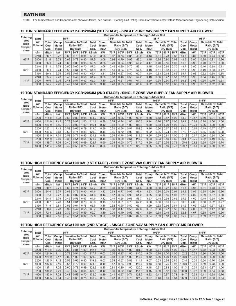
K-Series Packaged Gas / Electric 7.5 to 12.5 Ton / Page 25
RATINGSNOTE − For Temperatures and Capacities not shown in tables, see bulletin − Cooling Unit Rating Table Correction Factor Data in Miscellaneous Engineering Data section.
10 TON STANDARD EFFICIENCY KGB120S4M (1ST STAGE) - SINGLE ZONE VAV SUPPLY FAN SUPPLY AIR BLOWEREntering
Wet Bulb
Temper-ature
Total Air
Volume
Outdoor Air Temperature Entering Outdoor Coil65°F 75°F 85°F 95°F
Total Cool Cap.
Comp. Motor Input
Sensible To Total Ratio (S/T)
Total Cool Cap.
Comp. Motor Input
Sensible To Total Ratio (S/T)
Total Cool Cap.
Comp. Motor Input
Sensible To Total Ratio (S/T)
Total Cool Cap.
Comp. Motor Input
Sensible To Total Ratio (S/T)
Dry Bulb Dry Bulb Dry Bulb Dry Bulbcfm kBtuh kW 75°F 80°F 85°F kBtuh kW 75°F 80°F 85°F kBtuh kW 75°F 80°F 85°F kBtuh kW 75°F 80°F 85°F
63°F2240 56.7 2.72 0.62 0.73 0.84 53.0 3.05 0.62 0.73 0.85 49.0 3.43 0.61 0.73 0.86 44.7 3.87 0.60 0.74 0.882800 61.6 2.73 0.66 0.78 0.90 57.5 3.06 0.66 0.79 0.92 53.2 3.45 0.65 0.80 0.93 48.5 3.90 0.65 0.81 0.963360 65.1 2.74 0.69 0.83 0.96 60.8 3.08 0.70 0.84 0.98 56.2 3.47 0.70 0.85 1.00 51.5 3.92 0.70 0.87 1.00
67°F2240 61.1 2.73 0.50 0.60 0.70 57.2 3.06 0.49 0.60 0.70 53.1 3.45 0.48 0.59 0.70 48.7 3.90 0.46 0.58 0.712800 66.1 2.74 0.53 0.64 0.75 61.9 3.09 0.51 0.64 0.75 57.5 3.48 0.51 0.63 0.76 52.7 3.93 0.49 0.63 0.773360 69.8 2.75 0.55 0.67 0.80 65.4 3.11 0.54 0.67 0.80 60.7 3.50 0.53 0.68 0.82 55.7 3.95 0.52 0.68 0.84
71°F2240 65.5 2.73 0.40 0.49 0.58 61.4 3.08 0.38 0.48 0.58 57.2 3.48 0.36 0.47 0.57 52.7 3.93 0.34 0.45 0.562800 70.6 2.76 0.41 0.51 0.62 66.3 3.10 0.39 0.51 0.61 61.7 3.50 0.38 0.50 0.61 56.8 3.96 0.35 0.49 0.613360 74.5 2.76 0.42 0.54 0.65 69.8 3.12 0.40 0.53 0.65 65.0 3.52 0.39 0.52 0.66 59.9 3.98 0.37 0.52 0.66
10 TON STANDARD EFFICIENCY KGB120S4M (2ND STAGE) - SINGLE ZONE VAV SUPPLY FAN SUPPLY AIR BLOWEREntering
Wet Bulb
Temper-ature
Total Air
Volume
Outdoor Air Temperature Entering Outdoor Coil85°F 95°F 105°F 115°F
Total Cool Cap.
Comp. Motor Input
Sensible To Total Ratio (S/T)
Total Cool Cap.
Comp. Motor Input
Sensible To Total Ratio (S/T)
Total Cool Cap.
Comp. Motor Input
Sensible To Total Ratio (S/T)
Total Cool Cap.
Comp. Motor Input
Sensible To Total Ratio (S/T)
Dry Bulb Dry Bulb Dry Bulb Dry Bulbcfm kBtuh kW 75°F 80°F 85°F kBtuh kW 75°F 80°F 85°F kBtuh kW 75°F 80°F 85°F kBtuh kW 75°F 80°F 85°F
63°F3200 114.0 7.38 0.68 0.83 0.98 104.2 8.32 0.68 0.85 1.00 93.9 9.38 0.68 0.87 1.00 83.2 10.57 0.69 0.91 1.004000 121.0 7.42 0.73 0.92 1.00 111.1 8.38 0.74 0.94 1.00 100.5 9.44 0.76 0.97 1.00 89.4 10.64 0.78 1.00 1.004800 126.9 7.46 0.79 0.99 1.00 116.4 8.42 0.81 1.00 1.00 106.5 9.50 0.83 1.00 1.00 96.0 10.71 0.86 1.00 1.00
67°F3200 123.1 7.43 0.52 0.66 0.79 113.0 8.39 0.51 0.66 0.81 102.5 9.46 0.50 0.67 0.83 91.5 10.66 0.49 0.67 0.874000 130.6 7.48 0.55 0.71 0.88 120.0 8.44 0.55 0.72 0.90 108.8 9.52 0.55 0.74 0.93 97.0 10.73 0.55 0.76 0.984800 136.0 7.51 0.59 0.77 0.95 124.9 8.48 0.59 0.78 0.98 113.3 9.56 0.59 0.81 1.00 101.2 10.77 0.60 0.84 1.00
71°F3200 131.9 7.49 0.38 0.51 0.64 121.7 8.45 0.36 0.50 0.64 110.7 9.53 0.34 0.50 0.65 99.4 10.75 0.32 0.49 0.654000 139.7 7.54 0.40 0.55 0.69 128.7 8.50 0.39 0.55 0.70 117.5 9.60 0.37 0.55 0.72 105.4 10.82 0.35 0.55 0.744800 145.4 7.58 0.42 0.58 0.75 134.0 8.56 0.41 0.59 0.76 122.3 9.65 0.39 0.59 0.78 109.7 10.88 0.38 0.60 0.82
10 TON HIGH EFFICIENCY KGA120H4M (1ST STAGE) - SINGLE ZONE VAV SUPPLY FAN SUPPLY AIR BLOWEREntering
Wet Bulb
Temper-ature
Total Air
Volume
Outdoor Air Temperature Entering Outdoor Coil65°F 75°F 85°F 95°F
Total Cool Cap.
Comp. Motor Input
Sensible To Total Ratio (S/T)
Total Cool Cap.
Comp. Motor Input
Sensible To Total Ratio (S/T)
Total Cool Cap.
Comp. Motor Input
Sensible To Total Ratio (S/T)
Total Cool Cap.
Comp. Motor Input
Sensible To Total Ratio (S/T)
Dry Bulb Dry Bulb Dry Bulb Dry Bulbcfm kBtuh kW 75°F 80°F 85°F kBtuh kW 75°F 80°F 85°F kBtuh kW 75°F 80°F 85°F kBtuh kW 75°F 80°F 85°F
63°F2240 60.2 2.71 0.60 0.71 0.82 57.7 3.09 0.60 0.72 0.84 54.8 3.50 0.60 0.72 0.85 51.7 3.97 0.61 0.73 0.872800 64.6 2.75 0.63 0.76 0.90 61.6 3.12 0.63 0.77 0.92 58.6 3.53 0.64 0.79 0.94 55.3 3.99 0.65 0.80 0.963360 67.8 2.77 0.66 0.82 0.97 64.6 3.14 0.67 0.83 0.99 61.2 3.55 0.68 0.85 1.00 57.8 4.02 0.69 0.87 1.00
67°F2240 64.4 2.74 0.49 0.58 0.67 61.6 3.12 0.49 0.58 0.68 58.7 3.53 0.48 0.58 0.69 55.5 4.00 0.48 0.58 0.702800 68.7 2.78 0.51 0.61 0.73 65.6 3.15 0.51 0.61 0.73 62.2 3.56 0.50 0.61 0.75 58.8 4.03 0.50 0.62 0.773360 71.9 2.81 0.52 0.64 0.78 68.6 3.18 0.52 0.65 0.80 65.1 3.59 0.52 0.66 0.81 61.5 4.06 0.52 0.67 0.83
71°F2240 68.6 2.78 0.39 0.47 0.55 65.7 3.15 0.38 0.47 0.55 62.6 3.57 0.38 0.47 0.56 59.2 4.03 0.37 0.47 0.562800 72.9 2.82 0.39 0.49 0.59 69.7 3.19 0.39 0.49 0.59 66.4 3.60 0.38 0.49 0.59 62.8 4.07 0.38 0.49 0.603360 76.0 2.85 0.40 0.51 0.62 72.6 3.22 0.39 0.51 0.62 69.3 3.64 0.39 0.53 0.63 65.2 4.10 0.39 0.51 0.64
10 TON HIGH EFFICIENCY KGA120H4M (2ND STAGE) - SINGLE ZONE VAV SUPPLY FAN SUPPLY AIR BLOWEREntering
Wet Bulb
Temper-ature
Total Air
Volume
Outdoor Air Temperature Entering Outdoor Coil85°F 95°F 105°F 115°F
Total Cool Cap.
Comp. Motor Input
Sensible To Total Ratio (S/T)
Total Cool Cap.
Comp. Motor Input
Sensible To Total Ratio (S/T)
Total Cool Cap.
Comp. Motor Input
Sensible To Total Ratio (S/T)
Total Cool Cap.
Comp. Motor Input
Sensible To Total Ratio (S/T)
Dry Bulb Dry Bulb Dry Bulb Dry Bulbcfm kBtuh kW 75°F 80°F 85°F kBtuh kW 75°F 80°F 85°F kBtuh kW 75°F 80°F 85°F kBtuh kW 75°F 80°F 85°F
63°F3200 118.9 7.05 0.68 0.84 1.00 112.1 7.96 0.69 0.86 1.00 104.6 9.00 0.71 0.89 1.00 96.6 10.17 0.72 0.93 1.004000 124.9 7.11 0.74 0.94 1.00 117.7 8.03 0.76 0.97 1.00 110.0 9.05 0.78 1.00 1.00 102.2 10.23 0.80 1.00 1.004800 129.9 7.17 0.80 1.00 1.00 123.0 8.08 0.83 1.00 1.00 115.7 9.12 0.86 1.00 1.00 108.0 10.30 0.90 1.00 1.00
67°F3200 126.5 7.12 0.53 0.66 0.80 119.2 8.03 0.53 0.67 0.82 111.4 9.07 0.53 0.68 0.85 103.4 10.25 0.54 0.70 0.894000 132.6 7.19 0.57 0.72 0.90 124.8 8.10 0.57 0.73 0.93 116.7 9.13 0.58 0.75 0.97 108.0 10.30 0.59 0.78 1.004800 137.1 7.25 0.60 0.78 0.99 128.9 8.15 0.61 0.80 1.00 120.2 9.18 0.61 0.83 1.00 111.3 10.34 0.63 0.87 1.00
71°F3200 134.2 7.21 0.40 0.53 0.64 126.6 8.12 0.39 0.52 0.65 118.5 9.15 0.39 0.52 0.66 110.0 10.32 0.39 0.54 0.684000 140.0 7.28 0.41 0.56 0.70 132.0 8.19 0.41 0.57 0.71 123.5 9.22 0.41 0.57 0.73 114.7 10.38 0.41 0.58 0.764800 144.5 7.34 0.43 0.60 0.76 136.2 8.24 0.43 0.61 0.78 127.2 9.27 0.43 0.61 0.81 117.9 10.43 0.42 0.63 0.84
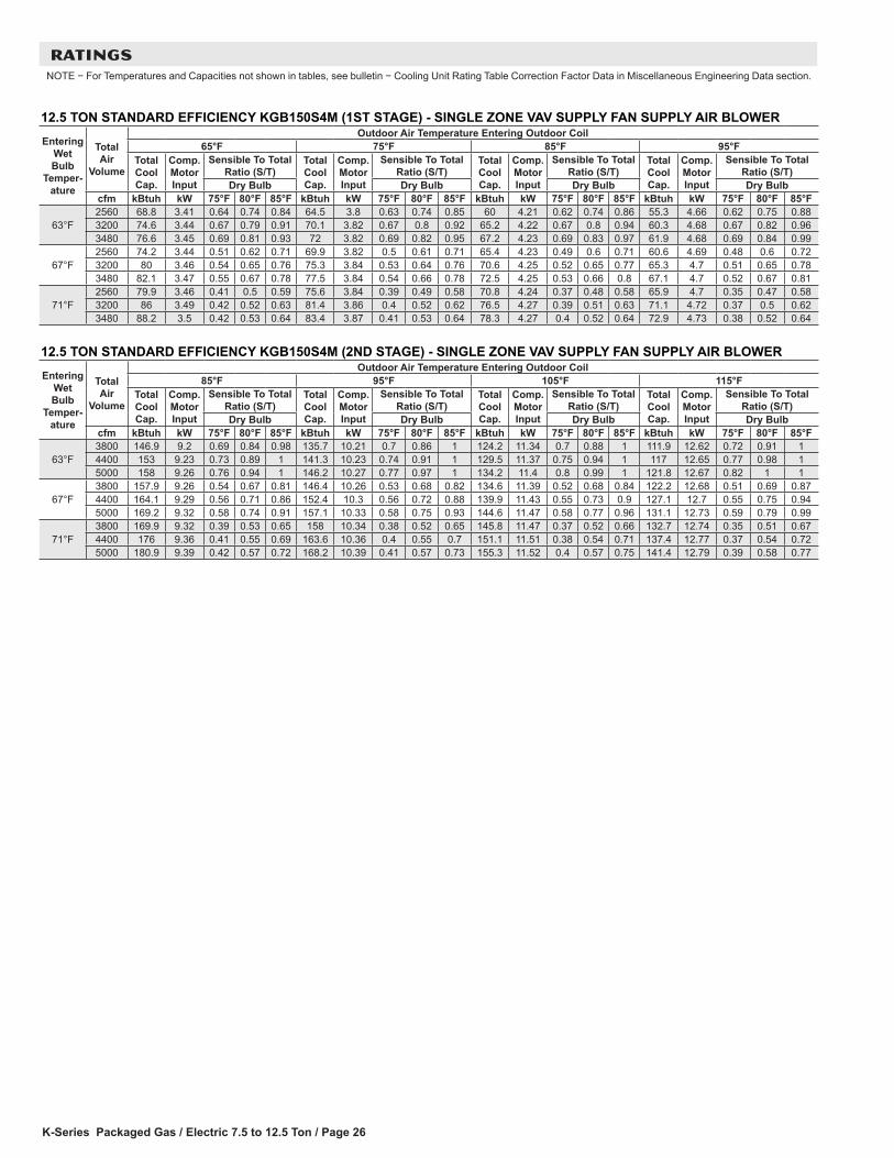
K-Series Packaged Gas / Electric 7.5 to 12.5 Ton / Page 26
RATINGSNOTE − For Temperatures and Capacities not shown in tables, see bulletin − Cooling Unit Rating Table Correction Factor Data in Miscellaneous Engineering Data section.
12.5 TON STANDARD EFFICIENCY KGB150S4M (1ST STAGE) - SINGLE ZONE VAV SUPPLY FAN SUPPLY AIR BLOWEREntering
Wet Bulb
Temper-ature
Total Air
Volume
Outdoor Air Temperature Entering Outdoor Coil65°F 75°F 85°F 95°F
Total Cool Cap.
Comp. Motor Input
Sensible To Total Ratio (S/T)
Total Cool Cap.
Comp. Motor Input
Sensible To Total Ratio (S/T)
Total Cool Cap.
Comp. Motor Input
Sensible To Total Ratio (S/T)
Total Cool Cap.
Comp. Motor Input
Sensible To Total Ratio (S/T)
Dry Bulb Dry Bulb Dry Bulb Dry Bulbcfm kBtuh kW 75°F 80°F 85°F kBtuh kW 75°F 80°F 85°F kBtuh kW 75°F 80°F 85°F kBtuh kW 75°F 80°F 85°F
63°F2560 68.8 3.41 0.64 0.74 0.84 64.5 3.8 0.63 0.74 0.85 60 4.21 0.62 0.74 0.86 55.3 4.66 0.62 0.75 0.883200 74.6 3.44 0.67 0.79 0.91 70.1 3.82 0.67 0.8 0.92 65.2 4.22 0.67 0.8 0.94 60.3 4.68 0.67 0.82 0.963480 76.6 3.45 0.69 0.81 0.93 72 3.82 0.69 0.82 0.95 67.2 4.23 0.69 0.83 0.97 61.9 4.68 0.69 0.84 0.99
67°F2560 74.2 3.44 0.51 0.62 0.71 69.9 3.82 0.5 0.61 0.71 65.4 4.23 0.49 0.6 0.71 60.6 4.69 0.48 0.6 0.723200 80 3.46 0.54 0.65 0.76 75.3 3.84 0.53 0.64 0.76 70.6 4.25 0.52 0.65 0.77 65.3 4.7 0.51 0.65 0.783480 82.1 3.47 0.55 0.67 0.78 77.5 3.84 0.54 0.66 0.78 72.5 4.25 0.53 0.66 0.8 67.1 4.7 0.52 0.67 0.81
71°F2560 79.9 3.46 0.41 0.5 0.59 75.6 3.84 0.39 0.49 0.58 70.8 4.24 0.37 0.48 0.58 65.9 4.7 0.35 0.47 0.583200 86 3.49 0.42 0.52 0.63 81.4 3.86 0.4 0.52 0.62 76.5 4.27 0.39 0.51 0.63 71.1 4.72 0.37 0.5 0.623480 88.2 3.5 0.42 0.53 0.64 83.4 3.87 0.41 0.53 0.64 78.3 4.27 0.4 0.52 0.64 72.9 4.73 0.38 0.52 0.64
12.5 TON STANDARD EFFICIENCY KGB150S4M (2ND STAGE) - SINGLE ZONE VAV SUPPLY FAN SUPPLY AIR BLOWEREntering
Wet Bulb
Temper-ature
Total Air
Volume
Outdoor Air Temperature Entering Outdoor Coil85°F 95°F 105°F 115°F
Total Cool Cap.
Comp. Motor Input
Sensible To Total Ratio (S/T)
Total Cool Cap.
Comp. Motor Input
Sensible To Total Ratio (S/T)
Total Cool Cap.
Comp. Motor Input
Sensible To Total Ratio (S/T)
Total Cool Cap.
Comp. Motor Input
Sensible To Total Ratio (S/T)
Dry Bulb Dry Bulb Dry Bulb Dry Bulbcfm kBtuh kW 75°F 80°F 85°F kBtuh kW 75°F 80°F 85°F kBtuh kW 75°F 80°F 85°F kBtuh kW 75°F 80°F 85°F
63°F3800 146.9 9.2 0.69 0.84 0.98 135.7 10.21 0.7 0.86 1 124.2 11.34 0.7 0.88 1 111.9 12.62 0.72 0.91 14400 153 9.23 0.73 0.89 1 141.3 10.23 0.74 0.91 1 129.5 11.37 0.75 0.94 1 117 12.65 0.77 0.98 15000 158 9.26 0.76 0.94 1 146.2 10.27 0.77 0.97 1 134.2 11.4 0.8 0.99 1 121.8 12.67 0.82 1 1
67°F3800 157.9 9.26 0.54 0.67 0.81 146.4 10.26 0.53 0.68 0.82 134.6 11.39 0.52 0.68 0.84 122.2 12.68 0.51 0.69 0.874400 164.1 9.29 0.56 0.71 0.86 152.4 10.3 0.56 0.72 0.88 139.9 11.43 0.55 0.73 0.9 127.1 12.7 0.55 0.75 0.945000 169.2 9.32 0.58 0.74 0.91 157.1 10.33 0.58 0.75 0.93 144.6 11.47 0.58 0.77 0.96 131.1 12.73 0.59 0.79 0.99
71°F3800 169.9 9.32 0.39 0.53 0.65 158 10.34 0.38 0.52 0.65 145.8 11.47 0.37 0.52 0.66 132.7 12.74 0.35 0.51 0.674400 176 9.36 0.41 0.55 0.69 163.6 10.36 0.4 0.55 0.7 151.1 11.51 0.38 0.54 0.71 137.4 12.77 0.37 0.54 0.725000 180.9 9.39 0.42 0.57 0.72 168.2 10.39 0.41 0.57 0.73 155.3 11.52 0.4 0.57 0.75 141.4 12.79 0.39 0.58 0.77
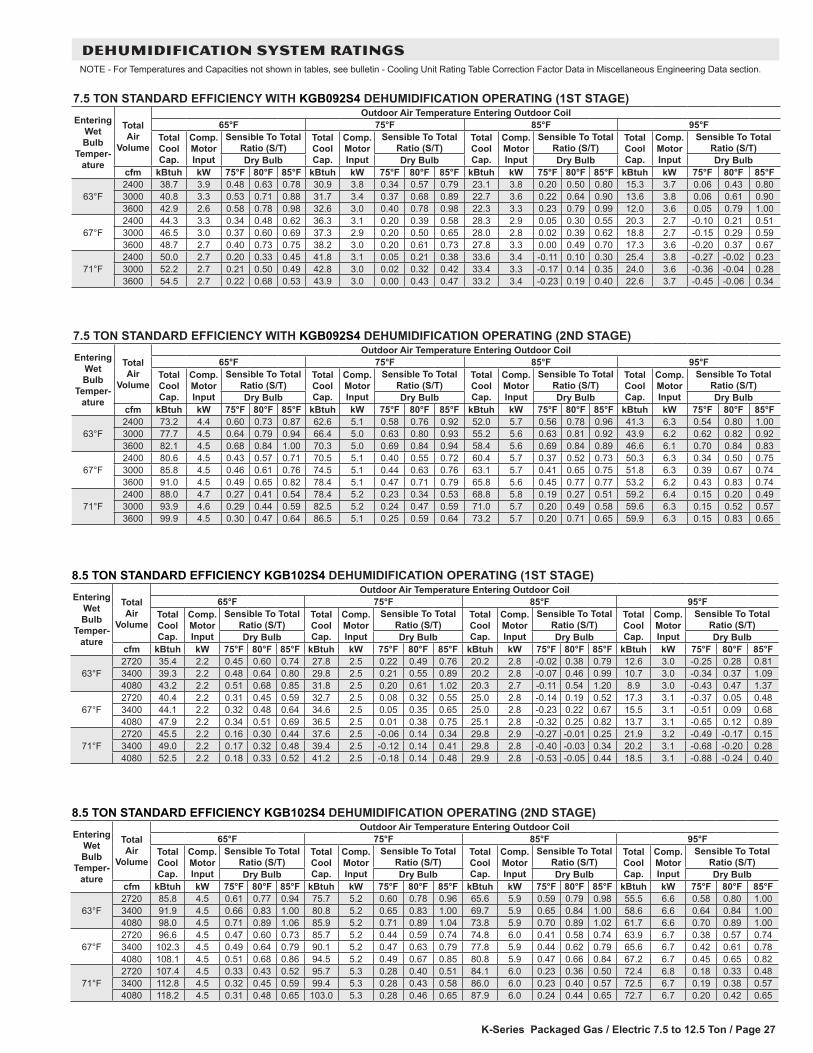
K-Series Packaged Gas / Electric 7.5 to 12.5 Ton / Page 27
7.5 TON STANDARD EFFICIENCY WITH KGB092S4 DEHUMIDIFICATION OPERATING (2ND STAGE)Entering
Wet Bulb
Temper-ature
Total Air
Volume
Outdoor Air Temperature Entering Outdoor Coil65°F 75°F 85°F 95°F
Total Cool Cap.
Comp. Motor Input
Sensible To Total Ratio (S/T)
Total Cool Cap.
Comp. Motor Input
Sensible To Total Ratio (S/T)
Total Cool Cap.
Comp. Motor Input
Sensible To Total Ratio (S/T)
Total Cool Cap.
Comp. Motor Input
Sensible To Total Ratio (S/T)
Dry Bulb Dry Bulb Dry Bulb Dry Bulbcfm kBtuh kW 75°F 80°F 85°F kBtuh kW 75°F 80°F 85°F kBtuh kW 75°F 80°F 85°F kBtuh kW 75°F 80°F 85°F
63°F2400 73.2 4.4 0.60 0.73 0.87 62.6 5.1 0.58 0.76 0.92 52.0 5.7 0.56 0.78 0.96 41.3 6.3 0.54 0.80 1.003000 77.7 4.5 0.64 0.79 0.94 66.4 5.0 0.63 0.80 0.93 55.2 5.6 0.63 0.81 0.92 43.9 6.2 0.62 0.82 0.923600 82.1 4.5 0.68 0.84 1.00 70.3 5.0 0.69 0.84 0.94 58.4 5.6 0.69 0.84 0.89 46.6 6.1 0.70 0.84 0.83
67°F2400 80.6 4.5 0.43 0.57 0.71 70.5 5.1 0.40 0.55 0.72 60.4 5.7 0.37 0.52 0.73 50.3 6.3 0.34 0.50 0.753000 85.8 4.5 0.46 0.61 0.76 74.5 5.1 0.44 0.63 0.76 63.1 5.7 0.41 0.65 0.75 51.8 6.3 0.39 0.67 0.743600 91.0 4.5 0.49 0.65 0.82 78.4 5.1 0.47 0.71 0.79 65.8 5.6 0.45 0.77 0.77 53.2 6.2 0.43 0.83 0.74
71°F2400 88.0 4.7 0.27 0.41 0.54 78.4 5.2 0.23 0.34 0.53 68.8 5.8 0.19 0.27 0.51 59.2 6.4 0.15 0.20 0.493000 93.9 4.6 0.29 0.44 0.59 82.5 5.2 0.24 0.47 0.59 71.0 5.7 0.20 0.49 0.58 59.6 6.3 0.15 0.52 0.573600 99.9 4.5 0.30 0.47 0.64 86.5 5.1 0.25 0.59 0.64 73.2 5.7 0.20 0.71 0.65 59.9 6.3 0.15 0.83 0.65
7.5 TON STANDARD EFFICIENCY WITH KGB092S4 DEHUMIDIFICATION OPERATING (1ST STAGE)Entering
Wet Bulb
Temper-ature
Total Air
Volume
Outdoor Air Temperature Entering Outdoor Coil65°F 75°F 85°F 95°F
Total Cool Cap.
Comp. Motor Input
Sensible To Total Ratio (S/T)
Total Cool Cap.
Comp. Motor Input
Sensible To Total Ratio (S/T)
Total Cool Cap.
Comp. Motor Input
Sensible To Total Ratio (S/T)
Total Cool Cap.
Comp. Motor Input
Sensible To Total Ratio (S/T)
Dry Bulb Dry Bulb Dry Bulb Dry Bulbcfm kBtuh kW 75°F 80°F 85°F kBtuh kW 75°F 80°F 85°F kBtuh kW 75°F 80°F 85°F kBtuh kW 75°F 80°F 85°F
63°F2400 38.7 3.9 0.48 0.63 0.78 30.9 3.8 0.34 0.57 0.79 23.1 3.8 0.20 0.50 0.80 15.3 3.7 0.06 0.43 0.803000 40.8 3.3 0.53 0.71 0.88 31.7 3.4 0.37 0.68 0.89 22.7 3.6 0.22 0.64 0.90 13.6 3.8 0.06 0.61 0.903600 42.9 2.6 0.58 0.78 0.98 32.6 3.0 0.40 0.78 0.98 22.3 3.3 0.23 0.79 0.99 12.0 3.6 0.05 0.79 1.00
67°F2400 44.3 3.3 0.34 0.48 0.62 36.3 3.1 0.20 0.39 0.58 28.3 2.9 0.05 0.30 0.55 20.3 2.7 -0.10 0.21 0.513000 46.5 3.0 0.37 0.60 0.69 37.3 2.9 0.20 0.50 0.65 28.0 2.8 0.02 0.39 0.62 18.8 2.7 -0.15 0.29 0.593600 48.7 2.7 0.40 0.73 0.75 38.2 3.0 0.20 0.61 0.73 27.8 3.3 0.00 0.49 0.70 17.3 3.6 -0.20 0.37 0.67
71°F2400 50.0 2.7 0.20 0.33 0.45 41.8 3.1 0.05 0.21 0.38 33.6 3.4 -0.11 0.10 0.30 25.4 3.8 -0.27 -0.02 0.233000 52.2 2.7 0.21 0.50 0.49 42.8 3.0 0.02 0.32 0.42 33.4 3.3 -0.17 0.14 0.35 24.0 3.6 -0.36 -0.04 0.283600 54.5 2.7 0.22 0.68 0.53 43.9 3.0 0.00 0.43 0.47 33.2 3.4 -0.23 0.19 0.40 22.6 3.7 -0.45 -0.06 0.34
DEHUMIDIFICATION SYSTEM RATINGSNOTE - For Temperatures and Capacities not shown in tables, see bulletin - Cooling Unit Rating Table Correction Factor Data in Miscellaneous Engineering Data section.
8.5 TON STANDARD EFFICIENCY KGB102S4 DEHUMIDIFICATION OPERATING (1ST STAGE)Entering
Wet Bulb
Temper-ature
Total Air
Volume
Outdoor Air Temperature Entering Outdoor Coil65°F 75°F 85°F 95°F
Total Cool Cap.
Comp. Motor Input
Sensible To Total Ratio (S/T)
Total Cool Cap.
Comp. Motor Input
Sensible To Total Ratio (S/T)
Total Cool Cap.
Comp. Motor Input
Sensible To Total Ratio (S/T)
Total Cool Cap.
Comp. Motor Input
Sensible To Total Ratio (S/T)
Dry Bulb Dry Bulb Dry Bulb Dry Bulbcfm kBtuh kW 75°F 80°F 85°F kBtuh kW 75°F 80°F 85°F kBtuh kW 75°F 80°F 85°F kBtuh kW 75°F 80°F 85°F
63°F2720 35.4 2.2 0.45 0.60 0.74 27.8 2.5 0.22 0.49 0.76 20.2 2.8 -0.02 0.38 0.79 12.6 3.0 -0.25 0.28 0.813400 39.3 2.2 0.48 0.64 0.80 29.8 2.5 0.21 0.55 0.89 20.2 2.8 -0.07 0.46 0.99 10.7 3.0 -0.34 0.37 1.094080 43.2 2.2 0.51 0.68 0.85 31.8 2.5 0.20 0.61 1.02 20.3 2.7 -0.11 0.54 1.20 8.9 3.0 -0.43 0.47 1.37
67°F2720 40.4 2.2 0.31 0.45 0.59 32.7 2.5 0.08 0.32 0.55 25.0 2.8 -0.14 0.19 0.52 17.3 3.1 -0.37 0.05 0.483400 44.1 2.2 0.32 0.48 0.64 34.6 2.5 0.05 0.35 0.65 25.0 2.8 -0.23 0.22 0.67 15.5 3.1 -0.51 0.09 0.684080 47.9 2.2 0.34 0.51 0.69 36.5 2.5 0.01 0.38 0.75 25.1 2.8 -0.32 0.25 0.82 13.7 3.1 -0.65 0.12 0.89
71°F2720 45.5 2.2 0.16 0.30 0.44 37.6 2.5 -0.06 0.14 0.34 29.8 2.9 -0.27 -0.01 0.25 21.9 3.2 -0.49 -0.17 0.153400 49.0 2.2 0.17 0.32 0.48 39.4 2.5 -0.12 0.14 0.41 29.8 2.8 -0.40 -0.03 0.34 20.2 3.1 -0.68 -0.20 0.284080 52.5 2.2 0.18 0.33 0.52 41.2 2.5 -0.18 0.14 0.48 29.9 2.8 -0.53 -0.05 0.44 18.5 3.1 -0.88 -0.24 0.40
8.5 TON STANDARD EFFICIENCY KGB102S4 DEHUMIDIFICATION OPERATING (2ND STAGE)Entering
Wet Bulb
Temper-ature
Total Air
Volume
Outdoor Air Temperature Entering Outdoor Coil65°F 75°F 85°F 95°F
Total Cool Cap.
Comp. Motor Input
Sensible To Total Ratio (S/T)
Total Cool Cap.
Comp. Motor Input
Sensible To Total Ratio (S/T)
Total Cool Cap.
Comp. Motor Input
Sensible To Total Ratio (S/T)
Total Cool Cap.
Comp. Motor Input
Sensible To Total Ratio (S/T)
Dry Bulb Dry Bulb Dry Bulb Dry Bulbcfm kBtuh kW 75°F 80°F 85°F kBtuh kW 75°F 80°F 85°F kBtuh kW 75°F 80°F 85°F kBtuh kW 75°F 80°F 85°F
63°F2720 85.8 4.5 0.61 0.77 0.94 75.7 5.2 0.60 0.78 0.96 65.6 5.9 0.59 0.79 0.98 55.5 6.6 0.58 0.80 1.003400 91.9 4.5 0.66 0.83 1.00 80.8 5.2 0.65 0.83 1.00 69.7 5.9 0.65 0.84 1.00 58.6 6.6 0.64 0.84 1.004080 98.0 4.5 0.71 0.89 1.06 85.9 5.2 0.71 0.89 1.04 73.8 5.9 0.70 0.89 1.02 61.7 6.6 0.70 0.89 1.00
67°F2720 96.6 4.5 0.47 0.60 0.73 85.7 5.2 0.44 0.59 0.74 74.8 6.0 0.41 0.58 0.74 63.9 6.7 0.38 0.57 0.743400 102.3 4.5 0.49 0.64 0.79 90.1 5.2 0.47 0.63 0.79 77.8 5.9 0.44 0.62 0.79 65.6 6.7 0.42 0.61 0.784080 108.1 4.5 0.51 0.68 0.86 94.5 5.2 0.49 0.67 0.85 80.8 5.9 0.47 0.66 0.84 67.2 6.7 0.45 0.65 0.82
71°F2720 107.4 4.5 0.33 0.43 0.52 95.7 5.3 0.28 0.40 0.51 84.1 6.0 0.23 0.36 0.50 72.4 6.8 0.18 0.33 0.483400 112.8 4.5 0.32 0.45 0.59 99.4 5.3 0.28 0.43 0.58 86.0 6.0 0.23 0.40 0.57 72.5 6.7 0.19 0.38 0.574080 118.2 4.5 0.31 0.48 0.65 103.0 5.3 0.28 0.46 0.65 87.9 6.0 0.24 0.44 0.65 72.7 6.7 0.20 0.42 0.65
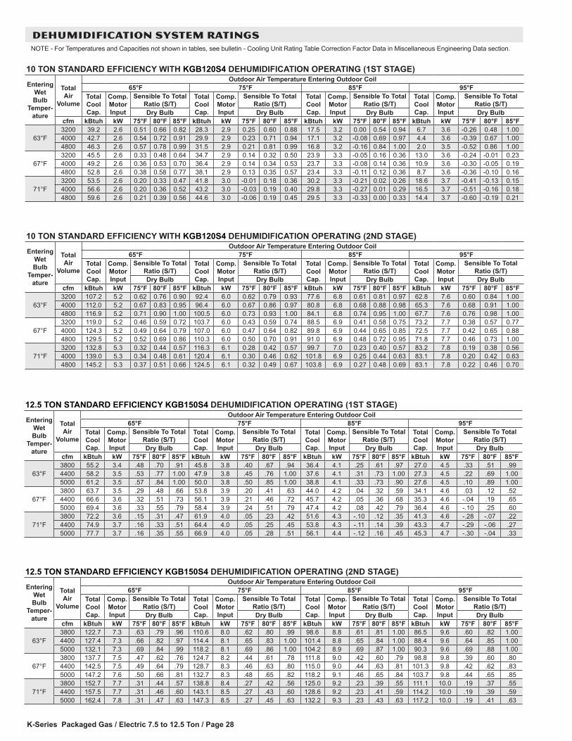
K-Series Packaged Gas / Electric 7.5 to 12.5 Ton / Page 28
10 TON STANDARD EFFICIENCY WITH KGB120S4 DEHUMIDIFICATION OPERATING (2ND STAGE)Entering
Wet Bulb
Temper-ature
Total Air
Volume
Outdoor Air Temperature Entering Outdoor Coil65°F 75°F 85°F 95°F
Total Cool Cap.
Comp. Motor Input
Sensible To Total Ratio (S/T)
Total Cool Cap.
Comp. Motor Input
Sensible To Total Ratio (S/T)
Total Cool Cap.
Comp. Motor Input
Sensible To Total Ratio (S/T)
Total Cool Cap.
Comp. Motor Input
Sensible To Total Ratio (S/T)
Dry Bulb Dry Bulb Dry Bulb Dry Bulbcfm kBtuh kW 75°F 80°F 85°F kBtuh kW 75°F 80°F 85°F kBtuh kW 75°F 80°F 85°F kBtuh kW 75°F 80°F 85°F
63°F3200 107.2 5.2 0.62 0.76 0.90 92.4 6.0 0.62 0.79 0.93 77.6 6.8 0.61 0.81 0.97 62.8 7.6 0.60 0.84 1.004000 112.0 5.2 0.67 0.83 0.95 96.4 6.0 0.67 0.86 0.97 80.8 6.8 0.68 0.88 0.98 65.3 7.6 0.68 0.91 1.004800 116.9 5.2 0.71 0.90 1.00 100.5 6.0 0.73 0.93 1.00 84.1 6.8 0.74 0.95 1.00 67.7 7.6 0.76 0.98 1.00
67°F3200 119.0 5.2 0.46 0.59 0.72 103.7 6.0 0.43 0.59 0.74 88.5 6.9 0.41 0.58 0.75 73.2 7.7 0.38 0.57 0.774000 124.3 5.2 0.49 0.64 0.79 107.0 6.0 0.47 0.64 0.82 89.8 6.9 0.44 0.65 0.85 72.5 7.7 0.42 0.65 0.884800 129.5 5.2 0.52 0.69 0.86 110.3 6.0 0.50 0.70 0.91 91.0 6.9 0.48 0.72 0.95 71.8 7.7 0.46 0.73 1.00
71°F3200 132.8 5.3 0.32 0.44 0.57 116.3 6.1 0.28 0.42 0.57 99.7 7.0 0.23 0.40 0.57 83.2 7.8 0.19 0.38 0.564000 139.0 5.3 0.34 0.48 0.61 120.4 6.1 0.30 0.46 0.62 101.8 6.9 0.25 0.44 0.63 83.1 7.8 0.20 0.42 0.634800 145.2 5.3 0.37 0.51 0.66 124.5 6.1 0.32 0.49 0.67 103.8 6.9 0.27 0.48 0.69 83.1 7.8 0.22 0.46 0.70
10 TON STANDARD EFFICIENCY WITH KGB120S4 DEHUMIDIFICATION OPERATING (1ST STAGE)Entering
Wet Bulb
Temper-ature
Total Air
Volume
Outdoor Air Temperature Entering Outdoor Coil65°F 75°F 85°F 95°F
Total Cool Cap.
Comp. Motor Input
Sensible To Total Ratio (S/T)
Total Cool Cap.
Comp. Motor Input
Sensible To Total Ratio (S/T)
Total Cool Cap.
Comp. Motor Input
Sensible To Total Ratio (S/T)
Total Cool Cap.
Comp. Motor Input
Sensible To Total Ratio (S/T)
Dry Bulb Dry Bulb Dry Bulb Dry Bulbcfm kBtuh kW 75°F 80°F 85°F kBtuh kW 75°F 80°F 85°F kBtuh kW 75°F 80°F 85°F kBtuh kW 75°F 80°F 85°F
63°F3200 39.2 2.6 0.51 0.66 0.82 28.3 2.9 0.25 0.60 0.88 17.5 3.2 0.00 0.54 0.94 6.7 3.6 -0.26 0.48 1.004000 42.7 2.6 0.54 0.72 0.91 29.9 2.9 0.23 0.71 0.94 17.1 3.2 -0.08 0.69 0.97 4.4 3.6 -0.39 0.67 1.004800 46.3 2.6 0.57 0.78 0.99 31.5 2.9 0.21 0.81 0.99 16.8 3.2 -0.16 0.84 1.00 2.0 3.5 -0.52 0.86 1.00
67°F3200 45.5 2.6 0.33 0.48 0.64 34.7 2.9 0.14 0.32 0.50 23.9 3.3 -0.05 0.16 0.36 13.0 3.6 -0.24 -0.01 0.234000 49.2 2.6 0.36 0.53 0.70 36.4 2.9 0.14 0.34 0.53 23.7 3.3 -0.08 0.14 0.36 10.9 3.6 -0.30 -0.05 0.194800 52.8 2.6 0.38 0.58 0.77 38.1 2.9 0.13 0.35 0.57 23.4 3.3 -0.11 0.12 0.36 8.7 3.6 -0.36 -0.10 0.16
71°F3200 53.5 2.6 0.20 0.33 0.47 41.8 3.0 -0.01 0.18 0.36 30.2 3.3 -0.21 0.02 0.26 18.6 3.7 -0.41 -0.13 0.154000 56.6 2.6 0.20 0.36 0.52 43.2 3.0 -0.03 0.19 0.40 29.8 3.3 -0.27 0.01 0.29 16.5 3.7 -0.51 -0.16 0.184800 59.6 2.6 0.21 0.39 0.56 44.6 3.0 -0.06 0.19 0.45 29.5 3.3 -0.33 0.00 0.33 14.4 3.7 -0.60 -0.19 0.21
DEHUMIDIFICATION SYSTEM RATINGSNOTE - For Temperatures and Capacities not shown in tables, see bulletin - Cooling Unit Rating Table Correction Factor Data in Miscellaneous Engineering Data section.
12.5 TON STANDARD EFFICIENCY KGB150S4 DEHUMIDIFICATION OPERATING (1ST STAGE)Entering
Wet Bulb
Temper-ature
Total Air
Volume
Outdoor Air Temperature Entering Outdoor Coil65°F 75°F 85°F 95°F
Total Cool Cap.
Comp. Motor Input
Sensible To Total Ratio (S/T)
Total Cool Cap.
Comp. Motor Input
Sensible To Total Ratio (S/T)
Total Cool Cap.
Comp. Motor Input
Sensible To Total Ratio (S/T)
Total Cool Cap.
Comp. Motor Input
Sensible To Total Ratio (S/T)
Dry Bulb Dry Bulb Dry Bulb Dry Bulbcfm kBtuh kW 75°F 80°F 85°F kBtuh kW 75°F 80°F 85°F kBtuh kW 75°F 80°F 85°F kBtuh kW 75°F 80°F 85°F
63°F3800 55.2 3.4 .48 .70 .91 45.8 3.8 .40 .67 .94 36.4 4.1 .25 .61 .97 27.0 4.5 .33 .51 .994400 58.2 3.5 .53 .77 1.00 47.9 3.8 .45 .76 1.00 37.6 4.1 .31 .73 1.00 27.3 4.5 .22 .69 1.005000 61.2 3.5 .57 .84 1.00 50.0 3.8 .50 .85 1.00 38.8 4.1 .33 .73 .90 27.6 4.5 .10 .89 1.00
67°F3800 63.7 3.5 .29 .48 .66 53.8 3.9 .20 .41 .63 44.0 4.2 .04 .32 .59 34.1 4.6 .03 .12 .524400 66.6 3.6 .32 .51 .73 56.1 3.9 .21 .46 .72 45.7 4.2 .05 .36 .68 35.3 4.6 -.04 .19 .655000 69.4 3.6 .33 .55 .79 58.4 3.9 .24 .51 .79 47.4 4.2 .08 .42 .79 36.4 4.6 -.10 .25 .60
71°F3800 72.2 3.6 .15 .31 .47 61.9 4.0 .05 .23 .42 51.6 4.3 -.10 .12 .35 41.3 4.6 -.28 -.07 .224400 74.9 3.7 .16 .33 .51 64.4 4.0 .05 .25 .45 53.8 4.3 -.11 .14 .39 43.3 4.7 -.29 -.06 .275000 77.7 3.7 .16 .35 .55 66.9 4.0 .05 .28 .51 56.1 4.4 -.12 .16 .45 45.3 4.7 -.30 -.04 .33
12.5 TON STANDARD EFFICIENCY KGB150S4 DEHUMIDIFICATION OPERATING (2ND STAGE)Entering
Wet Bulb
Temper-ature
Total Air
Volume
Outdoor Air Temperature Entering Outdoor Coil65°F 75°F 85°F 95°F
Total Cool Cap.
Comp. Motor Input
Sensible To Total Ratio (S/T)
Total Cool Cap.
Comp. Motor Input
Sensible To Total Ratio (S/T)
Total Cool Cap.
Comp. Motor Input
Sensible To Total Ratio (S/T)
Total Cool Cap.
Comp. Motor Input
Sensible To Total Ratio (S/T)
Dry Bulb Dry Bulb Dry Bulb Dry Bulbcfm kBtuh kW 75°F 80°F 85°F kBtuh kW 75°F 80°F 85°F kBtuh kW 75°F 80°F 85°F kBtuh kW 75°F 80°F 85°F
63°F3800 122.7 7.3 .63 .79 .96 110.6 8.0 .62 .80 .99 98.6 8.8 .61 .81 1.00 86.5 9.6 .60 .82 1.004400 127.4 7.3 .66 .82 .97 114.4 8.1 .65 .83 1.00 101.4 8.8 .65 .84 1.00 88.4 9.6 .64 .85 1.005000 132.1 7.3 .69 .84 .99 118.2 8.1 .69 .86 1.00 104.2 8.9 .69 .87 1.00 90.3 9.6 .69 .88 1.00
67°F3800 137.7 7.5 .47 .62 .76 124.7 8.2 .44 .61 .78 111.8 9.0 .42 .60 .79 98.8 9.8 .39 .60 .804400 142.5 7.5 .49 .64 .79 128.7 8.3 .46 .63 .80 115.0 9.0 .44 .63 .81 101.3 9.8 .42 .62 .835000 147.2 7.6 .50 .66 .81 132.7 8.3 .48 .65 .82 118.2 9.1 .46 .65 .84 103.7 9.8 .44 .65 .85
71°F3800 152.7 7.7 .31 .44 .57 138.8 8.4 .27 .42 .56 125.0 9.2 .23 .39 .55 111.1 10.0 .19 .37 .554400 157.5 7.7 .31 .46 .60 143.1 8.5 .27 .43 .60 128.6 9.2 .23 .41 .59 114.2 10.0 .19 .39 .595000 162.4 7.8 .31 .47 .63 147.3 8.5 .27 .45 .63 132.2 9.3 .23 .43 .63 117.2 10.0 .19 .41 .63
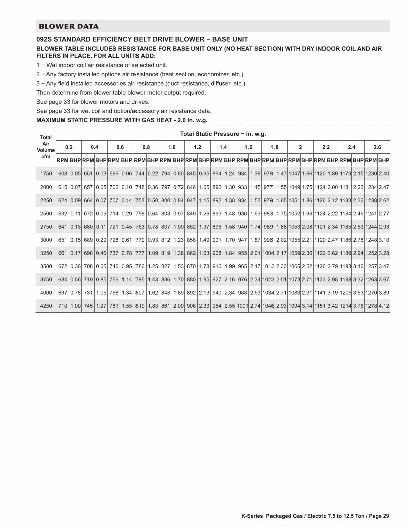
K-Series Packaged Gas / Electric 7.5 to 12.5 Ton / Page 29
BLOWER DATA
092S STANDARD EFFICIENCY BELT DRIVE BLOWER − BASE UNITBLOWER TABLE INCLUDES RESISTANCE FOR BASE UNIT ONLY (NO HEAT SECTION) WITH DRY INDOOR COIL AND AIR FILTERS IN PLACE. FOR ALL UNITS ADD:1 − Wet indoor coil air resistance of selected unit.2 − Any factory installed options air resistance (heat section, economizer, etc.)3 − Any field installed accessories air resistance (duct resistance, diffuser, etc.)Then determine from blower table blower motor output required.See page 33 for blower motors and drives.See page 33 for wet coil and option/accessory air resistance data.MAXIMUM STATIC PRESSURE WITH GAS HEAT - 2.0 in. w.g.
Total Air
Volume cfm
Total Static Pressure − in. w.g.
0.2 0.4 0.6 0.8 1.0 1.2 1.4 1.6 1.8 2 2.2 2.4 2.6
RPM BHP RPM BHP RPM BHP RPM BHP RPM BHP RPM BHP RPM BHP RPM BHP RPM BHP RPM BHP RPM BHP RPM BHP RPM BHP
1750 608 0.05 651 0.03 696 0.06 744 0.22 794 0.60 845 0.95 894 1.24 934 1.38 978 1.47 1047 1.66 1120 1.89 1179 2.15 1230 2.40
2000 615 0.07 657 0.05 702 0.10 748 0.36 797 0.72 846 1.05 892 1.30 933 1.45 977 1.55 1049 1.75 1124 2.00 1181 2.23 1234 2.47
2250 624 0.09 664 0.07 707 0.14 753 0.50 800 0.84 847 1.15 892 1.38 934 1.53 979 1.65 1051 1.86 1126 2.12 1183 2.36 1238 2.62
2500 632 0.11 672 0.09 714 0.29 758 0.64 803 0.97 849 1.26 893 1.48 936 1.63 983 1.75 1052 1.96 1124 2.22 1184 2.49 1241 2.77
2750 641 0.13 680 0.11 721 0.45 763 0.78 807 1.09 852 1.37 896 1.58 940 1.74 989 1.88 1053 2.08 1121 2.34 1185 2.63 1244 2.93
3000 651 0.15 689 0.29 728 0.61 770 0.93 812 1.23 856 1.49 901 1.70 947 1.87 996 2.02 1055 2.21 1120 2.47 1186 2.78 1248 3.10
3250 661 0.17 698 0.46 737 0.78 777 1.09 819 1.38 862 1.63 908 1.84 955 2.01 1004 2.17 1059 2.36 1122 2.62 1189 2.94 1252 3.28
3500 672 0.36 708 0.65 746 0.95 786 1.25 827 1.53 870 1.78 916 1.99 965 2.17 1013 2.33 1065 2.52 1126 2.79 1193 3.12 1257 3.47
3750 684 0.56 719 0.85 756 1.14 795 1.43 836 1.70 880 1.95 927 2.16 976 2.34 1023 2.51 1073 2.71 1133 2.98 1198 3.32 1263 3.67
4000 697 0.78 731 1.05 768 1.34 807 1.62 848 1.89 892 2.13 940 2.34 988 2.53 1034 2.71 1083 2.91 1141 3.19 1205 3.53 1270 3.89
4250 710 1.00 745 1.27 781 1.55 819 1.83 861 2.09 906 2.33 954 2.55 1001 2.74 1046 2.93 1094 3.14 1151 3.42 1214 3.76 1278 4.12
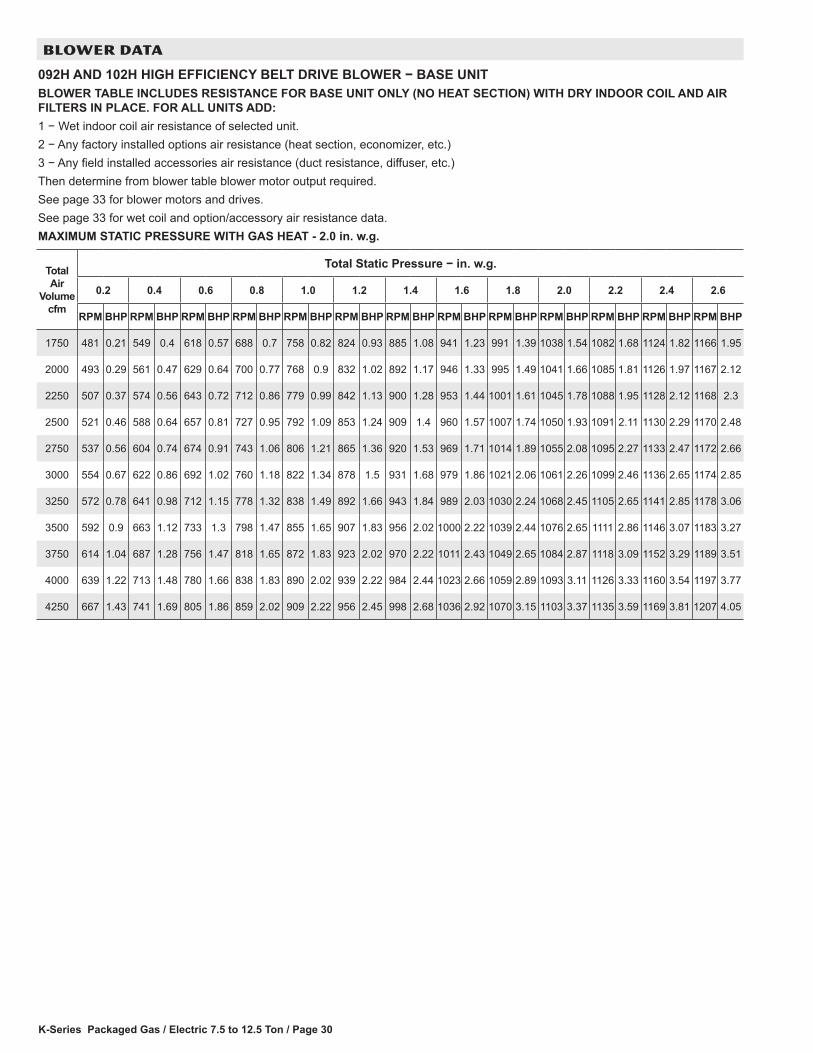
K-Series Packaged Gas / Electric 7.5 to 12.5 Ton / Page 30
BLOWER DATA
092H AND 102H HIGH EFFICIENCY BELT DRIVE BLOWER − BASE UNITBLOWER TABLE INCLUDES RESISTANCE FOR BASE UNIT ONLY (NO HEAT SECTION) WITH DRY INDOOR COIL AND AIR FILTERS IN PLACE. FOR ALL UNITS ADD:1 − Wet indoor coil air resistance of selected unit.2 − Any factory installed options air resistance (heat section, economizer, etc.)3 − Any field installed accessories air resistance (duct resistance, diffuser, etc.)Then determine from blower table blower motor output required.See page 33 for blower motors and drives. See page 33 for wet coil and option/accessory air resistance data.MAXIMUM STATIC PRESSURE WITH GAS HEAT - 2.0 in. w.g.
Total Air
Volume cfm
Total Static Pressure − in. w.g.
0.2 0.4 0.6 0.8 1.0 1.2 1.4 1.6 1.8 2.0 2.2 2.4 2.6
RPM BHP RPM BHP RPM BHP RPM BHP RPM BHP RPM BHP RPM BHP RPM BHP RPM BHP RPM BHP RPM BHP RPM BHP RPM BHP
1750 481 0.21 549 0.4 618 0.57 688 0.7 758 0.82 824 0.93 885 1.08 941 1.23 991 1.39 1038 1.54 1082 1.68 1124 1.82 1166 1.95
2000 493 0.29 561 0.47 629 0.64 700 0.77 768 0.9 832 1.02 892 1.17 946 1.33 995 1.49 1041 1.66 1085 1.81 1126 1.97 1167 2.12
2250 507 0.37 574 0.56 643 0.72 712 0.86 779 0.99 842 1.13 900 1.28 953 1.44 1001 1.61 1045 1.78 1088 1.95 1128 2.12 1168 2.3
2500 521 0.46 588 0.64 657 0.81 727 0.95 792 1.09 853 1.24 909 1.4 960 1.57 1007 1.74 1050 1.93 1091 2.11 1130 2.29 1170 2.48
2750 537 0.56 604 0.74 674 0.91 743 1.06 806 1.21 865 1.36 920 1.53 969 1.71 1014 1.89 1055 2.08 1095 2.27 1133 2.47 1172 2.66
3000 554 0.67 622 0.86 692 1.02 760 1.18 822 1.34 878 1.5 931 1.68 979 1.86 1021 2.06 1061 2.26 1099 2.46 1136 2.65 1174 2.85
3250 572 0.78 641 0.98 712 1.15 778 1.32 838 1.49 892 1.66 943 1.84 989 2.03 1030 2.24 1068 2.45 1105 2.65 1141 2.85 1178 3.06
3500 592 0.9 663 1.12 733 1.3 798 1.47 855 1.65 907 1.83 956 2.02 1000 2.22 1039 2.44 1076 2.65 1111 2.86 1146 3.07 1183 3.27
3750 614 1.04 687 1.28 756 1.47 818 1.65 872 1.83 923 2.02 970 2.22 1011 2.43 1049 2.65 1084 2.87 1118 3.09 1152 3.29 1189 3.51
4000 639 1.22 713 1.48 780 1.66 838 1.83 890 2.02 939 2.22 984 2.44 1023 2.66 1059 2.89 1093 3.11 1126 3.33 1160 3.54 1197 3.77
4250 667 1.43 741 1.69 805 1.86 859 2.02 909 2.22 956 2.45 998 2.68 1036 2.92 1070 3.15 1103 3.37 1135 3.59 1169 3.81 1207 4.05
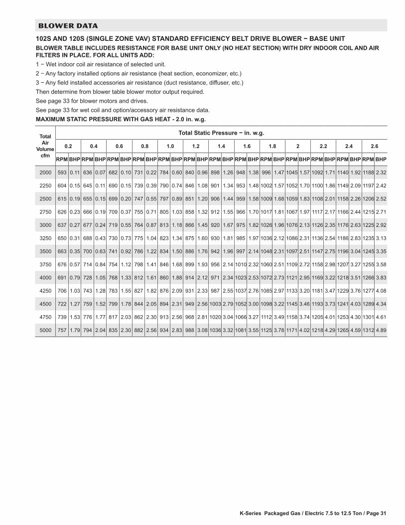
K-Series Packaged Gas / Electric 7.5 to 12.5 Ton / Page 31
BLOWER DATA
102S AND 120S (SINGLE ZONE VAV) STANDARD EFFICIENCY BELT DRIVE BLOWER − BASE UNITBLOWER TABLE INCLUDES RESISTANCE FOR BASE UNIT ONLY (NO HEAT SECTION) WITH DRY INDOOR COIL AND AIR FILTERS IN PLACE. FOR ALL UNITS ADD:1 − Wet indoor coil air resistance of selected unit.2 − Any factory installed options air resistance (heat section, economizer, etc.)3 − Any field installed accessories air resistance (duct resistance, diffuser, etc.)Then determine from blower table blower motor output required.See page 33 for blower motors and drives.See page 33 for wet coil and option/accessory air resistance data.MAXIMUM STATIC PRESSURE WITH GAS HEAT - 2.0 in. w.g.
Total Air
Volume cfm
Total Static Pressure − in. w.g.
0.2 0.4 0.6 0.8 1.0 1.2 1.4 1.6 1.8 2 2.2 2.4 2.6
RPM BHP RPM BHP RPM BHP RPM BHP RPM BHP RPM BHP RPM BHP RPM BHP RPM BHP RPM BHP RPM BHP RPM BHP RPM BHP
2000 593 0.11 636 0.07 682 0.10 731 0.22 784 0.60 840 0.96 898 1.26 948 1.38 996 1.47 1045 1.57 1092 1.71 1140 1.92 1188 2.32
2250 604 0.15 645 0.11 690 0.15 739 0.39 790 0.74 846 1.08 901 1.34 953 1.48 1002 1.57 1052 1.70 1100 1.86 1149 2.09 1197 2.42
2500 615 0.19 655 0.15 699 0.20 747 0.55 797 0.89 851 1.20 906 1.44 959 1.58 1009 1.68 1059 1.83 1108 2.01 1158 2.26 1206 2.52
2750 626 0.23 666 0.19 709 0.37 755 0.71 805 1.03 858 1.32 912 1.55 966 1.70 1017 1.81 1067 1.97 1117 2.17 1166 2.44 1215 2.71
3000 637 0.27 677 0.24 719 0.55 764 0.87 813 1.18 866 1.45 920 1.67 975 1.82 1026 1.96 1076 2.13 1126 2.35 1176 2.63 1225 2.92
3250 650 0.31 688 0.43 730 0.73 775 1.04 823 1.34 875 1.60 930 1.81 985 1.97 1036 2.12 1086 2.31 1136 2.54 1186 2.83 1235 3.13
3500 663 0.35 700 0.63 741 0.92 786 1.22 834 1.50 886 1.76 942 1.96 997 2.14 1048 2.31 1097 2.51 1147 2.75 1196 3.04 1245 3.35
3750 676 0.57 714 0.84 754 1.12 798 1.41 846 1.68 899 1.93 956 2.14 1010 2.32 1060 2.51 1109 2.72 1158 2.98 1207 3.27 1255 3.58
4000 691 0.79 728 1.05 768 1.33 812 1.61 860 1.88 914 2.12 971 2.34 1023 2.53 1072 2.73 1121 2.95 1169 3.22 1218 3.51 1266 3.83
4250 706 1.03 743 1.28 783 1.55 827 1.82 876 2.09 931 2.33 987 2.55 1037 2.76 1085 2.97 1133 3.20 1181 3.47 1229 3.76 1277 4.08
4500 722 1.27 759 1.52 799 1.78 844 2.05 894 2.31 949 2.56 1003 2.79 1052 3.00 1098 3.22 1145 3.46 1193 3.73 1241 4.03 1289 4.34
4750 739 1.53 776 1.77 817 2.03 862 2.30 913 2.56 968 2.81 1020 3.04 1066 3.27 1112 3.49 1158 3.74 1205 4.01 1253 4.30 1301 4.61
5000 757 1.79 794 2.04 835 2.30 882 2.56 934 2.83 988 3.08 1036 3.32 1081 3.55 1125 3.78 1171 4.02 1218 4.29 1265 4.59 1312 4.89
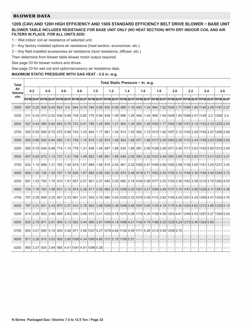
K-Series Packaged Gas / Electric 7.5 to 12.5 Ton / Page 32
BLOWER DATA
120S (CAV) AND 120H HIGH EFFICIENCY AND 150S STANDARD EFFICIENCY BELT DRIVE BLOWER − BASE UNITBLOWER TABLE INCLUDES RESISTANCE FOR BASE UNIT ONLY (NO HEAT SECTION) WITH DRY INDOOR COIL AND AIR FILTERS IN PLACE. FOR ALL UNITS ADD:1 − Wet indoor coil air resistance of selected unit.2 − Any factory installed options air resistance (heat section, economizer, etc.)3 − Any field installed accessories air resistance (duct resistance, diffuser, etc.)Then determine from blower table blower motor output required.See page 33 for blower motors and drives. See page 33 for wet coil and option/accessory air resistance data.MAXIMUM STATIC PRESSURE WITH GAS HEAT - 2.0 in. w.g.
Total Air
Volume cfm
Total Static Pressure − in. w.g.
0.2 0.4 0.6 0.8 1.0 1.2 1.4 1.6 1.8 2.0 2.2 2.4 2.6
RPM BHP RPM BHP RPM BHP RPM BHP RPM BHP RPM BHP RPM BHP RPM BHP RPM BHP RPM BHP RPM BHP RPM BHP RPM BHP
2000 497 0.25 558 0.44 624 0.6 694 0.74 764 0.85 830 0.99 889 1.16 943 1.34 994 1.52 1045 1.71 1096 1.89 1146 2.08 1197 2.27
2250 511 0.34 573 0.52 638 0.68 708 0.82 776 0.94 839 1.09 896 1.26 948 1.45 998 1.64 1048 1.83 1098 2.01 1149 2.2 1200 2.4
2500 527 0.44 589 0.62 654 0.78 723 0.91 789 1.05 850 1.21 904 1.39 955 1.58 1003 1.77 1052 1.96 1101 2.14 1152 2.33 1203 2.53
2750 545 0.55 606 0.72 672 0.88 740 1.03 804 1.17 861 1.34 914 1.53 962 1.72 1010 1.92 1057 2.10 1105 2.29 1154 2.47 1206 2.68
3000 564 0.66 626 0.84 692 1.01 759 1.16 819 1.32 874 1.49 924 1.68 971 1.88 1017 2.08 1063 2.26 1110 2.44 1158 2.63 1208 2.83
3250 585 0.79 648 0.98 714 1.14 778 1.31 836 1.48 887 1.66 935 1.86 981 2.06 1026 2.26 1071 2.45 1117 2.63 1163 2.80 1213 3.00
3500 607 0.93 672 1.13 737 1.31 798 1.48 852 1.66 901 1.85 948 2.05 993 2.26 1037 2.46 1081 2.65 1125 2.83 1171 3.01 1221 3.21
3750 632 1.10 698 1.31 762 1.50 819 1.67 869 1.86 915 2.05 961 2.25 1005 2.47 1049 2.68 1092 2.88 1136 3.05 1181 3.24 1231 3.45
4000 660 1.30 726 1.52 787 1.70 838 1.87 885 2.06 930 2.26 974 2.48 1018 2.71 1062 2.93 1105 3.12 1149 3.30 1194 3.49 1245 3.72
4250 691 1.53 755 1.75 810 1.91 857 2.07 901 2.27 945 2.50 990 2.74 1034 2.98 1077 3.20 1120 3.39 1163 3.58 1210 3.79 1262 4.03
4500 724 1.78 783 1.98 831 2.12 874 2.28 917 2.50 962 2.75 1006 3.02 1051 3.27 1094 3.49 1137 3.70 1181 3.89 1228 4.11 1281 4.38
4750 757 2.05 809 2.20 851 2.33 891 2.51 935 2.76 980 3.05 1025 3.33 1070 3.59 1113 3.82 1156 4.03 1201 4.24 1249 4.47 1303 4.75
5000 787 2.31 831 2.43 870 2.57 910 2.78 954 3.06 1000 3.38 1046 3.68 1091 3.95 1135 4.19 1178 4.40 1224 4.62 1272 4.86 1325 5.13
5250 814 2.55 852 2.66 889 2.83 930 3.09 975 3.41 1023 3.76 1070 4.08 1115 4.35 1159 4.59 1203 4.81 1248 5.03 1297 5.27 1350 5.53
5500 835 2.78 871 2.91 909 3.13 952 3.44 999 3.81 1049 4.18 1096 4.51 1142 4.79 1186 5.03 1229 5.24 1275 5.46 1324 5.69 - - - - - -
5750 854 3.01 890 3.19 930 3.48 977 3.86 1027 4.27 1078 4.66 1126 4.99 1171 5.26 1214 5.49 1258 5.70 - - - - - - - - - - - - - - - - - -
6000 871 3.26 910 3.53 955 3.90 1006 4.34 1060 4.80 1111 5.19 1158 5.51 - - - - - - - - - - - - - - - - - - - - - - - - - - - - - - - - - - - -
6250 890 3.57 934 3.94 985 4.41 1041 4.91 1096 5.38 - - - - - - - - - - - - - - - - - - - - - - - - - - - - - - - - - - - - - - - - - - - - - - - -
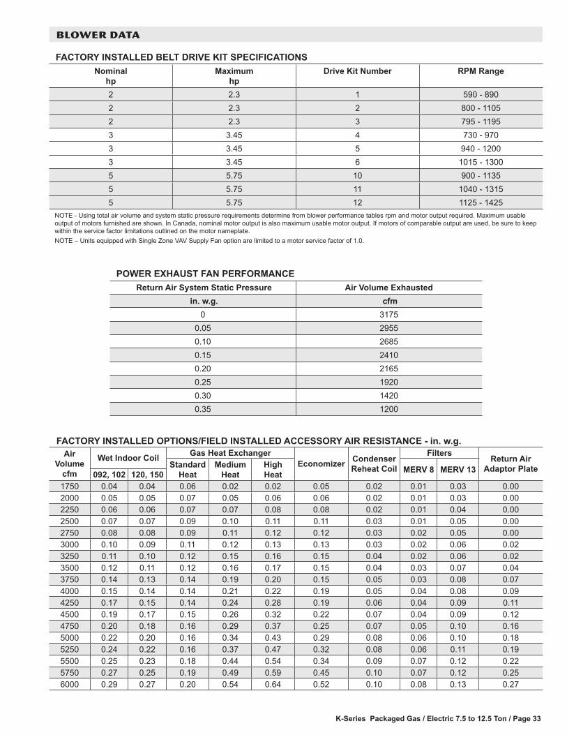
K-Series Packaged Gas / Electric 7.5 to 12.5 Ton / Page 33
BLOWER DATA
FACTORY INSTALLED BELT DRIVE KIT SPECIFICATIONSNominal
hpMaximum
hpDrive Kit Number RPM Range
2 2.3 1 590 - 8902 2.3 2 800 - 11052 2.3 3 795 - 11953 3.45 4 730 - 9703 3.45 5 940 - 12003 3.45 6 1015 - 13005 5.75 10 900 - 11355 5.75 11 1040 - 13155 5.75 12 1125 - 1425
NOTE - Using total air volume and system static pressure requirements determine from blower performance tables rpm and motor output required. Maximum usable output of motors furnished are shown. In Canada, nominal motor output is also maximum usable motor output. If motors of comparable output are used, be sure to keep within the service factor limitations outlined on the motor nameplate.NOTE – Units equipped with Single Zone VAV Supply Fan option are limited to a motor service factor of 1.0.
POWER EXHAUST FAN PERFORMANCE Return Air System Static Pressure Air Volume Exhausted
in. w.g. cfm 0 3175
0.05 29550.10 26850.15 24100.20 21650.25 19200.30 14200.35 1200
FACTORY INSTALLED OPTIONS/FIELD INSTALLED ACCESSORY AIR RESISTANCE - in. w.g.Air
Volume cfm
Wet Indoor Coil Gas Heat ExchangerEconomizer Condenser
Reheat Coil
Filters Return Air Adaptor PlateStandard
HeatMedium
HeatHigh Heat MERV 8 MERV 13092, 102 120, 150
1750 0.04 0.04 0.06 0.02 0.02 0.05 0.02 0.01 0.03 0.002000 0.05 0.05 0.07 0.05 0.06 0.06 0.02 0.01 0.03 0.002250 0.06 0.06 0.07 0.07 0.08 0.08 0.02 0.01 0.04 0.002500 0.07 0.07 0.09 0.10 0.11 0.11 0.03 0.01 0.05 0.002750 0.08 0.08 0.09 0.11 0.12 0.12 0.03 0.02 0.05 0.003000 0.10 0.09 0.11 0.12 0.13 0.13 0.03 0.02 0.06 0.023250 0.11 0.10 0.12 0.15 0.16 0.15 0.04 0.02 0.06 0.023500 0.12 0.11 0.12 0.16 0.17 0.15 0.04 0.03 0.07 0.043750 0.14 0.13 0.14 0.19 0.20 0.15 0.05 0.03 0.08 0.074000 0.15 0.14 0.14 0.21 0.22 0.19 0.05 0.04 0.08 0.094250 0.17 0.15 0.14 0.24 0.28 0.19 0.06 0.04 0.09 0.114500 0.19 0.17 0.15 0.26 0.32 0.22 0.07 0.04 0.09 0.124750 0.20 0.18 0.16 0.29 0.37 0.25 0.07 0.05 0.10 0.165000 0.22 0.20 0.16 0.34 0.43 0.29 0.08 0.06 0.10 0.185250 0.24 0.22 0.16 0.37 0.47 0.32 0.08 0.06 0.11 0.195500 0.25 0.23 0.18 0.44 0.54 0.34 0.09 0.07 0.12 0.225750 0.27 0.25 0.19 0.49 0.59 0.45 0.10 0.07 0.12 0.256000 0.29 0.27 0.20 0.54 0.64 0.52 0.10 0.08 0.13 0.27
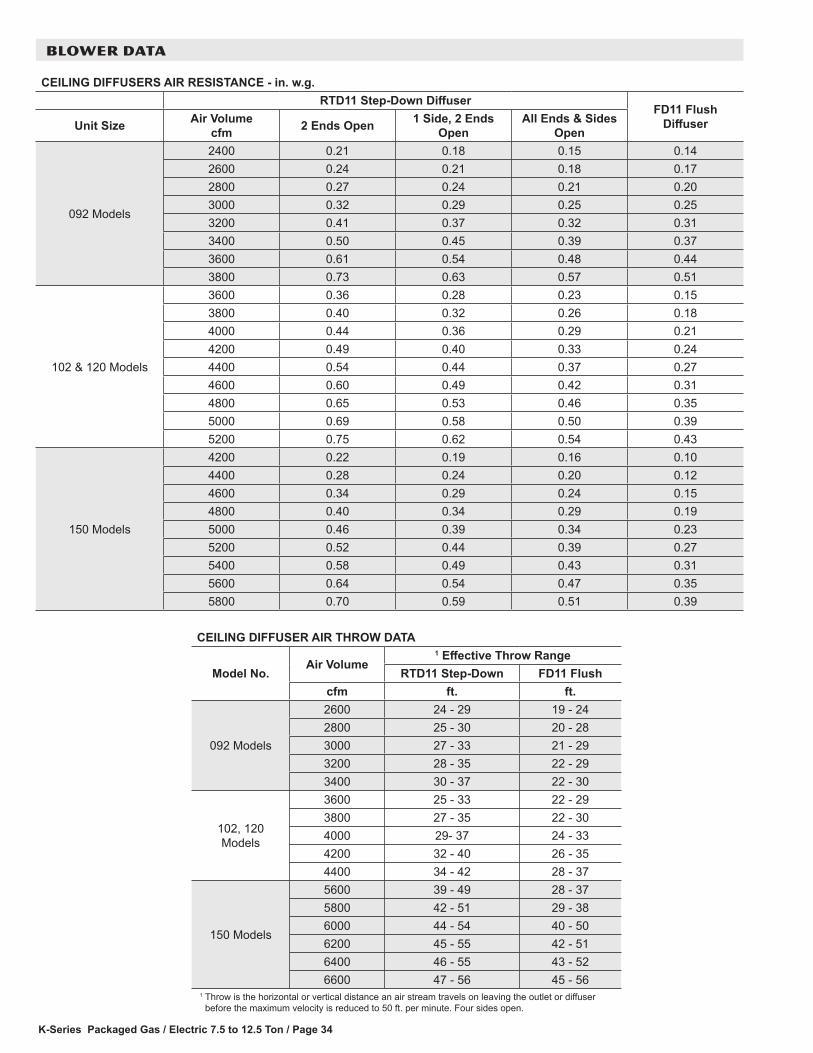
K-Series Packaged Gas / Electric 7.5 to 12.5 Ton / Page 34
BLOWER DATA
CEILING DIFFUSERS AIR RESISTANCE - in. w.g.RTD11 Step-Down Diffuser
FD11 Flush DiffuserUnit Size Air Volume
cfm 2 Ends Open 1 Side, 2 Ends Open
All Ends & Sides Open
092 Models
2400 0.21 0.18 0.15 0.142600 0.24 0.21 0.18 0.172800 0.27 0.24 0.21 0.203000 0.32 0.29 0.25 0.253200 0.41 0.37 0.32 0.313400 0.50 0.45 0.39 0.373600 0.61 0.54 0.48 0.443800 0.73 0.63 0.57 0.51
102 & 120 Models
3600 0.36 0.28 0.23 0.153800 0.40 0.32 0.26 0.184000 0.44 0.36 0.29 0.214200 0.49 0.40 0.33 0.244400 0.54 0.44 0.37 0.274600 0.60 0.49 0.42 0.314800 0.65 0.53 0.46 0.355000 0.69 0.58 0.50 0.395200 0.75 0.62 0.54 0.43
150 Models
4200 0.22 0.19 0.16 0.104400 0.28 0.24 0.20 0.124600 0.34 0.29 0.24 0.154800 0.40 0.34 0.29 0.195000 0.46 0.39 0.34 0.235200 0.52 0.44 0.39 0.275400 0.58 0.49 0.43 0.315600 0.64 0.54 0.47 0.355800 0.70 0.59 0.51 0.39
CEILING DIFFUSER AIR THROW DATA
Model No.Air Volume
1 Effective Throw RangeRTD11 Step-Down FD11 Flush
cfm ft. ft.
092 Models
2600 24 - 29 19 - 242800 25 - 30 20 - 283000 27 - 33 21 - 293200 28 - 35 22 - 293400 30 - 37 22 - 30
102, 120 Models
3600 25 - 33 22 - 293800 27 - 35 22 - 304000 29- 37 24 - 334200 32 - 40 26 - 354400 34 - 42 28 - 37
150 Models
5600 39 - 49 28 - 375800 42 - 51 29 - 386000 44 - 54 40 - 506200 45 - 55 42 - 516400 46 - 55 43 - 526600 47 - 56 45 - 56
1 Throw is the horizontal or vertical distance an air stream travels on leaving the outlet or diffuser before the maximum velocity is reduced to 50 ft. per minute. Four sides open.

K-Series Packaged Gas / Electric 7.5 to 12.5 Ton / Page 35
ELECTRICAL DATA 7.5 TON7.5 TON STANDARD EFFICIENCY (R-410A) KGB092S41 Voltage - 60hz 208/230V - 3 Ph 460V - 3 Ph 575V - 3 PhCompressor 1 Rated Load Amps 13.1 6.1 4.4
Locked Rotor Amps 83.1 41 33Compressor 2 Rated Load Amps 13.1 6.1 4.4
Locked Rotor Amps 83.1 41 33Outdoor Fan Motors (2)
Full Load Amps 2.4 1.3 1(total) (4.8) (2.6) (2)
Power Exhaust (1) 0.33 HP
Full Load Amps 2.4 1.3 1
Service Outlet 115V GFI (amps) 15 15 20Indoor Blower Motor
Horsepower 2 3 5 2 3 5 2 3 5Full Load Amps 7.5 10.6 16.7 3.4 4.8 7.6 2.7 3.9 6.1
2 Maximum Overcurrent Protection
Unit Only 50 50 60 25 25 30 15 20 20With (1) 0.33 HP
Power Exhaust50 60 70 25 25 30 20 20 25
3 Minimum Circuit Ampacity
Unit Only 42 45 52 20 22 25 15 16 19With (1) 0.33 HP
Power Exhaust45 48 55 22 23 26 16 17 20
ELECTRICAL ACCESSORIES
Disconnect 80 amp - C1DISC080B-1 54W56 (all models)NOTE - All units have a minimum Short Circuit Current Rating (SCCR) of 5000 amps.1 Extremes of operating range are plus and minus 10% of line voltage.2 HACR type breaker or fuse.3 Refer to National or Canadian Electrical Code manual to determine wire, fuse and disconnect size requirements.
7.5 TON HIGH EFFICIENCY (R-410A) KGA092H4
1 Voltage - 60hz 208/230V - 3 Ph 460V - 3 Ph 575V - 3 Ph
Compressor 1 Rated Load Amps 11.6 5.5 4.7
Locked Rotor Amps 86 37 34
Compressor 2 Rated Load Amps 11.6 5.5 4.7
Locked Rotor Amps 86 37 34
Outdoor Fan Motors (2)
Full Load Amps 2.4 1.3 1
(total) (4.8) (2.6) (2)
Power Exhaust (1) 0.33 HP
Full Load Amps 2.4 1.3 1
Service Outlet 115V GFI (amps) 15 15 20
Indoor Blower Motor
Horsepower 2 3 5 2 3 5 2 3 5
Full Load Amps 7.5 10.6 16.7 3.4 4.8 7.6 2.7 3.9 6.12 Maximum
Overcurrent Protection
Unit Only 45 50 60 20 25 30 20 20 25
With (1) 0.33 HP Power Exhaust
50 50 60 25 25 30 20 20 25
3 Minimum Circuit Ampacity
Unit Only 39 42 49 19 20 24 16 17 20
With (1) 0.33 HP Power Exhaust
41 44 52 20 22 25 17 18 21
ELECTRICAL ACCESSORIES
Disconnect 80 amp - C1DISC080B-1 54W56 (all models)NOTE - All units have a minimum Short Circuit Current Rating (SCCR) of 5000 amps.1 Extremes of operating range are plus and minus 10% of line voltage.2 HACR type breaker or fuse.3 Refer to National or Canadian Electrical Code manual to determine wire, fuse and disconnect size requirements.
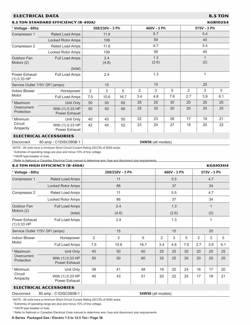
K-Series Packaged Gas / Electric 7.5 to 12.5 Ton / Page 36
ELECTRICAL DATA 8.5 TON8.5 TON STANDARD EFFICIENCY (R-410A) KGB102S41 Voltage - 60hz 208/230V - 3 Ph 460V - 3 Ph 575V - 3 PhCompressor 1 Rated Load Amps 11.9 6.7 5.4
Locked Rotor Amps 109 59 40
Compressor 2 Rated Load Amps 11.9 6.7 5.4
Locked Rotor Amps 109 59 40
Outdoor Fan Motors (2)
Full Load Amps 2.4 (4.8)
1.3 (2.6)
1 (2)
(total)Power Exhaust (1) 0.33 HP
Full Load Amps 2.4 1.3 1
Service Outlet 115V GFI (amps) 15 15 20
Indoor Blower Motor
Horsepower 2 3 5 2 3 5 2 3 5
Full Load Amps 7.5 10.6 16.7 3.4 4.8 7.6 2.7 3.9 6.12 Maximum
Overcurrent Protection
Unit Only 50 50 60 25 25 30 20 20 25
With (1) 0.33 HP Power Exhaust
50 50 60 25 30 30 20 20 25
3 Minimum Circuit Ampacity
Unit Only 40 43 50 22 23 26 17 19 21
With (1) 0.33 HP Power Exhaust
42 45 52 23 24 27 18 20 22
ELECTRICAL ACCESSORIES
Disconnect 80 amp - C1DISC080B-1 54W56 (all models)NOTE - All units have a minimum Short Circuit Current Rating (SCCR) of 5000 amps.1 Extremes of operating range are plus and minus 10% of line voltage.2 HACR type breaker or fuse.3 Refer to National or Canadian Electrical Code manual to determine wire, fuse and disconnect size requirements.
8.5 TON HIGH EFFICIENCY (R-410A) KGA102H4
1 Voltage - 60hz 208/230V - 3 Ph 460V - 3 Ph 575V - 3 Ph
Compressor 1 Rated Load Amps 11 5.5 4.7
Locked Rotor Amps 86 37 34
Compressor 2 Rated Load Amps 11 5.5 4.7
Locked Rotor Amps 86 37 34
Outdoor Fan Motors (2)
Full Load Amps 2.4 1.3 1
(total) (4.8) (2.6) (2)
Power Exhaust (1) 0.33 HP
Full Load Amps 2.4 1.3 1
Service Outlet 115V GFI (amps) 15 15 20
Indoor Blower Motor
Horsepower 2 3 5 2 3 5 2 3 5
Full Load Amps 7.5 10.6 16.7 3.4 4.8 7.6 2.7 3.9 6.12 Maximum
Overcurrent Protection
Unit Only 45 50 60 20 25 30 20 20 25
With (1) 0.33 HP Power Exhaust
50 50 60 25 25 30 20 20 25
3 Minimum Circuit Ampacity
Unit Only 38 41 48 19 20 24 16 17 20
With (1) 0.33 HP Power Exhaust
40 43 51 20 22 25 17 18 21
ELECTRICAL ACCESSORIES
Disconnect 80 amp - C1DISC080B-1 54W56 (all models)NOTE - All units have a minimum Short Circuit Current Rating (SCCR) of 5000 amps.1 Extremes of operating range are plus and minus 10% of line voltage.2 HACR type breaker or fuse.3 Refer to National or Canadian Electrical Code manual to determine wire, fuse and disconnect size requirements.
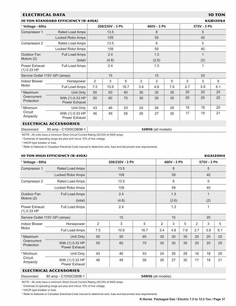
K-Series Packaged Gas / Electric 7.5 to 12.5 Ton / Page 37
ELECTRICAL DATA 10 TON10 TON STANDARD EFFICIENCY (R-410A) KGB120S41 Voltage - 60hz 208/230V - 3 Ph 460V - 3 Ph 575V - 3 PhCompressor 1 Rated Load Amps 13.5 8 5
Locked Rotor Amps 109 59 40Compressor 2 Rated Load Amps 13.5 8 5
Locked Rotor Amps 109 59 40Outdoor Fan Motors (2)
Full Load Amps 2.4 1.3 1(total) (4.8) (2.6) (2)
Power Exhaust (1) 0.33 HP
Full Load Amps 2.4 1.3 1
Service Outlet 115V GFI (amps) 15 15 20Indoor Blower Motor
Horsepower 2 3 5 2 3 5 2 3 5Full Load Amps 7.5 10.6 16.7 3.4 4.8 7.6 2.7 3.9 6.1
2 Maximum Overcurrent Protection
Unit Only 50 50 60 30 30 35 20 20 25
With (1) 0.33 HP Power Exhaust
50 60 70 30 30 35 20 20 25
3 Minimum Circuit Ampacity
Unit Only 43 46 53 24 26 29 16 18 20
With (1) 0.33 HP Power Exhaust
46 49 56 26 27 30 17 19 21
ELECTRICAL ACCESSORIES
Disconnect 80 amp - C1DISC080B-1 54W56 (all models)NOTE - All units have a minimum Short Circuit Current Rating (SCCR) of 5000 amps.1 Extremes of operating range are plus and minus 10% of line voltage.2 HACR type breaker or fuse.3 Refer to National or Canadian Electrical Code manual to determine wire, fuse and disconnect size requirements.
10 TON HIGH EFFICIENCY (R-410A) KGA120H4
1 Voltage - 60hz 208/230V - 3 Ph 460V - 3 Ph 575V - 3 Ph
Compressor 1 Rated Load Amps 13.5 8 5
Locked Rotor Amps 109 59 40
Compressor 2 Rated Load Amps 13.5 8 5
Locked Rotor Amps 109 59 40
Outdoor Fan Motors (2)
Full Load Amps 2.4 1.3 1
(total) (4.8) (2.6) (2)
Power Exhaust (1) 0.33 HP
Full Load Amps 2.4 1.3 1
Service Outlet 115V GFI (amps) 15 15 20
Indoor Blower Motor
Horsepower 2 3 5 2 3 5 2 3 5
Full Load Amps 7.5 10.6 16.7 3.4 4.8 7.6 2.7 3.9 6.12 Maximum
Overcurrent Protection
Unit Only 50 50 60 30 30 35 20 20 25
With (1) 0.33 HP Power Exhaust
50 60 70 30 30 35 20 20 25
3 Minimum Circuit Ampacity
Unit Only 43 46 53 24 26 29 16 18 20
With (1) 0.33 HP Power Exhaust
46 49 56 26 27 30 17 19 21
ELECTRICAL ACCESSORIES
Disconnect 80 amp - C1DISC080B-1 54W56 (all models)NOTE - All units have a minimum Short Circuit Current Rating (SCCR) of 5000 amps.1 Extremes of operating range are plus and minus 10% of line voltage.2 HACR type breaker or fuse.3 Refer to National or Canadian Electrical Code manual to determine wire, fuse and disconnect size requirements.

K-Series Packaged Gas / Electric 7.5 to 12.5 Ton / Page 38
12.5 TON STANDARD EFFICIENCY (R-410A) KGB150S41 Voltage - 60hz 208/230V - 3 Ph 460V - 3 Ph 575V - 3 PhCompressor 1 Rated Load Amps 19.6 8.2 6.6
Locked Rotor Amps 136 66.1 55.3Compressor 2 Rated Load Amps 22.4 10.6 7.7
Locked Rotor Amps 149 75 54Outdoor Fan Motors (2)
Full Load Amps 3 1.5 1.2(total) (6) (3) (2.4)
Power Exhaust (1) 0.33 HP
Full Load Amps 2.4 1.3 1
Service Outlet 115V GFI (amps) 15 15 20Indoor Blower Motor
Horsepower 2 3 5 2 3 5 2 3 5Full Load Amps 7.5 10.6 16.7 3.4 4.8 7.6 2.7 3.9 6.1
2 Maximum Overcurrent Protection
Unit Only 80 80 90 35 35 40 25 30 30With (1) 0.33 HP
Power Exhaust80 80 90 35 40 40 30 30 30
3 Minimum Circuit Ampacity
Unit Only 62 65 71 28 30 33 22 23 25With (1) 0.33 HP
Power Exhaust64 67 73 30 31 34 23 24 26
ELECTRICAL ACCESSORIES
Disconnect 80 amp - C1DISC080B-1 54W56 (all models)NOTE - All units have a minimum Short Circuit Current Rating (SCCR) of 5000 amps.1 Extremes of operating range are plus and minus 10% of line voltage.2 HACR type breaker or fuse.3 Refer to National or Canadian Electrical Code manual to determine wire, fuse and disconnect size requirements.
ELECTRICAL DATA
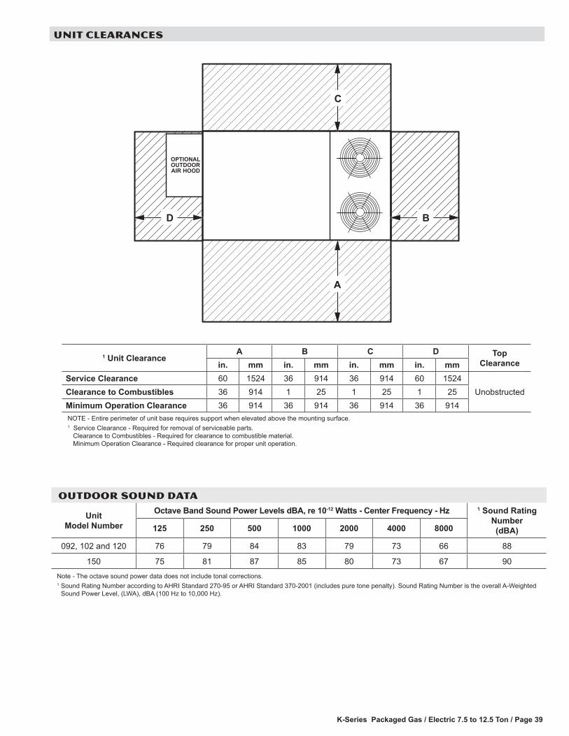
K-Series Packaged Gas / Electric 7.5 to 12.5 Ton / Page 39
A
C
DBD
OPTIONALOUTDOORAIR HOOD
D
1 Unit ClearanceA B C D Top
Clearancein. mm in. mm in. mm in. mmService Clearance 60 1524 36 914 36 914 60 1524
UnobstructedClearance to Combustibles 36 914 1 25 1 25 1 25Minimum Operation Clearance 36 914 36 914 36 914 36 914NOTE - Entire perimeter of unit base requires support when elevated above the mounting surface.1 Service Clearance - Required for removal of serviceable parts. Clearance to Combustibles - Required for clearance to combustible material. Minimum Operation Clearance - Required clearance for proper unit operation.
UNIT CLEARANCES
OUTDOOR SOUND DATA
Unit Model Number
Octave Band Sound Power Levels dBA, re 10-12 Watts - Center Frequency - Hz 1 Sound Rating Number (dBA)125 250 500 1000 2000 4000 8000
092, 102 and 120 76 79 84 83 79 73 66 88
150 75 81 87 85 80 73 67 90Note - The octave sound power data does not include tonal corrections.1 Sound Rating Number according to AHRI Standard 270-95 or AHRI Standard 370-2001 (includes pure tone penalty). Sound Rating Number is the overall A-Weighted
Sound Power Level, (LWA), dBA (100 Hz to 10,000 Hz).
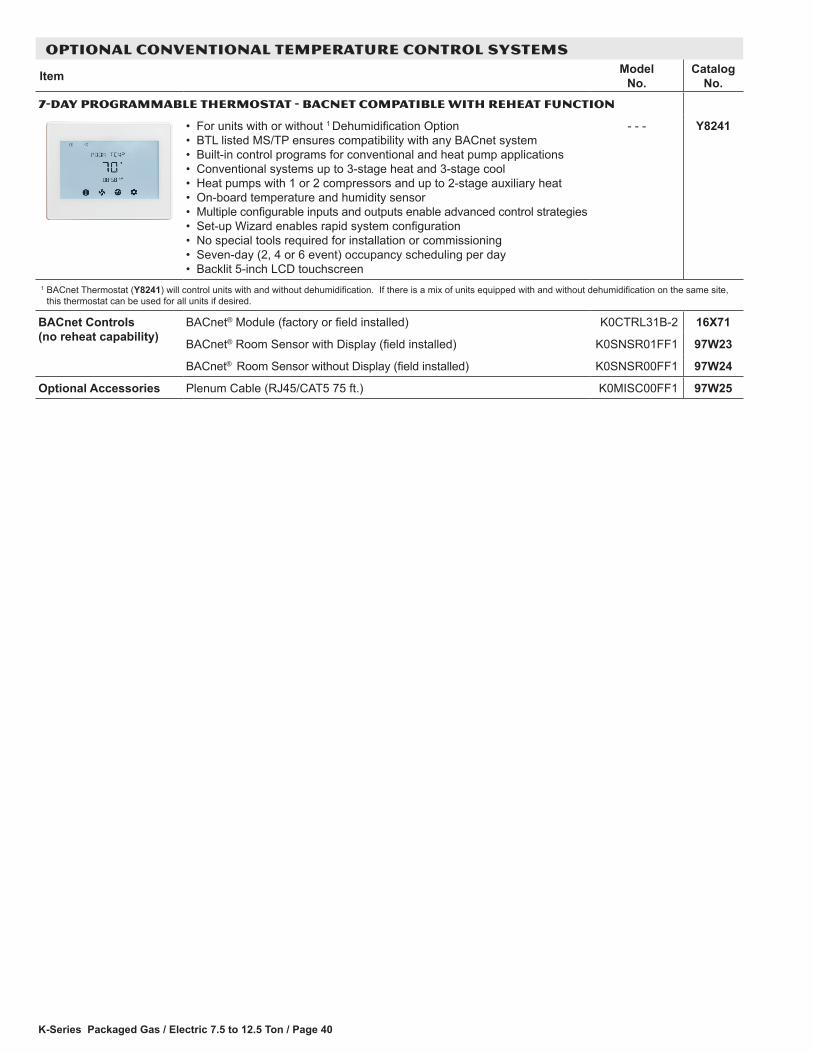
K-Series Packaged Gas / Electric 7.5 to 12.5 Ton / Page 40
OPTIONAL CONVENTIONAL TEMPERATURE CONTROL SYSTEMS
Item Model No.
Catalog No.
7-DAY PROGRAMMABLE THERMOSTAT - BACNET COMPATIBLE WITH REHEAT FUNCTION
• For units with or without 1 Dehumidification Option• BTL listed MS/TP ensures compatibility with any BACnet system• Built-in control programs for conventional and heat pump applications• Conventional systems up to 3-stage heat and 3-stage cool• Heat pumps with 1 or 2 compressors and up to 2-stage auxiliary heat• On-board temperature and humidity sensor• Multiple configurable inputs and outputs enable advanced control strategies• Set-up Wizard enables rapid system configuration• No special tools required for installation or commissioning• Seven-day (2, 4 or 6 event) occupancy scheduling per day• Backlit 5-inch LCD touchscreen
- - - Y8241
1 BACnet Thermostat (Y8241) will control units with and without dehumidification. If there is a mix of units equipped with and without dehumidification on the same site, this thermostat can be used for all units if desired.
BACnet Controls (no reheat capability)
BACnet® Module (factory or field installed) K0CTRL31B-2 16X71
BACnet® Room Sensor with Display (field installed) K0SNSR01FF1 97W23
BACnet® Room Sensor without Display (field installed) K0SNSR00FF1 97W24
Optional Accessories Plenum Cable (RJ45/CAT5 75 ft.) K0MISC00FF1 97W25

K-Series Packaged Gas / Electric 7.5 to 12.5 Ton / Page 41
OPTIONS / ACCESSORIES
Model Number Shipping Weightlbs. kg
ECONOMIZER / OUTDOOR AIR / EXHAUSTEconomizerEconomizer Dampers 60 27Barometric Relief Dampers (downflow) 8 4Barometric Relief Damper Hood (downflow) 25 11Outdoor Air Hood (downflow) 23 10Outdoor Air DampersOutdoor Air Damper Section - Automatic 51 23Outdoor Air Damper Section - Manual 39 18Power Exhaust 31 14GAS HEAT EXCHANGER (NET WEIGHT)Medium Heat (adder over standard heat) 9 4High Heat (adder over standard heat) 32 15DEHUMIDIFICATION SYSTEM Dehumidification Option 10 5single zone vav supply fan SUPPLY AIR BLOWER OPTIONVariable Frequency Drive (VFD) and associated components 10 5ROOF CURBSHybrid Roof Curbs, Downflow8 in. height 60 2714 in. height 85 3918 in. height 100 4524 in. height 125 57Adjustable Pitch Curb, Downflow14 in. height 191 82CEILING DIFFUSERSStep-Down RTD11-95S 118 54
RTD11-135S 135 61RTD11-185S 168 76
Flush FD11-95S 118 54FD11-135S 135 61FD11-185S 168 76
Transitions C1DIFF30B-1 30 14C1DIFF31B-1 32 15C1DIFF32B-1 36 16
PACKAGINGLTL Packaging (less than truck load) 105 48
WEIGHT DATA
Model Number Outdoor Coil
Net Shipping Outdoor Coil
Net Shippinglbs. kg lbs. kg lbs. kg lbs. kg
092H Base Unit Eco-Last™ 1100 499 1185 538 - - - - - - - - - - - - - - -092H Max. Unit Eco-Last™ 1251 567 1336 606 - - - - - - - - - - - - - - -102H Base Unit Eco-Last™ 1107 502 1192 541 - - - - - - - - - - - - - - -102H Max. Unit Eco-Last™ 1258 571 1343 609 - - - - - - - - - - - - - - -120H Base Unit Eco-Last™ 1142 518 1227 557 - - - - - - - - - - - - - - -120H Max. Unit Eco-Last™ 1293 586 1378 625 - - - - - - - - - - - - - - -092S Base Unit Eco-Last™ 918 416 1003 455 Fin/Tube 975 442 1060 480092S Max. Unit Eco-Last™ 1069 485 1154 523 Fin/Tube 1126 510 1211 549102S Base Unit Eco-Last™ 938 425 1023 464 Fin/Tube 995 451 1080 489102S Max. Unit Eco-Last™ 1089 494 1174 533 Fin/Tube 1146 519 1231 558120S Base Unit Eco-Last™ 1002 454 1087 493 Fin/Tube 1073 486 1158 525120S Max. Unit Eco-Last™ 1153 523 1238 561 Fin/Tube 1224 555 1309 593150S Base Unit - - - - - - - - - - - - - - - Fin/Tube 1132 513 1217 551150S Max. Unit - - - - - - - - - - - - - - - Fin/Tube 1282 581 1367 619

K-Series Packaged Gas / Electric 7.5 to 12.5 Ton / Page 42
DIMENSIONS - UNIT
Model No.
CORNER WEIGHTS CENTER OF GRAVITYAA BB CC DD EE FF
Base Max. Base Max. Base Max. Base Max. Base Max. Base Max.lbs. kg lbs. kg lbs. kg lbs. kg lbs. kg lbs. kg lbs. kg lbs. kg in. mm in. mm in. mm in. mm
092S 236 107 325 147 201 91 264 120 218 99 278 125 264 120 353 160 44-1/2 1130 43-1/2 1105 24-1/2 622 25-1/2 648092H 282 128 328 149 241 109 272 123 261 118 290 131 316 143 361 164 44-1/2 1130 43-1/2 1105 24-1/2 622 25-1/2 648102S 241 109 332 150 205 93 269 122 222 101 282 127 270 122 359 163 44-1/2 1130 43-1/2 1105 24-1/2 622 25-1/2 648102H 284 129 330 150 242 110 273 124 263 119 291 132 318 144 363 165 44-1/2 1130 43-1/2 1105 24-1/2 622 25-1/2 648120S 255 116 344 155 215 97 276 124 231 105 292 132 285 129 378 171 44 1118 43 1092 24-3/4 629 25-3/4 654120H 295 134 342 155 249 113 279 127 268 122 296 134 330 150 375 170 44 1118 43 1092 24-3/4 629 25-3/4 654150S 275 125 321 146 232 105 263 119 253 115 282 128 312 142 358 162 44 1118 43 1092 24 610 25 635Base Unit - The unit with NO OPTIONS. Max. Unit - The unit with ALL OPTIONS Installed. (Economizer, etc.)
END VIEW
60-1/8(1527)
58-1/8
46-7/8(1191)
3-1/2(89)
43-3/8(1102)
(1476)
(762)
(762)
(394)
SIDE VIEW(Horizontal Openings)
HORIZONTALRETURN AIR
OPENING
HORIZONTALSUPPLY AIR
OPENING
CONDENSATEDRAIN (BACK) 5-3/8
(137)6-1/8(156)
12-1/8(308)
1-5/8(41)
31-1/2(800)
66-3/8(1686)
15-1/2(394)
3015-1/2
30
(273)10-3/4
BASE60-1/8 (1527) CENTER OF
GRAVITY
TOP VIEW
BOTTOM RETURNAIR OPENING
24(610)
5-5/8(143)
6-1/8(156)
6-1/8(156)
6-5/8(168)
28(711)
27(686)
20(508)
AA
DD
EEFF
BOTTOMCONDENSATE
101-1/4(2572)
BB
CC
BOTTOM SUPPLYAIR OPENING
34-7/8(886)
BASE
7 (178)
7 (178)
BOTTOMPOWER ENTRY5-1/2 (140) Dia.
SIDE VIEW
LIFTING HOLES(FOR RIGGING)
101-1/4(2572)
99-1/4(2521)OPTIONAL DISCONNECT
(FACTORY INSTALLED)
1(25)
34-7/8(886)
5-3/8(137) 18-1/2
(470)
46-7/8(1191)
FORKLIFT SLOTS(BOTH SIDES)
CONDENSATEDRAIN (FRONT)
39-7/8(1013)
GAS SUPPLYINLET FLUE
OUTLET
ELECTRICINLETS

K-Series Packaged Gas / Electric 7.5 to 12.5 Ton / Page 43
DIMENSIONS - ACCESSORIES
OUTDOOR AIR HOOD DETAIL
EXHAUST AIR HOOD(Furnished, Field Installed)
OUTDOOR AIR HOOD(Furnished with Economizer or
Outdoor Air Damper)
21−3/8(543)
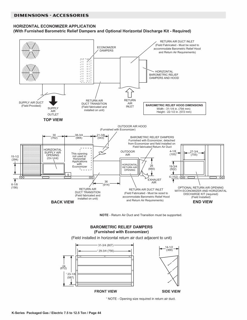
K-Series Packaged Gas / Electric 7.5 to 12.5 Ton / Page 44
DIMENSIONS - ACCESSORIES
BAROMETRIC RELIEF DAMPERSFurnished with Economizer, detached from Economizer and field installed on
Field fabricated Return Air Duct
(On Unit)
BACK VIEW
HORIZONTALSUPPLY AIR
OPENING
(Field Installed)
END VIEW
This opening not used in Horizontal
Applicationswith
Economizer
HORIZONTAL ECONOMIZER APPLICATION(With Furnished Barometric Relief Dampers and Optional Horizontal Discharge Kit - Required)
NOTE - Return Air Duct and Transition must be supported.
BAROMETRIC RELIEF HOOD DIMENSIONSWidth - 31-1/4 in. (794 mm)Height - 22-1/2 in. (572 mm)
TOP VIEW
DUCT TRANSITION(Field fabricated and
installed on unit)
ECONOMIZERDAMPERS
RETURNAIR
INLETSUPPLYAIR
OUTLET
RETURN AIR DUCT INLET(Field Fabricated - Must be sized to
accommodate Barometric Relief Hoodand Return Air Requirements)
RETURN AIRDUCT TRANSITION(Field fabricated and
installed on unit)
OUTDOOR AIR HOOD(Furnished with Economizer)
EXHAUSTAIR
OUTDOORAIR
SUPPLY AIR DUCT(Field Provided)
HORIZONTALBAROMETRIC RELIEF DAMPERS AND HOOD
OPTIONAL RETURN AIR OPENINGWITH ECONOMIZER AND HORIZONTAL
DISCHARGE KIT (required)
RETURN AIR
HORIZONTALRETURN AIR
OPENING
RETURN AIR DUCT INLET(Field Fabricated - Must be sized to
accommodate Barometric Relief Hoodand Return Air Requirements)
BAROMETRIC RELIEF DAMPERS(Furnished with Economizer)
(Field installed in horizontal return air duct adjacent to unit)
FRONT VIEW SIDE VIEW
1 NOTE - Opening size required in return air duct.
1 23-1/8 (587)
24(612)
31-3/4 (807)14-1/2(368)1 29-3/4 (756)
(984)38-3/4
(762)
(394)
6-1/8(156)
15-1/2
30
27-3/4(705)
6 (152)
4-1/8(105)
19-3/4(502)
21-3/8(543)
26(660)
36(914)
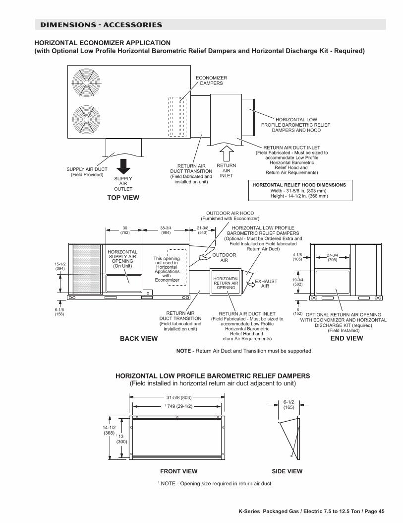
K-Series Packaged Gas / Electric 7.5 to 12.5 Ton / Page 45
DIMENSIONS - ACCESSORIES
(On Unit)
BACK VIEW
HORIZONTALSUPPLY AIR
OPENING
(Field Installed)
END VIEW
This opening not used in Horizontal
Applicationswith
Economizer
NOTE - Return Air Duct and Transition must be supported.
TOP VIEW
DUCT TRANSITION(Field fabricated and
installed on unit)
ECONOMIZERDAMPERS
RETURNAIR
INLETSUPPLYAIR
OUTLET
RETURN AIRDUCT TRANSITION(Field fabricated and
installed on unit)
OUTDOOR AIR HOOD(Furnished with Economizer)
EXHAUSTAIR
OUTDOORAIR
HORIZONTALRETURN AIR
OPENING
SUPPLY AIR DUCT(Field Provided)
OPTIONAL RETURN AIR OPENINGWITH ECONOMIZER AND HORIZONTAL
DISCHARGE KIT (required)
RETURN AIR
HORIZONTAL ECONOMIZER APPLICATION(with Optional Low Profile Horizontal Barometric Relief Dampers and Horizontal Discharge Kit - Required)
HORIZONTAL LOWPROFILE BAROMETRIC RELIEF
DAMPERS AND HOOD
RETURN AIR DUCT INLET(Field Fabricated - Must be sized to
accommodate Low ProfileHorizontal Barometric
Relief Hood and Return Air Requirements)
HORIZONTAL LOW PROFILEBAROMETRIC RELIEF DAMPERS
(Optional - Must be Ordered Extra andField Installed on Field fabricated
Return Air Duct)
RETURN AIR DUCT INLET(Field Fabricated - Must be sized to
accommodate Low ProfileHorizontal Barometric
Relief Hood and eturn Air Requirements)
HORIZONTAL LOW PROFILE BAROMETRIC RELIEF DAMPERS(Field installed in horizontal return air duct adjacent to unit)
FRONT VIEW SIDE VIEW
1 749 (29-1/2)
1 NOTE - Opening size required in return air duct.
(984)38-3/4
(762)
(394)
6-1/8(156)
15-1/2
30
27-3/4(705)
6(152)
4-1/8(105)
19-3/4(502)
21-3/8(543)
HORIZONTAL RELIEF HOOD DIMENSIONSWidth - 31-5/8 in. (803 mm)Height - 14-1/2 in. (368 mm)
1 13(300)
14-1/2(368)
31-5/8 (803)6-1/2(165)
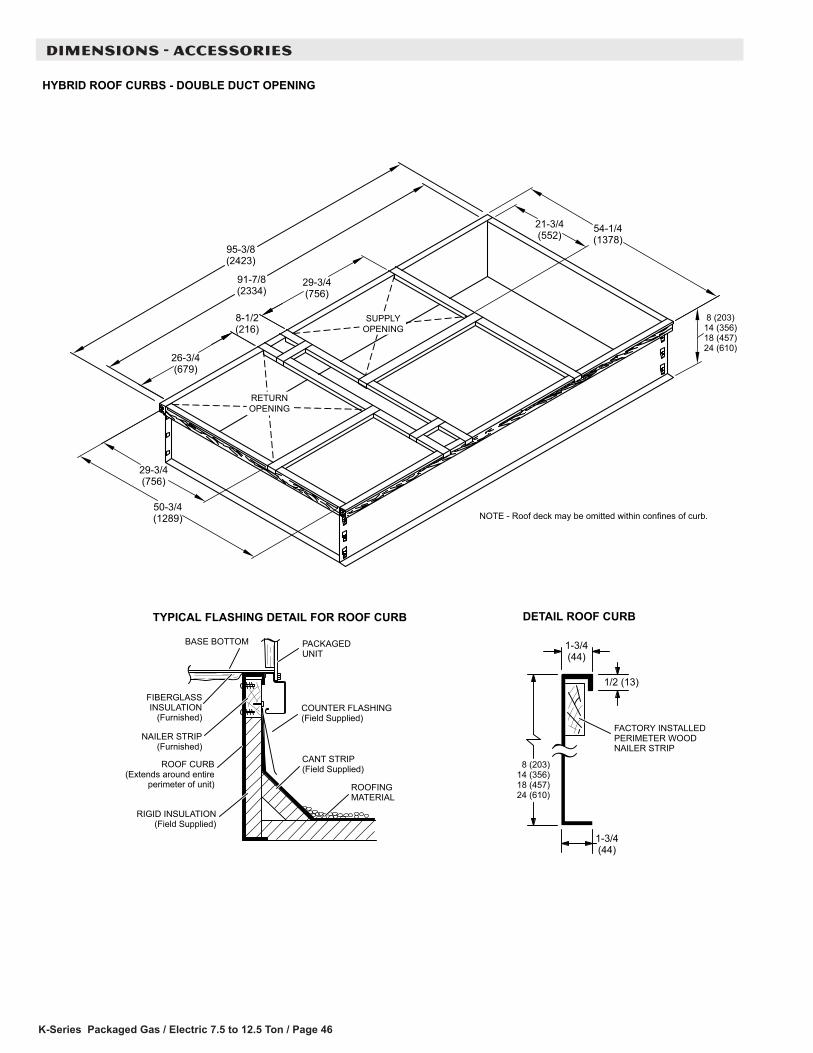
K-Series Packaged Gas / Electric 7.5 to 12.5 Ton / Page 46
DIMENSIONS - ACCESSORIES
NOTE - Roof deck may be omitted within confines of curb.
TYPICAL FLASHING DETAIL FOR ROOF CURB
ROOF CURB(Extends around entire
perimeter of unit)
FIBERGLASSINSULATION
(Furnished)COUNTER FLASHING(Field Supplied)
BASE BOTTOM
RIGID INSULATION(Field Supplied)
ROOFINGMATERIAL
CANT STRIP(Field Supplied)
PACKAGEDUNIT
NAILER STRIP(Furnished)
DETAIL ROOF CURB
FACTORY INSTALLEDPERIMETER WOODNAILER STRIP
SUPPLYOPENING
HYBRID ROOF CURBS - DOUBLE DUCT OPENING
RETURNOPENING
8 (203)14 (356)18 (457)24 (610)
1-3/4(44)
1/2 (13)
1-3/4(44)
8 (203)14 (356)18 (457)24 (610)
50-3/4(1289)
29-3/4(756)
95-3/8(2423)
91-7/8(2334)
29-3/4(756)
26-3/4(679)
8-1/2(216)
21-3/4(552)
54-1/4(1378)
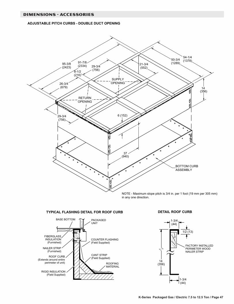
K-Series Packaged Gas / Electric 7.5 to 12.5 Ton / Page 47
DIMENSIONS - ACCESSORIES
TYPICAL FLASHING DETAIL FOR ROOF CURB
ROOF CURB(Extends around entire
perimeter of unit)
FIBERGLASSINSULATION
(Furnished)COUNTER FLASHING(Field Supplied)
BASE BOTTOM
RIGID INSULATION(Field Supplied)
ROOFINGMATERIAL
CANT STRIP(Field Supplied)
PACKAGEDUNIT
NAILER STRIP(Furnished)
DETAIL ROOF CURB
FACTORY INSTALLEDPERIMETER WOODNAILER STRIP
RETURNOPENING
ADJUSTABLE PITCH CURBS - DOUBLE DUCT OPENING
SUPPLYOPENING
BOTTOM CURBASSEMBLY
NOTE - Maximum slope pitch is 3/4 in. per 1 foot (19 mm per 305 mm)in any one direction.
29-3/4(756)
29-3/4(756)
26-3/4(679)
8-1/2(216)
21-3/4(552)
54-1/4(1378)50-3/4
(1289)
14 (356)
1-3/4(44)
1/2 (13)
1-3/4(44)
91-7/8(2334)95-3/8
(2423)
14 (356)
6 (152)
37(940)
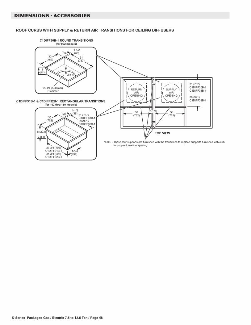
K-Series Packaged Gas / Electric 7.5 to 12.5 Ton / Page 48
DIMENSIONS - ACCESSORIES
ROOF CURBS WITH SUPPLY & RETURN AIR TRANSITIONS FOR CEILING DIFFUSERS
8 (203)
2 (51)
17-3/4(451)
27-3/4 (705)C1DIFF31B-135-3/4 (908)
C1DIFF32B-1
31 (787)C1DIFF31B-139 (991)C1DIFF32B-1
C1DIFF31B-1 & C1DIFF32B-1 RECTANGULAR TRANSITIONS(for 102 thru 150 models)
30(762)
1-1/2(38)Typ.
20 IN. (508 mm)Diameter
31(787)
8(203)
30(762)
1-1/2(38)Typ.
C1DIFF30B-1 ROUND TRANSITIONS(for 092 models)
2 (51)
TOP VIEW
RETURNAIR
OPENING
31 (787)C1DIFF30B-1C1DIFF31B-1
39 (991)C1DIFF32B-1
30(762)
30(762)
SUPPLYAIR
OPENING
NOTE - These four supports are furnished with the transitions to replace supports furnished with curb for proper transition spacing.
5 (127)
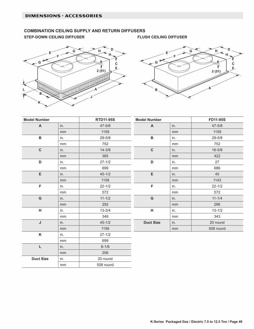
K-Series Packaged Gas / Electric 7.5 to 12.5 Ton / Page 49
DIMENSIONS - ACCESSORIES
COMBINATION CEILING SUPPLY AND RETURN DIFFUSERSSTEP-DOWN CEILING DIFFUSER FLUSH CEILING DIFFUSER
L A
J
C
HH
DG
G
FE
B
K
2 (51)
A
C
HH
DG
G
FE
B
2 (51)
Model Number RTD11-95SA in. 47-5/8
mm 1159B in. 29-5/8
mm 752C in. 14-3/8
mm 365D in. 27-1/2
mm 699E in. 45-1/2
mm 1158F in. 22-1/2
mm 572G in. 11-1/2
mm 292H in. 13-3/4
mm 349J in. 45-1/2
mm 1156K in. 27-1/2
mm 699L in. 8-1/8
mm 206Duct Size in. 20 round
mm 508 round
Model Number FD11-95SA in. 47-5/8
mm 1159B in. 29-5/8
mm 752C in. 16-5/8
mm 422D in. 27
mm 686E in. 45
mm 1143F in. 22-1/2
mm 572G in. 11-1/4
mm 286H in. 13-1/2
mm 343Duct Size in. 20 round
mm 508 round

K-Series Packaged Gas / Electric 7.5 to 12.5 Ton / Page 50
DIMENSIONS - ACCESSORIES
COMBINATION CEILING SUPPLY AND RETURN DIFFUSERSRESUFFID GNILIEC HSULFRESUFFID GNILIEC NWOD-PETS
L
A
C
HJG
FE
B
M
N
K
DG
2 (51)
A
C
HJG
FE
B
K
DG
2 (51)
Model Number RTD11-135S RTD11-185SA in. 47-5/8 47-5/8
mm 1210 1210B in. 35-5/8 47-5/8
mm 905 1210C in. 20-5/8 24-5/8
mm 524 625D in. 33-1/2 45-1/2
mm 851 1156E in. 45-1/2 45-1/2
mm 1156 1156F in. 4-1/2 4-1/2
mm 114 114G in. 18 18
mm 457 457H in. 2-1/2 2-1/2
mm 64 64J in. 28 36
mm 711 914K in. 2-3/4 4-3/4
mm 70 121L in. 45-1/2 45-1/2
mm 1156 1156M in. 33-1/2 45-1/2
mm 851 1156N in. 9-1/8 10-1/8
mm 232 257Duct Size in. 18 x 28 18 x 36
mm 457 x 711 457 x 914
Model Number FD11-135S FD11-185SA in. 47-5/8 47-5/8
mm 1210 1210B in. 35-5/8 47-5/8
mm 905 1210C in. 23-1/4 29-1/4
mm 591 743D in. 33 45
mm 838 1143E in. 45 45
mm 1143 1143F in. 4-1/2 4-1/2
mm 114 114G in. 18 18
mm 457 457H in. 2-1/4 2-1/4
mm 57 57J in. 28 36
mm 711 914K in. 2-1/2 4-1/2
mm 64 114Duct Size in. 18 x 28 18 x 36
mm 457 x 711 457 x 914

REVISIONS
REVISIONS
Section Description
Dehumidification Rating Tables Corrected Outdoor Air Temperature Entering Outdoor Coil ranges.
NOTE - Due to Allied Commercial ongoing commitment to quality, Specifications, Ratings and Dimensions subject to change without notice and without incurring liability. Improper installation, adjustment, alteration, service or maintenance can cause property damage or personal injury. Installation and service must be performed by a qualified installer and servicing agency.
©2019 Allied Air Enterprises LLC, a Lennox International Inc. Company
Visit us at www.allied-commercial.com For the latest technical information, visit us at www.allied-commercial.com Contact us at 1-800-448-5872