Embed Size (px)
Citation preview

kg
ABB i-bus® KNX Binary Inputs BE/S Product Manual


ABB i-bus® KNX Contents
© 2011 ABB STOTZ-KONTAKT GmbH i
Contents Page
1 General 5
1.1 Using the product manual.....................................................................5 1.1.1 Structure of the product manual.........................................................5 1.1.2 Notes..................................................................................................6 1.2 Product and functional overview...........................................................7 1.2.1 Short overview ...................................................................................8
2 Device technology 9
2.1 Binary Input with manual operation, 4-fold, 230 V AC/DC, MDRC ................................................................9
2.1.1 Technical data....................................................................................9 2.1.2 Connection schematic BE/S 4.230.2.1 ............................................11 2.1.3 Dimensional drawing BE/S 4.230.2.1 ..............................................12 2.2 Binary input with manual operation,
4-fold, contact scanning, MDRC.........................................................13 2.2.1 Technical data..................................................................................13 2.2.2 Connection schematic BE/S 4.20.2.1 ..............................................15 2.2.3 Dimensional drawing BE/S 4.20.2.1 ................................................16 2.3 Binary Input with manual operation,
8-fold, 230 V AC/DC, MDRC ..............................................................17 2.3.1 Technical data..................................................................................17 2.3.2 Connection schematic BE/S 8.230.2.1 ............................................19 2.3.3 Dimensional drawing BE/S 8.230.2.1 ..............................................20 2.4 Binary Input with manual operation,
8-fold, contact scanning, MDRC.........................................................21 2.4.1 Technical data..................................................................................21 2.4.2 Connection schematic BE/S 8.20.2.1 ..............................................23 2.4.3 Dimensional drawing BE/S 8.20.2.1 ................................................24 2.5 Assembly and installation ...................................................................25 2.6 Manual operation ................................................................................27 2.6.1 Display elements..............................................................................28 2.6.2 Operating controls............................................................................29
3 Commissioning 31
3.1 Overview.............................................................................................31 3.1.1 Conversion .......................................................................................32 3.1.1.1 Procedure ......................................................................................33 3.1.2 Copy and exchange parameter settings ..........................................34 3.1.2.1 Procedure ......................................................................................35 3.1.2.2 Copy/Exchange channels dialog ...................................................36 3.2 Parameters .........................................................................................38 3.2.1 Parameter window Device information ............................................39 3.2.2 Parameter window General .............................................................40 3.2.3 Parameter window Manual ..............................................................43 3.2.4 Parameter window Push button for manual operation.....................46 3.2.5 Parameter window Input LED ..........................................................47 3.2.6 Communication objects General......................................................48 3.2.7 Parameter window Enable Inputs A…X...........................................50

ABB i-bus® KNX Contents
© 2011 ABB STOTZ-KONTAKT GmbH ii
3.2.8 Operating mode Switch sensor/Fault monitoring input ................... 52 3.2.8.1 Parameter window A: Switch sensor ............................................ 53 3.2.8.1.1 Parameter Distinction between short and
long operation – no..................................................................... 56 3.2.8.1.2 Parameter Distinction between short and
long operation – yes ................................................................... 61 3.2.8.1.3 Special function Fault monitoring input ...................................... 63 3.2.8.2 Communication objects Switch sensor ......................................... 66 3.2.9 Operating mode Switch/Dim sensor ................................................ 68 3.2.9.1 Parameter window A: Switch/Dim sensor ..................................... 69 3.2.9.2 Operating mode Switch/Dim sensor ............................................. 74 3.2.10 Operating mode Blind sensor .......................................................... 76 3.2.10.1 Parameter window A: Blind sensor ............................................... 77 3.2.10.2 Communication objects Blind sensor............................................ 81 3.2.11 Operating mode Value/Forced operation ....................................... 84 3.2.11.1 Parameter window A: Value/Forced op. ....................................... 85 3.2.11.1.1 Parameter Distinction between short and
long operation – no..................................................................... 88 3.2.11.1.2 Parameter Distinction between short and
long operation – yes ................................................................... 93 3.2.11.2 Communication objects Value/forced operation ........................... 94 3.2.12 Operating mode Control scene........................................................ 96 3.2.12.1 Parameter window A: Control scene ............................................ 97 3.2.12.2 Communication objects Control scene ....................................... 101 3.2.13 Operating mode Switching sequences .......................................... 105 3.2.13.1 Parameter window A: Switching sequences ............................... 106 3.2.13.2 Communication objects Switch sequences ................................ 112 3.2.14 Operating mode Multiple operation ............................................... 115 3.2.14.1 Parameter window A: Multiple operation .................................... 116 3.2.14.2 Communication objects Multiple operation ................................. 120 3.2.15 Operating mode Counter ............................................................... 123 3.2.15.1 Counting pulses .......................................................................... 123 3.2.15.2 Behaviour of the counter readings after a download .................. 124 3.2.15.3 Behaviour of the counter readings bus voltage failure ............... 124 3.2.15.4 Specific feature differences between main counter and
differential counter ...................................................................... 125 3.2.15.5 Parameter window A: Counter .................................................... 126 3.2.15.6 Parameter window A: Differential counter .................................. 132 3.2.15.7 Communication objects A: Counter ........................................... 135
4 Planning and application 139
4.1 Block diagram Switch sensor ........................................................... 139 4.2 Block diagram Switch/Dim sensor ................................................... 140 4.3 Block diagram Blind sensor.............................................................. 141 4.3.1 Block diagram Blind sensor with external Blind actuator .............. 142 4.4 Block diagram Value/Forced operation............................................ 143 4.5 Block diagram Control scene ........................................................... 144 4.6 Block diagram Switching sequences ............................................... 145 4.7 Block diagram Multiple operation ..................................................... 146 4.8 Block diagram Counter..................................................................... 147

ABB i-bus® KNX Contents
© 2011 ABB STOTZ-KONTAKT GmbH iii
A Appendix 149
A.1 Scope of delivery ..............................................................................149 A.2 Input 4 bit dimming telegram: ...........................................................150 A.3 Gray code .........................................................................................151 A.4 Code table Scene (8 bit) ...................................................................152 A.5 Ordering Information.........................................................................153 A.6 Notes.................................................................................................154 A.7 Notes.................................................................................................155 A.8 Notes.................................................................................................156


ABB i-bus® KNX General
© 2011 ABB STOTZ-KONTAKT GmbH 5
1 General
All ABB i-bus® KNX devices are as easy and intuitive to operate as possible. Accordingly, a clear and comfortable intelligent building installation can be easily realized.
The Binary Inputs BE/S fulfil the individual needs both in functional buildings as well as in the private residential sector.
1.1 Using the product manual
This manual provides you with detailed technical information relating to the Binary Inputs, their installation and programming. The application of the device is described using examples.
This manual is divided into the following sections:
Chapter 1 General
Chapter 2 Device technology
Chapter 3 Commissioning
Chapter 4 Planning and application
Chapter A Appendix
1.1.1 Structure of the product manual
All parameters are described in chapter 3.
Note
In this product manual, both 4-fold and 8-fold Binary Inputs are described. These devices each have four or eight binary inputs. However, as the functions for all binary inputs are identical, only the functions of input A will be described.
Should the details in the product manual refer to all binary inputs, 4-fold corresponds to inputs A…D and 8-fold corresponds to inputs A…H and the designation inputs A…X is used.

ABB i-bus® KNX General
© 2011 ABB STOTZ-KONTAKT GmbH 6
1.1.2 Notes
Notes and safety instructions are represented as follows in this product manual:
Note
Tips for usage and operation
Examples
Application examples, installation examples, programming examples
Important
These safety instructions are used as soon as there is danger of a malfunction without risk of damage or injury.
Caution These safety instructions are used if there is a danger of damage with inappropriate use.
Danger These safety instructions are used if there is a danger for life and limb with inappropriate use.
Danger These safety instructions are used if there is a danger to life with inappropriate use.

ABB i-bus® KNX General
© 2011 ABB STOTZ-KONTAKT GmbH 7
1.2 Product and functional overview
The binary inputs serve as interfaces for operation of KNX systems via conventional buttons/switches or for coupling of binary signals (signal contacts).
The devices feature a push button for manual operation for each input. Input states can be simulated during manual operation, so that the conventional push buttons, switches or floating contacts do not need to be connected for commissioning purposes.
The inputs are modular installation devices with a module width of 2 and 4 space units in Pro M design for installation in a distribution board. The connection to the ABB i-bus® is established using the front side bus connection terminal. The assignment of the physical addresses as well as the parameterization is carried out with Engineering Tool Software ETS3.
Note
The illustrations of the parameter windows in this manual correspond to the ETS3 parameter windows. The application program is optimised for ETS3.
The processing of the binary signals is carried out in the corresponding application program
• Binary 4f 23021/1.0, Binary 4f 2021/1.0,
• Binary 8f 23021/1.0, Binary 8f 2021/1.0

ABB i-bus® KNX General
© 2011 ABB STOTZ-KONTAKT GmbH 8
1.2.1 Short overview
Application possibilities BE/S 4.x.2.1 BE/S 8.x.2.1
Inputs 4 8
Switch sensor/Fault monitoring input
Switch/Dim sensor
Blind sensor
Value/Forced operation
Control scene
Switching sequences
Multiple operation
Counter
Parameterization options BE/S 4.x.2.1 BE/S 8.x.2.1
Inputs 4 8
Switching and dimming of lighting (also for
1-button operation)
Operation of shutters and blinds (also for 1-
button operation)
Sending of arbitrary values, e.g.
temperature values
Control and saving of light scenes
Operation of different consumers by
repeated actuation
Operation of several loads in a defined
switching sequence
Counting from impulses and actuations
Reading of floating contacts
Each Binary Input of a device can assume
one of the functions described beforehand.

ABB i-bus® KNX Device technology
© 2011 ABB STOTZ-KONTAKT GmbH 9
2 Device technology
2.1 Binary Input with manual operation, 4-fold, 230 V AC/DC, MDRC
BE/S 4.230.2.1
The 4-fold Binary Input BE/S 4.230.1 with manual operation is a rail mounted device for installation in the distribution board. The device is suitable for reading out 10…230 V AC/DC signals. Inputs A and B are independent of inputs C and D.
Buttons located on the front of the device can be used to manually simulate the input state. The status of the inputs is displayed by yellow LEDs.
The device is ready for operation after connecting the bus voltage. The Binary Input is parameterized via ETS. The connection to the KNX is implemented using the bus connection terminal on the front.
2.1.1 Technical data
Supply Bus voltage 21…32 V AC
Current consumption, bus Maximum 5 mA
Power consumption, bus Maximum 100 mW
Leakage loss, bus Maximum 800 mW at AC operation
Maximum 1.6 W at DC operation
Inputs Number 4
Permitted voltage range Un 0…265 V AC/DC
Input current In Maximum 1 mA
Signal level for 0 signal 0…2 V AC/DC
Signal level for 1 signal 7…265 V AC/DC
Permissible cable length Maximum 100 m at 1.5 mm²
Connections KNX Via bus connection terminals
Inputs Via slotted head screw terminals
Connection terminals Screw terminals 0.2…2.5 mm² stranded
0.2…4.0 mm² solid
Tightening torque Maximum 0.6 Nm
Operating and display elements Button/LED Programming For assignment of the physical address
Button /LED For toggling between manual
operation/operation via ABB i-bus® and
displays
Button /LED
(applies for all binary inputs, A…D)
For switching and display
Enclosure IP 20 To EN 60 529
Safety class II To EN 61 140
2CD
C 0
71 0
10 F
0010

ABB i-bus® KNX Device technology
© 2011 ABB STOTZ-KONTAKT GmbH 10
Isolation category Overvoltage category III to DIN EN 60 664-1
Pollution degree 2 to EN 60 664-1
KNX safety extra low voltage SELV 24 V DC
Temperature range Operation
Storage
Transport
-5 °C…+45 °C
-25 °C…+55 °C
-25 °C…+70 °C
Ambient conditions Maximum air humidity 93 %, no condensation allowed
Design Modular installation device (MDRC) Modular installation device, Pro M
Dimensions 90 x 36 x 67.5 mm (H x W x D)
Mounting width in space units 2 modules at 18 mm
Mounting depth 67.5 mm
Installation On 35 mm mounting rail To EN 60 715
Mounting position As required
Weight 0.1 kg
Housing/colour Plastic housing, grey
Approvals KNX to EN 50 090-1, -2 Certification
CE mark In accordance with the EMC guideline and
low voltage guideline
Device type Application program Maximum number of
communication objects
Maximum number of
group addresses
Maximum number of
associations
BE/S 4.230.2.1 Binary 4f 23021/…* 43 254 254
* … = current version number of the application program
Note
The ETS and the current version of the device application program are required for programming.
The current version of the application program is available for download on the Internet at www.abb.com/knx. After import it is available in the ETS under ABB/Input/Binary input 4-fold.
The device does not support the closing function of a KNX device in the ETS. If you inhibit access to all devices of the project with a BCU code, it has no effect on this device. Data can still be read and programmed.

ABB i-bus® KNX Device technology
© 2011 ABB STOTZ-KONTAKT GmbH 11
2.1.2 Connection schematic BE/S 4.230.2.1
Connection of AC voltage Connection of DC voltage
1 Label carrier 2 Button Programming 3 LED Programming 4 Bus connection terminal 5 Button Manual operation 6 LED Manual operation 7 Connection terminals 8 LED Binary input 9 Button Binary input
Important Important
When connecting AC voltage, two separate RCD (earth-leakage circuit breaker) circuits can be connected to terminals 1, 2, 3 and 4, 5, 6.
Correct polarity must be observed when the DC voltage is connected.
If incorrectly connected, the input cannot be read out and processed.
Important
Use of switch or a push-in inserts with N terminals, in conjunction with the BE/S 4.230.2.1 series Binary Inputs are absolutely necessary to ensure malfunction free operation and sufficient illumination of glow lamps on illuminated switches or plug-in inserts.
2CD
C 0
72 1
57 F
0009
2CD
C 0
72 1
61 F
0009

ABB i-bus® KNX Device technology
© 2011 ABB STOTZ-KONTAKT GmbH 12
2.1.3 Dimensional drawing BE/S 4.230.2.1
2CD
C 0
72 1
92 F
0009

ABB i-bus® KNX Device technology
© 2011 ABB STOTZ-KONTAKT GmbH 13
2.2 Binary input with manual operation, 4-fold, contact scanning, MDRC
BE/S 4.20.2.1
The 4-fold Binary Input BE/S 4.20.2.1 with manual operation is a rail mounted device for installation in the distribution board. The device is suitable for reading floating contacts. The pulsed scanning voltage is generated internally.
Buttons located on the front of the device can be used to manually simulate the input state. The status of the inputs is displayed by yellow LEDs.
The device is ready for operation after connecting the bus voltage. The Binary Input is parameterized via ETS. The connection to the KNX is implemented using the bus connection terminal on the front.
2.2.1 Technical data
Supply Bus voltage 21…32 V DC
Current consumption, bus Maximum 6 mA
Power consumption, bus Maximum 130 mW
Leakage loss, bus Maximum 130 mW
Inputs Number 4
Scanning voltage Un 35 V, pulsed
Scanning current In 0.1 mA
Scanning current In at switch on Maximum 355 mA
Permissible cable length Maximum 100 m at 1.5 mm²
Connections KNX Via bus connection terminals
Inputs Via screw terminals
Connection terminals KNX Via bus connection terminals
Inputs Via slotted head screw terminals
Operating and display elements Button/LED Programming For assignment of the physical address
Button /LED For toggling between manual
operation/operation via ABB i-bus® and
displays
Button /LED
(applies for all binary inputs, A…D)
For switching and display
Enclosure IP 20 To EN 60 529
Safety class II To EN 61 140
Isolation category Overvoltage category III to DIN EN 60 664-1
Pollution degree 2 to EN 60 664-1
KNX safety extra low voltage SELV 24 V DC
2CD
C 0
71 0
09 F
0010

ABB i-bus® KNX Device technology
© 2011 ABB STOTZ-KONTAKT GmbH 14
Temperature range Operation
Storage
Transport
-5 °C…+45 °C
-25 °C…+55 °C
-25 °C…+70 °C
Ambient conditions Maximum air humidity 93 %, no condensation allowed
Design Modular installation device (MDRC) Modular installation device, Pro M
Dimensions 90 x 36 x 67.5 mm (H x W x D)
Mounting width in space units 2 modules at 18 mm
Mounting depth 67.5 mm
Installation On 35 mm mounting rail To EN 60 715
Mounting position As required
Weight 0.1 kg
Housing/colour Plastic housing, grey
Approvals KNX to EN 50 090-1, -2 Certification
CE mark In accordance with the EMC guideline and
low voltage guideline
Device type Application program Maximum number of
communication objects
Maximum number of
group addresses
Maximum number of
associations
BE/S 4.20.2.1 Binary 4f 2021/…* 43 254 254
* … = current version number of the application program
Note
The ETS and the current version of the device application program are required for programming.
The current version of the application program is available for download on the Internet at www.abb.com/knx. After import it is available in the ETS under ABB/Input/Binary input 4-fold.
The device does not support the closing function of a KNX device in the ETS. If you inhibit access to all devices of the project with a BCU code, it has no effect on this device. Data can still be read and programmed.

ABB i-bus® KNX Device technology
© 2011 ABB STOTZ-KONTAKT GmbH 15
2.2.2 Connection schematic BE/S 4.20.2.1
1 Label carrier 2 Button Programming 3 LED Programming 4 Bus connection terminal 5 Button Manual operation 6 LED Manual operation 7 Connection terminals 8 LED Binary input 9 Button Binary input
Note
An external voltage connection to the Binary Input BE/S 4.20.2.1 is not permitted.
Terminals 3 and 4 are internally interconnected to one another.
2CD
C 0
72 1
56 F
0009

ABB i-bus® KNX Device technology
© 2011 ABB STOTZ-KONTAKT GmbH 16
2.2.3 Dimensional drawing BE/S 4.20.2.1
2CD
C 0
72 1
90 F
0009

ABB i-bus® KNX Device technology
© 2011 ABB STOTZ-KONTAKT GmbH 17
2.3 Binary Input with manual operation, 8-fold, 230 V AC/DC, MDRC
BE/S 8.230.2.1
The 8-fold Binary Input BE/S 8.230.2.1 with manual operation is a rail mounted device for installation in the distribution board. The device is suitable for reading out 10…230 V AC/DC signals.
Buttons located on the front of the device can be used to manually simulate the input state. The status of the inputs is displayed by yellow LEDs.
The device is ready for operation after connecting the bus voltage. The Binary Input is parameterized via ETS. The connection to the KNX is implemented using the bus connection terminal on the front.
2.3.1 Technical data
Supply Bus voltage 21…32 V DC
Current consumption, bus Maximum 6 mA
Power consumption, bus Maximum 120 mW
Leakage loss, bus Maximum 1.5 W at AC operation
Maximum 3.0 W at DC operation
Inputs Number 8 individual
Permitted voltage range Un 0…265 V AC/DC
Input current In Maximum 1 mA
Signal level for 0 signal 0…2 V AC/DC
Signal level for 1 signal 7…265 V AC/DC
Permissible cable length Maximum 100 m at 1.5 mm²
Connections KNX Via bus connection terminals
Inputs Using universal head screw terminals (PZ 1)
Connection terminals Screw terminal
Ferrules without/with plastic sleeves
TWIN ferrules
Tightening torque
Grid
Screw terminals with universal head (PZ 1)
0.2…4 mm² stranded, 2 x (0.2…2.5 mm²)
0.2…6 mm² solid, 2 x (0.2…4 mm²)
Without: 0.25…2.5 mm²
With: 0.25…4 mm²
0.5…2.5 mm²
Contact pin length at least 10 mm
Maximum 0.8 Nm
6.35
Operating and display elements Button/LED Programming For assignment of the physical address
Button /LED For toggling between manual
operation/operation via ABB i-bus® and
displays
Button /LED
(applies for all binary inputs, A…H)
For switching and display
2CD
C 0
71 0
12 F
0010

ABB i-bus® KNX Device technology
© 2011 ABB STOTZ-KONTAKT GmbH 18
Enclosure IP 20 To EN 60 529
Safety class II To EN 61 140
Isolation category Overvoltage category III to DIN EN 60 664-1
Pollution degree 2 to EN 60 664-1
KNX safety extra low voltage SELV 24 V DC
Temperature range Operation
Storage
Transport
-5 °C…+45 °C
-25 °C…+55 °C
-25 °C…+70 °C
Ambient conditions Maximum air humidity 93 %, no condensation allowed
Design Modular installation device (MDRC) Modular installation device, Pro M
Dimensions 90 x 72 x 67.5 mm (H x W x D)
Mounting width in space units 4 modules at 18 mm
Mounting depth 67.5 mm
Installation On 35 mm mounting rail To EN 60 715
Mounting position As required
Weight 0.2 kg
Housing/colour Plastic housing, grey
Approvals KNX to EN 50 090-1, -2 Certification
CE mark In accordance with the EMC guideline and
low voltage guideline
Device type Application program Maximum number of
communication objects
Maximum number of
group addresses
Maximum number of
associations
BE/S 8.230.2.1 Binary 8f 23021/…* 83 254 254
* … = current version number of the application program
Note
The ETS and the current version of the device application program are required for programming.
The current version of the application program is available for download on the Internet at www.abb.com/knx. After import it is available in the ETS under ABB/Input/Binary input 8-fold.
The device does not support the closing function of a KNX device in the ETS. If you inhibit access to all devices of the project with a BCU code, it has no effect on this device. Data can still be read and programmed.

ABB i-bus® KNX Device technology
© 2011 ABB STOTZ-KONTAKT GmbH 19
2.3.2 Connection schematic BE/S 8.230.2.1
Connection with AC voltage Connection with DC voltage
1 Label carrier 2 Button Programming 3 LED Programming 4 Bus connection terminal 5 Button Manual operation 6 LED Manual operation 7 Connection terminals 8 LED Binary input 9 Button Binary input
Important Important
When connecting AC voltage, up to eight separate RCD (earth-leakage circuit breaker) circuits can be connected.
Correct polarity must be observed when the DC voltage is connected.
If incorrectly connected, the input cannot be read out and processed.
Important
Use of switch or a push-in inserts with N terminals, in conjunction with the BE/S 8.230.2.1 series Binary Inputs are absolutely necessary to ensure malfunction free operation and sufficient illumination of glow lamps on illuminated switches or plug-in inserts.
2CD
C 0
72 1
59 F
0009
2CD
C 0
72 1
63 F
0009

ABB i-bus® KNX Device technology
© 2011 ABB STOTZ-KONTAKT GmbH 20
2.3.3 Dimensional drawing BE/S 8.230.2.1
2CD
C 0
72 1
96 F
0009

ABB i-bus® KNX Device technology
© 2011 ABB STOTZ-KONTAKT GmbH 21
2.4 Binary Input with manual operation, 8-fold, contact scanning, MDRC
BE/S 8.20.2.1
The 8-fold Binary Input BE/S 8.20.2.1 with manual operation is a rail mounted device for installation in the distribution board. The device is suitable for reading floating contacts. The pulsed scanning voltage is generated internally.
Buttons located on the front of the device can be used to manually simulate the input state. The status of the inputs is displayed by yellow LEDs.
The device is ready for operation after connecting the bus voltage. The Binary Input is parameterized via ETS. The connection to the KNX is implemented using the bus connection terminal on the front.
2.4.1 Technical data
Supply Bus voltage 21…32 V DC
Current consumption, bus Maximum 7 mA
Power consumption, bus Maximum 150 mW
Leakage loss, bus Maximum 150 mW
Inputs Number 8
Scanning voltage Un 35 V, pulsed
Scanning current In 0.1 mA
Scanning current In at switch on Maximum 355 mA
Permissible cable length Maximum 100 m at 1.5 mm²
Connections KNX Via bus connection terminals
Inputs Using universal head screw terminals (PZ 1)
Connection terminals Screw terminal
Ferrules without/with plastic sleeves
TWIN ferrules
Tightening torque
Grid
Screw terminals with universal head (PZ 1)
0.2…4 mm² stranded, 2 x (0.2…2.5 mm²)
0.2…6 mm² solid, 2 x (0.2…4 mm²)
Without: 0.25…2.5 mm²
With: 0.25…4 mm²
0.5…2.5 mm²
Contact pin length at least 10 mm
Maximum 0.8 Nm
6.35
Operating and display elements Button/LED Programming For assignment of the physical address
Button /LED For toggling between manual
operation/operation via ABB i-bus® and
displays
Button /LED
(applies for all binary inputs, A…H)
For switching and display
2CD
C 0
71 0
11 F
0010

ABB i-bus® KNX Device technology
© 2011 ABB STOTZ-KONTAKT GmbH 22
Enclosure IP 20 To EN 60 529
Safety class II To EN 61 140
Isolation category Overvoltage category III to DIN EN 60 664-1
Pollution degree 2 to EN 60 664-1
KNX safety extra low voltage SELV 24 V DC
Temperature range Operation
Storage
Transport
-5 °C…+45 °C
-25 °C…+55 °C
-25 °C…+70 °C
Ambient conditions Maximum air humidity 93 %, no condensation allowed
Design Modular installation device (MDRC) Modular installation device, Pro M
Dimensions 90 x 72 x 67.5 mm (H x W x D)
Mounting width in space units 4 modules at 18 mm
Mounting depth 67.5 mm
Installation On 35 mm mounting rail To EN 60 715
Mounting position As required
Weight 0.2 kg
Housing/colour Plastic housing, grey
Approvals KNX to EN 50 090-1, -2 Certification
CE mark In accordance with the EMC guideline and
low voltage guideline
Device type Application program Maximum number of
communication objects
Maximum number of
group addresses
Maximum number of
associations
BE/S 8.20.2.1 Binary 8f 2021/…* 83 254 254
* … = current version number of the application program
Note
The ETS and the current version of the device application program are required for programming.
The current version of the application program is available for download on the Internet at www.abb.com/knx. After import it is available in the ETS under ABB/Input/Binary input 8-fold.
The device does not support the closing function of a KNX device in the ETS. If you inhibit access to all devices of the project with a BCU code, it has no effect on this device. Data can still be read and programmed.

ABB i-bus® KNX Device technology
© 2011 ABB STOTZ-KONTAKT GmbH 23
2.4.2 Connection schematic BE/S 8.20.2.1
1 Label carrier 2 Button Programming 3 LED Programming 4 Bus connection terminal 5 Button Manual operation 6 LED Manual operation 7 Connection terminals 8 LED Binary input 9 Button Binary input
Note
An external voltage connection to the Binary Input BE/S 4.20.2.1 is not permitted.
Terminals 2, 4, 6, 8, 10, 12, 14 and 16 are internally interconnected to one another.
2CD
C 0
72 1
58 F
0009

ABB i-bus® KNX Device technology
© 2011 ABB STOTZ-KONTAKT GmbH 24
2.4.3 Dimensional drawing BE/S 8.20.2.1
2CD
C 0
72 1
94 F
0009

ABB i-bus® KNX Device technology
© 2011 ABB STOTZ-KONTAKT GmbH 25
2.5 Assembly and installation
The Binary Input is a modular installation device for fast installation in the distribution board on 35 mm mounting rails to EN 60 715.
The mounting position can be selected as required.
The connection to the bus is implemented using the supplied bus connection terminal.
The device is ready for operation after connection of the bus voltage and, if required, the auxiliary voltage.
The terminal designation is located on the housing.
Accessibility to the device for the purpose of operation, testing, visual inspection, maintenance and repair must be provided compliant to VDE 0100-520.
Commissioning requirements
In order to commission the device, a PC with Engineering Tool Software (ETS) and an interface, e.g. USB or IP are required.
The installation and commissioning may only be carried out by qualified electrical specialists. The appropriate norms, guidelines, regulations and specifications of your country should be observed when planning and setting up electrical installations.
Protect the device from damp, dirt and damage during transport, storage and operation.
Only operate the device within the specified technical data limits!
The device should only be operated in an enclosed housing (distribution board)!
The voltage supply to the device must be switched off before mounting work is performed.
Danger In order to avoid dangerous touch voltages, which originate through feedback from differing phase conductors, all-pole disconnection must be observed when extending or modifying the electrical connections.
Supplied state
The device is supplied with the physical address 15.15.255. The application program is pre-installed. It is therefore only necessary to load group addresses and parameters during commissioning.
However, the complete application program can be reloaded if required. The entire application program is loaded after a change of the application program, after a discontinued download or after discharge of the device. The process takes significantly longer than loading parameters and group addresses.

ABB i-bus® KNX Device technology
© 2011 ABB STOTZ-KONTAKT GmbH 26
Download behaviour
Depending on the PC, which is used, the progress bar for the download may take up to one and a half minutes, before it appears, due to the complexity of the device.
Assignment of the physical address
The assignment and programming of the physical address is carried out in the ETS.
The device features a programming button for assignment of the physical device address. The red programming LED lights up, after the button has been pushed. It switches off as soon as the ETS has assigned the physical address or the programming button is pressed again.
Cleaning
If devices become dirty, they can be cleaned using a dry cloth or a cloth dampened with a soapy solution. Corrosive agents or solutions should never be used.
Maintenance
The device is maintenance-free. No repairs should be carried out by unauthorised personnel if damage occurs, e.g. during transport and/or storage.
Foil keypad
The manual pushbuttons may not be operated with pointed or sharp-edged objects, e.g. screwdrivers or pens. This may damage the keypad.

ABB i-bus® KNX Device technology
© 2011 ABB STOTZ-KONTAKT GmbH 27
2.6 Manual operation
Function of manual operation
After connection to the bus, the device is in KNX operation. The LED is off. All LEDs indicate the actual input state. The respective Buttons are non-functional. It is possible to switch between Manual operation and KNX operation by pressing the button.
Should Manual operation be activated, the current input states remain set. The inputs can only be operated via the foil keypad. If group addresses have been assigned, telegrams will be sent on the bus. Any signal changes from the installed system will not be considered. If Manual operation is deactivated, switchover to KNX operation and the respective LED again indicates its current input state. The communication objects are updated and telegrams are sent. The programmed input states thus set themselves.
Note
If button is released again before two seconds have elapsed, the LED reverts to its old state and there is no reaction. If Manual operation is not enabled via the application program, there is no reaction and the device remains in the KNX operation. If it has been disabled, LED is switched on or over, after it has flashed for three seconds.
Note
If the input is disabled and the option yes is selected with parameter Cyclic sending, the last state is still sent regardless of the block.
Using the communication object Block (No. 10), the physical input as well as the communication object Event 0/1 are disabled, but internal sending continues, i.e. the input terminals are physically disconnected from the application program.
The communication object Block (No.10) has no influence on manual operation.

ABB i-bus® KNX Device technology
© 2011 ABB STOTZ-KONTAKT GmbH 28
2.6.1 Display elements
The indicator LEDs are located on the front of the Binary Inputs, e.g. on the BE/S 8.20.2.1 eight LEDs Input X (X = A…H), one LED Manual operation:
All Input X LEDs indicate the current input state. In KNX operation, the LED is off.
The behaviour of the display elements dependent on the operating states, KNX operation and Manual operation is described in the following table:
LED KNX operation Manual operation
Input A…X
The LED display is independent of the programming. It
can be set separately for each Binary Input.
• normal: Contact is closed => LED on
Contact is open => LED off
• Block: The LED cannot be changed and
remains disabled.
• inverted: Contact is closed => LED off
In this way, the LED display can be adapted to the
input state for closed and opened contacts.
For fault alarms, e.g. both normally closed and
normally opened contacts can be used.
Manual operation
• Off: BE/S is in KNX operation
• Flashes (for about 3 seconds): Changeover to
Manual operation.
• Flashes continuously: Manual operation is software-
inhibited via KNX. The LED flashes until button
is pressed. The LED switches off when released.
• Flashes (for about 3 seconds): Changeover to KNX
operation.
• On: BE/S is in Manual operation.

ABB i-bus® KNX Device technology
© 2011 ABB STOTZ-KONTAKT GmbH 29
2.6.2 Operating controls
The buttons for manual operation are located on the front of the Binary Inputs, e.g. on the BE/S 8.20.2.1, eight buttons for Input X (X = A…H), one button for Manual operation:
The operating controls are enabled or disabled by button Manual operation
. The button must be pushed for at least 1.5 seconds for this purpose. This prevents unintentional actuation of the operating controls.
Switch on of manual operation: Press button until the yellow LED lights continuously.
Switch off of manual operation: Press button until LED no longer lights.
Note
Using the communication object Block, the physical input as well as the communication object Event 0/1 are disabled, but internal sending continues, i.e. the input terminals are physically disconnected from the application program.
The communication object Block has no influence on manual operation. The status of the simulated input signal continues to be sent here.
Note
Manual operation can be inhibited via the KNX using communication object Enable/block manual operation. In this case, it is not possible to changeover to manual operation using button Manual operation. The block can be removed by sending a telegram with the value 0 on the communication object Enable/block manual operation. The block is also removed after a download and bus voltage recovery. The communication object again assumes the value 0.

ABB i-bus® KNX Device technology
© 2011 ABB STOTZ-KONTAKT GmbH 30
The behaviour of the operating elements dependent on the operating states, KNX operation and Manual operation, is described in the following table:
Button KNX operation Manual operation
Manual operation
• Long button operation (about 3 Sec.): Switch to
Manual operation provided that Manual operation is
not blocked by a parameter setting.
• Short button push: LED Manual operation flashes
and switches off again. BE/S continues in KNX
operation.
• Long button operation (about 3 Sec.): Changeover
to the KNX operation. The inputs are scanned again,
and the input states are updated accordingly.
Reset of Manual operation to KNX operation can occur
within a programmed time depending on the
parameterization.
Input A…X
No reaction The behaviour of button Input A is dependent on the
parameterization under Enable/block buttons:
• Block: The binary input is disabled.
• Switch: With every actuation, the states
of the input and the LED are
changed.
• Button: Push the button => Input closed => LED on Release the button => Input opened => LED off
Note
By pressing button , binary input A is simulated. The display indicates the current input state. The parameterized features are executed.

ABB i-bus® KNX Commissioning
© 2011 ABB STOTZ-KONTAKT GmbH 31
3 Commissioning
3.1 Overview
The application programs Binary 4f 23021/1.0, Binary 4f 2021/1.0, Binary 8f 23021/1.0 and Binary 8f 2021/1.0 are available for the binary inputs. Programming requires ETS. A maximum of 10 communication objects per Binary Input, 254 group addresses and 254 associations can be linked. The following operating modes are available for each binary input
Switch sensor/Fault
monitoring input
For scanning conventional inputs.
Distinction between short/long operation and cyclical sending of
the contact state is possible.
Blocking of a binary input is possible.
The operating mode can be used as fault monitoring input.
Up to three communication objects can be programmed differently
and can be sent on the KNX.
Switch/Dim sensor
For control/dimming of lighting via a 1 button and 2 button
operation.
Start-stop dimming and stepwise dimming as well as switching
and dimming via a single push button are possible.
Blind sensor
For control/slat adjustment of a blind or a shutter in 1 button
operation and 2 button operation.
Eight preset operating responses are possible in total.
Value/Forced
operation
For sending of arbitrary values of different data types, e.g.
temperature values.
It is possible to send different values or data types after a
short/long operation. Activation/deactivation of the forced
operation of actuators is also possible.
Control scene
For calling and storing the states of up to six actuator groups. The
actuator groups can be controlled via six individual
communication objects.
Switching sequences For the operation of several actuator groups in preset sequences.
Multiple operation
For triggering of different functions depending on the frequency of
actuation.
Even a long actuation can be detected and a function triggered.
Counter
For counting input pulses.
Different data types can be set. An additional differential counter
enables counting of daily values for example. Different count rates
can be set.
The main and differential counters can be reset.
Note
Each binary input of a device can be blocked separately by a communication object.

ABB i-bus® KNX Commissioning
© 2011 ABB STOTZ-KONTAKT GmbH 32
3.1.1 Conversion
For ABB i-bus® KNX devices from ETS3 or higher, it is possible to assume the parameter settings and group addresses from previous application program versions.
Furthermore, conversion can be implemented to transfer the existing parametrization of a device to another device.
Note
When the term “channels” is used in the ETS, inputs and/or outputs are meant. In order to ensure that the ETS language generally applies for as many ABB i-bus® devices as possible, the word channels is used here.
The following application programs can be completely converted:
• Binary 4f 2021/1.0
• Binary 4f 23021/1.0
• Binary 8f 2021/1.0
• Binary 8f 23021/1.0
• Binary 4f 2021/1.1
• Binary 4f 23021/1.1
• Binary 8f 2021/1.1
• Binary 8f 23021/1.1
Note
If the number of channels of the target device is larger than the number of inputs/outputs of the source device, only the first inputs/outputs of the target device are written with the converted data of the source device. The remaining inputs/outputs retain the default values or are reset to the default values.
Default values are set for newly added parameters after conversion.

ABB i-bus® KNX Commissioning
© 2011 ABB STOTZ-KONTAKT GmbH 33
3.1.1.1 Procedure • Import the current VD3 file into ETS3 and add a product with the current
application program to the project.
• After you have parameterized a device, you can transfer the settings
to a second device.
• Right click on the product and select Convert in the context menu for this purpose.
• Then follow the instructions of the Convert wizard.
• Finally, exchange the physical address and delete the old device.
Should you wish to only copy individual channels within a device, use the function Copy and exchange, page 33.

ABB i-bus® KNX Commissioning
© 2011 ABB STOTZ-KONTAKT GmbH 34
3.1.2 Copy and exchange parameter settings
Parameterization of devices can take a lot of time depending on the complexity of the application program and the number of device inputs/outputs. To keep the commissioning work to the minimum possible, using the function Copy/Exchange channels, parameter settings of an input/output can be copied or exchanged with freely selectable inputs/outputs. Optionally, the group addresses can be retained, copied or deleted in the target input/output.
Note
When the term “channels” is used in the ETS, inputs and/or outputs are meant. In order to ensure that the ETS language generally applies for as many ABB i-bus® devices as possible, the word channels is used here.
The copy function for inputs/outputs is particularly useful with devices having the same parameter settings for several outputs, inputs or groups.
For example, lighting in a room is frequently controlled in an identical manner. In this case, the parameter settings from input/output X can be copied to all other inputs/outputs or to a special input/output of the device. Thus the parameters for this input/output must not be set separately, which significantly shortens the commissioning time.
The exchange of parameter settings is useful, e.g. should the inputs/outputs be swapped when wiring the terminals. The parameter settings of the incorrectly wired inputs/outputs can be simply exchanged saving the requirement for time-consuming rewiring.

ABB i-bus® KNX Commissioning
© 2011 ABB STOTZ-KONTAKT GmbH 35
3.1.2.1 Procedure • Import the application program into ETS and add a product with the
current application program to the project.
• Click with the right mouse button on the product, whose inputs/outputs you wish to copy or exchange, and select the context menu Copy/Exchange channels.
Thereafter, undertake the required settings in the Copy/Exchange channels dialog.

ABB i-bus® KNX Commissioning
© 2011 ABB STOTZ-KONTAKT GmbH 36
3.1.2.2 Copy/Exchange channels dialog
At the top right, you will see the source channel selection window for marking the source channel. Beside is located the selection window for the target channel or channels for marking the target channel or channels.
Source channel
With the selection of the source channel, you define which parameter settings should be copied or exchanged. Only one source channel can be selected at a time.
Target channels
With the selection of the target channels, you define which channel/channels are to assume the parameter settings of the source channel.
• For the function Exchange, only one target output can be selected at a time.
• For the function Copy, different target channels can be selected simultaneously. For this purpose, press the Ctrl key and mark the required channels with the mouse cursor, e.g. channels B and C.
With this button, you select all available target channels, e.g. A…C.
Reset the selection of the target channels with this button.

ABB i-bus® KNX Commissioning
© 2011 ABB STOTZ-KONTAKT GmbH 37
Copy
The following options can be selected before copying the parameter settings:
• Leave the group addresses unchanged (if possible) in the target channel
• Copy group addresses
• Delete group addresses in the target channel
With this button, copy the settings of the source channel into the target channel or channels.
Exchange
The following options can be selected before exchanging the parameter settings:
• Retain group addresses
• Exchange of group addresses
• Deletion of group addresses
With this button, exchange the settings of the source channel with the target channel.
Confirm your selection with this button, and the window closes.
Using this button, the window closes without accepting the changes.

ABB i-bus® KNX Commissioning
© 2011 ABB STOTZ-KONTAKT GmbH 38
3.2 Parameters
The parameterization of the binary inputs is implemented using the Engineering Tool Software ETS. The application program is available in the ETS under ABB/Input/Binary input 4/8-fold.
The following chapter describes the parameters of the binary input using the parameter window. The parameter window features a dynamic structure, so that further parameters may be enabled depending on the parameterization and the function.
The default values of the parameters are underlined, e.g.:
Options: yes no
Note
In this product manual, both 4-fold and 8-fold Binary Inputs are described. These devices each have four or eight binary inputs. However, as the functions for all binary inputs are identical, only the functions of input A will be described.
Should the details in the product manual refer to all binary inputs, 4-fold corresponds to inputs A…D and 8-fold corresponds to inputs A…H, and the designation inputs A…X is used.

ABB i-bus® KNX Commissioning
© 2011 ABB STOTZ-KONTAKT GmbH 39
3.2.1 Parameter window Device information
This parameter window contains important information about the BE/S and the respective application program.
Important
Observe the important notes in the device information. They differ for the different device variants.
Here for example, the device information for the BE/S 8.20.2.1 is shown.
NOTES
The button "Standard" re-establishes the delivery status!
<−−− NOTE
The application program can be downloaded
from our website www.abb.com/knx.
<−−− NOTE

ABB i-bus® KNX Commissioning
© 2011 ABB STOTZ-KONTAKT GmbH 40
3.2.2 Parameter window General
Higher level parameters can be set in the General parameter window.
Sending delay after bus voltage recovery in s [2…255]
Options: 2…255
Telegrams are only received during the send delay. However, the telegrams are not processed. No telegrams are sent on the bus.
Telegrams are sent, after the send delay has been completed.
If communication objects are read out via the bus during the send delay, e.g. from the visualisations, these requests are stored and if necessary answered, after the send delay has been completed.
An initialisation time of about two seconds is included in the delay time. The initialisation time is the reaction time that the processor requires to be functional.
How does the device behave with bus voltage recovery?
After bus voltage recovery, the device always waits for the send delay time to elapse before sending telegrams on the bus.

ABB i-bus® KNX Commissioning
© 2011 ABB STOTZ-KONTAKT GmbH 41
Limit number of telegrams
Options: no yes
The load on the bus generated by the device can be limited with the limitation on the number of telegrams sent. This limit relates to all telegrams sent by the device.
• yes: The following parameters appear:
Max. number of sent telegrams in s [1…255]
Options: 1…20…255
in period
Options: 50 ms/100 ms…1 s…30 s/1 min
These parameters determine the number of telegrams, which can be sent by the device within a period. The telegrams are sent as quickly as possible at the start of a period.
Send communication object “in operation”
Options: no send value 0 cyclically send value 1 cyclically
The in operation communication object indicates the presence of the device on the bus. This cyclic telegram can be monitored by an external device. If a telegram is not received, the device may be defective or the bus cable to the transmitting device may be interrupted.
• no: The communication object In operation is not enabled.
• send value 0/1 cyclically: The communication object In Operation is sent cyclically on the KNX. An additional parameter appears:
Sending cycle time in s [1…65,535]
Options: 1…60…65,535
Here the time interval, at which the In operation communication object cyclically sends a telegram, is set.
Note
After bus voltage recovery, the communication object sends its value after the set sending and switching delay.

ABB i-bus® KNX Commissioning
© 2011 ABB STOTZ-KONTAKT GmbH 42
Enable communication object "Request status values" 1 bit
Options: no yes
• yes: A 1 bit communication object Request status values is enabled.
Via this communication object, all status messages can be requested provided that they have been parameterized with the option after a change or request.
With option yes, the following parameters appear:
Recall with object value
Options: 0 1 0 or 1
• 0: Sending status messages is requested with the value 0.
• 1: Sending status messages is requested with the value 1.
• 0 or 1: Sending of the status messages is requested with the values 0 or 1.

ABB i-bus® KNX Commissioning
© 2011 ABB STOTZ-KONTAKT GmbH 43
3.2.3 Parameter window Manual
All the settings for manual operation are made in this parameter window.
Manual operation
Options: enable/disable via communication object enabled disabled
This parameter defines if the switch over between the operating states Manual operation and KNX operation is enabled or disabled via the button on the device.
• enable/disable via communication object: The communication object Enable/block manual operation (No. 2) appears.
Telegram value 0 = button enabled 1 = button disabled
Note
In manual operation, the applied input states can be overwritten.
Note
Using the communication object Block (No. 10), the physical input as well as the communication object Event 0/1 are disabled, but internal sending continues, i.e. the input terminals are physically disconnected from the application program.
The communication object Block (No.10) has no influence on manual operation.

ABB i-bus® KNX Commissioning
© 2011 ABB STOTZ-KONTAKT GmbH 44
Reset manual operation to KNX operation
Options: no after 1/3/10/30 minute(s)
This parameter determines how long the Binary Input remains in the Manual operation mode after pressing the button.
• no: The Binary Input remains in Manual operation, until the button is pressed again.
• after X minutes: The Binary Input remains in Manual operation after the last button push, until either button is pushed again or the programmed time has timed out.
Enable power saving mode (LEDs in KNX mode off)
Options: no after 1/3/10/30 minute(s)
This parameter determines whether the yellow LEDs for manual operation in KNX mode should be switched off after a parameterized time. The device and the channels are still controlled via the bus; however, the current status of the channels is not displayed via the yellow LEDs.
When any button is pressed, the power saving mode is interrupted and the status of the inputs is shown even if manual operation is inhibited. If no other button is pressed, the power saving mode is reactivated after the parameterized time and the LEDs switch off.
Note
All options to reset a device, e.g. via a download, an ETS reset or bus voltage recovery are treated with the same priority in power saving mode.
• no: LED display is activated.
• after 1/3/10/30 minute(s): The power saving mode is activated after the time parameterized here. The power saving mode is interrupted with the following actions, and the status is displayed.
• Switch-over to KNX mode
• Interruption of power saving mode by pressing a button
• Programming, download or ETS reset
Enable communication object "Status man. operation" 1 bit
Options: no yes
• yes: The communication object Status man. operation (No. 3) is enabled. An additional parameter appears:

ABB i-bus® KNX Commissioning
© 2011 ABB STOTZ-KONTAKT GmbH 45
Send object value
Options: no, update only after a change after request after a change or request
• no, update only: The status is updated but not sent.
• after a change: The status is sent after a change.
• after request: The status is sent after a request.
• after a change or request: The status is sent after a change or a request.
For further information see: Manual operation, page 26

ABB i-bus® KNX Commissioning
© 2011 ABB STOTZ-KONTAKT GmbH 46
3.2.4 Parameter window Push button for manual operation
In this parameter window, the binary inputs are enabled or blocked and the configuration (switch, button) is determined.
Input A
Options: diasble switch push button
With this parameter, input A can be disabled or enabled as a switch or push button.
• disable: The binary input is disabled.
• switch: With every actuation, the states of the input and the LED are changed.
• push button: Press button => input closed, LED on Release button => input opened, LED off
Note
By pressing button , binary input A is simulated. The display indicates the current input state. The parameterized features are executed.
Input B…X
The operation of input A does not differ from the operation of inputs B…X.

ABB i-bus® KNX Commissioning
© 2011 ABB STOTZ-KONTAKT GmbH 47
3.2.5 Parameter window Input LED
The settings for the LED of the binary input can be undertaken in this parameter window.
LED input A
Options: normal disabled inverted
This parameter defines whether the LED display is normal or inverted. It is set separately for each Binary Input.
• normal: Contact is closed => signal present => LED on Contact is open => no signal => LED off
• disabled: The LED cannot be changed and remains disabled.
• inverted: Contact is closed => signal present => LED off Contact open => no signal => LED on
In this way, the LED display can be adapted to the input state for closed and opened contacts.
For fault alarms, e.g. both normally closed and normally opened contacts can be used.

ABB i-bus® KNX Commissioning
© 2011 ABB STOTZ-KONTAKT GmbH 48
3.2.6 Communication objects General
No. Function Object name Data type Flags
0 In operation System 1 bit
DPT 1.002
C, R, T
The communication object is enabled if the parameter Send communication object
"in operation" in the parameter window General has been selected with yes.
In order to regularly monitor the presence of the device on the KNX, an in operation
monitoring telegram can be sent cyclically on the bus.
As long as the communication object is activated, it sends a programmable in operation
telegram.
1 Request status values General 1 bit
DPT 1.017
C, R, T
If a telegram with the value x (x = 0/1/0 or 1) is received in the communication object, all
status objects are sent on the bus, as long as these have not been programmed with the
option after a change or request.
The following function results for the option x = 1:
Telegram value: 1 = all status messages are sent, provided they are
programmed with the option after a change or request.
0 = no reaction

ABB i-bus® KNX Commissioning
© 2011 ABB STOTZ-KONTAKT GmbH 49
No. Function Object name Data type Flags
2 Enable/block manual
operation
Manual operation 1 bit
DPT 1.003
C, R, T
Manual operation is enabled or disabled via this communication object.
Note
If this communication object is assigned to a group address, manual operation is disabled after each download, ETS reset or bus voltage recovery.
If the value 0 is in this communication object, then the binary input can be switched to Manual operation using the button on the device. If this communication object has a 1, the Binary Input is in KNX operation. Telegram value: 0 = button enabled
1 = button disabled
Note
Using the communication object Block (No. 10), the physical input as well as the communication object Event 0/1 are disabled, but internal sending continues, i.e. the input terminals are physically disconnected from the application program.
The communication object Block (No.10) has no influence on manual operation.
3 Status man. operation Manual operation 1 bit
DPT 1.003
C, R, T
On this communication object, the binary input sends the information regarding whether it is
in Manual operation or KNX operation.
The status is sent after a change.
Telegram value: 0 = KNX operation
1 = manual operation

ABB i-bus® KNX Commissioning
© 2011 ABB STOTZ-KONTAKT GmbH 50
3.2.7 Parameter window Enable Inputs A…X
In this parameter window, all the settings for Enabl Inputs A…X are undertaken.
Note
In the following, the setting possibilities of Inputs A…X are explained using input A as an example.
The setting possibilities are identical for all inputs.
Enable Input A
Options: no yes
• yes: An additional parameter appears:
Operating mode
Options: Switch sensor/Fault monitoring input Switch/Dim sensor Blind sensor Value/Forced operation Control scene Switching sequences Multiple operation Counter
The operating mode of the input is defined with this parameter. The respective parameter window A: xxx also becomes visible with the selection of an operating mode.

ABB i-bus® KNX Commissioning
© 2011 ABB STOTZ-KONTAKT GmbH 51
Designation (40 characters)
Options: - - - TEXT - - -
With this parameter, it is possible to enter a text of up to 40 characters in length for identification in the ETS.
Note
This entered text is used to assist in providing a quick and simple overview of the assignment and function of the inputs. The text is purely for informative purposes and has no further function.
Inputs B…X
Note
The parameter descriptions should be taken from the description of input A!

ABB i-bus® KNX Commissioning
© 2011 ABB STOTZ-KONTAKT GmbH 52
3.2.8 Operating mode Switch sensor/Fault monitoring input
In this chapter, you will find all descriptions for the parameter windows and the corresponding communication objects for operating mode Switch sensor/Fault monitoring input.
Note
The inputs B…X do not differ from input A.
The descriptions of the parameter setting possibilities and the adjustable communication objects for the inputs B…X should be taken from the descriptions from parameter window Enable Inputs A…X, page 50!

ABB i-bus® KNX Commissioning
© 2011 ABB STOTZ-KONTAKT GmbH 53
3.2.8.1 Parameter window A: Switch sensor
In this parameter window, all settings are undertaken for parameter window A: Switch sensor. The explanations also apply for the Inputs B…X.
This parameter window is visible if in parameter window Enable Inputs A…X, page 50, the option Switch sensor/Fault monitoring input has been selected in parameter Input A.
Enable communication object "Disable" 1 bit
Options: no yes
• yes: The 1 bit Block communication object is enabled. The input can be enabled or disabled.
Note
If the input is disabled and the option yes is selected with parameter Cyclic sending, the last state is still sent regardless of the block.
Using the communication object Block (No. 10), the physical input as well as the communication object Event 0/1 are disabled, but internal sending continues, i.e. the input terminals are physically disconnected from the application program.
The communication object Block (No.10) has no influence on manual operation.

ABB i-bus® KNX Commissioning
© 2011 ABB STOTZ-KONTAKT GmbH 54
Enable communication object "Event 0/1 started" 1 bit
Options: no yes
• yes: The 1 bit communication object Event 0/1 started is enabled. As a result, the same events, such as those of the push button/switch connected to the binary input, can also be triggered by the receipt of a telegram on the communication object Event 0/1 started. A set Minimum signal time or Distinction between short and long operation is not taken into consideration, i.e. the event is implemented immediately. Also refer to the block diagram Switch sensor, page 139.
Note
If the input is disabled and the option yes is selected with parameter Cyclic sending, the last state is still sent regardless of the block.
Using the communication object Block (No. 10), the physical input as well as the communication object Event 0/1 are disabled, but internal sending continues, i.e. the input terminals are physically disconnected from the application program.
The communication object Block (No.10) has no influence on manual operation.
Capacitive screening
Options: up to 10 nF (standard) up to 20 nF up to 30 nF up to 40 nF
This parameter defines the degree of capacitive screening. Transmission errors can occur on extended cable lengths under certain conditions, e.g. in a 5 x 1.5 mm2 cable, where two conductors are used as a signal line and one conductor is used for switching loads, it may result in mutual interference. If this proves to be the case in an installation, the sensitivity of the input is increased. It should be noted that the signal evaluation also slows down.
Debounce time
Options: 10/20/30/50/70/100/150 ms
Debouncing prevents unwanted multiple operations of the input, e.g. due to bouncing of the contact.

ABB i-bus® KNX Commissioning
© 2011 ABB STOTZ-KONTAKT GmbH 55
What is the debounce time?
If an edge is detected at an input, the input will react immediately to this edge, e.g. by sending a telegram. At the same time, the duration of the debounce time TD starts. The signal on the input is not evaluated within the debounce time duration.
Example: Debounce time of the input signal for a detected edge:
After detection of an edge on the input, further edges are ignored for the debounce time TD.
Distinction between short and long operation
Options: yes no
Using this parameter, you set if the input differentiates between short and long operation.
• yes: After opening/closing of the contact, first of all it is necessary to ascertain whether a short or long operation has occurred here. Only thereafter will a possible reaction be triggered.
The following drawing shows the function in detail:
TL is the time duration from where a long operation is detected.

ABB i-bus® KNX Commissioning
© 2011 ABB STOTZ-KONTAKT GmbH 56
3.2.8.1.1 Parameter Distinction between short and long operation – no
If the option no is selected with the parameter Distinction between short and long operation, the following parameters in the parameter window A: Switch sensor, page 53, are visible.
Opening the contacts => Event 0 Closing the contacts => Event 1
<−−− NOTE
Activate minimum signal time
Options: no yes
• yes: The following parameters appear:
On closing the contact in value x 0.1 s [0…65,535]
Options: 1…10…65.535
On opening the contact in value x 0.1 s [0…65,535]
Options: 1…10…65.535

ABB i-bus® KNX Commissioning
© 2011 ABB STOTZ-KONTAKT GmbH 57
What is the minimum signal time?
In contrast to the debounce time, a telegram is only sent, after the minimum signal duration has elapsed.
The individual functions are:
If an edge is detected on the input, the minimum signal duration will commence. No telegram is sent on the bus at this time. The signal on the input is observed within the minimum signal duration. If a further edge appears at the input during the minimum signal duration, it will be interpreted as a new operation, and the minimum signal duration restarts. If no further edges occur after the start of the minimum signal duration, a telegram is sent on the bus, after the minimum signal duration has timed out.
Example: Minimum signal time of the input signal for a detected edge:
In only two cases, no further edge changes occur within the minimum signal duration TM after a change of edge. For this reason, only both of these are detected as valid.
Scan input after download, ETS reset and bus voltage recovery
Options: no yes
• yes: The value of the communication object is scanned after a download, ETS reset and bus voltage recovery.
• no: The value of the communication object is not scanned after a download, ETS reset and bus voltage recovery.
With option yes, the following additional parameters appear in the parameter:

ABB i-bus® KNX Commissioning
© 2011 ABB STOTZ-KONTAKT GmbH 58
Inactive wait state after bus voltage recovery in s [0…30,000]
Options: 0…30,000
Here the waiting time after a bus voltage recovery is set. After the waiting time has elapsed, the state on the input terminals is scanned. The input reacts as if the state on the input terminals has just changed.
Note
The inactive waiting time does not add to the actual, adjustable send delay time. This can be set separately.
Communication object "Switch 1" (cyclic sending possible)
Options: no yes
• yes: The communication object Switch 1 appears. In addition, the following parameters appear:
Reaction with event 0
Options: ON OFF TOGGLE no reaction terminate cyclic sending
Reaction with event 1
Options: ON OFF TOGGLE no reaction terminate cyclic sending
The behaviour of the communication object is determined here. If the option yes has been selected with the parameter Distinction between short and long operation, the reaction occurs with a short or long operation. With the option no it occurs with each edge change.
Important
If the option terminate cyclic sending is set, it is important to note that this is only effective if the option yes has only been selected in the following Cyclic sending parameter.

ABB i-bus® KNX Commissioning
© 2011 ABB STOTZ-KONTAKT GmbH 59
Cyclic sending
Options: no yes
What is cyclic sending?
Cyclic sending enables the communication object Switch to send automatically at a fixed interval. If cyclic sending is only carried out for a specific communication object value (ON or OFF), this condition refers to the value of the communication object. It is therefore possible in principle to start cyclic sending by sending a value to the communication object Switch. As this behaviour is unwanted, the flags Write and Update of the communication object are deleted in the preliminary setting, so that they cannot be changed via the bus. If this functionality is still required however, these flags should be set accordingly. When the communication object Switch changes and after bus recovery (after the send delay time has elapsed), the communication object value is sent immediately on the bus, and the sending cycle time restarts.
• yes: Other parameters appear:
Telegram is repeated every in s [1...65,535]
Options: 1…60…65,535
This parameter determines the time intervals, at which telegrams are repeated.
on object value
Options: 0 1 0 or 1
• 0: Cyclic sending is requested with the value 0.
• 1: Cyclic sending is requested with the value 1.
• 0 or 1: Cyclic sending is requested with the values 0 or 1.
Communication object “Switch 2”
Communication object “Switch 3”
Options: no yes
• yes: The communication object Switch 2 becomes visible. Additional parameters appear:

ABB i-bus® KNX Commissioning
© 2011 ABB STOTZ-KONTAKT GmbH 60
Reaction with event 0
Options: ON OFF TOGGLE no reaction
Reaction with event 1
Options: ON OFF TOGGLE no reaction
The behaviour of the communication object is determined here. If the option yes has been selected with the parameter Distinction between short and long operation, the reaction occurs with a short or long operation. With the option no it occurs with each edge change.

ABB i-bus® KNX Commissioning
© 2011 ABB STOTZ-KONTAKT GmbH 61
3.2.8.1.2 Parameter Distinction between short and long operation – yes
If the option yes is selected with the parameter Distinction between short and long operation, the following parameters in the parameter window A: Switch sensor, page 53, are visible.
Short operation => Event 0 Long operation => Event 1
<−−− NOTE
Connected contact type
Options: closed open
• closed: The input is closed with actuation.
• open: The input is opened with actuation.
If a normally open contact is connected to the input, the option closed should be selected; on a normally closed contact, the option open should be selected.

ABB i-bus® KNX Commissioning
© 2011 ABB STOTZ-KONTAKT GmbH 62
Long operation after …
Options: 0.3/0.4/0.5/0.6/0.8 s 1/1.2/1.5 s 2/3/4/5/6/7/8/9/10 s
Here the time period TL, after which an actuation is considered a “long” operation, is defined.
Note
The remaining parameter descriptions can be found in the parameter Distinction between short and long operation – no, page 55.

ABB i-bus® KNX Commissioning
© 2011 ABB STOTZ-KONTAKT GmbH 63
3.2.8.1.3 Special function Fault monitoring input
Note
For the operating mode Fault monitoring input the, options must be adapted in comparison to the standard settings. The options for Fault monitoring input are listed separately in the following.
In this chapter, only the parameters, which are relevant for optimum Fault monitoring input performance, are listed.
All descriptions of the parameter should be taken from parameter window A: Switch sensor, page 53.
Debounce time
Options: Fault monitoring option: 10/20/30/50/70/100/150 ms 50 ms
Distinction between short and long operation
Options: Fault monitoring option: yes/no no
Activate minimum signal time
Options: Fault monitoring option: yes/no yes
On closing the contact in value x 0.1 s [1…65,535]
Options: Fault monitoring option: 1…10…65,535 2
On opening the contact in value x 0.1 s [1…65,535]
Options: Fault monitoring option: 1…10…65,535 2
Note
Depending on the system type, a minimum signal duration setting of, e.g. two seconds is recommended. With the evaluation for example of coupling switches, generator switches or incoming circuit-breakers from switchgear systems, a smaller minimum signal time of 100 ms, for example, may be necessary.
It is essential to co-ordinate the switching times with the operator! Smaller signal/switch times may be required depending on the system.

ABB i-bus® KNX Commissioning
© 2011 ABB STOTZ-KONTAKT GmbH 64
Scan input after download, ETS reset and bus voltage recovery
Options: Fault monitoring option: yes/no yes
Inactive wait state after bus voltage recovery in s [0…30,000]
Options: Fault monitoring option: 0…30,000 0
Communication object "Switch 1" (cyclic sending possible)
Options: Fault monitoring option: no yes yes
Reaction with event 0
Options: Fault monitoring option: ON partly adjustable OFF TOGGLE no reaction terminate cyclic sending
Reaction with event 1
Options: Fault monitoring option: ON partly adjustable OFF TOGGLE no reaction terminate cyclic sending
Cyclic sending
Options: Fault monitoring option: yes/no yes
on object value
Options: Fault monitoring option: 0 0 or 1 1 0 or 1
Telegram is repeated every in s [1...65,535]
Options: Fault monitoring option: 1…60…65,535 30

ABB i-bus® KNX Commissioning
© 2011 ABB STOTZ-KONTAKT GmbH 65
Communication object "Switch 2" Communication object "Switch 3"
Options: Fault monitoring option: no no yes
Note
Fault messages are generally passed onto the main bus. With 500 fault messages, the option 30 s means that every 60 ms a telegram is sent on the main line. For this reason, it is essential to ensure that the send delay time is set, so that no telegram is lost if the bus voltage fails.

ABB i-bus® KNX Commissioning
© 2011 ABB STOTZ-KONTAKT GmbH 66
3.2.8.2 Communication objects Switch sensor
The communication objects of all Inputs do not differentiate from one another and are explained using Input A. The descriptions of the parameter setting options of Inputs A…X are described from parameter window Enable Inputs A…X, page 50.
The communication objects Input A have the nos. 10…19. The communication objects Input B have the nos. 20…29. The communication objects Input C have the nos. 30…39. The communication objects Input D have the nos. 40…49. The communication objects Input E have the nos. 50…59. The communication objects Input F have the nos. 60…69. The communication objects Input G have the nos. 70…79. The communication objects Input H have the nos. 80…89.
No. Function Object name Data type Flags
10 Block Input A 1 bit
DPT 1.003
C, W
This communication object is enabled if in parameter window A: Switch sensor
the parameter Enable communication object "Disable" 1 bit has been selected with option yes.
Using the communication object Block, the input as well as the communication object Event 0/1 can be disabled or enabled. With activated communication object Block, the inputs are disabled.
Note
When the input is disabled, there is fundamentally no reaction to a signal
change on the input, but:
– Waiting for a long button operation or a minimum signal
time is suspended.
– Parameterized Cyclic sending is not interrupted.
– The description of the communication object Switch x is still
possible.
If the input state changes during the blocked phase, this leads to immediate
sending of the new communication object value after enabling. If the input
state remains the same during the blocking phase, the communication object
value is not sent.
The communication object Block has no influence on manual operation. The
status of the simulated input signal continues to be sent here.
Telegram value: 0 = enable input A
1 = disable input A

ABB i-bus® KNX Commissioning
© 2011 ABB STOTZ-KONTAKT GmbH 67
No. Function Object name Data type Flags
11 Switch 1 Input A:
Switch sensor
1 bit
DPT 1.001
C, W, T
This communication object is enabled if in the parameter window Enable Inputs A…X, the
parameter Input A has been selected with the option Switch sensor/Fault monitoring input.
In accordance with the parameter setting, this communication object can be switched by actuation of the input to ON, OFF or TOGGLE. With toggle the previous value, e.g. 1, is toggled directly to the value 0. The communication object can be sent cyclically, e.g. for life sign monitoring of the sensor.
Note
The communication object can be written to externally. Thus cyclic sending is interrupted or may not even be possible depending on the parameter setting.
No further communication objects are visible with the setting.
Telegram value: 0 = OFF
1 = ON
12 Switch 2
See communication object 11.
13 Switch 3
See communication object 11.
14 Event 0/1 started Input A:
Switch sensor
1 bit
DPT 1.001
C, W
This communication object is enabled if in parameter window A: Switch sensor
the parameter Enable communication object "Event 0/1 started" 1 bit has been selected with
option yes.
The 1 bit communication object Event 0/1 started is enabled. As a result, the same events
except those of the push button/switch connected to the binary input can also be triggered by
the receipt of a telegram on the communication object Event 0/1 started.
Telegram value: 0 = start event 0
1 = start event 1
15…
19
Not assigned in this operating mode.

ABB i-bus® KNX Commissioning
© 2011 ABB STOTZ-KONTAKT GmbH 68
3.2.9 Operating mode Switch/Dim sensor
This operating mode allows the operation of dimmable lighting.
In this chapter, you will find all descriptions for the parameter windows and the corresponding communication objects for operating mode Switch/Dim sensor.
Note
The inputs B…X do not differ from input A.
The descriptions of the parameter setting possibilities and the adjustable communication objects for the inputs B…X should be taken from the descriptions from parameter window Enable Inputs A…X, page 50!

ABB i-bus® KNX Commissioning
© 2011 ABB STOTZ-KONTAKT GmbH 69
3.2.9.1 Parameter window A: Switch/Dim sensor
In this parameter window, all settings are undertaken for parameter window A: Switch/Dim sensor. The explanations also apply for the Inputs B…X.
This parameter window is visible if in parameter window Enabe Inputs A…X, page 50, the option Switch/Dim sensor has been selected in parameter Input A.
Enable communication object "Disable" 1 bit
Options: no yes
• yes: The 1 bit Block communication object is enabled. This can be used to block the input.
Note
If the input is disabled and the option yes is selected with parameter Cyclic sending, the last state is still sent regardless of the block.
Using the communication object Block (No. 10), the physical input can be disabled, but internal sending continues, i.e. the input terminals are physically disconnected from the application program.
The communication object Block (No. 10) has no influence on manual operation.

ABB i-bus® KNX Commissioning
© 2011 ABB STOTZ-KONTAKT GmbH 70
Capacitive screening
Options: up to 10 nF (standard) up to 20 nF up to 30 nF up to 40 nF
This parameter defines the degree of capacitive screening. Transmission errors can occur on extended cable lengths under certain conditions, e.g. in a 5 x 1.5 mm2 cable, where two conductors are used as a signal line and one conductor is used for switching loads, it may result in mutual interference. If this proves to be the case in an installation, the sensitivity of the input is increased. It should be noted that the signal evaluation also slows down.
Debounce time
Options: 10/20/30/50/70/100/150 ms
Debouncing prevents unwanted multiple operations of the input, e.g. due to bouncing of the contact.
What is the debounce time?
If an edge is detected at an input, the input will react immediately to this edge, e.g. by sending a telegram. At the same time, the duration of the debounce time TD starts. The signal on the input is not evaluated within the debounce time duration.
The following example clarifies this:
After detection of an edge on the input, further edges are ignored for the debounce time TD.
Connected contact type
Options: closed open
• closed: The input is closed with actuation.
• open: The input is opened with actuation.

ABB i-bus® KNX Commissioning
© 2011 ABB STOTZ-KONTAKT GmbH 71
Function Dimming
Options: Dimming and switching Only dimming
With this parameter, you define if the lighting can only be dimmed (Only dimming) or if additional switching is also permitted (Dimming and switching). In this case, a long button push dims and a short button push switches.
How does 1 button dimming function?
Switch and dim functions can be controlled completely using a single push button. With each long operation, alternate BRIGHTER or DARKER dimming occurs, or with short operation alternate switch on or off occurs.
If the communication object Switch = 0, a BRIGHTER telegram is sent at all times. In order to evaluate the switch feedback of the actuator, the write flag of the communication object Switch is set.
The following table shows the function in detail:
Value of the
communication object
Switch
Value of the last
dimming telegram
Reaction to dimming actuation
(sent dimming telegram)
OFF DARKER BRIGHTER
OFF BRIGHTER BRIGHTER
ON DARKER BRIGHTER
ON BRIGHTER DARKER
The advantage of the Only dimming function is that no distinction is made between short and long actuation. The dimming telegram is initiated immediately after actuation in this way. It is not necessary to wait for a long operation.
How does 2 button dimming function?
If 2 button dimming is required, the functions of the individual buttons should be set with the parameters Reaction on short operation or Reaction on long operation, e.g. ON or BRIGHTER.
The user thus has the choice of the buttons to be combined with one another, e.g. to dim a lighting group or the function that the individual buttons should perform in this case.
Furthermore, two inputs are required for 2 button dimming, e.g. Input A with short operation for switch ON and long operation for BRIGHTER dimming. Input B with short operation for switch OFF and long operation for DARKER dimming.
If the option Dimming and switching is selected with the parameter Function Dimming, the parameters Long operation after…, On short operation: switch and On long operation: dimming direction in parameter window A: Switch/Dim sensor are visible.

ABB i-bus® KNX Commissioning
© 2011 ABB STOTZ-KONTAKT GmbH 72
Long operation after …
Options: 0.3/0.4/0.5/0.6/0.8/1/1.2/1.5/2/3/4/5/6/7/8/9/10 s
Here the time period TL, after which an actuation is considered a “long” operation, is defined.
On short operation: switch
Options: ON OFF TOGGLE no reaction
This parameter defines if the communication object Telegram switch TOGGLEs with short operation (typical: 1 button dimming) or only switches OFF or ON (typically: 2 button dimming).
• TOGGLE: A short operation changes the value of the communication object Telegram switch.
• ON: On short operation the value 1 is sent.
• OFF: On short operation the value 0 is sent.
On long operation: dimming direction
Options: BRIGHTER DARKER alternating alternating, BRIGHTER after switching ON alternating, DARKER after switching ON:
With this parameter, you set what the communication object Dimming should send on the bus with a long operation. A long operation changes the value of the communication object Telegram Dimming. With 1 button dimming the parameter alternating should be set for Dimming here. In this case, the dimming telegram, which is diametrically opposed to the last dimming telegram, is sent.
• BRIGHTER: The communication object sends a BRIGHTER telegram.
• DARKER: The communication object sends a DARKER telegram.
• alternating: The communication object alternately sends a BRIGHTER and a DARKER telegram.
• alternating, BRIGHTER after switching ON The communication object at the first time sends a BRIGHTER telegram after an ON telegram; thereafter, it alternately sends BRIGHTER and DARKER telegrams.
• alternating, DARKER after switching ON: The communication object at the first time sends a DARKER telegram after an ON telegram, thereafter, it alternately sends BRIGHTER and DARKER telegrams.
Note
If the option Only dimming is selected in the Function Dimming, only the parameter On operation: dimming direction is visible.

ABB i-bus® KNX Commissioning
© 2011 ABB STOTZ-KONTAKT GmbH 73
Dimming mode
Options: START/STOP dimming: Dimming steps
• START/STOP dimming: The dimming process starts with a telegram BRIGHTER or DARKER and ends with a STOP telegram.
4 bit dimming telegram:
Decimal Hexadecimal Binary Dimming telegram
0 0 0000 STOP
1 1 0001 100 % DARKER
8 8 1000 STOP
9 9 1001 100 % BRIGHTER
For further information see: Input 4 bit dimming telegram, page 149
• Dimming steps: Dimming telegrams are sent cyclically during a long operation. Cyclic sending is terminated after the end of actuation.
Both of the next parameters only appear if in the parameter Dimming mode the option Dimming steps has been set.
Brightness change on every sent telegram
Options: 100/50/25/12.5/6.25/3.13/1.56 %
Using this parameter, you set the brightness change in percent, which is cyclically sent with every dim telegram.
Telegram is repeated every in s
Options: 0.3/0.4/0.5/0.6/0.8/1/1.2/1.5/2/3/4/5/6/7/8/9/10 s
This parameter determines the time intervals, at which telegrams are repeated.
Caution With dimming steps, ensure that the set time duration for telegram repetition is matched on the dimming actuator to facilitate a smooth dimming process. Should the input be disabled during the dimming step, the dimming telegrams will continue to run until the end of the blocking period.

ABB i-bus® KNX Commissioning
© 2011 ABB STOTZ-KONTAKT GmbH 74
3.2.9.2 Operating mode Switch/Dim sensor
The communication objects of all Inputs do not differentiate from one another and are explained using Input A. The descriptions of the parameter setting options of Inputs A…X are described from parameter window Enable Inputs A…X, page 50.
The communication objects Input A have the nos. 10…19. The communication objects Input B have the nos. 20…29. The communication objects Input C have the nos. 30…39. The communication objects Input D have the nos. 40…49. The communication objects Input E have the nos. 50…59. The communication objects Input F have the nos. 60…69. The communication objects Input G have the nos. 70…79. The communication objects Input H have the nos. 80…89.
No. Function Object name Data type Flags
10 Block Input A: 1 bit
DPT 1.003
C, W
This communication object is enabled if in parameter window A: Switch/Dim sensor
the parameter Enable communication object "Disable" 1 bit has been selected with option yes.
Using the communication object Block, the input can be disabled or enabled. With activated communication object Block, the inputs are disabled.
Note
When the input is disabled, there is fundamentally no reaction to a signal
change on the input, but:
– Waiting for a long button operation or a minimum signal
time is suspended.
– Parameterized Cyclic sending is interrupted with dimming steps.
– Writing to communication object Switch is still possible.
When enabling an input, a change of the signal states (as opposed to before
the block) leads to immediate processing, e.g.:
– The minimum actuation or detection of a long/short button push starts.
– Communication objects send their value if necessary.
The communication object Block has no influence on manual operation. The
status of the simulated input signal continues to be sent here.
Telegram value: 0 = enable input A
1 = disable input A

ABB i-bus® KNX Commissioning
© 2011 ABB STOTZ-KONTAKT GmbH 75
No. Function Object name Data type Flags
11 Switch Input A:
Switch/Dim sensor
1 bit
DPT 1.001
C, W, T
This communication object is enabled if in the parameter window Enable Inputs A…X, the parameter Input A has been selected with the option Switch/Dim sensor.In accordance with the parameter setting, this communication object can be switched by actuation of the input to ON, OFF or TOGGLE. With toggle the previous value, e.g. 1, is toggled directly to the value 0. With parameter setting TOGGLE, the communication object as the non-sending group address should be linked with the switch feedback of the dimming actuator (updating of the switching state).
Note
The communication object can be written to externally. Thus cyclic sending is interrupted or may not even be possible depending on the parameter setting.
No further communication objects are visible with the setting.
Telegram value: 0 = OFF
1 = ON
12 Dimming Input A:
Switch/Dim sensor
4 bit
DPT 3.007
C, T
This communication object is enabled if in the parameter window Enable Inputs A…X, the
parameter Input A has been selected with the option Switch/Dim sensor.
A long operation at the input has the effect that BRIGHTER or DARKER dim telegrams are
sent via this communication object on the bus. A STOP telegram is sent and the cyclic
sending of dim telegrams is stopped at the end of actuation with START-STOP-DIMMING.
13…
19
Not assigned in this operating mode.

ABB i-bus® KNX Commissioning
© 2011 ABB STOTZ-KONTAKT GmbH 76
3.2.10 Operating mode Blind sensor
This operating mode allows the operation of blinds and roller shutters with buttons or switches.
In this chapter, you will find all descriptions for the parameter windows and the corresponding communication objects for operating mode Blind sensor.
Note
The inputs B…X do not differ from input A.
The descriptions of the parameter setting possibilities and the adjustable communication objects for the inputs B…X should be taken from the descriptions from parameter window Enable Inputs A…X, page 50!

ABB i-bus® KNX Commissioning
© 2011 ABB STOTZ-KONTAKT GmbH 77
3.2.10.1 Parameter window A: Blind sensor
In this parameter window, all settings are undertaken for parameter window A: Blind sensor. The explanations also apply for the Inputs B…X.
This parameter window is visible if in parameter window Enable Inputs A…X, page 50, the option Blind sensor has been selected in parameter Input A.
Enable communication object "Disable" 1 bit
Options: no yes
• yes: The 1 bit Block communication object is enabled. This can be used to block the input.
Note
If the input is disabled and the option yes is selected with parameter Cyclic sending, the last state is still sent regardless of the block.
Using the communication object Block (No. 10), the physical input can be disabled, but internal sending continues, i.e. the input terminals are physically disconnected from the application program.
The communication object Block (No. 10) has no influence on manual operation.

ABB i-bus® KNX Commissioning
© 2011 ABB STOTZ-KONTAKT GmbH 78
Capacitive screening
Options: up to 10 nF (standard) up to 20 nF up to 30 nF up to 40 nF
This parameter defines the degree of capacitive screening. Transmission errors can occur on extended cable lengths under certain conditions, e.g. in a 5 x 1.5 mm2 cable, where two conductors are used as a signal line and one conductor is used for switching loads, it may result in mutual interference. If this proves to be the case in an installation, the sensitivity of the input is increased. It should be noted that the signal evaluation also slows down.
Debounce time
Options: 10/20/30/50/70/100/150 ms
Debouncing prevents unwanted multiple operations of the input, e.g. due to bouncing of the contact.
What is the debounce time?
If an edge is detected at an input, the input will react immediately to this edge, e.g. by sending a telegram. At the same time, the duration of the debounce time TD starts. The signal on the input is not evaluated within the debounce time duration.
The following example clarifies this:
After detection of an edge on the input, further edges are ignored for the debounce time TD.
Connected contact type
Options: closed open
• closed: The input is closed with actuation.
• open: The input is opened with actuation.

ABB i-bus® KNX Commissioning
© 2011 ABB STOTZ-KONTAKT GmbH 79
Operating functionality of the Blind
Options: 1 push buttons op. (short = Stepwise, long = Move) 1 push button op. (short = Move, long = Stepwise) 1 push button operation (Move only - STOP) 1 switch operation (Move only) 2 push buttons op. (short = Stepwise, long = Move) 2 switches/push buttons operation (Move only) 2 push buttons operation (Move only) 2 push buttons operation (only Slat)
The following table provides an overview of the different blind operating modes:
1 push buttons op. (short = Stepwise, long = Move)
Short operation STOP/stepwise
Opposite direction to the last movement telegram*
To return to slat adjustment, the blind must be moved UP or
DOWN briefly.
Long operation Move UP or Move DOWN
1 push button op. (short = Move, long = Stepwise)
Short operation Move UP or Move DOWN
Long operation STOP/stepwise (Cyclic sending);
Opposite direction to the last movement telegram
1 push button operation (Move only - STOP)
On operation The following telegrams are sent in sequence:
…► Move UP ► STOP/stepwise ►
Move DOWN ► STOP/stepwise ► … *
1 switch operation (Move only)
On operation Move UP or Move DOWN
End of operation STOP/Stepwise*
2 push buttons op. (short = Stepwise, long = Move)
Short operation STOP/Slat UP/CLOSE (programmable)
Long operation Move UP or Move DOWN (programmable)
2 switches/push buttons operation (Move only)
On operation Move UP or Move DOWN (programmable)
End of operation STOP/Slat UP/CLOSE (programmable)
2 push buttons operation (Move only)
On operation Move UP or Move DOWN (programmable)
Next operation STOP
2 push buttons operation (only Slat)
On operation STOP/Slat UP or CLOSE (programmable) * If the actuator indicates the limit position, in 1 button operation the communication object Blind UP/DOWN can be synchronized. If the actuator is in a limit position (see communication object Upper limit position or Lower limit position), the direction of movement is predefined. In 1 push button/switch operation, the last direction of movement is determined via the last update of the object Blind UP/DOWN. .

ABB i-bus® KNX Commissioning
© 2011 ABB STOTZ-KONTAKT GmbH 80
Depending on the selection made in the parameter Operating functionality of the Blind, different parameters will appear.
All parameters are described in the following:
Long operation after …
Options: 0.3/0.4/0.5/0.6/0.8/1/1.2/1.5/2/3/4/5/6/7/8/9/10 s
Here the time period TL, after which an actuation is considered a “long” operation, is defined.
Telegram "Slat" is repeated every
Options: 0.3/0.4/0.5/0.6/0.8/1/1.2/1,5/2/3/4/5/6/7/8/9/10 s
The time duration, at which the Slat telegram is to be repeated, is defined here.
Reaction on short operation
Options: STOP/Slat UP STOP/Slat DOWN
Reaction on long operation
Options: Move UP Move DOWN
It can be set whether the input triggers telegrams for movement upwards (UP) or downwards (DOWN).
Reaction on operation
Options: Move UP Move DOWN
You can set whether the input triggers telegrams for movement upwards (Move UP) or downwards (Move DOWN).

ABB i-bus® KNX Commissioning
© 2011 ABB STOTZ-KONTAKT GmbH 81
3.2.10.2 Communication objects Blind sensor
The communication objects of all Inputs do not differentiate from one another and are explained using Input A. The descriptions of the parameter setting options of Inputs A…X are described from parameter window Enable Inputs A…X, page 50.
The communication objects Input A have the nos. 10…19. The communication objects Input B have the nos. 20…29. The communication objects Input C have the nos. 30…39. The communication objects Input D have the nos. 40…49. The communication objects Input E have the nos. 50…59. The communication objects Input F have the nos. 60…69. The communication objects Input G have the nos. 70…79. The communication objects Input H have the nos. 80…89.
No. Function Object name Data type Flags
10 Block Input A: 1 bit
DPT 1.003
C, W
This communication object is enabled if in parameter window A: Blind sensor
the parameter Enable communication object "Disable" 1 bit has been selected with option yes.
Using the communication object Block, the input can be disabled or enabled. With activated communication object Block, the inputs are disabled.
Note
When the input is disabled, there is fundamentally no reaction to a signal
change, but:
– Waiting for a long button operation or a minimum signal
time is suspended.
– Parameterized Cyclic sending is interrupted.
– Communication objects continue to be updated and sent if necessary.
When enabling an input, a change of the signal states (as opposed to before
the block) leads to immediate processing, e.g.:
– The minimum actuation or detection of a long/short button push starts.
– Communication objects send their current value if necessary.
The communication object Block has no influence on manual operation. The
status of the simulated input signal continues to be sent here.
Telegram value: 0 = enable input A
1 = disable input A
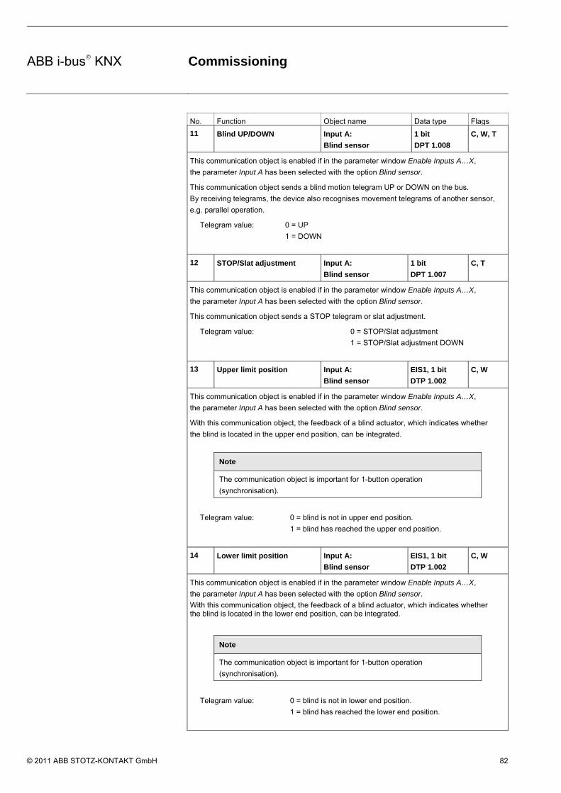
ABB i-bus® KNX Commissioning
© 2011 ABB STOTZ-KONTAKT GmbH 82
No. Function Object name Data type Flags
11 Blind UP/DOWN Input A:
Blind sensor
1 bit
DPT 1.008
C, W, T
This communication object is enabled if in the parameter window Enable Inputs A…X,
the parameter Input A has been selected with the option Blind sensor.
This communication object sends a blind motion telegram UP or DOWN on the bus.
By receiving telegrams, the device also recognises movement telegrams of another sensor,
e.g. parallel operation.
Telegram value: 0 = UP
1 = DOWN
12 STOP/Slat adjustment Input A:
Blind sensor
1 bit
DPT 1.007
C, T
This communication object is enabled if in the parameter window Enable Inputs A…X,
the parameter Input A has been selected with the option Blind sensor.
This communication object sends a STOP telegram or slat adjustment.
Telegram value: 0 = STOP/Slat adjustment
1 = STOP/Slat adjustment DOWN
13 Upper limit position Input A:
Blind sensor
EIS1, 1 bit
DTP 1.002
C, W
This communication object is enabled if in the parameter window Enable Inputs A…X,
the parameter Input A has been selected with the option Blind sensor.
With this communication object, the feedback of a blind actuator, which indicates whether
the blind is located in the upper end position, can be integrated.
Note
The communication object is important for 1-button operation
(synchronisation).
Telegram value: 0 = blind is not in upper end position.
1 = blind has reached the upper end position.
14 Lower limit position Input A:
Blind sensor
EIS1, 1 bit
DTP 1.002
C, W
This communication object is enabled if in the parameter window Enable Inputs A…X,
the parameter Input A has been selected with the option Blind sensor.
With this communication object, the feedback of a blind actuator, which indicates whether the blind is located in the lower end position, can be integrated.
Note
The communication object is important for 1-button operation
(synchronisation).
Telegram value: 0 = blind is not in lower end position.
1 = blind has reached the lower end position.

ABB i-bus® KNX Commissioning
© 2011 ABB STOTZ-KONTAKT GmbH 83
No. Function Object name Data type Flags
15…
19
Not assigned in this operating mode.

ABB i-bus® KNX Commissioning
© 2011 ABB STOTZ-KONTAKT GmbH 84
3.2.11 Operating mode Value/Forced operation
This operating mode allows the sending of values of any data types.
In this chapter, you will find all descriptions for the parameter windows and the corresponding communication objects for operating mode Value/Forced operation.
Note
The inputs B…X do not differ from input A.
The descriptions of the parameter setting possibilities and the adjustable communication objects for the inputs B…X should be taken from the descriptions from parameter window Enable Inputs A…X, page 50!

ABB i-bus® KNX Commissioning
© 2011 ABB STOTZ-KONTAKT GmbH 85
3.2.11.1 Parameter window A: Value/Forced op.
In this parameter window, all settings are undertaken for parameter window A: Value/Forced operation. The explanations also apply for the Inputs B…X.
This parameter window is visible if in parameter window Enable Inputs A…X, page 50, the option Switch/Dim sensor has been selected in parameter Input A.
Enable communication object "Disable" 1 bit
Options: no yes
• yes: The 1 bit Block communication object is enabled. This can be used to block the input.
Note
If the input is disabled and the option yes is selected with parameter Cyclic sending, the last state is still sent regardless of the block.
Using the communication object Block (No. 10), the physical input can be disabled, but internal sending continues, i.e. the input terminals are physically disconnected from the application program.
The communication object Block (No.10) has no influence on manual operation.

ABB i-bus® KNX Commissioning
© 2011 ABB STOTZ-KONTAKT GmbH 86
Capacitive screening
Options: up to 10 nF (standard) up to 20 nF up to 30 nF up to 40 nF
This parameter defines the degree of capacitive screening. Transmission errors can occur on extended cable lengths under certain conditions, e.g. in a 5 x 1.5 mm2 cable, where two conductors are used as a signal line and one conductor is used for switching loads, it may result in mutual interference. If this proves to be the case in an installation, the sensitivity of the input is increased. It should be noted that the signal evaluation also slows down.
Debounce time
Options: 10/20/30/50/70/100/150 ms
Debouncing prevents unwanted multiple operations of the input, e.g. due to bouncing of the contact.
What is the debounce time?
If an edge is detected at an input, the input will react immediately to this edge, e.g. by sending a telegram. At the same time, the duration of the debounce time TD starts. The signal on the input is not evaluated within the debounce time duration.
The following example clarifies this:
After detection of an edge on the input, further edges are ignored for the debounce time TD.

ABB i-bus® KNX Commissioning
© 2011 ABB STOTZ-KONTAKT GmbH 87
Distinction between short and long operation
Options: yes no
Using this parameter, you set if the input differentiates between short and long operation.
• yes: After opening/closing of the contact, first of all it is necessary to ascertain whether a short or long operation has occurred here. Only thereafter will a possible reaction be triggered.
Note
With Distinction between short and long operation, two communication objects are visible for each input. One communication object only transmits during short operation, the other communication object only during a long operation.
The following drawing shows the function in detail:
TL is the time duration, from which a long operation is detected.

ABB i-bus® KNX Commissioning
© 2011 ABB STOTZ-KONTAKT GmbH 88
3.2.11.1.1 Parameter Distinction between short and long operation – no
If the option no is selected with the parameter Distinction between short and long operation, the following parameters in the parameter window A: Value/Forced op., page 84, are visible.
Opening the contacts => Event 0 Closing the contacts => Event 1
<−−− NOTE
Activate minimum signal time
Options: no yes
• yes: The following parameters appear:
On closing the contact in value x 0.1 s [0…65,535]
Options: 1…10…65,535
On opening the contact in value x 0.1 s [0…65,535]
Options: 1…10…65,535

ABB i-bus® KNX Commissioning
© 2011 ABB STOTZ-KONTAKT GmbH 89
What is the minimum signal time?
In contrast to the debounce time, a telegram is only sent, after the minimum signal duration has elapsed.
The individual functions are:
If an edge is detected on the input, the minimum signal duration will commence. No telegram is sent on the bus at this time. The signal on the input is observed within the minimum signal duration. If a further edge appears at the input during the minimum signal duration, it will be interpreted as a new operation, and the minimum signal duration restarts. If no further edges occur after the start of the minimum signal duration, a telegram is sent on the bus, after the minimum signal duration has timed out.
Example: Minimum signal time of the input signal for a detected edge:
In only two cases, no further edge changes occur within the minimum signal duration TM after a change of edge. For this reason, only both of these are detected as valid.
Scan input after download, ETS reset and bus voltage recovery
Options: no yes
• yes: The value of the communication object is scanned after a download, ETS reset and bus voltage recovery.
• no: The value of the communication object is not scanned after a download, ETS reset and bus voltage recovery.
With option yes, the following additional parameters appear in the parameter:

ABB i-bus® KNX Commissioning
© 2011 ABB STOTZ-KONTAKT GmbH 90
Inactive wait state after bus voltage recovery in s [0…30,000]
Options: 0…30,000
Here the waiting time after a bus voltage recovery is set. After the waiting time has elapsed, the state on the input terminals is scanned. The input reacts as if the state on the input terminals has just changed.
Note
The inactive waiting time does not add to the actual, adjustable send delay time. This can be set separately.
Value 1 (Reaction with event 0)
Options: do not send 1 bit value [0/1] 2 bit value [forced operation] 1 byte value [-128…127] 1 byte value [0…255] 1 byte value [8 bit scene] 2 byte value [-32,768…32,767] 2 byte value [0…65,565] 2 byte value [EIB floating point] 3 byte value [time of day, weekday] 4 byte value [-2,147,483,648…2,147,483,647] 4 byte value [0…4,294,967,295]
This parameter serves for defining the data type, which is sent when the contact is actuated.
Depending on the selection made in parameter Value 1 (rising edge / short operation), different parameters appear. All parameters are described in the following:
sent value [X]
Options: ON/OFF/TOGGLE 0/1 -128…0…127 0…255 -32,768…0…32,767 0…65,535 -100…20…100 -2,147,483,648…0…2,147,483,647 0…4,294,967,295
This parameter defines the value, which is sent on actuation. The value range is dependent on the set data type of the value X.

ABB i-bus® KNX Commissioning
© 2011 ABB STOTZ-KONTAKT GmbH 91
sent value
Options: ON, activate forced operation OFF, activate forced operation Disable forced operation
This parameter defines the value, which is sent on actuation.
In the following table, the forced operation function is explained:
Bit 1 Bit 0 Acces Description
0 0 Free
0 1 Free
The switch output is enabled via the communication object
Forced operation of the actuator. In this way, it is possible
to switch the actuator directly via the communication object
Switch.
1 0 Off The switch output is disabled via the communication object
Forced operation of the actuator. Now it is no longer
possible to switch the actuator directly via the
communication object Switch.
1 1 On The switch output is enabled via the communication object
Forced operation of the actuator. Now it is no longer
possible to switch the actuator directly via the
communication object Switch.
8 bit scene
Options: 1…64
This parameter defines the KNX scene number, which is sent on actuation.
Store/Call scene
Options: call save
This parameter defines whether the scene is to be called or saved.
Hour [0…23]
Options: 0…23
Minute [0…59]
Options: 0…59
Seconds [0…59]
Options: 0…59
With these parameters, the hours, minutes and seconds, which are to be sent when actuated are set.

ABB i-bus® KNX Commissioning
© 2011 ABB STOTZ-KONTAKT GmbH 92
Weekday [1 = Mo, 2…6 , 7 = Su]
Options: 0 = no day 1 = Monday 2 = Tuesday 3 = Wednesday 4 = Thursday 5 = Friday 6 = Saturday 7 = Sunday
Using these parameters, the weekday, which is sent on actuation, is set.
Value 2 (Reaction with event 1)
Note
The parameter descriptions of the parameter Value 2 (Reaction with event 1) correspond to those of the parameter Value 1 (Reaction with event 0).

ABB i-bus® KNX Commissioning
© 2011 ABB STOTZ-KONTAKT GmbH 93
3.2.11.1.2 Parameter Distinction between short and long operation – yes
If the option yes is selected with the parameter Distinction between short and long operation, the following parameters appear:
Connected contact type
Options: closed open
closed: The input is closed with actuation.
open: The input is opened with actuation.
Long operation after …
Options: 0.3/0.4/0.5/0.6/0.8 s 1/1.2/1.5 s 2/3/4/5/6/7/8/9/10 s
Here the time period TL, after which an actuation is considered a “long” operation, is defined.
Note
The remaining parameter descriptions can be found in the parameter Distinction between short and long operation – no, page 87.

ABB i-bus® KNX Commissioning
© 2011 ABB STOTZ-KONTAKT GmbH 94
3.2.11.2 Communication objects Value/forced operation
The communication objects of all Inputs do not differentiate from one another and are explained using Input A. The descriptions of the parameter setting options of Inputs A…X are described from parameter window Enable Inputs A…X, page 50.
The communication objects Input A have the nos. 10…19.
The communication objects Input B have the nos. 20…29.
The communication objects Input C have the nos. 30…39.
The communication objects Input D have the nos. 40…49.
The communication objects Input E have the nos. 50…59.
The communication objects Input F have the nos. 60…69.
The communication objects Input G have the nos. 70…79.
The communication objects Input H have the nos. 80…89.
No. Function Object name Data type Flags
10 Block Input A: 1 bit
DPT 1.003
C, W
This communication object is enabled if in parameter window A: Value/Forced operation
the parameter Enable communication object "Disable" 1 bit has been selected with option yes.
Using the communication object Block, the input can be disabled or enabled. With activated
communication object Block, the inputs are disabled.
Note
When the input is disabled, there is fundamentally no reaction to a signal
change, but:
– Waiting for a long button operation or a minimum signal
time is suspended.
– The parameter setting 8 bit scene is ended with saving.
– Communication objects continue to be updated and sent if necessary.
When enabling an input, a change of the signal states (as opposed to before
the block) leads to immediate processing, e.g.:
– The minimum actuation or detection of a long/short button push starts.
– Communication objects send their current value if necessary.
The communication object Block has no influence on manual operation. The
status of the simulated input signal continues to be sent here.
Telegram value: 0 = enable input A
1 = disable input A

ABB i-bus® KNX Commissioning
© 2011 ABB STOTZ-KONTAKT GmbH 95
No. Function Object name Data type Flags
11 Value 1, unsigned Input A:
Value/Forced operation
variable
DPT variable
C, T
This communication object is enabled if in the parameter window Enable Inputs A…X, the
parameter Input A has been selected with the option Value/Forced operation.
This communication object sends a value on the bus with short operation when opening or
closing of the contact. The value and data type can be freely set in the parameters.
1 bit value [0/1]
2 bit value [0…3]
1 byte value [-128…127]
1 byte value [0…255]
1 byte value [8 bit scene]
2 byte value [-32 768 32 767]
DPT 1.001 switch telegram
DPT 2.001 forced operation
DPT 6.010 value
DPT 5.010 value
DPT 18.001 control scene
DPT 7.001 value
2 byte value [0…65.535]
2-byte value [EIB floating point]
3 byte value [time of day, weekday]
4 byte value [0…4,294,967,295]
DPT 8.010 value
DPT 9.001 temperature
DPT 10.001 time of day, weekday
DPT 12.010 value
4 byte value [-2.147.483.648…2.147.483.647] DPT 13.010 value
12 Value 2, unsigned
See communication object 11.
13…
19
Not assigned in this operating mode.

ABB i-bus® KNX Commissioning
© 2011 ABB STOTZ-KONTAKT GmbH 96
3.2.12 Operating mode Control scene
This operating mode enables calling and saving the states of several actuator groups. An actuator group consists of several communication objects that are associated by the same group address. It can, for example, consist of switching actuators (1 bit values) or dimming actuators (1 byte values). The data types can be parameterized.
In this chapter, you will find all descriptions for the parameter windows and the corresponding communication objects for operating mode Control scene.
Note
The inputs B…X do not differ from input A.
The descriptions of the parameter setting possibilities and the adjustable communication objects for the inputs B…X should be taken from the descriptions from parameter window Enable Inputs A…X, page 50!

ABB i-bus® KNX Commissioning
© 2011 ABB STOTZ-KONTAKT GmbH 97
3.2.12.1 Parameter window A: Control scene
In this parameter window, all settings are undertaken for parameter window A: Control scene. The explanations also apply for the Inputs B…X.
This parameter window is visible if in parameter window Enable Inputs A…X, page 50, the option Control scene has been selected in parameter Input A.
Enable communication object "Disable" 1 bit
Options: no yes
• yes: The 1 bit Block communication object is enabled. This can be used to block the input.
Note
If the input is disabled and the option yes is selected with parameter Cyclic sending, the last state is still sent regardless of the block.
Using the communication object Block (No. 10), the physical input can be disabled, but internal sending continues, i.e. the input terminals are physically disconnected from the application program.
The communication object Block (No.10) has no influence on manual operation.

ABB i-bus® KNX Commissioning
© 2011 ABB STOTZ-KONTAKT GmbH 98
Capacitive screening
Options: up to 10 nF (standard) up to 20 nF up to 30 nF up to 40 nF
This parameter defines the degree of capacitive screening. Transmission errors can occur on extended cable lengths under certain conditions, e.g. in a 5 x 1.5 mm2 cable, where two conductors are used as a signal line and one conductor is used for switching loads, it may result in mutual interference. If this proves to be the case in an installation, the sensitivity of the input is increased. It should be noted that the signal evaluation also slows down.
Debounce time
Options: 10/20/30/50/70/100/150 ms
Debouncing prevents unwanted multiple operations of the input, e.g. due to bouncing of the contact.
What is the debounce time?
If an edge is detected at an input, the input will react immediately to this edge, e.g. by sending a telegram. At the same time, the duration of the debounce time TD starts. The signal on the input is not evaluated within the debounce time duration.
Example: Debounce time of the input signal for a detected edge:
After detection of an edge on the input, further edges are ignored for the debounce time TD.
Connected contact type
Options: closed open
• closed: The input is closed with actuation.
• open: The input is opened with actuation.

ABB i-bus® KNX Commissioning
© 2011 ABB STOTZ-KONTAKT GmbH 99
Store scene
Options: no on long operation with object value = 1 on long operation and object value = 1
This parameter determines the way in which saving the current scene is triggered and which function the communication object Store scene has. This is dependent on the control of the scene.
• on long operation: Saving is activated as soon as a long operation has been detected.
• object value = 1: If the communication object Store scene receives the value 1, saving is activated.
• on long operation and object value = 1: Saving is activated as soon as a long operation has been detected and the communication object Enable storing has the value 1.
What happens on the bus when Store scene has been triggered?
The scene is simply adapted by saving the current actuator values.
The communication object Store scene indication sends the value 1 if all feedbacks from the communication objects have been received. (Start of scene saving)
The values of the communication objects concerned are read via the bus.
The communication object Store scene indication sends the value 0, if not all feedbacks from the communication objects have been received should the button be released prematurely. Saving is not undertaken if the button is released prematurely.
If the option on long operation or on long operation and object value = 1 have been selected in the parameter Store scene, the following parameter appears.

ABB i-bus® KNX Commissioning
© 2011 ABB STOTZ-KONTAKT GmbH 100
Long operation after…
Options: 0.3/0.4/0.5/0.6/0.8/1/1.2/1.5/2/3/4/5/6/7/8/9/10 s
Here the time period TL, after which an actuation is considered a “long” operation, is defined.
Actuator group A: type
Options: 1 bit value (ON/OFF) 1 byte value [0…100 %] 1 byte value [0…255] 2 byte value [temperature]
The different data types can be selected for each of the 6 actuator groups A…F.
Note
The setting options of actuator groups B…F do not differentiate from those of actuator group A. For this reason, only actuator group A will be explained here.
Depending on the data type set for the actuator groups, various options will be visible in the following Preset value parameter.
Preset value
Options: ON/OFF 0/10/20/30/40/50/60/70/80/90/100 % 0…255 -100,00…20,00…100,00
This parameter defines the value which is sent on actuation. The value range is dependent on the set data type of the value X.
Note
If a scene has been saved via the bus and the preset value should now be restored, the communication object Restore scene to default must be written with the value 1. This is implemented via a download of the preset values or via an ETS reset.
Store via the bus
Options: yes no
This parameter defines whether the scene is to be saved via the bus. The parameter is only active if the option has not been set to no in the parameter Store scene. If reading of a communication object is not possible, the setting should be left at no (see parameter Store scene), otherwise, it may not be possible to save the entire scene.

ABB i-bus® KNX Commissioning
© 2011 ABB STOTZ-KONTAKT GmbH 101
3.2.12.2 Communication objects Control scene
The communication objects of all Inputs do not differentiate from one another and are explained using Input A. The descriptions of the parameter setting options of Inputs A…X are described from parameter window Enable Inputs A…X, page 50.
The communication objects Input A have the nos. 10…19.
The communication objects Input B have the nos. 20…29.
The communication objects Input C have the nos. 30…39.
The communication objects Input D have the nos. 40…49.
The communication objects Input E have the nos. 50…59.
The communication objects Input F have the nos. 60…69.
The communication objects Input G have the nos. 70…79.
The communication objects Input H have the nos. 80…89.

ABB i-bus® KNX Commissioning
© 2011 ABB STOTZ-KONTAKT GmbH 102
No. Function Object name Data type Flags
10 Block Input A: 1 bit
DPT 1.003
C, W
This communication object is enabled if in parameter window A: Control scene
the parameter Enable communication object "Disable" 1 bit has been selected with option yes.
Using the communication object Block, the input can be disabled or enabled. With activated
communication object Block, the inputs are disabled.
Note
When the input is disabled, there is fundamentally no reaction to a signal
change, but:
– Waiting for a long button operation or a minimum signal
time is suspended.
– The parameter setting 8 bit scene is ended with saving.
– Communication objects continue to be updated and sent if necessary.
When enabling an input, a change of the signal states (as opposed to before
the block) leads to immediate processing, e.g.:
– The minimum actuation or detection of a long/short button push starts.
– Communication objects send their current value if necessary.
The communication object Block has no influence on manual operation. The
status of the simulated input signal continues to be sent here.
Telegram value: 0 = enable input A
1 = disable input A
11 Actuator group
A[variable]
Input A:
Control scene
variable
DPT variable
C, W, T
Depending on the setting, this communication object sends the following values on the bus.
1 bit value (ON/OFF)
1 byte value [0…100]
1 byte value [0…255]
2 byte value [temperature]
DPT 1.001 switch value
DPT 5.001 percentage value
DPT 5.010 counter value
DPT 9.001 temperature
12 Actuator group B[
variable]
Input A:
Control scene
variable
DPT variable
C, W, T
Depending on the setting, this communication object sends the following values on the bus.
1 bit value (ON/OFF)
1 byte value [0…100]
1 byte value [0…255]
2 byte value [temperature]
DPT 1.001 switch value
DPT 5.001 percentage value
DPT 5.010 counter value
DPT 9.001 temperature

ABB i-bus® KNX Commissioning
© 2011 ABB STOTZ-KONTAKT GmbH 103
No. Function Object name Data type Flags
13 Actuator group C
[variable]
Input A:
Control scene
Variable
DPT variable
C, W, T
Depending on the setting, this communication object sends the following values on the bus.
1 bit value (ON/OFF)
1 byte value [0…100]
1 byte value [0…255]
2 byte value [temperature]
DPT 1.001 switch value
DPT 5.001 percentage value
DPT 5.010 counter value
DPT 9.001 temperature
14 Actuator group D
[variable]
Input A:
Control scene
Variable
DPT variable
C, W, T
Depending on the setting, this communication object sends the following values on the bus.
1 bit value (ON/OFF)
1 byte value [0…100]
1 byte value [0…255]
2 byte value [temperature]
DPT 1.001 switch value
DPT 5.001 percentage value
DPT 5.010 counter value
DPT 9.001 temperature
15 Actuator group E
[variable]
Input A:
Control scene
Variable
DPT variable
C, W, T
Depending on the setting, this communication object sends the following values on the bus.
1 bit value (ON/OFF)
1 byte value [0…100]
1 byte value [0…255]
2 byte value [temperature]
DPT 1.001 switch value
DPT 5.001 percentage value
DPT 5.010 counter value
DPT 9.001 temperature
16 Actuator group F
[variable]
Input A:
Control scene
Variable
DPT variable
C, W, T
Depending on the setting, this communication object sends the following values on the bus.
1 bit value (ON/OFF)
1 byte value [0…100]
1 byte value [0…255]
2 byte value [temperature]
DPT 1.001 switch value
DPT 5.001 percentage value
DPT 5.010 counter value
DPT 9.001 temperature
17 Store scene Input A:
Control scene
1 bit
DPT 1.003
C, W
This communication object appears only with the option Object value = 1. This object can be
set in the parameter Store scene. This communication object is used to enable saving of a
scene via the bus. The function depends on the method of storing the scene.

ABB i-bus® KNX Commissioning
© 2011 ABB STOTZ-KONTAKT GmbH 104
No. Function Object name Data type Flags
17 Enable storing Input A:
Control scene
1 bit
DPT 1.003
C, W
This communication object appears only with the option on long operation and object value =
1. This object can be set in the parameter Store scene. This communication object is used to
trigger saving of a scene via the bus. The function depends on the method of storing the
scene.
18 Store scene indication Input A:
Control scene
1 bit
DPT 1.003
C, T
This communication object is used to indicate saving of a scene, e.g. by an LED. The function
depends on the method of storing the scene.
19 Restore scene to
default
Input A:
Control scene
1 bit
DPT 1.003
C, R, W, T
This communication object is used to restore a scene to the default settings.

ABB i-bus® KNX Commissioning
© 2011 ABB STOTZ-KONTAKT GmbH 105
3.2.13 Operating mode Switching sequences
A switching sequence facilitates a step-by-step change of up to five switching objects with just a single input actuation. In this way, up to 5 actuators or actuator groups can be switched in a defined switching sequence.
In this chapter, you will find all descriptions for the parameter windows and the corresponding communication objects for operating mode Switching sequences.
Note
The inputs B…X do not differ from input A.
The descriptions of the parameter setting possibilities and the adjustable communication objects for the inputs B…X should be taken from the descriptions from parameter window Enable Inputs A…X, page 50!

ABB i-bus® KNX Commissioning
© 2011 ABB STOTZ-KONTAKT GmbH 106
3.2.13.1 Parameter window A: Switching sequences
In this parameter window, all settings are undertaken for parameter window A: Switching sequences. The explanations also apply for the Inputs B…X.
This parameter window is visible if in parameter window Enable Inputs A…X, page 50, the option Switching sequences has been selected in parameter Input A.
Enable communication object "Disable" 1 bit
Options: no yes
• yes: The 1 bit Block communication object is enabled. This can be used to block the input.
Note
If the input is disabled and the option yes is selected with parameter Cyclic sending, the last state is still sent regardless of the block.
Using the communication object Block (No. 10), the physical input can be disabled, but internal sending continues, i.e. the input terminals are physically disconnected from the application program.
The communication object Block (No. 10) has no influence on manual operation.

ABB i-bus® KNX Commissioning
© 2011 ABB STOTZ-KONTAKT GmbH 107
Capacitive screening
Options: up to 10 nF (standard) up to 20 nF up to 30 nF up to 40 nF
This parameter defines the degree of capacitive screening. Transmission errors can occur on extended cable lengths under certain conditions, e.g. in a 5 x 1.5 mm2 cable, where two conductors are used as a signal line and one conductor is used for switching loads, it may result in mutual interference. If this proves to be the case in an installation, the sensitivity of the input is increased. It should be noted that the signal evaluation also slows down.
Debounce time
Options: 10/20/30/50/70/100/150 ms
Debouncing prevents unwanted multiple operations of the input, e.g. due to bouncing of the contact.
What is the debounce time?
If an edge is detected at an input, the input will react immediately to this edge, e.g. by sending a telegram. At the same time, the duration of the debounce time TD starts. The signal on the input is not evaluated within the debounce time duration.
The following example clarifies this:
After detection of an edge on the input, further edges are ignored for the debounce time TD.
Connected contact type
Options: closed open
• closed: The input is closed with actuation.
• open: The input is opened with actuation.

ABB i-bus® KNX Commissioning
© 2011 ABB STOTZ-KONTAKT GmbH 108
Activate minimum signal time
Options: no yes
• yes: The following parameters appear:
for rising edge in value x 0.1 s [1…65,535]
Options: 1…10…65,535
Note
A rising edge corresponds to a normally opened contact function.
for falling edge in value x 0.1 s [1…65,535]
Options: 1…10…65,535
Note
A falling edge corresponds to a normally closed contact function.
What is the minimum signal time?
In contrast to the debounce time, a telegram is only sent, after the minimum signal duration has elapsed.
The individual functions are:
If an edge is detected on the input, the minimum signal duration will commence. No telegram is sent on the bus at this time. The signal on the input is observed within the minimum signal duration. If a further edge appears at the input during the minimum signal duration, it will be interpreted as a new operation, and the minimum signal duration restarts. If no further edges occur after the start of the minimum signal duration, a telegram is sent on the bus, after the minimum signal duration has timed out.
Example: Minimum signal time of the input signal for a detected edge:
In only two cases, no further edge changes occur within the minimum signal duration TM after a change of edge. For this reason, only both of these are detected as valid.

ABB i-bus® KNX Commissioning
© 2011 ABB STOTZ-KONTAKT GmbH 109
Number of levels:
Options: 2/3/4/5
The number of levels (maximum 5) corresponds to the number of communication objects: The communication objects Value 1 to Value 5 are enabled accordingly.
Type of switching sequence (example: 3 levels)
Options: =>000-001-011-111 (sequence 1) Gray code (sequence 2) <=000-001-011-111-011-001=> (sequence 3) <=000-001-011-111=> (sequence 4) <=000-001-000-010-000-100=> (sequence 5)
The switching sequences correspond to the states of three communication objects (0 = OFF, 1 = ON).
The type of switching sequences can be chosen here. Each sequence has different communication objects for each level.
The switching sequences allow switch on or off of up to five communication objects (1 bit) in a defined sequence. Every time the button is switched, one further step in the sequence occurs.
Switching sequences <=000-001-011-111=> (sequence 1)
With this switching sequence, a further group address is sent via another communication object (value x) after each successive actuation. If all group addresses have been sent in one direction via the communication objects (value x), further actuations are ignored. For this reason, at least two binary inputs are required, where one switches upwards and the other switches downwards.
Note
The group addresses must be different for separate upward and downward switching.
A synchronization for the switching sequences for up and down is implemented using the number of the switching sequence operation. The same group address must be used here.
Value of the communication objects Number of operation Switching sequence
Switch 3 Switch 2 Switch 1
0 000 OFF OFF OFF
1 001 OFF OFF ON
2 011 OFF ON ON
3 111 ON ON ON
… … … … …

ABB i-bus® KNX Commissioning
© 2011 ABB STOTZ-KONTAKT GmbH 110
Gray code (sequence 2)
In this sequence, all communication object combinations are undertaken successively. Only the value of one communication object changes between two switching levels. A good example of this switching sequence, for example, is switching of two lighting groups in the sequence 00 – 01 – 11 – 10 – 00 ...
For further information see: Gray code, page 151
Switching sequence <=000-001-011-111-011-001=> (sequence 3)
This switching sequence switches on a further communication object with each successive actuation. If all communication objects are switched on, they are switched off successively commencing with the last one to be switched on.
Value of the communication objects Number of operation Switching sequence
Switch 3 Switch 2 Switch 1
0 000 OFF OFF OFF
1 001 OFF OFF ON
2 011 OFF ON ON
3 111 ON ON ON
4 011 OFF ON ON
5 001 OFF OFF ON
… … … … …
Switch sequence <=000-001-011-111-000=> (sequence 4)
This switching sequence switches on a further communication object with each successive actuation. If all communication objects are switched on, they are all switch off together.
Value of the communication objects Number of operation Switching sequence
Switch 3 Switch 2 Switch 1
0 000 OFF OFF OFF
1 001 OFF OFF ON
2 011 OFF ON ON
3 111 ON ON ON
… … … … …

ABB i-bus® KNX Commissioning
© 2011 ABB STOTZ-KONTAKT GmbH 111
Switch sequence <=000-001-010-000-100-000=> (sequence 5)
This switching sequence switches on with the actuation of a communication object and then off again. Thereafter, other communication objects are switched on or off.
Value of the communication objects Number of operation Switching sequence
Switch 3 Switch 2 Switch 1
0 000 OFF OFF OFF
1 001 OFF OFF ON
2 011 OFF OFF OFF
3 111 OFF ON OFF
4 011 OFF OFF OFF
5 001 ON OFF OFF
… … … … …
Further possibilities
In addition to actuation of the binary input, the switching sequence can be changed by using communication object Level increment/decrement.
This is used, for example, to switch two or more binary inputs upwards and/or downwards.
Note
The current switching sequence results from the value of the Number of operation of the switching sequences.
Direction on operation
Options: upwards downwards
This parameter determines, whether the level is switched upwards or downwards, when the button is pushed.

ABB i-bus® KNX Commissioning
© 2011 ABB STOTZ-KONTAKT GmbH 112
3.2.13.2 Communication objects Switch sequences
The communication objects of all Inputs do not differentiate from one another and are explained using Input A. The descriptions of the parameter setting options of Inputs A…X are described from parameter window Enable Inputs A…X, page 50.
The communication objects Input A have the nos. 10…19.
The communication objects Input B have the nos. 20…29.
The communication objects Input C have the nos. 30…39.
The communication objects Input D have the nos. 40…49.
The communication objects Input E have the nos. 50…59.
The communication objects Input F have the nos. 60…69.
The communication objects Input G have the nos. 70…79.
The communication objects Input H have the nos. 80…89.

ABB i-bus® KNX Commissioning
© 2011 ABB STOTZ-KONTAKT GmbH 113
No. Function Object name Data type Flags
10 Block Input A: 1 bit
DPT 1.003
C, W
This communication object is enabled if in parameter window A: Switching sequences
the parameter Enable communication object "Disable" 1 bit has been selected with option yes.
Using the communication object Block, the input can be disabled or enabled. With activated
communication object Block, the inputs are disabled.
Note
When the input is disabled, there is fundamentally no reaction to a signal
change, but:
– Waiting for a long button operation or a minimum signal
time is suspended.
– The parameter setting 8 bit scene is ended with saving.
– Communication objects continue to be updated and sent if necessary.
When enabling an input, a change of the signal states (as opposed to before
the block) leads to immediate processing, e.g.:
– The minimum actuation or detection of a long/short button push starts.
– Communication objects send their current value if necessary.
The communication object Block has no influence on manual operation. The
status of the simulated input signal continues to be sent here.
Telegram value: 0 = enable input A
1 = disable input A
11 Value 1 Input A:
Switching
1 bit
DPT 1.001
C, W, T
The number of these maximum of 5 communication objects is set in parameter Number of
levels. The communication objects represent the values within the switching sequence.
12 Value 2 Input A:
Switching
sequences
1 bit
DPT 1.001
C, W, T
The number of these maximum of 5 communication objects is set in parameter Number of
levels. The communication objects represent the values within the switching sequence.
13 Value 3 Input A:
Switching
sequences
1 bit
DPT 1.001
C, W, T
The number of these maximum of 5 communication objects is set in parameter Number of
levels. The communication objects represent the values within the switching sequence.
14 Value 4 Input A:
Switching
sequences
1 bit
DPT 1.001
C, W, T
The number of these maximum of 5 communication objects is set in parameter Number of
levels. The communication objects represent the values within the switching sequence.

ABB i-bus® KNX Commissioning
© 2011 ABB STOTZ-KONTAKT GmbH 114
No. Function Object name Data type Flags
15 Value 5 Input A:
Switching
sequences
1 bit
DPT 1.001
C, W, T
The number of these maximum of 5 communication objects is set in parameter Number of
levels. The communication objects represent the values within the switching sequence.
16 Level increment/decrement Input A:
Switching
sequences
1 bit
DPT 1.001
C, W
Telegram value: 0 = switch level downwards
1 = switch level upwards
When a telegram is received with the value 1 on the communication object, the input of a stage
in the switching sequence switches up. If a telegram with the value 0 is received, it switches
down.
17 Number of operation Input A:
Switching
sequences
1 byte
DPT 5.010
C, W, T
This communication object includes the number of operation of the respective switching sequence. With synchronization of several binary inputs, the respective communication object should be linked with the same group address.
Note
Ensure that the number of communication objects is equal to the inputs to be
synchronised, e.g. 3 stages.
18…
19
Not assigned in this operating mode.

ABB i-bus® KNX Commissioning
© 2011 ABB STOTZ-KONTAKT GmbH 115
3.2.14 Operating mode Multiple operation
This operating mode ensures that the number of actuations assigned to a communication object value is set and sent via an assigned group address in dependence on the number of button operations. In this way, it is possible, e.g. that different light scenes can be implemented depending on the number of multiple operations.
In this chapter, you will find all descriptions for the parameter windows and the corresponding communication objects for operating mode Multiple operation.
Note
The inputs B…X do not differ from input A.
The descriptions of the parameter setting possibilities and the adjustable communication objects for the inputs B…X should be taken from the descriptions from parameter window Enable Inputs A…X, page 50!

ABB i-bus® KNX Commissioning
© 2011 ABB STOTZ-KONTAKT GmbH 116
3.2.14.1 Parameter window A: Multiple operation
In this parameter window, all settings are undertaken for parameter window A: Switching sequences. The explanations also apply for the Inputs B…X.
This parameter window is visible if in parameter window Enable Inputs A…X, page 50, the option Switching sequences has been selected in parameter Input A.
Enable communication object "Disable" 1 bit
Options: no yes
• yes: The 1 bit Block communication object is enabled. This can be used to block the input.
Note
If the input is disabled and the option yes is selected with parameter Cyclic sending, the last state is still sent regardless of the block.
Using the communication object Block (No. 10), the physical input can be disabled, but internal sending continues, i.e. the input terminals are physically disconnected from the application program.
The communication object Block (No.10) has no influence on manual operation.

ABB i-bus® KNX Commissioning
© 2011 ABB STOTZ-KONTAKT GmbH 117
Capacitive screening
Options: up to 10 nF (standard) up to 20 nF up to 30 nF up to 40 nF
This parameter defines the degree of capacitive screening. Transmission errors can occur on extended cable lengths under certain conditions, e.g. in a 5 x 1.5 mm2 cable, where two conductors are used as a signal line and one conductor is used for switching loads, it may result in mutual interference. If this proves to be the case in an installation, the sensitivity of the input is increased. It should be noted that the signal evaluation also slows down.
Debounce time
Options: 10/20/30/50/70/100/150 ms
Debouncing prevents unwanted multiple operations of the input, e.g. due to bouncing of the contact.
What is the debounce time?
If an edge is detected at an input, the input will react immediately to this edge, e.g. by sending a telegram. At the same time, the duration of the debounce time TD starts. The signal on the input is not evaluated within the debounce time duration.
The following example clarifies this:
After detection of an edge on the input, further edges are ignored for the debounce time TD.
Connected contact type
Options: closed open
• closed: The input is closed with actuation.
• open: The input is opened with actuation.

ABB i-bus® KNX Commissioning
© 2011 ABB STOTZ-KONTAKT GmbH 118
Additional communication object for long operation
Options: yes no
A further function can be carried out with long operation of the input via the communication object Long operation. If a long operation is undertaken within the maximum time after one or more short operations, the short operations are ignored.
• yes: The communication object Long operation is enabled. An additional parameter appears:
Long operation after …
Options: 0.3/0.4/0.5/0.6/0.8 s 1/1.2/1.5 s 2/3/4/5/6/7/8/9/10 s
Here the time period TL, after which an actuation is considered a “long” operation, is defined.
Max. number of operations ( = number of communication objects)
Options: 1-fold 2-fold 3-fold 4-fold
This parameter defines the maximum number of operations that are possible. The number is equal to the number of communication objects x-fold operation. If the button is actuated more often, the maximum value set here, the binary input responds in accordance with the set maximum value.
sent value (object "...-fold operation"
Options: ON OFF TOGGLE
This parameter defines the value of the communication object that should be sent. The settings ON, OFF and TOGGLE are possible. The current value of the communication object is inverted using TOGGLE.

ABB i-bus® KNX Commissioning
© 2011 ABB STOTZ-KONTAKT GmbH 119
Send value on every operation
Options: yes no
• yes: The respective value of the communication object is updated and sent with each actuation.
Example
With three button actuations, the communication objects 1-fold operation (after the 1st operation), 2-fold operation (after the 2nd operation) and 3-fold operation (after the 3rd operation) are sent successively immediately after the respective operation.
• no: The physical input counts the number of operations that occur successively within the allowed time interval. Thereafter, the corresponding number of communication objects, e.g.: three counted operations = CO 3-fold operation is sent.
Maximum time between two operations
Options: 0.3/0.4/0.5/0.6/0.8/1/1.2/1.5/2/3/4/5/6/7/8/9/10 s
This parameter determines the time that can elapse between two operations. After an operation, it will wait for the time entered here. If there are no further operations within this period, the communication object x-fold operation is sent. With a further operation, the time set here restarts.
If in parameter Additional communication object for long operation the option yes is selected, the following parameter appears:
sent value (object "Telegr. operation long")
Options: ON OFF TOGGLE
A further function can be carried out with long operation of the button via the communication object Long operation. If a long operation of the button is undertaken within the maximum time after one or more short operations, the short operations are ignored.

ABB i-bus® KNX Commissioning
© 2011 ABB STOTZ-KONTAKT GmbH 120
3.2.14.2 Communication objects Multiple operation
The communication objects of all Inputs do not differentiate from one another and are explained using Input A. The descriptions of the parameter setting options of Inputs A…X are described from parameter window Enable Inputs A…X, page 50.
The communication objects Input A have the nos. 10…19.
The communication objects Input B have the nos. 20…29.
The communication objects Input C have the nos. 30…39.
The communication objects Input D have the nos. 40…49.
The communication objects Input E have the nos. 50…59.
The communication objects Input F have the nos. 60…69.
The communication objects Input G have the nos. 70…79.
The communication objects Input H have the nos. 80…89.

ABB i-bus® KNX Commissioning
© 2011 ABB STOTZ-KONTAKT GmbH 121
No. Function Object name Data type Flags
10 Block Input A: 1 bit
DPT 1.003
C, W
This communication object is enabled if in parameter window A: Multiple operation,
the parameter Enable communication object "Disable" 1 bit has been selected with option yes.
Using the communication object Block, the input can be disabled or enabled. With activated
communication object Block, the inputs are disabled.
Note
When the input is disabled, there is fundamentally no reaction to a signal
change, but:
– Waiting for a long button operation or a minimum signal
time is suspended.
– The parameter setting 8 bit scene is ended with saving.
– Communication objects continue to be updated and sent if necessary.
When enabling an input, a change of the signal states (as opposed to before
the block) leads to immediate processing, e.g.:
– The minimum actuation or detection of a long/short button push starts.
– Communication objects send their current value if necessary.
The communication object Block has no influence on manual operation. The
status of the simulated input signal continues to be sent here.
Telegram value: 0 = enable input A
1 = disable input A
11 1-fold operation Input A:
Multiple operation
1 bit
DPT 1.001
C, W, T
After multiple operations of an input, the respective communication object is sent to suit the
number of operations.
The telegram value can be set in the parameters.
12 2-fold operation Input A:
Multiple operation
1 bit
DPT 1.001
C, W, T
After multiple operations of an input, the respective communication object is sent to suit the
number of operations.
The telegram value can be set in the parameters.
13 3-fold operation Input A:
Multiple operation
1 bit
DPT 1.001
C, W, T
After multiple operations of an input, the respective communication object is sent to suit the
number of operations.
The telegram value can be set in the parameters.

ABB i-bus® KNX Commissioning
© 2011 ABB STOTZ-KONTAKT GmbH 122
No. Function Object name Data type Flags
14 4-fold operation Input A:
Multiple operation
1 bit
DPT 1.001
C, W, T
After multiple operations of an input, the respective communication object is sent to suit the
number of operations.
The telegram value can be set in the parameters.
15 Long operation Input A:
Multiple operation
1 bit
DPT 1.001
C, W, T
This communication object is visible if the parameter Additional communication object for long
operation has been set to the value yes. The communication object is sent after a long operation
has been detected. The interval after which an operation is interpreted as “long” can be set.
16…
19
Not assigned in this operating mode.

ABB i-bus® KNX Commissioning
© 2011 ABB STOTZ-KONTAKT GmbH 123
3.2.15 Operating mode Counter
In the operating mode Counter, the device is able to count the number of edges received on the binary input. If required, a differential counter is provided in addition to the normal counter. Both are controlled via the same counting pulses, but count independently of one another.
In this chapter, you will find all descriptions for the parameter windows and the corresponding communication objects for operating mode Counter.
Note
The inputs B…X do not differ from input A.
The descriptions of the parameter setting possibilities and the adjustable communication objects for the inputs B…X should be taken from the descriptions from parameter window Enable Inputs A…X, page 50!
3.2.15.1 Counting pulses The Counter function is used for counting input pulses. In the parameter window Counter a main counter is provided. It is possible to enable a differential counter (comparable with an odometer counting daily mileage) to record differential values. The starting point of the differential counter is programmable. The settings for the differential counter can be found in the additional parameter window A: Differential Counter.
The following illustration provides an overview of the Counter function.
Which preconditions must be fulfilled on the main counter to set the value?
1. Set the write flag.
2. Thereafter, it is possible to set the value via KNX.
Input pulse
Set value
RegisterMain counter
RegisterDifferential counter
ResetFactor/ divider
Send– cyclically– on request
KNX

ABB i-bus® KNX Commissioning
© 2011 ABB STOTZ-KONTAKT GmbH 124
In order to adapt the counter speed, the number of input pulses per counting pulse can be set. Furthermore, a counter level change can be set for each counting pulse. Both counter values can either be sent on the bus cyclically or on request.
Limit values can be defined for the counter. Telegrams are sent after the limit values are exceeded.
Note
The maximum counter frequency may not exceed 5 Hz.
The minimum pulse duration is 50 ms. The maximum capacitive load on the input is 22 nF.
3.2.15.2 Behaviour of the counter readings after a download
The counter readings are not deleted after a download.
3.2.15.3 Behaviour of the counter readings bus voltage failure
The counter readings are saved after a bus voltage failure. The counter readings can be sent after bus voltage recovery.

ABB i-bus® KNX Commissioning
© 2011 ABB STOTZ-KONTAKT GmbH 125
3.2.15.4 Specific feature differences between main counter and differential counter
Description Main Counter Differential
counter
Block yes yes
Data type can defined yes yes
Start value is the smallest limit value when counting
upwards
yes yes
Start value is the largest limit value when counting
downwards
yes yes
The communication object XZ: Limit value reached
sends a 1 as soon as the counter pulse has exceeded
the smaller or larger limit value.
yes yes
If the option continue circular counting is set, the counter
reading is set to the start value and any possible
overflow is added to the start value.
Cannot be set yes
If the option stop until ETS reset is set, this and all
following counter pulses are ignored until the differential
counter is reset by the communication object DC: reset.
Cannot be set yes
Counts up/down adjustable adjustable
Limit value 1 preset to zero yes adjustable
Circular count yes adjustable
Reset the counter no yes

ABB i-bus® KNX Commissioning
© 2011 ABB STOTZ-KONTAKT GmbH 126
3.2.15.5 Parameter window A: Counter
In this parameter window, all settings are undertaken for parameter window A: Counter. The explanations also apply for the Inputs B…X.
This parameter window is visible if in parameter window Enable Inputs A…X, page 50, the option Counter has been selected in parameter Input A.
Enable communication object "Disable" 1 bit
Options: no yes
• yes: The 1 bit Block communication object is enabled. This can be used to block the input.
Note
If the input is disabled and the option yes is selected with parameter Cyclic sending, the last state is still sent regardless of the block.
Using the communication object Block (No. 10), the physical input can be disabled, but internal sending continues, i.e. the input terminals are physically disconnected from the application program.
If the input is disabled, the main counter and the differential counter will not count pulses.
The communication object Block (No. 10) has no influence on manual operation.

ABB i-bus® KNX Commissioning
© 2011 ABB STOTZ-KONTAKT GmbH 127
Capacitive screening
Options: up to 10 nF (standard) up to 20 nF up to 30 nF up to 40 nF
This parameter defines the degree of capacitive screening. Transmission errors can occur on extended cable lengths under certain conditions, e.g. in a 5 x 1.5 mm2 cable, where two conductors are used as a signal line and one conductor is used for switching loads, it may result in mutual interference. If this proves to be the case in an installation, the sensitivity of the input is increased. It should be noted that the signal evaluation also slows down.
Debounce time
Options: 10/20/30/50/70/100/150 ms
Debouncing prevents unwanted multiple operations of the input, e.g. due to bouncing of the contact.
What is the debounce time?
If an edge is detected at an input, the input will react immediately to this edge, e.g. by sending a telegram. At the same time, the duration of the debounce time TD starts. The signal on the input is not evaluated within the debounce time duration.
The following example clarifies this:
After detection of an edge on the input, further edges are ignored for the debounce time TD.
Enable differential Counter
Options: yes
no
• yes: The parameter window Differential counter is enabled.

ABB i-bus® KNX Commissioning
© 2011 ABB STOTZ-KONTAKT GmbH 128
Activate minimum signal time
Options: no yes
• yes: The following parameters appear:
for rising edge in value x 0.1 s [1…65,535]
Options: 1…10…65,535
Note
A rising edge corresponds to a normally opened contact function.
for falling edge in value x 0.1 s [1…65,535]
Options: 1…10…65,535
Note
A falling edge corresponds to a normally closed contact function.
What is the minimum signal time?
In contrast to the debounce time, a telegram is only sent, after the minimum signal duration has elapsed.
The individual functions are:
If an edge is detected on the input, the minimum signal duration will commence. No telegram is sent on the bus at this time. The signal on the input is observed within the minimum signal duration. If a further edge appears at the input during the minimum signal duration, it will be interpreted as a new operation, and the minimum signal duration restarts. If no further edges occur after the start of the minimum signal duration, a telegram is sent on the bus, after the minimum signal duration has timed out.
Example: Minimum signal time of the input signal for a detected edge:
In only two cases, no further edge changes occur within the minimum signal duration TM after a change of edge. For this reason, only both of these are detected as valid.

ABB i-bus® KNX Commissioning
© 2011 ABB STOTZ-KONTAKT GmbH 129
Main Counter
<−−− NOTE
Data type
Options: 8 bit value [-128…127] 8 bit value [0…255] 16 bit value [-32,768…32,767] 16 bit value [0…65,535] 32 bit value [-2,147,485,648…2,147,483,647]
This parameter defines the data type of the counter.
This parameter defines the data type of the differential counter.
Both of the following parameters are dependent on the parameter Data type. Depending on the Data type selected, different limit values are preset. The input fields can be freely edited.
Note
The first reset counter pulse that exceeds or falls below the limit value sets the counter to the opposite limit value. With the next counter pulse, the new counter reading (set according to the respective counter value) continues to count in the parameterized counting direction.
Example
Mode of main counter counting
Limit value 1 [0] of the limit value is set to zero.
Limit value 2 [255] of the limit value is set, for example to 10
For each counter pulse 1 is added commencing at 0.
0=>1=>2=>3=>4=>5=>6=>7=>8=>9=>10 with 10 counter pulses (=>) the upper limit is reached. With the next counter pulse, the counter is set to the opposite limit value, i.e. to 0, and then continues again up to 10. In order to implement a circular count, 11 counter pulses are required here.
Note
It is necessary to ensure that both limit values are set to different values. If the same limit values are defined, the behaviour of the counter is undefined.
The limit values can be set to any value, i.e. limit value 1 can be greater than or less than limit value 2. The application program automatically chooses, for example, the largest limit value from both set limits and starts counting upwards or downwards to suit the direction of counting.

ABB i-bus® KNX Commissioning
© 2011 ABB STOTZ-KONTAKT GmbH 130
Limit value 1 [0]
Limit value 1 is preset to 0 for every data type.
Limit value 2 [X]
Options: 127 [-128…127] 255 [0…255] 32,767 [-32,768…32,767] 65,565 [0…65,535] 2,147,400,000 [-2,147,400,000…2,147,400,000]
Mode of counting
Options: +1 on rising edge (standard) adapt…:
This parameter defines the mode of counting of the counter.
• +1 on rising edge (standard): The counter value is incremented by one with every rising edge.
• adapt…: Three further parameters appear:
Create input pulse
Options: only on rising edge: only on falling edge: on both edges:
With this parameter, you set how the input pulse is to be generated.
• only on rising edge: The pulse is generated with a rising edge.
• only on falling edge: The pulse is generated with a falling edge.
• on both edges: The pulse is generated with a rising and falling edge.
Number of input pulses for one counter step [1...10,000]
Options: 1…10,000
This parameter defines the number of input pulses required to generate a counter pulse for the main and differential counter.
Example
After every 10 input pulses the counters are incremented by 1.

ABB i-bus® KNX Commissioning
© 2011 ABB STOTZ-KONTAKT GmbH 131
Change of counter for every counter step [-10,000...10,000]
Options: -10,000…1…10,000
This parameter defines by how much the counter is changed for a counter pulse.
Negative values, e.g. -1, define the downward counter direction, e.g. 200…0.
Positive values, e.g. 10, define the upward counter direction, e.g. 10…200.
Send counter value on download, ETS reset and bus voltage recovery
Options: yes no
• yes: After bus voltage recovery and after the send delay time has timed out, the device sends the communication object Counter value on the bus.
Send counter values on change
Options: yes no
This parameter defines whether a change of the counter value is to be sent.
Send counter level cyclically
Options: yes no
Using this parameter, you determine if the counter value is sent cyclically on the bus.

ABB i-bus® KNX Commissioning
© 2011 ABB STOTZ-KONTAKT GmbH 132
3.2.15.6 Parameter window A: Differential counter
In this parameter window, all settings are undertaken for parameter window A: Differential Counter. The explanations also apply for the Inputs B…X.
This parameter window is visible if in parameter window Enable Inputs A…X, page 50, the option Counter in parameter Input A and in parameter window A: Counter, page 126, the option yes has been selected in parameter Enable differential Counter.
Data type
Options: 8 bit value [-128…127]/ 8 bit value [0…255]/ 16 bit value [-32,768…32,767]/ 16 bit value [0…65,535] 32 bit value [-2,147,485,648…2,147,483,647]
This parameter defines the data type of the differential counter.
Both of the following parameters are dependent on the parameter Data type. Depending on the Data type selected, different limit values are preset. The input fields can be freely edited.
Note
The first reset counter pulse that exceeds or falls below the limit value sets the counter to the opposite limit value. With the next counter pulse, the new counter reading (set according to the respective counter value) continues to count in the parameterized counting direction.

ABB i-bus® KNX Commissioning
© 2011 ABB STOTZ-KONTAKT GmbH 133
Example
Mode of main counter counting
Limit value 1 [0] of the limit value is set to zero.
Limit value 2 [255] of the limit value is set, for example to 10
For each counter pulse 1 is added commencing at 0.
0=>1=>2=>3=>4=>5=>6=>7=>8=>9=>10 with 10 counter pulses (=>) the upper limit is reached. With the next counter pulse, the counter is set to the opposite limit value, i.e. to 0, and then continues again up to 10. In order to implement a circular count, 11 counter pulses are required here.
Note
It is necessary to ensure that both limit values are set to different values. If the same limit values are defined, the behaviour of the counter is undefined.
The limit values can be set to any value, i.e. limit value 1 can be greater than or less than limit value 2. The application program automatically chooses, for example, the largest limit value from both set limits and starts counting upwards or downwards to suit the direction of counting.
Limit value 1 [X]
Options: 0 [-128…127] 0 [0…255] 0 [-32,768…32,767] 0 [0…65.535] 0 [-2,147,400,000…2,147,400,000]
Limit value 2 [X]
Options: 127 [-128…127] 255 [0…255] 32,767 [-32,768…32,767] 65,565 [0…65,535] 2,147,400,000 [-2,147,400,000…2,147,400,000]

ABB i-bus® KNX Commissioning
© 2011 ABB STOTZ-KONTAKT GmbH 134
Behaviour on crossing the limit value
Options: continue circular counting stop until ETS reset
This parameter defines the reaction to reaching a limit value.
• continue circular counting: The counter continues with circular counting. When the counter drops below the lower limit value (only possible with a downward counter), the counter is set to the value of the larger limit value and the downward pulse count continues from this value. When the larger limit value is exceeded, the counter is set to the lower limit value and pulse counting continues.
• stop until ETS reset: The counter stops and waits for an ETS reset.
Note
After an ETS reset, circular counting continues.
Mode of counting like main counter
<--- Note
The direction of counting of the differential counter is the same as for the main counter.
Reverse direction of counting
Options: yes no
This parameter is used for reversing the direction of counting of the differential counter in comparison to the main counter.
Send counter value on download, ETS reset and bus voltage recovery
Options: yes no
• yes: After bus voltage recovery and after the send delay time has timed out, the device sends the communication object DC: counter value on the bus.
Send counter values on change
Options: yes no
This parameter defines whether a change of the counter value is to be sent.
Send counter level cyclically
Options: yes no
Using this parameter, you set if the counter value is sent cyclically on the bus.

ABB i-bus® KNX Commissioning
© 2011 ABB STOTZ-KONTAKT GmbH 135
3.2.15.7 Communication objects A: Counter
The communication objects of all Inputs do not differentiate from one another and are explained using Input A. The descriptions of the parameter setting options of Inputs A…X are described from parameter window Enable Inputs A…X, page 50.
The communication objects Input A have the nos. 10…19.
The communication objects Input B have the nos. 20…29.
The communication objects Input C have the nos. 30…39.
The communication objects Input D have the nos. 40…49.
The communication objects Input E have the nos. 50…59.
The communication objects Input F have the nos. 60…69.
The communication objects Input G have the nos. 70…79.
The communication objects Input H have the nos. 80…89.

ABB i-bus® KNX Commissioning
© 2011 ABB STOTZ-KONTAKT GmbH 136
No. Function Object name Data type Flags
10 Block Input A: 1 bit
DPT 1.003
C, W
This communication object is enabled if in parameter window A: Counter
the parameter Enable communication object "Disable" 1 bit has been selected with option yes.
Using the communication object Block, the input can be disabled or enabled. With activated
communication object Block, the inputs are disabled.
Note
When the input is disabled, there is fundamentally no reaction to a signal
change, but:
– Waiting for a long button operation or a minimum signal
time is suspended.
– The parameter setting 8 bit scene is ended with saving.
– Communication objects continue to be updated and sent if necessary.
When enabling an input, a change of the signal states (as opposed to before
the block) leads to immediate processing, e.g.:
– The minimum actuation or detection of a long/short button push starts.
– Communication objects send their current value if necessary.
The communication object Block has no influence on manual operation. The
status of the simulated input signal continues to be sent here.
Telegram value: 0 = enable input A
1 = disable input A
11 MC: counter value Input A:
Counter
Variable
DPT variable
C, T
The counter reading of the main counter (MC) can be read out using this communication object.
1 byte value [0…255]
1 byte value [-128…+127]
2 byte value [0…+65,535]
2 byte value [-32,768…+32,767]
4 byte value [-2,147,483,648…2,147,483,647]
DPT 5.010 counter value
DPT 6.010 counter value
DPT 8.001 counter value
DPT 7.001 counter value
DPT 13.001 counter value

ABB i-bus® KNX Commissioning
© 2011 ABB STOTZ-KONTAKT GmbH 137
No. Function Object name Data type Flags
12 DC: counter value Input A:
Counter
Variable
DPT variable
C, T
This communication object is enabled if in parameter window A: Counter
the parameter Enable differential Counter has been selected with option yes.
The counter reading of the main counter (MC) can be read out using this communication object.
1 byte value [0…255]
1 byte value [-128…+127]
2 byte value [0…+65,.535]
2 byte value [-32,768…+32,767]
4 byte value [-2,147,483,648…2,147,483,647]
DPT 5.010 counter value
DPT 6.010 counter value
DPT 8.001 counter value
DPT 7.001 counter value
DPT 13.001 counter value
13 Request counter value Input A:
Counter
1 bit
DPT 1.003
C, W
The counter reading can be modified using this communication object.
Telegram value: 0 = do not request counter value
1 = request counter value
14 MC: limit value
exceeded
Input A:
Counter
1 bit
DPT 1.002
C, T
With this communication object you can indicate if a limit value of the main counter (MC) has
been exceeded.
Telegram value: 1 = limit value exceeded
15 DC: limit value
exceeded
Input A:
Counter
1 bit
DPT 1.002
C, T
This communication object is enabled if in parameter window A: Counter
the parameter Enable differential counter has been selected with the option yes.
With this communication object you can indicate if a limit value of the differential counter (DC)
has been exceeded.
Telegram value: 1 = limit value exceeded
16 DC: reverse direction Input A:
Counter
1 bit
DPT 1.002
C, R, W, T
This communication object is enabled if in parameter window A: Counter
the parameter Enable differential Counter has been selected with option yes.
The counting direction of the differential counter (DC) can changed via the bus using this
communication object.
Telegram value: 0 = count direction as parameterized
1 = count direction counter to parameterization

ABB i-bus® KNX Commissioning
© 2011 ABB STOTZ-KONTAKT GmbH 138
No. Function Object name Data type Flags
17 DC: reset Input A:
Counter
1 bit
DPT 1.002
C, R, W, T
This communication object is enabled if in parameter window A: Counter
the parameter Enable differential Counter has been selected with option yes.
The differential counter (DC) can be reset to the start value using this communication object.
Telegram value: 0 = do not reset differential counter value
1 = reset differential counter value
18 DC: stop Input A:
Counter
1 bit
DPT 1.002
C, R, W, T
This communication object is enabled if in parameter window A: Counter
the parameter Enable differential Counter has been selected with option yes.
The differential counter (DC) can be stopped using this communication object.
Telegram value: 0 = do not stop differential counter value
1 = stop differential counter value
19
Not assigned in this operating mode.

ABB i-bus® KNX Planning and application
© 2011 ABB STOTZ-KONTAKT GmbH 139
4 Planning and application
In this chapter, you will find descriptions relating to the special characteristics of the switch sensor and blind sensor operating modes.
4.1 Block diagram Switch sensor
This block diagram shows the internal structure of the switch sensor.
Physical input
CO14
CO10
Event 0/1 started
BlockCO13
CO12
CO11
Parameters, Logic Switch 1 (cyclic)
Switch 2
Switch 3
Black = direct connectionCO = communication object
Binary Input A: Input Module
Binary Input BE/S

ABB i-bus® KNX Planning and application
© 2011 ABB STOTZ-KONTAKT GmbH 140
4.2 Block diagram Switch/Dim sensor
This block diagram shows the internal structure of the switch/dim sensor.
Physical input
CO10
Block
CO12
CO11
Parameters, Logic Switching
Dimming
Black = direct connectionCO = communication object
Binary Input A: Input Module
Binary Input BE/S

ABB i-bus® KNX Planning and application
© 2011 ABB STOTZ-KONTAKT GmbH 141
4.3 Block diagram Blind sensor
This block diagram shows the internal structure of the blind sensor.
Physical input
CO10
Block
CO12
CO11
Parameters, Logic
Black = direct connectionCO = communication object
Binary Input A: Input Module
Binary Input BE/S
Blind UP/DOWN
STOP/Slat adjustment
CO14
CO13
Upper limit position
Lower limit position

ABB i-bus® KNX Planning and application
© 2011 ABB STOTZ-KONTAKT GmbH 142
4.3.1 Block diagram Blind sensor with external Blind actuator
This block diagram shows the internal structure of the blind sensor with an external blind actuator.
Parameterization of the binary input x:
2 push button operation
Short operation = STOP/Slat UP Long operation = Move UP
Parameterization of the binary input y:
2 push button operation
Short operation = STOP/Slat DOWN Long operation = Move DOWN
Physical input
CO10
Block
CO12
CO11
Parameters, Logic
Green = acts via group address, busBlack = direct connectionCO = communication object
Binary Input A: Input Module
Binary Input BE/S
Blind UP/DOWN
STOP/Slat adjustment
CO14
CO13
Upper limit position
Lower limit position
Physical input
CO80
Block
CO82
CO81
Parameters, Logic
Binary Input X: Input Module
Blind UP/DOWN
STOP/Slat adjustment
CO84
CO83
Upper limit position
Lower limit position
CO12
CO21
CO11
Blind UP/DOWN
CO30
STOP/Slat adjustment
Enable/disable direct operation
External blind actuator
Output AScene

ABB i-bus® KNX Planning and application
© 2011 ABB STOTZ-KONTAKT GmbH 143
4.4 Block diagram Value/Forced operation
This block diagram shows the internal structure for value/forced operation.
Physical input
CO10
Block
CO12
CO11
Parameters, Logic Value 1
Value 2
Black = direct connectionCO = communication object
Binary Input A: Input Module
Binary Input BE/S

ABB i-bus® KNX Planning and application
© 2011 ABB STOTZ-KONTAKT GmbH 144
4.5 Block diagram Control scene
This block diagram shows the internal structure for the scene control.
Physical input
CO10
Block
CO12
CO11
Parameters, Logic Actuator group A [value]
Actuator group B [value]
Black = direct connectionCO = communication object
Binary Input A: Input Module
Binary Input BE/S
CO13
CO15
CO16
CO18
CO14
Actuator group C [value]
Actuator group D [value]
Actuator group E [value]
Actuator group F [value]
Store scene indication
CO17
CO19
Store scene
Restore scene to default

ABB i-bus® KNX Planning and application
© 2011 ABB STOTZ-KONTAKT GmbH 145
4.6 Block diagram Switching sequences
This block diagram shows the internal structure for the switching sequences.
Physical input
CO10
CO16
Block
CO12
CO11
Parameters, Logic Value 1
Value 2
Black = direct connectionCO = communication object
Binary Input A: Input Module
Binary Input BE/S
CO13
CO15
CO17
CO14
Value 3
Value 4
Value 5
Number of operation
Level increment/decrement

ABB i-bus® KNX Planning and application
© 2011 ABB STOTZ-KONTAKT GmbH 146
4.7 Block diagram Multiple operation
This block diagram shows the internal structure for multiple operation.
Physical input
CO10
Block
CO12
CO11
Parameters, Logic 1-fold operation
2-fold operation
Black = direct connectionCO = communication object
Binary Input A: Input Module
Binary Input BE/S
CO13
CO15
CO14
3-fold operation
4-fold operation
Long operation

ABB i-bus® KNX Planning and application
© 2011 ABB STOTZ-KONTAKT GmbH 147
4.8 Block diagram Counter
This block diagram shows the internal structure of the counter.
Physical input
CO10
Block
CO12
CO11
Parameters, Logic
Black = direct connectionCO = communication object
Binary Input A: Input Module
CO14
CO15
Binary Input BE/S
MC: counter value
DC: counter value
CO16
CO13
Request counter
DC: reverse direction
CO17
CO18
DC: reset
DC: stop
MC: limit value exceeded
HC: limit value exceeded
value


ABB i-bus® KNX Appendix
© 2011 ABB STOTZ-KONTAKT GmbH 149
A Appendix
A.1 Scope of delivery
The Binary Input is supplied together with the following components. Please check the items received using the following list.
1 pc. BE/S x.x.1, Binary Input, x-fold, MDRC
1 pc. Installation and operating instructions
1 pc. Bus connection terminal (red/black)

ABB i-bus® KNX Appendix
© 2011 ABB STOTZ-KONTAKT GmbH 150
A.2 Input 4 bit dimming telegram:
The following table describes the 4 bit dimming telegram:
Dec. Hex. Binary Dimming telegram
0 0 0000 STOP
1 1 0001 100 % DARKER
2 2 0010 50 % DARKER
3 3 0011 25 % DARKER
4 4 0100 12.5 % DARKER
5 5 0101 6.25 % DARKER
6 6 0110 3.13 % DARKER
7 7 0111 1.56 % DARKER
8 8 1000 STOP
9 9 1001 100 % BRIGHTER
10 A 1010 50 % BRIGHTER
11 B 1011 25 % BRIGHTER
12 C 1100 12.5 % BRIGHTER
13 D 1101 6.25 % BRIGHTER
14 E 1110 3.13 % BRIGHTER
15 F 1111 1.56 % BRIGHTER

ABB i-bus® KNX Appendix
© 2011 ABB STOTZ-KONTAKT GmbH 151
A.3 Gray code
The sequence of the switching stage is characterized by the fact that there is only a single change of value between two stages. Thus, the transition to the next stage only requires sending a single telegram.
The following table describes Gray code when applied to 4 communication objects:
Switching stage Value of the communication objects
No. Short
designationValue 5 Value 4 Value 3 Value 2 Value 1
0 00000 OFF OFF OFF OFF OFF
1 00001 OFF OFF OFF OFF ON
2 00011 OFF OFF OFF ON ON
3 00010 OFF OFF OFF ON OFF
4 00110 OFF OFF ON ON OFF
5 00111 OFF OFF ON ON ON
6 00101 OFF OFF ON OFF ON
7 00100 OFF OFF ON OFF OFF
8 01100 OFF ON ON OFF OFF
9 01101 OFF ON ON OFF ON
10 01111 OFF ON ON ON ON
11 01110 OFF ON ON ON OFF
12 01010 OFF ON OFF ON OFF
13 01011 OFF ON OFF ON ON
14 01001 OFF ON OFF OFF ON
15 01000 OFF ON OFF OFF OFF
16 11000 ON ON OFF OFF OFF
17 11001 ON ON OFF OFF ON
18 11011 ON ON OFF ON ON
19 11010 ON ON OFF ON OFF
20 11110 ON ON ON ON OFF
21 11111 ON ON ON ON ON
22 11101 ON ON ON OFF ON
23 11100 ON ON ON OFF OFF
24 10100 ON OFF ON OFF OFF
25 10101 ON OFF ON OFF ON
26 10111 ON OFF ON ON ON
27 10110 ON OFF ON ON OFF
28 10010 ON OFF OFF ON OFF
29 10011 ON OFF OFF ON ON
30 10001 ON OFF OFF OFF ON
31 10000 ON OFF OFF OFF OFF

ABB i-bus® KNX Appendix
© 2011 ABB STOTZ-KONTAKT GmbH 152
A.4 Code table Scene (8 bit)
Bit No.
7 6 5 4 3 2 1 0
Bit No.
7 6 5 4 3 2 1 0
8 b
it v
alu
e
He
xa
dec
imal
Cal
l
No
t d
efin
ed
Sce
ne
nu
mb
er
Sce
ne
nu
mb
er
Sce
ne
nu
mb
er
Sce
ne
nu
mb
er
Sce
ne
nu
mb
er
Sce
ne
nu
mb
er
Sce
ne
nu
mb
er
Ca
ll (
C)
8 b
it v
alu
e
He
xa
dec
imal
Sa
ve
No
t d
efin
ed
Sce
ne
nu
mb
er
Sce
ne
nu
mb
er
Sce
ne
nu
mb
er
Sce
ne
nu
mb
er
Sce
ne
nu
mb
er
Sce
ne
nu
mb
er
Sce
ne
nu
mb
er
Sa
ve
(S)
0 00 1 C 128 80 1 S1 01 2 C 129 81 2 S2 02 3 C 130 82 3 S3 03 4 C 131 83 4 S4 04 5 C 132 84 5 S5 05 6 C 133 85 6 S6 06 7 C 134 86 7 S7 07 8 C 135 87 8 S8 08 9 C 136 88 9 S9 09 10 C 137 89 10 S10 0A 11 C 138 8A 11 S11 0B 12 C 139 8B 12 S12 0C 13 C 140 8C 13 S13 0D 14 C 141 8D 14 S14 0E 15 C 142 8E 15 S15 0F 16 C 143 8F 16 S16 10 17 C 144 90 17 S17 11 18 C 145 91 18 S18 12 19 C 146 92 19 S19 13 20 C 147 93 20 S20 14 21 C 148 94 21 S21 15 22 C 149 95 22 S22 16 23 C 150 96 23 S23 17 24 C 151 97 24 S24 18 25 C 152 98 25 S25 19 26 C 153 99 26 S26 1A 27 C 154 9A 27 S27 1B 28 C 155 9B 28 S28 1C 29 C 156 9C 29 S29 1D 30 C 157 9D 30 S30 1E 31 C 158 9E 31 S31 1F 32 C 159 9F 32 S32 20 33 C 160 A0 33 S33 21 34 C 161 A1 34 S34 22 35 C 162 A2 35 S35 23 36 C 163 A3 36 S36 24 37 C 164 A4 37 S37 25 38 C 165 A5 38 S38 26 39 C 166 A6 39 S39 27 40 C 167 A7 40 S40 28 41 C 168 A8 41 S41 29 42 C 169 A9 42 S42 2A 43 C 170 AA 43 S43 2B 44 C 171 AB 44 S44 2C 45 C 172 AC 45 S45 2D 46 C 173 AD 46 S46 2E 47 C 174 AE 47 S47 2F 48 C 175 AF 48 S48 30 49 C 176 B0 49 S49 31 50 C 177 B1 50 S50 32 51 C 178 B2 51 S51 33 52 C 179 B3 52 S52 34 53 C 180 B4 53 S53 35 54 C 181 B5 54 S54 36 55 C 182 B6 55 S55 37 56 C 183 B7 56 S56 38 57 C 184 B8 57 S57 39 58 C 185 B9 58 S58 3A 59 C 186 BA 59 S59 3B 60 C 187 BB 60 S60 3C 61 C 188 BC 61 S61 3D 62 C 189 BD 62 S62 3E 63 C 190 BE 63 S63 3F 64 C 191 BF 64 S
empty = value 0 = value 1, applicable
Note
All combinations not listed or indicated are invalid.

ABB i-bus® KNX Appendix
© 2011 ABB STOTZ-KONTAKT GmbH 153
A.5 Ordering Information
Short description Description Order code bbn 40 16779
EAN
Price
group
Weight
1 pcs [kg]
Packaging
[pc.]
BE/S 4.20.2.1 Binary Input, 4-fold,
20 V, MDRC, Contact Scanning
2CDG 110 090 R0011 71078 7 P2 0.1 1
BE/S 4.230.2.1 Binary Input, 4-fold
230 V AC/DC, MDRC
2CDG 110 091 R0011 71106 7 P2 0.1 1
BE/S 8.20.2.1 Binary Input, 8-fold,
20 V, MDRC, Contact Scanning
2CDG 110 092 R0011 71076 3 P2 0.2 1
BE/S 8.230.2.1 Binary Input, 8-fold
230 V AC/DC, MDRC
2CDG 110 093 R0011 71077 0 P2 0.2 1

ABB i-bus® KNX Appendix
© 2011 ABB STOTZ-KONTAKT GmbH 154
A.6 Notes

ABB i-bus® KNX Appendix
© 2011 ABB STOTZ-KONTAKT GmbH 155
A.7 Notes

ABB i-bus® KNX Appendix
© 2011 ABB STOTZ-KONTAKT GmbH 156
A.8 Notes


Note:We reserve the right to make technical changes ormodify the contents of this document without prior notice. With regard to purchase orders, the agreed particulars shall prevail. ABB AG does not accept any responsibility whatever for potential errors or possible lack of information in this document. We reserve all rights to this document and in the subject matter and illustrations contained therein. Any reproduction, disclosure to third partiesor utilization of its content – in whole or in parts – is forbidden without prior written consent of ABB AG. Copyright© 2011 ABB All rights reserved
Contact
Pub
licat
ion
Nu
mbe
r 2C
DC
50
4 04
2 D
020
9 (0
5.11
)
ABB STOTZ-KONTAKT GmbH Eppelheimer Straße 82 69123 Heidelberg, Germany Phone: +49 6221 701 607 Fax: +49 6221 701 724 E-Mail: [email protected] Further information and local contacts: www.abb.com/knx


![animeo KNX 4 AC Motor Controller WM 100-120 V AC · animeo KNX 4 AC MOTOR CONTROLLER. REF. 5110785A - 3/16 Local push button inputs can be used as universal KNX binary inputs! [1]](https://img.pdfslide.us/doc/110x75/5e08b7faa854a96f3663856f/animeo-knx-4-ac-motor-controller-wm-100-120-v-ac-animeo-knx-4-ac-motor-controller.jpg)


![Energy Efficiency with KNX - KNX Association [Official website]](https://img.pdfslide.us/doc/110x75/613d232b736caf36b759c1df/energy-efficiency-with-knx-knx-association-official-website.jpg)