Embed Size (px)
Citation preview
ISO / DIS 14230 Road Vehicles - Diagnostic Systems Keyword Protocol 2000 Part 3: Implementation Status: Draft International Standard
Date: December 16, 1996

ISO / DIS 14230 - 3 : KEYWORD PROTOCOL 2000 - PART 3: IMPLEMENTATION
Page: 2 of 93
THIS PAGE INTENTIONALLY LEFT BLANK
ISO / DIS 14230 - 3 : KEYWORD PROTOCOL 2000 - PART 3: IMPLEMENTATION
Page: 3 of 93
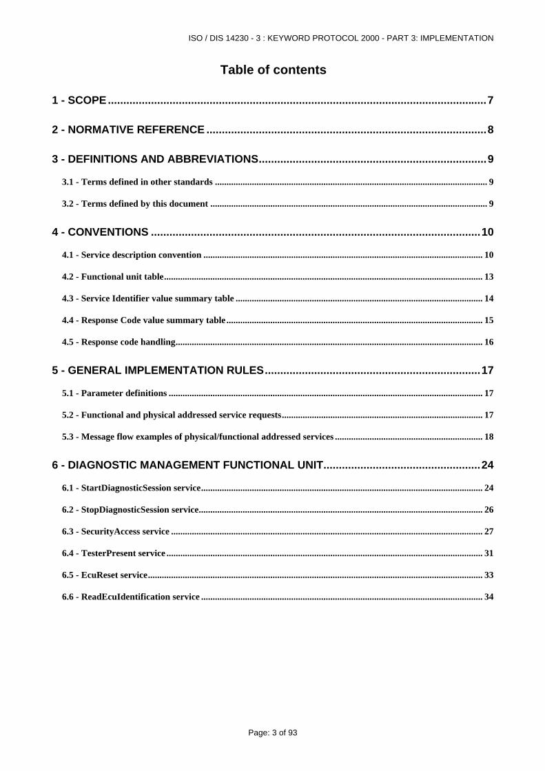
Table of contents
1 - SCOPE...........................................................................................................................7
2 - NORMATIVE REFERENCE ...........................................................................................8
3 - DEFINITIONS AND ABBREVIATIONS..........................................................................9
3.1 - Terms defined in other standards ...................................................................................................................... 9
3.2 - Terms defined by this document ........................................................................................................................ 9
4 - CONVENTIONS ...........................................................................................................10
4.1 - Service description convention ......................................................................................................................... 10
4.2 - Functional unit table.......................................................................................................................................... 13
4.3 - Service Identifier value summary table ........................................................................................................... 14
4.4 - Response Code value summary table ............................................................................................................... 15
4.5 - Response code handling..................................................................................................................................... 16
5 - GENERAL IMPLEMENTATION RULES......................................................................17
5.1 - Parameter definitions ........................................................................................................................................ 17
5.2 - Functional and physical addressed service requests....................................................................................... 17
5.3 - Message flow examples of physical/functional addressed services ................................................................ 18
6 - DIAGNOSTIC MANAGEMENT FUNCTIONAL UNIT...................................................24
6.1 - StartDiagnosticSession service.......................................................................................................................... 24
6.2 - StopDiagnosticSession service........................................................................................................................... 26
6.3 - SecurityAccess service ....................................................................................................................................... 27
6.4 - TesterPresent service ......................................................................................................................................... 31
6.5 - EcuReset service................................................................................................................................................. 33
6.6 - ReadEcuIdentification service .......................................................................................................................... 34
ISO / DIS 14230 - 3 : KEYWORD PROTOCOL 2000 - PART 3: IMPLEMENTATION
Page: 4 of 93
7 - DATA TRANSMISSION FUNCTIONAL UNIT..............................................................36
7.1 - ReadDataByLocalIdentifier service ................................................................................................................. 36
7.2 - ReadDataByCommonIdentifier service ........................................................................................................... 39
7.3 - ReadMemoryByAddress service....................................................................................................................... 41
7.4 - DynamicallyDefineLocalIdentifier service....................................................................................................... 43
7.5 - WriteDataByLocalIdentifier service ................................................................................................................ 49
7.6 - WriteDataByCommonIdentifier service .......................................................................................................... 50
7.7 - WriteMemoryByAddress service...................................................................................................................... 51
7.8 - SetDataRates service.......................................................................................................................................... 52
8 - STORED DATA TRANSMISSION FUNCTIONAL UNIT..............................................53
8.1 - ReadDiagnosticTroubleCodes service.............................................................................................................. 54
8.2 - ReadDiagnosticTroubleCodesByStatus service .............................................................................................. 55
8.3 - ReadStatusOfDiagnosticTroubleCodes service............................................................................................... 57
8.4 - ReadFreezeFrameData service ......................................................................................................................... 58
8.5 - ClearDiagnosticInformation service ................................................................................................................ 62
9 - INPUTOUTPUT CONTROL FUNCTIONAL UNIT ........................................................64
9.1 - InputOutputControlByLocalIdentifier service ............................................................................................... 64
9.2 - InputOutputControlByCommonIdentifier service ......................................................................................... 65
10 - REMOTE ACTIVATION OF ROUTINE FUNCTIONAL UNIT.....................................67
10.1 - StartRoutineByLocalIdentifier service .......................................................................................................... 67
10.2 - StartRoutineByAddress service ...................................................................................................................... 69
10.3 - StopRoutineByLocalIdentifier service ........................................................................................................... 70
10.4 - StopRoutineByAddress service....................................................................................................................... 72
10.5 - RequestRoutineResultsByLocalIdentifier service......................................................................................... 73
10.6 - RequestRoutineResultsByAddress service .................................................................................................... 74
ISO / DIS 14230 - 3 : KEYWORD PROTOCOL 2000 - PART 3: IMPLEMENTATION
Page: 5 of 93
11 - UPLOAD DOWNLOAD FUNCTIONAL UNIT.............................................................76
11.1 - RequestDownload service................................................................................................................................ 76
11.2 - RequestUpload service..................................................................................................................................... 77
11.3 - TransferData service ....................................................................................................................................... 79
11.4 - RequestTransferExit service........................................................................................................................... 81
12 - KEYWORD PROTOCOL 2000 EXTENDED SERVICE..............................................83
12.1 - EscapeCode service.......................................................................................................................................... 83
13 - APPLICATION EXAMPLES.......................................................................................85
13.1 - Description of the on-vehicle ECUs................................................................................................................ 85
13.2 - Functional initialisation and functional addressed communication............................................................ 86
13.3 - Single and multiple response messages and termination of communication.............................................. 86
13.4 - SecurityAccess, data transfer and modification of timing parameters ....................................................... 87
13.5 - ReadDataByLocalIdentifier service with dynamicallyDefineLocalIdentifier ............................................ 90
ISO / DIS 14230 - 3 : KEYWORD PROTOCOL 2000 - PART 3: IMPLEMENTATION
Page: 6 of 93
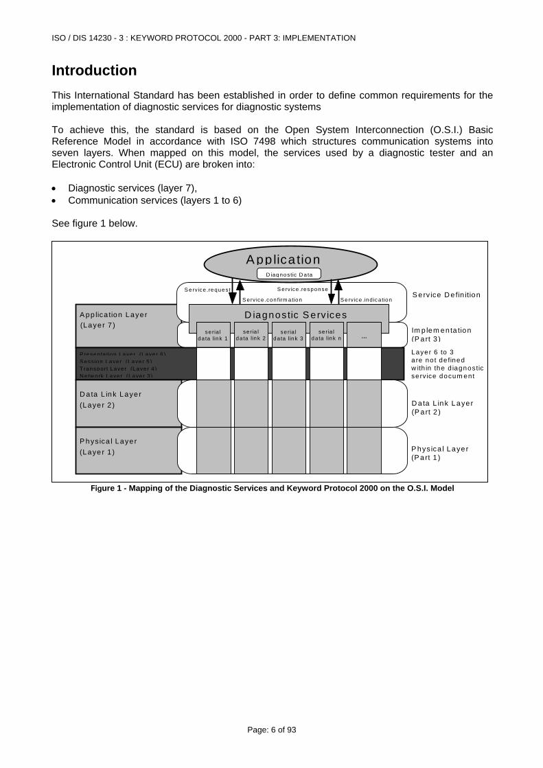
Introduction This International Standard has been established in order to define common requirements for the implementation of diagnostic services for diagnostic systems To achieve this, the standard is based on the Open System Interconnection (O.S.I.) Basic Reference Model in accordance with ISO 7498 which structures communication systems into seven layers. When mapped on this model, the services used by a diagnostic tester and an Electronic Control Unit (ECU) are broken into: • Diagnostic services (layer 7), • Communication services (layers 1 to 6) See figure 1 below.
A pp lica tion Layer
A pp lica tion
S erv ice .request
S erv ice .con firm a tion
S erv ice .response
S erv ice .ind ica tion
(Layer 7 )Im p lem enta tion(P art 3 )
S erv ice D e fin ition
D ata L ink Layer(P art 2 )
P hys ica l Layer(P art 1 )
D iagnostic S erv ices
D ata L ink Layer(Laye r 2 )
P hysica l Layer(Laye r 1 )
S ess ion Layer (Layer 5)P resenta tion Laye r (Laye r 6 )
N e tw ork Laye r (Laye r 3)T ransport Layer (Layer 4 )
Layer 6 to 3are no t de finedw ith in the d iagnosticserv ice docum ent
D iagnostic D a ta
...se ria l
da ta link 1se ria l
da ta link 2se ria l
da ta link 3se ria l
da ta link n
Figure 1 - Mapping of the Diagnostic Services and Keyword Protocol 2000 on the O.S.I. Model
ISO / DIS 14230 - 3 : KEYWORD PROTOCOL 2000 - PART 3: IMPLEMENTATION
Page: 7 of 93
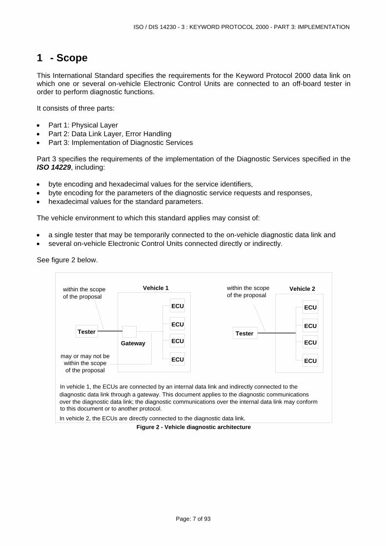
1 - Scope This International Standard specifies the requirements for the Keyword Protocol 2000 data link on which one or several on-vehicle Electronic Control Units are connected to an off-board tester in order to perform diagnostic functions. It consists of three parts: • Part 1: Physical Layer • Part 2: Data Link Layer, Error Handling • Part 3: Implementation of Diagnostic Services Part 3 specifies the requirements of the implementation of the Diagnostic Services specified in the ISO 14229, including: • byte encoding and hexadecimal values for the service identifiers, • byte encoding for the parameters of the diagnostic service requests and responses, • hexadecimal values for the standard parameters. The vehicle environment to which this standard applies may consist of: • a single tester that may be temporarily connected to the on-vehicle diagnostic data link and • several on-vehicle Electronic Control Units connected directly or indirectly. See figure 2 below.
Tester
Gateway
within the scopeof the proposal
ECU
ECU
ECU
ECU
may or may not bewithin the scope of the proposal
Vehicle 1
Tester
within the scopeof the proposal
ECU
ECU
ECU
ECU
Vehicle 2
In vehicle 1, the ECUs are connected by an internal data link and indirectly connected to the diagnostic data link through a gateway. This document applies to the diagnostic communications over the diagnostic data link; the diagnostic communications over the internal data link may conform to this document or to another protocol.
In vehicle 2, the ECUs are directly connected to the diagnostic data link. Figure 2 - Vehicle diagnostic architecture
ISO / DIS 14230 - 3 : KEYWORD PROTOCOL 2000 - PART 3: IMPLEMENTATION
Page: 8 of 93
2 - Normative reference The following standards contain provisions which, through reference in this text, constitute provisions of this document. All standards are subject to revision, and parties to agreement based on this document are encouraged to investigate the possibility of applying the most recent editions of the standards listed below. Members of ISO maintain registers of currently valid International Standards. ISO 7498-1:1984 Information processing systems - Open systems interconnection -
Basic reference model. ISO TR 8509:1987 Information processing systems - Open systems interconnection -
Conventions of services. ISO 4092:1988/Cor.1:1991 Road vehicles - Testers for motor vehicles - Vocabulary Technical
Corrigendum 1. ISO 9141-2 CARB Requirements for Interchange of Digital Information ISO 14229 Road Vehicles - Diagnostic Systems - Diagnostic Services
Specification ISO 14230-1:1996 Road Vehicles - Diagnostic systems - Keyword Protocol 2000 -
Part 1: Physical Layer ISO 14230-2:1996 Road Vehicles - Diagnostic systems - Keyword Protocol 2000 -
Part 2: Data Link Layer ISO 14230-4:1996 Road Vehicles - Diagnostic systems - Keyword Protocol 2000 -
Part 4: Requirements For Emission Related Systems SAE J1587 Joint SAE/TMC Electronic Data Interchange Between
Microcomputer Systems in Heavy-Duty Vehicle Applications SAE J1930 E/E Systems Diagnostic Terms, Definitions, Abbreviations &
Acronyms SAE J1962 Diagnostic Connector SAE J1978 OBD II Scan Tool SAE J1979 E/E Diagnostic Test Modes SAE J2012 Diagnostic Trouble Code Definitions SAE J2186 E/E Diagnostic Data Link Security SAE J2190 Enhanced Diagnostic Test Modes
ISO / DIS 14230 - 3 : KEYWORD PROTOCOL 2000 - PART 3: IMPLEMENTATION
Page: 9 of 93
3 - Definitions and abbreviations
3.1 - Terms defined in other standards
3.1.1 - ISO definitions This document makes use of terms defined in the ISO 14229 Diagnostic Services Specification document.
3.1.2 - SAE definitions This document makes use of terms defined in the SAE J1930 E/E Systems Diagnostic Terms, Definitions, Abbreviations & Acronyms document.
3.2 - Terms defined by this document
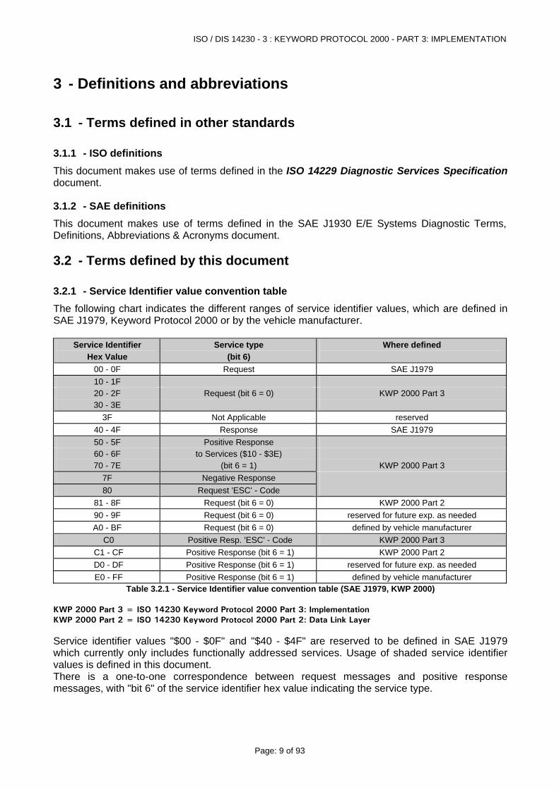
3.2.1 - Service Identifier value convention table The following chart indicates the different ranges of service identifier values, which are defined in SAE J1979, Keyword Protocol 2000 or by the vehicle manufacturer.
Service Identifier Hex Value
Service type (bit 6)
Where defined
00 - 0F Request SAE J1979 10 - 1F 20 - 2F Request (bit 6 = 0) KWP 2000 Part 3 30 - 3E
3F Not Applicable reserved 40 - 4F Response SAE J1979 50 - 5F Positive Response 60 - 6F to Services ($10 - $3E) 70 - 7E (bit 6 = 1) KWP 2000 Part 3
7F Negative Response 80 Request 'ESC' - Code
81 - 8F Request (bit 6 = 0) KWP 2000 Part 2 90 - 9F Request (bit 6 = 0) reserved for future exp. as needed A0 - BF Request (bit 6 = 0) defined by vehicle manufacturer
C0 Positive Resp. 'ESC' - Code KWP 2000 Part 3 C1 - CF Positive Response (bit 6 = 1) KWP 2000 Part 2 D0 - DF Positive Response (bit 6 = 1) reserved for future exp. as needed E0 - FF Positive Response (bit 6 = 1) defined by vehicle manufacturer
Table 3.2.1 - Service Identifier value convention table (SAE J1979, KWP 2000) KWP 2000 Part 3 = ISO 14230 Keyword Protocol 2000 Part 3: Implementation KWP 2000 Part 2 = ISO 14230 Keyword Protocol 2000 Part 2: Data Link Layer Service identifier values "$00 - $0F" and "$40 - $4F" are reserved to be defined in SAE J1979 which currently only includes functionally addressed services. Usage of shaded service identifier values is defined in this document. There is a one-to-one correspondence between request messages and positive response messages, with "bit 6" of the service identifier hex value indicating the service type.
ISO / DIS 14230 - 3 : KEYWORD PROTOCOL 2000 - PART 3: IMPLEMENTATION
Page: 10 of 93
4 - Conventions This document is guided by the conventions discussed in the O.S.I. Service Conventions (ISO/TR 8509) as they apply to the diagnostic services. These conventions define the interactions between the service user and the service provider. Information is passed between the service user and the service provider by service primitives, which may convey parameters.
4.1 - Service description convention This section defines the layout used to describe the diagnostic services. It includes: • Parameter Definition • Message Data Bytes • Message Description • Message Flow Example
4.1.1 - Parameter definition This section defines the use and the values of parameters used by the service.
4.1.2 - Message data bytes The definition of each message includes a table which lists the parameters of its primitives: request/indication ("Req/Ind"), response/confirmation ("Rsp/Cnf") for positive or negative result. All have the same structure. The first table (refer to section 4.1.2.1) describes the request message, the second table (refer to section 4.1.2.2) the positive response message and the third table (refer to section 4.1.2.3) the negative response message. Thus, only a positive or a negative response message may be used; both are listed in separate tables because the list of parameters differ between positive and negative response messages.
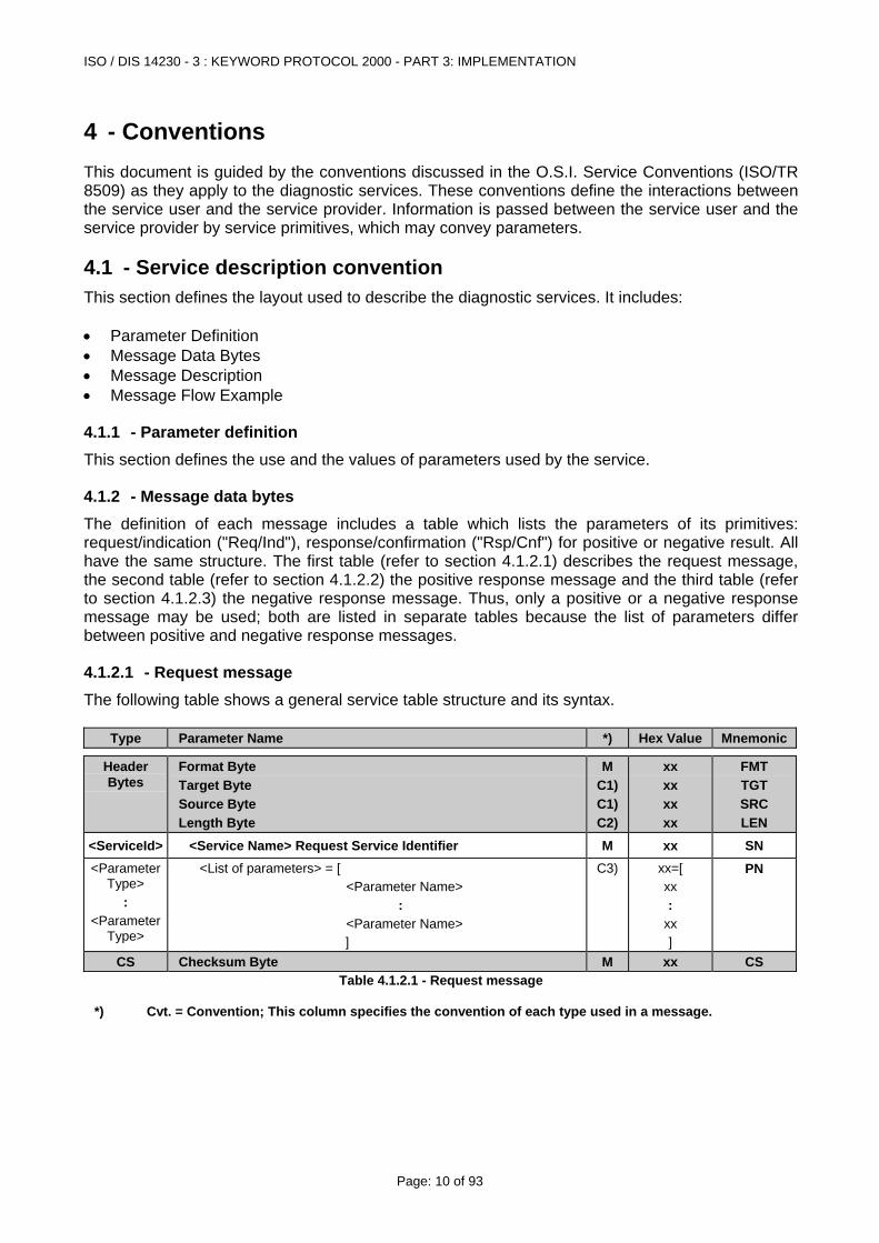
4.1.2.1 - Request message The following table shows a general service table structure and its syntax.
Type Parameter Name *) Hex Value Mnemonic
Header Bytes
Format Byte Target Byte Source Byte Length Byte
M C1)C1)C2)
xx xx xx xx
FMT TGT SRC LEN
<ServiceId> <Service Name> Request Service Identifier M xx SN <Parameter
Type> :
<Parameter Type>
<List of parameters> = [ <Parameter Name> : <Parameter Name> ]
C3) xx=[ xx :
xx ]
PN
CS Checksum Byte M xx CS Table 4.1.2.1 - Request message
*) Cvt. = Convention; This column specifies the convention of each type used in a message.
ISO / DIS 14230 - 3 : KEYWORD PROTOCOL 2000 - PART 3: IMPLEMENTATION
Page: 11 of 93
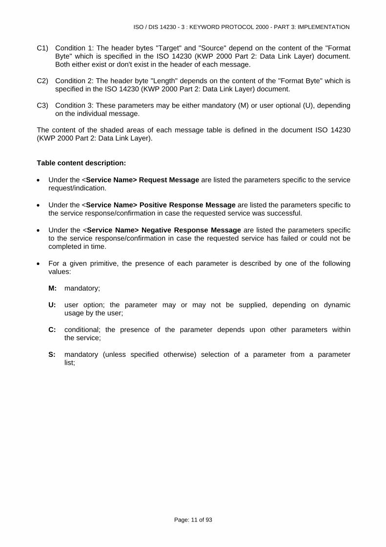
C1) Condition 1: The header bytes "Target" and "Source" depend on the content of the "Format Byte" which is specified in the ISO 14230 (KWP 2000 Part 2: Data Link Layer) document. Both either exist or don't exist in the header of each message.
C2) Condition 2: The header byte "Length" depends on the content of the "Format Byte" which is
specified in the ISO 14230 (KWP 2000 Part 2: Data Link Layer) document. C3) Condition 3: These parameters may be either mandatory (M) or user optional (U), depending
on the individual message. The content of the shaded areas of each message table is defined in the document ISO 14230 (KWP 2000 Part 2: Data Link Layer). Table content description: • Under the <Service Name> Request Message are listed the parameters specific to the service
request/indication. • Under the <Service Name> Positive Response Message are listed the parameters specific to
the service response/confirmation in case the requested service was successful. • Under the <Service Name> Negative Response Message are listed the parameters specific
to the service response/confirmation in case the requested service has failed or could not be completed in time.
• For a given primitive, the presence of each parameter is described by one of the following
values:
M: mandatory;
U: user option; the parameter may or may not be supplied, depending on dynamic usage by the user;
C: conditional; the presence of the parameter depends upon other parameters within
the service; S: mandatory (unless specified otherwise) selection of a parameter from a parameter
list;
ISO / DIS 14230 - 3 : KEYWORD PROTOCOL 2000 - PART 3: IMPLEMENTATION
Page: 12 of 93
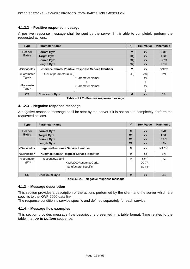
4.1.2.2 - Positive response message A positive response message shall be sent by the server if it is able to completely perform the requested actions.
Type Parameter Name *) Hex Value Mnemonic
Header Bytes
Format Byte Target Byte Source Byte Length Byte
MC1)C1)C2)
xx xx xx xx
FMT TGT SRC LEN
<ServiceId> <Service Name> Positive Response Service Identifier M xx SNPR <Parameter
Type> :
<Parameter Type>
<List of parameters> = [ <Parameter Name> : <Parameter Name> ]
C3) xx=[ xx :
xx ]
PN
CS Checksum Byte M xx CS Table 4.1.2.2 - Positive response message
4.1.2.3 - Negative response message A negative response message shall be sent by the server if it is not able to completely perform the requested actions.
Type Parameter Name *) Hex Value Mnemonic
Header Bytes
Format Byte Target Byte Source Byte Length Byte
M C1)C1)C2)
xx xx xx xx
FMT TGT SRC LEN
<ServiceId> negativeResponse Service Identifier M xx NACK
<ServiceId> <Service Name> Request Service Identifier M xx SN <Parameter
Type> responseCode=[
KWP2000ResponseCode, manufacturerSpecific ]
M xx=[ 00-7F, 80-FF
]
RC
CS Checksum Byte M xx CS Table 4.1.2.3 - Negative response message
4.1.3 - Message description This section provides a description of the actions performed by the client and the server which are specific to the KWP 2000 data link. The response condition is service specific and defined separately for each service.
4.1.4 - Message flow examples This section provides message flow descriptions presented in a table format. Time relates to the table in a top to bottom sequence.
ISO / DIS 14230 - 3 : KEYWORD PROTOCOL 2000 - PART 3: IMPLEMENTATION
Page: 13 of 93
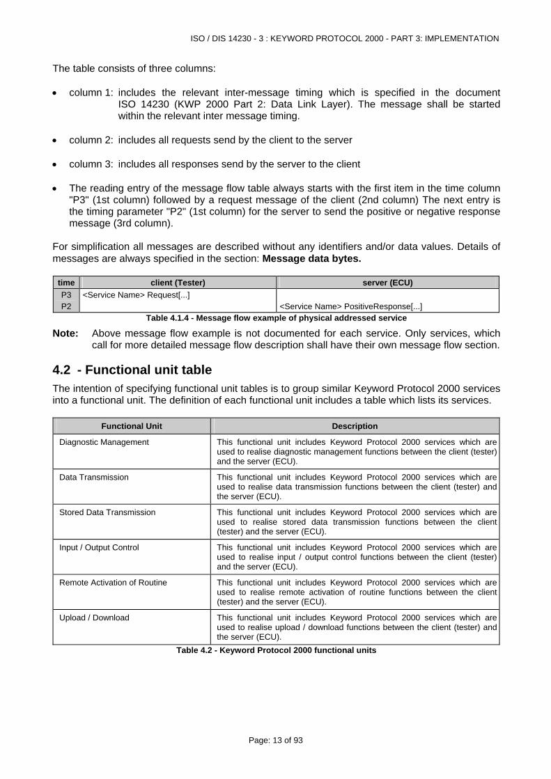
The table consists of three columns: • column 1: includes the relevant inter-message timing which is specified in the document
ISO 14230 (KWP 2000 Part 2: Data Link Layer). The message shall be started within the relevant inter message timing.
• column 2: includes all requests send by the client to the server • column 3: includes all responses send by the server to the client • The reading entry of the message flow table always starts with the first item in the time column
"P3" (1st column) followed by a request message of the client (2nd column) The next entry is the timing parameter "P2" (1st column) for the server to send the positive or negative response message (3rd column).
For simplification all messages are described without any identifiers and/or data values. Details of messages are always specified in the section: Message data bytes.
time client (Tester) server (ECU) P3 P2
<Service Name> Request[...]
<Service Name> PositiveResponse[...]
Table 4.1.4 - Message flow example of physical addressed service
Note: Above message flow example is not documented for each service. Only services, which call for more detailed message flow description shall have their own message flow section.
4.2 - Functional unit table The intention of specifying functional unit tables is to group similar Keyword Protocol 2000 services into a functional unit. The definition of each functional unit includes a table which lists its services.
Functional Unit Description
Diagnostic Management This functional unit includes Keyword Protocol 2000 services which are used to realise diagnostic management functions between the client (tester) and the server (ECU).
Data Transmission This functional unit includes Keyword Protocol 2000 services which are used to realise data transmission functions between the client (tester) and the server (ECU).
Stored Data Transmission This functional unit includes Keyword Protocol 2000 services which are used to realise stored data transmission functions between the client (tester) and the server (ECU).
Input / Output Control This functional unit includes Keyword Protocol 2000 services which are used to realise input / output control functions between the client (tester) and the server (ECU).
Remote Activation of Routine This functional unit includes Keyword Protocol 2000 services which are used to realise remote activation of routine functions between the client (tester) and the server (ECU).
Upload / Download This functional unit includes Keyword Protocol 2000 services which are used to realise upload / download functions between the client (tester) and the server (ECU).
Table 4.2 - Keyword Protocol 2000 functional units
ISO / DIS 14230 - 3 : KEYWORD PROTOCOL 2000 - PART 3: IMPLEMENTATION
Page: 14 of 93
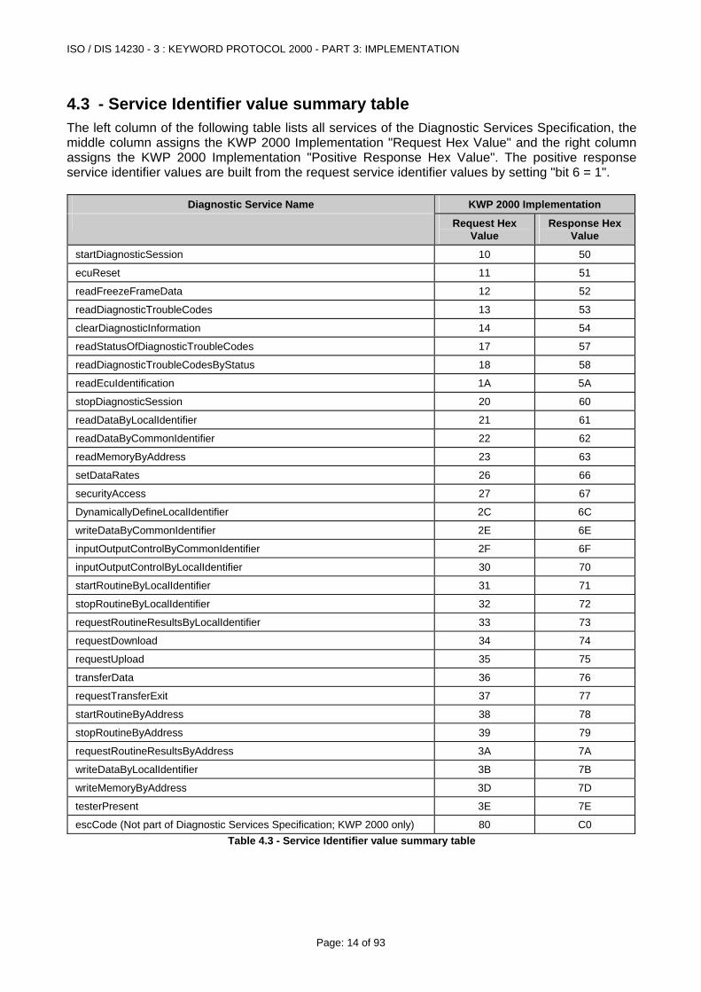
4.3 - Service Identifier value summary table The left column of the following table lists all services of the Diagnostic Services Specification, the middle column assigns the KWP 2000 Implementation "Request Hex Value" and the right column assigns the KWP 2000 Implementation "Positive Response Hex Value". The positive response service identifier values are built from the request service identifier values by setting "bit 6 = 1".
Diagnostic Service Name KWP 2000 Implementation
Request Hex Value
Response Hex Value
startDiagnosticSession 10 50
ecuReset 11 51
readFreezeFrameData 12 52
readDiagnosticTroubleCodes 13 53
clearDiagnosticInformation 14 54
readStatusOfDiagnosticTroubleCodes 17 57
readDiagnosticTroubleCodesByStatus 18 58
readEcuIdentification 1A 5A
stopDiagnosticSession 20 60
readDataByLocalIdentifier 21 61
readDataByCommonIdentifier 22 62
readMemoryByAddress 23 63
setDataRates 26 66
securityAccess 27 67
DynamicallyDefineLocalIdentifier 2C 6C
writeDataByCommonIdentifier 2E 6E
inputOutputControlByCommonIdentifier 2F 6F
inputOutputControlByLocalIdentifier 30 70
startRoutineByLocalIdentifier 31 71
stopRoutineByLocalIdentifier 32 72
requestRoutineResultsByLocalIdentifier 33 73
requestDownload 34 74
requestUpload 35 75
transferData 36 76
requestTransferExit 37 77
startRoutineByAddress 38 78
stopRoutineByAddress 39 79
requestRoutineResultsByAddress 3A 7A
writeDataByLocalIdentifier 3B 7B
writeMemoryByAddress 3D 7D
testerPresent 3E 7E
escCode (Not part of Diagnostic Services Specification; KWP 2000 only) 80 C0 Table 4.3 - Service Identifier value summary table
ISO / DIS 14230 - 3 : KEYWORD PROTOCOL 2000 - PART 3: IMPLEMENTATION
Page: 15 of 93
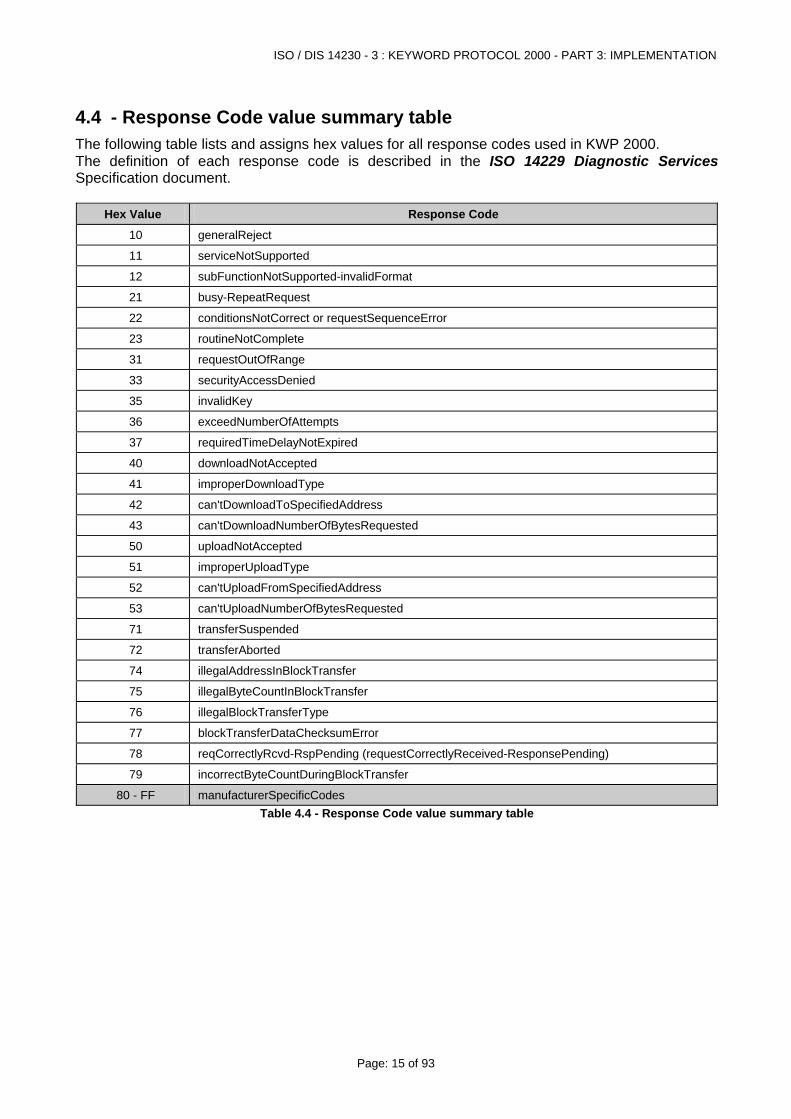
4.4 - Response Code value summary table The following table lists and assigns hex values for all response codes used in KWP 2000. The definition of each response code is described in the ISO 14229 Diagnostic Services Specification document.
Hex Value Response Code
10 generalReject
11 serviceNotSupported
12 subFunctionNotSupported-invalidFormat
21 busy-RepeatRequest
22 conditionsNotCorrect or requestSequenceError
23 routineNotComplete
31 requestOutOfRange
33 securityAccessDenied
35 invalidKey
36 exceedNumberOfAttempts
37 requiredTimeDelayNotExpired
40 downloadNotAccepted
41 improperDownloadType
42 can'tDownloadToSpecifiedAddress
43 can'tDownloadNumberOfBytesRequested
50 uploadNotAccepted
51 improperUploadType
52 can'tUploadFromSpecifiedAddress
53 can'tUploadNumberOfBytesRequested
71 transferSuspended
72 transferAborted
74 illegalAddressInBlockTransfer
75 illegalByteCountInBlockTransfer
76 illegalBlockTransferType
77 blockTransferDataChecksumError
78 reqCorrectlyRcvd-RspPending (requestCorrectlyReceived-ResponsePending)
79 incorrectByteCountDuringBlockTransfer
80 - FF manufacturerSpecificCodes Table 4.4 - Response Code value summary table
ISO / DIS 14230 - 3 : KEYWORD PROTOCOL 2000 - PART 3: IMPLEMENTATION
Page: 16 of 93
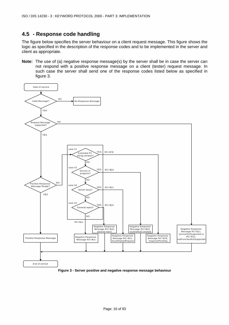
4.5 - Response code handling The figure below specifies the server behaviour on a client request message. This figure shows the logic as specified in the description of the response codes and to be implemented in the server and client as appropriate. Note: The use of (a) negative response message(s) by the server shall be in case the server can
not respond with a positive response message on a client (tester) request message. In such case the server shall send one of the response codes listed below as specified in figure 3.
Start of serv ice
No Response M essage
Request Message supported?
Valid Message?
Positive Response M essage Ready?
Extended P2 tim ing w indow?
Service in progress?
Server busy?
General reject?
End of service
Positive Response Message Negative Response Message RC=$xx
Negative Response Message RC=$10,
general reject
Negative Response Message RC=$21, busyRepeatRequest
Negative Response Message RC=$23, routineNotComplete
Negative Response Message RC=$11,
serv iceNotSupported or RC=$12,
subFunctionNotSupported
Negative Response Message RC=$78, responsePending
NO
NO
NO
NO
NO
NO
NO
YES
YES
YES
YES
YES
YES
YES
RC=$xx
RC=$78
RC=$23
RC=$21
RC=$10
case #1
case #2
case #3
case #4
Figure 3 - Server positive and negative response message behaviour
ISO / DIS 14230 - 3 : KEYWORD PROTOCOL 2000 - PART 3: IMPLEMENTATION
Page: 17 of 93
5 - General implementation rules
5.1 - Parameter definitions The following rules in regard to parameter definitions shall apply: • The subsequent sections (from section 6. to the end of the document except for the last
section) define the services of each functional unit. In these sections, the service structure makes reference to parameters, in order to describe the allowable values for such parameters. The parameters of general purpose are defined in the Diagnostic Services Specification document. Parameters which are specific to a functional unit are described in the corresponding section.
• This document lists and defines response codes and values. Negative response codes are specified in section 4.4. Other response codes may be reserved either for future definition by this document or for the system designer's specific use.
• This document specifies the parameters which shall be used within each KWP 2000 service. • The sequence of parameters within a service shall not be changed during an implementation. • This document specifies the parameter memoryAddress based on a three (3) byte address
(High Byte, Middle Byte and Low Byte). Additional bytes of specifying the memoryAddress (e.g. memory type identifier, larger address range) may be implemented and is the responsibility of the vehicle manufacturer. This applies to all services which use the memoryAddress parameter.
5.2 - Functional and physical addressed service requests Two (2) different addressing methods are specified in KWP 2000 to send a service request to a server(s). • Functional addressing with a three byte header is used by the client if it doesn't know the
physical address of the server that shall respond to a service request or if more than one (1) server can respond to the request.
• Functional addressing with a one byte header is not possible. • Physical addressing with a three byte header shall always be a dedicated message to one
server. The header of the service request message indicates (target address) which server shall respond to the service request message.
• Physical addressing with a one byte header is possible. • Only those server(s) which are initialised and in a diagnostic session which support the service
request message shall send a response message. • Functional and Physical addressing methods are specified in detail in the document ISO
14230 KWP 2000 Part 2: Data Link Layer. • The data link shall always be initialised prior to sending any of the KWP 2000 services.
ISO / DIS 14230 - 3 : KEYWORD PROTOCOL 2000 - PART 3: IMPLEMENTATION
Page: 18 of 93
5.3 - Message flow examples of physical/functional addressed services
5.3.1 - Physical addressed services
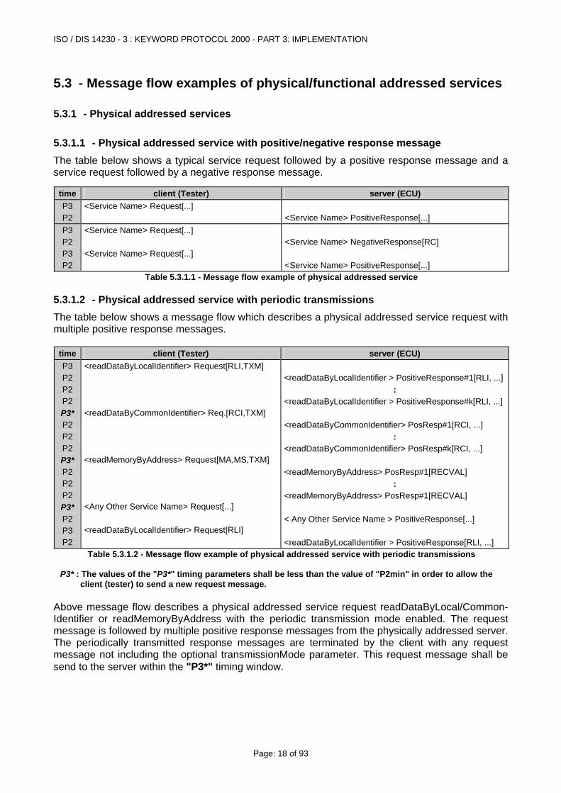
5.3.1.1 - Physical addressed service with positive/negative response message The table below shows a typical service request followed by a positive response message and a service request followed by a negative response message.
time client (Tester) server (ECU) P3 P2
<Service Name> Request[...] <Service Name> PositiveResponse[...]
P3 P2 P3 P2
<Service Name> Request[...] <Service Name> Request[...]
<Service Name> NegativeResponse[RC] <Service Name> PositiveResponse[...]
Table 5.3.1.1 - Message flow example of physical addressed service
5.3.1.2 - Physical addressed service with periodic transmissions The table below shows a message flow which describes a physical addressed service request with multiple positive response messages.
time client (Tester) server (ECU) P3 P2 P2 P2 P3* P2 P2 P2 P3* P2 P2 P2 P3* P2 P3 P2
<readDataByLocalIdentifier> Request[RLI,TXM] <readDataByCommonIdentifier> Req.[RCI,TXM] <readMemoryByAddress> Request[MA,MS,TXM] <Any Other Service Name> Request[...] <readDataByLocalIdentifier> Request[RLI]
<readDataByLocalIdentifier > PositiveResponse#1[RLI, ...]
: <readDataByLocalIdentifier > PositiveResponse#k[RLI, ...] <readDataByCommonIdentifier> PosResp#1[RCI, ...]
: <readDataByCommonIdentifier> PosResp#k[RCI, ...] <readMemoryByAddress> PosResp#1[RECVAL]
: <readMemoryByAddress> PosResp#1[RECVAL] < Any Other Service Name > PositiveResponse[...] <readDataByLocalIdentifier > PositiveResponse[RLI, ...]
Table 5.3.1.2 - Message flow example of physical addressed service with periodic transmissions P3* : The values of the "P3*" timing parameters shall be less than the value of "P2min" in order to allow the
client (tester) to send a new request message. Above message flow describes a physical addressed service request readDataByLocal/Common-Identifier or readMemoryByAddress with the periodic transmission mode enabled. The request message is followed by multiple positive response messages from the physically addressed server. The periodically transmitted response messages are terminated by the client with any request message not including the optional transmissionMode parameter. This request message shall be send to the server within the "P3*" timing window.
ISO / DIS 14230 - 3 : KEYWORD PROTOCOL 2000 - PART 3: IMPLEMENTATION
Page: 19 of 93
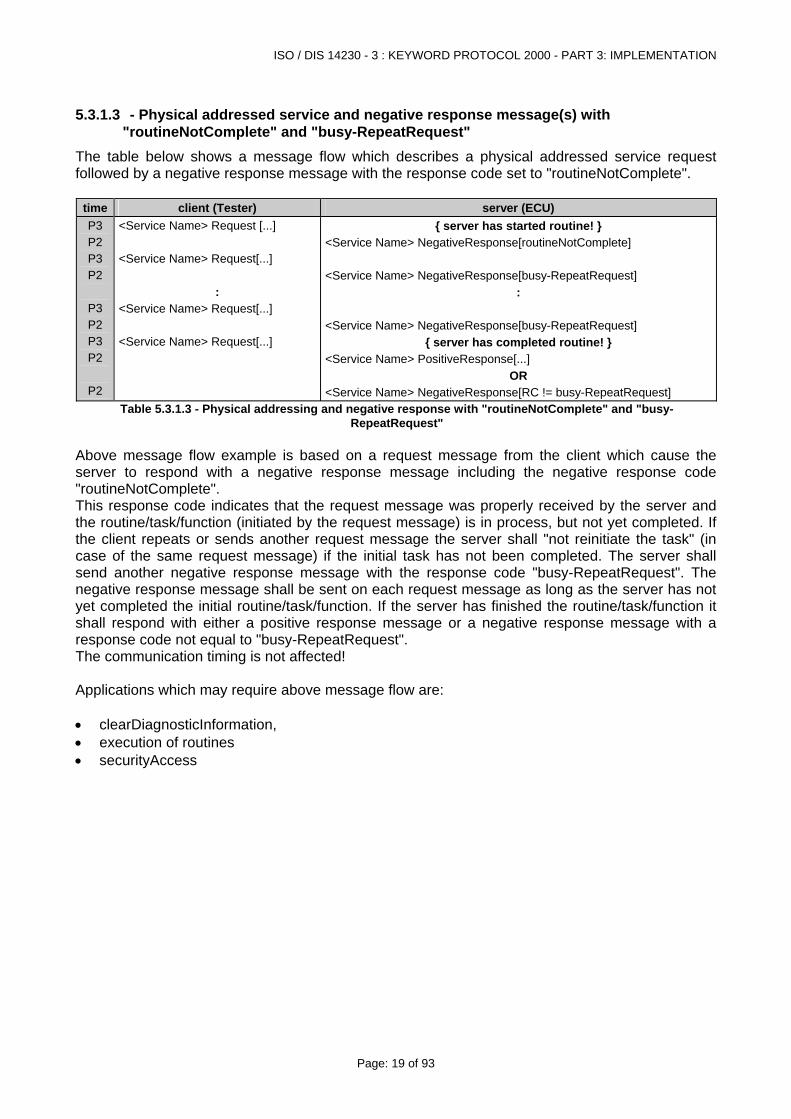
5.3.1.3 - Physical addressed service and negative response message(s) with "routineNotComplete" and "busy-RepeatRequest"
The table below shows a message flow which describes a physical addressed service request followed by a negative response message with the response code set to "routineNotComplete".
time client (Tester) server (ECU) P3 P2 P3 P2
P3 P2 P3 P2
P2
<Service Name> Request [...] <Service Name> Request[...]
: <Service Name> Request[...] <Service Name> Request[...]
{ server has started routine! } <Service Name> NegativeResponse[routineNotComplete] <Service Name> NegativeResponse[busy-RepeatRequest]
: <Service Name> NegativeResponse[busy-RepeatRequest]
{ server has completed routine! } <Service Name> PositiveResponse[...]
OR <Service Name> NegativeResponse[RC != busy-RepeatRequest]
Table 5.3.1.3 - Physical addressing and negative response with "routineNotComplete" and "busy-RepeatRequest"
Above message flow example is based on a request message from the client which cause the server to respond with a negative response message including the negative response code "routineNotComplete". This response code indicates that the request message was properly received by the server and the routine/task/function (initiated by the request message) is in process, but not yet completed. If the client repeats or sends another request message the server shall "not reinitiate the task" (in case of the same request message) if the initial task has not been completed. The server shall send another negative response message with the response code "busy-RepeatRequest". The negative response message shall be sent on each request message as long as the server has not yet completed the initial routine/task/function. If the server has finished the routine/task/function it shall respond with either a positive response message or a negative response message with a response code not equal to "busy-RepeatRequest". The communication timing is not affected! Applications which may require above message flow are: • clearDiagnosticInformation, • execution of routines • securityAccess
ISO / DIS 14230 - 3 : KEYWORD PROTOCOL 2000 - PART 3: IMPLEMENTATION
Page: 20 of 93
5.3.1.4 - Implementation example of "Server can not sent a positive response within required timing"
5.3.1.4.1 - Example of physical addressed service and negative response message with "reqCorrectlyRcvd-RspPending within Normal or Extended Timing"
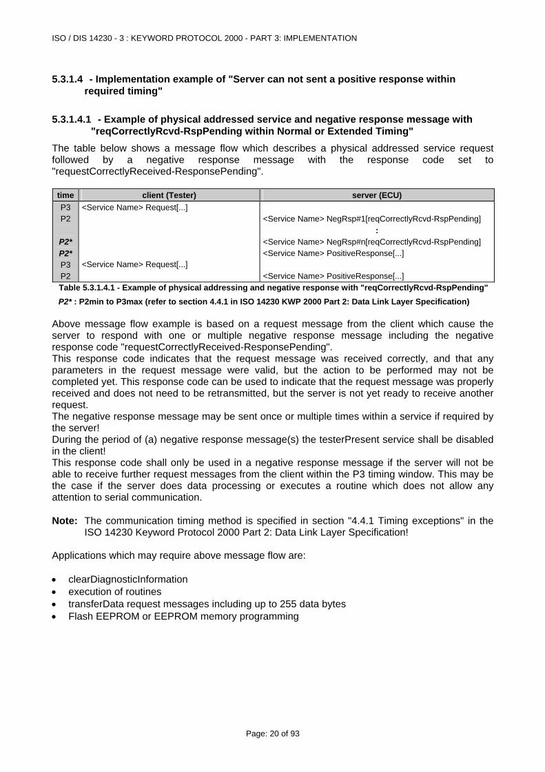
The table below shows a message flow which describes a physical addressed service request followed by a negative response message with the response code set to "requestCorrectlyReceived-ResponsePending".
time client (Tester) server (ECU) P3 P2
P2* P2* P3 P2
<Service Name> Request[...] <Service Name> Request[...]
<Service Name> NegRsp#1[reqCorrectlyRcvd-RspPending]
: <Service Name> NegRsp#n[reqCorrectlyRcvd-RspPending] <Service Name> PositiveResponse[...] <Service Name> PositiveResponse[...]
Table 5.3.1.4.1 - Example of physical addressing and negative response with "reqCorrectlyRcvd-RspPending"
P2* : P2min to P3max (refer to section 4.4.1 in ISO 14230 KWP 2000 Part 2: Data Link Layer Specification) Above message flow example is based on a request message from the client which cause the server to respond with one or multiple negative response message including the negative response code "requestCorrectlyReceived-ResponsePending". This response code indicates that the request message was received correctly, and that any parameters in the request message were valid, but the action to be performed may not be completed yet. This response code can be used to indicate that the request message was properly received and does not need to be retransmitted, but the server is not yet ready to receive another request. The negative response message may be sent once or multiple times within a service if required by the server! During the period of (a) negative response message(s) the testerPresent service shall be disabled in the client! This response code shall only be used in a negative response message if the server will not be able to receive further request messages from the client within the P3 timing window. This may be the case if the server does data processing or executes a routine which does not allow any attention to serial communication. Note: The communication timing method is specified in section "4.4.1 Timing exceptions" in the
ISO 14230 Keyword Protocol 2000 Part 2: Data Link Layer Specification! Applications which may require above message flow are: • clearDiagnosticInformation • execution of routines • transferData request messages including up to 255 data bytes • Flash EEPROM or EEPROM memory programming
ISO / DIS 14230 - 3 : KEYWORD PROTOCOL 2000 - PART 3: IMPLEMENTATION
Page: 21 of 93
5.3.1.4.2 - Implementation of "Server can not sent a positive response within Default Timing"
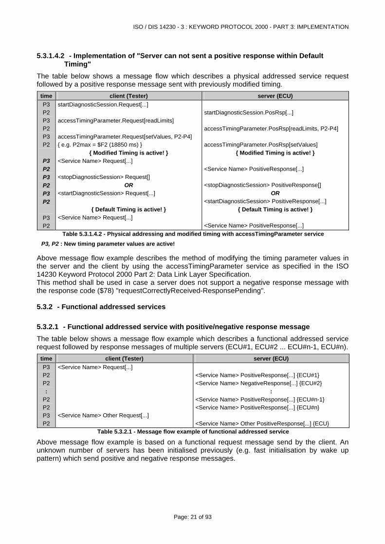
The table below shows a message flow which describes a physical addressed service request followed by a positive response message sent with previously modified timing.
time client (Tester) server (ECU) P3 P2 P3 P2 P3 P2
P3 P2 P3 P2 P3 P2
P3 P2
startDiagnosticSession.Request[...] accessTimingParameter.Request[readLimits] accessTimingParameter.Request[setValues, P2-P4] { e.g. P2max = $F2 (18850 ms) }
{ Modified Timing is active! } <Service Name> Request[...] <stopDiagnosticSession> Request[]
OR <startDiagnosticSession> Request[...]
{ Default Timing is active! } <Service Name> Request[...]
startDiagnosticSession.PosRsp[...] accessTimingParameter.PosRsp[readLimits, P2-P4] accessTimingParameter.PosRsp[setValues]
{ Modified Timing is active! } <Service Name> PositiveResponse[...] <stopDiagnosticSession> PositiveResponse[]
OR <startDiagnosticSession> PositiveResponse[...]
{ Default Timing is active! } <Service Name> PositiveResponse[...]
Table 5.3.1.4.2 - Physical addressing and modified timing with accessTimingParameter service
P3, P2 : New timing parameter values are active!
Above message flow example describes the method of modifying the timing parameter values in the server and the client by using the accessTimingParameter service as specified in the ISO 14230 Keyword Protocol 2000 Part 2: Data Link Layer Specification. This method shall be used in case a server does not support a negative response message with the response code ($78) "requestCorrectlyReceived-ResponsePending".
5.3.2 - Functional addressed services
5.3.2.1 - Functional addressed service with positive/negative response message The table below shows a message flow example which describes a functional addressed service request followed by response messages of multiple servers (ECU#1, ECU#2 ... ECU#n-1, ECU#n).
time client (Tester) server (ECU) P3 P2 P2 :
P2 P2 P3 P2
<Service Name> Request[...] <Service Name> Other Request[...]
<Service Name> PositiveResponse[...] {ECU#1} <Service Name> NegativeResponse[...] {ECU#2}
: <Service Name> PositiveResponse[...] {ECU#n-1} <Service Name> PositiveResponse[...] {ECU#n} <Service Name> Other PositiveResponse[...] {ECU}
Table 5.3.2.1 - Message flow example of functional addressed service
Above message flow example is based on a functional request message send by the client. An unknown number of servers has been initialised previously (e.g. fast initialisation by wake up pattern) which send positive and negative response messages.
ISO / DIS 14230 - 3 : KEYWORD PROTOCOL 2000 - PART 3: IMPLEMENTATION
Page: 22 of 93
5.3.2.2 - Functional addressed service and negative response message(s) with "routineNotComplete" and "busy-RepeatRequest"
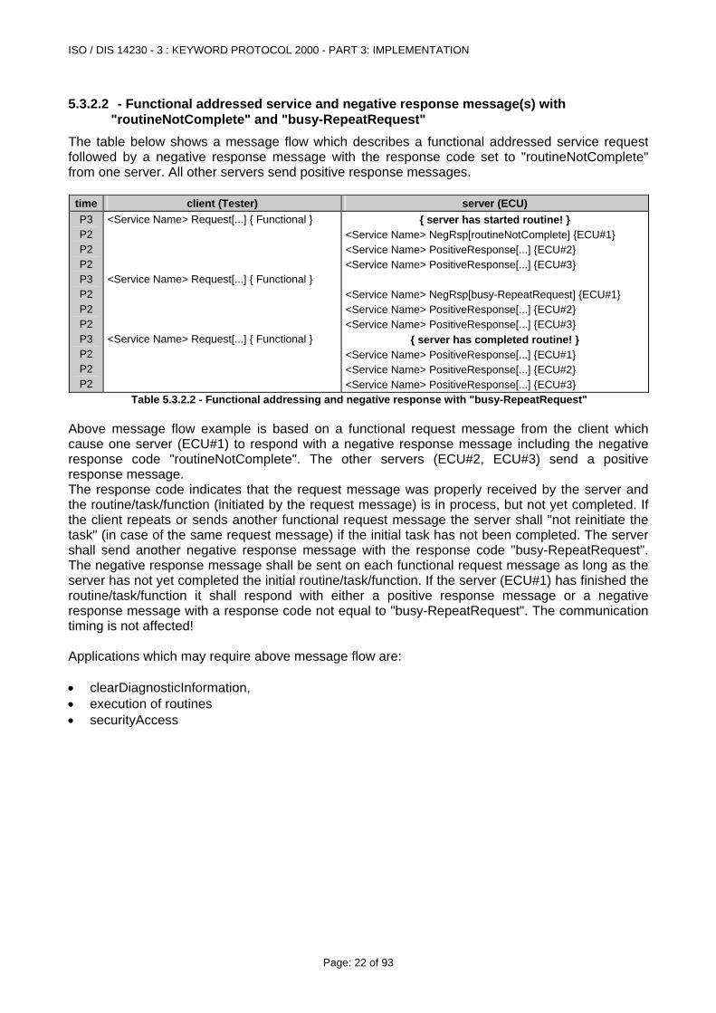
The table below shows a message flow which describes a functional addressed service request followed by a negative response message with the response code set to "routineNotComplete" from one server. All other servers send positive response messages.
time client (Tester) server (ECU) P3 P2 P2 P2 P3 P2 P2 P2 P3 P2 P2 P2
<Service Name> Request[...] { Functional } <Service Name> Request[...] { Functional } <Service Name> Request[...] { Functional }
{ server has started routine! } <Service Name> NegRsp[routineNotComplete] {ECU#1} <Service Name> PositiveResponse[...] {ECU#2} <Service Name> PositiveResponse[...] {ECU#3} <Service Name> NegRsp[busy-RepeatRequest] {ECU#1} <Service Name> PositiveResponse[...] {ECU#2} <Service Name> PositiveResponse[...] {ECU#3}
{ server has completed routine! } <Service Name> PositiveResponse[...] {ECU#1} <Service Name> PositiveResponse[...] {ECU#2} <Service Name> PositiveResponse[...] {ECU#3}
Table 5.3.2.2 - Functional addressing and negative response with "busy-RepeatRequest" Above message flow example is based on a functional request message from the client which cause one server (ECU#1) to respond with a negative response message including the negative response code "routineNotComplete". The other servers (ECU#2, ECU#3) send a positive response message. The response code indicates that the request message was properly received by the server and the routine/task/function (initiated by the request message) is in process, but not yet completed. If the client repeats or sends another functional request message the server shall "not reinitiate the task" (in case of the same request message) if the initial task has not been completed. The server shall send another negative response message with the response code "busy-RepeatRequest". The negative response message shall be sent on each functional request message as long as the server has not yet completed the initial routine/task/function. If the server (ECU#1) has finished the routine/task/function it shall respond with either a positive response message or a negative response message with a response code not equal to "busy-RepeatRequest". The communication timing is not affected! Applications which may require above message flow are: • clearDiagnosticInformation, • execution of routines • securityAccess
ISO / DIS 14230 - 3 : KEYWORD PROTOCOL 2000 - PART 3: IMPLEMENTATION
Page: 23 of 93
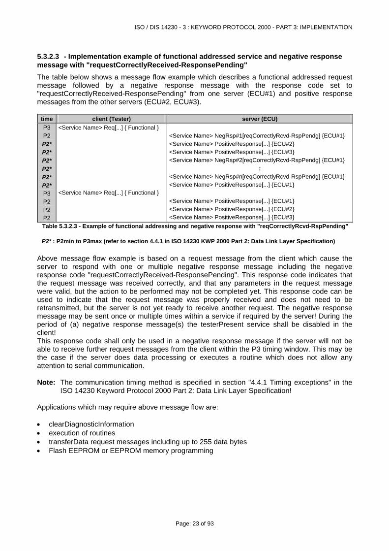
5.3.2.3 - Implementation example of functional addressed service and negative response message with "requestCorrectlyReceived-ResponsePending" The table below shows a message flow example which describes a functional addressed request message followed by a negative response message with the response code set to "requestCorrectlyReceived-ResponsePending" from one server (ECU#1) and positive response messages from the other servers (ECU#2, ECU#3).
time client (Tester) server (ECU) P3 P2 P2* P2* P2* P2* P2* P2* P3 P2 P2 P2
<Service Name> Req[...] { Functional } <Service Name> Req[...] { Functional }
<Service Name> NegRsp#1[reqCorrectlyRcvd-RspPendg] {ECU#1} <Service Name> PositiveResponse[...] {ECU#2} <Service Name> PositiveResponse[...] {ECU#3} <Service Name> NegRsp#2[reqCorrectlyRcvd-RspPendg] {ECU#1}
: <Service Name> NegRsp#n[reqCorrectlyRcvd-RspPendg] {ECU#1} <Service Name> PositiveResponse[...] {ECU#1} <Service Name> PositiveResponse[...] {ECU#1} <Service Name> PositiveResponse[...] {ECU#2} <Service Name> PositiveResponse[...] {ECU#3}
Table 5.3.2.3 - Example of functional addressing and negative response with "reqCorrectlyRcvd-RspPending" P2* : P2min to P3max (refer to section 4.4.1 in ISO 14230 KWP 2000 Part 2: Data Link Layer Specification)
Above message flow example is based on a request message from the client which cause the server to respond with one or multiple negative response message including the negative response code "requestCorrectlyReceived-ResponsePending". This response code indicates that the request message was received correctly, and that any parameters in the request message were valid, but the action to be performed may not be completed yet. This response code can be used to indicate that the request message was properly received and does not need to be retransmitted, but the server is not yet ready to receive another request. The negative response message may be sent once or multiple times within a service if required by the server! During the period of (a) negative response message(s) the testerPresent service shall be disabled in the client! This response code shall only be used in a negative response message if the server will not be able to receive further request messages from the client within the P3 timing window. This may be the case if the server does data processing or executes a routine which does not allow any attention to serial communication. Note: The communication timing method is specified in section "4.4.1 Timing exceptions" in the
ISO 14230 Keyword Protocol 2000 Part 2: Data Link Layer Specification! Applications which may require above message flow are: • clearDiagnosticInformation • execution of routines • transferData request messages including up to 255 data bytes • Flash EEPROM or EEPROM memory programming
ISO / DIS 14230 - 3 : KEYWORD PROTOCOL 2000 - PART 3: IMPLEMENTATION
Page: 24 of 93
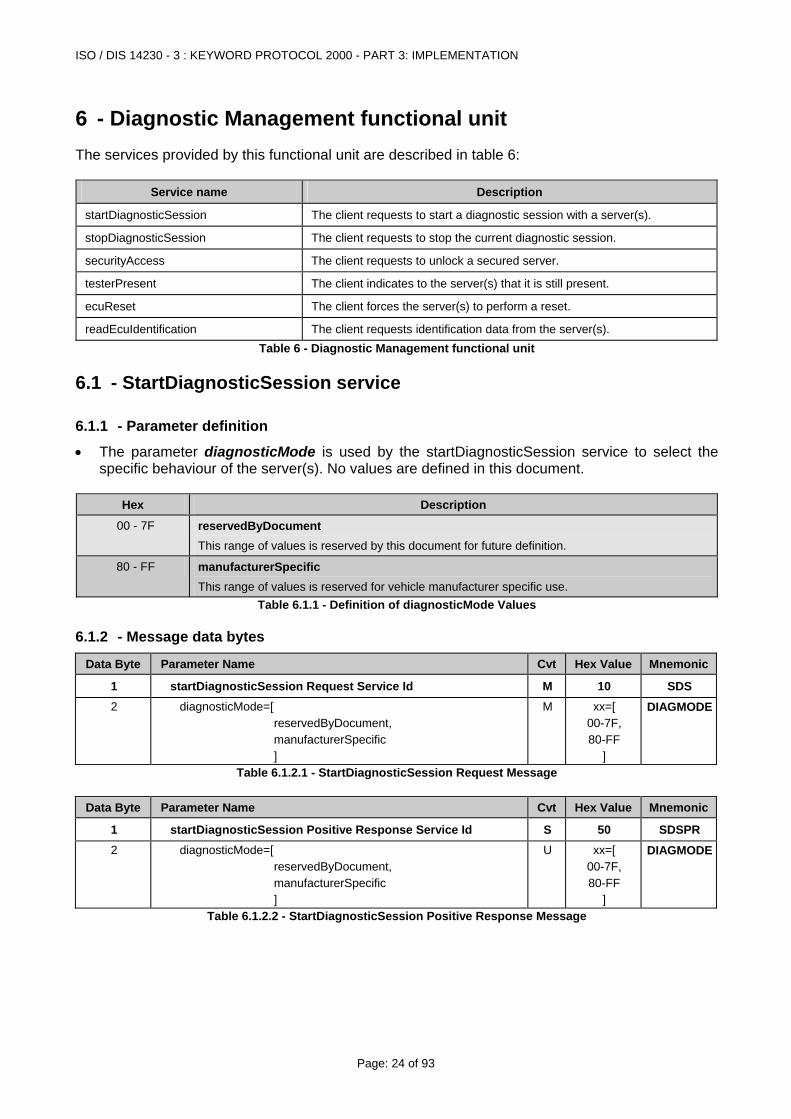
6 - Diagnostic Management functional unit The services provided by this functional unit are described in table 6:
Service name Description
startDiagnosticSession The client requests to start a diagnostic session with a server(s).
stopDiagnosticSession The client requests to stop the current diagnostic session.
securityAccess The client requests to unlock a secured server.
testerPresent The client indicates to the server(s) that it is still present.
ecuReset The client forces the server(s) to perform a reset.
readEcuIdentification The client requests identification data from the server(s). Table 6 - Diagnostic Management functional unit
6.1 - StartDiagnosticSession service
6.1.1 - Parameter definition
• The parameter diagnosticMode is used by the startDiagnosticSession service to select the specific behaviour of the server(s). No values are defined in this document.
Hex Description
00 - 7F reservedByDocument This range of values is reserved by this document for future definition.
80 - FF manufacturerSpecific This range of values is reserved for vehicle manufacturer specific use.
Table 6.1.1 - Definition of diagnosticMode Values
6.1.2 - Message data bytes
Data Byte Parameter Name Cvt Hex Value Mnemonic
1 startDiagnosticSession Request Service Id M 10 SDS 2 diagnosticMode=[
reservedByDocument, manufacturerSpecific ]
M xx=[ 00-7F, 80-FF
]
DIAGMODE
Table 6.1.2.1 - StartDiagnosticSession Request Message
Data Byte Parameter Name Cvt Hex Value Mnemonic
1 startDiagnosticSession Positive Response Service Id S 50 SDSPR 2 diagnosticMode=[
reservedByDocument, manufacturerSpecific ]
U xx=[ 00-7F, 80-FF
]
DIAGMODE
Table 6.1.2.2 - StartDiagnosticSession Positive Response Message
ISO / DIS 14230 - 3 : KEYWORD PROTOCOL 2000 - PART 3: IMPLEMENTATION
Page: 25 of 93
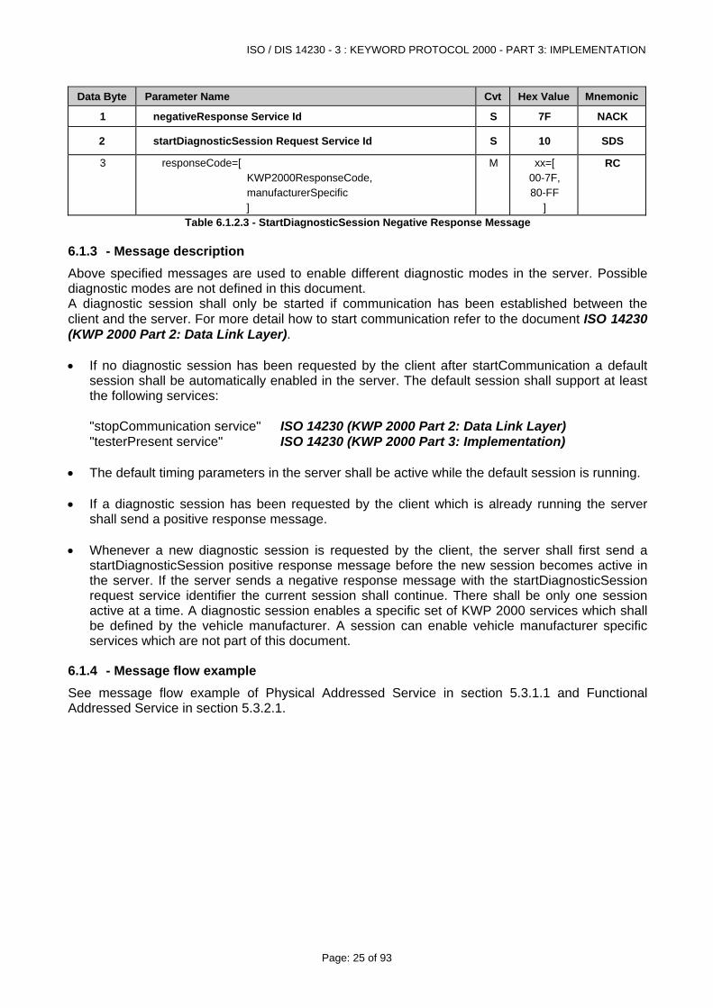
Data Byte Parameter Name Cvt Hex Value Mnemonic
1 negativeResponse Service Id S 7F NACK
2 startDiagnosticSession Request Service Id S 10 SDS
3 responseCode=[ KWP2000ResponseCode, manufacturerSpecific ]
M xx=[ 00-7F, 80-FF
]
RC
Table 6.1.2.3 - StartDiagnosticSession Negative Response Message
6.1.3 - Message description Above specified messages are used to enable different diagnostic modes in the server. Possible diagnostic modes are not defined in this document. A diagnostic session shall only be started if communication has been established between the client and the server. For more detail how to start communication refer to the document ISO 14230 (KWP 2000 Part 2: Data Link Layer). • If no diagnostic session has been requested by the client after startCommunication a default
session shall be automatically enabled in the server. The default session shall support at least the following services:
"stopCommunication service" ISO 14230 (KWP 2000 Part 2: Data Link Layer) "testerPresent service" ISO 14230 (KWP 2000 Part 3: Implementation) • The default timing parameters in the server shall be active while the default session is running. • If a diagnostic session has been requested by the client which is already running the server
shall send a positive response message. • Whenever a new diagnostic session is requested by the client, the server shall first send a
startDiagnosticSession positive response message before the new session becomes active in the server. If the server sends a negative response message with the startDiagnosticSession request service identifier the current session shall continue. There shall be only one session active at a time. A diagnostic session enables a specific set of KWP 2000 services which shall be defined by the vehicle manufacturer. A session can enable vehicle manufacturer specific services which are not part of this document.
6.1.4 - Message flow example See message flow example of Physical Addressed Service in section 5.3.1.1 and Functional Addressed Service in section 5.3.2.1.
ISO / DIS 14230 - 3 : KEYWORD PROTOCOL 2000 - PART 3: IMPLEMENTATION
Page: 26 of 93
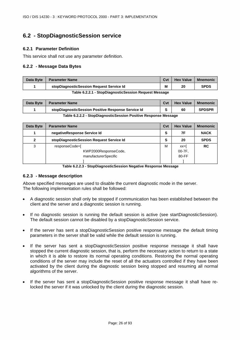
6.2 - StopDiagnosticSession service
6.2.1 Parameter Definition This service shall not use any parameter definition.
6.2.2 - Message Data Bytes
Data Byte Parameter Name Cvt Hex Value Mnemonic
1 stopDiagnosticSession Request Service Id M 20 SPDS Table 6.2.2.1 - StopDiagnosticSession Request Message
Data Byte Parameter Name Cvt Hex Value Mnemonic
1 stopDiagnosticSession Positive Response Service Id S 60 SPDSPRTable 6.2.2.2 - StopDiagnosticSession Positive Response Message
Data Byte Parameter Name Cvt Hex Value Mnemonic
1 negativeResponse Service Id S 7F NACK
2 stopDiagnosticSession Request Service Id S 20 SPDS 3 responseCode=[
KWP2000ResponseCode, manufacturerSpecific ]
M xx=[ 00-7F, 80-FF
]
RC
Table 6.2.2.3 - StopDiagnosticSession Negative Response Message
6.2.3 - Message description Above specified messages are used to disable the current diagnostic mode in the server. The following implementation rules shall be followed: • A diagnostic session shall only be stopped if communication has been established between the
client and the server and a diagnostic session is running. • If no diagnostic session is running the default session is active (see startDiagnosticSession).
The default session cannot be disabled by a stopDiagnosticSession service. • If the server has sent a stopDiagnosticSession positive response message the default timing
parameters in the server shall be valid while the default session is running. • If the server has sent a stopDiagnosticSession positive response message it shall have
stopped the current diagnostic session, that is, perform the necessary action to return to a state in which it is able to restore its normal operating conditions. Restoring the normal operating conditions of the server may include the reset of all the actuators controlled if they have been activated by the client during the diagnostic session being stopped and resuming all normal algorithms of the server.
• If the server has sent a stopDiagnosticSession positive response message it shall have re-
locked the server if it was unlocked by the client during the diagnostic session.
ISO / DIS 14230 - 3 : KEYWORD PROTOCOL 2000 - PART 3: IMPLEMENTATION
Page: 27 of 93
• If a stopDiagnosticSession has been requested by the client and the default session is already running the server shall send a positive response message and immediately reset all timing parameters.
• The client shall send a stopDiagnosticSession request message before disabling
communication via a stopCommunication service but only if a startDiagnosticSession request message has been sent previously.
• If the server sends a negative response message with the stopDiagnosticSession request
service identifier the active session shall be continued. • A stopDiagnosticSession service shall also be used to disable vehicle manufacturer specific
diagnostic sessions.
6.2.4 - Message flow example See message flow example of Physical Addressed Service in section 5.3.1.1 and Functional Addressed Service in section 5.3.2.1.
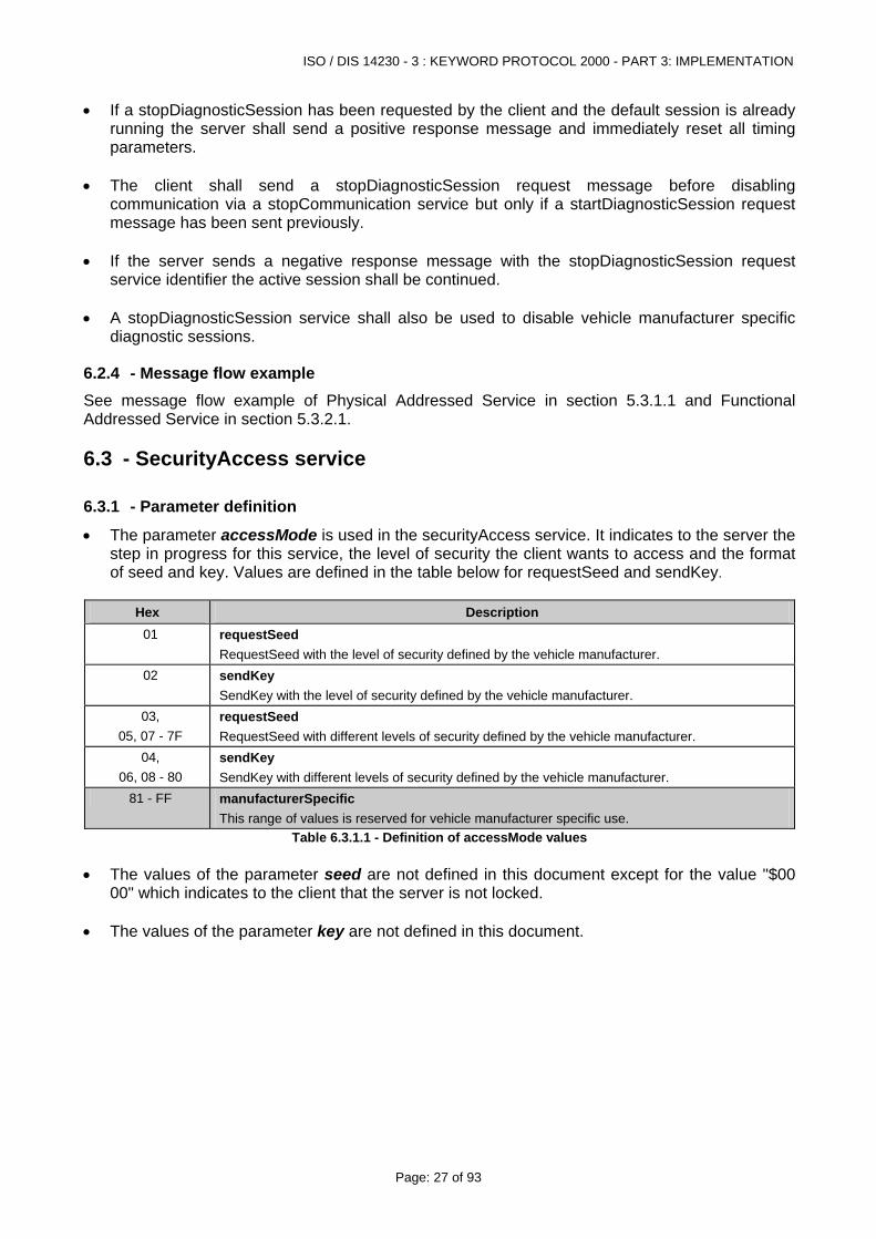
6.3 - SecurityAccess service
6.3.1 - Parameter definition
• The parameter accessMode is used in the securityAccess service. It indicates to the server the step in progress for this service, the level of security the client wants to access and the format of seed and key. Values are defined in the table below for requestSeed and sendKey.
Hex Description
01 requestSeed RequestSeed with the level of security defined by the vehicle manufacturer.
02 sendKey SendKey with the level of security defined by the vehicle manufacturer.
03, 05, 07 - 7F
requestSeed RequestSeed with different levels of security defined by the vehicle manufacturer.
04, 06, 08 - 80
sendKey SendKey with different levels of security defined by the vehicle manufacturer.
81 - FF manufacturerSpecific This range of values is reserved for vehicle manufacturer specific use.
Table 6.3.1.1 - Definition of accessMode values • The values of the parameter seed are not defined in this document except for the value "$00
00" which indicates to the client that the server is not locked. • The values of the parameter key are not defined in this document.
ISO / DIS 14230 - 3 : KEYWORD PROTOCOL 2000 - PART 3: IMPLEMENTATION
Page: 28 of 93
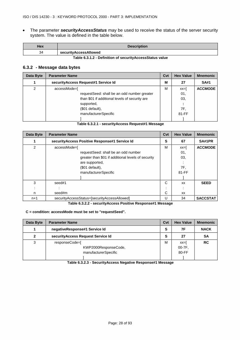
• The parameter securityAccessStatus may be used to receive the status of the server security system. The value is defined in the table below.
Hex Description
34 securityAccessAllowed Table 6.3.1.2 - Definition of securityAccessStatus value
6.3.2 - Message data bytes
Data Byte Parameter Name Cvt Hex Value Mnemonic
1 securityAccess Request#1 Service Id M 27 SA#1 2 accessMode=[
requestSeed: shall be an odd number greater than $01 if additional levels of security are supported, ($01 default), manufacturerSpecific ]
M xx=[ 01, 03, :
7F, 81-FF
]
ACCMODE
Table 6.3.2.1 - securityAccess Request#1 Message
Data Byte Parameter Name Cvt Hex Value Mnemonic
1 securityAccess Positive Response#1 Service Id S 67 SA#1PR 2 accessMode=[
requestSeed: shall be an odd number greater than $01 if additional levels of security are supported, ($01 default), manufacturerSpecific ]
M xx=[ 01, 03, :
7F, 81-FF
]
ACCMODE
3 : n
seed#1 : seed#m
C : C
xx :
xx
SEED
n+1 securityAccessStatus=[securityAccessAllowed] U 34 SACCSTATTable 6.3.2.2 - securityAccess Positive Response#1 Message
C = condition: accessMode must be set to "requestSeed".
Data Byte Parameter Name Cvt Hex Value Mnemonic
1 negativeResponse#1 Service Id S 7F NACK
2 securityAccess Request Service Id S 27 SA 3
responseCode=[ KWP2000ResponseCode, manufacturerSpecific ]
M xx=[ 00-7F, 80-FF
]
RC
Table 6.3.2.3 - SecurityAccess Negative Response#1 Message
ISO / DIS 14230 - 3 : KEYWORD PROTOCOL 2000 - PART 3: IMPLEMENTATION
Page: 29 of 93
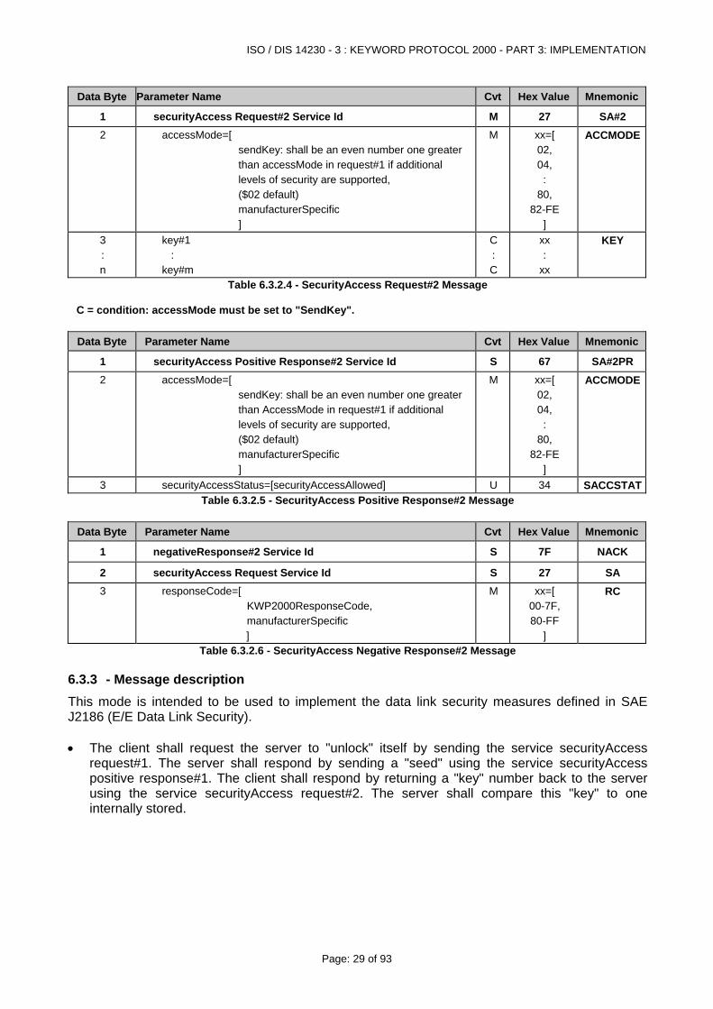
Data Byte Parameter Name Cvt Hex Value Mnemonic
1 securityAccess Request#2 Service Id M 27 SA#2 2 accessMode=[
sendKey: shall be an even number one greater than accessMode in request#1 if additional levels of security are supported, ($02 default) manufacturerSpecific ]
M xx=[ 02, 04, :
80, 82-FE
]
ACCMODE
3 : n
key#1 : key#m
C : C
xx :
xx
KEY
Table 6.3.2.4 - SecurityAccess Request#2 Message C = condition: accessMode must be set to "SendKey".
Data Byte Parameter Name Cvt Hex Value Mnemonic
1 securityAccess Positive Response#2 Service Id S 67 SA#2PR 2
accessMode=[ sendKey: shall be an even number one greater than AccessMode in request#1 if additional levels of security are supported, ($02 default) manufacturerSpecific ]
M xx=[ 02, 04, :
80, 82-FE
]
ACCMODE
3 securityAccessStatus=[securityAccessAllowed] U 34 SACCSTATTable 6.3.2.5 - SecurityAccess Positive Response#2 Message
Data Byte Parameter Name Cvt Hex Value Mnemonic
1 negativeResponse#2 Service Id S 7F NACK
2 securityAccess Request Service Id S 27 SA 3
responseCode=[ KWP2000ResponseCode, manufacturerSpecific ]
M xx=[ 00-7F, 80-FF
]
RC
Table 6.3.2.6 - SecurityAccess Negative Response#2 Message
6.3.3 - Message description This mode is intended to be used to implement the data link security measures defined in SAE J2186 (E/E Data Link Security). • The client shall request the server to "unlock" itself by sending the service securityAccess
request#1. The server shall respond by sending a "seed" using the service securityAccess positive response#1. The client shall respond by returning a "key" number back to the server using the service securityAccess request#2. The server shall compare this "key" to one internally stored.
ISO / DIS 14230 - 3 : KEYWORD PROTOCOL 2000 - PART 3: IMPLEMENTATION
Page: 30 of 93
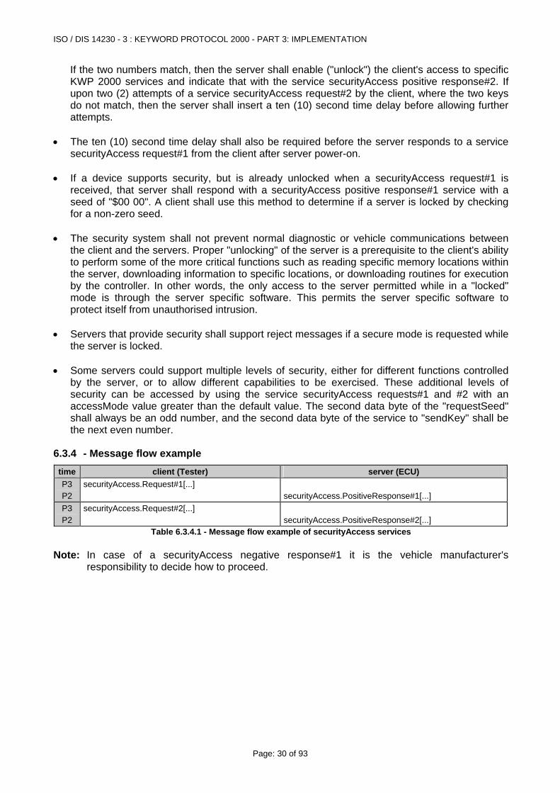
If the two numbers match, then the server shall enable ("unlock") the client's access to specific KWP 2000 services and indicate that with the service securityAccess positive response#2. If upon two (2) attempts of a service securityAccess request#2 by the client, where the two keys do not match, then the server shall insert a ten (10) second time delay before allowing further attempts.
• The ten (10) second time delay shall also be required before the server responds to a service securityAccess request#1 from the client after server power-on.
• If a device supports security, but is already unlocked when a securityAccess request#1 is
received, that server shall respond with a securityAccess positive response#1 service with a seed of "$00 00". A client shall use this method to determine if a server is locked by checking for a non-zero seed.
• The security system shall not prevent normal diagnostic or vehicle communications between
the client and the servers. Proper "unlocking" of the server is a prerequisite to the client's ability to perform some of the more critical functions such as reading specific memory locations within the server, downloading information to specific locations, or downloading routines for execution by the controller. In other words, the only access to the server permitted while in a "locked" mode is through the server specific software. This permits the server specific software to protect itself from unauthorised intrusion.
• Servers that provide security shall support reject messages if a secure mode is requested while
the server is locked. • Some servers could support multiple levels of security, either for different functions controlled
by the server, or to allow different capabilities to be exercised. These additional levels of security can be accessed by using the service securityAccess requests#1 and #2 with an accessMode value greater than the default value. The second data byte of the "requestSeed" shall always be an odd number, and the second data byte of the service to "sendKey" shall be the next even number.
6.3.4 - Message flow example time client (Tester) server (ECU) P3 P2
securityAccess.Request#1[...] securityAccess.PositiveResponse#1[...]
P3 P2
securityAccess.Request#2[...] securityAccess.PositiveResponse#2[...]
Table 6.3.4.1 - Message flow example of securityAccess services Note: In case of a securityAccess negative response#1 it is the vehicle manufacturer's
responsibility to decide how to proceed.
ISO / DIS 14230 - 3 : KEYWORD PROTOCOL 2000 - PART 3: IMPLEMENTATION
Page: 31 of 93
6.4 - TesterPresent service
6.4.1 - Parameter definition
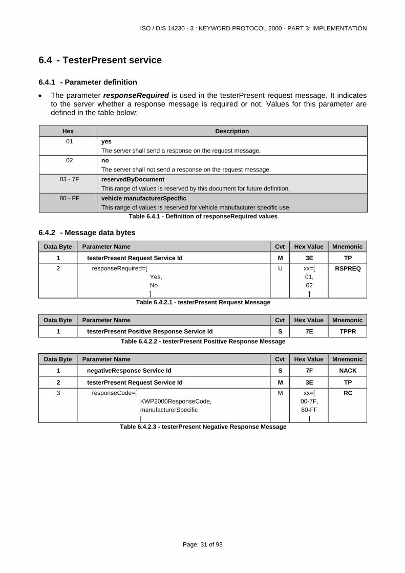
• The parameter responseRequired is used in the testerPresent request message. It indicates to the server whether a response message is required or not. Values for this parameter are defined in the table below:
Hex Description
01 yes The server shall send a response on the request message.
02 no The server shall not send a response on the request message.
03 - 7F reservedByDocument This range of values is reserved by this document for future definition.
80 - FF vehicle manufacturerSpecific This range of values is reserved for vehicle manufacturer specific use.
Table 6.4.1 - Definition of responseRequired values
6.4.2 - Message data bytes
Data Byte Parameter Name Cvt Hex Value Mnemonic
1 testerPresent Request Service Id M 3E TP 2 responseRequired=[
Yes, No ]
U xx=[ 01, 02 ]
RSPREQ
Table 6.4.2.1 - testerPresent Request Message
Data Byte Parameter Name Cvt Hex Value Mnemonic
1 testerPresent Positive Response Service Id S 7E TPPR Table 6.4.2.2 - testerPresent Positive Response Message
Data Byte Parameter Name Cvt Hex Value Mnemonic
1 negativeResponse Service Id S 7F NACK
2 testerPresent Request Service Id M 3E TP 3 responseCode=[
KWP2000ResponseCode, manufacturerSpecific ]
M xx=[ 00-7F, 80-FF
]
RC
Table 6.4.2.3 - testerPresent Negative Response Message
ISO / DIS 14230 - 3 : KEYWORD PROTOCOL 2000 - PART 3: IMPLEMENTATION
Page: 32 of 93
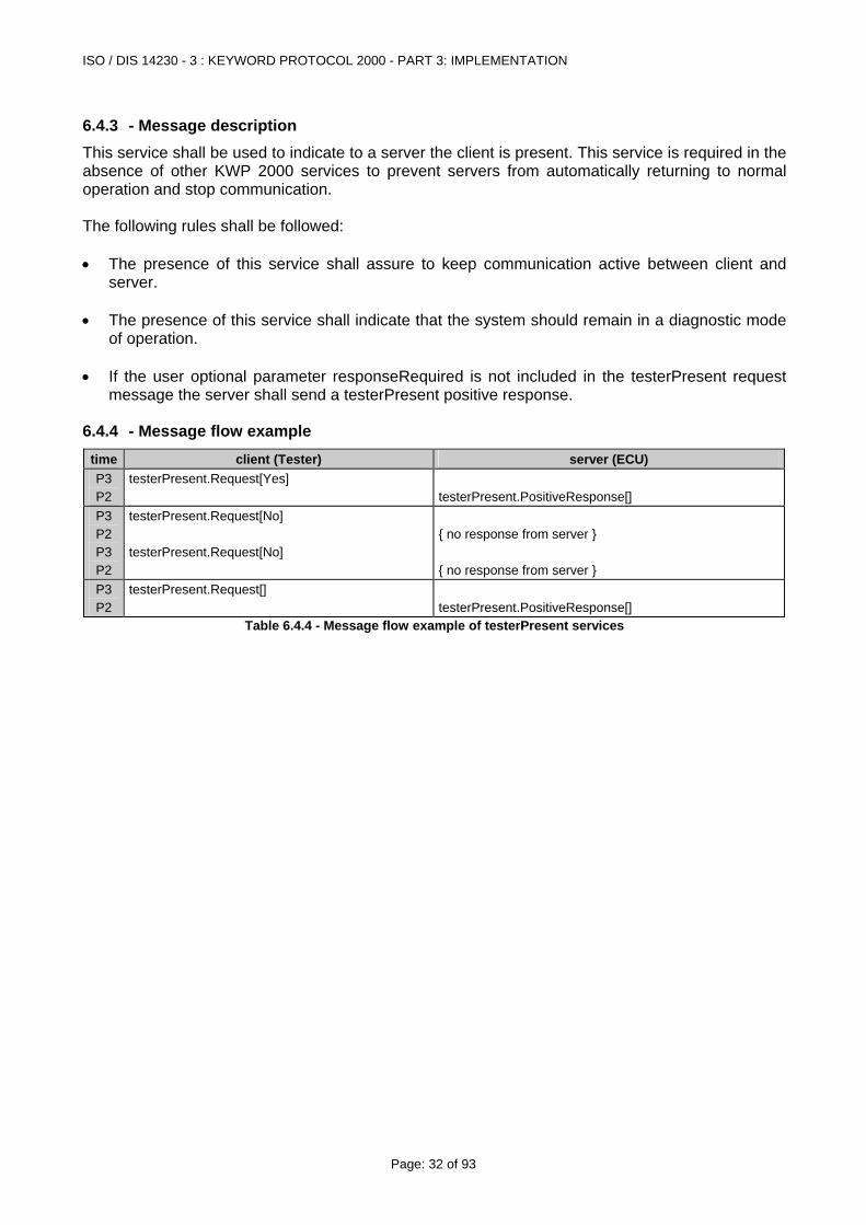
6.4.3 - Message description This service shall be used to indicate to a server the client is present. This service is required in the absence of other KWP 2000 services to prevent servers from automatically returning to normal operation and stop communication. The following rules shall be followed: • The presence of this service shall assure to keep communication active between client and
server. • The presence of this service shall indicate that the system should remain in a diagnostic mode
of operation. • If the user optional parameter responseRequired is not included in the testerPresent request
message the server shall send a testerPresent positive response.
6.4.4 - Message flow example time client (Tester) server (ECU) P3 P2
testerPresent.Request[Yes] testerPresent.PositiveResponse[]
P3 P2 P3 P2
testerPresent.Request[No] testerPresent.Request[No]
{ no response from server } { no response from server }
P3 P2
testerPresent.Request[] testerPresent.PositiveResponse[]
Table 6.4.4 - Message flow example of testerPresent services

ISO / DIS 14230 - 3 : KEYWORD PROTOCOL 2000 - PART 3: IMPLEMENTATION
Page: 33 of 93
6.5 - EcuReset service
6.5.1 - Parameter definition
• The parameter resetMode is used by the ecuReset request message to describe how the server has to perform the reset. Values are defined in the table below:
Hex Description
01 powerOn This value identifies the powerOn resetMode which shall be a simulated powerOn reset which most ECUs perform after ignition OFF/ON cycle. When the ECU performs the reset the client (tester) shall be prepared to re-establish communication.
02 powerOnWhileMaintainingCommunication This value identifies the powerOn resetMode which shall be a simulated powerOn reset which most ECUs perform after ignition OFF/ON cycle. When the ECU performs the reset the server (ECU) shall maintain the communication with the client (tester).
03 - 7F reservedByDocument This range of values is reserved by this document for future definition.
80 - FF manufacturerSpecific This range of values is reserved for vehicle manufacturer specific use.
Table 6.5.1.1 - Definition of resetMode values • The parameter resetStatus is used by the ecuReset positive response message to provide
information about the status of the reset(s). Format and length of this parameter are vehicle manufacturer specific.
Hex Description
xx ... xx resetStatus This parameter shall report resetStatus information. It is the vehicle manufacturer's responsibility to define the type and format of the data value(s).
Table 6.5.1.2 - Definition of resetStatus value
6.5.2 - Message data bytes
Data Byte Parameter Name Cvt Hex Value Mnemonic
1 ecuReset Request Service Id M 11 ECURST2 resetMode=[
powerOn, powerOnWhileMaintainingCommunication, reservedByDocument, manufacturerSpecific ]
U xx=[ 01, 02,
03 - 7F, 80 - FF
]
RSTOPT
Table 6.5.2.1 - ecuReset Request Message
Data Byte Parameter Name Cvt Hex Value Mnemonic
1 ecuReset Positive Response Service Id S 51 ECURSTPR2 : n
resetStatus#1 : resetStatus#m
U : U
xx :
xx
RSTSTAT
Table 6.5.2.2 - ecuReset Positive Response Message
ISO / DIS 14230 - 3 : KEYWORD PROTOCOL 2000 - PART 3: IMPLEMENTATION
Page: 34 of 93
Data Byte Parameter Name Cvt Hex Value Mnemonic
1 negativeResponse Service Id S 7F NACK
2 ecuReset Request Service Id M 11 ECURST3 responseCode=[
KWP2000ResponseCode, manufacturerSpecific ]
M xx=[ 00-7F, 80-FF
]
RC
Table 6.5.2.3 - ecuReset Negative Response Message
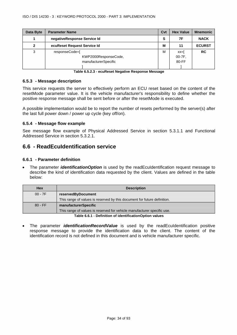
6.5.3 - Message description This service requests the server to effectively perform an ECU reset based on the content of the resetMode parameter value. It is the vehicle manufacturer's responsibility to define whether the positive response message shall be sent before or after the resetMode is executed. A possible implementation would be to report the number of resets performed by the server(s) after the last full power down / power up cycle (key off/on).
6.5.4 - Message flow example See message flow example of Physical Addressed Service in section 5.3.1.1 and Functional Addressed Service in section 5.3.2.1.
6.6 - ReadEcuIdentification service
6.6.1 - Parameter definition
• The parameter identificationOption is used by the readEcuIdentification request message to describe the kind of identification data requested by the client. Values are defined in the table below:
Hex Description
00 - 7F reservedByDocument This range of values is reserved by this document for future definition.
80 - FF manufacturerSpecific This range of values is reserved for vehicle manufacturer specific use.
Table 6.6.1 - Definition of identificationOption values • The parameter identificationRecordValue is used by the readEcuIdentification positive
response message to provide the identification data to the client. The content of the identification record is not defined in this document and is vehicle manufacturer specific.
ISO / DIS 14230 - 3 : KEYWORD PROTOCOL 2000 - PART 3: IMPLEMENTATION
Page: 35 of 93
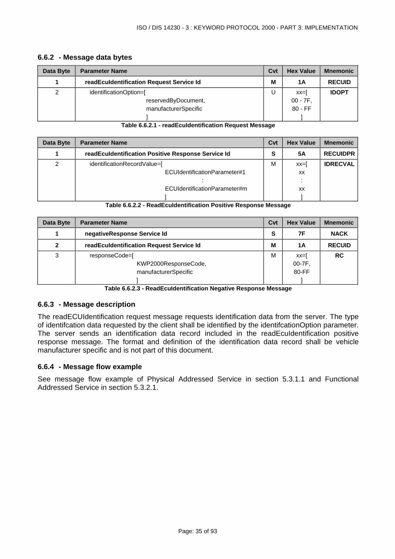
6.6.2 - Message data bytes
Data Byte Parameter Name Cvt Hex Value Mnemonic
1 readEcuIdentification Request Service Id M 1A RECUID 2 identificationOption=[
reservedByDocument, manufacturerSpecific ]
U xx=[ 00 - 7F, 80 - FF
]
IDOPT
Table 6.6.2.1 - readEcuIdentification Request Message
Data Byte Parameter Name Cvt Hex Value Mnemonic
1 readEcuIdentification Positive Response Service Id S 5A RECUIDPR2 identificationRecordValue=[
ECUIdentificationParameter#1 : ECUIdentificationParameter#m ]
M
xx=[ xx :
xx ]
IDRECVAL
Table 6.6.2.2 - ReadEcuIdentification Positive Response Message
Data Byte Parameter Name Cvt Hex Value Mnemonic
1 negativeResponse Service Id S 7F NACK
2 readEcuIdentification Request Service Id M 1A RECUID 3 responseCode=[
KWP2000ResponseCode, manufacturerSpecific ]
M xx=[ 00-7F, 80-FF
]
RC
Table 6.6.2.3 - ReadEcuIdentification Negative Response Message
6.6.3 - Message description The readECUIdentification request message requests identification data from the server. The type of identifcation data requested by the client shall be identified by the identifcationOption parameter. The server sends an identification data record included in the readEcuIdentification positive response message. The format and definition of the identification data record shall be vehicle manufacturer specific and is not part of this document.
6.6.4 - Message flow example See message flow example of Physical Addressed Service in section 5.3.1.1 and Functional Addressed Service in section 5.3.2.1.
ISO / DIS 14230 - 3 : KEYWORD PROTOCOL 2000 - PART 3: IMPLEMENTATION
Page: 36 of 93
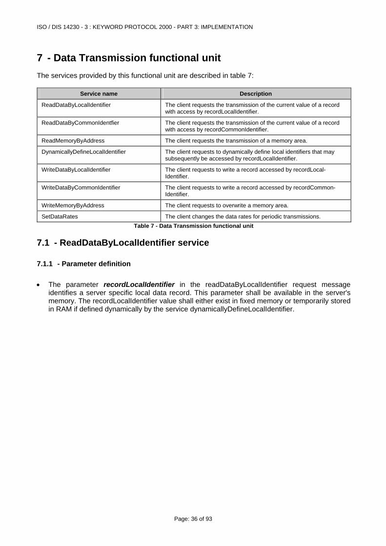
7 - Data Transmission functional unit The services provided by this functional unit are described in table 7:
Service name Description
ReadDataByLocalIdentifier The client requests the transmission of the current value of a record with access by recordLocalIdentifier.
ReadDataByCommonIdentfier The client requests the transmission of the current value of a record with access by recordCommonIdentifier.
ReadMemoryByAddress The client requests the transmission of a memory area.
DynamicallyDefineLocalIdentifier The client requests to dynamically define local identifiers that may subsequently be accessed by recordLocalIdentifier.
WriteDataByLocalIdentifier The client requests to write a record accessed by recordLocal-Identifier.
WriteDataByCommonIdentifier The client requests to write a record accessed by recordCommon-Identifier.
WriteMemoryByAddress The client requests to overwrite a memory area.
SetDataRates The client changes the data rates for periodic transmissions. Table 7 - Data Transmission functional unit
7.1 - ReadDataByLocalIdentifier service
7.1.1 - Parameter definition • The parameter recordLocalIdentifier in the readDataByLocalIdentifier request message
identifies a server specific local data record. This parameter shall be available in the server's memory. The recordLocalIdentifier value shall either exist in fixed memory or temporarily stored in RAM if defined dynamically by the service dynamicallyDefineLocalIdentifier.
ISO / DIS 14230 - 3 : KEYWORD PROTOCOL 2000 - PART 3: IMPLEMENTATION
Page: 37 of 93
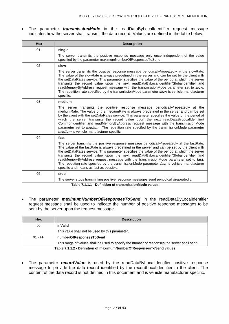
• The parameter transmissionMode in the readDataByLocalIdentifier request message indicates how the server shall transmit the data record. Values are defined in the table below:
Hex Description
01 single The server transmits the positive response message only once independent of the value specified by the parameter maximumNumberOfResponsesToSend.
02 slow The server transmits the positive response message periodically/repeatedly at the slowRate. The value of the slowRate is always predefined in the server and can be set by the client with the setDataRates service. This parameter specifies the value of the period at which the server transmits the record value upon the next readDataByLocalIdentifier/GlobalIdentifier and readMemoryByAddress request message with the transmissionMode parameter set to slow. The repetition rate specified by the transmissionMode parameter slow is vehicle manufacturer specific.
03 medium The server transmits the positive response message periodically/repeatedly at the mediumRate. The value of the mediumRate is always predefined in the server and can be set by the client with the setDataRates service. This parameter specifies the value of the period at which the server transmits the record value upon the next readDataByLocalIdentifier/ CommonIdentifier and readMemoryByAddress request message with the transmissionMode parameter set to medium. The repetition rate specifed by the transmissionMode parameter medium is vehicle manufacturer specific.
04 fast The server transmits the positive response message periodically/repeatedly at the fastRate. The value of the fastRate is always predefined in the server and can be set by the client with the setDataRates service. This parameter specifies the value of the period at which the server transmits the record value upon the next readDataByLocalIdentifier/GlobalIdentifier and readMemoryByAddress request message with the transmissionMode parameter set to fast. The repetition rate specifed by the transmissionMode parameter fast is vehicle manufacturer specific and means as fast as possible.
05 stop The server stops transmitting positive response messages send periodically/repeatedly.
Table 7.1.1.1 - Definition of transmissionMode values • The parameter maximumNumberOfResponsesToSend in the readDataByLocalIdentifier
request message shall be used to indicate the number of positive response messages to be sent by the server upon the request message.
Hex Description
00 inValid This value shall not be used by this parameter.
01 - FF numberOfResponsesToSend This range of values shall be used to specify the number of responses the server shall send.
Table 7.1.1.2 - Definition of maximumNumberOfResponsesToSend values • The parameter recordValue is used by the readDataByLocalIdentifier positive response
message to provide the data record identified by the recordLocalIdentifier to the client. The content of the data record is not defined in this document and is vehicle manufacturer specific.
ISO / DIS 14230 - 3 : KEYWORD PROTOCOL 2000 - PART 3: IMPLEMENTATION
Page: 38 of 93
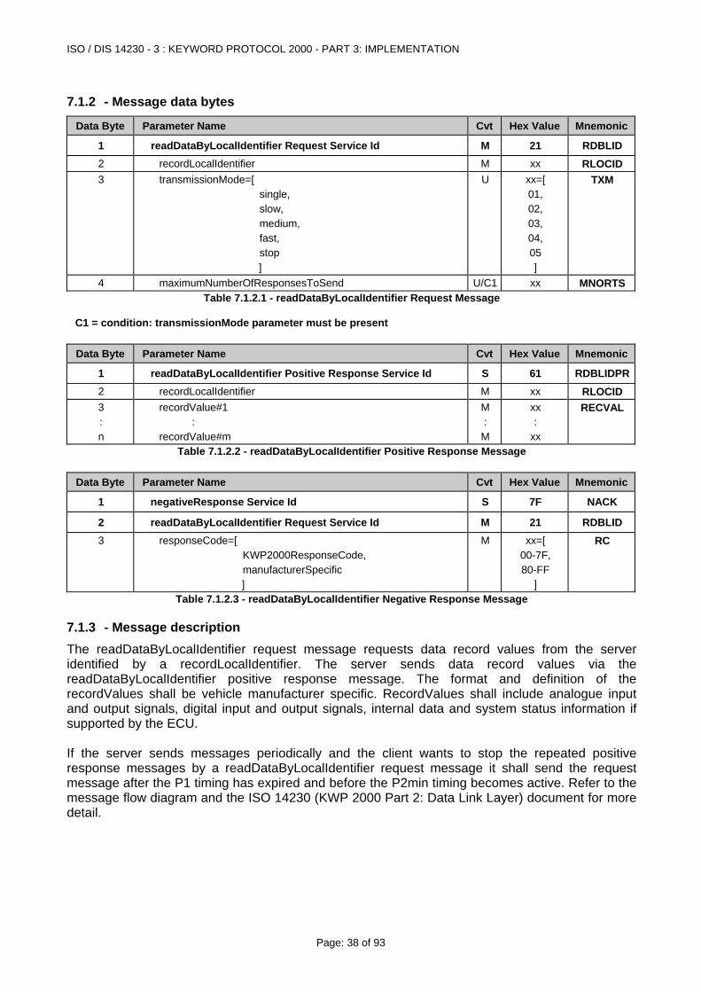
7.1.2 - Message data bytes
Data Byte Parameter Name Cvt Hex Value Mnemonic
1 readDataByLocalIdentifier Request Service Id M 21 RDBLID 2 recordLocalIdentifier M xx RLOCID 3 transmissionMode=[
single, slow, medium, fast, stop ]
U xx=[ 01, 02, 03, 04, 05 ]
TXM
4 maximumNumberOfResponsesToSend U/C1 xx MNORTSTable 7.1.2.1 - readDataByLocalIdentifier Request Message
C1 = condition: transmissionMode parameter must be present
Data Byte Parameter Name Cvt Hex Value Mnemonic
1 readDataByLocalIdentifier Positive Response Service Id S 61 RDBLIDPR2 recordLocalIdentifier M xx RLOCID 3 : n
recordValue#1 : recordValue#m
M : M
xx :
xx
RECVAL
Table 7.1.2.2 - readDataByLocalIdentifier Positive Response Message
Data Byte Parameter Name Cvt Hex Value Mnemonic
1 negativeResponse Service Id S 7F NACK
2 readDataByLocalIdentifier Request Service Id M 21 RDBLID 3 responseCode=[
KWP2000ResponseCode, manufacturerSpecific ]
M xx=[ 00-7F, 80-FF
]
RC
Table 7.1.2.3 - readDataByLocalIdentifier Negative Response Message
7.1.3 - Message description The readDataByLocalIdentifier request message requests data record values from the server identified by a recordLocalIdentifier. The server sends data record values via the readDataByLocalIdentifier positive response message. The format and definition of the recordValues shall be vehicle manufacturer specific. RecordValues shall include analogue input and output signals, digital input and output signals, internal data and system status information if supported by the ECU. If the server sends messages periodically and the client wants to stop the repeated positive response messages by a readDataByLocalIdentifier request message it shall send the request message after the P1 timing has expired and before the P2min timing becomes active. Refer to the message flow diagram and the ISO 14230 (KWP 2000 Part 2: Data Link Layer) document for more detail.
ISO / DIS 14230 - 3 : KEYWORD PROTOCOL 2000 - PART 3: IMPLEMENTATION
Page: 39 of 93
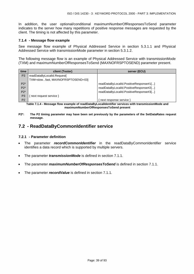
In addition, the user optional/conditional maximumNumberOfResponsesToSend parameter indicates to the server how many repetitions of positive response messages are requested by the client. The timing is not affected by this parameter.
7.1.4 - Message flow example See message flow example of Physical Addressed Service in section 5.3.1.1 and Physical Addressed Service with transmissionMode parameter in section 5.3.1.2. The following message flow is an example of Physical Addressed Service with transmissionMode (TXM) and maximumNumberOfResponsesToSend (MAXNOFRSPTOSEND) parameter present.
time client (Tester) server (ECU) P3
P2* P2* P2* P3 P2
readDataByLocalId.Request[ TXM=slow...fast, MAXNOFRSPTOSEND=03] { next request service }
readDataByLocalId.PositiveResponse#1[...] readDataByLocalId.PositiveResponse#2[...] readDataByLocalId.PositiveResponse#3[...] { next response service }
Table 7.1.4 - Message flow example of readDataByLocalIdentifier services with transmissionMode and maximumNumberOfResponsesToSend present
P2*: The P2 timing parameter may have been set previously by the parameters of the SetDataRates request
message.
7.2 - ReadDataByCommonIdentifier service
7.2.1 - Parameter definition
• The parameter recordCommonIdentifier in the readDataByCommonIdentifier service identifies a data record which is supported by multiple servers.
• The parameter transmissionMode is defined in section 7.1.1. • The parameter maximumNumberOfResponsesToSend is defined in section 7.1.1. • The parameter recordValue is defined in section 7.1.1.
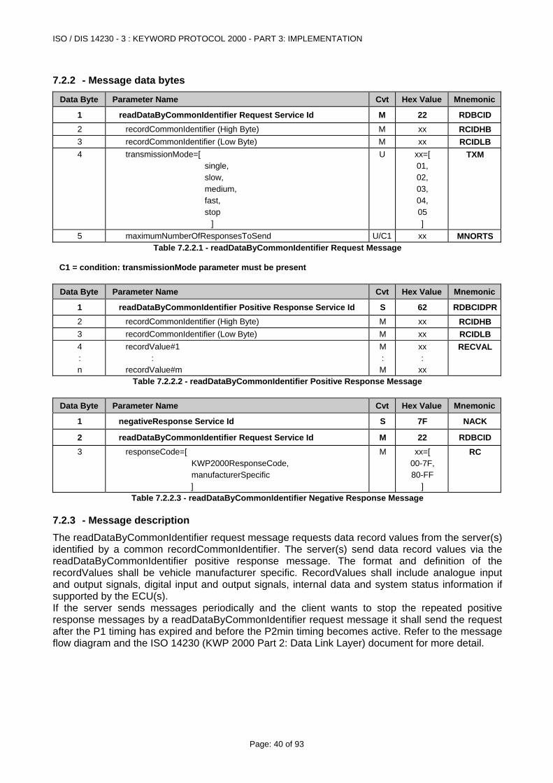
ISO / DIS 14230 - 3 : KEYWORD PROTOCOL 2000 - PART 3: IMPLEMENTATION
Page: 40 of 93
7.2.2 - Message data bytes
Data Byte Parameter Name Cvt Hex Value Mnemonic
1 readDataByCommonIdentifier Request Service Id M 22 RDBCID 2 recordCommonIdentifier (High Byte) M xx RCIDHB 3 recordCommonIdentifier (Low Byte) M xx RCIDLB 4 transmissionMode=[
single, slow, medium, fast, stop
]
U xx=[ 01, 02, 03, 04, 05 ]
TXM
5 maximumNumberOfResponsesToSend U/C1 xx MNORTSTable 7.2.2.1 - readDataByCommonIdentifier Request Message
C1 = condition: transmissionMode parameter must be present
Data Byte Parameter Name Cvt Hex Value Mnemonic
1 readDataByCommonIdentifier Positive Response Service Id S 62 RDBCIDPR2 recordCommonIdentifier (High Byte) M xx RCIDHB 3 recordCommonIdentifier (Low Byte) M xx RCIDLB 4 : n
recordValue#1 : recordValue#m
M : M
xx :
xx
RECVAL
Table 7.2.2.2 - readDataByCommonIdentifier Positive Response Message
Data Byte Parameter Name Cvt Hex Value Mnemonic
1 negativeResponse Service Id S 7F NACK
2 readDataByCommonIdentifier Request Service Id M 22 RDBCID 3 responseCode=[
KWP2000ResponseCode, manufacturerSpecific ]
M xx=[ 00-7F, 80-FF
]
RC
Table 7.2.2.3 - readDataByCommonIdentifier Negative Response Message
7.2.3 - Message description The readDataByCommonIdentifier request message requests data record values from the server(s) identified by a common recordCommonIdentifier. The server(s) send data record values via the readDataByCommonIdentifier positive response message. The format and definition of the recordValues shall be vehicle manufacturer specific. RecordValues shall include analogue input and output signals, digital input and output signals, internal data and system status information if supported by the ECU(s). If the server sends messages periodically and the client wants to stop the repeated positive response messages by a readDataByCommonIdentifier request message it shall send the request after the P1 timing has expired and before the P2min timing becomes active. Refer to the message flow diagram and the ISO 14230 (KWP 2000 Part 2: Data Link Layer) document for more detail.
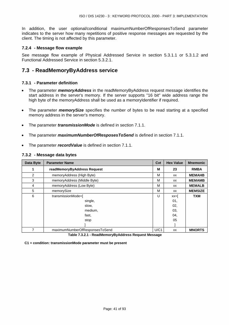
ISO / DIS 14230 - 3 : KEYWORD PROTOCOL 2000 - PART 3: IMPLEMENTATION
Page: 41 of 93
In addition, the user optional/conditional maximumNumberOfResponsesToSend parameter indicates to the server how many repetitions of positive response messages are requested by the client. The timing is not affected by this parameter.
7.2.4 - Message flow example See message flow example of Physical Addressed Service in section 5.3.1.1 or 5.3.1.2 and Functional Addressed Service in section 5.3.2.1.
7.3 - ReadMemoryByAddress service
7.3.1 - Parameter definition
• The parameter memoryAddress in the readMemoryByAddress request message identifies the start address in the server's memory. If the server supports "16 bit" wide address range the high byte of the memoryAddress shall be used as a memoryIdentifier if required.
• The parameter memorySize specifies the number of bytes to be read starting at a specified
memory address in the server's memory. • The parameter transmissionMode is defined in section 7.1.1. • The parameter maximumNumberOfResposesToSend is defined in section 7.1.1. • The parameter recordValue is defined in section 7.1.1.
7.3.2 - Message data bytes
Data Byte Parameter Name Cvt Hex Value Mnemonic
1 readMemoryByAddress Request M 23 RMBA 2 memoryAddress (High Byte) M xx MEMAHB3 memoryAddress (Middle Byte) M xx MEMAMB4 memoryAddress (Low Byte) M xx MEMALB5 memorySize M xx MEMSIZE6 transmissionMode=[
single, slow, medium, fast, stop ]
U xx=[ 01, 02, 03, 04, 05 ]
TXM
7 maximumNumberOfResponsesToSend U/C1 xx MNORTSTable 7.3.2.1 - ReadMemoryByAddress Request Message
C1 = condition: transmissionMode parameter must be present
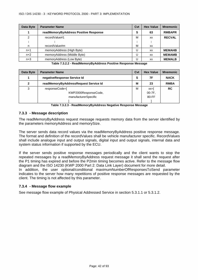
ISO / DIS 14230 - 3 : KEYWORD PROTOCOL 2000 - PART 3: IMPLEMENTATION
Page: 42 of 93
Data Byte Parameter Name Cvt Hex Value Mnemonic
1 readMemoryByAddress Positive Response S 63 RMBAPR2 : n
recordValue#1 : recordValue#m
M : M
xx :
xx
RECVAL
n+1 memoryAddress (High Byte) U xx MEMAHBn+2 memoryAddress (Middle Byte) U xx MEMAMBn+3 memoryAddress (Low Byte) U xx MEMALB
Table 7.3.2.2 - ReadMemoryByAddress Positive Response Message
Data Byte Parameter Name Cvt Hex Value Mnemonic
1 negativeResponse Service Id S 7F NACK
2 readMemoryByAddressRequest Service Id M 23 RMBA 3 responseCode=[
KWP2000ResponseCode, manufacturerSpecific ]
M xx=[ 00-7F, 80-FF
]
RC
Table 7.3.2.3 - ReadMemoryByAddress Negative Response Message
7.3.3 - Message description The readMemoryByAddress request message requests memory data from the server identified by the parameters memoryAddress and memorySize. The server sends data record values via the readMemoryByAddress positive response message. The format and definition of the recordValues shall be vehicle manufacturer specific. RecordValues shall include analogue input and output signals, digital input and output signals, internal data and system status information if supported by the ECU. If the server sends positive response messages periodically and the client wants to stop the repeated messages by a readMemoryByAddress request message it shall send the request after the P1 timing has expired and before the P2min timing becomes active. Refer to the message flow diagram and the ISO 14230 (KWP 2000 Part 2: Data Link Layer) document for more detail. In addition, the user optional/conditional maximumNumberOfResponsesToSend parameter indicates to the server how many repetitions of positive response messages are requested by the client. The timing is not affected by this parameter.
7.3.4 - Message flow example See message flow example of Physical Addressed Service in section 5.3.1.1 or 5.3.1.2.
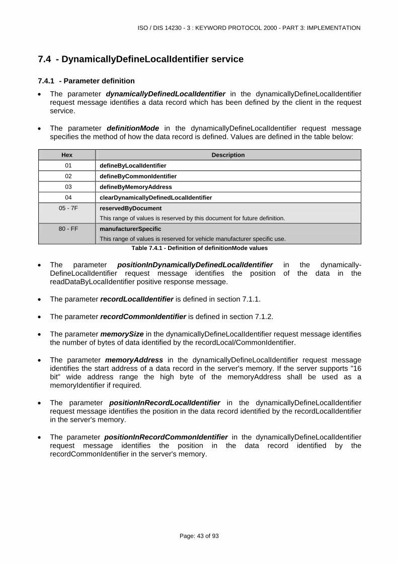
ISO / DIS 14230 - 3 : KEYWORD PROTOCOL 2000 - PART 3: IMPLEMENTATION
Page: 43 of 93
7.4 - DynamicallyDefineLocalIdentifier service
7.4.1 - Parameter definition
• The parameter dynamicallyDefinedLocalIdentifier in the dynamicallyDefineLocalIdentifier request message identifies a data record which has been defined by the client in the request service.
• The parameter definitionMode in the dynamicallyDefineLocalIdentifier request message
specifies the method of how the data record is defined. Values are defined in the table below:
Hex Description
01 defineByLocalIdentifier
02 defineByCommonIdentifier
03 defineByMemoryAddress
04 clearDynamicallyDefinedLocalIdentifier
05 - 7F reservedByDocument This range of values is reserved by this document for future definition.
80 - FF manufacturerSpecific This range of values is reserved for vehicle manufacturer specific use.
Table 7.4.1 - Definition of definitionMode values • The parameter positionInDynamicallyDefinedLocalIdentifier in the dynamically-
DefineLocalIdentifier request message identifies the position of the data in the readDataByLocalIdentifier positive response message.
• The parameter recordLocalIdentifier is defined in section 7.1.1. • The parameter recordCommonIdentifier is defined in section 7.1.2. • The parameter memorySize in the dynamicallyDefineLocalIdentifier request message identifies
the number of bytes of data identified by the recordLocal/CommonIdentifier. • The parameter memoryAddress in the dynamicallyDefineLocalIdentifier request message
identifies the start address of a data record in the server's memory. If the server supports "16 bit" wide address range the high byte of the memoryAddress shall be used as a memoryIdentifier if required.
• The parameter positionInRecordLocalIdentifier in the dynamicallyDefineLocalIdentifier
request message identifies the position in the data record identified by the recordLocalIdentifier in the server's memory.
• The parameter positionInRecordCommonIdentifier in the dynamicallyDefineLocalIdentifier
request message identifies the position in the data record identified by the recordCommonIdentifier in the server's memory.
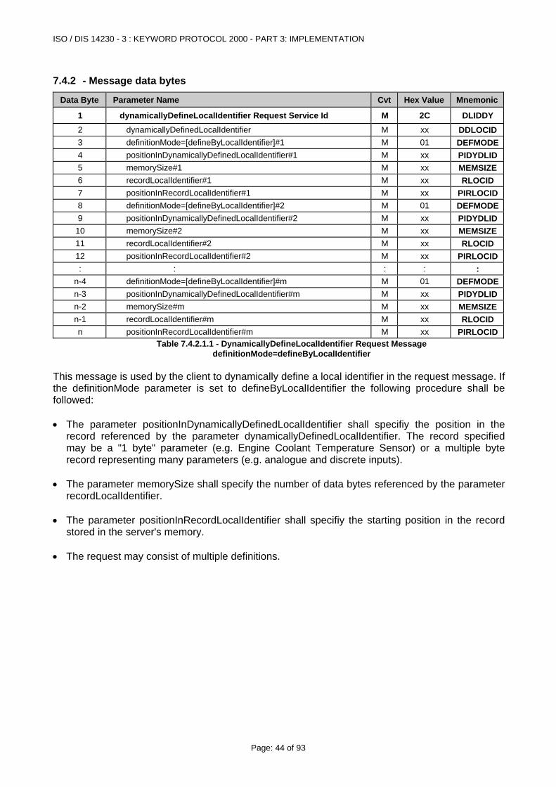
ISO / DIS 14230 - 3 : KEYWORD PROTOCOL 2000 - PART 3: IMPLEMENTATION
Page: 44 of 93
7.4.2 - Message data bytes
Data Byte Parameter Name Cvt Hex Value Mnemonic
1 dynamicallyDefineLocalIdentifier Request Service Id M 2C DLIDDY 2 dynamicallyDefinedLocalIdentifier M xx DDLOCID3 definitionMode=[defineByLocalIdentifier]#1 M 01 DEFMODE4 positionInDynamicallyDefinedLocalIdentifier#1 M xx PIDYDLID5 memorySize#1 M xx MEMSIZE6 recordLocalIdentifier#1 M xx RLOCID 7 positionInRecordLocalIdentifier#1 M xx PIRLOCID8 definitionMode=[defineByLocalIdentifier]#2 M 01 DEFMODE9 positionInDynamicallyDefinedLocalIdentifier#2 M xx PIDYDLID
10 memorySize#2 M xx MEMSIZE11 recordLocalIdentifier#2 M xx RLOCID 12 positionInRecordLocalIdentifier#2 M xx PIRLOCID: : : : :
n-4 definitionMode=[defineByLocalIdentifier]#m M 01 DEFMODEn-3 positionInDynamicallyDefinedLocalIdentifier#m M xx PIDYDLIDn-2 memorySize#m M xx MEMSIZEn-1 recordLocalIdentifier#m M xx RLOCID n positionInRecordLocalIdentifier#m M xx PIRLOCID
Table 7.4.2.1.1 - DynamicallyDefineLocalIdentifier Request Message definitionMode=defineByLocalIdentifier
This message is used by the client to dynamically define a local identifier in the request message. If the definitionMode parameter is set to defineByLocalIdentifier the following procedure shall be followed: • The parameter positionInDynamicallyDefinedLocalIdentifier shall specifiy the position in the
record referenced by the parameter dynamicallyDefinedLocalIdentifier. The record specified may be a "1 byte" parameter (e.g. Engine Coolant Temperature Sensor) or a multiple byte record representing many parameters (e.g. analogue and discrete inputs).
• The parameter memorySize shall specify the number of data bytes referenced by the parameter
recordLocalIdentifier. • The parameter positionInRecordLocalIdentifier shall specifiy the starting position in the record
stored in the server's memory. • The request may consist of multiple definitions.
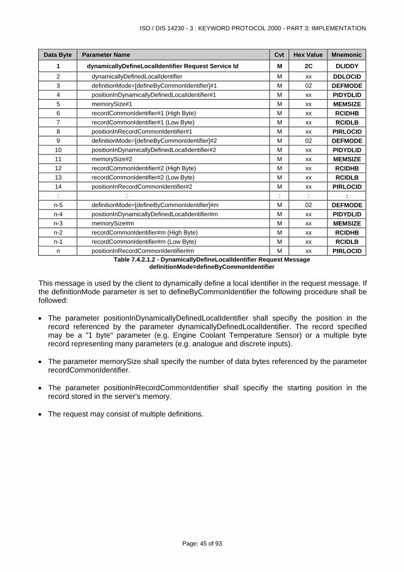
ISO / DIS 14230 - 3 : KEYWORD PROTOCOL 2000 - PART 3: IMPLEMENTATION
Page: 45 of 93
Data Byte Parameter Name Cvt Hex Value Mnemonic
1 dynamicallyDefineLocalIdentifier Request Service Id M 2C DLIDDY 2 dynamicallyDefinedLocalIdentifier M xx DDLOCID3 definitionMode=[defineByCommonIdentifier]#1 M 02 DEFMODE4 positionInDynamicallyDefinedLocalIdentifier#1 M xx PIDYDLID5 memorySize#1 M xx MEMSIZE6 recordCommonIdentifier#1 (High Byte) M xx RCIDHB 7 recordCommonIdentifier#1 (Low Byte) M xx RCIDLB 8 positionInRecordCommonIdentifier#1 M xx PIRLOCID9 definitionMode=[defineByCommonIdentifier]#2 M 02 DEFMODE
10 positionInDynamicallyDefinedLocalIdentifier#2 M xx PIDYDLID11 memorySize#2 M xx MEMSIZE12 recordCommonIdentifier#2 (High Byte) M xx RCIDHB 13 recordCommonIdentifier#2 (Low Byte) M xx RCIDLB 14 positionInRecordCommonIdentifier#2 M xx PIRLOCID: : : : :
n-5 definitionMode=[defineByCommonIdentifier]#m M 02 DEFMODEn-4 positionInDynamicallyDefinedLocalIdentifier#m M xx PIDYDLIDn-3 memorySize#m M xx MEMSIZEn-2 recordCommonIdentifier#m (High Byte) M xx RCIDHB n-1 recordCommonIdentifier#m (Low Byte) M xx RCIDLB n positionInRecordCommonIdentifier#m M xx PIRLOCID
Table 7.4.2.1.2 - DynamicallyDefineLocalIdentifier Request Message definitionMode=defineByCommonIdentifier
This message is used by the client to dynamically define a local identifier in the request message. If the definitionMode parameter is set to defineByCommonIdentifier the following procedure shall be followed: • The parameter positionInDynamicallyDefinedLocalIdentifier shall specifiy the position in the
record referenced by the parameter dynamicallyDefinedLocalIdentifier. The record specified may be a "1 byte" parameter (e.g. Engine Coolant Temperature Sensor) or a multiple byte record representing many parameters (e.g. analogue and discrete inputs).
• The parameter memorySize shall specify the number of data bytes referenced by the parameter
recordCommonIdentifier. • The parameter positionInRecordCommonIdentifier shall specifiy the starting position in the
record stored in the server's memory. • The request may consist of multiple definitions.
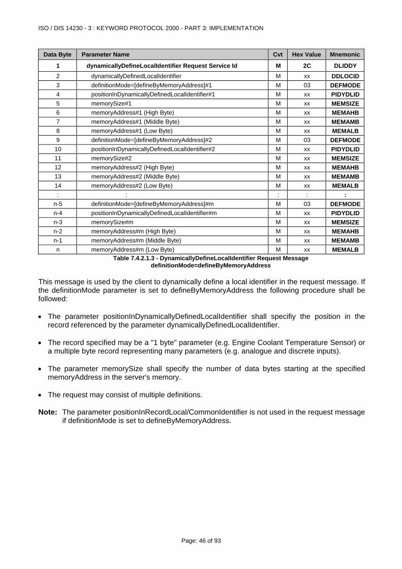
ISO / DIS 14230 - 3 : KEYWORD PROTOCOL 2000 - PART 3: IMPLEMENTATION
Page: 46 of 93
Data Byte Parameter Name Cvt Hex Value Mnemonic
1 dynamicallyDefineLocalIdentifier Request Service Id M 2C DLIDDY 2 dynamicallyDefinedLocalIdentifier M xx DDLOCID3 definitionMode=[defineByMemoryAddress]#1 M 03 DEFMODE4 positionInDynamicallyDefinedLocalIdentifier#1 M xx PIDYDLID5 memorySize#1 M xx MEMSIZE6 memoryAddress#1 (High Byte) M xx MEMAHB7 memoryAddress#1 (Middle Byte) M xx MEMAMB8 memoryAddress#1 (Low Byte) M xx MEMALB9 definitionMode=[defineByMemoryAddress]#2 M 03 DEFMODE
10 positionInDynamicallyDefinedLocalIdentifier#2 M xx PIDYDLID11 memorySize#2 M xx MEMSIZE12 memoryAddress#2 (High Byte) M xx MEMAHB13 memoryAddress#2 (Middle Byte) M xx MEMAMB14 memoryAddress#2 (Low Byte) M xx MEMALB: : : : :
n-5 definitionMode=[defineByMemoryAddress]#m M 03 DEFMODEn-4 positionInDynamicallyDefinedLocalIdentifier#m M xx PIDYDLIDn-3 memorySize#m M xx MEMSIZEn-2 memoryAddress#m (High Byte) M xx MEMAHBn-1 memoryAddress#m (Middle Byte) M xx MEMAMBn memoryAddress#m (Low Byte) M xx MEMALB
Table 7.4.2.1.3 - DynamicallyDefineLocalIdentifier Request Message definitionMode=defineByMemoryAddress
This message is used by the client to dynamically define a local identifier in the request message. If the definitionMode parameter is set to defineByMemoryAddress the following procedure shall be followed: • The parameter positionInDynamicallyDefinedLocalIdentifier shall specifiy the position in the
record referenced by the parameter dynamicallyDefinedLocalIdentifier. • The record specified may be a "1 byte" parameter (e.g. Engine Coolant Temperature Sensor) or
a multiple byte record representing many parameters (e.g. analogue and discrete inputs). • The parameter memorySize shall specify the number of data bytes starting at the specified
memoryAddress in the server's memory. • The request may consist of multiple definitions. Note: The parameter positionInRecordLocal/CommonIdentifier is not used in the request message
if definitionMode is set to defineByMemoryAddress.
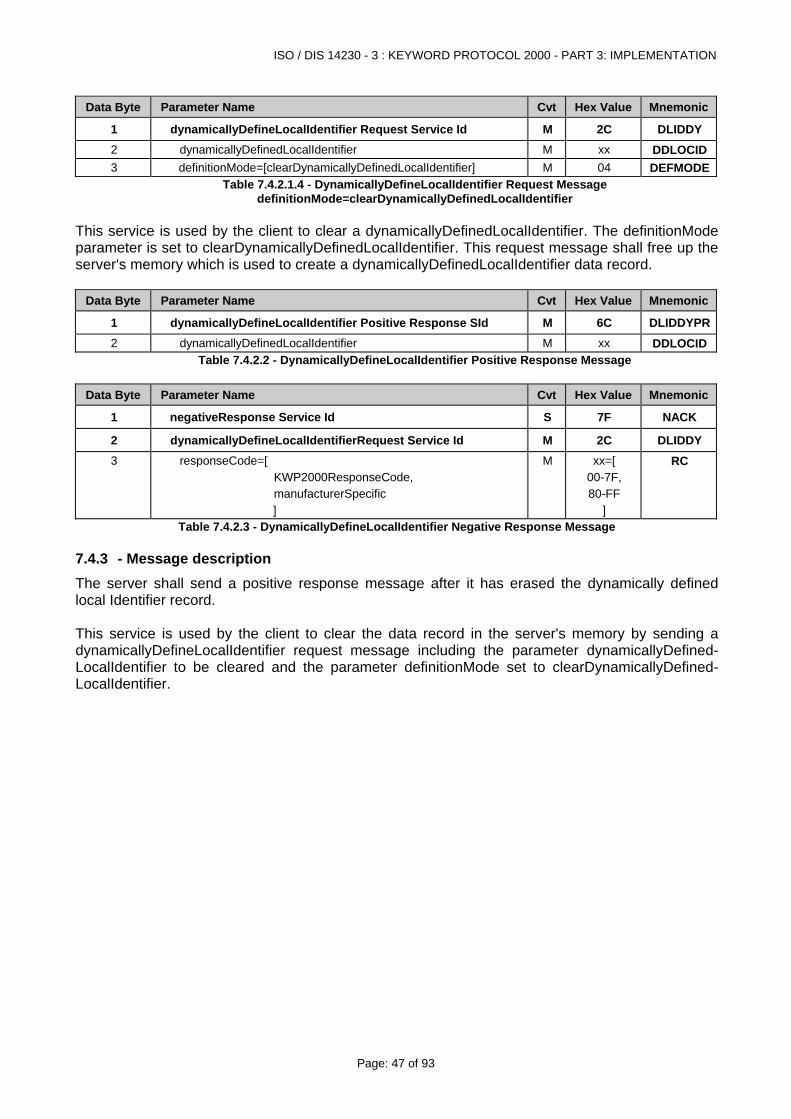
ISO / DIS 14230 - 3 : KEYWORD PROTOCOL 2000 - PART 3: IMPLEMENTATION
Page: 47 of 93
Data Byte Parameter Name Cvt Hex Value Mnemonic
1 dynamicallyDefineLocalIdentifier Request Service Id M 2C DLIDDY 2 dynamicallyDefinedLocalIdentifier M xx DDLOCID3 definitionMode=[clearDynamicallyDefinedLocalIdentifier] M 04 DEFMODE
Table 7.4.2.1.4 - DynamicallyDefineLocalIdentifier Request Message definitionMode=clearDynamicallyDefinedLocalIdentifier
This service is used by the client to clear a dynamicallyDefinedLocalIdentifier. The definitionMode parameter is set to clearDynamicallyDefinedLocalIdentifier. This request message shall free up the server's memory which is used to create a dynamicallyDefinedLocalIdentifier data record.
Data Byte Parameter Name Cvt Hex Value Mnemonic
1 dynamicallyDefineLocalIdentifier Positive Response SId M 6C DLIDDYPR2 dynamicallyDefinedLocalIdentifier M xx DDLOCID
Table 7.4.2.2 - DynamicallyDefineLocalIdentifier Positive Response Message
Data Byte Parameter Name Cvt Hex Value Mnemonic
1 negativeResponse Service Id S 7F NACK
2 dynamicallyDefineLocalIdentifierRequest Service Id M 2C DLIDDY 3 responseCode=[
KWP2000ResponseCode, manufacturerSpecific ]
M xx=[ 00-7F, 80-FF
]
RC
Table 7.4.2.3 - DynamicallyDefineLocalIdentifier Negative Response Message
7.4.3 - Message description The server shall send a positive response message after it has erased the dynamically defined local Identifier record. This service is used by the client to clear the data record in the server's memory by sending a dynamicallyDefineLocalIdentifier request message including the parameter dynamicallyDefined-LocalIdentifier to be cleared and the parameter definitionMode set to clearDynamicallyDefined-LocalIdentifier.
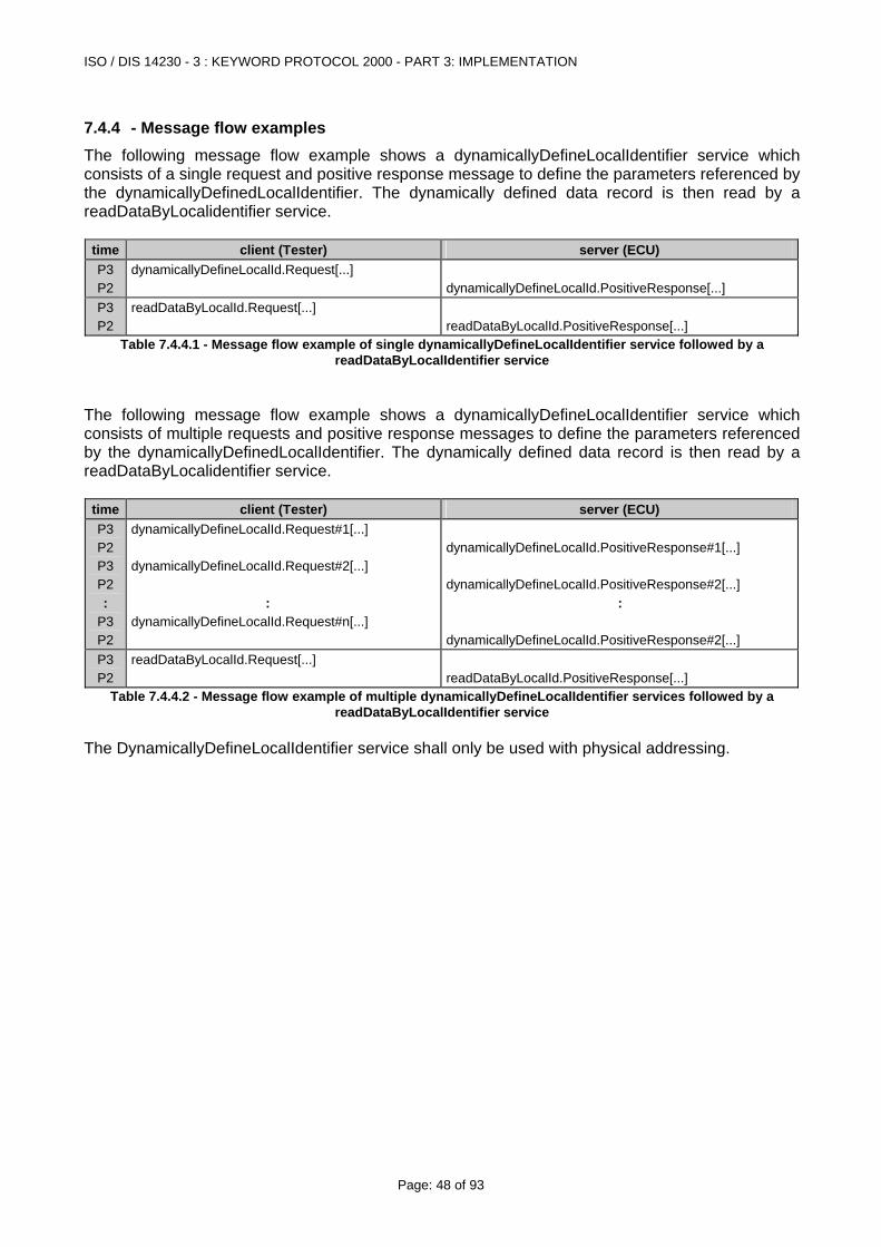
ISO / DIS 14230 - 3 : KEYWORD PROTOCOL 2000 - PART 3: IMPLEMENTATION
Page: 48 of 93
7.4.4 - Message flow examples The following message flow example shows a dynamicallyDefineLocalIdentifier service which consists of a single request and positive response message to define the parameters referenced by the dynamicallyDefinedLocalIdentifier. The dynamically defined data record is then read by a readDataByLocalidentifier service.
time client (Tester) server (ECU) P3 P2
dynamicallyDefineLocalId.Request[...]
dynamicallyDefineLocalId.PositiveResponse[...]
P3 P2
readDataByLocalId.Request[...]
readDataByLocalId.PositiveResponse[...]
Table 7.4.4.1 - Message flow example of single dynamicallyDefineLocalIdentifier service followed by a readDataByLocalIdentifier service
The following message flow example shows a dynamicallyDefineLocalIdentifier service which consists of multiple requests and positive response messages to define the parameters referenced by the dynamicallyDefinedLocalIdentifier. The dynamically defined data record is then read by a readDataByLocalidentifier service.
time client (Tester) server (ECU) P3 P2 P3 P2 :
P3 P2
dynamicallyDefineLocalId.Request#1[...] dynamicallyDefineLocalId.Request#2[...] : dynamicallyDefineLocalId.Request#n[...]
dynamicallyDefineLocalId.PositiveResponse#1[...] dynamicallyDefineLocalId.PositiveResponse#2[...] : dynamicallyDefineLocalId.PositiveResponse#2[...]
P3 P2
readDataByLocalId.Request[...] readDataByLocalId.PositiveResponse[...]
Table 7.4.4.2 - Message flow example of multiple dynamicallyDefineLocalIdentifier services followed by a readDataByLocalIdentifier service
The DynamicallyDefineLocalIdentifier service shall only be used with physical addressing.
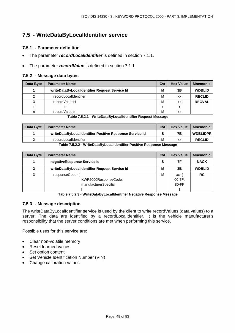
ISO / DIS 14230 - 3 : KEYWORD PROTOCOL 2000 - PART 3: IMPLEMENTATION
Page: 49 of 93
7.5 - WriteDataByLocalIdentifier service
7.5.1 - Parameter definition
• The parameter recordLocalIdentifier is defined in section 7.1.1. • The parameter recordValue is defined in section 7.1.1.
7.5.2 - Message data bytes
Data Byte Parameter Name Cvt Hex Value Mnemonic
1 writeDataByLocalIdentifier Request Service Id M 3B WDBLID 2 recordLocalIdentifier M xx RECLID 3 : n
recordValue#1 : recordValue#m
M : M
xx :
xx
RECVAL
Table 7.5.2.1 - WriteDataByLocalIdentifier Request Message
Data Byte Parameter Name Cvt Hex Value Mnemonic
1 writeDataByLocalIdentifier Positive Response Service Id S 7B WDBLIDPR2 recordLocalIdentifier M xx RECLID
Table 7.5.2.2 - WriteDataByLocalIdentifier Positive Response Message
Data Byte Parameter Name Cvt Hex Value Mnemonic
1 negativeResponse Service Id S 7F NACK
2 writeDataByLocalIdentifier Request Service Id M 3B WDBLID 3 responseCode=[
KWP2000ResponseCode, manufacturerSpecific ]
M xx=[ 00-7F, 80-FF
]
RC
Table 7.5.2.3 - WriteDataByLocalIdentifier Negative Response Message
7.5.3 - Message description The writeDataByLocalIdentifier service is used by the client to write recordValues (data values) to a server. The data are identified by a recordLocalIdentifier. It is the vehicle manufacturer's responsibility that the server conditions are met when performing this service. Possible uses for this service are: • Clear non-volatile memory • Reset learned values • Set option content • Set Vehicle Identification Number (VIN) • Change calibration values
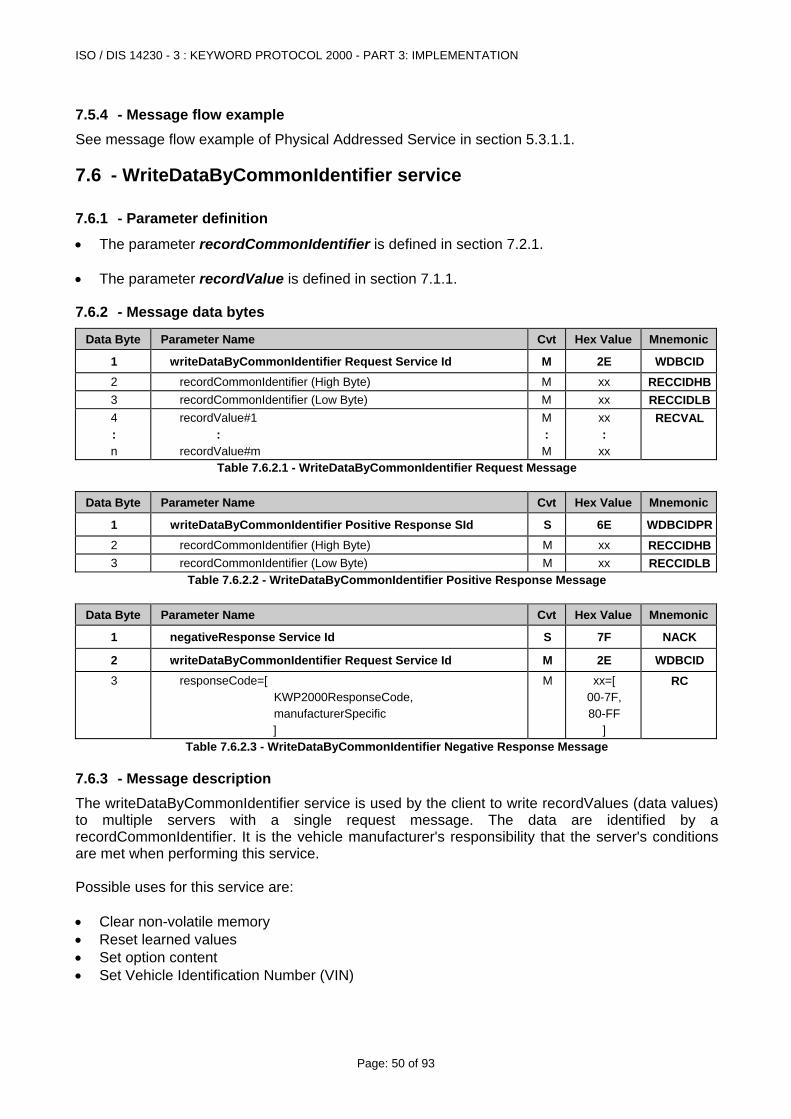
ISO / DIS 14230 - 3 : KEYWORD PROTOCOL 2000 - PART 3: IMPLEMENTATION
Page: 50 of 93
7.5.4 - Message flow example See message flow example of Physical Addressed Service in section 5.3.1.1.
7.6 - WriteDataByCommonIdentifier service
7.6.1 - Parameter definition
• The parameter recordCommonIdentifier is defined in section 7.2.1. • The parameter recordValue is defined in section 7.1.1.
7.6.2 - Message data bytes
Data Byte Parameter Name Cvt Hex Value Mnemonic
1 writeDataByCommonIdentifier Request Service Id M 2E WDBCID2 recordCommonIdentifier (High Byte) M xx RECCIDHB3 recordCommonIdentifier (Low Byte) M xx RECCIDLB4 : n
recordValue#1 : recordValue#m
M : M
xx :
xx
RECVAL
Table 7.6.2.1 - WriteDataByCommonIdentifier Request Message
Data Byte Parameter Name Cvt Hex Value Mnemonic
1 writeDataByCommonIdentifier Positive Response SId S 6E WDBCIDPR2 recordCommonIdentifier (High Byte) M xx RECCIDHB3 recordCommonIdentifier (Low Byte) M xx RECCIDLB
Table 7.6.2.2 - WriteDataByCommonIdentifier Positive Response Message
Data Byte Parameter Name Cvt Hex Value Mnemonic
1 negativeResponse Service Id S 7F NACK
2 writeDataByCommonIdentifier Request Service Id M 2E WDBCID3 responseCode=[
KWP2000ResponseCode, manufacturerSpecific ]
M xx=[ 00-7F, 80-FF
]
RC
Table 7.6.2.3 - WriteDataByCommonIdentifier Negative Response Message
7.6.3 - Message description The writeDataByCommonIdentifier service is used by the client to write recordValues (data values) to multiple servers with a single request message. The data are identified by a recordCommonIdentifier. It is the vehicle manufacturer's responsibility that the server's conditions are met when performing this service. Possible uses for this service are: • Clear non-volatile memory • Reset learned values • Set option content • Set Vehicle Identification Number (VIN)
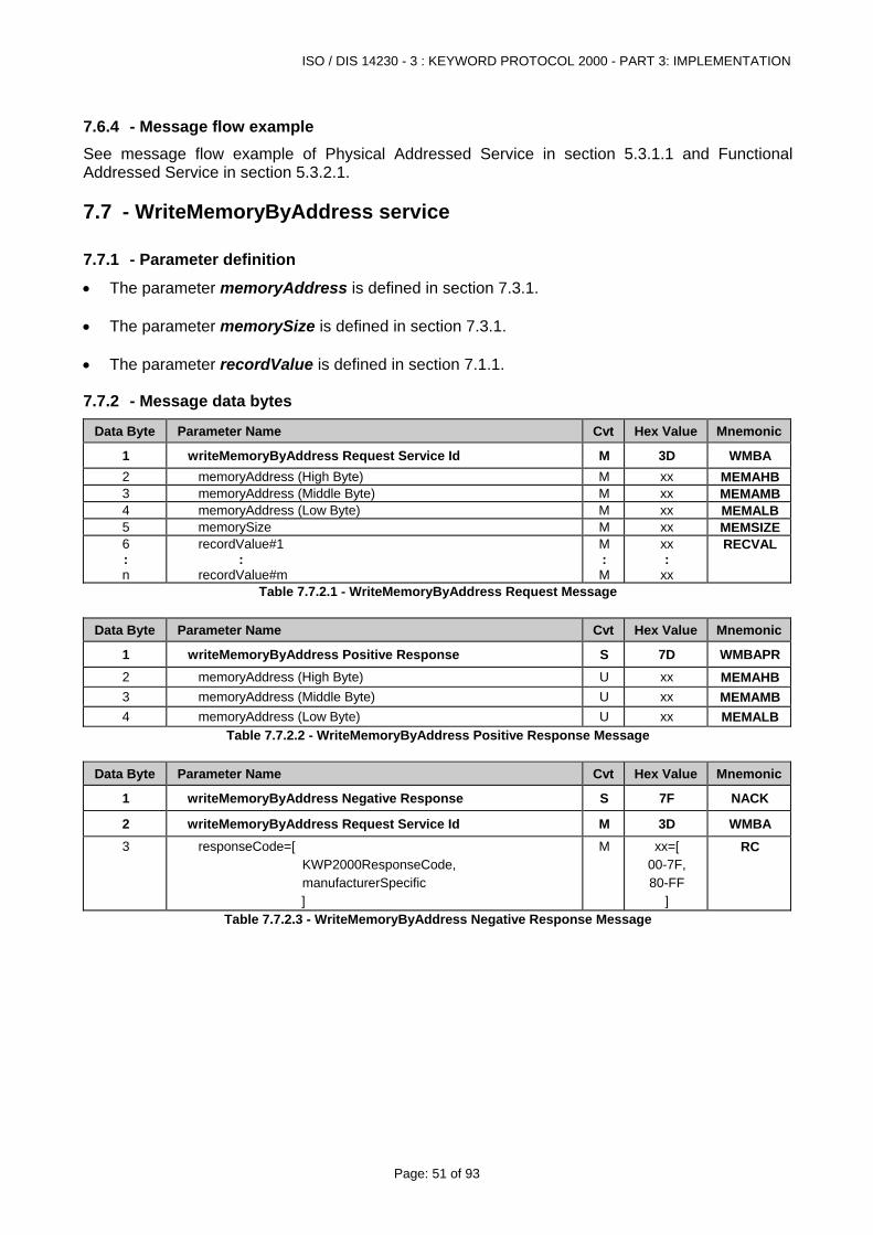
ISO / DIS 14230 - 3 : KEYWORD PROTOCOL 2000 - PART 3: IMPLEMENTATION
Page: 51 of 93
7.6.4 - Message flow example See message flow example of Physical Addressed Service in section 5.3.1.1 and Functional Addressed Service in section 5.3.2.1.
7.7 - WriteMemoryByAddress service
7.7.1 - Parameter definition
• The parameter memoryAddress is defined in section 7.3.1. • The parameter memorySize is defined in section 7.3.1. • The parameter recordValue is defined in section 7.1.1.
7.7.2 - Message data bytes
Data Byte Parameter Name Cvt Hex Value Mnemonic
1 writeMemoryByAddress Request Service Id M 3D WMBA 2 memoryAddress (High Byte) M xx MEMAHB3 memoryAddress (Middle Byte) M xx MEMAMB4 memoryAddress (Low Byte) M xx MEMALB5 memorySize M xx MEMSIZE6 : n
recordValue#1 : recordValue#m
M : M
xx :
xx
RECVAL
Table 7.7.2.1 - WriteMemoryByAddress Request Message
Data Byte Parameter Name Cvt Hex Value Mnemonic
1 writeMemoryByAddress Positive Response S 7D WMBAPR2 memoryAddress (High Byte) U xx MEMAHB3 memoryAddress (Middle Byte) U xx MEMAMB4 memoryAddress (Low Byte) U xx MEMALB
Table 7.7.2.2 - WriteMemoryByAddress Positive Response Message
Data Byte Parameter Name Cvt Hex Value Mnemonic
1 writeMemoryByAddress Negative Response S 7F NACK
2 writeMemoryByAddress Request Service Id M 3D WMBA 3 responseCode=[
KWP2000ResponseCode, manufacturerSpecific ]
M xx=[ 00-7F, 80-FF
]
RC
Table 7.7.2.3 - WriteMemoryByAddress Negative Response Message
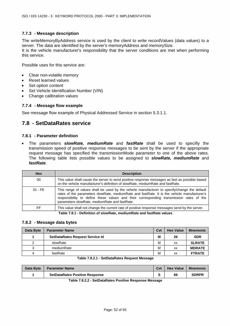
ISO / DIS 14230 - 3 : KEYWORD PROTOCOL 2000 - PART 3: IMPLEMENTATION
Page: 52 of 93
7.7.3 - Message description The writeMemoryByAddress service is used by the client to write recordValues (data values) to a server. The data are identified by the server's memoryAddress and memorySize. It is the vehicle manufacturer's responsibility that the server conditions are met when performing this service. Possible uses for this service are: • Clear non-volatile memory • Reset learned values • Set option content • Set Vehicle Identification Number (VIN) • Change calibration values
7.7.4 - Message flow example See message flow example of Physical Addressed Service in section 5.3.1.1.
7.8 - SetDataRates service
7.8.1 - Parameter definition
• The parameters slowRate, mediumRate and fastRate shall be used to specifiy the transmission speed of positive response messages to be sent by the server if the appropriate request message has specified the transmissionMode parameter to one of the above rates. The following table lists possible values to be assigned to slowRate, mediumRate and fastRate.
Hex Description
00 This value shall cause the server to send positive response messages as fast as possible based on the vehicle manufacturer's definition of slowRate, mediumRate and fastRate.
01 - FE This range of values shall be used by the vehicle manufacturer to specify/change the default rates of the parameters slowRate, mediumRate and fastRate. It is the vehicle manufacturer's responsibility to define these values and their corresponding transmission rates of the parameters slowRate, mediumRate and fastRate.
FF This value shall not change the current rate of positive response messages send by the server. Table 7.8.1 - Definition of slowRate, mediumRate and fastRate values
7.8.2 - Message data bytes
Data Byte Parameter Name Cvt Hex Value Mnemonic
1 SetDataRates Request Service Id M 26 SDR 2 slowRate M xx SLRATE 3 mediumRate M xx MDRATE4 fastRate M xx FTRATE
Table 7.8.2.1 - SetDataRates Request Message
Data Byte Parameter Name Cvt Hex Value Mnemonic
1 SetDataRates Positive Response S 66 SDRPR Table 7.8.2.2 - SetDataRates Positive Response Message
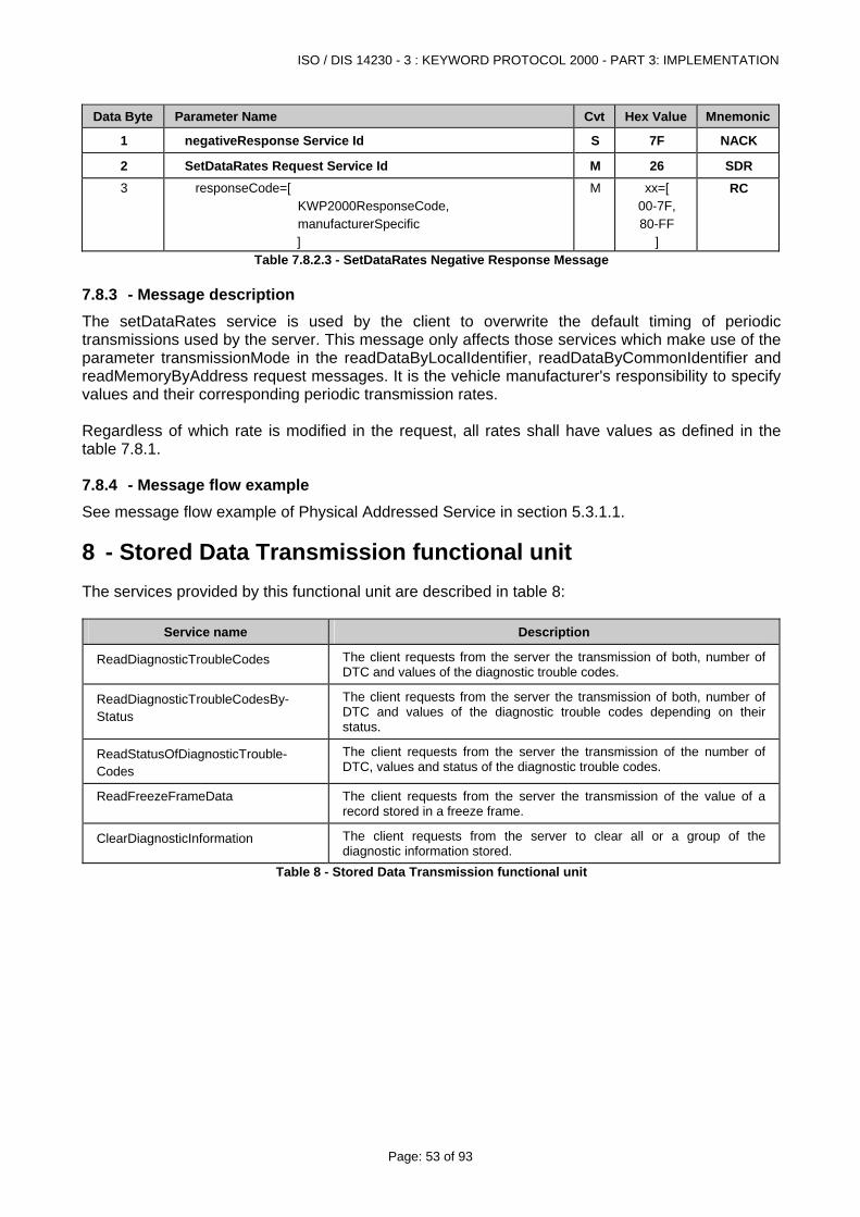
ISO / DIS 14230 - 3 : KEYWORD PROTOCOL 2000 - PART 3: IMPLEMENTATION
Page: 53 of 93
Data Byte Parameter Name Cvt Hex Value Mnemonic
1 negativeResponse Service Id S 7F NACK
2 SetDataRates Request Service Id M 26 SDR 3 responseCode=[
KWP2000ResponseCode, manufacturerSpecific ]
M xx=[ 00-7F, 80-FF
]
RC
Table 7.8.2.3 - SetDataRates Negative Response Message
7.8.3 - Message description The setDataRates service is used by the client to overwrite the default timing of periodic transmissions used by the server. This message only affects those services which make use of the parameter transmissionMode in the readDataByLocalIdentifier, readDataByCommonIdentifier and readMemoryByAddress request messages. It is the vehicle manufacturer's responsibility to specify values and their corresponding periodic transmission rates. Regardless of which rate is modified in the request, all rates shall have values as defined in the table 7.8.1.
7.8.4 - Message flow example See message flow example of Physical Addressed Service in section 5.3.1.1.
8 - Stored Data Transmission functional unit The services provided by this functional unit are described in table 8:
Service name Description
ReadDiagnosticTroubleCodes The client requests from the server the transmission of both, number of DTC and values of the diagnostic trouble codes.
ReadDiagnosticTroubleCodesBy-Status
The client requests from the server the transmission of both, number of DTC and values of the diagnostic trouble codes depending on their status.
ReadStatusOfDiagnosticTrouble-Codes
The client requests from the server the transmission of the number of DTC, values and status of the diagnostic trouble codes.
ReadFreezeFrameData The client requests from the server the transmission of the value of a record stored in a freeze frame.
ClearDiagnosticInformation The client requests from the server to clear all or a group of the diagnostic information stored.
Table 8 - Stored Data Transmission functional unit
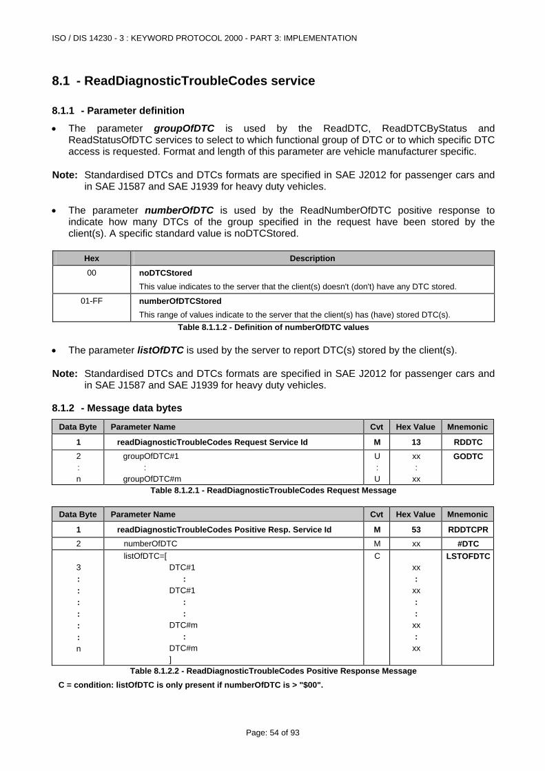
ISO / DIS 14230 - 3 : KEYWORD PROTOCOL 2000 - PART 3: IMPLEMENTATION
Page: 54 of 93
8.1 - ReadDiagnosticTroubleCodes service
8.1.1 - Parameter definition
• The parameter groupOfDTC is used by the ReadDTC, ReadDTCByStatus and ReadStatusOfDTC services to select to which functional group of DTC or to which specific DTC access is requested. Format and length of this parameter are vehicle manufacturer specific.
Note: Standardised DTCs and DTCs formats are specified in SAE J2012 for passenger cars and
in SAE J1587 and SAE J1939 for heavy duty vehicles. • The parameter numberOfDTC is used by the ReadNumberOfDTC positive response to
indicate how many DTCs of the group specified in the request have been stored by the client(s). A specific standard value is noDTCStored.
Hex Description
00 noDTCStored This value indicates to the server that the client(s) doesn't (don't) have any DTC stored.
01-FF numberOfDTCStored This range of values indicate to the server that the client(s) has (have) stored DTC(s).
Table 8.1.1.2 - Definition of numberOfDTC values • The parameter listOfDTC is used by the server to report DTC(s) stored by the client(s). Note: Standardised DTCs and DTCs formats are specified in SAE J2012 for passenger cars and
in SAE J1587 and SAE J1939 for heavy duty vehicles.
8.1.2 - Message data bytes
Data Byte Parameter Name Cvt Hex Value Mnemonic
1 readDiagnosticTroubleCodes Request Service Id M 13 RDDTC 2 : n
groupOfDTC#1 : groupOfDTC#m
U : U
xx :
xx
GODTC
Table 8.1.2.1 - ReadDiagnosticTroubleCodes Request Message
Data Byte Parameter Name Cvt Hex Value Mnemonic
1 readDiagnosticTroubleCodes Positive Resp. Service Id M 53 RDDTCPR2 numberOfDTC M xx #DTC 3 : : : : : : n
listOfDTC=[ DTC#1 : DTC#1 : : DTC#m : DTC#m ]
C
xx :
xx : :
xx :
xx
LSTOFDTC
Table 8.1.2.2 - ReadDiagnosticTroubleCodes Positive Response Message
C = condition: listOfDTC is only present if numberOfDTC is > "$00".
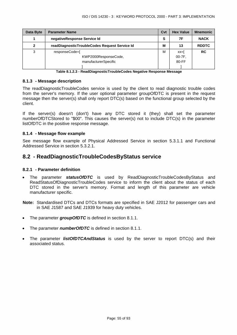
ISO / DIS 14230 - 3 : KEYWORD PROTOCOL 2000 - PART 3: IMPLEMENTATION
Page: 55 of 93
Data Byte Parameter Name Cvt Hex Value Mnemonic
1 negativeResponse Service Id S 7F NACK
2 readDiagnosticTroubleCodes Request Service Id M 13 RDDTC 3 responseCode=[
KWP2000ResponseCode, manufacturerSpecific ]
M xx=[ 00-7F, 80-FF
]
RC
Table 8.1.2.3 - ReadDiagnosticTroubleCodes Negative Response Message
8.1.3 - Message description The readDiagnosticTroubleCodes service is used by the client to read diagnostic trouble codes from the server's memory. If the user optional parameter groupOfDTC is present in the request message then the server(s) shall only report DTC(s) based on the functional group selected by the client. If the server(s) doesn't (don't) have any DTC stored it (they) shall set the parameter numberOfDTCStored to "$00". This causes the server(s) not to include DTC(s) in the parameter listOfDTC in the positive response message.
8.1.4 - Message flow example See message flow example of Physical Addressed Service in section 5.3.1.1 and Functional Addressed Service in section 5.3.2.1.
8.2 - ReadDiagnosticTroubleCodesByStatus service
8.2.1 - Parameter definition
• The parameter statusOfDTC is used by ReadDiagnosticTroubleCodesByStatus and ReadStatusOfDiagnosticTroubleCodes service to inform the client about the status of each DTC stored in the server's memory. Format and length of this parameter are vehicle manufacturer specific.
Note: Standardised DTCs and DTCs formats are specified in SAE J2012 for passenger cars and
in SAE J1587 and SAE J1939 for heavy duty vehicles. • The parameter groupOfDTC is defined in section 8.1.1. • The parameter numberOfDTC is defined in section 8.1.1. • The parameter listOfDTCAndStatus is used by the server to report DTC(s) and their
associated status.
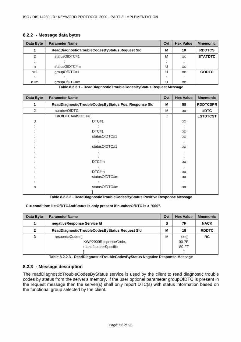
ISO / DIS 14230 - 3 : KEYWORD PROTOCOL 2000 - PART 3: IMPLEMENTATION
Page: 56 of 93
8.2.2 - Message data bytes
Data Byte Parameter Name Cvt Hex Value Mnemonic
1 ReadDiagnosticTroubleCodesByStatus Request SId M 18 RDDTCS2 : n
statusOfDTC#1 : statusOfDTC#m
M : U
xx :
xx
STATDTC
n+1 :
n+m
groupOfDTC#1 : groupOfDTC#m
U : U
xx :
xx
GODTC
Table 8.2.2.1 - ReadDiagnosticTroubleCodesByStatus Request Message
Data Byte Parameter Name Cvt Hex Value Mnemonic
1 ReadDiagnosticTroubleCodesByStatus Pos. Response SId M 58 RDDTCSPR2 numberOfDTC M xx #DTC 3 : : : : : : : : : : : : n
listOfDTCAndStatus=[ DTC#1 : DTC#1 statusOfDTC#1 : statusOfDTC#1 : : DTC#m : DTC#m statusOfDTC#m : statusOfDTC#m ]
C
xx :
xx xx :
xx : :
xx :
xx xx :
xx
LSTDTCST
Table 8.2.2.2 - ReadDiagnosticTroubleCodesByStatus Positive Response Message C = condition: listOfDTCAndStatus is only present if numberOfDTC is > "$00".
Data Byte Parameter Name Cvt Hex Value Mnemonic
1 negativeResponse Service Id S 7F NACK
2 ReadDiagnosticTroubleCodesByStatus Request SId M 18 RDDTC 3 responseCode=[
KWP2000ResponseCode, manufacturerSpecific ]
M xx=[ 00-7F, 80-FF
]
RC
Table 8.2.2.3 - ReadDiagnosticTroubleCodesByStatus Negative Response Message
8.2.3 - Message description The readDiagnosticTroubleCodesByStatus service is used by the client to read diagnostic trouble codes by status from the server's memory. If the user optional parameter groupOfDTC is present in the request message then the server(s) shall only report DTC(s) with status information based on the functional group selected by the client.
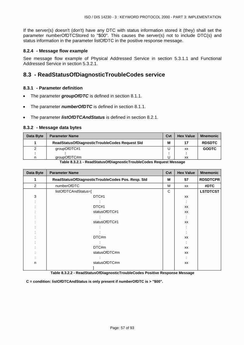
ISO / DIS 14230 - 3 : KEYWORD PROTOCOL 2000 - PART 3: IMPLEMENTATION
Page: 57 of 93
If the server(s) doesn't (don't) have any DTC with status information stored it (they) shall set the parameter numberOfDTCStored to "$00". This causes the server(s) not to include DTC(s) and status information in the parameter listOfDTC in the positive response message.
8.2.4 - Message flow example See message flow example of Physical Addressed Service in section 5.3.1.1 and Functional Addressed Service in section 5.3.2.1.
8.3 - ReadStatusOfDiagnosticTroubleCodes service
8.3.1 - Parameter definition
• The parameter groupOfDTC is defined in section 8.1.1. • The parameter numberOfDTC is defined in section 8.1.1. • The parameter listOfDTCAndStatus is defined in section 8.2.1.
8.3.2 - Message data bytes
Data Byte Parameter Name Cvt Hex Value Mnemonic
1 ReadStatusOfDiagnosticTroubleCodes Request SId M 17 RDSDTC2 : n
groupOfDTC#1 : groupOfDTC#m
U : U
xx :
xx
GODTC
Table 8.3.2.1 - ReadStatusOfDiagnosticTroubleCodes Request Message
Data Byte Parameter Name Cvt Hex Value Mnemonic
1 ReadStatusOfDiagnosticTroubleCodes Pos. Resp. SId M 57 RDSDTCPR2 numberOfDTC M xx #DTC 3 : : : : : : : : : : : : n
listOfDTCAndStatus=[ DTC#1 : DTC#1 statusOfDTC#1 : statusOfDTC#1 : : DTC#m : DTC#m statusOfDTC#m : statusOfDTC#m ]
C
xx :
xx xx :
xx : :
xx :
xx xx :
xx
LSTDTCST
Table 8.3.2.2 - ReadStatusOfDiagnosticTroubleCodes Positive Response Message C = condition: listOfDTCAndStatus is only present if numberOfDTC is > "$00".
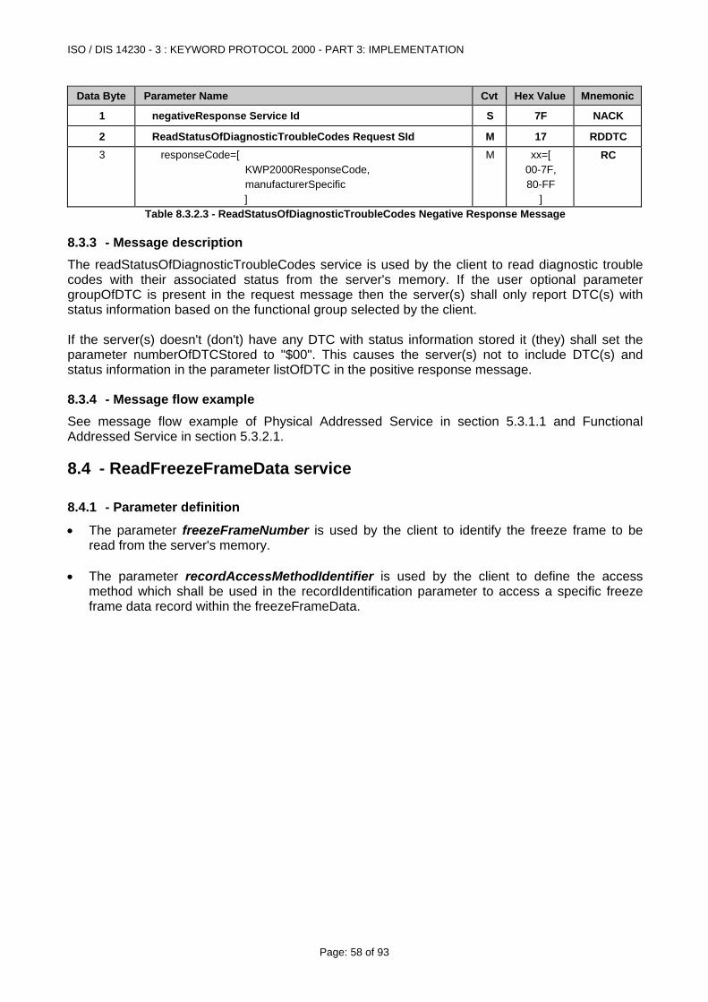
ISO / DIS 14230 - 3 : KEYWORD PROTOCOL 2000 - PART 3: IMPLEMENTATION
Page: 58 of 93
Data Byte Parameter Name Cvt Hex Value Mnemonic
1 negativeResponse Service Id S 7F NACK
2 ReadStatusOfDiagnosticTroubleCodes Request SId M 17 RDDTC 3 responseCode=[
KWP2000ResponseCode, manufacturerSpecific ]
M xx=[ 00-7F, 80-FF
]
RC
Table 8.3.2.3 - ReadStatusOfDiagnosticTroubleCodes Negative Response Message
8.3.3 - Message description The readStatusOfDiagnosticTroubleCodes service is used by the client to read diagnostic trouble codes with their associated status from the server's memory. If the user optional parameter groupOfDTC is present in the request message then the server(s) shall only report DTC(s) with status information based on the functional group selected by the client. If the server(s) doesn't (don't) have any DTC with status information stored it (they) shall set the parameter numberOfDTCStored to "$00". This causes the server(s) not to include DTC(s) and status information in the parameter listOfDTC in the positive response message.
8.3.4 - Message flow example See message flow example of Physical Addressed Service in section 5.3.1.1 and Functional Addressed Service in section 5.3.2.1.
8.4 - ReadFreezeFrameData service
8.4.1 - Parameter definition
• The parameter freezeFrameNumber is used by the client to identify the freeze frame to be read from the server's memory.
• The parameter recordAccessMethodIdentifier is used by the client to define the access
method which shall be used in the recordIdentification parameter to access a specific freeze frame data record within the freezeFrameData.
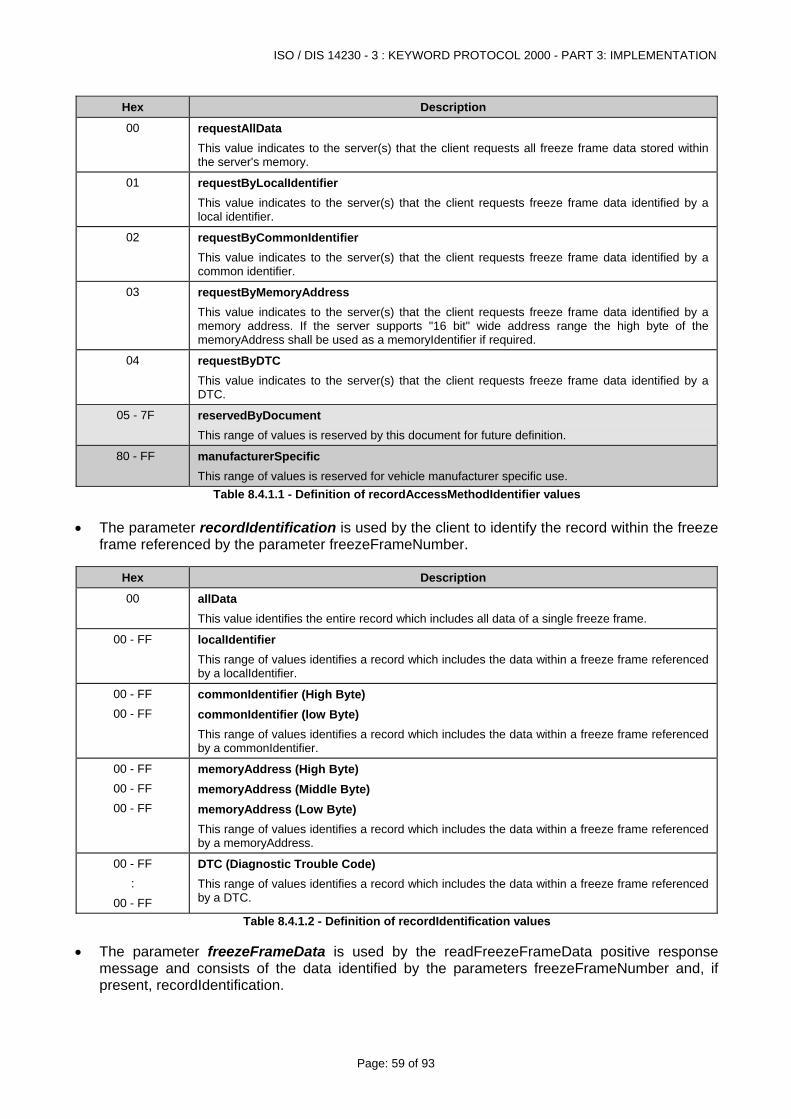
ISO / DIS 14230 - 3 : KEYWORD PROTOCOL 2000 - PART 3: IMPLEMENTATION
Page: 59 of 93
Hex Description
00 requestAllData This value indicates to the server(s) that the client requests all freeze frame data stored within the server's memory.
01 requestByLocalIdentifier This value indicates to the server(s) that the client requests freeze frame data identified by a local identifier.
02 requestByCommonIdentifier This value indicates to the server(s) that the client requests freeze frame data identified by a common identifier.
03 requestByMemoryAddress This value indicates to the server(s) that the client requests freeze frame data identified by a memory address. If the server supports "16 bit" wide address range the high byte of the memoryAddress shall be used as a memoryIdentifier if required.
04 requestByDTC This value indicates to the server(s) that the client requests freeze frame data identified by a DTC.
05 - 7F reservedByDocument This range of values is reserved by this document for future definition.
80 - FF manufacturerSpecific This range of values is reserved for vehicle manufacturer specific use.
Table 8.4.1.1 - Definition of recordAccessMethodIdentifier values • The parameter recordIdentification is used by the client to identify the record within the freeze
frame referenced by the parameter freezeFrameNumber.
Hex Description
00 allData This value identifies the entire record which includes all data of a single freeze frame.
00 - FF localIdentifier This range of values identifies a record which includes the data within a freeze frame referenced by a localIdentifier.
00 - FF 00 - FF
commonIdentifier (High Byte) commonIdentifier (low Byte) This range of values identifies a record which includes the data within a freeze frame referenced by a commonIdentifier.
00 - FF 00 - FF 00 - FF
memoryAddress (High Byte) memoryAddress (Middle Byte) memoryAddress (Low Byte) This range of values identifies a record which includes the data within a freeze frame referenced by a memoryAddress.
00 - FF :
00 - FF
DTC (Diagnostic Trouble Code) This range of values identifies a record which includes the data within a freeze frame referenced by a DTC.
Table 8.4.1.2 - Definition of recordIdentification values • The parameter freezeFrameData is used by the readFreezeFrameData positive response
message and consists of the data identified by the parameters freezeFrameNumber and, if present, recordIdentification.
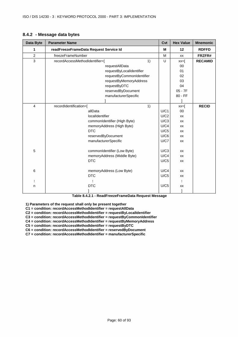
ISO / DIS 14230 - 3 : KEYWORD PROTOCOL 2000 - PART 3: IMPLEMENTATION
Page: 60 of 93
8.4.2 - Message data bytes
Data Byte Parameter Name Cvt Hex Value Mnemonic
1 readFreezeFrameData Request Service Id M 12 RDFFD 2 freezeFrameNumber M xx FRZFR# 3
recordAccessMethodIdentifier=[ 1) requestAllData requestByLocalIdentifier requestByCommonIdentifier requestByMemoryAddress requestByDTC reservedByDocument manufacturerSpecific ]
U
xx=[ 00 01 02 03 04
05 - 7F 80 - FF
]
RECAMID
4 5 6 : n
recordIdentification=[ 1) allData localIdentifier commonIdentifier (High Byte) memoryAddress (High Byte) DTC reservedByDocument manufacturerSpecific commonIdentifier (Low Byte) memoryAddress (Middle Byte) DTC memoryAddress (Low Byte) DTC : DTC ]
U/C1 U/C2 U/C3 U/C4 U/C5 U/C6 U/C7
U/C3 U/C4 U/C5
U/C4 U/C5
U/C5
xx=[ 00 xx xx xx xx xx xx
xx xx xx
xx xx :
xx ]
RECID
Table 8.4.2.1 - ReadFreezeFrameData Request Message 1) Parameters of the request shall only be present together C1 = condition: recordAccessMethodIdentifier = requestAllData C2 = condition: recordAccessMethodIdentifier = requestByLocalIdentifier C3 = condition: recordAccessMethodIdentifier = requestByCommonIdentifier C4 = condition: recordAccessMethodIdentifier = requestByMemoryAddress C5 = condition: recordAccessMethodIdentifier = requestByDTC C6 = condition: recordAccessMethodIdentifier = reservedByDocument C7 = condition: recordAccessMethodIdentifier = manufacturerSpecific
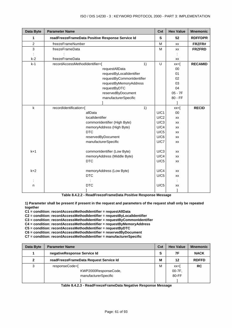
ISO / DIS 14230 - 3 : KEYWORD PROTOCOL 2000 - PART 3: IMPLEMENTATION
Page: 61 of 93
Data Byte Parameter Name Cvt Hex Value Mnemonic
1 readFreezeFrameData Positive Response Service Id S 52 RDFFDPR2 freezeFrameNumber M xx FRZFR# 3 :
k-2
freezeFrameData : freezeFrameData
M xx :
xx
FRZFRD
k-1
recordAccessMethodIdentifier=[ 1) requestAllData requestByLocalIdentifier requestByCommonIdentifier requestByMemoryAddress requestByDTC reservedByDocument manufacturerSpecific ]
U xx=[ 00 01 02 03 04
05 - 7F 80 - FF
]
RECAMID
k
k+1
k+2 : n
recordIdentification=[ 1) allData localIdentifier commonIdentifier (High Byte) memoryAddress (High Byte) DTC reservedByDocument manufacturerSpecific commonIdentifier (Low Byte) memoryAddress (Middle Byte) DTC memoryAddress (Low Byte) DTC : DTC ]
U/C1 U/C2 U/C3 U/C4 U/C5 U/C6 U/C7
U/C3 U/C4 U/C5
U/C4 U/C5
U/C5
xx=[ 00 xx xx xx xx xx xx
xx xx xx
xx xx :
xx ]
RECID
Table 8.4.2.2 - ReadFreezeFrameData Positive Response Message 1) Parameter shall be present if present in the request and parameters of the request shall only be repeated together C1 = condition: recordAccessMethodIdentifier = requestAllData C2 = condition: recordAccessMethodIdentifier = requestByLocalIdentifier C3 = condition: recordAccessMethodIdentifier = requestByCommonIdentifier C4 = condition: recordAccessMethodIdentifier = requestByMemoryAddress C5 = condition: recordAccessMethodIdentifier = requestByDTC C6 = condition: recordAccessMethodIdentifier = reservedByDocument C7 = condition: recordAccessMethodIdentifier = manufacturerSpecific
Data Byte Parameter Name Cvt Hex Value Mnemonic
1 negativeResponse Service Id S 7F NACK
2 readFreezeFrameData Request Service Id M 12 RDFFD 3 responseCode=[
KWP2000ResponseCode, manufacturerSpecific ]
M xx=[ 00-7F, 80-FF
]
RC
Table 8.4.2.3 - ReadFreezeFrameData Negative Response Message
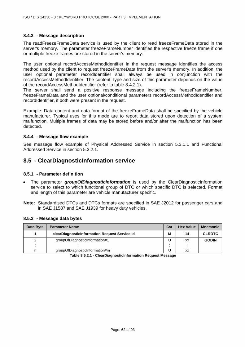
ISO / DIS 14230 - 3 : KEYWORD PROTOCOL 2000 - PART 3: IMPLEMENTATION
Page: 62 of 93
8.4.3 - Message description The readFreezeFrameData service is used by the client to read freezeFrameData stored in the server's memory. The parameter freezeFrameNumber identifies the respective freeze frame if one or multiple freeze frames are stored in the server's memory. The user optional recordAccessMethodIdentifier in the request message identifies the access method used by the client to request freezeFrameData from the server's memory. In addition, the user optional parameter recordIdentifier shall always be used in conjunction with the recordAccessMethodIdentifier. The content, type and size of this parameter depends on the value of the recordAccessMethodIdentifier (refer to table 8.4.2.1). The server shall send a positive response message including the freezeFrameNumber, freezeFrameData and the user optional/conditional parameters recordAccessMethodIdentifier and recordIdentifier, if both were present in the request. Example: Data content and data format of the freezeFrameData shall be specified by the vehicle manufacturer. Typical uses for this mode are to report data stored upon detection of a system malfunction. Multiple frames of data may be stored before and/or after the malfunction has been detected.
8.4.4 - Message flow example See message flow example of Physical Addressed Service in section 5.3.1.1 and Functional Addressed Service in section 5.3.2.1.
8.5 - ClearDiagnosticInformation service
8.5.1 - Parameter definition
• The parameter groupOfDiagnosticInformation is used by the ClearDiagnosticInformation service to select to which functional group of DTC or which specific DTC is selected. Format and length of this parameter are vehicle manufacturer specific.
Note: Standardised DTCs and DTCs formats are specified in SAE J2012 for passenger cars and
in SAE J1587 and SAE J1939 for heavy duty vehicles.
8.5.2 - Message data bytes
Data Byte Parameter Name Cvt Hex Value Mnemonic
1 clearDiagnosticInformation Request Service Id M 14 CLRDTC2 : n
groupOfDiagnosticInformation#1 : groupOfDiagnosticInformation#m
U : U
xx :
xx
GODIN
Table 8.5.2.1 - ClearDiagnosticInformation Request Message
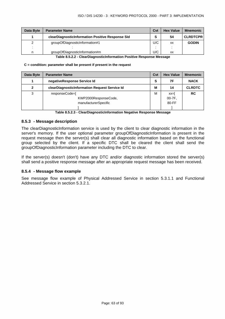
ISO / DIS 14230 - 3 : KEYWORD PROTOCOL 2000 - PART 3: IMPLEMENTATION
Page: 63 of 93
Data Byte Parameter Name Cvt Hex Value Mnemonic
1 clearDiagnosticInformation Positive Response SId S 54 CLRDTCPR2 : n
groupOfDiagnosticInformation#1 : groupOfDiagnosticInformation#m
U/C:
U/C
xx :
xx
GODIN
Table 8.5.2.2 - ClearDiagnosticInformation Positive Response Message C = condition: parameter shall be present if present in the request
Data Byte Parameter Name Cvt Hex Value Mnemonic
1 negativeResponse Service Id S 7F NACK
2 clearDiagnosticInformation Request Service Id M 14 CLRDTC3 responseCode=[
KWP2000ResponseCode, manufacturerSpecific ]
M xx=[ 00-7F, 80-FF
]
RC
Table 8.5.2.3 - ClearDiagnosticInformation Negative Response Message
8.5.3 - Message description The clearDiagnosticInformation service is used by the client to clear diagnostic information in the server's memory. If the user optional parameter groupOfDiagnosticInformation is present in the request message then the server(s) shall clear all diagnostic information based on the functional group selected by the client. If a specific DTC shall be cleared the client shall send the groupOfDiagnosticInformation parameter including the DTC to clear. If the server(s) doesn't (don't) have any DTC and/or diagnostic information stored the server(s) shall send a positive response message after an appropriate request message has been received.
8.5.4 - Message flow example See message flow example of Physical Addressed Service in section 5.3.1.1 and Functional Addressed Service in section 5.3.2.1.
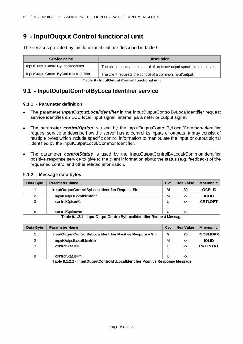
ISO / DIS 14230 - 3 : KEYWORD PROTOCOL 2000 - PART 3: IMPLEMENTATION
Page: 64 of 93
9 - InputOutput Control functional unit The services provided by this functional unit are described in table 9:
Service name Description
InputOutputControlByLocalIdentifier The client requests the control of an input/output specific to the server.
InputOutputControlByCommonIdentifier The client requests the control of a common input/output. Table 9 - InputOutput Control functional unit
9.1 - InputOutputControlByLocalIdentifier service
9.1.1 - Parameter definition
• The parameter inputOutputLocalIdentifier in the inputOutputControlByLocalIdentifier request service identifies an ECU local input signal, internal parameter or output signal.
• The parameter controlOption is used by the InputOutputControlByLocal/Common-Identifier
request service to describe how the server has to control its inputs or outputs. It may consist of multiple bytes which include specific control information to manipulate the input or output signal identified by the inputOutputLocal/CommonIdentifier.
• The parameter controlStatus is used by the InputOutputControlByLocal/CommonIdentifier
positive response service to give to the client information about the status (e.g. feedback) of the requested control and other related information.
9.1.2 - Message data bytes
Data Byte Parameter Name Cvt Hex Value Mnemonic
1 inputOutputControlByLocalIdentifier Request SId M 30 IOCBLID2 inputOutputLocalIdentifier M xx IOLID 3 : n
controlOption#1 : controlOption#m
U : U
xx :
xx
CRTLOPT
Table 9.1.2.1 - InputOutputControlByLocalldentifier Request Message
Data Byte Parameter Name Cvt Hex Value Mnemonic
1 inputOutputControlByLocalIdentifier Positive Response SId S 70 IOCBLIDPR2 inputOutputLocalIdentifier M xx IOLID 3 : n
controlStatus#1 : controlStatus#m
U : U
xx :
xx
CRTLSTAT
Table 9.1.2.2 - InputOutputControlByLocalldentifier Positive Response Message
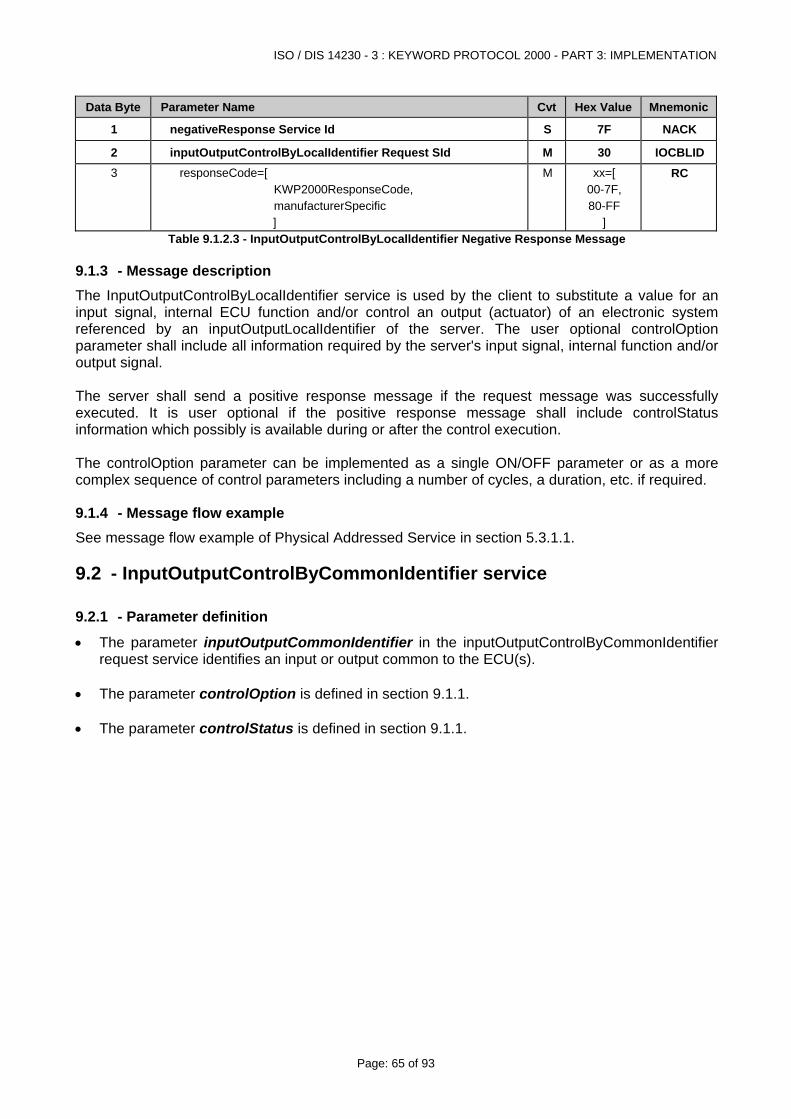
ISO / DIS 14230 - 3 : KEYWORD PROTOCOL 2000 - PART 3: IMPLEMENTATION
Page: 65 of 93
Data Byte Parameter Name Cvt Hex Value Mnemonic
1 negativeResponse Service Id S 7F NACK
2 inputOutputControlByLocalIdentifier Request SId M 30 IOCBLID3 responseCode=[
KWP2000ResponseCode, manufacturerSpecific ]
M xx=[ 00-7F, 80-FF
]
RC
Table 9.1.2.3 - InputOutputControlByLocalldentifier Negative Response Message
9.1.3 - Message description The InputOutputControlByLocalIdentifier service is used by the client to substitute a value for an input signal, internal ECU function and/or control an output (actuator) of an electronic system referenced by an inputOutputLocalIdentifier of the server. The user optional controlOption parameter shall include all information required by the server's input signal, internal function and/or output signal. The server shall send a positive response message if the request message was successfully executed. It is user optional if the positive response message shall include controlStatus information which possibly is available during or after the control execution. The controlOption parameter can be implemented as a single ON/OFF parameter or as a more complex sequence of control parameters including a number of cycles, a duration, etc. if required.
9.1.4 - Message flow example See message flow example of Physical Addressed Service in section 5.3.1.1.
9.2 - InputOutputControlByCommonIdentifier service
9.2.1 - Parameter definition
• The parameter inputOutputCommonIdentifier in the inputOutputControlByCommonIdentifier request service identifies an input or output common to the ECU(s).
• The parameter controlOption is defined in section 9.1.1. • The parameter controlStatus is defined in section 9.1.1.
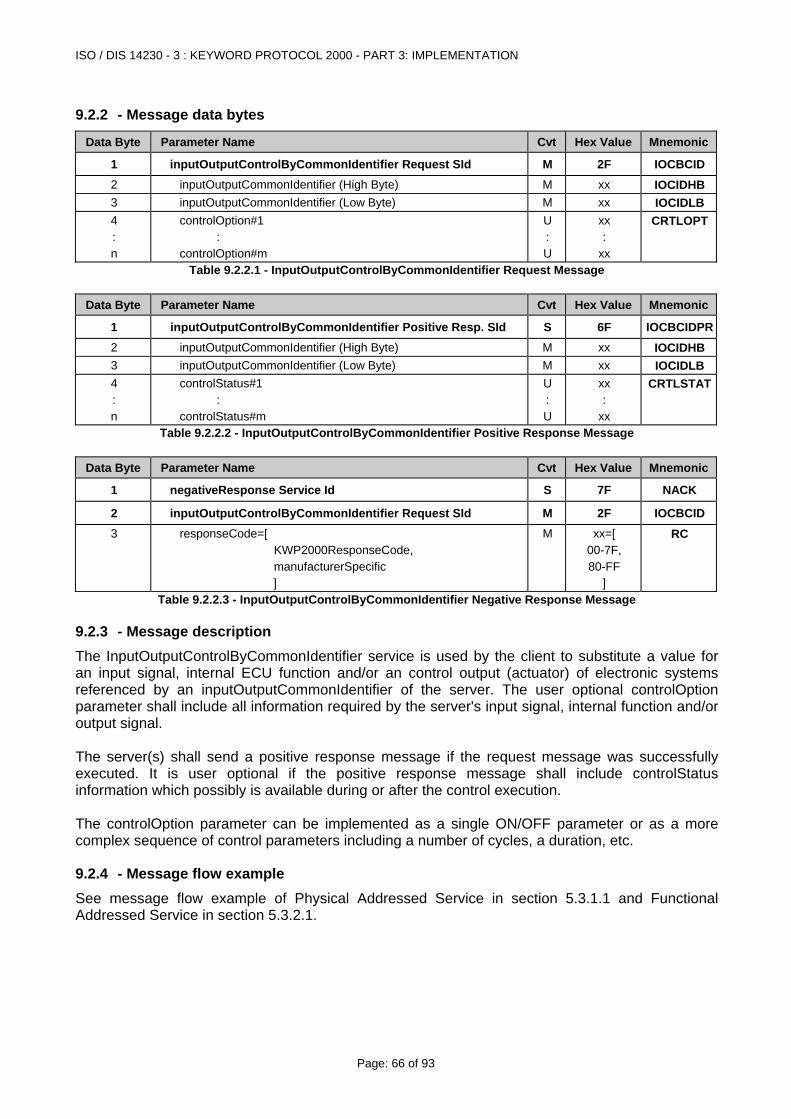
ISO / DIS 14230 - 3 : KEYWORD PROTOCOL 2000 - PART 3: IMPLEMENTATION
Page: 66 of 93
9.2.2 - Message data bytes
Data Byte Parameter Name Cvt Hex Value Mnemonic
1 inputOutputControlByCommonIdentifier Request SId M 2F IOCBCID2 inputOutputCommonIdentifier (High Byte) M xx IOCIDHB3 inputOutputCommonIdentifier (Low Byte) M xx IOCIDLB4 : n
controlOption#1 : controlOption#m
U : U
xx :
xx
CRTLOPT
Table 9.2.2.1 - InputOutputControlByCommonIdentifier Request Message
Data Byte Parameter Name Cvt Hex Value Mnemonic
1 inputOutputControlByCommonIdentifier Positive Resp. SId S 6F IOCBCIDPR2 inputOutputCommonIdentifier (High Byte) M xx IOCIDHB3 inputOutputCommonIdentifier (Low Byte) M xx IOCIDLB4 : n
controlStatus#1 : controlStatus#m
U : U
xx :
xx
CRTLSTAT
Table 9.2.2.2 - InputOutputControlByCommonIdentifier Positive Response Message
Data Byte Parameter Name Cvt Hex Value Mnemonic
1 negativeResponse Service Id S 7F NACK
2 inputOutputControlByCommonIdentifier Request SId M 2F IOCBCID3 responseCode=[
KWP2000ResponseCode, manufacturerSpecific ]
M xx=[ 00-7F, 80-FF
]
RC
Table 9.2.2.3 - InputOutputControlByCommonIdentifier Negative Response Message
9.2.3 - Message description The InputOutputControlByCommonIdentifier service is used by the client to substitute a value for an input signal, internal ECU function and/or an control output (actuator) of electronic systems referenced by an inputOutputCommonIdentifier of the server. The user optional controlOption parameter shall include all information required by the server's input signal, internal function and/or output signal. The server(s) shall send a positive response message if the request message was successfully executed. It is user optional if the positive response message shall include controlStatus information which possibly is available during or after the control execution. The controlOption parameter can be implemented as a single ON/OFF parameter or as a more complex sequence of control parameters including a number of cycles, a duration, etc.
9.2.4 - Message flow example See message flow example of Physical Addressed Service in section 5.3.1.1 and Functional Addressed Service in section 5.3.2.1.
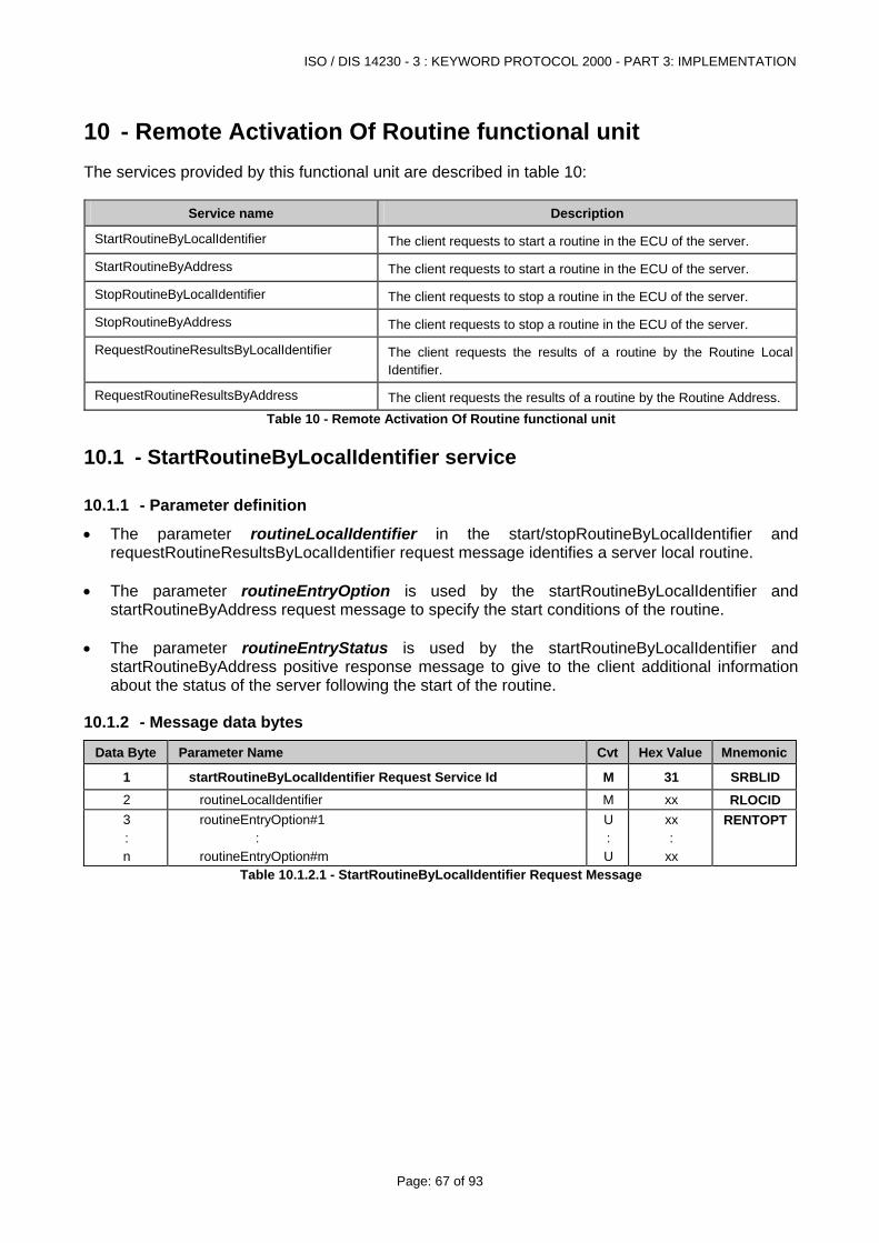
ISO / DIS 14230 - 3 : KEYWORD PROTOCOL 2000 - PART 3: IMPLEMENTATION
Page: 67 of 93
10 - Remote Activation Of Routine functional unit The services provided by this functional unit are described in table 10:
Service name Description
StartRoutineByLocalIdentifier The client requests to start a routine in the ECU of the server.
StartRoutineByAddress The client requests to start a routine in the ECU of the server.
StopRoutineByLocalIdentifier The client requests to stop a routine in the ECU of the server.
StopRoutineByAddress The client requests to stop a routine in the ECU of the server.
RequestRoutineResultsByLocalIdentifier The client requests the results of a routine by the Routine Local Identifier.
RequestRoutineResultsByAddress The client requests the results of a routine by the Routine Address. Table 10 - Remote Activation Of Routine functional unit
10.1 - StartRoutineByLocalIdentifier service
10.1.1 - Parameter definition
• The parameter routineLocalIdentifier in the start/stopRoutineByLocalIdentifier and requestRoutineResultsByLocalIdentifier request message identifies a server local routine.
• The parameter routineEntryOption is used by the startRoutineByLocalIdentifier and
startRoutineByAddress request message to specify the start conditions of the routine. • The parameter routineEntryStatus is used by the startRoutineByLocalIdentifier and
startRoutineByAddress positive response message to give to the client additional information about the status of the server following the start of the routine.
10.1.2 - Message data bytes
Data Byte Parameter Name Cvt Hex Value Mnemonic
1 startRoutineByLocalIdentifier Request Service Id M 31 SRBLID 2 routineLocalIdentifier M xx RLOCID 3 : n
routineEntryOption#1 : routineEntryOption#m
U : U
xx :
xx
RENTOPT
Table 10.1.2.1 - StartRoutineByLocalIdentifier Request Message
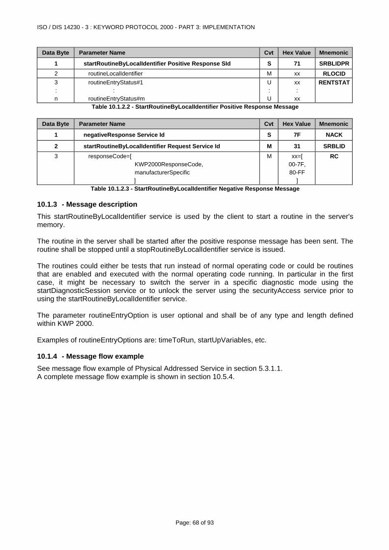
ISO / DIS 14230 - 3 : KEYWORD PROTOCOL 2000 - PART 3: IMPLEMENTATION
Page: 68 of 93
Data Byte Parameter Name Cvt Hex Value Mnemonic
1 startRoutineByLocalIdentifier Positive Response SId S 71 SRBLIDPR2 routineLocalIdentifier M xx RLOCID 3 : n
routineEntryStatus#1 : routineEntryStatus#m
U : U
xx :
xx
RENTSTAT
Table 10.1.2.2 - StartRoutineByLocalIdentifier Positive Response Message
Data Byte Parameter Name Cvt Hex Value Mnemonic
1 negativeResponse Service Id S 7F NACK
2 startRoutineByLocalIdentifier Request Service Id M 31 SRBLID 3 responseCode=[
KWP2000ResponseCode, manufacturerSpecific ]
M xx=[ 00-7F, 80-FF
]
RC
Table 10.1.2.3 - StartRoutineByLocalIdentifier Negative Response Message
10.1.3 - Message description This startRoutineByLocalIdentifier service is used by the client to start a routine in the server's memory. The routine in the server shall be started after the positive response message has been sent. The routine shall be stopped until a stopRoutineByLocalIdentifier service is issued. The routines could either be tests that run instead of normal operating code or could be routines that are enabled and executed with the normal operating code running. In particular in the first case, it might be necessary to switch the server in a specific diagnostic mode using the startDiagnosticSession service or to unlock the server using the securityAccess service prior to using the startRoutineByLocalIdentifier service. The parameter routineEntryOption is user optional and shall be of any type and length defined within KWP 2000. Examples of routineEntryOptions are: timeToRun, startUpVariables, etc.
10.1.4 - Message flow example See message flow example of Physical Addressed Service in section 5.3.1.1. A complete message flow example is shown in section 10.5.4.
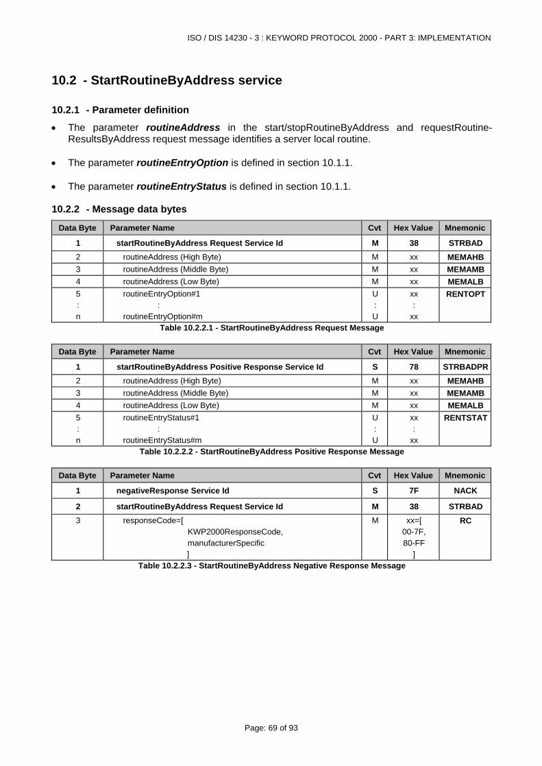
ISO / DIS 14230 - 3 : KEYWORD PROTOCOL 2000 - PART 3: IMPLEMENTATION
Page: 69 of 93
10.2 - StartRoutineByAddress service
10.2.1 - Parameter definition
• The parameter routineAddress in the start/stopRoutineByAddress and requestRoutine-ResultsByAddress request message identifies a server local routine.
• The parameter routineEntryOption is defined in section 10.1.1. • The parameter routineEntryStatus is defined in section 10.1.1.
10.2.2 - Message data bytes
Data Byte Parameter Name Cvt Hex Value Mnemonic
1 startRoutineByAddress Request Service Id M 38 STRBAD2 routineAddress (High Byte) M xx MEMAHB3 routineAddress (Middle Byte) M xx MEMAMB4 routineAddress (Low Byte) M xx MEMALB5 : n
routineEntryOption#1 : routineEntryOption#m
U : U
xx :
xx
RENTOPT
Table 10.2.2.1 - StartRoutineByAddress Request Message
Data Byte Parameter Name Cvt Hex Value Mnemonic
1 startRoutineByAddress Positive Response Service Id S 78 STRBADPR2 routineAddress (High Byte) M xx MEMAHB3 routineAddress (Middle Byte) M xx MEMAMB4 routineAddress (Low Byte) M xx MEMALB5 : n
routineEntryStatus#1 : routineEntryStatus#m
U : U
xx :
xx
RENTSTAT
Table 10.2.2.2 - StartRoutineByAddress Positive Response Message
Data Byte Parameter Name Cvt Hex Value Mnemonic
1 negativeResponse Service Id S 7F NACK
2 startRoutineByAddress Request Service Id M 38 STRBAD3 responseCode=[
KWP2000ResponseCode, manufacturerSpecific ]
M xx=[ 00-7F, 80-FF
]
RC
Table 10.2.2.3 - StartRoutineByAddress Negative Response Message
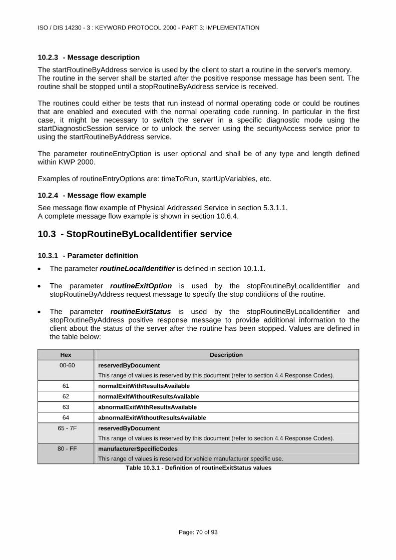
ISO / DIS 14230 - 3 : KEYWORD PROTOCOL 2000 - PART 3: IMPLEMENTATION
Page: 70 of 93
10.2.3 - Message description The startRoutineByAddress service is used by the client to start a routine in the server's memory. The routine in the server shall be started after the positive response message has been sent. The routine shall be stopped until a stopRoutineByAddress service is received. The routines could either be tests that run instead of normal operating code or could be routines that are enabled and executed with the normal operating code running. In particular in the first case, it might be necessary to switch the server in a specific diagnostic mode using the startDiagnosticSession service or to unlock the server using the securityAccess service prior to using the startRoutineByAddress service. The parameter routineEntryOption is user optional and shall be of any type and length defined within KWP 2000. Examples of routineEntryOptions are: timeToRun, startUpVariables, etc.
10.2.4 - Message flow example See message flow example of Physical Addressed Service in section 5.3.1.1. A complete message flow example is shown in section 10.6.4.
10.3 - StopRoutineByLocalIdentifier service
10.3.1 - Parameter definition
• The parameter routineLocalIdentifier is defined in section 10.1.1. • The parameter routineExitOption is used by the stopRoutineByLocalIdentifier and
stopRoutineByAddress request message to specify the stop conditions of the routine. • The parameter routineExitStatus is used by the stopRoutineByLocalIdentifier and
stopRoutineByAddress positive response message to provide additional information to the client about the status of the server after the routine has been stopped. Values are defined in the table below:
Hex Description
00-60 reservedByDocument This range of values is reserved by this document (refer to section 4.4 Response Codes).
61 normalExitWithResultsAvailable
62 normalExitWithoutResultsAvailable
63 abnormalExitWithResultsAvailable
64 abnormalExitWithoutResultsAvailable
65 - 7F reservedByDocument This range of values is reserved by this document (refer to section 4.4 Response Codes).
80 - FF manufacturerSpecificCodes This range of values is reserved for vehicle manufacturer specific use.
Table 10.3.1 - Definition of routineExitStatus values
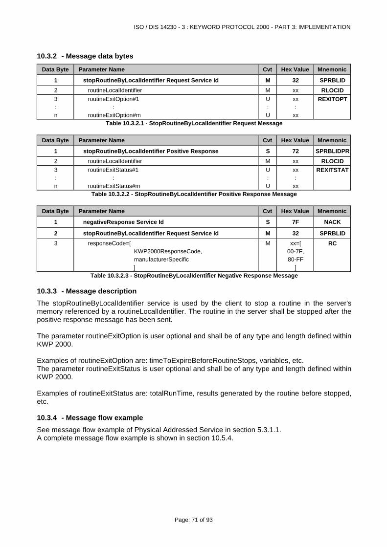
ISO / DIS 14230 - 3 : KEYWORD PROTOCOL 2000 - PART 3: IMPLEMENTATION
Page: 71 of 93
10.3.2 - Message data bytes
Data Byte Parameter Name Cvt Hex Value Mnemonic
1 stopRoutineByLocalIdentifier Request Service Id M 32 SPRBLID2 routineLocalIdentifier M xx RLOCID 3 : n
routineExitOption#1 : routineExitOption#m
U : U
xx :
xx
REXITOPT
Table 10.3.2.1 - StopRoutineByLocalIdentifier Request Message
Data Byte Parameter Name Cvt Hex Value Mnemonic
1 stopRoutineByLocalIdentifier Positive Response S 72 SPRBLIDPR2 routineLocalIdentifier M xx RLOCID 3 : n
routineExitStatus#1 : routineExitStatus#m
U : U
xx :
xx
REXITSTAT
Table 10.3.2.2 - StopRoutineByLocalIdentifier Positive Response Message
Data Byte Parameter Name Cvt Hex Value Mnemonic
1 negativeResponse Service Id S 7F NACK
2 stopRoutineByLocalIdentifier Request Service Id M 32 SPRBLID3 responseCode=[
KWP2000ResponseCode, manufacturerSpecific ]
M xx=[ 00-7F, 80-FF
]
RC
Table 10.3.2.3 - StopRoutineByLocalIdentifier Negative Response Message
10.3.3 - Message description The stopRoutineByLocalIdentifier service is used by the client to stop a routine in the server's memory referenced by a routineLocalIdentifier. The routine in the server shall be stopped after the positive response message has been sent. The parameter routineExitOption is user optional and shall be of any type and length defined within KWP 2000. Examples of routineExitOption are: timeToExpireBeforeRoutineStops, variables, etc. The parameter routineExitStatus is user optional and shall be of any type and length defined within KWP 2000. Examples of routineExitStatus are: totalRunTime, results generated by the routine before stopped, etc.
10.3.4 - Message flow example See message flow example of Physical Addressed Service in section 5.3.1.1. A complete message flow example is shown in section 10.5.4.
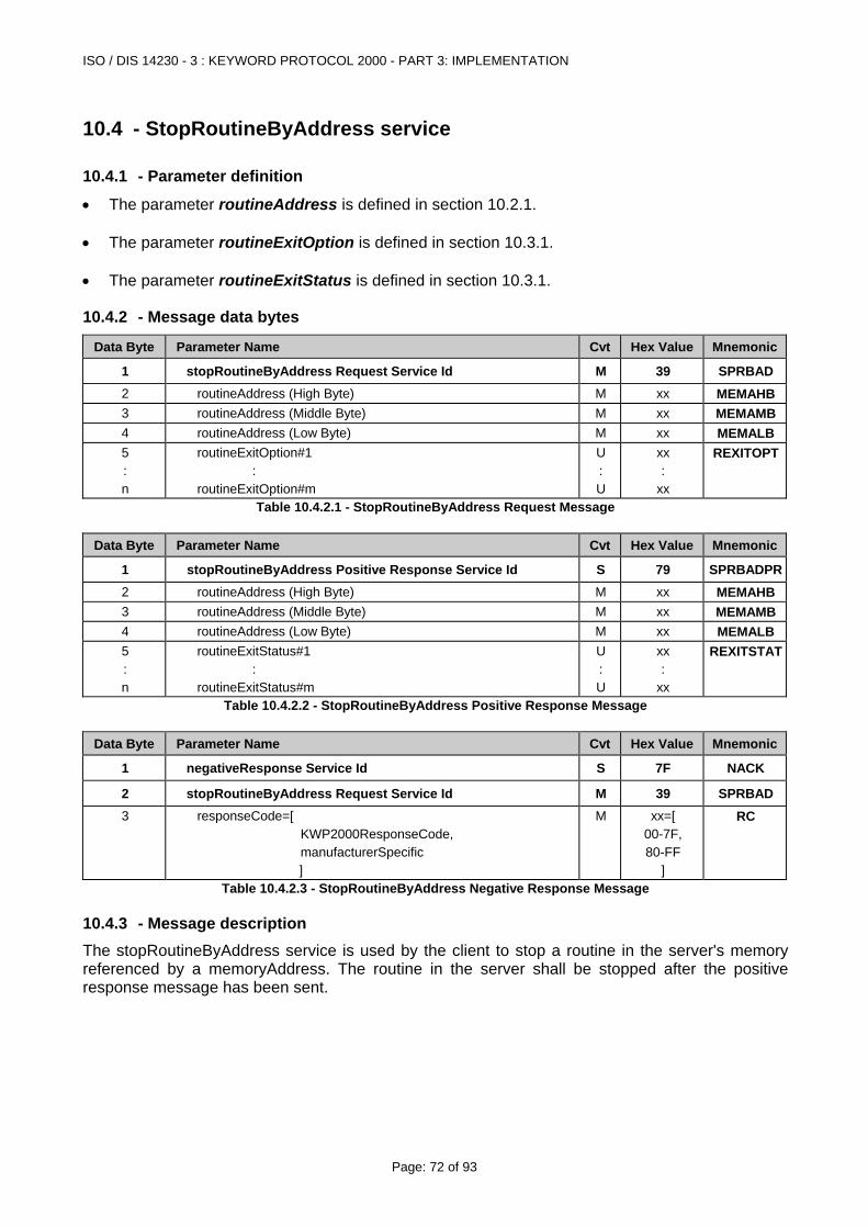
ISO / DIS 14230 - 3 : KEYWORD PROTOCOL 2000 - PART 3: IMPLEMENTATION
Page: 72 of 93
10.4 - StopRoutineByAddress service
10.4.1 - Parameter definition
• The parameter routineAddress is defined in section 10.2.1. • The parameter routineExitOption is defined in section 10.3.1. • The parameter routineExitStatus is defined in section 10.3.1.
10.4.2 - Message data bytes
Data Byte Parameter Name Cvt Hex Value Mnemonic
1 stopRoutineByAddress Request Service Id M 39 SPRBAD2 routineAddress (High Byte) M xx MEMAHB3 routineAddress (Middle Byte) M xx MEMAMB4 routineAddress (Low Byte) M xx MEMALB5 : n
routineExitOption#1 : routineExitOption#m
U : U
xx :
xx
REXITOPT
Table 10.4.2.1 - StopRoutineByAddress Request Message
Data Byte Parameter Name Cvt Hex Value Mnemonic
1 stopRoutineByAddress Positive Response Service Id S 79 SPRBADPR2 routineAddress (High Byte) M xx MEMAHB3 routineAddress (Middle Byte) M xx MEMAMB4 routineAddress (Low Byte) M xx MEMALB5 : n
routineExitStatus#1 : routineExitStatus#m
U : U
xx :
xx
REXITSTAT
Table 10.4.2.2 - StopRoutineByAddress Positive Response Message
Data Byte Parameter Name Cvt Hex Value Mnemonic
1 negativeResponse Service Id S 7F NACK
2 stopRoutineByAddress Request Service Id M 39 SPRBAD3 responseCode=[
KWP2000ResponseCode, manufacturerSpecific ]
M xx=[ 00-7F, 80-FF
]
RC
Table 10.4.2.3 - StopRoutineByAddress Negative Response Message
10.4.3 - Message description The stopRoutineByAddress service is used by the client to stop a routine in the server's memory referenced by a memoryAddress. The routine in the server shall be stopped after the positive response message has been sent.
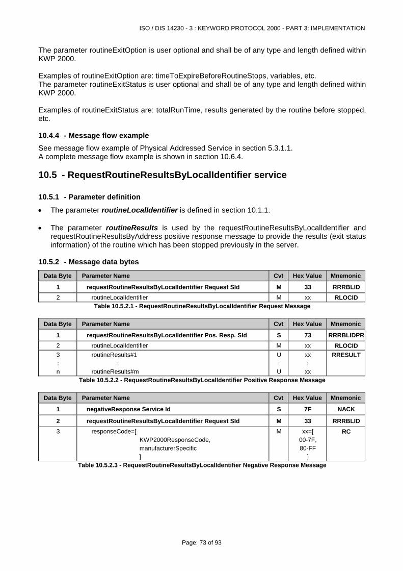
ISO / DIS 14230 - 3 : KEYWORD PROTOCOL 2000 - PART 3: IMPLEMENTATION
Page: 73 of 93
The parameter routineExitOption is user optional and shall be of any type and length defined within KWP 2000. Examples of routineExitOption are: timeToExpireBeforeRoutineStops, variables, etc. The parameter routineExitStatus is user optional and shall be of any type and length defined within KWP 2000. Examples of routineExitStatus are: totalRunTime, results generated by the routine before stopped, etc.
10.4.4 - Message flow example See message flow example of Physical Addressed Service in section 5.3.1.1. A complete message flow example is shown in section 10.6.4.
10.5 - RequestRoutineResultsByLocalIdentifier service
10.5.1 - Parameter definition
• The parameter routineLocalIdentifier is defined in section 10.1.1. • The parameter routineResults is used by the requestRoutineResultsByLocalIdentifier and
requestRoutineResultsByAddress positive response message to provide the results (exit status information) of the routine which has been stopped previously in the server.
10.5.2 - Message data bytes
Data Byte Parameter Name Cvt Hex Value Mnemonic
1 requestRoutineResultsByLocalIdentifier Request SId M 33 RRRBLID2 routineLocalIdentifier M xx RLOCID
Table 10.5.2.1 - RequestRoutineResultsByLocalIdentifier Request Message
Data Byte Parameter Name Cvt Hex Value Mnemonic
1 requestRoutineResultsByLocalIdentifier Pos. Resp. SId S 73 RRRBLIDPR2 routineLocalIdentifier M xx RLOCID 3 : n
routineResults#1 : routineResults#m
U : U
xx :
xx
RRESULT
Table 10.5.2.2 - RequestRoutineResultsByLocalIdentifier Positive Response Message
Data Byte Parameter Name Cvt Hex Value Mnemonic
1 negativeResponse Service Id S 7F NACK
2 requestRoutineResultsByLocalIdentifier Request SId M 33 RRRBLID3 responseCode=[
KWP2000ResponseCode, manufacturerSpecific ]
M xx=[ 00-7F, 80-FF
]
RC
Table 10.5.2.3 - RequestRoutineResultsByLocalIdentifier Negative Response Message
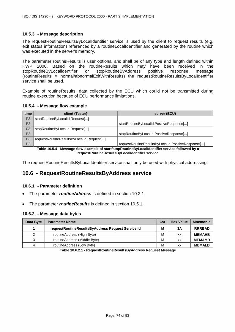
ISO / DIS 14230 - 3 : KEYWORD PROTOCOL 2000 - PART 3: IMPLEMENTATION
Page: 74 of 93
10.5.3 - Message description The requestRoutineResultsByLocalIdentifier service is used by the client to request results (e.g. exit status information) referenced by a routineLocalIdentifier and generated by the routine which was executed in the server's memory. The parameter routineResults is user optional and shall be of any type and length defined within KWP 2000. Based on the routineResults which may have been received in the stopRoutineByLocalidentifier or stopRoutineByAddress positive response message (routineResults = normal/abnormalExitWithResults) the requestRoutineResultsByLocalIdentifier service shall be used. Example of routineResults: data collected by the ECU which could not be transmitted during routine execution because of ECU performance limitations.
10.5.4 - Message flow example time client (Tester) server (ECU) P3 P2
startRoutineByLocalId.Request[...]
startRoutineByLocalId.PositiveResponse[...]
P3 P2
stopRoutineByLocalId.Request[...]
stopRoutineByLocalId.PositiveResponse[...]
P3 P2
requestRoutineResultsByLocalId.Request[...]
requestRoutineResultsByLocalId.PositiveResponse[...]
Table 10.5.4 - Message flow example of start/stopRoutineByLocalIdentifier service followed by a requestRoutineResultsByLocalIdentifier service
The requestRoutineResultsByLocalIdentifier service shall only be used with physical addressing.
10.6 - RequestRoutineResultsByAddress service
10.6.1 - Parameter definition
• The parameter routineAddress is defined in section 10.2.1. • The parameter routineResults is defined in section 10.5.1.
10.6.2 - Message data bytes
Data Byte Parameter Name Cvt Hex Value Mnemonic
1 requestRoutineResultsByAddress Request Service Id M 3A RRRBAD2 routineAddress (High Byte) M xx MEMAHB3 routineAddress (Middle Byte) M xx MEMAMB4 routineAddress (Low Byte) M xx MEMALB
Table 10.6.2.1 - RequestRoutineResultsByAddress Request Message
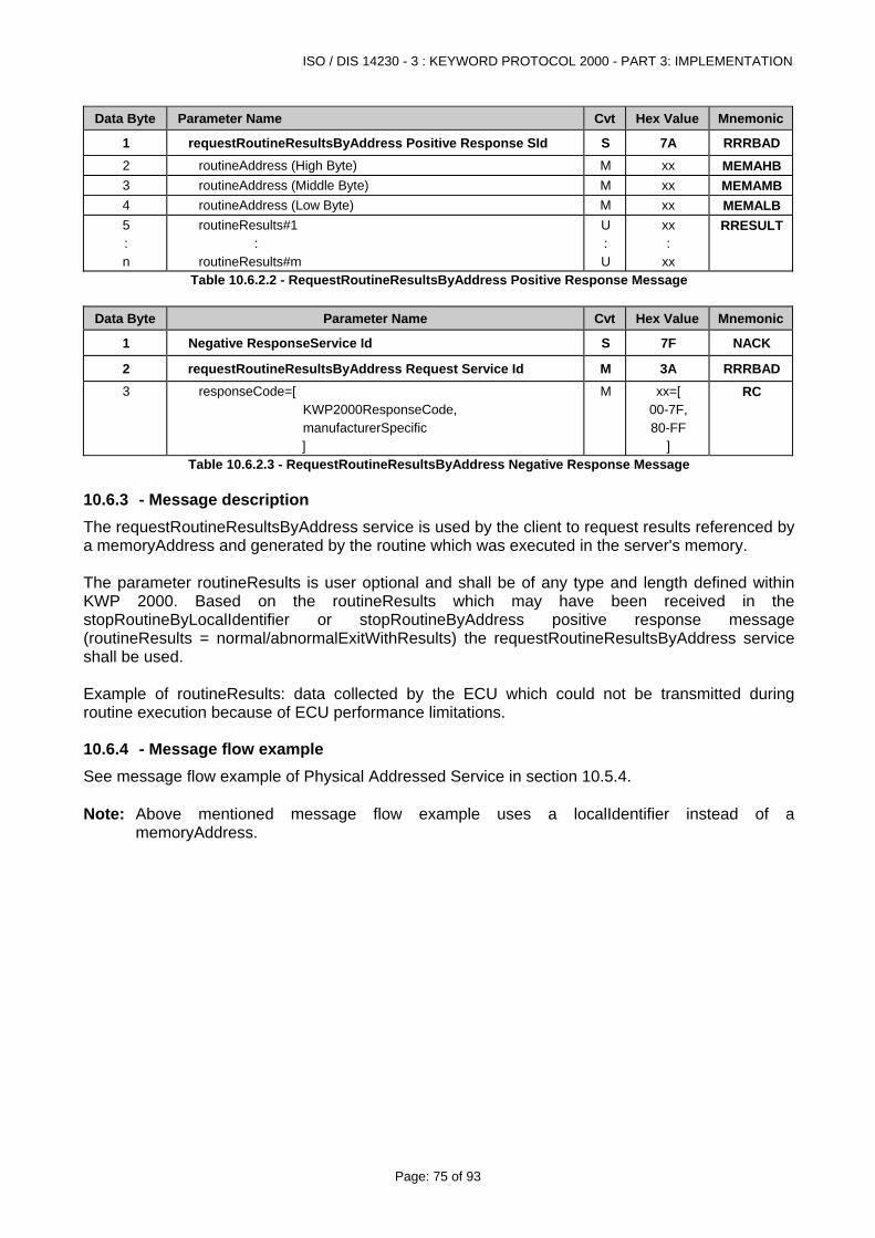
ISO / DIS 14230 - 3 : KEYWORD PROTOCOL 2000 - PART 3: IMPLEMENTATION
Page: 75 of 93
Data Byte Parameter Name Cvt Hex Value Mnemonic
1 requestRoutineResultsByAddress Positive Response SId S 7A RRRBAD2 routineAddress (High Byte) M xx MEMAHB3 routineAddress (Middle Byte) M xx MEMAMB4 routineAddress (Low Byte) M xx MEMALB5 : n
routineResults#1 : routineResults#m
U : U
xx :
xx
RRESULT
Table 10.6.2.2 - RequestRoutineResultsByAddress Positive Response Message
Data Byte Parameter Name Cvt Hex Value Mnemonic
1 Negative ResponseService Id S 7F NACK
2 requestRoutineResultsByAddress Request Service Id M 3A RRRBAD3 responseCode=[
KWP2000ResponseCode, manufacturerSpecific ]
M xx=[ 00-7F, 80-FF
]
RC
Table 10.6.2.3 - RequestRoutineResultsByAddress Negative Response Message
10.6.3 - Message description The requestRoutineResultsByAddress service is used by the client to request results referenced by a memoryAddress and generated by the routine which was executed in the server's memory. The parameter routineResults is user optional and shall be of any type and length defined within KWP 2000. Based on the routineResults which may have been received in the stopRoutineByLocalIdentifier or stopRoutineByAddress positive response message (routineResults = normal/abnormalExitWithResults) the requestRoutineResultsByAddress service shall be used. Example of routineResults: data collected by the ECU which could not be transmitted during routine execution because of ECU performance limitations.
10.6.4 - Message flow example See message flow example of Physical Addressed Service in section 10.5.4. Note: Above mentioned message flow example uses a localIdentifier instead of a
memoryAddress.
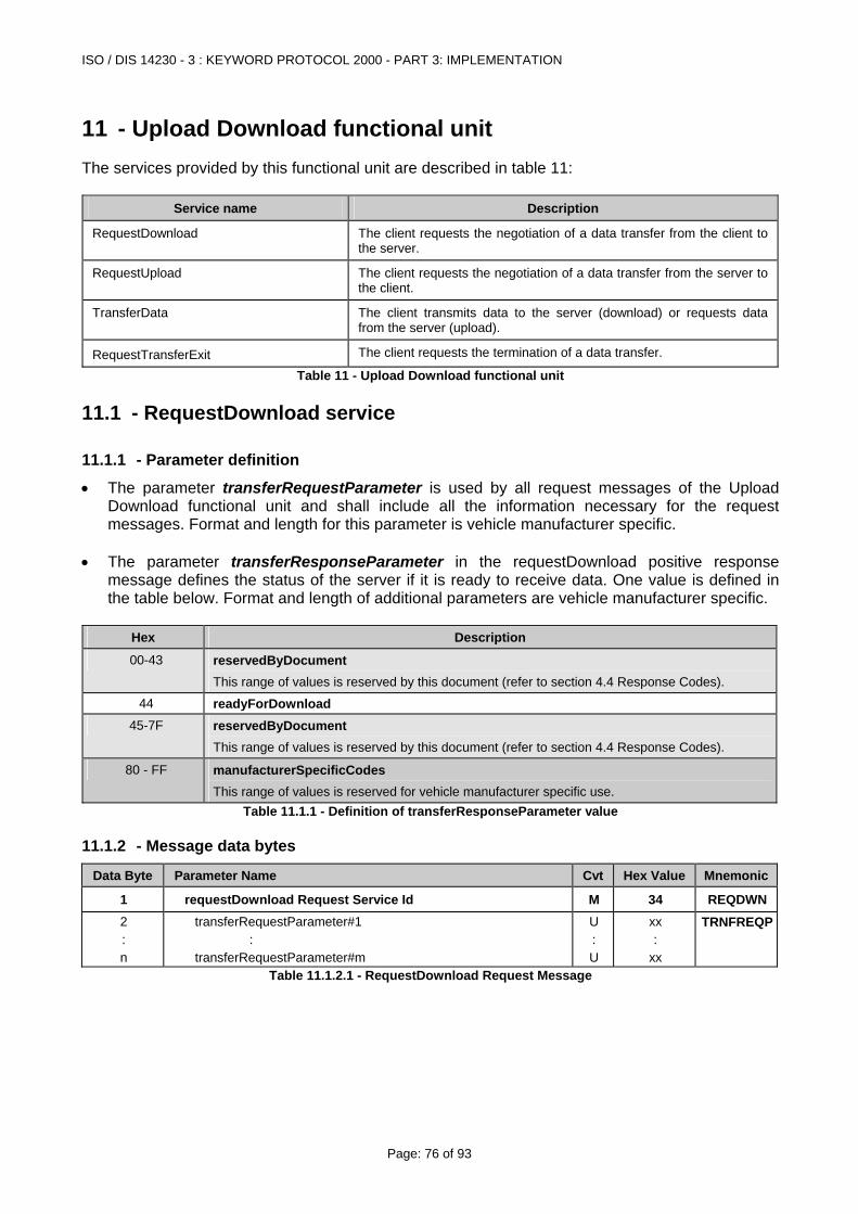
ISO / DIS 14230 - 3 : KEYWORD PROTOCOL 2000 - PART 3: IMPLEMENTATION
Page: 76 of 93
11 - Upload Download functional unit The services provided by this functional unit are described in table 11:
Service name Description
RequestDownload The client requests the negotiation of a data transfer from the client to the server.
RequestUpload The client requests the negotiation of a data transfer from the server to the client.
TransferData The client transmits data to the server (download) or requests data from the server (upload).
RequestTransferExit The client requests the termination of a data transfer.
Table 11 - Upload Download functional unit
11.1 - RequestDownload service
11.1.1 - Parameter definition
• The parameter transferRequestParameter is used by all request messages of the Upload Download functional unit and shall include all the information necessary for the request messages. Format and length for this parameter is vehicle manufacturer specific.
• The parameter transferResponseParameter in the requestDownload positive response
message defines the status of the server if it is ready to receive data. One value is defined in the table below. Format and length of additional parameters are vehicle manufacturer specific.
Hex Description
00-43 reservedByDocument This range of values is reserved by this document (refer to section 4.4 Response Codes).
44 readyForDownload
45-7F reservedByDocument This range of values is reserved by this document (refer to section 4.4 Response Codes).
80 - FF manufacturerSpecificCodes This range of values is reserved for vehicle manufacturer specific use.
Table 11.1.1 - Definition of transferResponseParameter value
11.1.2 - Message data bytes
Data Byte Parameter Name Cvt Hex Value Mnemonic
1 requestDownload Request Service Id M 34 REQDWN2 : n
transferRequestParameter#1 : transferRequestParameter#m
U : U
xx :
xx
TRNFREQP
Table 11.1.2.1 - RequestDownload Request Message
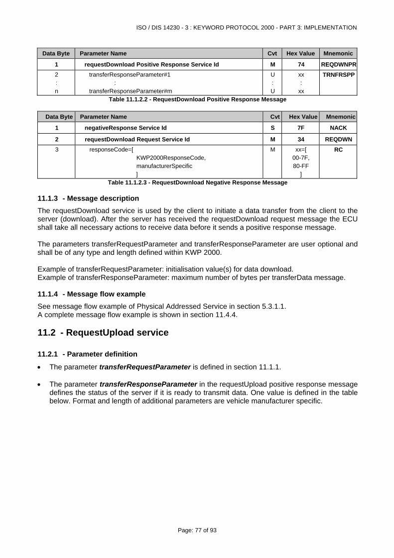
ISO / DIS 14230 - 3 : KEYWORD PROTOCOL 2000 - PART 3: IMPLEMENTATION
Page: 77 of 93
Data Byte Parameter Name Cvt Hex Value Mnemonic
1 requestDownload Positive Response Service Id M 74 REQDWNPR2 : n
transferResponseParameter#1 : transferResponseParameter#m
U : U
xx :
xx
TRNFRSPP
Table 11.1.2.2 - RequestDownload Positive Response Message
Data Byte Parameter Name Cvt Hex Value Mnemonic
1 negativeResponse Service Id S 7F NACK
2 requestDownload Request Service Id M 34 REQDWN3 responseCode=[
KWP2000ResponseCode, manufacturerSpecific ]
M xx=[ 00-7F, 80-FF
]
RC
Table 11.1.2.3 - RequestDownload Negative Response Message
11.1.3 - Message description The requestDownload service is used by the client to initiate a data transfer from the client to the server (download). After the server has received the requestDownload request message the ECU shall take all necessary actions to receive data before it sends a positive response message. The parameters transferRequestParameter and transferResponseParameter are user optional and shall be of any type and length defined within KWP 2000. Example of transferRequestParameter: initialisation value(s) for data download. Example of transferResponseParameter: maximum number of bytes per transferData message.
11.1.4 - Message flow example See message flow example of Physical Addressed Service in section 5.3.1.1. A complete message flow example is shown in section 11.4.4.
11.2 - RequestUpload service
11.2.1 - Parameter definition
• The parameter transferRequestParameter is defined in section 11.1.1. • The parameter transferResponseParameter in the requestUpload positive response message
defines the status of the server if it is ready to transmit data. One value is defined in the table below. Format and length of additional parameters are vehicle manufacturer specific.
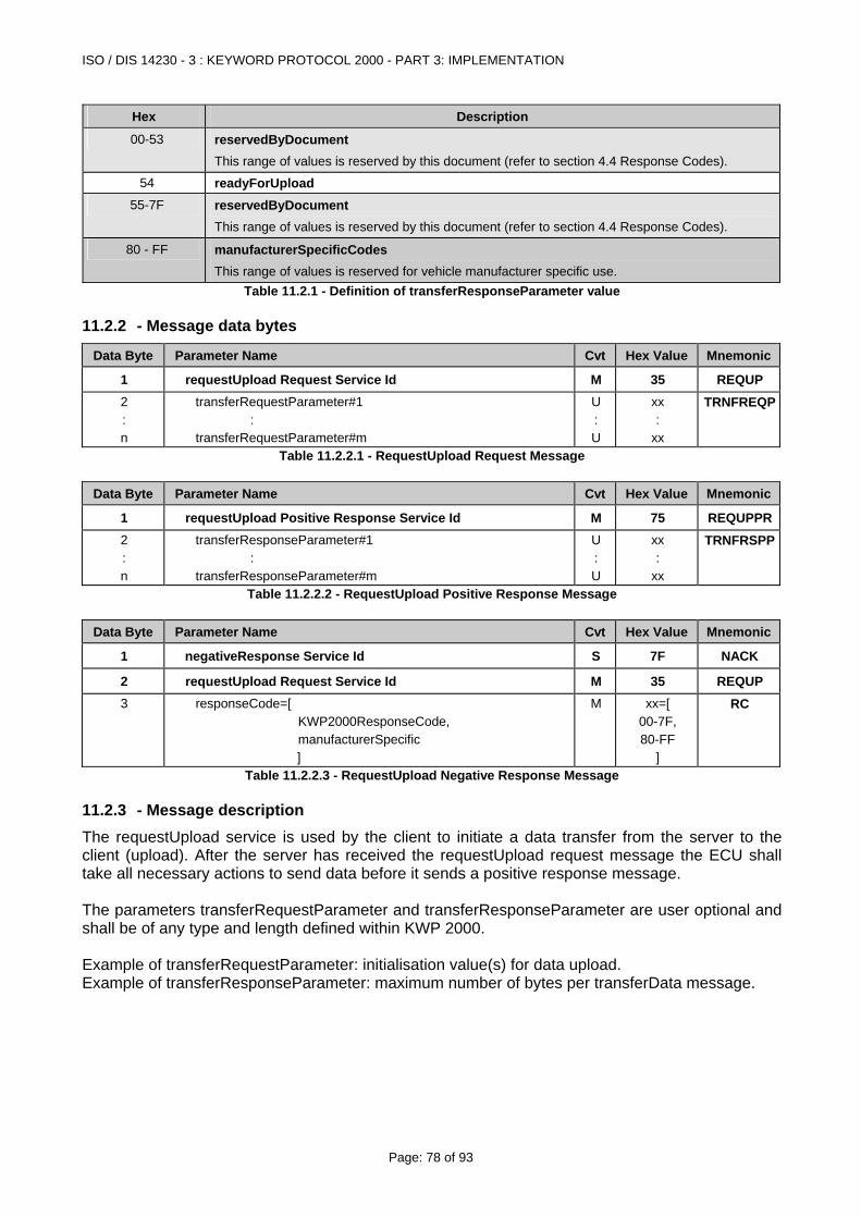
ISO / DIS 14230 - 3 : KEYWORD PROTOCOL 2000 - PART 3: IMPLEMENTATION
Page: 78 of 93
Hex Description
00-53 reservedByDocument This range of values is reserved by this document (refer to section 4.4 Response Codes).
54 readyForUpload
55-7F reservedByDocument This range of values is reserved by this document (refer to section 4.4 Response Codes).
80 - FF manufacturerSpecificCodes This range of values is reserved for vehicle manufacturer specific use.
Table 11.2.1 - Definition of transferResponseParameter value
11.2.2 - Message data bytes
Data Byte Parameter Name Cvt Hex Value Mnemonic
1 requestUpload Request Service Id M 35 REQUP 2 : n
transferRequestParameter#1 : transferRequestParameter#m
U : U
xx :
xx
TRNFREQP
Table 11.2.2.1 - RequestUpload Request Message
Data Byte Parameter Name Cvt Hex Value Mnemonic
1 requestUpload Positive Response Service Id M 75 REQUPPR2 : n
transferResponseParameter#1 : transferResponseParameter#m
U : U
xx :
xx
TRNFRSPP
Table 11.2.2.2 - RequestUpload Positive Response Message
Data Byte Parameter Name Cvt Hex Value Mnemonic
1 negativeResponse Service Id S 7F NACK
2 requestUpload Request Service Id M 35 REQUP 3 responseCode=[
KWP2000ResponseCode, manufacturerSpecific ]
M xx=[ 00-7F, 80-FF
]
RC
Table 11.2.2.3 - RequestUpload Negative Response Message
11.2.3 - Message description The requestUpload service is used by the client to initiate a data transfer from the server to the client (upload). After the server has received the requestUpload request message the ECU shall take all necessary actions to send data before it sends a positive response message. The parameters transferRequestParameter and transferResponseParameter are user optional and shall be of any type and length defined within KWP 2000. Example of transferRequestParameter: initialisation value(s) for data upload. Example of transferResponseParameter: maximum number of bytes per transferData message.
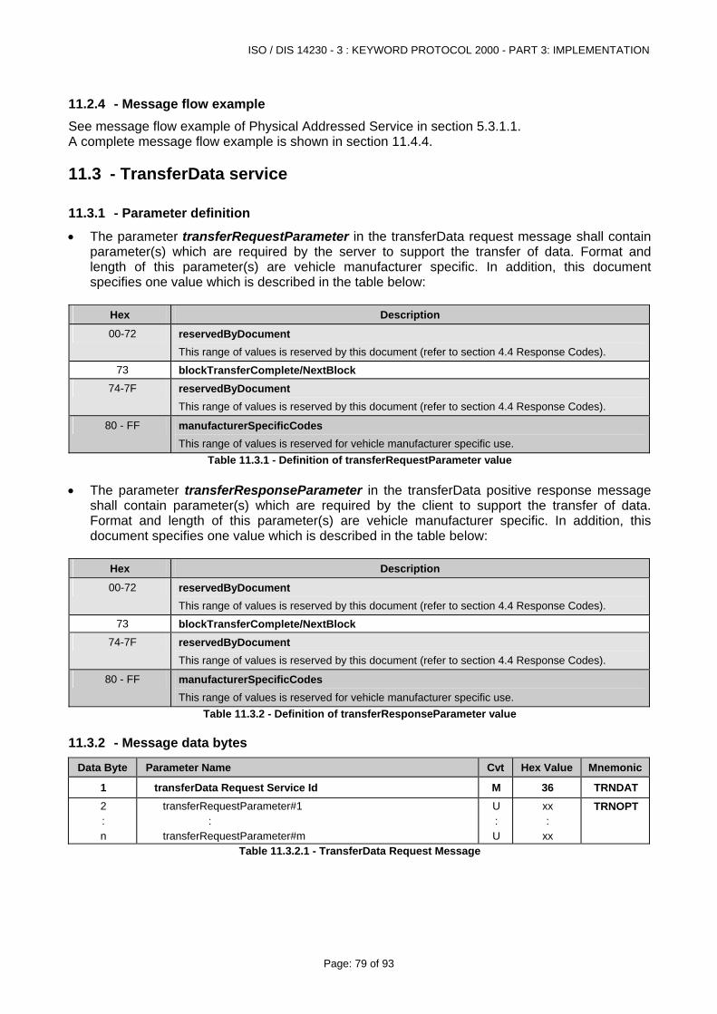
ISO / DIS 14230 - 3 : KEYWORD PROTOCOL 2000 - PART 3: IMPLEMENTATION
Page: 79 of 93
11.2.4 - Message flow example See message flow example of Physical Addressed Service in section 5.3.1.1. A complete message flow example is shown in section 11.4.4.
11.3 - TransferData service
11.3.1 - Parameter definition
• The parameter transferRequestParameter in the transferData request message shall contain parameter(s) which are required by the server to support the transfer of data. Format and length of this parameter(s) are vehicle manufacturer specific. In addition, this document specifies one value which is described in the table below:
Hex Description
00-72 reservedByDocument This range of values is reserved by this document (refer to section 4.4 Response Codes).
73 blockTransferComplete/NextBlock
74-7F reservedByDocument This range of values is reserved by this document (refer to section 4.4 Response Codes).
80 - FF manufacturerSpecificCodes This range of values is reserved for vehicle manufacturer specific use.
Table 11.3.1 - Definition of transferRequestParameter value • The parameter transferResponseParameter in the transferData positive response message
shall contain parameter(s) which are required by the client to support the transfer of data. Format and length of this parameter(s) are vehicle manufacturer specific. In addition, this document specifies one value which is described in the table below:
Hex Description
00-72 reservedByDocument This range of values is reserved by this document (refer to section 4.4 Response Codes).
73 blockTransferComplete/NextBlock
74-7F reservedByDocument This range of values is reserved by this document (refer to section 4.4 Response Codes).
80 - FF manufacturerSpecificCodes This range of values is reserved for vehicle manufacturer specific use.
Table 11.3.2 - Definition of transferResponseParameter value
11.3.2 - Message data bytes
Data Byte Parameter Name Cvt Hex Value Mnemonic
1 transferData Request Service Id M 36 TRNDAT2 : n
transferRequestParameter#1 : transferRequestParameter#m
U : U
xx :
xx
TRNOPT
Table 11.3.2.1 - TransferData Request Message
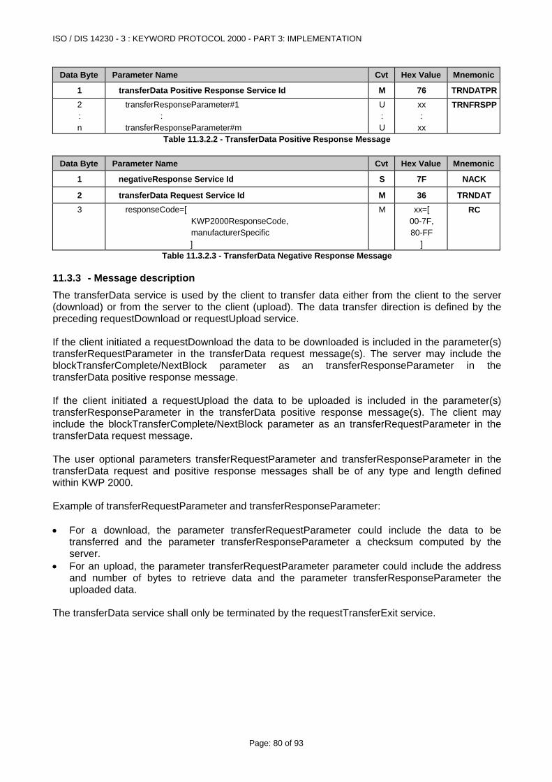
ISO / DIS 14230 - 3 : KEYWORD PROTOCOL 2000 - PART 3: IMPLEMENTATION
Page: 80 of 93
Data Byte Parameter Name Cvt Hex Value Mnemonic
1 transferData Positive Response Service Id M 76 TRNDATPR2 : n
transferResponseParameter#1 : transferResponseParameter#m
U : U
xx :
xx
TRNFRSPP
Table 11.3.2.2 - TransferData Positive Response Message
Data Byte Parameter Name Cvt Hex Value Mnemonic
1 negativeResponse Service Id S 7F NACK
2 transferData Request Service Id M 36 TRNDAT3 responseCode=[
KWP2000ResponseCode, manufacturerSpecific ]
M xx=[ 00-7F, 80-FF
]
RC
Table 11.3.2.3 - TransferData Negative Response Message
11.3.3 - Message description The transferData service is used by the client to transfer data either from the client to the server (download) or from the server to the client (upload). The data transfer direction is defined by the preceding requestDownload or requestUpload service. If the client initiated a requestDownload the data to be downloaded is included in the parameter(s) transferRequestParameter in the transferData request message(s). The server may include the blockTransferComplete/NextBlock parameter as an transferResponseParameter in the transferData positive response message. If the client initiated a requestUpload the data to be uploaded is included in the parameter(s) transferResponseParameter in the transferData positive response message(s). The client may include the blockTransferComplete/NextBlock parameter as an transferRequestParameter in the transferData request message. The user optional parameters transferRequestParameter and transferResponseParameter in the transferData request and positive response messages shall be of any type and length defined within KWP 2000. Example of transferRequestParameter and transferResponseParameter: • For a download, the parameter transferRequestParameter could include the data to be
transferred and the parameter transferResponseParameter a checksum computed by the server.
• For an upload, the parameter transferRequestParameter parameter could include the address and number of bytes to retrieve data and the parameter transferResponseParameter the uploaded data.
The transferData service shall only be terminated by the requestTransferExit service.
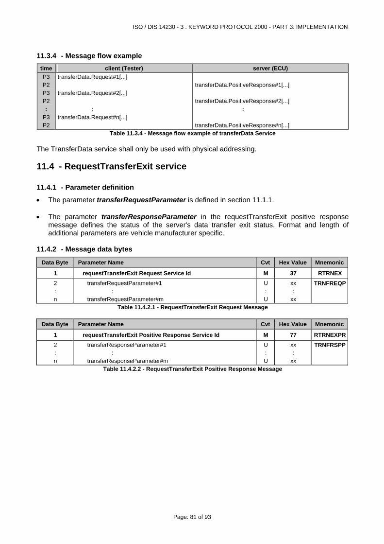
ISO / DIS 14230 - 3 : KEYWORD PROTOCOL 2000 - PART 3: IMPLEMENTATION
Page: 81 of 93
11.3.4 - Message flow example time client (Tester) server (ECU) P3 P2 P3 P2 :
P3 P2
transferData.Request#1[...] transferData.Request#2[...] : transferData.Request#n[...]
transferData.PositiveResponse#1[...] transferData.PositiveResponse#2[...] : transferData.PositiveResponse#n[...]
Table 11.3.4 - Message flow example of transferData Service The TransferData service shall only be used with physical addressing.
11.4 - RequestTransferExit service
11.4.1 - Parameter definition
• The parameter transferRequestParameter is defined in section 11.1.1. • The parameter transferResponseParameter in the requestTransferExit positive response
message defines the status of the server's data transfer exit status. Format and length of additional parameters are vehicle manufacturer specific.
11.4.2 - Message data bytes
Data Byte Parameter Name Cvt Hex Value Mnemonic
1 requestTransferExit Request Service Id M 37 RTRNEX2 : n
transferRequestParameter#1 : transferRequestParameter#m
U : U
xx :
xx
TRNFREQP
Table 11.4.2.1 - RequestTransferExit Request Message
Data Byte Parameter Name Cvt Hex Value Mnemonic
1 requestTransferExit Positive Response Service Id M 77 RTRNEXPR2 : n
transferResponseParameter#1 : transferResponseParameter#m
U : U
xx :
xx
TRNFRSPP
Table 11.4.2.2 - RequestTransferExit Positive Response Message
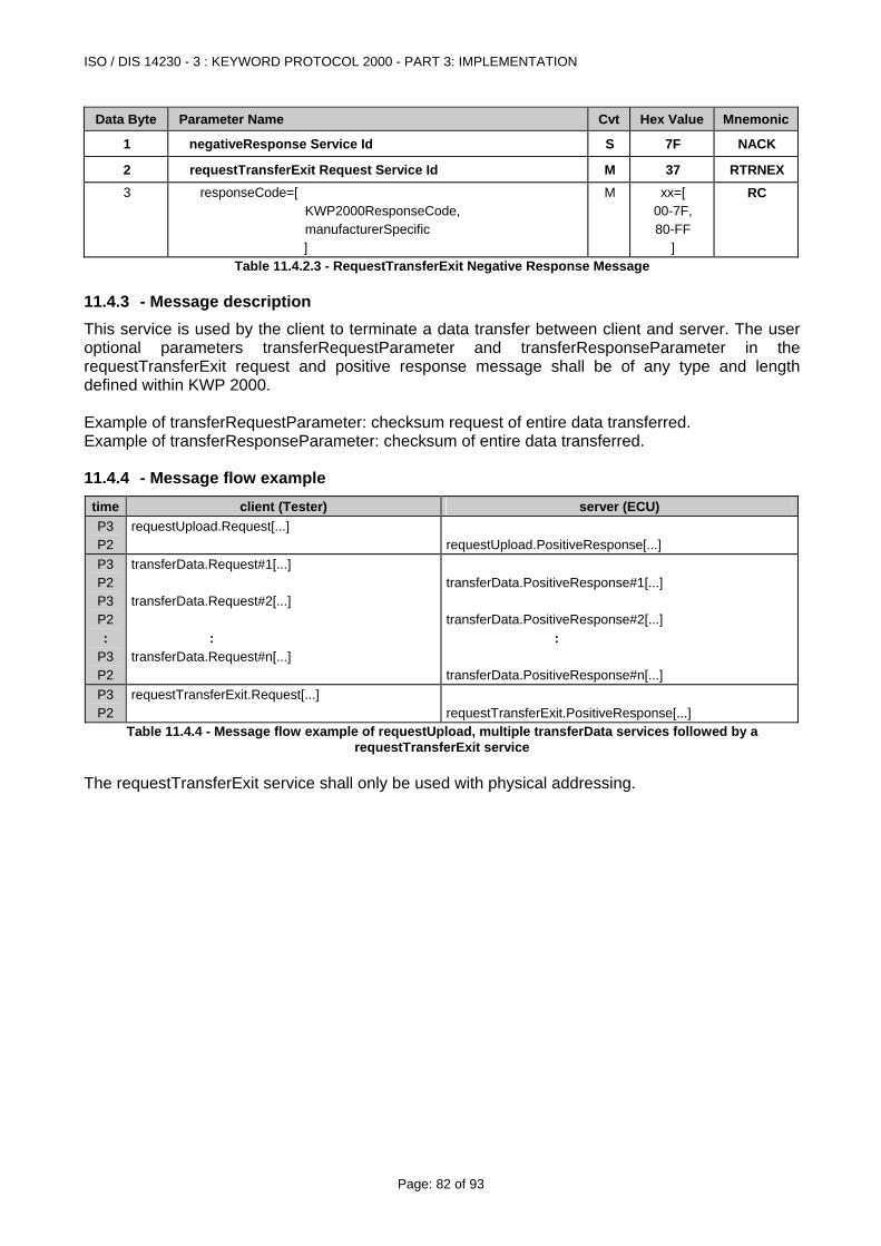
ISO / DIS 14230 - 3 : KEYWORD PROTOCOL 2000 - PART 3: IMPLEMENTATION
Page: 82 of 93
Data Byte Parameter Name Cvt Hex Value Mnemonic
1 negativeResponse Service Id S 7F NACK
2 requestTransferExit Request Service Id M 37 RTRNEX3 responseCode=[
KWP2000ResponseCode, manufacturerSpecific ]
M xx=[ 00-7F, 80-FF
]
RC
Table 11.4.2.3 - RequestTransferExit Negative Response Message
11.4.3 - Message description This service is used by the client to terminate a data transfer between client and server. The user optional parameters transferRequestParameter and transferResponseParameter in the requestTransferExit request and positive response message shall be of any type and length defined within KWP 2000. Example of transferRequestParameter: checksum request of entire data transferred. Example of transferResponseParameter: checksum of entire data transferred.
11.4.4 - Message flow example time client (Tester) server (ECU) P3 P2
requestUpload.Request[...]
requestUpload.PositiveResponse[...]
P3 P2 P3 P2 :
P3 P2
transferData.Request#1[...] transferData.Request#2[...] : transferData.Request#n[...]
transferData.PositiveResponse#1[...] transferData.PositiveResponse#2[...] : transferData.PositiveResponse#n[...]
P3 P2
requestTransferExit.Request[...]
requestTransferExit.PositiveResponse[...]
Table 11.4.4 - Message flow example of requestUpload, multiple transferData services followed by a requestTransferExit service
The requestTransferExit service shall only be used with physical addressing.
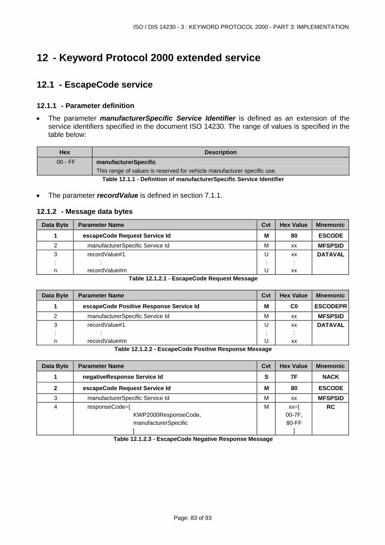
ISO / DIS 14230 - 3 : KEYWORD PROTOCOL 2000 - PART 3: IMPLEMENTATION
Page: 83 of 93
12 - Keyword Protocol 2000 extended service
12.1 - EscapeCode service
12.1.1 - Parameter definition
• The parameter manufacturerSpecific Service Identifier is defined as an extension of the service identifiers specified in the document ISO 14230. The range of values is specified in the table below:
Hex Description
00 - FF manufacturerSpecific This range of values is reserved for vehicle manufacturer specific use.
Table 12.1.1 - Definition of manufacturerSpecific Service Identifier • The parameter recordValue is defined in section 7.1.1.
12.1.2 - Message data bytes
Data Byte Parameter Name Cvt Hex Value Mnemonic
1 escapeCode Request Service Id M 80 ESCODE2 manufacturerSpecific Service Id M xx MFSPSID3 : n
recordValue#1 : recordValue#m
U : U
xx :
xx
DATAVAL
Table 12.1.2.1 - EscapeCode Request Message
Data Byte Parameter Name Cvt Hex Value Mnemonic
1 escapeCode Positive Response Service Id M C0 ESCODEPR2 manufacturerSpecific Service Id M xx MFSPSID3 : n
recordValue#1 : recordValue#m
U : U
xx :
xx
DATAVAL
Table 12.1.2.2 - EscapeCode Positive Response Message
Data Byte Parameter Name Cvt Hex Value Mnemonic
1 negativeResponse Service Id S 7F NACK
2 escapeCode Request Service Id M 80 ESCODE3 manufacturerSpecific Service Id M xx MFSPSID4 responseCode=[
KWP2000ResponseCode, manufacturerSpecific ]
M xx=[ 00-7F, 80-FF
]
RC
Table 12.1.2.3 - EscapeCode Negative Response Message
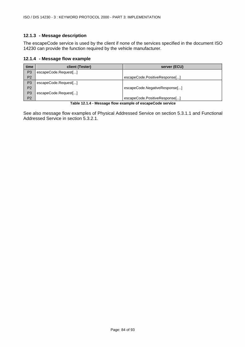
ISO / DIS 14230 - 3 : KEYWORD PROTOCOL 2000 - PART 3: IMPLEMENTATION
Page: 84 of 93
12.1.3 - Message description The escapeCode service is used by the client if none of the services specified in the document ISO 14230 can provide the function required by the vehicle manufacturer.
12.1.4 - Message flow example time client (Tester) server (ECU) P3 P2
escapeCode.Request[...] escapeCode.PositiveResponse[...]
P3 P2 P3 P2
escapeCode.Request[...] escapeCode.Request[...]
escapeCode.NegativeResponse[...] escapeCode.PositiveResponse[...]
Table 12.1.4 - Message flow example of escapeCode service See also message flow examples of Physical Addressed Service on section 5.3.1.1 and Functional Addressed Service in section 5.3.2.1.
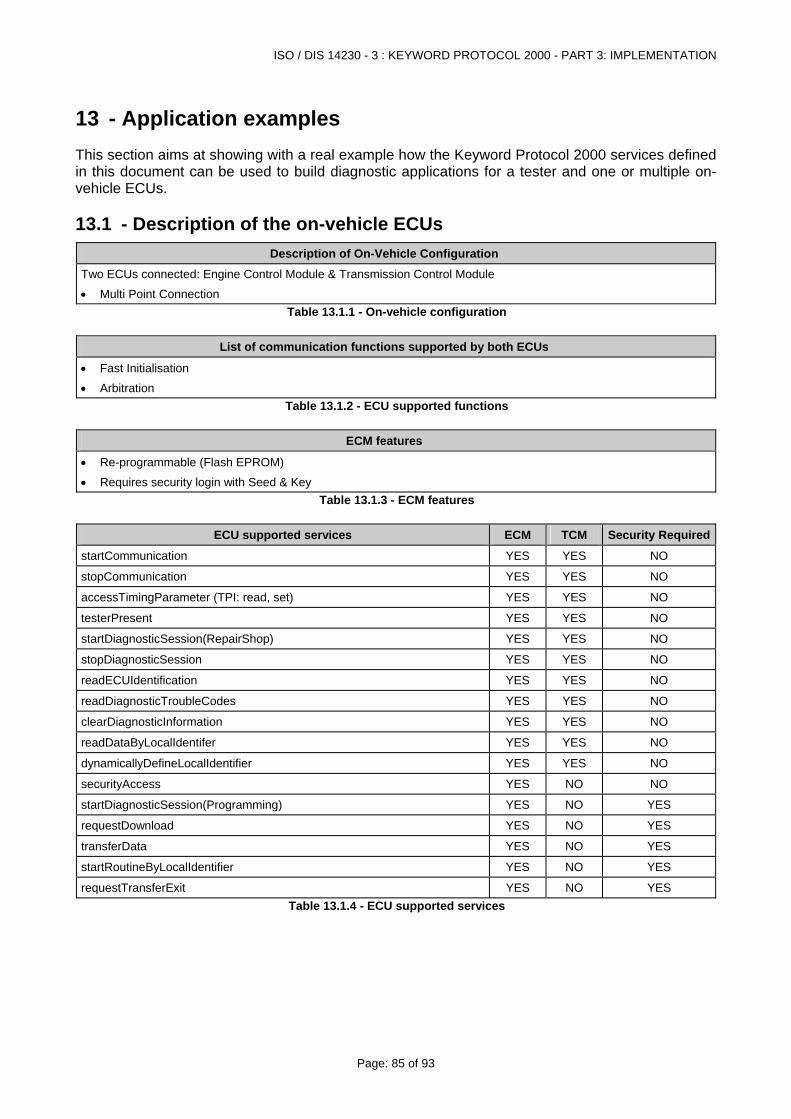
ISO / DIS 14230 - 3 : KEYWORD PROTOCOL 2000 - PART 3: IMPLEMENTATION
Page: 85 of 93
13 - Application examples This section aims at showing with a real example how the Keyword Protocol 2000 services defined in this document can be used to build diagnostic applications for a tester and one or multiple on-vehicle ECUs.
13.1 - Description of the on-vehicle ECUs Description of On-Vehicle Configuration
Two ECUs connected: Engine Control Module & Transmission Control Module
• Multi Point Connection Table 13.1.1 - On-vehicle configuration
List of communication functions supported by both ECUs
• Fast Initialisation
• Arbitration Table 13.1.2 - ECU supported functions
ECM features
• Re-programmable (Flash EPROM)
• Requires security login with Seed & Key Table 13.1.3 - ECM features
ECU supported services ECM TCM Security Required
startCommunication YES YES NO
stopCommunication YES YES NO
accessTimingParameter (TPI: read, set) YES YES NO
testerPresent YES YES NO
startDiagnosticSession(RepairShop) YES YES NO
stopDiagnosticSession YES YES NO
readECUIdentification YES YES NO
readDiagnosticTroubleCodes YES YES NO
clearDiagnosticInformation YES YES NO
readDataByLocalIdentifer YES YES NO
dynamicallyDefineLocalIdentifier YES YES NO
securityAccess YES NO NO
startDiagnosticSession(Programming) YES NO YES
requestDownload YES NO YES
transferData YES NO YES
startRoutineByLocalIdentifier YES NO YES
requestTransferExit YES NO YES Table 13.1.4 - ECU supported services
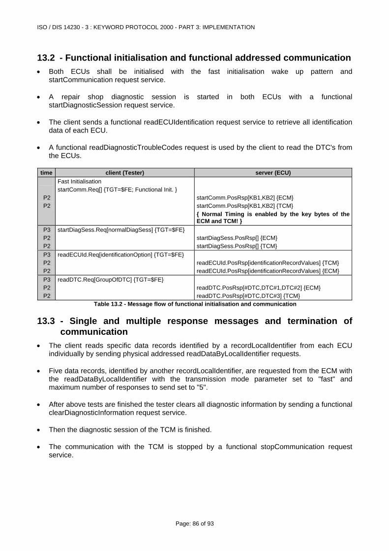
ISO / DIS 14230 - 3 : KEYWORD PROTOCOL 2000 - PART 3: IMPLEMENTATION
Page: 86 of 93
13.2 - Functional initialisation and functional addressed communication • Both ECUs shall be initialised with the fast initialisation wake up pattern and
startCommunication request service. • A repair shop diagnostic session is started in both ECUs with a functional
startDiagnosticSession request service. • The client sends a functional readECUIdentification request service to retrieve all identification
data of each ECU. • A functional readDiagnosticTroubleCodes request is used by the client to read the DTC's from
the ECUs.
time client (Tester) server (ECU)
P2 P2
Fast Initialisation startComm.Req[] {TGT=$FE; Functional Init. }
startComm.PosRsp[KB1,KB2] {ECM} startComm.PosRsp[KB1,KB2] {TCM} { Normal Timing is enabled by the key bytes of the ECM and TCM! }
P3 P2 P2
startDiagSess.Req[normalDiagSess] {TGT=$FE} startDiagSess.PosRsp[] {ECM} startDiagSess.PosRsp[] {TCM}
P3 P2 P2
readECUId.Req[identificationOption] {TGT=$FE} readECUId.PosRsp[identificationRecordValues] {TCM} readECUId.PosRsp[identificationRecordValues] {ECM}
P3 P2 P2
readDTC.Req[GroupOfDTC] {TGT=$FE} readDTC.PosRsp[#DTC,DTC#1,DTC#2] {ECM} readDTC.PosRsp[#DTC,DTC#3] {TCM}
Table 13.2 - Message flow of functional initialisation and communication
13.3 - Single and multiple response messages and termination of communication
• The client reads specific data records identified by a recordLocalIdentifier from each ECU individually by sending physical addressed readDataByLocalIdentifier requests.
• Five data records, identified by another recordLocalIdentifier, are requested from the ECM with
the readDataByLocalIdentifier with the transmission mode parameter set to "fast" and maximum number of responses to send set to "5".
• After above tests are finished the tester clears all diagnostic information by sending a functional
clearDiagnosticInformation request service. • Then the diagnostic session of the TCM is finished. • The communication with the TCM is stopped by a functional stopCommunication request
service.
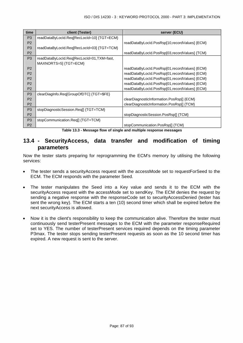
ISO / DIS 14230 - 3 : KEYWORD PROTOCOL 2000 - PART 3: IMPLEMENTATION
Page: 87 of 93
time client (Tester) server (ECU) P3 P2 P3 P2
readDataByLocId.Req[RecLocId=10] {TGT=ECM} readDataByLocId.Req[RecLocId=03] {TGT=TCM}
readDataByLocId.PosRsp[10,recordValues] {ECM} readDataByLocId.PosRsp[03,recordValues] {TCM}
P3
P2 P2 P2 P2 P2
readDataByLocId.Req[RecLocId=01,TXM=fast, MAXNORTS=5] {TGT=ECM}
readDataByLocId.PosRsp[01,recordValues] {ECM} readDataByLocId.PosRsp[01,recordValues] {ECM} readDataByLocId.PosRsp[01,recordValues] {ECM} readDataByLocId.PosRsp[01,recordValues] {ECM} readDataByLocId.PosRsp[01,recordValues] {ECM}
P3 P2 P2
clearDiagInfo.Req[GroupOfDTC] {TGT=$FE}
clearDiagnosticInformation.PosRsp[] {ECM} clearDiagnosticInformation.PosRsp[] {TCM}
P3 P2
stopDiagnosticSession.Req[] {TGT=TCM}
stopDiagnosticSession.PosRsp[] {TCM}
P3 P2
stopCommunication.Req[] {TGT=TCM}
stopCommunication.PosRsp[] {TCM}
Table 13.3 - Message flow of single and multiple response messages
13.4 - SecurityAccess, data transfer and modification of timing parameters
Now the tester starts preparing for reprogramming the ECM's memory by utilising the following services: • The tester sends a securityAccess request with the accessMode set to requestForSeed to the
ECM. The ECM responds with the parameter Seed. • The tester manipulates the Seed into a Key value and sends it to the ECM with the
securityAccess request with the accessMode set to sendKey. The ECM denies the request by sending a negative response with the responseCode set to securityAccessDenied (tester has sent the wrong key). The ECM starts a ten (10) second timer which shall be expired before the next securityAccess is allowed.
• Now it is the client's responsibility to keep the communication alive. Therefore the tester must
continuously send testerPresent messages to the ECM with the parameter responseRequired set to YES. The number of testerPresent services required depends on the timing parameter P3max. The tester stops sending testerPresent requests as soon as the 10 second timer has expired. A new request is sent to the server.
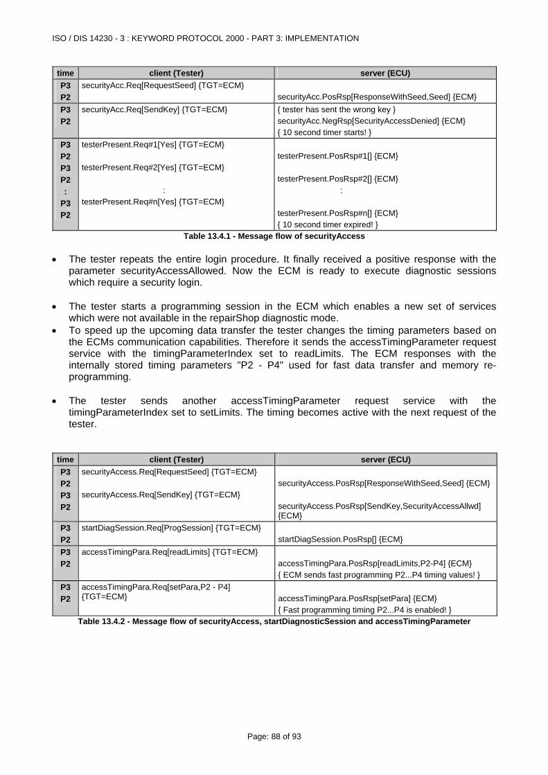
ISO / DIS 14230 - 3 : KEYWORD PROTOCOL 2000 - PART 3: IMPLEMENTATION
Page: 88 of 93
time client (Tester) server (ECU) P3 P2
securityAcc.Req[RequestSeed] {TGT=ECM}
securityAcc.PosRsp[ResponseWithSeed,Seed] {ECM}
P3 P2
securityAcc.Req[SendKey] {TGT=ECM}
{ tester has sent the wrong key } securityAcc.NegRsp[SecurityAccessDenied] {ECM} { 10 second timer starts! }
P3 P2 P3 P2 :
P3 P2
testerPresent.Req#1[Yes] {TGT=ECM} testerPresent.Req#2[Yes] {TGT=ECM} : testerPresent.Req#n[Yes] {TGT=ECM}
testerPresent.PosRsp#1[] {ECM} testerPresent.PosRsp#2[] {ECM} : testerPresent.PosRsp#n[] {ECM} { 10 second timer expired! }
Table 13.4.1 - Message flow of securityAccess • The tester repeats the entire login procedure. It finally received a positive response with the
parameter securityAccessAllowed. Now the ECM is ready to execute diagnostic sessions which require a security login.
• The tester starts a programming session in the ECM which enables a new set of services
which were not available in the repairShop diagnostic mode. • To speed up the upcoming data transfer the tester changes the timing parameters based on
the ECMs communication capabilities. Therefore it sends the accessTimingParameter request service with the timingParameterIndex set to readLimits. The ECM responses with the internally stored timing parameters "P2 - P4" used for fast data transfer and memory re-programming.
• The tester sends another accessTimingParameter request service with the
timingParameterIndex set to setLimits. The timing becomes active with the next request of the tester.
time client (Tester) server (ECU) P3 P2 P3 P2
securityAccess.Req[RequestSeed] {TGT=ECM} securityAccess.Req[SendKey] {TGT=ECM}
securityAccess.PosRsp[ResponseWithSeed,Seed] {ECM} securityAccess.PosRsp[SendKey,SecurityAccessAllwd] {ECM}
P3 P2
startDiagSession.Req[ProgSession] {TGT=ECM}
startDiagSession.PosRsp[] {ECM}
P3 P2
accessTimingPara.Req[readLimits] {TGT=ECM}
accessTimingPara.PosRsp[readLimits,P2-P4] {ECM} { ECM sends fast programming P2...P4 timing values! }
P3 P2
accessTimingPara.Req[setPara,P2 - P4] {TGT=ECM}
accessTimingPara.PosRsp[setPara] {ECM} { Fast programming timing P2...P4 is enabled! }
Table 13.4.2 - Message flow of securityAccess, startDiagnosticSession and accessTimingParameter
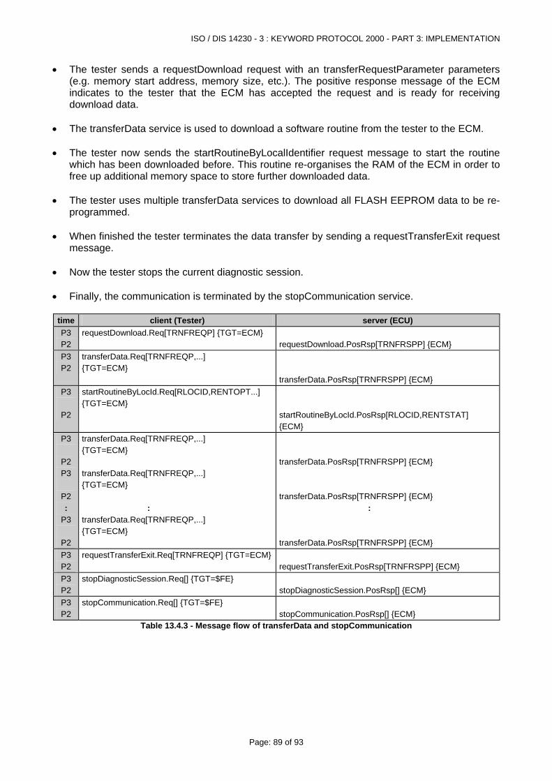
ISO / DIS 14230 - 3 : KEYWORD PROTOCOL 2000 - PART 3: IMPLEMENTATION
Page: 89 of 93
• The tester sends a requestDownload request with an transferRequestParameter parameters (e.g. memory start address, memory size, etc.). The positive response message of the ECM indicates to the tester that the ECM has accepted the request and is ready for receiving download data.
• The transferData service is used to download a software routine from the tester to the ECM. • The tester now sends the startRoutineByLocalIdentifier request message to start the routine
which has been downloaded before. This routine re-organises the RAM of the ECM in order to free up additional memory space to store further downloaded data.
• The tester uses multiple transferData services to download all FLASH EEPROM data to be re-
programmed. • When finished the tester terminates the data transfer by sending a requestTransferExit request
message. • Now the tester stops the current diagnostic session. • Finally, the communication is terminated by the stopCommunication service.
time client (Tester) server (ECU) P3 P2
requestDownload.Req[TRNFREQP] {TGT=ECM} requestDownload.PosRsp[TRNFRSPP] {ECM}
P3 P2
transferData.Req[TRNFREQP,...] {TGT=ECM}
transferData.PosRsp[TRNFRSPP] {ECM}
P3
P2
startRoutineByLocId.Req[RLOCID,RENTOPT...] {TGT=ECM}
startRoutineByLocId.PosRsp[RLOCID,RENTSTAT] {ECM}
P3
P2 P3
P2 :
P3
P2
transferData.Req[TRNFREQP,...] {TGT=ECM} transferData.Req[TRNFREQP,...] {TGT=ECM} : transferData.Req[TRNFREQP,...] {TGT=ECM}
transferData.PosRsp[TRNFRSPP] {ECM} transferData.PosRsp[TRNFRSPP] {ECM} : transferData.PosRsp[TRNFRSPP] {ECM}
P3 P2
requestTransferExit.Req[TRNFREQP] {TGT=ECM}
requestTransferExit.PosRsp[TRNFRSPP] {ECM}
P3 P2
stopDiagnosticSession.Req[] {TGT=$FE}
stopDiagnosticSession.PosRsp[] {ECM}
P3 P2
stopCommunication.Req[] {TGT=$FE}
stopCommunication.PosRsp[] {ECM}
Table 13.4.3 - Message flow of transferData and stopCommunication
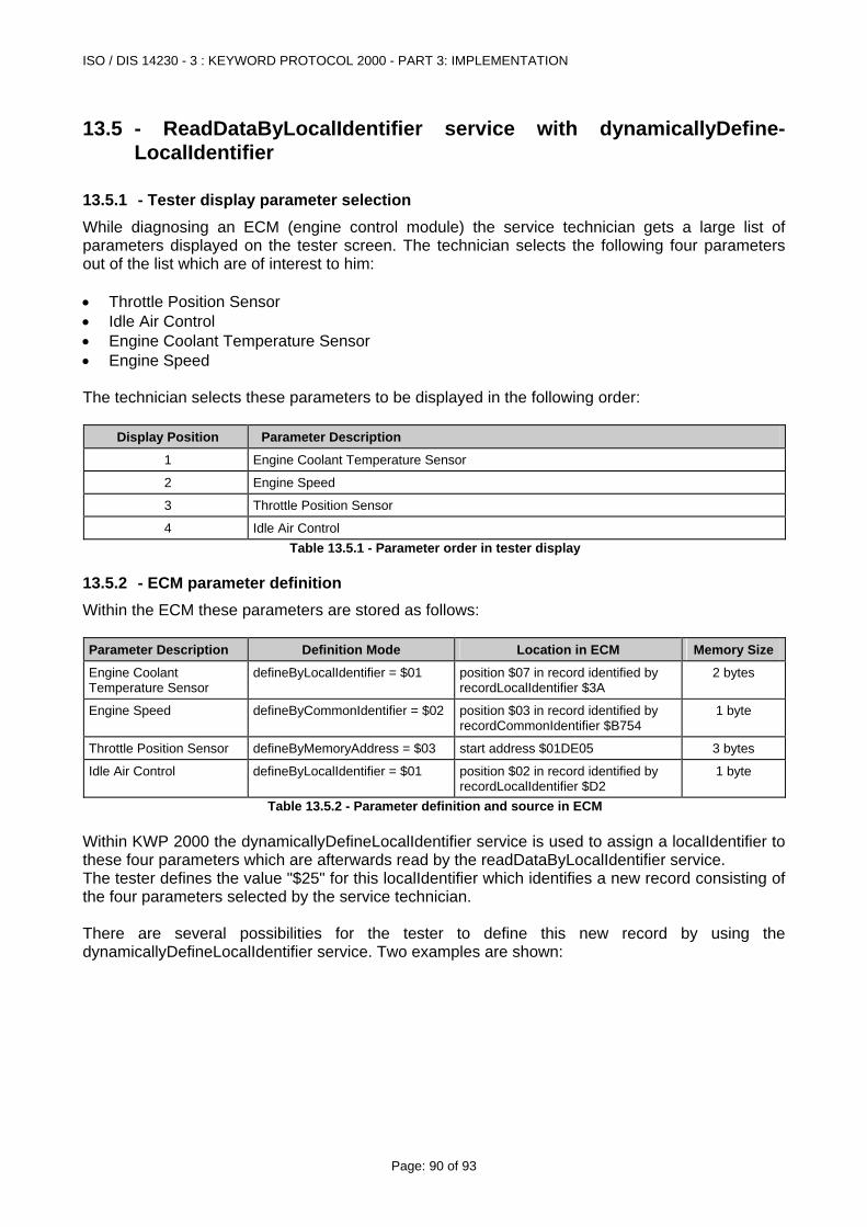
ISO / DIS 14230 - 3 : KEYWORD PROTOCOL 2000 - PART 3: IMPLEMENTATION
Page: 90 of 93
13.5 - ReadDataByLocalIdentifier service with dynamicallyDefine-LocalIdentifier
13.5.1 - Tester display parameter selection While diagnosing an ECM (engine control module) the service technician gets a large list of parameters displayed on the tester screen. The technician selects the following four parameters out of the list which are of interest to him: • Throttle Position Sensor • Idle Air Control • Engine Coolant Temperature Sensor • Engine Speed The technician selects these parameters to be displayed in the following order:
Display Position Parameter Description
1 Engine Coolant Temperature Sensor
2 Engine Speed
3 Throttle Position Sensor
4 Idle Air Control Table 13.5.1 - Parameter order in tester display
13.5.2 - ECM parameter definition Within the ECM these parameters are stored as follows: Parameter Description Definition Mode Location in ECM Memory Size
Engine Coolant Temperature Sensor
defineByLocalIdentifier = $01 position $07 in record identified by recordLocalIdentifier $3A
2 bytes
Engine Speed defineByCommonIdentifier = $02 position $03 in record identified by recordCommonIdentifier $B754
1 byte
Throttle Position Sensor defineByMemoryAddress = $03 start address $01DE05 3 bytes
Idle Air Control defineByLocalIdentifier = $01 position $02 in record identified by recordLocalIdentifier $D2
1 byte
Table 13.5.2 - Parameter definition and source in ECM Within KWP 2000 the dynamicallyDefineLocalIdentifier service is used to assign a localIdentifier to these four parameters which are afterwards read by the readDataByLocalIdentifier service. The tester defines the value "$25" for this localIdentifier which identifies a new record consisting of the four parameters selected by the service technician. There are several possibilities for the tester to define this new record by using the dynamicallyDefineLocalIdentifier service. Two examples are shown:
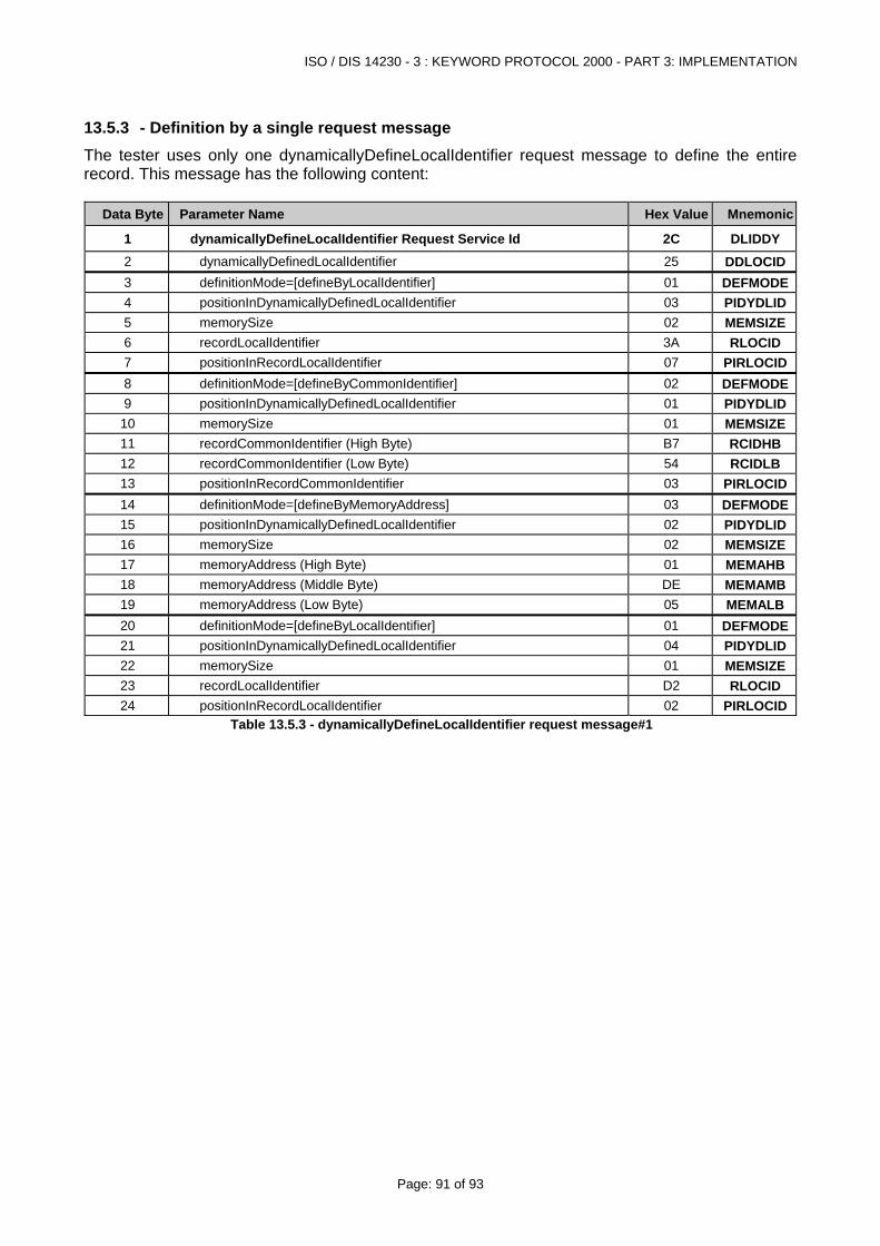
ISO / DIS 14230 - 3 : KEYWORD PROTOCOL 2000 - PART 3: IMPLEMENTATION
Page: 91 of 93
13.5.3 - Definition by a single request message The tester uses only one dynamicallyDefineLocalIdentifier request message to define the entire record. This message has the following content:
Data Byte Parameter Name Hex Value Mnemonic
1 dynamicallyDefineLocalIdentifier Request Service Id 2C DLIDDY 2 dynamicallyDefinedLocalIdentifier 25 DDLOCID3 definitionMode=[defineByLocalIdentifier] 01 DEFMODE4 positionInDynamicallyDefinedLocalIdentifier 03 PIDYDLID5 memorySize 02 MEMSIZE6 recordLocalIdentifier 3A RLOCID 7 positionInRecordLocalIdentifier 07 PIRLOCID8 definitionMode=[defineByCommonIdentifier] 02 DEFMODE9 positionInDynamicallyDefinedLocalIdentifier 01 PIDYDLID
10 memorySize 01 MEMSIZE11 recordCommonIdentifier (High Byte) B7 RCIDHB 12 recordCommonIdentifier (Low Byte) 54 RCIDLB 13 positionInRecordCommonIdentifier 03 PIRLOCID14 definitionMode=[defineByMemoryAddress] 03 DEFMODE15 positionInDynamicallyDefinedLocalIdentifier 02 PIDYDLID16 memorySize 02 MEMSIZE17 memoryAddress (High Byte) 01 MEMAHB18 memoryAddress (Middle Byte) DE MEMAMB19 memoryAddress (Low Byte) 05 MEMALB20 definitionMode=[defineByLocalIdentifier] 01 DEFMODE21 positionInDynamicallyDefinedLocalIdentifier 04 PIDYDLID22 memorySize 01 MEMSIZE23 recordLocalIdentifier D2 RLOCID 24 positionInRecordLocalIdentifier 02 PIRLOCID
Table 13.5.3 - dynamicallyDefineLocalIdentifier request message#1
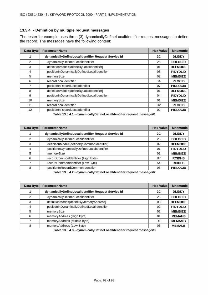
ISO / DIS 14230 - 3 : KEYWORD PROTOCOL 2000 - PART 3: IMPLEMENTATION
Page: 92 of 93
13.5.4 - Definition by multiple request messages The tester for example uses three (3) dynamicallyDefineLocalIdentifier request messages to define the record. The messages have the following content:
Data Byte Parameter Name Hex Value Mnemonic
1 dynamicallyDefineLocalIdentifier Request Service Id 2C DLIDDY 2 dynamicallyDefinedLocalIdentifier 25 DDLOCID3 definitionMode=[defineByLocalIdentifier] 01 DEFMODE4 positionInDynamicallyDefinedLocalIdentifier 03 PIDYDLID5 memorySize 02 MEMSIZE6 recordLocalIdentifier 3A RLOCID 7 positionInRecordLocalIdentifier 07 PIRLOCID8 definitionMode=[defineByLocalIdentifier] 01 DEFMODE9 positionInDynamicallyDefinedLocalIdentifier 04 PIDYDLID
10 memorySize 01 MEMSIZE11 recordLocalIdentifier D2 RLOCID 12 positionInRecordLocalIdentifier 02 PIRLOCID
Table 13.5.4.1 - dynamicallyDefineLocalIdentifier request message#1
Data Byte Parameter Name Hex Value Mnemonic
1 dynamicallyDefineLocalIdentifier Request Service Id 2C DLIDDY 2 dynamicallyDefinedLocalIdentifier 25 DDLOCID3 definitionMode=[defineByCommonIdentifier] 02 DEFMODE4 positionInDynamicallyDefinedLocalIdentifier 01 PIDYDLID5 memorySize 01 MEMSIZE6 recordCommonIdentifier (High Byte) B7 RCIDHB 7 recordCommonIdentifier (Low Byte) 54 RCIDLB 8 positionInRecordCommonIdentifier 03 PIRLOCID
Table 13.5.4.2 - dynamicallyDefineLocalIdentifier request message#2
Data Byte Parameter Name Hex Value Mnemonic
1 dynamicallyDefineLocalIdentifier Request Service Id 2C DLIDDY 2 dynamicallyDefinedLocalIdentifier 25 DDLOCID3 definitionMode=[defineByMemoryAddress] 03 DEFMODE4 positionInDynamicallyDefinedLocalIdentifier 02 PIDYDLID5 memorySize 02 MEMSIZE6 memoryAddress (High Byte) 01 MEMAHB7 memoryAddress (Middle Byte) DE MEMAMB8 memoryAddress (Low Byte) 05 MEMALB
Table 13.5.4.3 - dynamicallyDefineLocalIdentifier request message#3
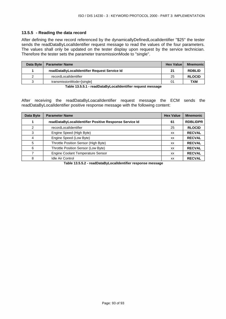
ISO / DIS 14230 - 3 : KEYWORD PROTOCOL 2000 - PART 3: IMPLEMENTATION
Page: 93 of 93
13.5.5 - Reading the data record After defining the new record referenced by the dynamicallyDefinedLocalIdentifier "$25" the tester sends the readDataByLocalIdentifier request message to read the values of the four parameters. The values shall only be updated on the tester display upon request by the service technician. Therefore the tester sets the parameter transmissionMode to "single".
Data Byte Parameter Name Hex Value Mnemonic
1 readDataByLocalIdentifier Request Service Id 21 RDBLID 2 recordLocalIdentifier 25 RLOCID 3 transmissionMode=[single] 01 TXM
Table 13.5.5.1 - readDataByLocalIdentifier request message After receiving the readDataByLoacalIdentifier request message the ECM sends the readDataByLocalIdentifier positive response message with the following content:
Data Byte Parameter Name Hex Value Mnemonic
1 readDataByLocalIdentifier Positive Response Service Id 61 RDBLIDPR2 recordLocalIdentifier 25 RLOCID 3 Engine Speed (High Byte) xx RECVAL4 Engine Speed (Low Byte) xx RECVAL5 Throttle Position Sensor (High Byte) xx RECVAL6 Throttle Position Sensor (Low Byte) xx RECVAL7 Engine Coolant Temperature Sensor xx RECVAL8 Idle Air Control xx RECVAL
Table 13.5.5.2 - readDataByLocalIdentifier response message