Embed Size (px)
Citation preview
Keysight TechnologiesElectronic Warfare Signal Generation: Technologies and Methods
Application Note
Introduction
Productive and eficient engineering of electronic warfare (EW) systems requires the generation of test signals that accurately and repeatably represent the EW environment. Simulation of multi-emitter environments, in particular, is vital to ensure realistic and representative testing.
Currently, these multi-emitter environments are simulated with large, complex, custom systems that are employed in the system qualiication and veriication stage, and not widely available to EW design engineers as R&D test equipment. Designers working on optimization and pre-qualiication are there-fore at a disadvantage compared to wireless engineers performing similar tasks. Engineers often learn of the nature and magnitude of performance problems later in the design phase, leading to delays, design rework, and solutions that are not well-optimized.
This application note will summarize the available technological approaches for EW signal and en-vironment simulation, and the latest progress in lexible, high-idelity solutions. For example, recent innovations in digital-to-analog converters (DACs) have brought direct digital synthesis (DDS) signal generation into the realm of practicality for EW applications through advances in both bandwidth and signal quality. DDS solutions and other innovations in agile frequency and power control will be discussed in the context of improving design-phase EW engineering productivity.
03 | Keysight | Electronic Warfare Signal Generation: Technologies and Methods - Application Note
Realism and Fidelity in Multi-Emitter Environments
Validation and veriication of EW systems is heavily dependent on testing with realistic signal environments. EW test realism increases as high-idelity emitters are added to create density. In addition to emitter idelity and density, platform motion, emitter scan patterns, receiver antenna models, direction of arrival, and multipath and atmospheric models enhance the ability to test EW systems under realistic conditions. EW systems are now designed to identify emitters using precise direction inding and pulse param-eterization in dense environments of 8 to 10 million pulses per second.
The cost of test is as important as test realism, as the relationship between cost and test idelity is exponential. As test equipment becomes more cost effective and capable, more EW testing can be performed on the ground—in a lab or chamber—rather than in light. Even though light testing can add test capability, it does so at great cost and is typically done later in the program lifecycle, adding risk and further cost to the program through missed deadlines if the system under test (SUT) fails. It is far better to test early in a lab environment with as much realism as possible where tests can be easily repeated to iteratively identify and ix problems.
Challenges of Simulating Multi-Emitter Environments
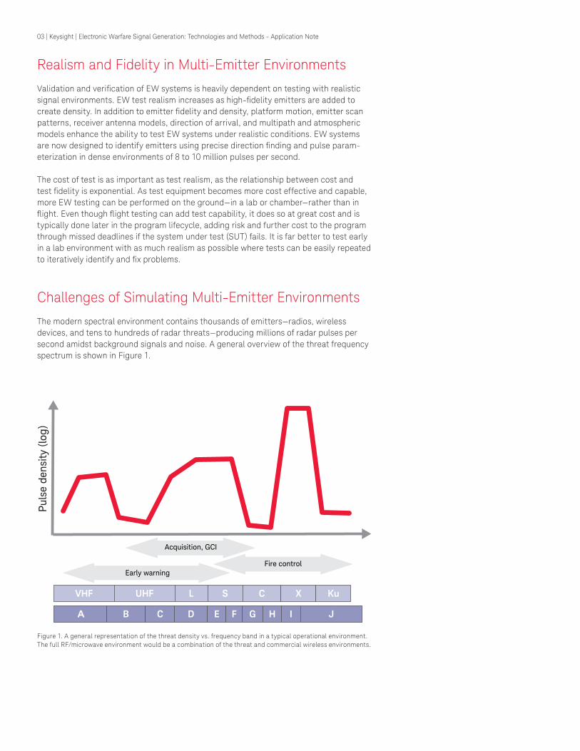
The modern spectral environment contains thousands of emitters—radios, wireless devices, and tens to hundreds of radar threats—producing millions of radar pulses per second amidst background signals and noise. A general overview of the threat frequency spectrum is shown in Figure 1.
Figure 1. A general representation of the threat density vs. frequency band in a typical operational environment. The full RF/microwave environment would be a combination of the threat and commercial wireless environments.
Fire control
Pu
lse d
en
sity
(lo
g)
VHF UHF L S C X Ku
B C D E F G H I JA
Early warning
Acquisition, GCI
04 | Keysight | Electronic Warfare Signal Generation: Technologies and Methods - Application Note
Simulating this environment is a major challenge, especially in the design phase, when design lexibility and productivity are at their greatest. The situation is very different from the typical wireless design task, where a single signal generator can produce the required signal, perhaps augmented by a second signal generator to add interference or noise.
In EW design the multiplicity and density of the environment—and often the bandwidth—make it impractical to use a single source or a small number of sources to simulate a single emitter or a small number of emitters. Cost, space, and complexity considerations rule out these approaches.
The only practical solution is to simulate many emitters with a single source, and to employ multiple sources—each typically simulating many emitters—when required to produce the needed signal density or to simulate speciic phenomena such as angle-of-arrival (AoA).
The ability to simulate multiple emitters at multiple frequencies depends on the pulse repetition frequency, duty cycle and number of emitters, and ability of the source to switch between frequency, amplitude, and modulation quickly.
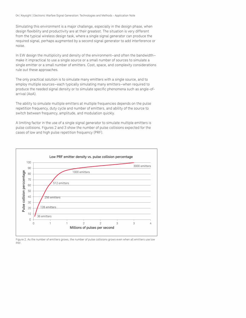
A limiting factor in the use of a single signal generator to simulate multiple emitters is pulse collisions. Figures 2 and 3 show the number of pulse collisions expected for the cases of low and high pulse repetition frequency (PRF).
Figure 2. As the number of emitters grows, the number of pulse collisions grows even when all emitters use low PRF.
36 emitters
128 emitters
256 emitters
512 emitters
1000 emitters
3000 emitters
0
10
20
30
40
50
60
70
80
90
100
0 1 1 2 2 3 3 4
Pu
lse c
ollis
ion
perc
cen
tag
e
Millions of pulses per second
Low PRF emitter density vs. pulse collision percentage
05 | Keysight | Electronic Warfare Signal Generation: Technologies and Methods - Application Note
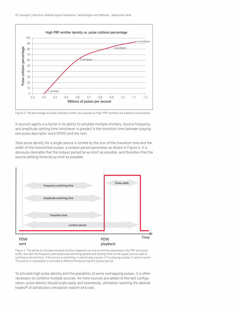
Figure 3. The percentage of pulse collisions climbs very quickly as high-PRF emitters are added to a simulation.
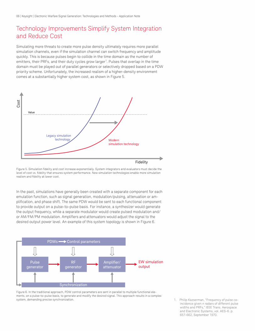
Figure 4. The ability to simulate multiple emitters depends not only on emitter parameters like PRF and pulse width, but also the frequency and amplitude switching speeds and setting times of the signal source used to synthesize the emitters. If the source is switching, it cannot play a pulse. If it is playing a pulse, it cannot switch. The source is unavailable to simulate a different threat during the lockout period.
1 emitter
2 emitters
3 emitters
4 emitters
0
10
20
30
40
50
60
70
80
90
100
0.2 0.3 0.4 0.5 0.6 0.7 0.8 0.9 1.0 1.1 1.2
Pu
lse c
ollis
ion
perc
en
tag
e
Millions of pulses per second
High PRF emitter density vs. pulse collision percentage
A source’s agility is a factor in its ability to simulate multiple emitters. Source frequency and amplitude settling time (whichever is greater) is the transition time between playing one pulse descriptor word (PDW) and the next.
Total pulse density for a single source is limited by the sum of the transition time and the width of the transmitted pulses, a lockout period parameter as shown in Figure 4. It is obviously desirable that the lockout period be as short as possible, and therefore that the source settling times be as brief as possible.
To simulate high pulse density and the possibility of some overlapping pulses, it is often necessary to combine multiple sources. As more sources are added to the test conigu-ration, pulse density should scale easily and seamlessly, ultimately reaching the desired tradeoff of satisfactory simulation realism and cost.
TimePDWsent
PDWplayback
Pulse width
Lockout period
Transition time
Amplitude switching time
Frequency switching time
06 | Keysight | Electronic Warfare Signal Generation: Technologies and Methods - Application Note
Technology Improvements Simplify System Integration and Reduce Cost
Simulating more threats to create more pulse density ultimately requires more parallel simulation channels, even if the simulation channel can switch frequency and amplitude quickly. This is because pulses begin to collide in the time domain as the number of emitters, their PRFs, and their duty cycles grow larger1. Pulses that overlap in the time domain must be played out of parallel generators or selectively dropped based on a PDW priority scheme. Unfortunately, the increased realism of a higher-density environment comes at a substantially higher system cost, as shown in Figure 5.
1. Philip Kazserman, “Frequency of pulse co-incidence given n radars of different pulse widths and PRFs,” IEEE Trans. Aerospace and Electronic Systems, vol. AES-6. p. 657-662, September 1970.
Figure 5. Simulation idelity and cost increase exponentially. System integrators and evaluators must decide the level of cost vs. idelity that ensures system performance. New simulation technologies enable more simulation realism and idelity at lower cost.
Figure 6. In the traditional approach, PDW control parameters are sent in parallel to multiple functional ele-ments, on a pulse-to-pulse basis, to generate and modify the desired signal. This approach results in a complex system, demanding precise synchronization.
In the past, simulations have generally been created with a separate component for each emulation function, such as signal generation, modulation/pulsing, attenuation or am-pliication, and phase shift. The same PDW would be sent to each functional component to provide output on a pulse-to-pulse basis. For instance, a synthesizer would generate the output frequency, while a separate modulator would create pulsed modulation and/or AM/FM/PM modulation. Ampliiers and attenuators would adjust the signal to the desired output power level. An example of this system topology is shown in Figure 6.
Fidelity
Legacy simulationtechnology Modern
simulation technology
Co
st
Value
Pulsegenerator
RFgenerator
Amplifier/attenuator
EW simulationoutput
Synchronization
PDWs Control parameters
07 | Keysight | Electronic Warfare Signal Generation: Technologies and Methods - Application Note
1. Reproduced by permission from David Ad-amy, EW 101: A First Course in Electronic Warfare, Norwood, MA: Artech House, Inc., 2001. © 2001 by Artech House, Inc.
Figure 7. A signal generation approach using separate functional elements can be scaled up in a straightforward manner to increase pulse density and generate a more realistic environment. Unfortunately cost and space requirements scale up rapidly as well.1
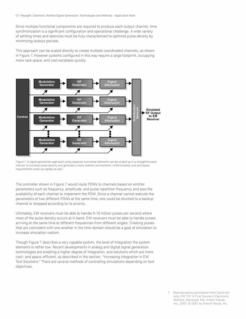
Since multiple functional components are required to produce each output channel, time synchronization is a signiicant coniguration and operational challenge. A wide variety of settling times and latencies must be fully characterized to optimize pulse density by minimizing lockout periods.
This approach can be scaled directly to create multiple coordinated channels, as shown in Figure 7. However systems conigured in this way require a large footprint, occupying more rack space, and cost escalates quickly.
The controller shown in Figure 7 would route PDWs to channels based on emitter parameters such as frequency, amplitude, and pulse repetition frequency and also the availability of each channel to implement the PDW. Since a channel cannot execute the parameters of two different PDWs at the same time, one could be shunted to a backup channel or dropped according to its priority.
Ultimately, EW receivers must be able to handle 8-10 million pulses per second where most of the pulse density occurs at X-band. EW receivers must be able to handle pulses arriving at the same time at different frequencies from different angles. Creating pulses that are coincident with one another in the time domain should be a goal of simulation to increase simulation realism.
Though Figure 7 describes a very capable system, the level of integration the system elements is rather low. Recent developments in analog and digital signal generation technologies are enabling a higher degree of integration, and solutions which are more cost- and space-eficient, as described in the section, “Increasing Integration in EW Test Solutions.” There are several methods of controlling simulations depending on test objectives.

08 | Keysight | Electronic Warfare Signal Generation: Technologies and Methods - Application Note
Control of Hardware-in-the-Loop Testing
Depending on the integration of simulation elements and the simulation length, sce-narios can be played from list memory or streamed over a digital interface such as low-voltage differential signaling (LVDS). List mode plays PDWs from list memory for shorter scenario lengths with some ability to trigger between lists for an adaptive (closed-loop) simulation in response to the SUT.
For example, there is often a need to switch between one simulated threat mode to another in response to identiication and jamming by the SUT. For long scenario lengths with fast control over scenario changes, PDWs can be streamed over the LVDS to the signal generation system operating in an agile controller mode. In this case, simulation software generates batches of PDWs according to simulation kinematic granularity and streams them ahead of their desired play time.
In either method of control, the goals are to stress the SUT with increasing pulse density, depending on the number of simulation channels available and the parameters of the threats to be simulated. As pulse density increases, PDWs can be dropped according to a priority scheme as they increasingly collide in the time domain and there are insufi-cient signal generation channels to play them.
Creating AoA
In addition to creating emitters with the desired idelity and density, it is also important to match the geometry and kinematics of EW scenarios since the AoA of a radar threat to the EW system changes slowly compared to other parameters such as center frequency and pulse repetition frequency.
EW systems measure AoA and estimate distance using amplitude comparison, differen-tial Doppler, interferometry (phase difference), and time difference of arrival (TDoA). Pre-cise AoA measurements enable precise localization of radar threats. New stand-off jam-ming systems use active electronically-scanned arrays capable of precise beam forming to minimize loss of jamming power due to beam spreading towards a threat. Moreoever, EW receivers with better AoA capability reduce the need for pulse de-interleaving and sorting. Consequently, AoA is an increasingly-important test requirement.
Techniques for creating AoAIn the past, AoA was created with a combination of signal sources and analog phase shifters, attenuators, and gain blocks in the cable path to the SUT. Analog elements in the cable path took up a lot of space, had limited resolution, and were expensive. As an alternative, and depending on their architecture, sources can be linked together to create phase coherent output, allowing for iner control over creating phase fronts to the SUT. Similarly, amplitude control at the source can be used to create appropriate amplitude differences at SUT receive channels.
The ability to control AoA to meet modern test requirements depends on the architec-ture of the source. At a minimum, it should be possible to lock the local oscillators (LOs) of multiple sources together so that they all share the same phase. Often, calibration is required to inely align phase and timing between sources.
Creating small, accurate, and repeatable differences in phase or frequency between channels is the next challenge. Sources based on DDS architecture allow AoA to be con-trolled digitally in a numerically-controlled oscillator. Phase alignment in a DDS source is then a matter of sharing reference clocks. Calibrations to provide accuracy and repeat-ability can be uploaded to a table to be applied in real-time.
09 | Keysight | Electronic Warfare Signal Generation: Technologies and Methods - Application Note
Overview of Source Technologies for EW Test
The characteristics and tradeoffs of EW signal generation systems are largely deter-mined by the core synthesizer and oscillator technologies used. To provide insight into the most signiicant choices for EW engineers, this section will summarize the three principal technologies currently available:
– Direct analog synthesis (DAS) – Phase-locked loop or indirect analog synthesis (PLL, frequently fractional-N) – Direct digital synthesis (DDS)
General source requirementsSignal sources used to test EW systems must be broadband. Traditionally, a frequency range of 0.5 to 18 GHz was required. Frequency requirements have expanded dramati-cally in recent years, now beginning near DC and extending as high as 40 GHz. This allows systems to simulate early warning, ire control, and missile-seeker radars from a single output channel.
In addition to wide frequency coverage, sources for EW test must have fast frequency and amplitude switching speeds to simulate different radars operating in different modes in different frequency bands.
PLLs and fractional-N synthesis
Indirect synthesis
Most general-purpose sources today are PLL-based, where a broadband oscillator such as a voltage- controlled or YIG-tuned oscillator is locked to a stable reference in a phase-locked loop (PLL). The PLL improves signal quality by reducing phase noise and spurious signals in the output. To provide a combination of wide frequency range and ine frequency resolution, PLL-based sources have been conigured with a com-bination of sum and step loops or a single loop with ine fractional division capability. These fractional-N PLLs offer excellent signal quality and ine frequency resolution in a cost-effective single-loop coniguration, making them a good choice for general purpose signal sources.
Unfortunately, the required control loop iltering in PLLs results in a signiicant settling or loop-response time. This limits the ability of the synthesizer to switch frequency quickly. Due to their comparatively large transition time, these sources are limited in their ability to simulate multiple radar threats out of a single channel, even if they have the necessary broadband frequency coverage and frequency resolution. They also lack phase-repeat-able switching capability.
10 | Keysight | Electronic Warfare Signal Generation: Technologies and Methods - Application Note
Direct analog synthesis
A direct analog synthesizer typically contains several stable frequency references mul-tiplied or divided from the same crystal oscillator reference. These frequency references (and their harmonics) can be switched in and out of the signal path and multiplied, divid-ed, added, and subtracted to provide ine frequency resolution quickly. The frequencies of these references are chosen to reduce the amount of multiplication stages required such that phase noise increases only moderately as frequency is increased. Division to lower frequencies reduces the phase noise.
Since the switches and arithmetic operators used in the DAS approach operate very quickly and do not need loop iltering, these synthesizers have very high frequency agil-ity. They have therefore been a common architecture for EW test solutions.
However, DAS technology has several drawbacks. First, numerous stages are required to achieve the desired frequency resolution. Switching parallel and series multiplication, division, and mixing stages requires more hardware than PLLs and generally reduces re-liability. Second, circuit noise from each stage is cascaded, and phase noise is multiplied through the stages. Finally, each stage adds components which increase size, weight, and cost.
On the positive side for EW applications, DAS has the potential for limited phase-repeat-able frequency switching. However, though all frequencies are usually derived from the same reference, divider ambiguities generally preclude full phase-coherent switching.
DDS now suitable for EW applicationsThe DDS approach, based on DAC circuits, is a natural it for the needs of EW signal simulation. However, until recently, DACs were not available with the required combina-tion of fast sample rates and high purity.
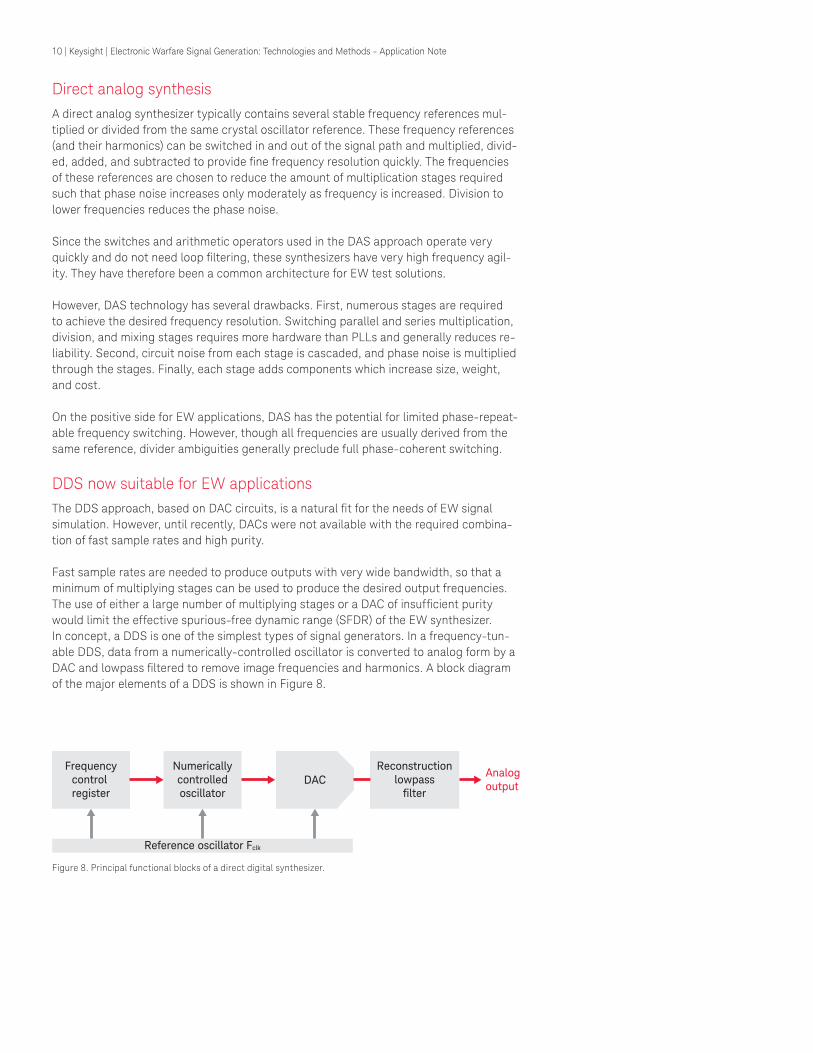
Fast sample rates are needed to produce outputs with very wide bandwidth, so that a minimum of multiplying stages can be used to produce the desired output frequencies. The use of either a large number of multiplying stages or a DAC of insuficient purity would limit the effective spurious-free dynamic range (SFDR) of the EW synthesizer.In concept, a DDS is one of the simplest types of signal generators. In a frequency-tun-able DDS, data from a numerically-controlled oscillator is converted to analog form by a DAC and lowpass iltered to remove image frequencies and harmonics. A block diagram of the major elements of a DDS is shown in Figure 8.
Figure 8. Principal functional blocks of a direct digital synthesizer.
Frequencycontrol register
Numericallycontrolledoscillator
DACReconstruction
lowpassfilter
Reference oscillator Fclk
Analogoutput
11 | Keysight | Electronic Warfare Signal Generation: Technologies and Methods - Application Note
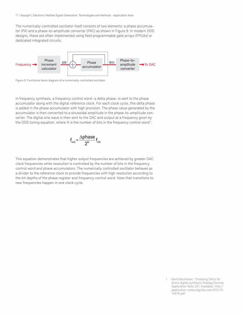
Figure 9. Functional block diagram of a numerically-controlled oscillator.
The numerically-controlled oscillator itself consists of two elements: a phase accumula-tor (PA) and a phase-to-amplitude converter (PAC) as shown in Figure 9. In modern DDS designs, these are often implemented using ield programmable gate arrays (FPGAs) or dedicated integrated circuits.
In frequency synthesis, a frequency control word—a delta phase—is sent to the phase accumulator along with the digital reference clock. For each clock cycle, this delta phase is added in the phase accumulator with high precision. The phase value generated by the accumulator is then converted to a sinusoidal amplitude in the phase-to-amplitude con-verter. The digital sine wave is then sent to the DAC and output at a frequency given by the DDS tuning equation, where N is the number of bits in the frequency control word1:
This equation demonstrates that higher output frequencies are achieved by greater DAC clock frequencies while resolution is controlled by the number of bits in the frequency control word and phase accumulators. The numerically controlled oscillator behaves as a divider to the reference clock to provide frequencies with high resolution according to the bit depths of the phase register and frequency control word. Note that transitions to new frequencies happen in one clock cycle.
1. David Buchanan, “Choosing DACs for direct digital synthesis,”Analog Devices Application Note 237, Available:(http://application-notes.digchip.com/013/13-14876.pdf)
Phaseaccumulator
Phase-to-amplitudeconverter
To DACPhase
incrementcalculator
∆Φ Φ(t)Frequency
∆out clkN
phasef = f
2
12 | Keysight | Electronic Warfare Signal Generation: Technologies and Methods - Application Note
Advantages of DDS
The new Keysight UXG agile signal generator uses DDS technology made possible by a Keysight-proprietary DAC to generate multi-emitter simulations. DDS has several advan-tages over other synthesis technologies for EW applications:
– Digital control of extremely ine frequency and phase tuning increments within a single clock cycle. In the Keysight UXG, frequency resolution is one Hertz and phase resolution is sub-degree. Fractional-N techniques can provide micro-Hertz resolu-tion, but frequency changes are much slower due to PLL iltering. DAS techniques provide rapid frequency switching, but at a cost in frequency resolution.
– Fast frequency hopping with phase continuity and phase repeatability to simu-late multiple pulse-Doppler radars at different frequencies while maintaining their original phase. This combination of phase control and hopping speed is unique to the Keysight UXG. DAS techniques offer hop speed and frequency/phase repeatability only under limited conditions.
– Modulation is created in the digital domain, providing numerical precision and re-peatability.
There are other advantages to using DDS that are of interest to the EW engineer. Many DDSs employ a digital modulator for amplitude, frequency, and phase modulation for creation of digitally-modulated signals in the numerically-controlled oscillator. Linear frequency modulated (LFM) chirps and Barker codes can also be directly synthesized using the numerically-controlled oscillator. Chirp bandwidth depends on the bandwidth of the bandpass ilters after each multiplication stage and whether the signal is crossing a band.
Microwave source architecture using DDSModern EW applications require frequency coverage to 40 GHz, along with high agility and high purity. Digital signal processing technologies for numeric signal creation have been adequate for some time, but wideband DAC performance has been inadequate for these applications. Available DACs with very wide bandwidth and high clock rate have not been suficiently pure, while DACs with good signal purity and high bit depth have been limited to lower frequency clocks and narrower bandwidth.
Recent DAC innovations from Keysight provide an example of a DAC and DDS suitable for EW test applications. The DAC has been designed for RF applications, with a com-bination of high bit depth and excellent purity, including spurious-free dynamic range and phase noise. The high sample rate of the DAC supports a wide bandwidth DDS that allows microwave frequencies to be synthesized with a low number of multiplication stages. Limiting multiplication stages limits the phase noise and spurious signals present in microwave output.
EW testing also requires precise signal amplitudes, over a wide range of power levels. These power levels must be switched as fast as frequencies are changed, without signal distortion from attenuator settling. As with the DAC, these demands have led Keysight to develop a new series of FET switches to implement a solid-state attenuator with high agility, low distortion, and an amplitude range of 120 dB. The agile amplitude range of the attenuator is 80 dB anywhere in the 0 dBm to -120 dBm output range.
The architecture of a true DDS based, agile microwave signal generator utilizing develop-ments in DAC and FET switching technology is shown in Figure 10.
13 | Keysight | Electronic Warfare Signal Generation: Technologies and Methods - Application Note
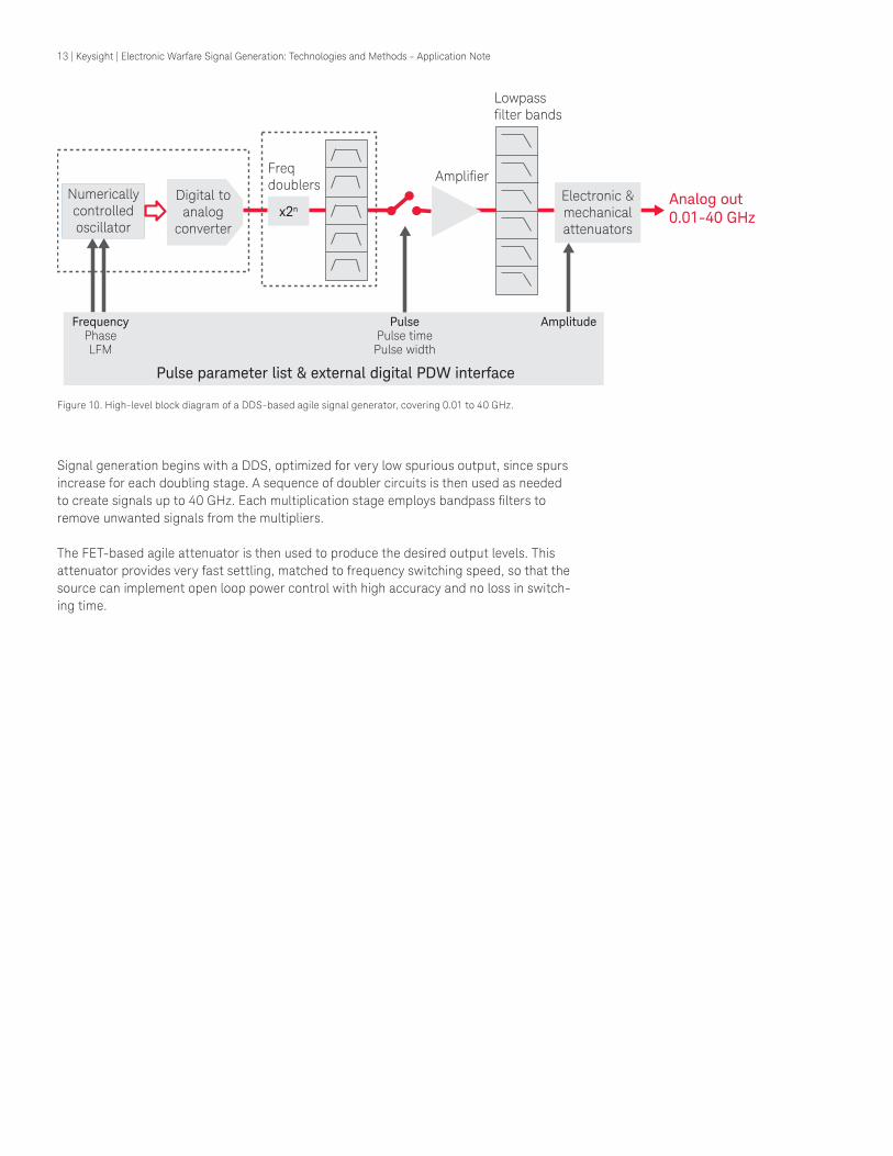
Figure 10. High-level block diagram of a DDS-based agile signal generator, covering 0.01 to 40 GHz.
Signal generation begins with a DDS, optimized for very low spurious output, since spurs increase for each doubling stage. A sequence of doubler circuits is then used as needed to create signals up to 40 GHz. Each multiplication stage employs bandpass ilters to remove unwanted signals from the multipliers.
The FET-based agile attenuator is then used to produce the desired output levels. This attenuator provides very fast settling, matched to frequency switching speed, so that the source can implement open loop power control with high accuracy and no loss in switch-ing time.
Numericallycontrolledoscillator
Electronic &mechanicalattenuators
Analog out0.01-40 GHzx2n
Freqdoublers
Lowpassfilter bands
Amplifier
Pulse parameter list & external digital PDW interface
FrequencyPhaseLFM
PulsePulse timePulse width
Amplitude
Digital toanalog
converter
14 | Keysight | Electronic Warfare Signal Generation: Technologies and Methods - Application Note
Increasing Integration in EW Test Solutions
A general trend in EW simulation solutions is to absorb more simulation elements into the RF/microwave signal source. For example, the Keysight UXG agile signal generator combines the intra-pulse modulation, pulse modulation, and ampliication/attenuation stages into the fast frequency synthesizer.
By implementing a high level of functional integration, a DDS-based agile source, and a matching agile attenuator, the UXG can meet important functional and performance requirements for EW test:
– Fast frequency, amplitude, and phase switching for fast transitions between multiple emitters
– High dynamic range to match the dynamic range of the modern EW receiver – A wide, accurate, agile amplitude range to simulate multiple threats with accurate
power levels and switch amplitude as quickly as frequency – Low noise loor to test receiver sensitivity as channels are combined – Pulse modulation with a high on/off ratio and fast settling with low distortion – Intrapulse modulation capability for pulse compression such as Barker codes and
linear frequency modulation – Scalable to multi-channel and multi-port threat simulation to increase pulse density
and realism easily – Wide frequency range from near DC to 40 GHz to keep pace with modern threat
simulation requirements – BCD frequency control interface for backward compatibility with legacy sources
previously used as LOs – LVDS interface to allow high-rate PDW streaming—EW simulation sources need a
fast, full-featured interface for streaming complete PDWs at a high rate rather than frequency-only control
In systems with a traditional, distributed architecture (as described in Figure 7) the synchronization of an agile LO with functions such as pulse modulation, frequency/phase modulation, and amplitude control is a considerable challenge. In an integrated EW test solution such as the UXG, this synchronization is automatic, provided by the test equip-ment itself. By simplifying hardware and system complexity, this integrated approach promises to improve both performance and reliability.
15 | Keysight | Electronic Warfare Signal Generation: Technologies and Methods - Application Note
Conclusion
A variety of technologies have been used to generate the signals needed for effective EW
simulation. Each of these technologies has brought a different combination of beneits and challenges. The highest idelity solutions have provided very realistic simulations of the EW environment but their use has been limited by their complexity and expense.
Recent innovations in core hardware such as DACs and FPGAs have enabled new solu-tions with the hardware simplicity and reliability of traditional test equipment. These solutions will provide dramatic improvements in solution cost and size, bringing high-idelity EW environment simulation to a much earlier phase in the design process. Using realistic EW environment simulation at the optimization and pre-veriication stages of design will improve performance, speed the design process, and reduce overall costs.
16 | Keysight | Electronic Warfare Signal Generation: Technologies and Methods - Application Note
myKeysight
www.keysight.com/find/mykeysight
A personalized view into the information most relevant to you.
www.lxistandard.org
LAN eXtensions for Instruments puts the power of Ethernet and the Web inside your test systems. Keysight is a founding member of the LXI consortium.
Three-Year Warranty
www.keysight.com/find/ThreeYearWarranty
Keysight’s commitment to superior product quality and lower total cost of ownership. The only test and measurement company with three-year warranty standard on all instruments, worldwide.
Keysight Assurance Plans
www.keysight.com/find/AssurancePlans
Up to five years of protection and no budgetary surprises to ensure your instruments are operating to specification so you can rely on accurate measurements.
www.keysight.com/go/quality
Keysight Technologies, Inc.DEKRA Certified ISO 9001:2008 Quality Management System
Keysight Channel Partners
www.keysight.com/find/channelpartners
Get the best of both worlds: Keysight’s measurement expertise and product breadth, combined with channel partner convenience.
www.keysight.com/find/radarwww.keysight.com/find/uxg
This information is subject to change without notice.© Keysight Technologies, 2014Published in USA, September 16, 20145992-0094ENwww.keysight.com
For more information on Keysight Technologies’ products, applications or services, please contact your local Keysight office. The complete list is available at:www.keysight.com/find/contactus
Americas Canada (877) 894 4414Brazil 55 11 3351 7010Mexico 001 800 254 2440United States (800) 829 4444
Asia PaciicAustralia 1 800 629 485China 800 810 0189Hong Kong 800 938 693India 1 800 112 929Japan 0120 (421) 345Korea 080 769 0800Malaysia 1 800 888 848Singapore 1 800 375 8100Taiwan 0800 047 866Other AP Countries (65) 6375 8100
Europe & Middle East
Austria 0800 001122Belgium 0800 58580Finland 0800 523252France 0805 980333Germany 0800 6270999Ireland 1800 832700Israel 1 809 343051Italy 800 599100Luxembourg +32 800 58580Netherlands 0800 0233200Russia 8800 5009286Spain 0800 000154Sweden 0200 882255Switzerland 0800 805353
Opt. 1 (DE)Opt. 2 (FR)Opt. 3 (IT)
United Kingdom 0800 0260637
For other unlisted countries:www.keysight.com/find/contactus(BP-09-04-14)