Embed Size (px)
Citation preview
Programmer’s Reference Guide
Keysight N6705 DC Power Analyzer
2 N6705 Programmer’s Reference Guide
Legal Notices © Keysight Technologies 2006 - 2015
No part of this document may be photocopied, reproduced, or translated to another language without the prior agreement and written consent of Keysight Technologies as governed by United States and international copyright laws.
Warranty The material contained in this document is provided “as is,” and is subject to being changed, without notice, in future editions. Further, to the maximum extent permitted by applicable law, Keysight disclaims all warranties, either express or implied, with regard to this manual and any information contained herein, including but not limited to the implied warranties of merchantability and fitness for a particular purpose. Keysight shall not be liable for errors or for incidental or consequential damages in connection with the furnishing, use, or performance of this document or of any information contained herein. Should Keysight and the user have a separate written agreement with warranty terms covering the material in this document that conflict with these terms, the warranty terms in the separate agreement shall control.
Manual Editions Manual Part Number: N6705-90902 Edition 7, January 2015 Available in electronic format only.
Certification Keysight Technologies certifies that this product met its published specifications at time of shipment from the factory. Keysight Technologies further certifies that its calibration measurements are traceable to the United States National Institute of Standards and Technology, to the extent allowed by the Institute's calibration facility, and to the calibration facilities of other International Standards Organization members.
Exclusive Remedies THE REMEDIES PROVIDED HEREIN ARE THE CUSTOMER'S SOLE AND EXCLUSIVE REMEDIES. KEYSIGHT TECHNOLOGIES SHALL NOT BE LIABLE FOR ANY DIRECT, INDIRECT, SPECIAL, INCIDENTAL, OR CONSEQUENTIAL DAMAGES, WHETHER BASED ON CONTRACT, TORT, OR ANY OTHER LEGAL THEORY.
Assistance This product comes with the standard product warranty. Warranty options, extended support contacts, product maintenance agreements and customer assistance agreements are also available. Contact your nearest Keysight Technologies Sales and Service office for further information on Keysight Technologies' full line of Support Programs.
Technologies Licenses The hardware and or software described in this document are furnished under a license and may be used or copied only in accordance with the terms of such license.
U.S. Government Restricted Rights Software and technical data rights granted to the federal government include only those rights customarily provided to end user customers. Keysight provides this customary commercial license in Software and technical data pursuant to FAR 12.211 (Technical Data) and 12.212 (Computer Software) and, for the Department of Defense, DFARS 252.227-7015 (Technical Data – Commercial Items) and DFARS 227.7202-3 (Rights in Commercial Computer Software or Computer Software Documentation).
Trademarks Microsoft and Windows are U.S. registered trademarks of Microsoft Corporation.
N6705 Programmer’s Reference Guide 3
Contents
1 - Introduction .............................................................................................................. 5 Instrument Drivers and IO Libraries ................................................. 6 Instrument Web Server .................................................................... 6 Keysight N6705 Product Documentation ........................................ 7
2 - Introduction to the SCPI Language .......................................................................... 9 SCPI Commands ............................................................................. 10 SCPI Messages ............................................................................... 12 SCPI Conventions and Data Formats ............................................ 14 SCPI Command Completion .......................................................... 16
3 - Commands by Subsystem ...................................................................................... 17 ABORt Commands Introduction .................................................... 18 CALibrate Subsystem Introduction ................................................ 24 Common Commands Introduction ................................................ 44 DISPlay Commands Introduction ................................................... 64 FETCh Subsystem Introduction ..................................................... 66 FORMat Commands Introduction .................................................. 99 HCOPy Commands Introduction.................................................. 102 INITiate Subsystem Introduction ................................................. 104 MEASure Subsystem Introduction ............................................... 111 MMEMory Subsystem Introduction ............................................. 135 OUTPut Subsystem Introduction ................................................. 143 SENSe Subsystem Introduction ................................................... 169 SOURce Subsystem Introduction ................................................ 217 STATus Subsystem Introduction .................................................. 479 SYSTem Commands Introduction ................................................ 503 TRIGger Subsystem Introduction ................................................. 521
4 - Command Quick Reference .................................................................................. 549 SCPI Command Summary ........................................................... 550 Non-Volatile Settings ................................................................... 559 Reset Settings (*RST) ................................................................... 560 Keysight N678xA SMU Emulation Mode Settings ....................... 562
5 - Programming Examples ....................................................................................... 563 Arb Programming Example .......................................................... 564 Output Programming Example .................................................... 566 List Programming Example .......................................................... 568 Digitizer Programming Example .................................................. 570
6 - SCPI Error Messages ............................................................................................ 573 Introduction .................................................................................. 574 Error List ....................................................................................... 574

N6705 Programmer’s Reference Guide 5
1 Introduction Instrument Drivers and IO Libraries ................................................. 6 Instrument Web Server .................................................................... 6 Keysight N6705 Product Documentation ........................................ 7
This manual contains reference information to help you program the Keysight N6705 DC Power Analyzer over the remote interface using the SCPI programming language. The Keysight N6705 supports the SCPI programming language on all of its remote I/O interfaces. This information applies to the following mainframes:
N6705A, N6705B.
For additional information on the Keysight N6705, be sure to browse the Product Reference CD-ROM shipped with the instrument or go to http://www.keysight.com/find/N6705.
1 Introduction
6 N6705 Programmer’s Reference Guide
Instrument Drivers and IO Libraries
We have included the following drivers and libraries on the Product Reference CD-ROM shipped with your Keysight N6705.
IVI-COM Drivers
VXIplug&play Drivers
Keysight IO Libraries are included on a separate Automation-Ready CD-ROM, which is also shipped with your Keysight N6705.
You can also download the drivers and libraries from the Keysight web site at www.keysight.com/find/inst_drivers.
Instrument Web Server
The Keysight N6705 has a built-in Web server that lets you control them directly from an internet browser on your computer. With the Web server, you can access the front panel control functions including the LAN configuration parameters.
NOTE The built-in Web server only operates over the LAN interface. It requires Internet Explorer 6+ or Netscape 6.2+. You also need the Java (Sun) plug-in. This is included in the Java Runtime Environment. Refer to Sun Microsystem’s website http://www.sun.com.
The Web server is enabled when shipped. To launch the Web server:
1. Establish a LAN interface connection from your computer to the Keysight N6705.
2. To launch the Web server, enter the instrument’s IP address or fully-qualified hostname into the browser’s Address field.
3. To begin controlling your instrument, click on the Browser Web Control button in the navigation bar on the left.
4. For additional Help, click on the Help with this Page button.

Introduction 1
N6705 Programmer’s Reference Guide 7
Keysight N6705 Product Documentation
The following additional documents are available on the Keysight N6705 Product Reference CD-ROM, shipped with the Keysight N6705.
N6705 User’s Guide
N6700 Family Specifications Guide
N6705 Service Guide
NOTE You can contact Keysight Technologies at one of the following telephone numbers for warranty, service, or technical support information. In the United States: (800) 829-4444 In Europe: 31 20 547 2111 In Japan: 0120-421-345 Or use our Web link for information on contacting Keysight in your country or specific location: www.keysight.com/find/assist Or contact your Keysight Technologies Representative.
The web contains the most up to date version of the manuals. Go to www.keysight.com/find/N6705 to get the latest version of the manuals.

N6705 Programmer’s Reference Guide 9
2 Introduction to the SCPI Language SCPI Commands ............................................................................. 10 SCPI Messages ............................................................................... 12 SCPI Conventions and Data Formats ............................................ 14 SCPI Command Completion .......................................................... 16
This chapter contains a brief introduction to the SCPI Programming language.
SCPI (Standard Commands for Programmable Instruments) is a programming language for controlling test and measurement instruments. SCPI provides instrument control with a standardized command syntax and style, as well as a standardized data interchange format.
2 Introduction to the SCPI Language
10 N6705 Programmer’s Reference Guide
SCPI Commands
SCPI has two types of commands, common and subsystem.
Common commands are defined by the IEEE 488.2 standard to perform common interface functions such as reset, status, and synchronization. All common commands consist of a three-letter mnemonic preceded by an asterisk: *RST *IDN? *SRE 8.
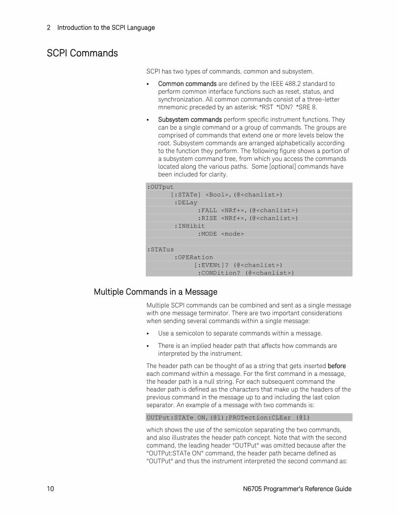
Subsystem commands perform specific instrument functions. They can be a single command or a group of commands. The groups are comprised of commands that extend one or more levels below the root. Subsystem commands are arranged alphabetically according to the function they perform. The following figure shows a portion of a subsystem command tree, from which you access the commands located along the various paths. Some [optional] commands have been included for clarity.
:OUTput [:STATe] <Bool>,(@<chanlist>) :DELay :FALL <NRf+>,(@<chanlist>) :RISE <NRf+>,(@<chanlist>) :INHibit :MODE <mode> :STATus :OPERation [:EVENt]? (@<chanlist>) :CONDition? (@<chanlist>)
Multiple Commands in a Message
Multiple SCPI commands can be combined and sent as a single message with one message terminator. There are two important considerations when sending several commands within a single message:
Use a semicolon to separate commands within a message.
There is an implied header path that affects how commands are interpreted by the instrument.
The header path can be thought of as a string that gets inserted before each command within a message. For the first command in a message, the header path is a null string. For each subsequent command the header path is defined as the characters that make up the headers of the previous command in the message up to and including the last colon separator. An example of a message with two commands is:
OUTPut:STATe ON,(@1);PROTection:CLEar (@1)
which shows the use of the semicolon separating the two commands, and also illustrates the header path concept. Note that with the second command, the leading header "OUTPut" was omitted because after the "OUTPut:STATe ON" command, the header path became defined as "OUTPut" and thus the instrument interpreted the second command as:
Introduction to the SCPI Language 2
N6705 Programmer’s Reference Guide 11
OUTPut:PROTection:CLEar (@1)
In fact, it would have been syntactically incorrect to include the "OUTPut" explicitly in the second command, since the result after combining it with the header path would be:
OUTPut:OUTPut:PROTection:CLEar (@1)
which is incorrect.
Moving Among Subsystems
In order to combine commands from different subsystems, you need to be able to reset the header path to a null string within a message. You do this by beginning the command with a colon (:), which discards any previous header path. For example, you could clear the output protection and check the status of the Operation Condition register in one message by using a root specifier as follows:
OUTPut:PROTection:CLEar (@1);:STATus:OPERation :CONDition? (@1)
The following message shows how to combine commands from different subsystems as well as within the same subsystem:
VOLTage:LEVel 7.5,(@1);PROTection 10,(@1);:CURRent :LEVel 0.5,(@1)
Note the use of the optional header LEVel to maintain the correct path within the subsystems, and the use of the root specifier to move between subsystems.
Including Common Commands
You can combine common commands with subsystem commands in the same message. Treat the common command as a message unit by separating it with a semicolon (the message unit separator). Common commands do not affect the header path; you may insert them anywhere in the message.
OUTPut OFF,(@1);*RCL 1;OUTPut ON,(@1)
Using Queries
Observe the following precautions with queries:
Add a blank space between the query indicator (?) and any subsequent parameter such as a channel list.
Allocate the proper number of variables for the returned data.
Read back all the results of a query before sending another command to the instrument. Otherwise, a Query Interrupted error will occur and the unreturned data will be lost.
2 Introduction to the SCPI Language
12 N6705 Programmer’s Reference Guide
Coupled Commands
When commands are coupled it means that the value sent by one command is affected by the settings of another command. The following commands are coupled:
[SOURce:]CURRent and [SOURce:]CURRent:RANGe.
[SOURce:]VOLTage and [SOURce:]VOLTage:RANGe.
If a range command is sent that places an output on a range with a lower maximum setting than the present level, an error is generated. This also occurs if a level is programmed with a value too large for the present range.
These types of errors can be avoided by sending the both level and range commands as a set, in the same SCPI message. For example,
CURRent 10,(@1);CURRent:RANGe 10,(@1)<NL>
will always be correct because the commands are not executed until the message terminator is received. Because the range and setting information is received as a set, no range/setting conflict occurs.
SCPI Messages
There are two types of SCPI messages, program and response.
A program message consists of one or more properly formatted SCPI commands sent from the controller to the instrument. The message, which may be sent at any time, requests the instrument to perform some action.
A response message consists of data in a specific SCPI format sent from the instrument to the controller. The instrument sends the message only in response to a query header.
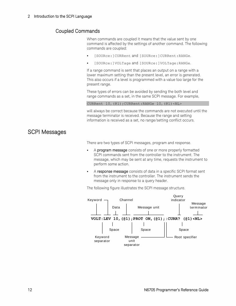
The following figure illustrates the SCPI message structure.
VOLT:LEV 10,(@1);PROT ON,(@1);:CURR? (@1)<NL>
Keyword
Keyword separator
Data
Channel
Message unitMessage
terminator
Message unit
separator
Root specifier
Query indicator
SpaceSpace Space
Introduction to the SCPI Language 2
N6705 Programmer’s Reference Guide 13
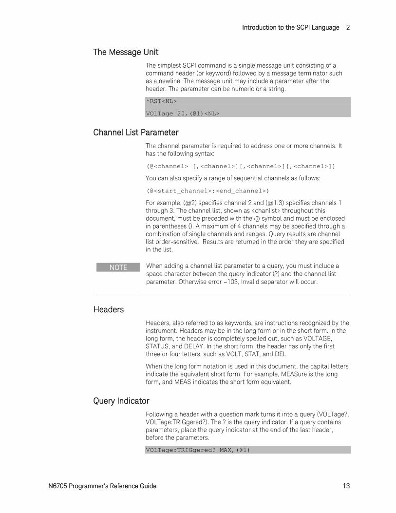
The Message Unit
The simplest SCPI command is a single message unit consisting of a command header (or keyword) followed by a message terminator such as a newline. The message unit may include a parameter after the header. The parameter can be numeric or a string.
*RST<NL>
VOLTage 20,(@1)<NL>
Channel List Parameter
The channel parameter is required to address one or more channels. It has the following syntax:
(@<channel> [,<channel>][,<channel>][,<channel>])
You can also specify a range of sequential channels as follows:
(@<start_channel>:<end_channel>)
For example, (@2) specifies channel 2 and (@1:3) specifies channels 1 through 3. The channel list, shown as <chanlist> throughout this document, must be preceded with the @ symbol and must be enclosed in parentheses (). A maximum of 4 channels may be specified through a combination of single channels and ranges. Query results are channel list order-sensitive. Results are returned in the order they are specified in the list.
NOTE When adding a channel list parameter to a query, you must include a space character between the query indicator (?) and the channel list parameter. Otherwise error –103, Invalid separator will occur.
Headers
Headers, also referred to as keywords, are instructions recognized by the instrument. Headers may be in the long form or in the short form. In the long form, the header is completely spelled out, such as VOLTAGE, STATUS, and DELAY. In the short form, the header has only the first three or four letters, such as VOLT, STAT, and DEL.
When the long form notation is used in this document, the capital letters indicate the equivalent short form. For example, MEASure is the long form, and MEAS indicates the short form equivalent.
Query Indicator
Following a header with a question mark turns it into a query (VOLTage?, VOLTage:TRIGgered?). The ? is the query indicator. If a query contains parameters, place the query indicator at the end of the last header, before the parameters.
VOLTage:TRIGgered? MAX,(@1)
2 Introduction to the SCPI Language
14 N6705 Programmer’s Reference Guide
Message Unit Separator
When two or more message units are combined into a compound message, separate the units with a semicolon.
STATus:OPERation? (@1);QUEStionable? (@1)
Root Specifier
When it precedes the first header of a message unit, the colon becomes the root specifier. It tells the command parser that this is the root or the top node of the command tree.
Message Terminator
A terminator informs SCPI that it has reached the end of a message. The following messages terminators are permitted:
newline <NL>, which is ASCII decimal 10 or hex 0A.
end or identify <END> (EOI with ATN false)
both of the above <NL><END>
also <CR><NL>
In the examples of this guide, there is an assumed message terminator at the end of each message.
SCPI Conventions and Data Formats
Conventions
The following SCPI conventions are used throughout this guide.
Angle brackets < >
Items within angle brackets are parameter abbreviations. For example, <NR1> indicates a specific form of numerical data.
Vertical bar | Vertical bars separate alternative parameters. For example, VOLT | CURR indicates that either "VOLT" or "CURR" can be used as a parameter.
Square brackets [ ] Items within square brackets are optional. The representation [SOURce:]VOLTage means that SOURce: may be omitted.
Parentheses ( ) Items within parentheses are used in place of the usual parameter types to specify a channel list. The notation (@1:3) specifies a channel list that includes channels 1, 2, and 3. The notation (@1,3) specifies a channel list that includes only channels 1 and 3.
Braces Braces indicate parameters that may be repeated zero or more times. It is used especially for showing arrays. The notation <A>,<B> shows that parameter "A" must be entered, while parameter "B" may be omitted or may be entered one or more times.
Introduction to the SCPI Language 2
N6705 Programmer’s Reference Guide 15
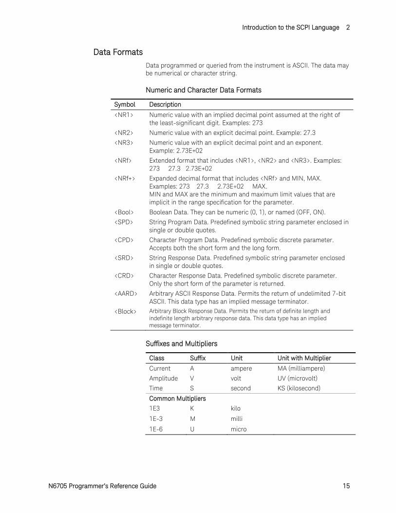
Data Formats
Data programmed or queried from the instrument is ASCII. The data may be numerical or character string.
Numeric and Character Data Formats
Symbol Description
<NR1> Numeric value with an implied decimal point assumed at the right of the least-significant digit. Examples: 273
<NR2> Numeric value with an explicit decimal point. Example: 27.3
<NR3> Numeric value with an explicit decimal point and an exponent. Example: 2.73E+02
<NRf> Extended format that includes <NR1>, <NR2> and <NR3>. Examples: 273 27.3 2.73E+02
<NRf+> Expanded decimal format that includes <NRf> and MIN, MAX. Examples: 273 27.3 2.73E+02 MAX. MIN and MAX are the minimum and maximum limit values that are implicit in the range specification for the parameter.
<Bool> Boolean Data. They can be numeric (0, 1), or named (OFF, ON).
<SPD> String Program Data. Predefined symbolic string parameter enclosed in single or double quotes.
<CPD> Character Program Data. Predefined symbolic discrete parameter. Accepts both the short form and the long form.
<SRD> String Response Data. Predefined symbolic string parameter enclosed in single or double quotes.
<CRD> Character Response Data. Predefined symbolic discrete parameter. Only the short form of the parameter is returned.
<AARD> Arbitrary ASCII Response Data. Permits the return of undelimited 7-bit ASCII. This data type has an implied message terminator.
<Block> Arbitrary Block Response Data. Permits the return of definite length and indefinite length arbitrary response data. This data type has an implied message terminator.
Suffixes and Multipliers
Class Suffix Unit Unit with Multiplier Current A ampere MA (milliampere) Amplitude V volt UV (microvolt) Time S second KS (kilosecond) Common Multipliers
1E3 K kilo 1E-3 M milli 1E-6 U micro
2 Introduction to the SCPI Language
16 N6705 Programmer’s Reference Guide
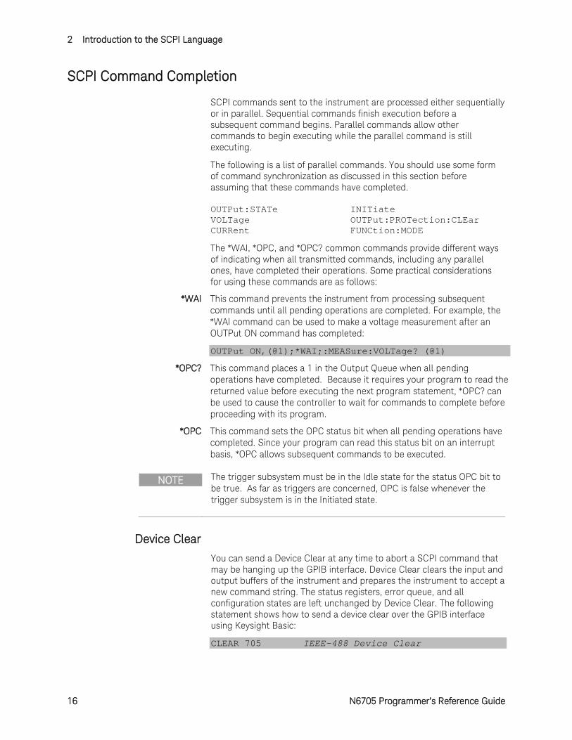
SCPI Command Completion
SCPI commands sent to the instrument are processed either sequentially or in parallel. Sequential commands finish execution before a subsequent command begins. Parallel commands allow other commands to begin executing while the parallel command is still executing.
The following is a list of parallel commands. You should use some form of command synchronization as discussed in this section before assuming that these commands have completed. OUTPut:STATe INITiate VOLTage OUTPut:PROTection:CLEar CURRent FUNCtion:MODE
The *WAI, *OPC, and *OPC? common commands provide different ways of indicating when all transmitted commands, including any parallel ones, have completed their operations. Some practical considerations for using these commands are as follows:
*WAI This command prevents the instrument from processing subsequent commands until all pending operations are completed. For example, the *WAI command can be used to make a voltage measurement after an OUTPut ON command has completed:
OUTPut ON,(@1);*WAI;:MEASure:VOLTage? (@1)
*OPC? This command places a 1 in the Output Queue when all pending operations have completed. Because it requires your program to read the returned value before executing the next program statement, *OPC? can be used to cause the controller to wait for commands to complete before proceeding with its program.
*OPC This command sets the OPC status bit when all pending operations have completed. Since your program can read this status bit on an interrupt basis, *OPC allows subsequent commands to be executed.
NOTE The trigger subsystem must be in the Idle state for the status OPC bit to be true. As far as triggers are concerned, OPC is false whenever the trigger subsystem is in the Initiated state.
Device Clear
You can send a Device Clear at any time to abort a SCPI command that may be hanging up the GPIB interface. Device Clear clears the input and output buffers of the instrument and prepares the instrument to accept a new command string. The status registers, error queue, and all configuration states are left unchanged by Device Clear. The following statement shows how to send a device clear over the GPIB interface using Keysight Basic:
CLEAR 705 IEEE-488 Device Clear
N6705 Programmer’s Reference Guide 17
3 Commands by Subsystem ABORt Commands Introduction .................................................... 18 CALibrate Subsystem Introduction ................................................ 24 Common Commands Introduction ................................................ 44 DISPlay Commands Introduction ................................................... 64 FETCh Subsystem Introduction ..................................................... 66 FORMat Commands Introduction .................................................. 99 HCOPy Commands Introduction.................................................. 102 INITiate Subsystem Introduction ................................................. 104 MEASure Subsystem Introduction ............................................... 111 MMEMory Subsystem Introduction ............................................. 135 OUTPut Subsystem Introduction ................................................. 143 SENSe Subsystem Introduction ................................................... 169 SOURce Subsystem Introduction ................................................ 217 STATus Subsystem Introduction .................................................. 479 SYSTem Commands Introduction ................................................ 503 TRIGger Subsystem Introduction ................................................. 521
This section gives the syntax and parameters for all the IEEE 488.2 SCPI commands and the Common commands used by the instrument. It is assumed that you are familiar with the material in chapter 2, which explains the terms, symbols, and syntactical structures used here and gives an introduction to programming. You should also be familiar with chapter 4 in the User’s Guide, in order to understand how the instrument functions.
Subsystem commands are specific to instrument functions. They can be a single command or a group of commands. The groups are comprised of commands that extend one or more levels below the root. The subsystem commands are arranged alphabetically according to the function they perform.
Common commands are defined by the IEEE 488.2 standard to perform common interface functions. They begin with an * and consist of three letters (command) or three letters and a ? (query). Common commands are grouped along with the subsystem commands according to the function they perform.
3 Commands by Subsystem
18 N6705 Programmer’s Reference Guide
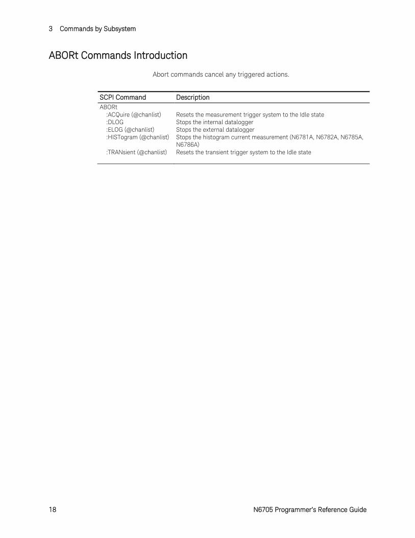
ABORt Commands Introduction
Abort commands cancel any triggered actions.
SCPI Command Description ABORt :ACQuire (@chanlist) Resets the measurement trigger system to the Idle state :DLOG Stops the internal datalogger :ELOG (@chanlist) Stops the external datalogger :HISTogram (@chanlist) Stops the histogram current measurement (N6781A, N6782A, N6785A,
N6786A) :TRANsient (@chanlist) Resets the transient trigger system to the Idle state
Commands by Subsystem 3
N6705 Programmer’s Reference Guide 19
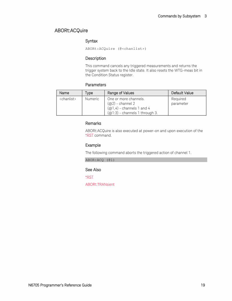
ABORt:ACQuire
Syntax
ABORt:ACQuire (@<chanlist>)
Description
This command cancels any triggered measurements and returns the trigger system back to the Idle state. It also resets the WTG-meas bit in the Condition Status register.
Parameters
Name Type Range of Values Default Value <chanlist> Numeric One or more channels.
(@2) - channel 2 (@1,4) - channels 1 and 4 (@1:3) - channels 1 through 3.
Required parameter
Remarks
ABORt:ACQuire is also executed at power-on and upon execution of the *RST command.
Example
The following command aborts the triggered action of channel 1.
ABOR:ACQ (@1)
See Also
*RST
ABORt:TRANsient
3 Commands by Subsystem
20 N6705 Programmer’s Reference Guide
ABORt:DLOG
Syntax
ABORt:DLOG
Description
This command stops the currently running data log and returns the trigger system back to the Idle state.
Example
The following command stops the currently running data log.
ABOR:DLOG
Commands by Subsystem 3
N6705 Programmer’s Reference Guide 21
ABORt:ELOG
Syntax
ABORt:ELOG (@<chanlist>)
Description
This command stops the external data log and returns the trigger system back to the Idle state.
Parameters
Name Type Range of Values Default Value <chanlist> Numeric One or more channels.
(@2) - channel 2 (@1,4) - channels 1 and 4 (@1:3) - channels 1 through 3.
Required parameter
Example
The following command stops the external data log on channel 1.
ABOR:ELOG (@1)
3 Commands by Subsystem
22 N6705 Programmer’s Reference Guide
ABORt:HISTogram
Syntax
ABORt:HISTogram (@<chanlist>)
Description
This command stops the histogram current measurement and returns the trigger system back to the Idle state.
NOTE This command only applies to models N6781A, N6782A, N6785A, and N6786A that have the Data Logger function installed.
Parameters
Name Type Range of Values Default Value <chanlist> Numeric One or more channels.
(@2) - channel 2 (@1,4) - channels 1 and 4 (@1:3) - channels 1 through 3.
Required parameter
Example
The following command stops the histogram measurement on channel 1.
ABOR:HIST (@1)
Commands by Subsystem 3
N6705 Programmer’s Reference Guide 23
ABORt:TRANsient
Syntax
ABORt:TRANsient (@<chanlist>)
Description
This command cancels any triggered actions and returns the trigger system back to the Idle state. ABORt:TRANsient also resets the WTG-tran bit in the Operation Condition Status register.
Parameters
Name Type Range of Values Default Value <chanlist> Numeric One or more channels.
(@2) - channel 2 (@1,4) - channels 1 and 4 (@1:3) - channels 1 through 3.
Required parameter
Remarks
If INITiate:CONTinuous:TRANsient ON has been programmed, ABORt does not turn off continuous triggers.
ABORt:TRANsient is also executed at power-on and upon execution of the *RST command.
Example
The following command aborts the triggered action of channel 1.
ABOR:TRAN (@1)
See Also
*RST
ABORt:ACQuire
INITiate:CONtinuous:TRANsient
3 Commands by Subsystem
24 N6705 Programmer’s Reference Guide
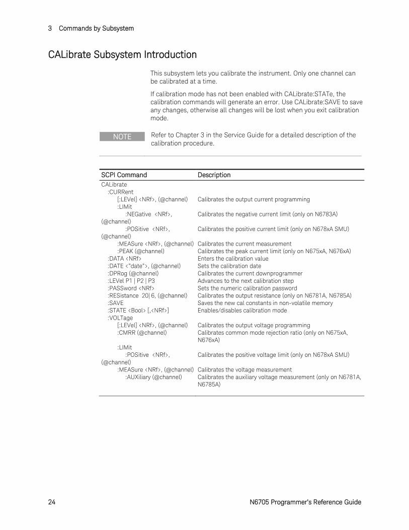
CALibrate Subsystem Introduction
This subsystem lets you calibrate the instrument. Only one channel can be calibrated at a time.
If calibration mode has not been enabled with CALibrate:STATe, the calibration commands will generate an error. Use CALibrate:SAVE to save any changes, otherwise all changes will be lost when you exit calibration mode.
NOTE Refer to Chapter 3 in the Service Guide for a detailed description of the calibration procedure.
SCPI Command Description CALibrate :CURRent [:LEVel] <NRf>, (@channel) Calibrates the output current programming :LIMit :NEGative <NRf>, (@channel)
Calibrates the negative current limit (only on N6783A)
:POSitive <NRf>, (@channel)
Calibrates the positive current limit (only on N678xA SMU)
:MEASure <NRf>, (@channel) Calibrates the current measurement :PEAK (@channel) Calibrates the peak current limit (only on N675xA, N676xA) :DATA <NRf> Enters the calibration value :DATE <”date”>, (@channel) Sets the calibration date :DPRog (@channel) Calibrates the current downprogrammer :LEVel P1 | P2 | P3 Advances to the next calibration step :PASSword <NRf> Sets the numeric calibration password :RESistance 20| 6, (@channel) Calibrates the output resistance (only on N6781A, N6785A) :SAVE Saves the new cal constants in non-volatile memory :STATE <Bool> [,<NRf>] Enables/disables calibration mode :VOLTage [:LEVel] <NRf>, (@channel) Calibrates the output voltage programming :CMRR (@channel) Calibrates common mode rejection ratio (only on N675xA,
N676xA) :LIMit :POSitive <NRf>, (@channel)
Calibrates the positive voltage limit (only on N678xA SMU)
:MEASure <NRf>, (@channel) Calibrates the voltage measurement :AUXiliary (@channel) Calibrates the auxiliary voltage measurement (only on N6781A,
N6785A)
Commands by Subsystem 3
N6705 Programmer’s Reference Guide 25
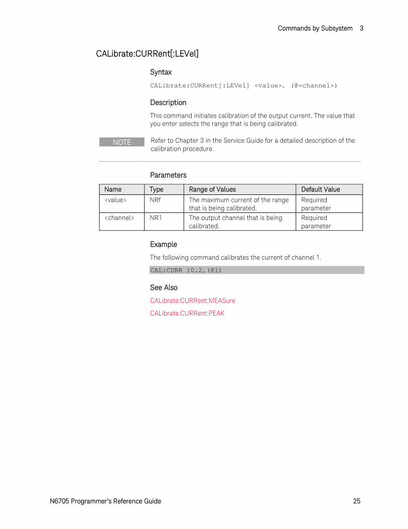
CALibrate:CURRent[:LEVel]
Syntax
CALibrate:CURRent[:LEVel] <value>, (@<channel>)
Description
This command initiates calibration of the output current. The value that you enter selects the range that is being calibrated.
NOTE Refer to Chapter 3 in the Service Guide for a detailed description of the calibration procedure.
Parameters
Name Type Range of Values Default Value <value> NRf The maximum current of the range
that is being calibrated. Required parameter
<channel> NR1 The output channel that is being calibrated.
Required parameter
Example
The following command calibrates the current of channel 1.
CAL:CURR 10.2,(@1)
See Also
CALibrate:CURRent:MEASure
CALibrate:CURRent:PEAK
3 Commands by Subsystem
26 N6705 Programmer’s Reference Guide
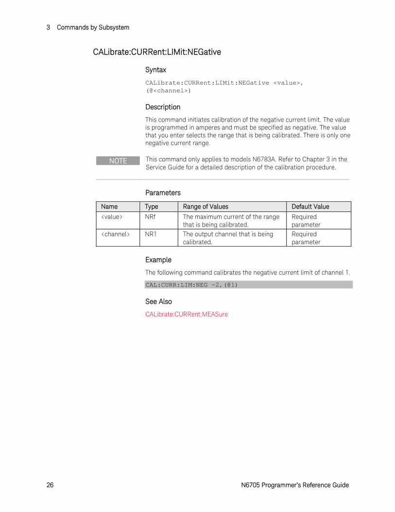
CALibrate:CURRent:LIMit:NEGative
Syntax
CALibrate:CURRent:LIMit:NEGative <value>, (@<channel>)
Description
This command initiates calibration of the negative current limit. The value is programmed in amperes and must be specified as negative. The value that you enter selects the range that is being calibrated. There is only one negative current range.
NOTE This command only applies to models N6783A. Refer to Chapter 3 in the Service Guide for a detailed description of the calibration procedure.
Parameters
Name Type Range of Values Default Value <value> NRf The maximum current of the range
that is being calibrated. Required parameter
<channel> NR1 The output channel that is being calibrated.
Required parameter
Example
The following command calibrates the negative current limit of channel 1.
CAL:CURR:LIM:NEG -2,(@1)
See Also
CALibrate:CURRent:MEASure
Commands by Subsystem 3
N6705 Programmer’s Reference Guide 27
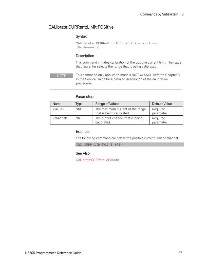
CALibrate:CURRent:LIMit:POSitive
Syntax
CALibrate:CURRent:LIMit:POSitive <value>, (@<channel>)
Description
This command initiates calibration of the positive current limit. The value that you enter selects the range that is being calibrated.
NOTE This command only applies to models N678xA SMU. Refer to Chapter 3 in the Service Guide for a detailed description of the calibration procedure.
Parameters
Name Type Range of Values Default Value <value> NRf The maximum current of the range
that is being calibrated. Required parameter
<channel> NR1 The output channel that is being calibrated.
Required parameter
Example
The following command calibrates the positive current limit of channel 1.
CAL:CURR:LIM:POS 3,(@1)
See Also
CALibrate:CURRent:MEASure
3 Commands by Subsystem
28 N6705 Programmer’s Reference Guide
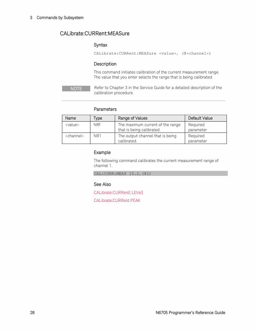
CALibrate:CURRent:MEASure
Syntax
CALibrate:CURRent:MEASure <value>, (@<channel>)
Description
This command initiates calibration of the current measurement range. The value that you enter selects the range that is being calibrated.
NOTE Refer to Chapter 3 in the Service Guide for a detailed description of the calibration procedure.
Parameters
Name Type Range of Values Default Value <value> NRf The maximum current of the range
that is being calibrated. Required parameter
<channel> NR1 The output channel that is being calibrated.
Required parameter
Example
The following command calibrates the current measurement range of channel 1.
CAL:CURR:MEAS 10.2,(@1)
See Also
CALibrate:CURRent[:LEVel]
CALibrate:CURRent:PEAK
Commands by Subsystem 3
N6705 Programmer’s Reference Guide 29
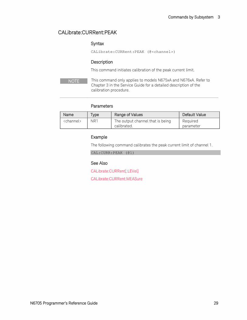
CALibrate:CURRent:PEAK
Syntax
CALibrate:CURRent:PEAK (@<channel>)
Description
This command initiates calibration of the peak current limit.
NOTE This command only applies to models N675xA and N676xA. Refer to Chapter 3 in the Service Guide for a detailed description of the calibration procedure.
Parameters
Name Type Range of Values Default Value <channel> NR1 The output channel that is being
calibrated. Required parameter
Example
The following command calibrates the peak current limit of channel 1.
CAL:CURR:PEAK (@1)
See Also
CALibrate:CURRent[:LEVel]
CALibrate:CURRent:MEASure
3 Commands by Subsystem
30 N6705 Programmer’s Reference Guide
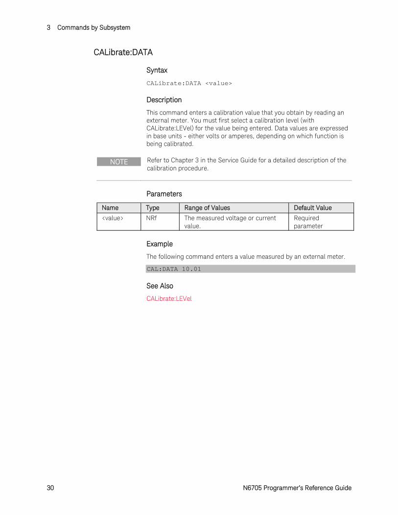
CALibrate:DATA
Syntax
CALibrate:DATA <value>
Description
This command enters a calibration value that you obtain by reading an external meter. You must first select a calibration level (with CALibrate:LEVel) for the value being entered. Data values are expressed in base units - either volts or amperes, depending on which function is being calibrated.
NOTE Refer to Chapter 3 in the Service Guide for a detailed description of the calibration procedure.
Parameters
Name Type Range of Values Default Value <value> NRf The measured voltage or current
value. Required parameter
Example
The following command enters a value measured by an external meter.
CAL:DATA 10.01
See Also
CALibrate:LEVel
Commands by Subsystem 3
N6705 Programmer’s Reference Guide 31
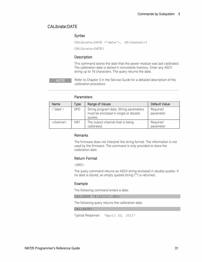
CALibrate:DATE
Syntax
CALibrate:DATE <"date">, (@<channel>)
CALibrate:DATE?
Description
This command stores the date that the power module was last calibrated. The calibration date is stored in nonvolatile memory. Enter any ASCII string up to 16 characters. The query returns the date.
NOTE Refer to Chapter 3 in the Service Guide for a detailed description of the calibration procedure.
Parameters
Name Type Range of Values Default Value <”date”> SPD String program data. String parameters
must be enclosed in single or double quotes.
Required parameter
<channel> NR1 The output channel that is being calibrated.
Required parameter
Remarks
The firmware does not interpret the string format. The information is not used by the firmware. The command is only provided to store the calibration date.
Return Format
<SRD>
The query command returns an ASCII string enclosed in double quotes. If no date is stored, an empty quoted string ("") is returned.
Example
The following command enters a date.
CAL:DATE "4/22/11",(@1)
The following query returns the calibration date.
CAL:DATE?
Typical Response: "April 22, 2011"
3 Commands by Subsystem
32 N6705 Programmer’s Reference Guide
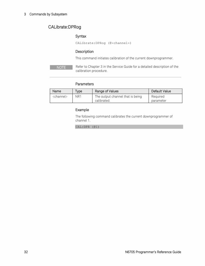
CALibrate:DPRog
Syntax
CALibrate:DPRog (@<channel>)
Description
This command initiates calibration of the current downprogrammer.
NOTE Refer to Chapter 3 in the Service Guide for a detailed description of the calibration procedure.
Parameters
Name Type Range of Values Default Value <channel> NR1 The output channel that is being
calibrated. Required parameter
Example
The following command calibrates the current downprogrammer of channel 1.
CAL:DPR (@1)
Commands by Subsystem 3
N6705 Programmer’s Reference Guide 33
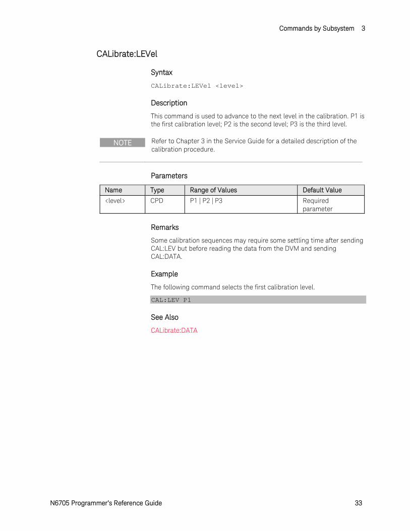
CALibrate:LEVel
Syntax
CALibrate:LEVel <level>
Description
This command is used to advance to the next level in the calibration. P1 is the first calibration level; P2 is the second level; P3 is the third level.
NOTE Refer to Chapter 3 in the Service Guide for a detailed description of the calibration procedure.
Parameters
Name Type Range of Values Default Value <level> CPD P1 | P2 | P3 Required
parameter
Remarks
Some calibration sequences may require some settling time after sending CAL:LEV but before reading the data from the DVM and sending CAL:DATA.
Example
The following command selects the first calibration level.
CAL:LEV P1
See Also
CALibrate:DATA
3 Commands by Subsystem
34 N6705 Programmer’s Reference Guide
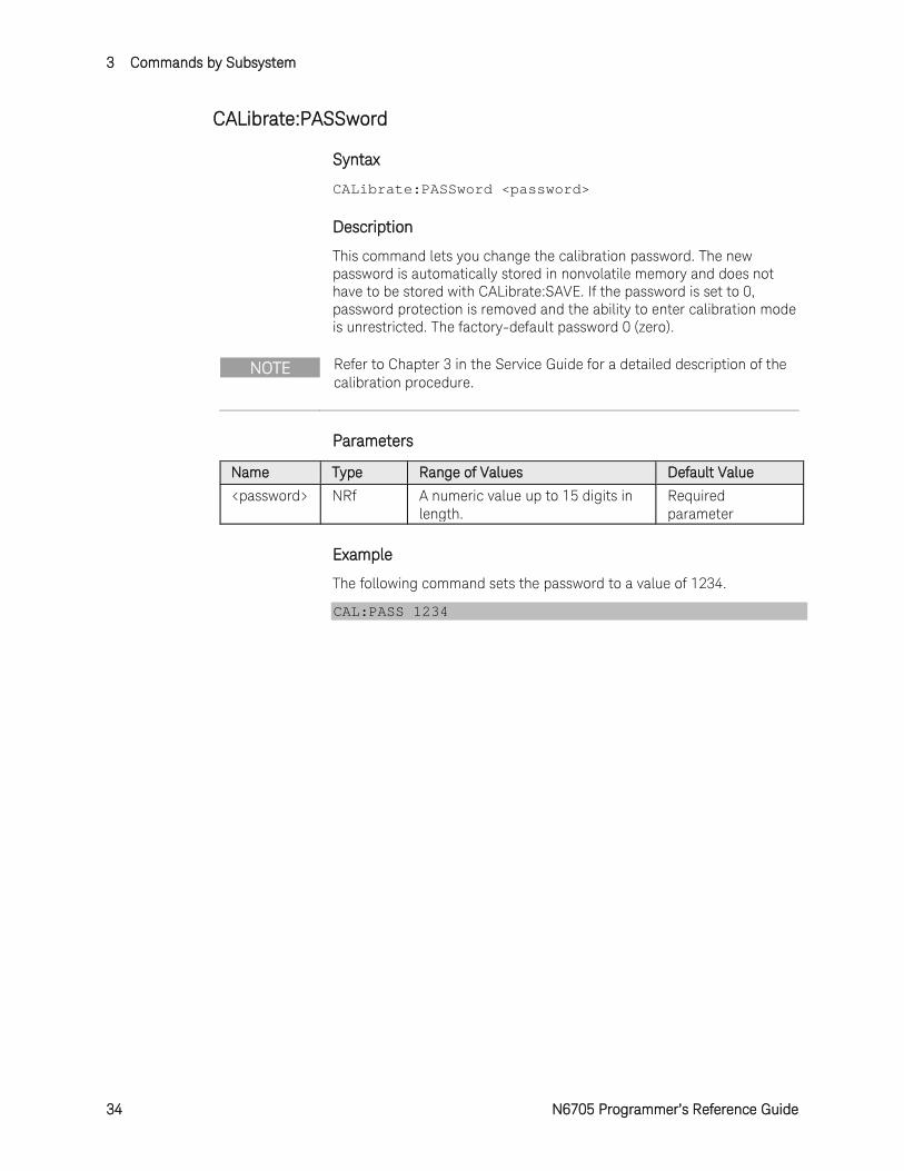
CALibrate:PASSword
Syntax
CALibrate:PASSword <password>
Description
This command lets you change the calibration password. The new password is automatically stored in nonvolatile memory and does not have to be stored with CALibrate:SAVE. If the password is set to 0, password protection is removed and the ability to enter calibration mode is unrestricted. The factory-default password 0 (zero).
NOTE Refer to Chapter 3 in the Service Guide for a detailed description of the calibration procedure.
Parameters
Name Type Range of Values Default Value <password> NRf A numeric value up to 15 digits in
length. Required parameter
Example
The following command sets the password to a value of 1234.
CAL:PASS 1234
Commands by Subsystem 3
N6705 Programmer’s Reference Guide 35
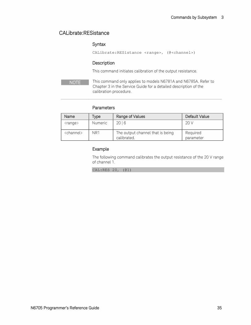
CALibrate:RESistance
Syntax
CALibrate:RESistance <range>, (@<channel>)
Description
This command initiates calibration of the output resistance.
NOTE This command only applies to models N6781A and N6785A. Refer to Chapter 3 in the Service Guide for a detailed description of the calibration procedure.
Parameters
Name Type Range of Values Default Value <range> Numeric 20 | 6 20 V
<channel> NR1 The output channel that is being calibrated.
Required parameter
Example
The following command calibrates the output resistance of the 20 V range of channel 1.
CAL:RES 20, (@1)
3 Commands by Subsystem
36 N6705 Programmer’s Reference Guide
CALibrate:SAVE
Syntax
CALibrate:SAVE
Description
This command saves calibration constants in non-volatile memory after the calibration procedure has been completed. If calibration mode is exited by programming CALibration:STATe OFF without first saving the new constants, the previous constants are restored.
NOTE Refer to Chapter 3 in the Service Guide for a detailed description of the calibration procedure.
Example
The following command saves the calibration values.
CAL:SAVE
See Also
CALibrate:STATe
Commands by Subsystem 3
N6705 Programmer’s Reference Guide 37
CALibrate:STATe
Syntax
CALibrate:STATe <Bool>, [<password>]
CALibrate:STATe?
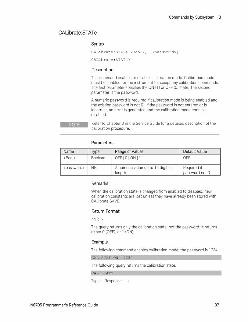
Description
This command enables or disables calibration mode. Calibration mode must be enabled for the instrument to accept any calibration commands. The first parameter specifies the ON (1) or OFF (0) state. The second parameter is the password.
A numeric password is required if calibration mode is being enabled and the existing password is not 0. If the password is not entered or is incorrect, an error is generated and the calibration mode remains disabled.
NOTE Refer to Chapter 3 in the Service Guide for a detailed description of the calibration procedure.
Parameters
Name Type Range of Values Default Value <Bool> Boolean OFF | 0 | ON | 1 OFF
<password> NRf A numeric value up to 15 digits in length.
Required if password not 0
Remarks
When the calibration state is changed from enabled to disabled, new calibration constants are lost unless they have already been stored with CALibrate:SAVE.
Return Format
<NR1>
The query returns only the calibration state, not the password. It returns either 0 (OFF), or 1 (ON).
Example
The following command enables calibration mode; the password is 1234.
CAL:STAT ON, 1234
The following query returns the calibration state.
CAL:STAT?
Typical Response: 1
3 Commands by Subsystem
38 N6705 Programmer’s Reference Guide
See Also
CALibrate:SAVE
Commands by Subsystem 3
N6705 Programmer’s Reference Guide 39
CALibrate:VOLTage[:LEVel]
Syntax
CALibrate:VOLTage[:LEVel] <value>, (@<channel>)
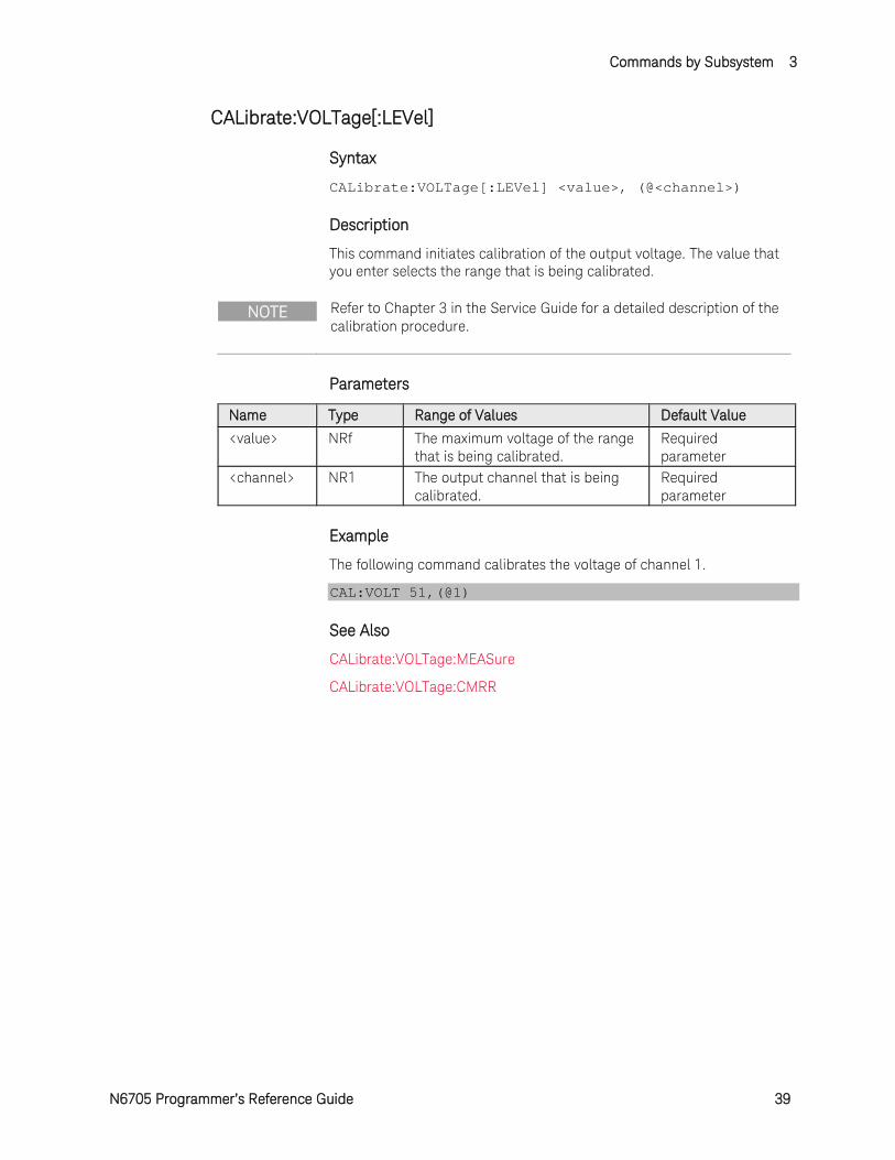
Description
This command initiates calibration of the output voltage. The value that you enter selects the range that is being calibrated.
NOTE Refer to Chapter 3 in the Service Guide for a detailed description of the calibration procedure.
Parameters
Name Type Range of Values Default Value <value> NRf The maximum voltage of the range
that is being calibrated. Required parameter
<channel> NR1 The output channel that is being calibrated.
Required parameter
Example
The following command calibrates the voltage of channel 1.
CAL:VOLT 51,(@1)
See Also
CALibrate:VOLTage:MEASure
CALibrate:VOLTage:CMRR
3 Commands by Subsystem
40 N6705 Programmer’s Reference Guide
CALibrate:VOLTage:CMRR
Syntax
CALibrate:VOLTage:CMRR (@<channel>)
Description
This command initiates calibration of the voltage common mode rejection ratio.
NOTE Refer to Chapter 3 in the Service Guide for a detailed description of the calibration procedure.
Parameters
Name Type Range of Values Default Value <channel> NR1 The output channel that is being
calibrated. Required parameter
Example
The following command calibrates the voltage common mode rejection ratio of channel 1.
CAL:VOLT:CMRR (@1)
See Also
CALibrate:VOLTage[:LEVel]
CALibrate:VOLTage:MEASure
Commands by Subsystem 3
N6705 Programmer’s Reference Guide 41
CALibrate:VOLTage:LIMit:POSitive
Syntax
CALibrate:VOLTage:LIMit:POSitive <value>, (@<channel>)
Description
This command initiates calibration of the positive voltage limit. The value that you enter selects the range that is being calibrated.
NOTE This command only applies to model N678xA SMU. Refer to Chapter 3 in the Service Guide for a detailed description of the calibration procedure.
Parameters
Name Type Range of Values Default Value <value> NRf The maximum voltage of the range
that is being calibrated. Required parameter
<channel> NR1 The output channel that is being calibrated.
Required parameter
Example
The following command calibrates the positive voltage limit of channel 1.
CAL:VOLT:LIM:POS 20,(@1)
See Also
CALibrate:VOLTage:MEASure
3 Commands by Subsystem
42 N6705 Programmer’s Reference Guide
CALibrate:VOLTage:MEASure
Syntax
CALibrate:VOLTage:MEASure <value>, (@<channel>)
Description
This command initiates calibration of the voltage measurement range. The value that you enter selects the range that is being calibrated.
NOTE Refer to Chapter 3 in the Service Guide for a detailed description of the calibration procedure.
Parameters
Name Type Range of Values Default Value <value> NRf The maximum voltage of the range
that is being calibrated. Required parameter
<channel> NR1 The output channel that is being calibrated.
Required parameter
Example
The following command calibrates the voltage measurement range of channel 1.
CAL:VOLT:MEAS 51,(@1)
See Also
CALibrate:VOLTage[:LEVel]
CALibrate:VOLTage:CMRR
Commands by Subsystem 3
N6705 Programmer’s Reference Guide 43
CALibrate:VOLTage:MEASure:AUXiliary
Syntax
CALibrate:VOLTage:MEASure:AUXiliary (@<channel>)
Description
This command initiates calibration of the auxiliary voltage measurement input.
NOTE This command only applies to models N6781A and N6785A. Refer to Chapter 3 in the Service Guide for a detailed description of the calibration procedure.
Parameters
Name Type Range of Values Default Value <channel> NR1 The output channel that is being
calibrated. Required parameter
Example
The following command calibrates the auxiliary voltage measurement input of channel 1.
CAL:VOLT:MEAS:AUX (@1)
3 Commands by Subsystem
44 N6705 Programmer’s Reference Guide
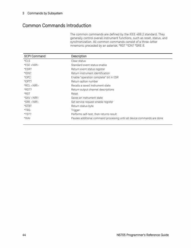
Common Commands Introduction
The common commands are defined by the IEEE 488.2 standard. They generally control overall instrument functions, such as reset, status, and synchronization. All common commands consist of a three-letter mnemonic preceded by an asterisk: *RST *IDN? *SRE 8.
SCPI Command Description
*CLS Clear status *ESE <NRf> Standard event status enable *ESR? Return event status register *IDN? Return instrument identification *OPC Enable "operation complete" bit in ESR *OPT? Return option number *RCL <NRf> Recalls a saved instrument state *RDT? Return output channel descriptions *RST Reset *SAV <NRf> Saves an instrument state *SRE <NRf> Set service request enable register *STB? Return status byte *TRG Trigger *TST? Performs self-test, then returns result *WAI Pauses additional command processing until all device commands are done
Commands by Subsystem 3
N6705 Programmer’s Reference Guide 45
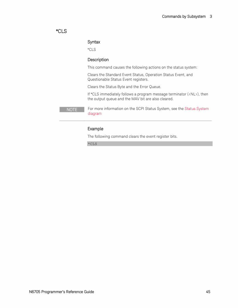
*CLS
Syntax
*CLS
Description
This command causes the following actions on the status system:
Clears the Standard Event Status, Operation Status Event, and Questionable Status Event registers.
Clears the Status Byte and the Error Queue.
If *CLS immediately follows a program message terminator (<NL>), then the output queue and the MAV bit are also cleared.
NOTE For more information on the SCPI Status System, see the Status System diagram
Example
The following command clears the event register bits.
*CLS
3 Commands by Subsystem
46 N6705 Programmer’s Reference Guide
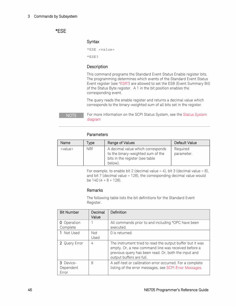
*ESE
Syntax
*ESE <value>
*ESE?
Description
This command programs the Standard Event Status Enable register bits. The programming determines which events of the Standard Event Status Event register (see *ESR?) are allowed to set the ESB (Event Summary Bit) of the Status Byte register. A 1 in the bit position enables the corresponding event.
The query reads the enable register and returns a decimal value which corresponds to the binary-weighted sum of all bits set in the register.
NOTE For more information on the SCPI Status System, see the Status System diagram
Parameters
Name Type Range of Values Default Value
<value> NRf A decimal value which corresponds to the binary-weighted sum of the bits in the register (see table below).
Required parameter.
For example, to enable bit 2 (decimal value = 4), bit 3 (decimal value = 8), and bit 7 (decimal value = 128), the corresponding decimal value would be 140 (4 + 8 + 128).
Remarks
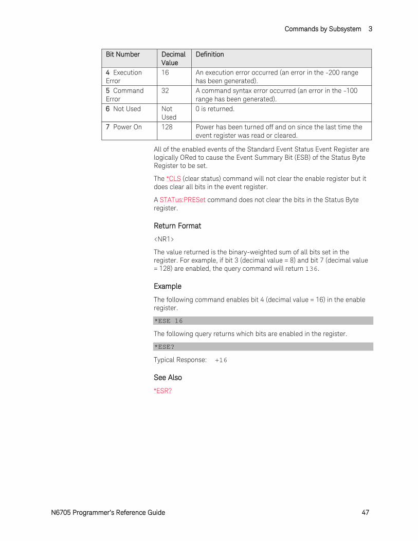
The following table lists the bit definitions for the Standard Event Register.
Bit Number Decimal Value
Definition
0 Operation Complete
1 All commands prior to and including *OPC have been executed.
1 Not Used Not Used
0 is returned.
2 Query Error 4 The instrument tried to read the output buffer but it was empty. Or, a new command line was received before a previous query has been read. Or, both the input and output buffers are full.
3 Device-Dependent Error
8 A self-test or calibration error occurred. For a complete listing of the error messages, see SCPI Error Messages.
Commands by Subsystem 3
N6705 Programmer’s Reference Guide 47
Bit Number Decimal Value
Definition
4 Execution Error
16 An execution error occurred (an error in the -200 range has been generated).
5 Command Error
32 A command syntax error occurred (an error in the -100 range has been generated).
6 Not Used Not Used
0 is returned.
7 Power On 128 Power has been turned off and on since the last time the event register was read or cleared.
All of the enabled events of the Standard Event Status Event Register are logically ORed to cause the Event Summary Bit (ESB) of the Status Byte Register to be set.
The *CLS (clear status) command will not clear the enable register but it does clear all bits in the event register.
A STATus:PRESet command does not clear the bits in the Status Byte register.
Return Format
<NR1>
The value returned is the binary-weighted sum of all bits set in the register. For example, if bit 3 (decimal value = 8) and bit 7 (decimal value = 128) are enabled, the query command will return 136.
Example
The following command enables bit 4 (decimal value = 16) in the enable register.
*ESE 16
The following query returns which bits are enabled in the register.
*ESE?
Typical Response: +16
See Also
*ESR?
3 Commands by Subsystem
48 N6705 Programmer’s Reference Guide
*ESR?
Syntax
*ESR?
Description
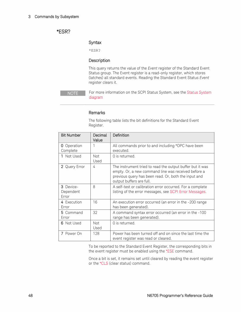
This query returns the value of the Event register of the Standard Event Status group. The Event register is a read-only register, which stores (latches) all standard events. Reading the Standard Event Status Event register clears it.
NOTE For more information on the SCPI Status System, see the Status System diagram
Remarks
The following table lists the bit definitions for the Standard Event Register.
Bit Number Decimal Value
Definition
0 Operation Complete
1 All commands prior to and including *OPC have been executed.
1 Not Used Not Used
0 is returned.
2 Query Error 4 The instrument tried to read the output buffer but it was empty. Or, a new command line was received before a previous query has been read. Or, both the input and output buffers are full.
3 Device-Dependent Error
8 A self-test or calibration error occurred. For a complete listing of the error messages, see SCPI Error Messages.
4 Execution Error
16 An execution error occurred (an error in the -200 range has been generated).
5 Command Error
32 A command syntax error occurred (an error in the -100 range has been generated).
6 Not Used Not Used
0 is returned.
7 Power On 128 Power has been turned off and on since the last time the event register was read or cleared.
To be reported to the Standard Event Register, the corresponding bits in the event register must be enabled using the *ESE command.
Once a bit is set, it remains set until cleared by reading the event register or the *CLS (clear status) command.
Commands by Subsystem 3
N6705 Programmer’s Reference Guide 49
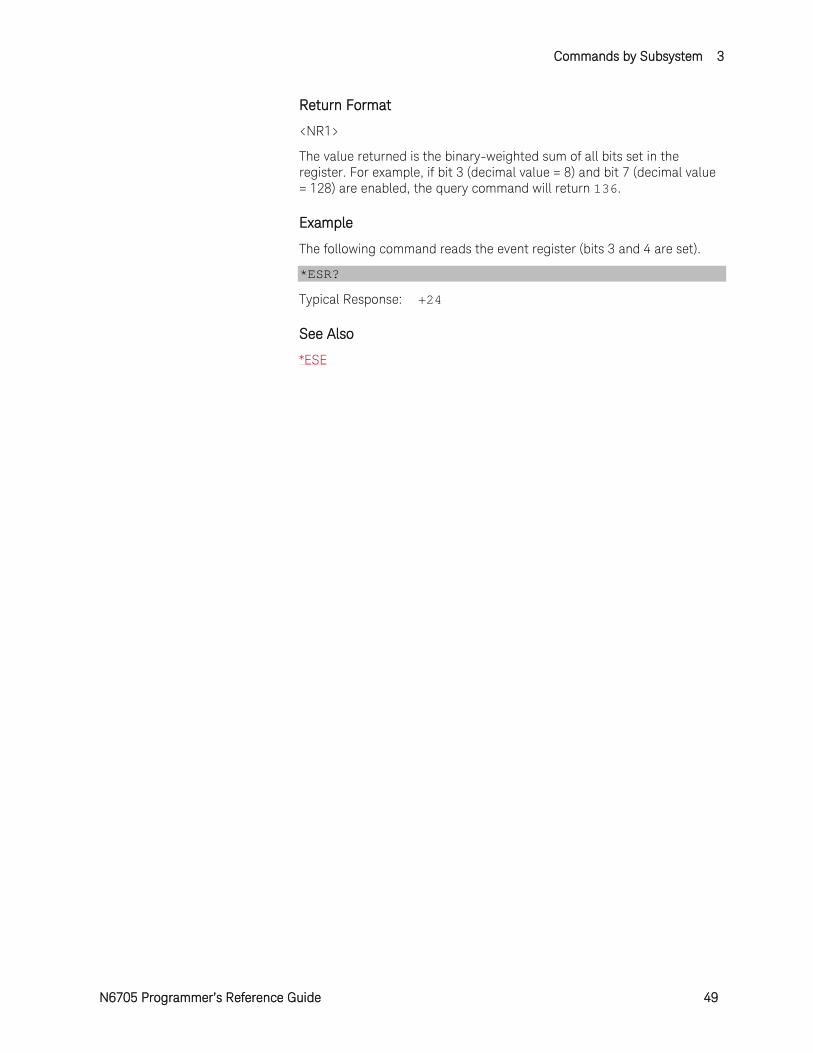
Return Format
<NR1>
The value returned is the binary-weighted sum of all bits set in the register. For example, if bit 3 (decimal value = 8) and bit 7 (decimal value = 128) are enabled, the query command will return 136.
Example
The following command reads the event register (bits 3 and 4 are set).
*ESR?
Typical Response: +24
See Also
*ESE
3 Commands by Subsystem
50 N6705 Programmer’s Reference Guide
*IDN?
Syntax
*IDN?
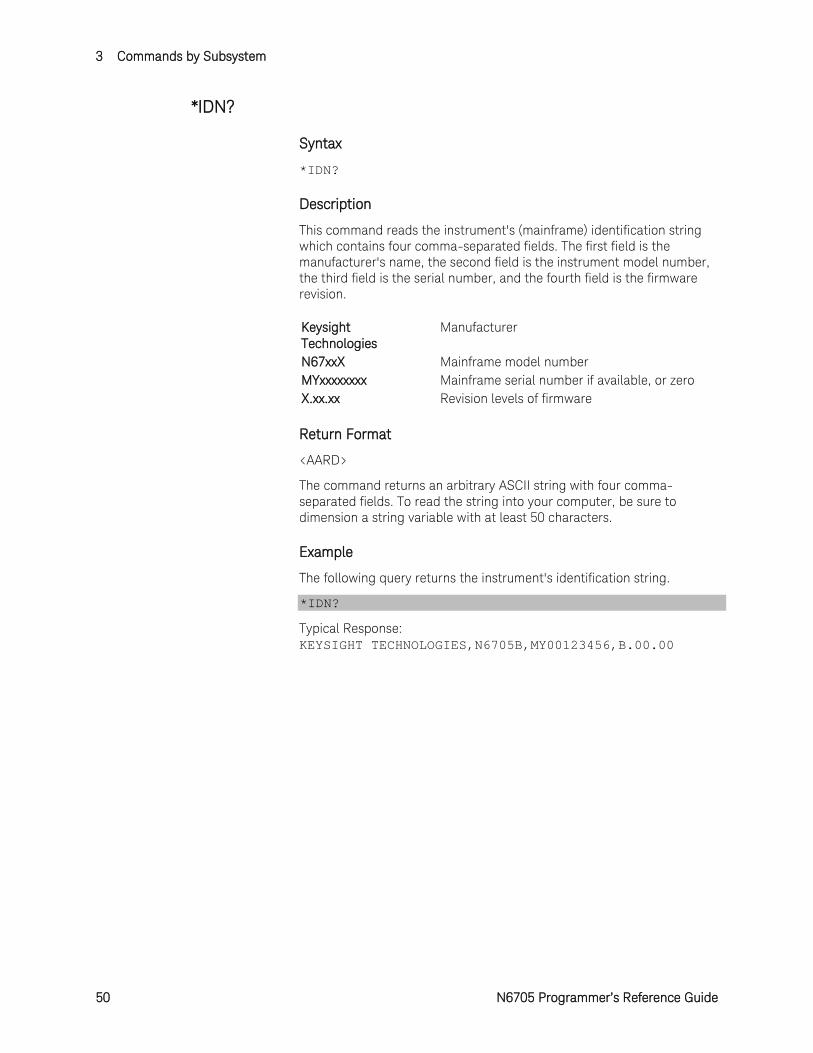
Description
This command reads the instrument's (mainframe) identification string which contains four comma-separated fields. The first field is the manufacturer's name, the second field is the instrument model number, the third field is the serial number, and the fourth field is the firmware revision. Keysight Technologies
Manufacturer
N67xxX Mainframe model number MYxxxxxxxx Mainframe serial number if available, or zero X.xx.xx Revision levels of firmware
Return Format
<AARD>
The command returns an arbitrary ASCII string with four comma-separated fields. To read the string into your computer, be sure to dimension a string variable with at least 50 characters.
Example
The following query returns the instrument's identification string.
*IDN?
Typical Response: KEYSIGHT TECHNOLOGIES,N6705B,MY00123456,B.00.00
Commands by Subsystem 3
N6705 Programmer’s Reference Guide 51
*OPC
Syntax
*OPC
*OPC?
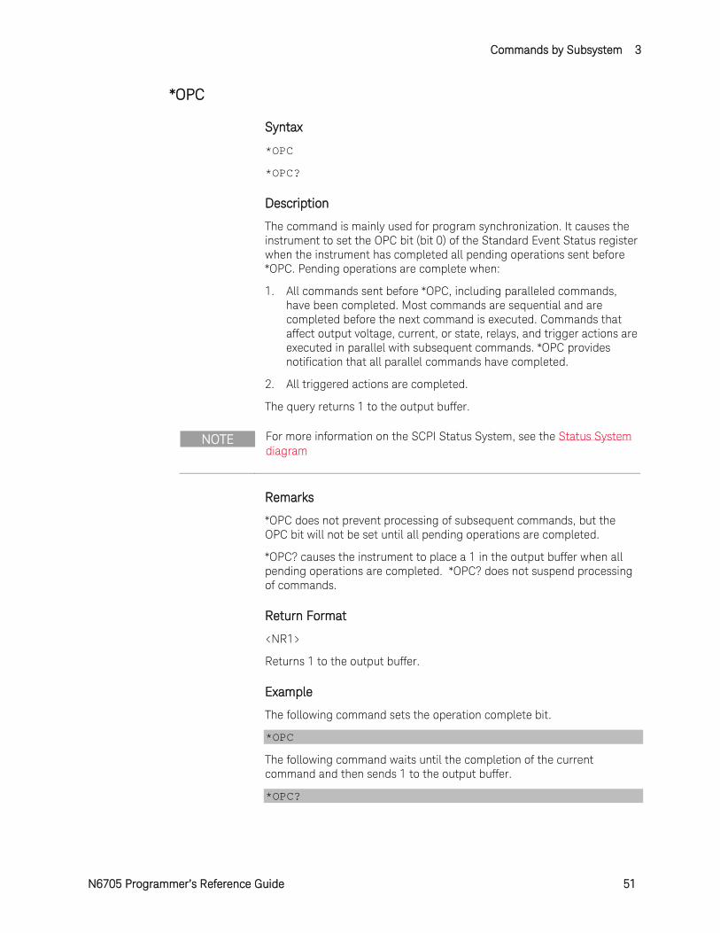
Description
The command is mainly used for program synchronization. It causes the instrument to set the OPC bit (bit 0) of the Standard Event Status register when the instrument has completed all pending operations sent before *OPC. Pending operations are complete when:
1. All commands sent before *OPC, including paralleled commands, have been completed. Most commands are sequential and are completed before the next command is executed. Commands that affect output voltage, current, or state, relays, and trigger actions are executed in parallel with subsequent commands. *OPC provides notification that all parallel commands have completed.
2. All triggered actions are completed.
The query returns 1 to the output buffer.
NOTE For more information on the SCPI Status System, see the Status System diagram
Remarks
*OPC does not prevent processing of subsequent commands, but the OPC bit will not be set until all pending operations are completed.
*OPC? causes the instrument to place a 1 in the output buffer when all pending operations are completed. *OPC? does not suspend processing of commands.
Return Format
<NR1>
Returns 1 to the output buffer.
Example
The following command sets the operation complete bit.
*OPC
The following command waits until the completion of the current command and then sends 1 to the output buffer.
*OPC?
3 Commands by Subsystem
52 N6705 Programmer’s Reference Guide
*OPT?
Syntax
*OPT?
Description
This query requests the mainframe to identify any installed options.
Remarks
A 0 indicates no options are installed.
Return Format
<CRD>
The option number.
Example
The following command returns the option number.
*OPT?
Typical Response: +0
Commands by Subsystem 3
N6705 Programmer’s Reference Guide 53
*RCL
Syntax
*RCL 0 | 1
Description
This command restores the instrument to a state that was previously stored in memory locations 0 through 1 with the *SAV command. All instrument states are recalled except for the following:
The trigger system is set to the Idle state by an implied ABORt command (this cancels any uncompleted trigger actions).
Calibration is disabled by setting CALibration:STATe to OFF.
All list settings are set to their *RST values.
Remarks
The device state stored in location 0 is automatically recalled at power turn-on when the Output Power-On state is set to RCL 0.
You cannot recall the instrument state from a storage location that is empty or was deleted. You can only recall a state from a location that contains a previously stored state.
A Factory Reset (*RST command) does not affect the configurations stored in memory. Once a state is stored, it remains until it is overwritten or specifically deleted.
Example
The following command recalls the instrument state previously stored in location 1.
*RCL 1
See Also
*SAV
*RST
3 Commands by Subsystem
54 N6705 Programmer’s Reference Guide
*RDT?
Syntax
*RDT?
Description
This query returns a description of all the power modules (channels) installed in a mainframe. Semicolons separate multiple channel descriptions.
CHAN<c>:description <c> refers to the channel number. Description returns the model number of the power modules.
Return Format
<AARD>
The command returns an arbitrary ASCII string with up to four semicolon-separated fields. To read the string into your computer, be sure to dimension a string variable with at least 50 characters.
Example
The following query identifies the mainframe's installed power modules.
*RDT?
Typical Response: CHAN1:N6751A;CHAN2:N6752A
Commands by Subsystem 3
N6705 Programmer’s Reference Guide 55
*RST
Syntax
*RST
Description
This command resets the volatile memory of the instrument to a factory-defined state. Refer to Factory Reset State for a complete listing of the instrument's factory configuration.
Remarks
*RST also forces the ABORt:ACQuire and ABORt:TRANsient commands. This cancels any measurement or output trigger actions presently in process, and resets the two WTG bits in the Status Operation Condition register.
Example
The following command resets the instrument.
*RST
See Also
ABORt:ACQuire
ABORT:DLOG
ABORt::ELOG
ABORt:TRANsient
3 Commands by Subsystem
56 N6705 Programmer’s Reference Guide
*SAV
Syntax
*SAV 0 | 1
Description
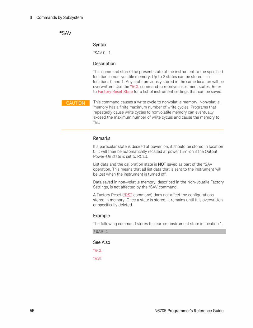
This command stores the present state of the instrument to the specified location in non-volatile memory. Up to 2 states can be stored - in locations 0 and 1. Any state previously stored in the same location will be overwritten. Use the *RCL command to retrieve instrument states. Refer to Factory Reset State for a list of instrument settings that can be saved.
CAUTION This command causes a write cycle to nonvolatile memory. Nonvolatile memory has a finite maximum number of write cycles. Programs that repeatedly cause write cycles to nonvolatile memory can eventually exceed the maximum number of write cycles and cause the memory to fail.
Remarks
If a particular state is desired at power-on, it should be stored in location 0. It will then be automatically recalled at power turn-on if the Output Power-On state is set to RCL0.
List data and the calibration state is NOT saved as part of the *SAV operation. This means that all list data that is sent to the instrument will be lost when the instrument is turned off.
Data saved in non-volatile memory, described in the Non-volatile Factory Settings, is not affected by the *SAV command.
A Factory Reset (*RST command) does not affect the configurations stored in memory. Once a state is stored, it remains until it is overwritten or specifically deleted.
Example
The following command stores the current instrument state in location 1.
*SAV 1
See Also
*RCL
*RST
Commands by Subsystem 3
N6705 Programmer’s Reference Guide 57
*SRE
Syntax
*SRE <value>
*SRE?
Description
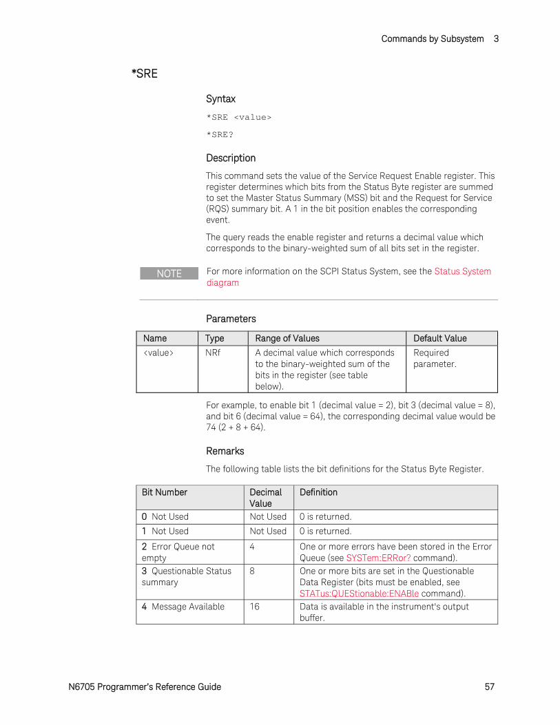
This command sets the value of the Service Request Enable register. This register determines which bits from the Status Byte register are summed to set the Master Status Summary (MSS) bit and the Request for Service (RQS) summary bit. A 1 in the bit position enables the corresponding event.
The query reads the enable register and returns a decimal value which corresponds to the binary-weighted sum of all bits set in the register.
NOTE For more information on the SCPI Status System, see the Status System diagram
Parameters
Name Type Range of Values Default Value
<value> NRf A decimal value which corresponds to the binary-weighted sum of the bits in the register (see table below).
Required parameter.
For example, to enable bit 1 (decimal value = 2), bit 3 (decimal value = 8), and bit 6 (decimal value = 64), the corresponding decimal value would be 74 (2 + 8 + 64).
Remarks
The following table lists the bit definitions for the Status Byte Register.
Bit Number Decimal Value
Definition
0 Not Used Not Used 0 is returned.
1 Not Used Not Used 0 is returned.
2 Error Queue not empty
4 One or more errors have been stored in the Error Queue (see SYSTem:ERRor? command).
3 Questionable Status summary
8 One or more bits are set in the Questionable Data Register (bits must be enabled, see STATus:QUEStionable:ENABle command).
4 Message Available 16 Data is available in the instrument's output buffer.
3 Commands by Subsystem
58 N6705 Programmer’s Reference Guide
Bit Number Decimal
Value Definition
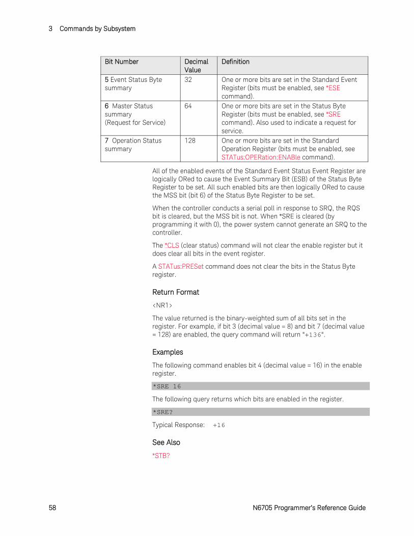
5 Event Status Byte summary
32 One or more bits are set in the Standard Event Register (bits must be enabled, see *ESE command).
6 Master Status summary (Request for Service)
64 One or more bits are set in the Status Byte Register (bits must be enabled, see *SRE command). Also used to indicate a request for service.
7 Operation Status summary
128 One or more bits are set in the Standard Operation Register (bits must be enabled, see STATus:OPERation:ENABle command).
All of the enabled events of the Standard Event Status Event Register are logically ORed to cause the Event Summary Bit (ESB) of the Status Byte Register to be set. All such enabled bits are then logically ORed to cause the MSS bit (bit 6) of the Status Byte Register to be set.
When the controller conducts a serial poll in response to SRQ, the RQS bit is cleared, but the MSS bit is not. When *SRE is cleared (by programming it with 0), the power system cannot generate an SRQ to the controller.
The *CLS (clear status) command will not clear the enable register but it does clear all bits in the event register.
A STATus:PRESet command does not clear the bits in the Status Byte register.
Return Format
<NR1>
The value returned is the binary-weighted sum of all bits set in the register. For example, if bit 3 (decimal value = 8) and bit 7 (decimal value = 128) are enabled, the query command will return "+136".
Examples
The following command enables bit 4 (decimal value = 16) in the enable register.
*SRE 16
The following query returns which bits are enabled in the register.
*SRE?
Typical Response: +16
See Also
*STB?
Commands by Subsystem 3
N6705 Programmer’s Reference Guide 59
*STB?
Syntax
*STB?
Description
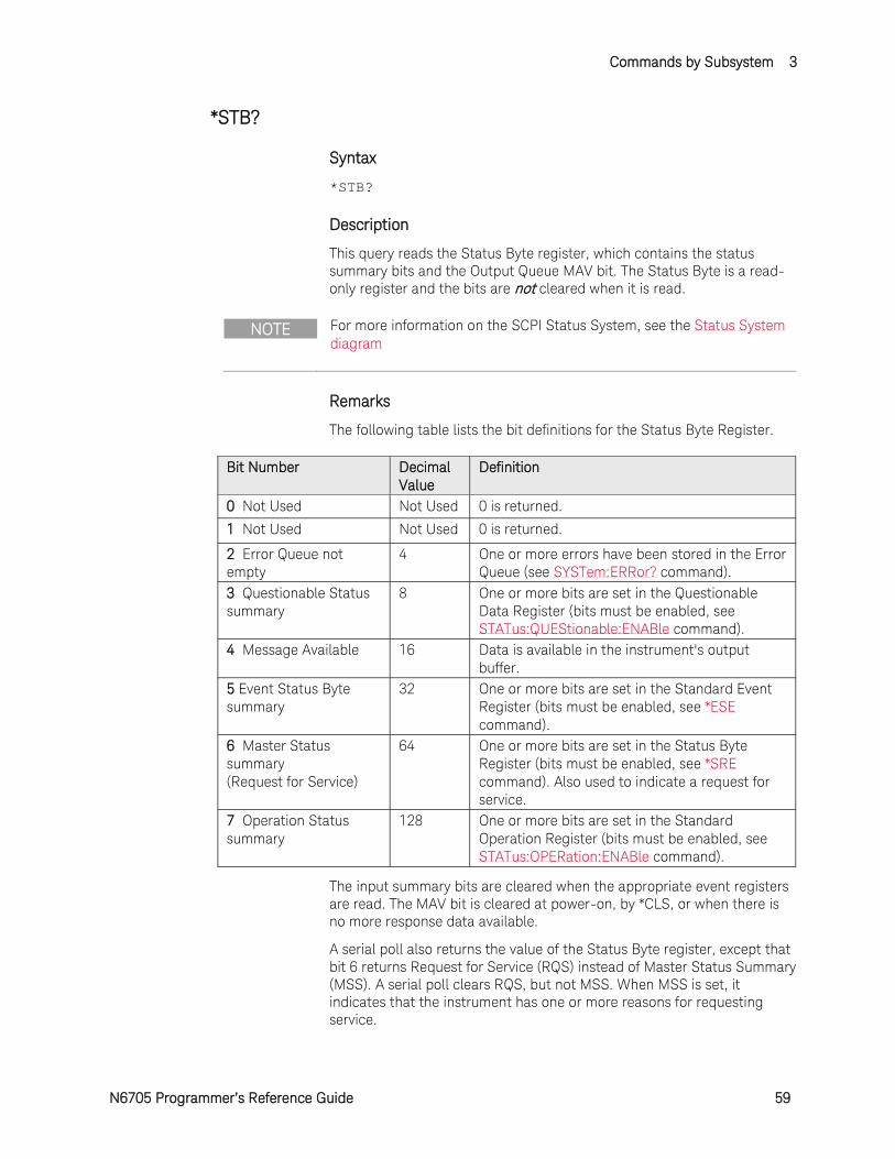
This query reads the Status Byte register, which contains the status summary bits and the Output Queue MAV bit. The Status Byte is a read-only register and the bits are not cleared when it is read.
NOTE For more information on the SCPI Status System, see the Status System diagram
Remarks
The following table lists the bit definitions for the Status Byte Register.
Bit Number Decimal Value
Definition
0 Not Used Not Used 0 is returned.
1 Not Used Not Used 0 is returned.
2 Error Queue not empty
4 One or more errors have been stored in the Error Queue (see SYSTem:ERRor? command).
3 Questionable Status summary
8 One or more bits are set in the Questionable Data Register (bits must be enabled, see STATus:QUEStionable:ENABle command).
4 Message Available 16 Data is available in the instrument's output buffer.
5 Event Status Byte summary
32 One or more bits are set in the Standard Event Register (bits must be enabled, see *ESE command).
6 Master Status summary (Request for Service)
64 One or more bits are set in the Status Byte Register (bits must be enabled, see *SRE command). Also used to indicate a request for service.
7 Operation Status summary
128 One or more bits are set in the Standard Operation Register (bits must be enabled, see STATus:OPERation:ENABle command).
The input summary bits are cleared when the appropriate event registers are read. The MAV bit is cleared at power-on, by *CLS, or when there is no more response data available.
A serial poll also returns the value of the Status Byte register, except that bit 6 returns Request for Service (RQS) instead of Master Status Summary (MSS). A serial poll clears RQS, but not MSS. When MSS is set, it indicates that the instrument has one or more reasons for requesting service.
3 Commands by Subsystem
60 N6705 Programmer’s Reference Guide
Return Format
<NR1>
The value returned is the binary-weighted sum of all bits set in the register. For example, if bit 1 (decimal value = 2) and bit 4 (decimal value = 16) are set (and the corresponding bits are enabled), this command will return 18.
Example
The following command reads the condition register (bits 3 and 4 are set).
*STB?
Typical Response: +24
See Also
*SRE
Commands by Subsystem 3
N6705 Programmer’s Reference Guide 61
*TRG
Syntax
*TRG
Description
This common command generates a trigger when the trigger subsystem has BUS selected as its source. The command has the same affect as the Group Execute Trigger (<GET>) command.
Example
The following command generates a trigger.
*TRG
See Also
INITiate[:IMMediate]:ACQuire
INITiate[:IMMediate]:TRANsient
INITiate[:IMMediate]:DLOG
INITiate[:IMMediate]:ELOG
3 Commands by Subsystem
62 N6705 Programmer’s Reference Guide
*TST?
Syntax
*TST?
Description
This query causes the instrument to do a self-test and report any errors. A 0 indicates the instrument passed self-test. If all tests pass, you can have a high confidence that the instrument is operational.
Remarks
If one or more tests fail, a 1 is returned and an error is stored in the error queue. For a complete listing of the error messages related to self-test failures, see SCPI Error Messages.
If one or more tests fail, see the Service Guide for instructions on returning the instrument to Keysight for service.
*TST? also forces an *RST command.
Return Format
<NR1>
The command returns 0 (all tests passed) or 1 (one or more tests failed).
Example
The following command performs a self-test and returns a pass/fail indication.
*TST?
Typical Response: +0

Commands by Subsystem 3
N6705 Programmer’s Reference Guide 63
*WAI
Syntax
*WAI
Description
This command instructs the instrument not to process any further commands until all pending operations are completed. Pending operations are as defined under the *OPC command.
Remarks
*WAI can be aborted only by sending the instrument a Device Clear command.
Example
The following command waits for pending operations to complete.
*WAI
See Also
*OPC
3 Commands by Subsystem
64 N6705 Programmer’s Reference Guide
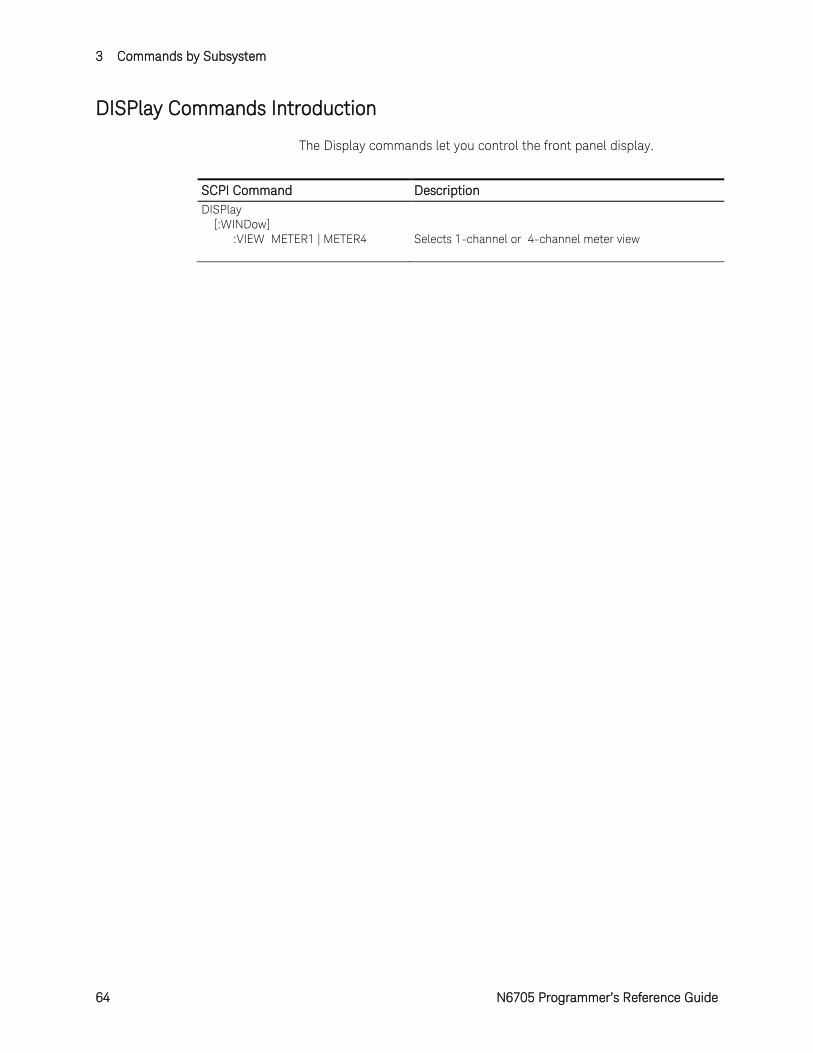
DISPlay Commands Introduction
The Display commands let you control the front panel display.
SCPI Command Description DISPlay [:WINDow] :VIEW METER1 | METER4 Selects 1-channel or 4-channel meter view
Commands by Subsystem 3
N6705 Programmer’s Reference Guide 65
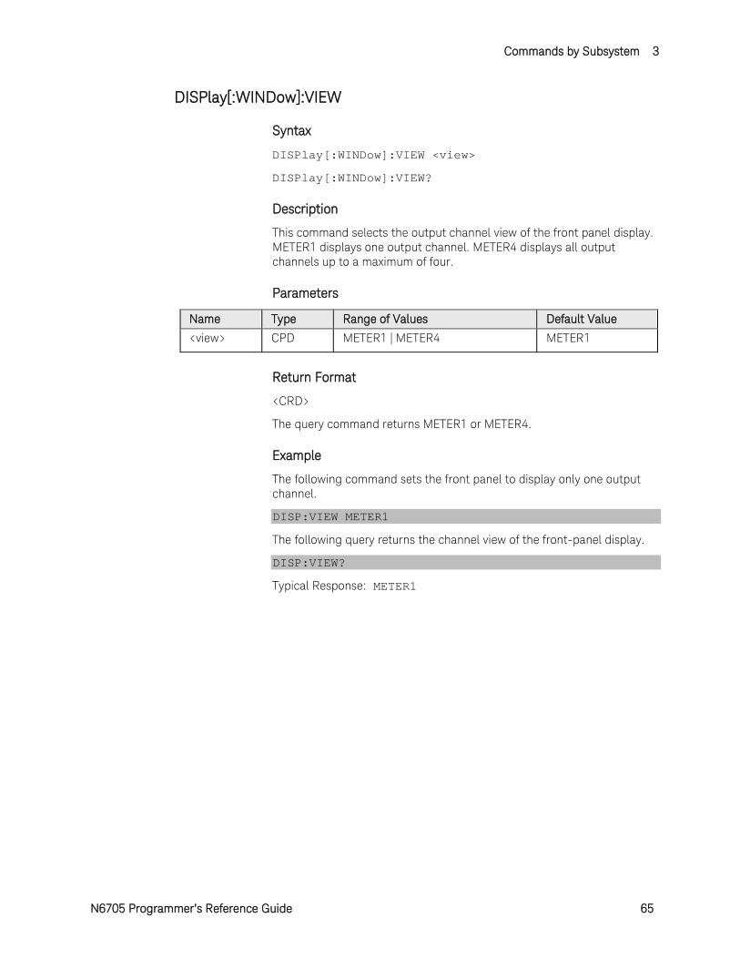
DISPlay[:WINDow]:VIEW
Syntax
DISPlay[:WINDow]:VIEW <view>
DISPlay[:WINDow]:VIEW?
Description
This command selects the output channel view of the front panel display. METER1 displays one output channel. METER4 displays all output channels up to a maximum of four.
Parameters
Name Type Range of Values Default Value
<view> CPD METER1 | METER4 METER1
Return Format
<CRD>
The query command returns METER1 or METER4.
Example
The following command sets the front panel to display only one output channel.
DISP:VIEW METER1
The following query returns the channel view of the front-panel display.
DISP:VIEW?
Typical Response: METER1
3 Commands by Subsystem
66 N6705 Programmer’s Reference Guide
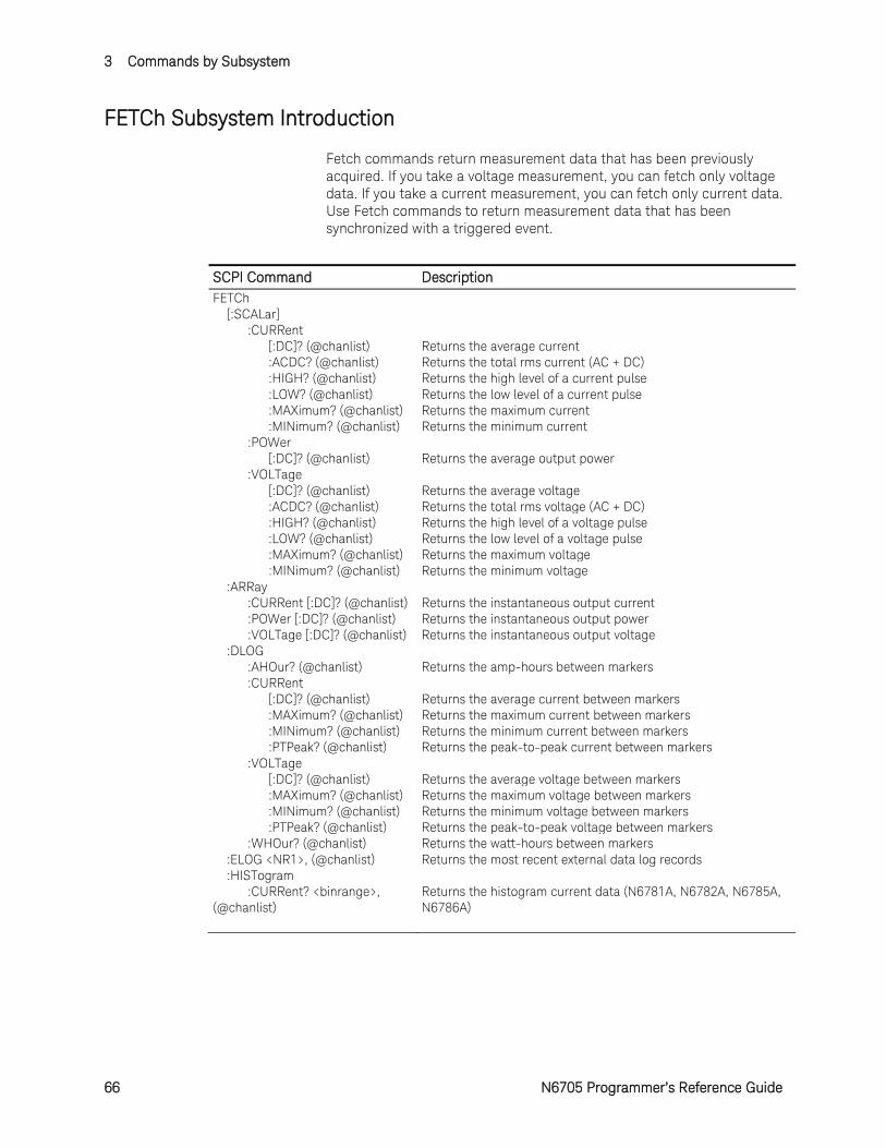
FETCh Subsystem Introduction
Fetch commands return measurement data that has been previously acquired. If you take a voltage measurement, you can fetch only voltage data. If you take a current measurement, you can fetch only current data. Use Fetch commands to return measurement data that has been synchronized with a triggered event.
SCPI Command Description FETCh [:SCALar] :CURRent [:DC]? (@chanlist) Returns the average current :ACDC? (@chanlist) Returns the total rms current (AC + DC) :HIGH? (@chanlist) Returns the high level of a current pulse :LOW? (@chanlist) Returns the low level of a current pulse :MAXimum? (@chanlist) Returns the maximum current :MINimum? (@chanlist) Returns the minimum current :POWer [:DC]? (@chanlist) Returns the average output power :VOLTage [:DC]? (@chanlist) Returns the average voltage :ACDC? (@chanlist) Returns the total rms voltage (AC + DC) :HIGH? (@chanlist) Returns the high level of a voltage pulse :LOW? (@chanlist) Returns the low level of a voltage pulse :MAXimum? (@chanlist) Returns the maximum voltage :MINimum? (@chanlist) Returns the minimum voltage :ARRay :CURRent [:DC]? (@chanlist) Returns the instantaneous output current :POWer [:DC]? (@chanlist) Returns the instantaneous output power :VOLTage [:DC]? (@chanlist) Returns the instantaneous output voltage :DLOG :AHOur? (@chanlist) Returns the amp-hours between markers :CURRent [:DC]? (@chanlist) Returns the average current between markers :MAXimum? (@chanlist) Returns the maximum current between markers :MINimum? (@chanlist) Returns the minimum current between markers :PTPeak? (@chanlist) Returns the peak-to-peak current between markers :VOLTage [:DC]? (@chanlist) Returns the average voltage between markers :MAXimum? (@chanlist) Returns the maximum voltage between markers :MINimum? (@chanlist) Returns the minimum voltage between markers :PTPeak? (@chanlist) Returns the peak-to-peak voltage between markers :WHOur? (@chanlist) Returns the watt-hours between markers :ELOG <NR1>, (@chanlist) Returns the most recent external data log records :HISTogram :CURRent? <binrange>, (@chanlist)
Returns the histogram current data (N6781A, N6782A, N6785A, N6786A)
Commands by Subsystem 3
N6705 Programmer’s Reference Guide 67
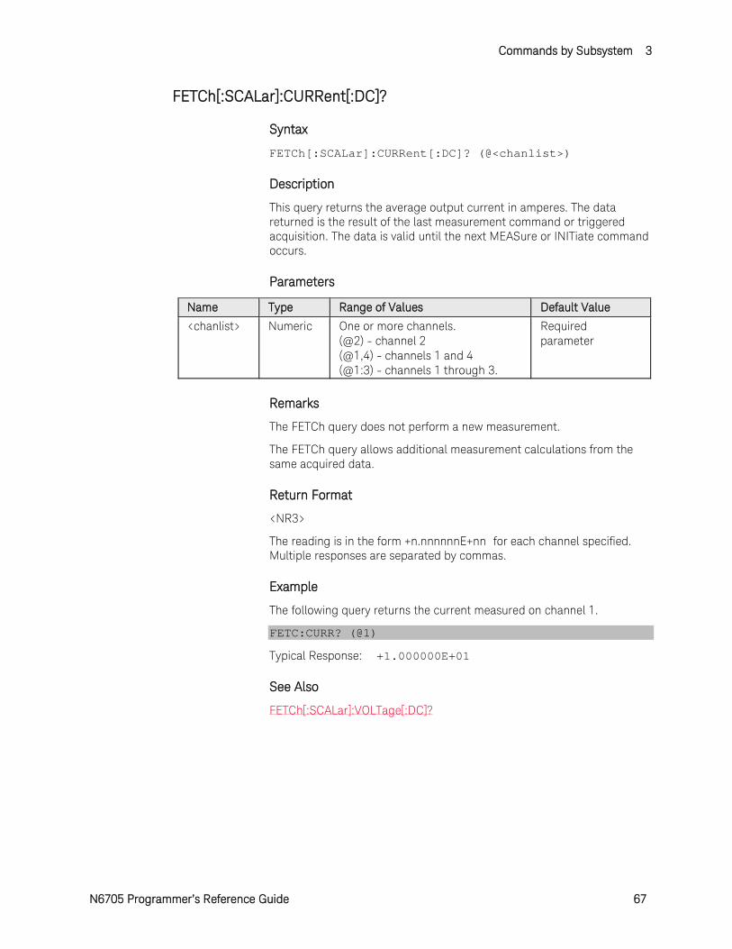
FETCh[:SCALar]:CURRent[:DC]?
Syntax
FETCh[:SCALar]:CURRent[:DC]? (@<chanlist>)
Description
This query returns the average output current in amperes. The data returned is the result of the last measurement command or triggered acquisition. The data is valid until the next MEASure or INITiate command occurs.
Parameters
Name Type Range of Values Default Value <chanlist> Numeric One or more channels.
(@2) - channel 2 (@1,4) - channels 1 and 4 (@1:3) - channels 1 through 3.
Required parameter
Remarks
The FETCh query does not perform a new measurement.
The FETCh query allows additional measurement calculations from the same acquired data.
Return Format
<NR3>
The reading is in the form +n.nnnnnnE+nn for each channel specified. Multiple responses are separated by commas.
Example
The following query returns the current measured on channel 1.
FETC:CURR? (@1)
Typical Response: +1.000000E+01
See Also
FETCh[:SCALar]:VOLTage[:DC]?
3 Commands by Subsystem
68 N6705 Programmer’s Reference Guide
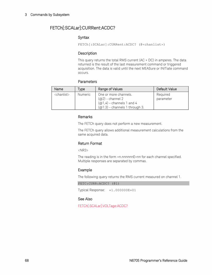
FETCh[:SCALar]:CURRent:ACDC?
Syntax
FETCh[:SCALar]:CURRent:ACDC? (@<chanlist>)
Description
This query returns the total RMS current (AC + DC) in amperes. The data returned is the result of the last measurement command or triggered acquisition. The data is valid until the next MEASure or INITiate command occurs.
Parameters
Name Type Range of Values Default Value <chanlist> Numeric One or more channels.
(@2) - channel 2 (@1,4) - channels 1 and 4 (@1:3) - channels 1 through 3.
Required parameter
Remarks
The FETCh query does not perform a new measurement.
The FETCh query allows additional measurement calculations from the same acquired data.
Return Format
<NR3>
The reading is in the form +n.nnnnnnE+nn for each channel specified. Multiple responses are separated by commas.
Example
The following query returns the RMS current measured on channel 1.
FETC:CURR:ACDC? (@1)
Typical Response: +1.000000E+01
See Also
FETCh[:SCALar]:VOLTage:ACDC?
Commands by Subsystem 3
N6705 Programmer’s Reference Guide 69
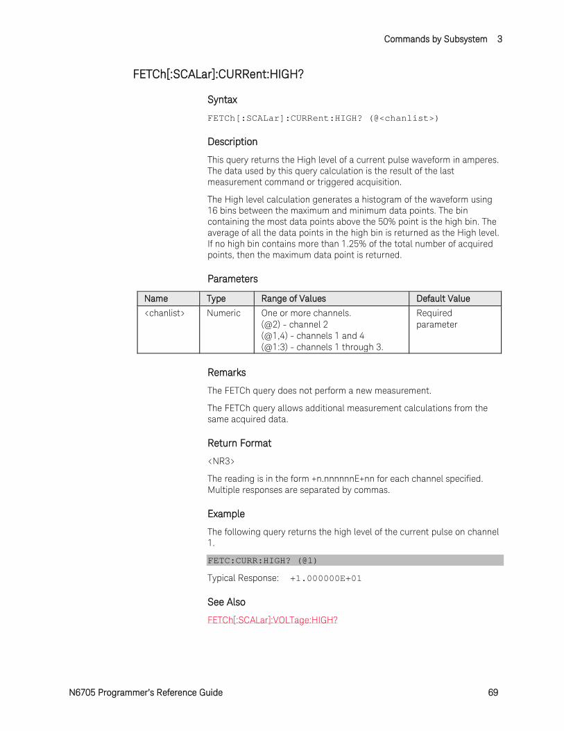
FETCh[:SCALar]:CURRent:HIGH?
Syntax
FETCh[:SCALar]:CURRent:HIGH? (@<chanlist>)
Description
This query returns the High level of a current pulse waveform in amperes. The data used by this query calculation is the result of the last measurement command or triggered acquisition.
The High level calculation generates a histogram of the waveform using 16 bins between the maximum and minimum data points. The bin containing the most data points above the 50% point is the high bin. The average of all the data points in the high bin is returned as the High level. If no high bin contains more than 1.25% of the total number of acquired points, then the maximum data point is returned.
Parameters
Name Type Range of Values Default Value <chanlist> Numeric One or more channels.
(@2) - channel 2 (@1,4) - channels 1 and 4 (@1:3) - channels 1 through 3.
Required parameter
Remarks
The FETCh query does not perform a new measurement.
The FETCh query allows additional measurement calculations from the same acquired data.
Return Format
<NR3>
The reading is in the form +n.nnnnnnE+nn for each channel specified. Multiple responses are separated by commas.
Example
The following query returns the high level of the current pulse on channel 1.
FETC:CURR:HIGH? (@1)
Typical Response: +1.000000E+01
See Also
FETCh[:SCALar]:VOLTage:HIGH?

3 Commands by Subsystem
70 N6705 Programmer’s Reference Guide
FETCh[:SCALar]:CURRent:LOW?
Syntax
FETCh[:SCALar]:CURRent:LOW? (@<chanlist>)
Description
This query returns the Low level of a current pulse waveform in amperes. The data used by this query calculation is the result of the last measurement command or triggered acquisition.
The Low level calculation generates a histogram of the waveform using 16 bins between the maximum and minimum data points. The bin containing the most data points below the 50% point is the low bin. The average of all the data points in the low bin is returned as the Low level. If no low bin contains less than 1.25% of the total number of acquired points, then the minimum data point is returned.
Parameters
Name Type Range of Values Default Value <chanlist> Numeric One or more channels.
(@2) - channel 2 (@1,4) - channels 1 and 4 (@1:3) - channels 1 through 3.
Required parameter
Remarks
The FETCh query does not perform a new measurement.
The FETCh query allows additional measurement calculations from the same acquired data.
Return Format
<NR3>
The reading is in the form +n.nnnnnnE+nn for each channel specified. Multiple responses are separated by commas.
Example
The following query returns the low level of the current pulse on channel 1.
FETC:CURR:LOW? (@1)
Typical Response: +1.000000E+01
See Also
FETCh[:SCALar]:VOLTage:LOW?
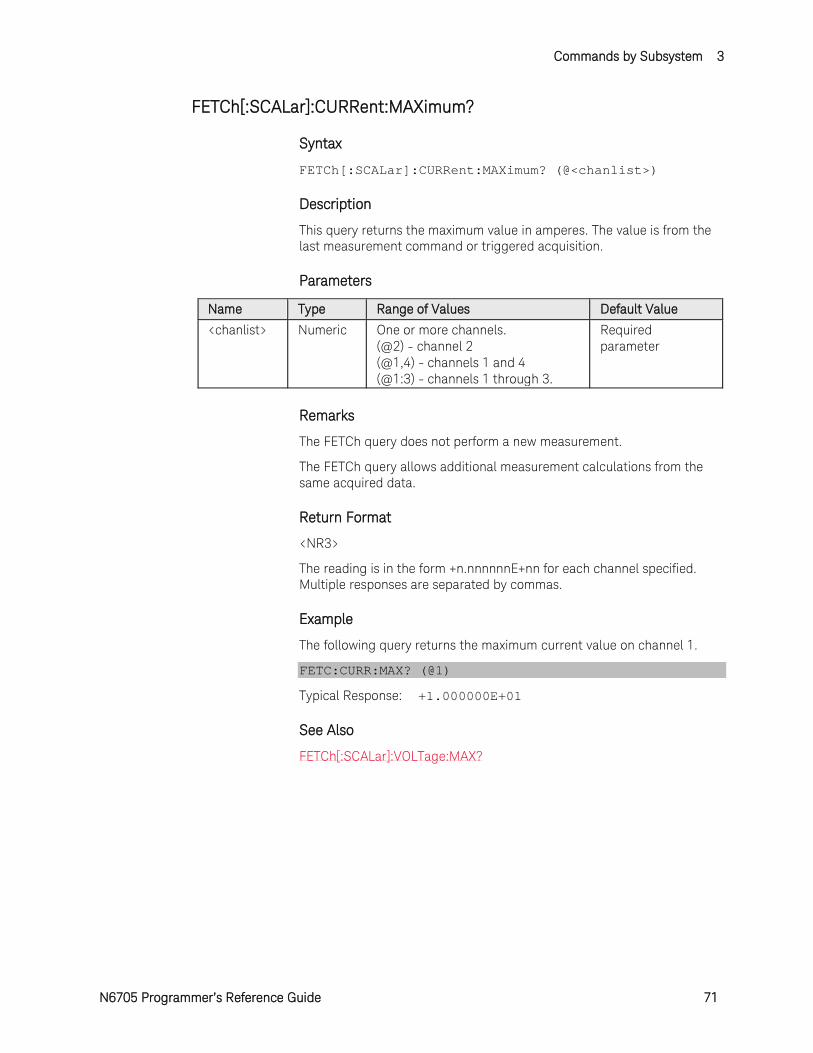
Commands by Subsystem 3
N6705 Programmer’s Reference Guide 71
FETCh[:SCALar]:CURRent:MAXimum?
Syntax
FETCh[:SCALar]:CURRent:MAXimum? (@<chanlist>)
Description
This query returns the maximum value in amperes. The value is from the last measurement command or triggered acquisition.
Parameters
Name Type Range of Values Default Value <chanlist> Numeric One or more channels.
(@2) - channel 2 (@1,4) - channels 1 and 4 (@1:3) - channels 1 through 3.
Required parameter
Remarks
The FETCh query does not perform a new measurement.
The FETCh query allows additional measurement calculations from the same acquired data.
Return Format
<NR3>
The reading is in the form +n.nnnnnnE+nn for each channel specified. Multiple responses are separated by commas.
Example
The following query returns the maximum current value on channel 1.
FETC:CURR:MAX? (@1)
Typical Response: +1.000000E+01
See Also
FETCh[:SCALar]:VOLTage:MAX?
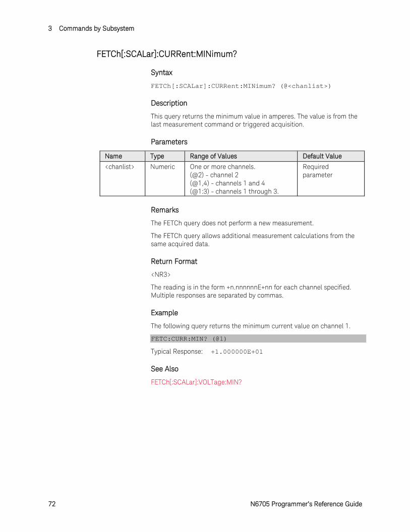
3 Commands by Subsystem
72 N6705 Programmer’s Reference Guide
FETCh[:SCALar]:CURRent:MINimum?
Syntax
FETCh[:SCALar]:CURRent:MINimum? (@<chanlist>)
Description
This query returns the minimum value in amperes. The value is from the last measurement command or triggered acquisition.
Parameters
Name Type Range of Values Default Value <chanlist> Numeric One or more channels.
(@2) - channel 2 (@1,4) - channels 1 and 4 (@1:3) - channels 1 through 3.
Required parameter
Remarks
The FETCh query does not perform a new measurement.
The FETCh query allows additional measurement calculations from the same acquired data.
Return Format
<NR3>
The reading is in the form +n.nnnnnnE+nn for each channel specified. Multiple responses are separated by commas.
Example
The following query returns the minimum current value on channel 1.
FETC:CURR:MIN? (@1)
Typical Response: +1.000000E+01
See Also
FETCh[:SCALar]:VOLTage:MIN?
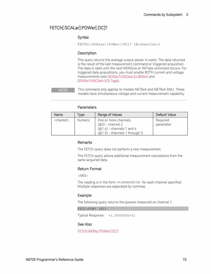
Commands by Subsystem 3
N6705 Programmer’s Reference Guide 73
FETCh[:SCALar]:POWer[:DC]?
Syntax
FETCh[:SCALar]:POWer[:DC]? (@<chanlist>)
Description
This query returns the average output power in watts. The data returned is the result of the last measurement command or triggered acquisition. The data is valid until the next MEASure or INITiate command occurs. For triggered data acquisitions, you must enable BOTH current and voltage measurements (see SENSe:FUNCtion:CURRent and SENSe:FUNCtion:VOLTage).
NOTE This command only applies to models N676xA and N678xA SMU. These models have simultaneous voltage and current measurement capability.
Parameters
Name Type Range of Values Default Value <chanlist> Numeric One or more channels.
(@2) - channel 2 (@1,4) - channels 1 and 4 (@1:3) - channels 1 through 3.
Required parameter
Remarks
The FETCh query does not perform a new measurement.
The FETCh query allows additional measurement calculations from the same acquired data.
Return Format
<NR3>
The reading is in the form +n.nnnnnnE+nn for each channel specified. Multiple responses are separated by commas.
Example
The following query returns the powere measured on channel 1.
FETC:POW? (@1)
Typical Response: +1.000000E+01
See Also
FETCh:ARRay:POWer[:DC]?
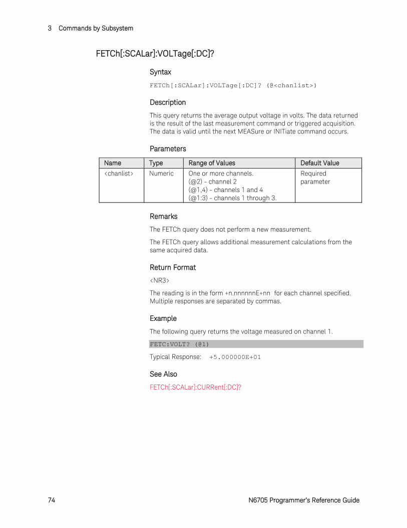
3 Commands by Subsystem
74 N6705 Programmer’s Reference Guide
FETCh[:SCALar]:VOLTage[:DC]?
Syntax
FETCh[:SCALar]:VOLTage[:DC]? (@<chanlist>)
Description
This query returns the average output voltage in volts. The data returned is the result of the last measurement command or triggered acquisition. The data is valid until the next MEASure or INITiate command occurs.
Parameters
Name Type Range of Values Default Value <chanlist> Numeric One or more channels.
(@2) - channel 2 (@1,4) - channels 1 and 4 (@1:3) - channels 1 through 3.
Required parameter
Remarks
The FETCh query does not perform a new measurement.
The FETCh query allows additional measurement calculations from the same acquired data.
Return Format
<NR3>
The reading is in the form +n.nnnnnnE+nn for each channel specified. Multiple responses are separated by commas.
Example
The following query returns the voltage measured on channel 1.
FETC:VOLT? (@1)
Typical Response: +5.000000E+01
See Also
FETCh[:SCALar]:CURRent[:DC]?
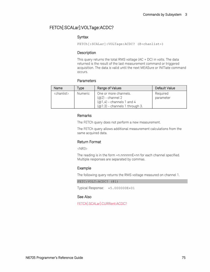
Commands by Subsystem 3
N6705 Programmer’s Reference Guide 75
FETCh[:SCALar]:VOLTage:ACDC?
Syntax
FETCh[:SCALar]:VOLTage:ACDC? (@<chanlist>)
Description
This query returns the total RMS voltage (AC + DC) in volts. The data returned is the result of the last measurement command or triggered acquisition. The data is valid until the next MEASure or INITiate command occurs.
Parameters
Name Type Range of Values Default Value <chanlist> Numeric One or more channels.
(@2) - channel 2 (@1,4) - channels 1 and 4 (@1:3) - channels 1 through 3.
Required parameter
Remarks
The FETCh query does not perform a new measurement.
The FETCh query allows additional measurement calculations from the same acquired data.
Return Format
<NR3>
The reading is in the form +n.nnnnnnE+nn for each channel specified. Multiple responses are separated by commas.
Example
The following query returns the RMS voltage measured on channel 1.
FETC:VOLT:ACDC? (@1)
Typical Response: +5.000000E+01
See Also
FETCh[:SCALar]:CURRent:ACDC?
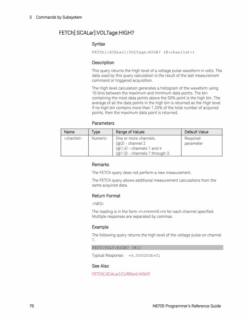
3 Commands by Subsystem
76 N6705 Programmer’s Reference Guide
FETCh[:SCALar]:VOLTage:HIGH?
Syntax
FETCh[:SCALar]:VOLTage:HIGH? (@<chanlist>)
Description
This query returns the High level of a voltage pulse waveform in volts. The data used by this query calculation is the result of the last measurement command or triggered acquisition.
The High level calculation generates a histogram of the waveform using 16 bins between the maximum and minimum data points. The bin containing the most data points above the 50% point is the high bin. The average of all the data points in the high bin is returned as the High level. If no high bin contains more than 1.25% of the total number of acquired points, then the maximum data point is returned.
Parameters
Name Type Range of Values Default Value <chanlist> Numeric One or more channels.
(@2) - channel 2 (@1,4) - channels 1 and 4 (@1:3) - channels 1 through 3.
Required parameter
Remarks
The FETCh query does not perform a new measurement.
The FETCh query allows additional measurement calculations from the same acquired data.
Return Format
<NR3>
The reading is in the form +n.nnnnnnE+nn for each channel specified. Multiple responses are separated by commas.
Example
The following query returns the high level of the voltage pulse on channel 1.
FETC:VOLT:HIGH? (@1)
Typical Response: +5.000000E+01
See Also
FETCh[:SCALar]:CURRent:HIGH?
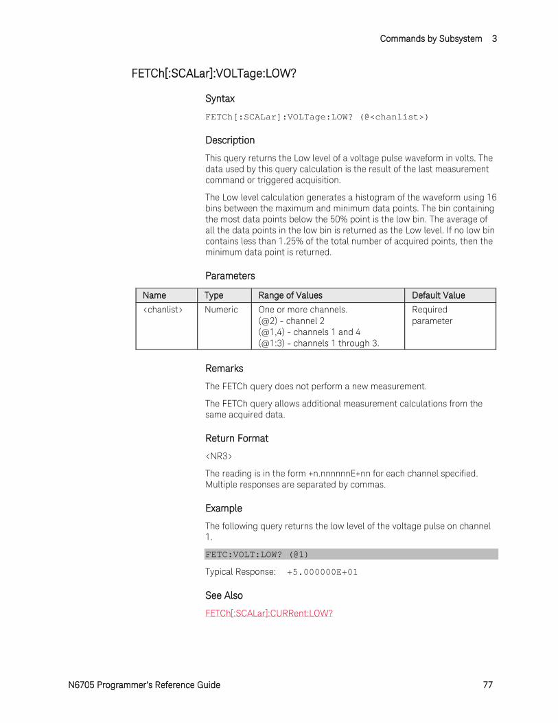
Commands by Subsystem 3
N6705 Programmer’s Reference Guide 77
FETCh[:SCALar]:VOLTage:LOW?
Syntax
FETCh[:SCALar]:VOLTage:LOW? (@<chanlist>)
Description
This query returns the Low level of a voltage pulse waveform in volts. The data used by this query calculation is the result of the last measurement command or triggered acquisition.
The Low level calculation generates a histogram of the waveform using 16 bins between the maximum and minimum data points. The bin containing the most data points below the 50% point is the low bin. The average of all the data points in the low bin is returned as the Low level. If no low bin contains less than 1.25% of the total number of acquired points, then the minimum data point is returned.
Parameters
Name Type Range of Values Default Value <chanlist> Numeric One or more channels.
(@2) - channel 2 (@1,4) - channels 1 and 4 (@1:3) - channels 1 through 3.
Required parameter
Remarks
The FETCh query does not perform a new measurement.
The FETCh query allows additional measurement calculations from the same acquired data.
Return Format
<NR3>
The reading is in the form +n.nnnnnnE+nn for each channel specified. Multiple responses are separated by commas.
Example
The following query returns the low level of the voltage pulse on channel 1.
FETC:VOLT:LOW? (@1)
Typical Response: +5.000000E+01
See Also
FETCh[:SCALar]:CURRent:LOW?
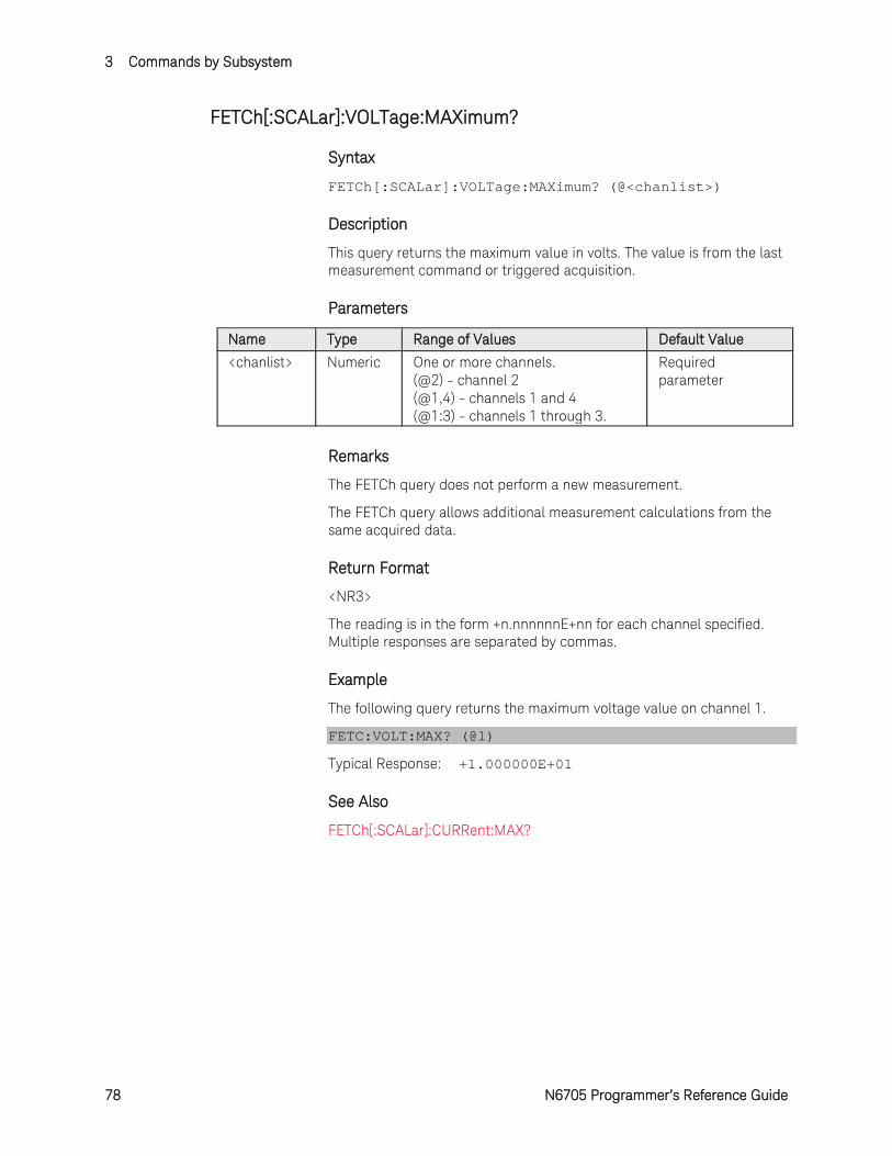
3 Commands by Subsystem
78 N6705 Programmer’s Reference Guide
FETCh[:SCALar]:VOLTage:MAXimum?
Syntax
FETCh[:SCALar]:VOLTage:MAXimum? (@<chanlist>)
Description
This query returns the maximum value in volts. The value is from the last measurement command or triggered acquisition.
Parameters
Name Type Range of Values Default Value <chanlist> Numeric One or more channels.
(@2) - channel 2 (@1,4) - channels 1 and 4 (@1:3) - channels 1 through 3.
Required parameter
Remarks
The FETCh query does not perform a new measurement.
The FETCh query allows additional measurement calculations from the same acquired data.
Return Format
<NR3>
The reading is in the form +n.nnnnnnE+nn for each channel specified. Multiple responses are separated by commas.
Example
The following query returns the maximum voltage value on channel 1.
FETC:VOLT:MAX? (@1)
Typical Response: +1.000000E+01
See Also
FETCh[:SCALar]:CURRent:MAX?
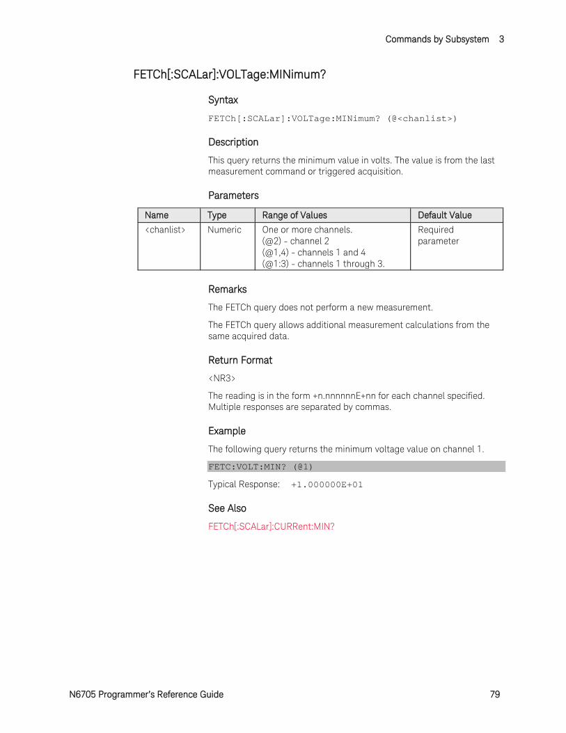
Commands by Subsystem 3
N6705 Programmer’s Reference Guide 79
FETCh[:SCALar]:VOLTage:MINimum?
Syntax
FETCh[:SCALar]:VOLTage:MINimum? (@<chanlist>)
Description
This query returns the minimum value in volts. The value is from the last measurement command or triggered acquisition.
Parameters
Name Type Range of Values Default Value <chanlist> Numeric One or more channels.
(@2) - channel 2 (@1,4) - channels 1 and 4 (@1:3) - channels 1 through 3.
Required parameter
Remarks
The FETCh query does not perform a new measurement.
The FETCh query allows additional measurement calculations from the same acquired data.
Return Format
<NR3>
The reading is in the form +n.nnnnnnE+nn for each channel specified. Multiple responses are separated by commas.
Example
The following query returns the minimum voltage value on channel 1.
FETC:VOLT:MIN? (@1)
Typical Response: +1.000000E+01
See Also
FETCh[:SCALar]:CURRent:MIN?
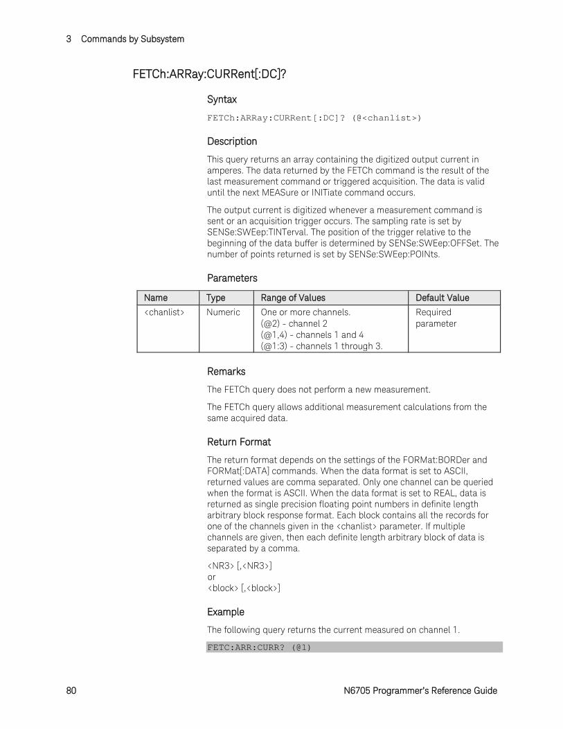
3 Commands by Subsystem
80 N6705 Programmer’s Reference Guide
FETCh:ARRay:CURRent[:DC]?
Syntax
FETCh:ARRay:CURRent[:DC]? (@<chanlist>)
Description
This query returns an array containing the digitized output current in amperes. The data returned by the FETCh command is the result of the last measurement command or triggered acquisition. The data is valid until the next MEASure or INITiate command occurs.
The output current is digitized whenever a measurement command is sent or an acquisition trigger occurs. The sampling rate is set by SENSe:SWEep:TINTerval. The position of the trigger relative to the beginning of the data buffer is determined by SENSe:SWEep:OFFSet. The number of points returned is set by SENSe:SWEep:POINts.
Parameters
Name Type Range of Values Default Value <chanlist> Numeric One or more channels.
(@2) - channel 2 (@1,4) - channels 1 and 4 (@1:3) - channels 1 through 3.
Required parameter
Remarks
The FETCh query does not perform a new measurement.
The FETCh query allows additional measurement calculations from the same acquired data.
Return Format
The return format depends on the settings of the FORMat:BORDer and FORMat[:DATA] commands. When the data format is set to ASCII, returned values are comma separated. Only one channel can be queried when the format is ASCII. When the data format is set to REAL, data is returned as single precision floating point numbers in definite length arbitrary block response format. Each block contains all the records for one of the channels given in the <chanlist> parameter. If multiple channels are given, then each definite length arbitrary block of data is separated by a comma.
<NR3> [,<NR3>] or <block> [,<block>]
Example
The following query returns the current measured on channel 1.
FETC:ARR:CURR? (@1)

Commands by Subsystem 3
N6705 Programmer’s Reference Guide 81
See Also
FETCh:ARRay:VOLTage[:DC]?
SENSe:SWEep:TINTerval
SENSe:SWEep:OFFset:POINts
SENSe:SWEep:POINts
FORMat:BORDer
FORMat:[:DATA]
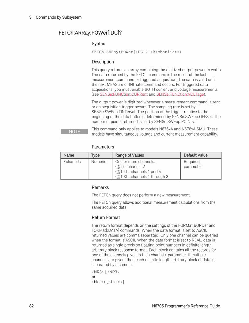
3 Commands by Subsystem
82 N6705 Programmer’s Reference Guide
FETCh:ARRay:POWer[:DC]?
Syntax
FETCh:ARRay:POWer[:DC]? (@<chanlist>)
Description
This query returns an array containing the digitized output power in watts. The data returned by the FETCh command is the result of the last measurement command or triggered acquisition. The data is valid until the next MEASure or INITiate command occurs. For triggered data acquisitions, you must enable BOTH current and voltage measurements (see SENSe:FUNCtion:CURRent and SENSe:FUNCtion:VOLTage).
The output power is digitized whenever a measurement command is sent or an acquisition trigger occurs. The sampling rate is set by SENSe:SWEep:TINTerval. The position of the trigger relative to the beginning of the data buffer is determined by SENSe:SWEep:OFFSet. The number of points returned is set by SENSe:SWEep:POINts.
NOTE This command only applies to models N676xA and N678xA SMU. These models have simultaneous voltage and current measurement capability.
Parameters
Name Type Range of Values Default Value <chanlist> Numeric One or more channels.
(@2) - channel 2 (@1,4) - channels 1 and 4 (@1:3) - channels 1 through 3.
Required parameter
Remarks
The FETCh query does not perform a new measurement.
The FETCh query allows additional measurement calculations from the same acquired data.
Return Format
The return format depends on the settings of the FORMat:BORDer and FORMat[:DATA] commands. When the data format is set to ASCII, returned values are comma separated. Only one channel can be queried when the format is ASCII. When the data format is set to REAL, data is returned as single precision floating point numbers in definite length arbitrary block response format. Each block contains all the records for one of the channels given in the <chanlist> parameter. If multiple channels are given, then each definite length arbitrary block of data is separated by a comma.
<NR3> [,<NR3>] or <block> [,<block>]
Commands by Subsystem 3
N6705 Programmer’s Reference Guide 83
Example
The following query returns the power measured on channel 1.
FETC:ARR:POW? (@1)
See Also
SENSe:SWEep:TINTerval
SENSe:SWEep:OFFset:POINts
SENSe:SWEep:POINts
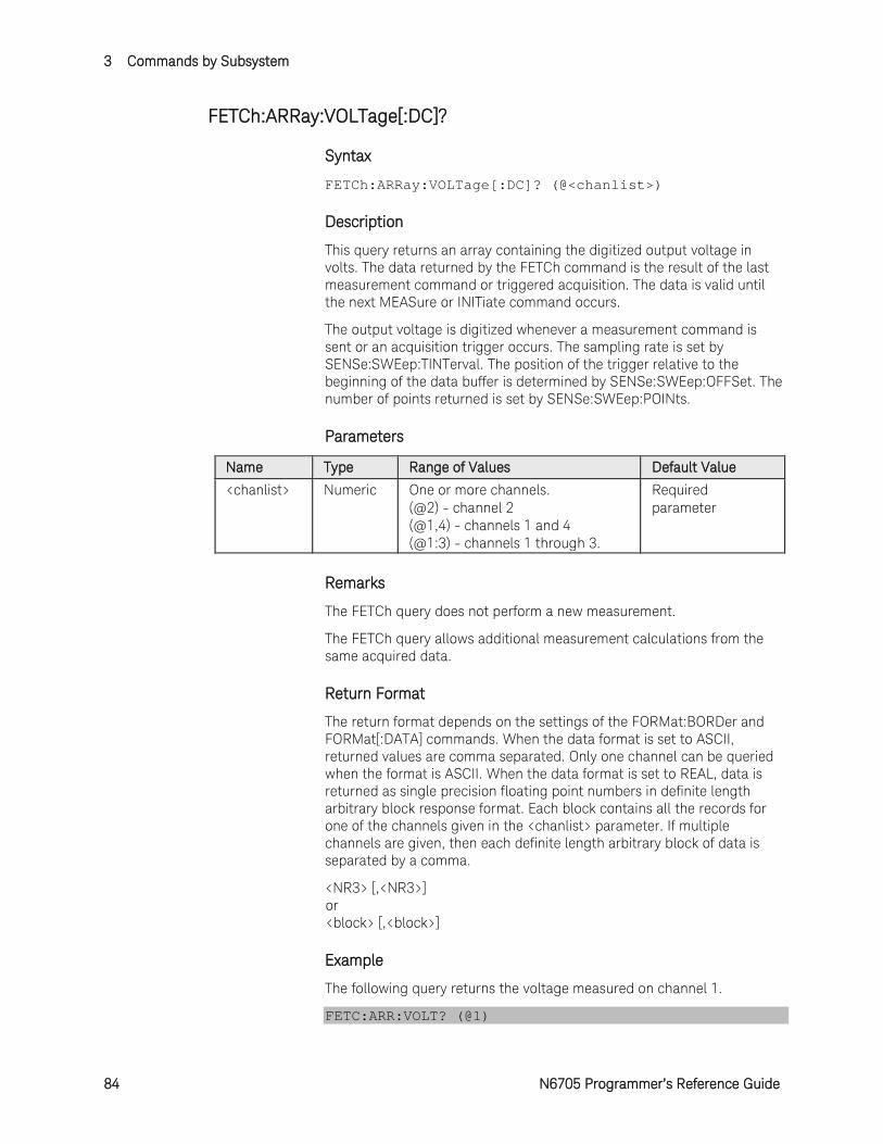
3 Commands by Subsystem
84 N6705 Programmer’s Reference Guide
FETCh:ARRay:VOLTage[:DC]?
Syntax
FETCh:ARRay:VOLTage[:DC]? (@<chanlist>)
Description
This query returns an array containing the digitized output voltage in volts. The data returned by the FETCh command is the result of the last measurement command or triggered acquisition. The data is valid until the next MEASure or INITiate command occurs.
The output voltage is digitized whenever a measurement command is sent or an acquisition trigger occurs. The sampling rate is set by SENSe:SWEep:TINTerval. The position of the trigger relative to the beginning of the data buffer is determined by SENSe:SWEep:OFFSet. The number of points returned is set by SENSe:SWEep:POINts.
Parameters
Name Type Range of Values Default Value <chanlist> Numeric One or more channels.
(@2) - channel 2 (@1,4) - channels 1 and 4 (@1:3) - channels 1 through 3.
Required parameter
Remarks
The FETCh query does not perform a new measurement.
The FETCh query allows additional measurement calculations from the same acquired data.
Return Format
The return format depends on the settings of the FORMat:BORDer and FORMat[:DATA] commands. When the data format is set to ASCII, returned values are comma separated. Only one channel can be queried when the format is ASCII. When the data format is set to REAL, data is returned as single precision floating point numbers in definite length arbitrary block response format. Each block contains all the records for one of the channels given in the <chanlist> parameter. If multiple channels are given, then each definite length arbitrary block of data is separated by a comma.
<NR3> [,<NR3>] or <block> [,<block>]
Example
The following query returns the voltage measured on channel 1.
FETC:ARR:VOLT? (@1)
Commands by Subsystem 3
N6705 Programmer’s Reference Guide 85
See Also
FETCh:ARRay:CURRent[:DC]?
SENSe:SWEep:TINTerval
SENSe:SWEep:OFFset:POINts
SENSe:SWEep:POINts
FORMat:BORDer
FORMat:[:DATA]

3 Commands by Subsystem
86 N6705 Programmer’s Reference Guide
FETCh:DLOG:AHOur?
Syntax
FETCh:DLOG:AHOur? (@<chanlist>)
Description
This query returns the amp-hours delineated by the front panel markers on the selected data log trace that appears in the instrument's Data Logger view. This value corresponds to the Ah (amp-hours) value shown on the bottom of the instrument's Data Logger view when markers are displayed.
Parameters
Name Type Range of Values Default Value <chanlist> Numeric One or more channels.
(@2) - channel 2 (@1,4) - channels 1 and 4 (@1:3) - channels 1 through 3.
Required parameter
Remarks
The value changes when the markers are moved either from the front panel or using the SCPI marker commands.
Return Format
<NR3>
The reading is in the form +n.nnnnnnE+nn for each channel specified. Multiple responses are separated by commas.
Example
The following query returns the amp-hours delineated by the markers on channel 1.
FETC:DLOG:AHO? (@1)
Typical Response: +1.000000E+01
See Also
SENSe:DLOG:MARKer<1,2>:POINt

Commands by Subsystem 3
N6705 Programmer’s Reference Guide 87
FETCh:DLOG:CURRent[:DC]?
Syntax
FETCh:DLOG:CURRent[:DC]? (@<chanlist>)
Description
This query returns the average output current that is delineated by the front panel markers on the selected data log trace that appears in the instrument's Data Logger view. This value corresponds to the Avg (average) value shown on the bottom of the instrument's Data Logger view when markers are displayed.
Parameters
Name Type Range of Values Default Value <chanlist> Numeric One or more channels.
(@2) - channel 2 (@1,4) - channels 1 and 4 (@1:3) - channels 1 through 3.
Required parameter
Remarks
The value changes when the markers are moved either from the front panel or using the SCPI marker commands.
Return Format
<NR3>
The reading is in the form +n.nnnnnnE+nn for each channel specified. Multiple responses are separated by commas.
Example
The following query returns the current delineated by the markers on channel 1.
FETC:DLOG:CURR? (@1)
Typical Response: +1.000000E+01
See Also
SENSe:DLOG:MARKer<1,2>:POINt

3 Commands by Subsystem
88 N6705 Programmer’s Reference Guide
FETCh:DLOG:CURRent:MAXimum?
Syntax
FETCh:DLOG:CURRent:MAXimum? (@<chanlist>)
Description
This query returns the maximum DC output current that is delineated by the front panel markers on the selected data log trace that appears in the instrument's Data Logger view. This value corresponds to the Max value shown on the bottom of the instrument's Data Logger view when markers are displayed.
Parameters
Name Type Range of Values Default Value <chanlist> Numeric One or more channels.
(@2) - channel 2 (@1,4) - channels 1 and 4 (@1:3) - channels 1 through 3.
Required parameter
Remarks
The value changes when the markers are moved either from the front panel or using the SCPI marker commands.
Return Format
<NR3>
The reading is in the form +n.nnnnnnE+nn for each channel specified. Multiple responses are separated by commas.
Example
The following query returns the maximum current delineated by the markers on channel 1.
FETC:DLOG:CURR:MAX? (@1)
Typical Response: +1.000000E+01
See Also
SENSe:DLOG:MARKer<1,2>:POINt
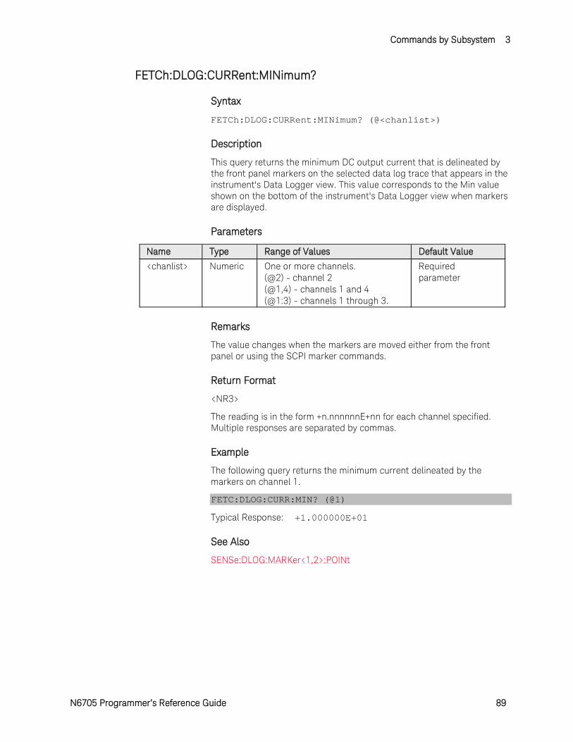
Commands by Subsystem 3
N6705 Programmer’s Reference Guide 89
FETCh:DLOG:CURRent:MINimum?
Syntax
FETCh:DLOG:CURRent:MINimum? (@<chanlist>)
Description
This query returns the minimum DC output current that is delineated by the front panel markers on the selected data log trace that appears in the instrument's Data Logger view. This value corresponds to the Min value shown on the bottom of the instrument's Data Logger view when markers are displayed.
Parameters
Name Type Range of Values Default Value <chanlist> Numeric One or more channels.
(@2) - channel 2 (@1,4) - channels 1 and 4 (@1:3) - channels 1 through 3.
Required parameter
Remarks
The value changes when the markers are moved either from the front panel or using the SCPI marker commands.
Return Format
<NR3>
The reading is in the form +n.nnnnnnE+nn for each channel specified. Multiple responses are separated by commas.
Example
The following query returns the minimum current delineated by the markers on channel 1.
FETC:DLOG:CURR:MIN? (@1)
Typical Response: +1.000000E+01
See Also
SENSe:DLOG:MARKer<1,2>:POINt

3 Commands by Subsystem
90 N6705 Programmer’s Reference Guide
FETCh:DLOG:CURRent:PTPeak?
Syntax
FETCh:DLOG:CURRent:PTPeak? (@<chanlist>)
Description
This query returns the peak-to-peak output current that is delineated by the front panel markers on the selected data log trace that appears in the instrument's Data Logger view. This value corresponds to the Vp-p value shown on the bottom of the instrument's Data Logger view when markers are displayed.
Parameters
Name Type Range of Values Default Value <chanlist> Numeric One or more channels.
(@2) - channel 2 (@1,4) - channels 1 and 4 (@1:3) - channels 1 through 3.
Required parameter
Remarks
The value changes when the markers are moved either from the front panel or using the SCPI marker commands.
Return Format
<NR3>
The reading is in the form +n.nnnnnnE+nn for each channel specified. Multiple responses are separated by commas.
Example
The following query returns the peak-to-peak current delineated by the markers on channel 1.
FETC:DLOG:CURR:PTP? (@1)
Typical Response: +1.000000E+01
See Also
SENSe:DLOG:MARKer<1,2>:POINt

Commands by Subsystem 3
N6705 Programmer’s Reference Guide 91
FETCh:DLOG:VOLTage[:DC]?
Syntax
FETCh:DLOG:VOLTage[:DC]? (@<chanlist>)
Description
This query returns the average output voltage that is delineated by the front panel markers on the selected data log trace that appears in the instrument's Data Logger view. This value corresponds to the Avg (average) value shown on the bottom of the instrument's Data Logger view when markers are displayed.
Parameters
Name Type Range of Values Default Value <chanlist> Numeric One or more channels.
(@2) - channel 2 (@1,4) - channels 1 and 4 (@1:3) - channels 1 through 3.
Required parameter
Remarks
The value changes when the markers are moved either from the front panel or using the SCPI marker commands.
Return Format
<NR3>
The reading is in the form +n.nnnnnnE+nn for each channel specified. Multiple responses are separated by commas.
Example
The following query returns the voltage delineated by the markers on channel 1.
FETC:DLOG:VOLT? (@1)
Typical Response: +1.000000E+01
See Also
SENSe:DLOG:MARKer<1,2>:POINt
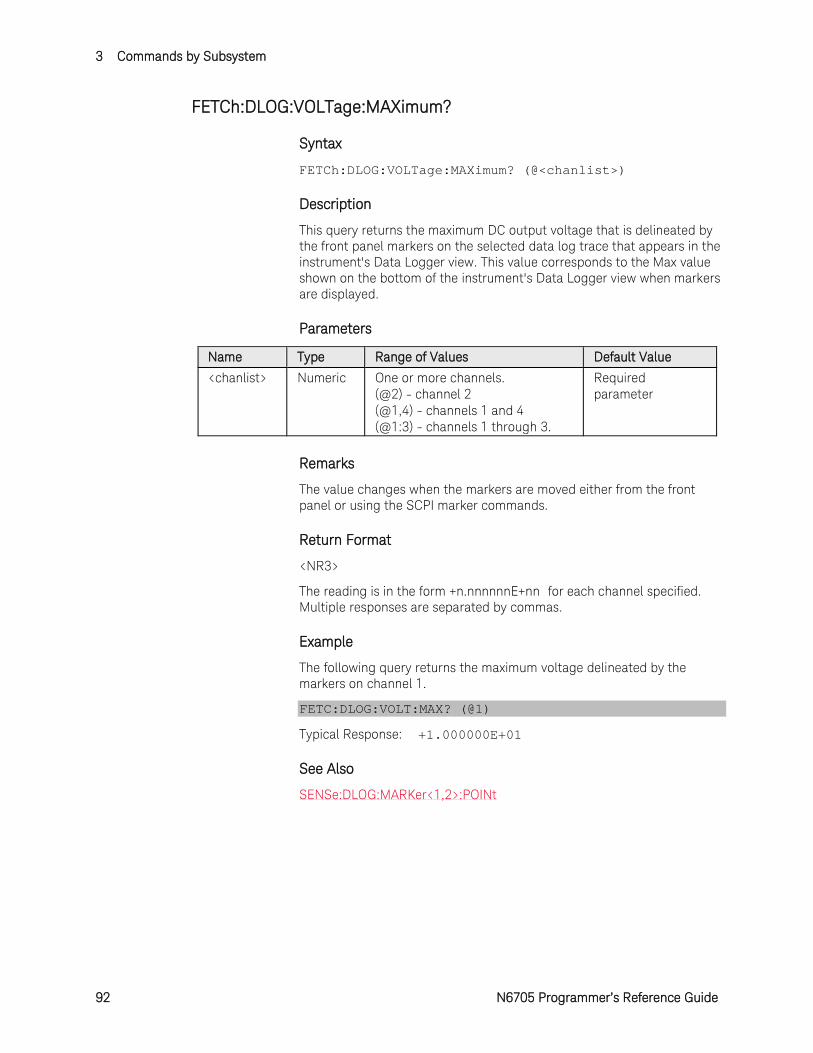
3 Commands by Subsystem
92 N6705 Programmer’s Reference Guide
FETCh:DLOG:VOLTage:MAXimum?
Syntax
FETCh:DLOG:VOLTage:MAXimum? (@<chanlist>)
Description
This query returns the maximum DC output voltage that is delineated by the front panel markers on the selected data log trace that appears in the instrument's Data Logger view. This value corresponds to the Max value shown on the bottom of the instrument's Data Logger view when markers are displayed.
Parameters
Name Type Range of Values Default Value <chanlist> Numeric One or more channels.
(@2) - channel 2 (@1,4) - channels 1 and 4 (@1:3) - channels 1 through 3.
Required parameter
Remarks
The value changes when the markers are moved either from the front panel or using the SCPI marker commands.
Return Format
<NR3>
The reading is in the form +n.nnnnnnE+nn for each channel specified. Multiple responses are separated by commas.
Example
The following query returns the maximum voltage delineated by the markers on channel 1.
FETC:DLOG:VOLT:MAX? (@1)
Typical Response: +1.000000E+01
See Also
SENSe:DLOG:MARKer<1,2>:POINt

Commands by Subsystem 3
N6705 Programmer’s Reference Guide 93
FETCh:DLOG:VOLTage:MINimum?
Syntax
FETCh:DLOG:VOLTage:MINimum? (@<chanlist>)
Description
This query returns the minimum DC output voltage that is delineated by the front panel markers on the selected data log trace that appears in the instrument's Data Logger view. This value corresponds to the Min value shown on the bottom of the instrument's Data Logger view when markers are displayed.
Parameters
Name Type Range of Values Default Value <chanlist> Numeric One or more channels.
(@2) - channel 2 (@1,4) - channels 1 and 4 (@1:3) - channels 1 through 3.
Required parameter
Remarks
The value changes when the markers are moved either from the front panel or using the SCPI marker commands.
Return Format
<NR3>
The reading is in the form +n.nnnnnnE+nn for each channel specified. Multiple responses are separated by commas.
Example
The following query returns the minimum voltage delineated by the markers on channel 1.
FETC:DLOG:VOLT:MIN? (@1)
Typical Response: +1.000000E+01
See Also
SENSe:DLOG:MARKer<1,2>:POINt
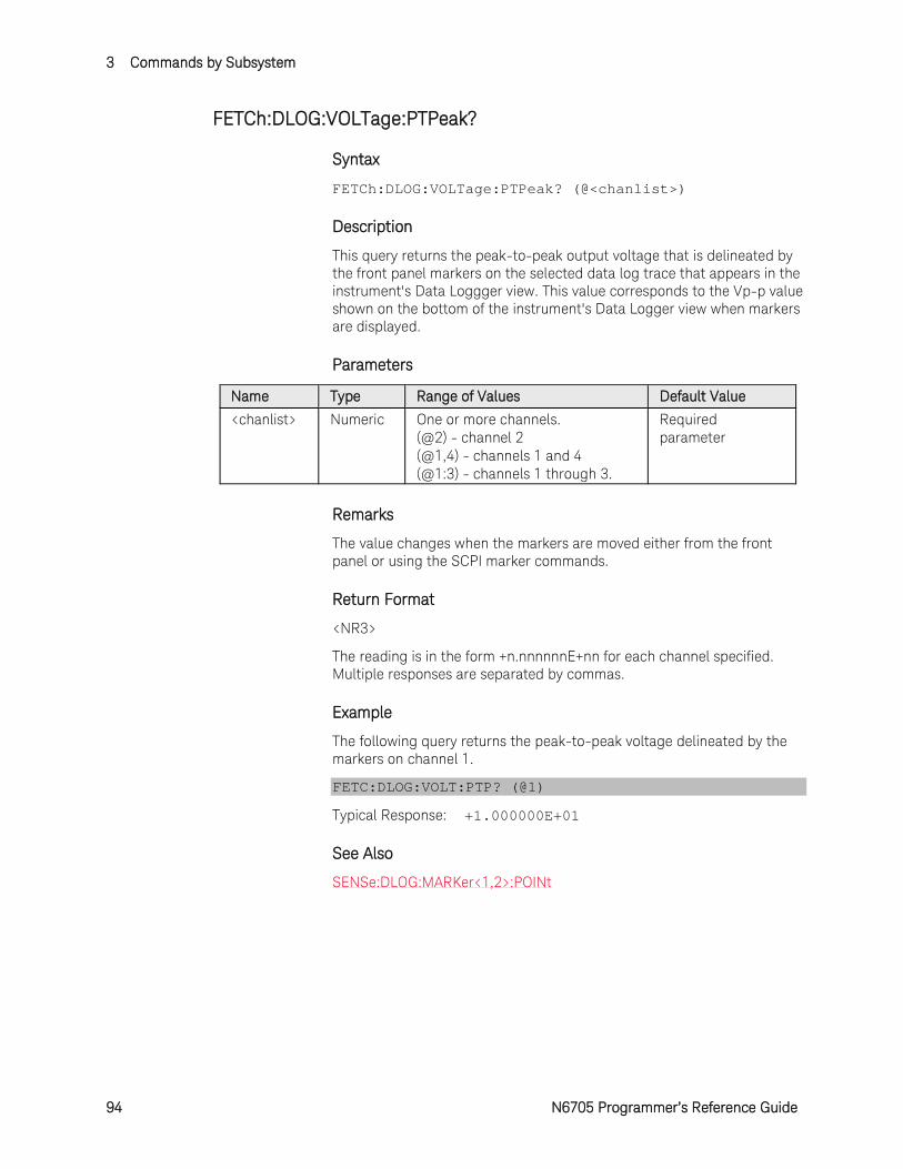
3 Commands by Subsystem
94 N6705 Programmer’s Reference Guide
FETCh:DLOG:VOLTage:PTPeak?
Syntax
FETCh:DLOG:VOLTage:PTPeak? (@<chanlist>)
Description
This query returns the peak-to-peak output voltage that is delineated by the front panel markers on the selected data log trace that appears in the instrument's Data Loggger view. This value corresponds to the Vp-p value shown on the bottom of the instrument's Data Logger view when markers are displayed.
Parameters
Name Type Range of Values Default Value <chanlist> Numeric One or more channels.
(@2) - channel 2 (@1,4) - channels 1 and 4 (@1:3) - channels 1 through 3.
Required parameter
Remarks
The value changes when the markers are moved either from the front panel or using the SCPI marker commands.
Return Format
<NR3>
The reading is in the form +n.nnnnnnE+nn for each channel specified. Multiple responses are separated by commas.
Example
The following query returns the peak-to-peak voltage delineated by the markers on channel 1.
FETC:DLOG:VOLT:PTP? (@1)
Typical Response: +1.000000E+01
See Also
SENSe:DLOG:MARKer<1,2>:POINt
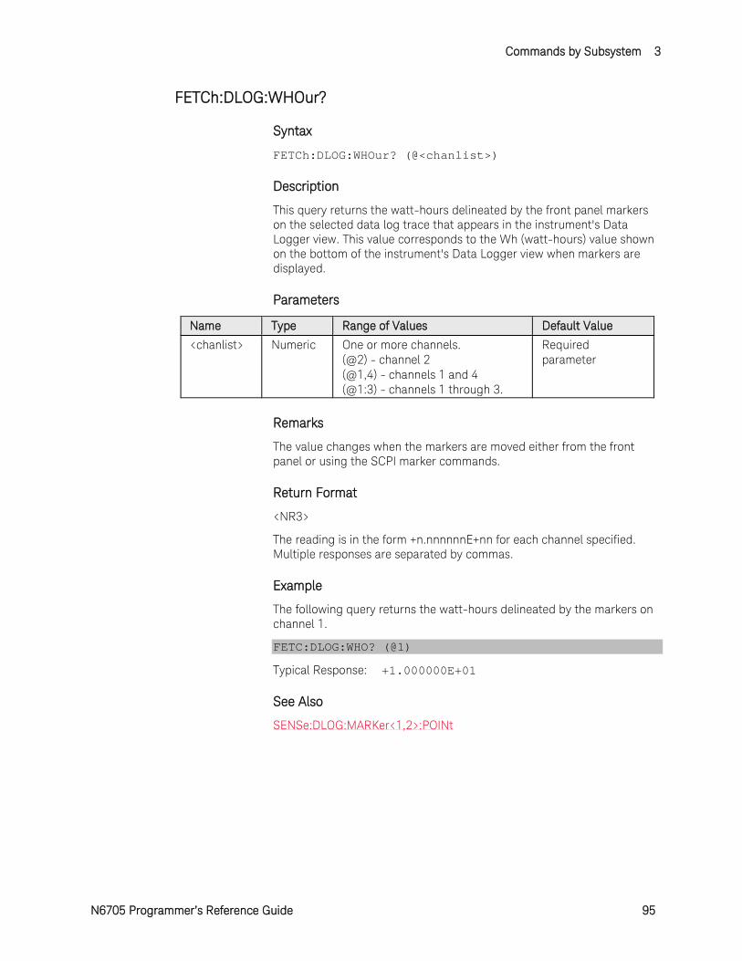
Commands by Subsystem 3
N6705 Programmer’s Reference Guide 95
FETCh:DLOG:WHOur?
Syntax
FETCh:DLOG:WHOur? (@<chanlist>)
Description
This query returns the watt-hours delineated by the front panel markers on the selected data log trace that appears in the instrument's Data Logger view. This value corresponds to the Wh (watt-hours) value shown on the bottom of the instrument's Data Logger view when markers are displayed.
Parameters
Name Type Range of Values Default Value <chanlist> Numeric One or more channels.
(@2) - channel 2 (@1,4) - channels 1 and 4 (@1:3) - channels 1 through 3.
Required parameter
Remarks
The value changes when the markers are moved either from the front panel or using the SCPI marker commands.
Return Format
<NR3>
The reading is in the form +n.nnnnnnE+nn for each channel specified. Multiple responses are separated by commas.
Example
The following query returns the watt-hours delineated by the markers on channel 1.
FETC:DLOG:WHO? (@1)
Typical Response: +1.000000E+01
See Also
SENSe:DLOG:MARKer<1,2>:POINt
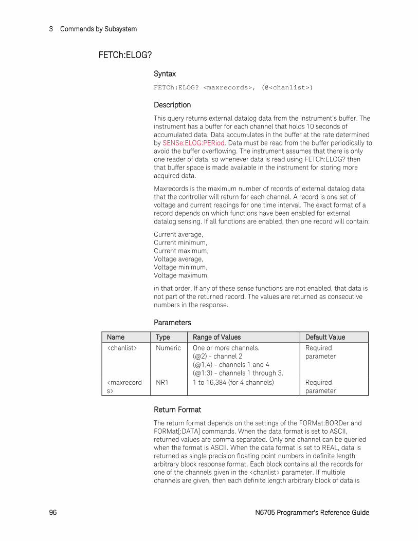
3 Commands by Subsystem
96 N6705 Programmer’s Reference Guide
FETCh:ELOG?
Syntax
FETCh:ELOG? <maxrecords>, (@<chanlist>)
Description
This query returns external datalog data from the instrument’s buffer. The instrument has a buffer for each channel that holds 10 seconds of accumulated data. Data accumulates in the buffer at the rate determined by SENSe:ELOG:PERiod. Data must be read from the buffer periodically to avoid the buffer overflowing. The instrument assumes that there is only one reader of data, so whenever data is read using FETCh:ELOG? then that buffer space is made available in the instrument for storing more acquired data.
Maxrecords is the maximum number of records of external datalog data that the controller will return for each channel. A record is one set of voltage and current readings for one time interval. The exact format of a record depends on which functions have been enabled for external datalog sensing. If all functions are enabled, then one record will contain:
Current average, Current minimum, Current maximum, Voltage average, Voltage minimum, Voltage maximum,
in that order. If any of these sense functions are not enabled, that data is not part of the returned record. The values are returned as consecutive numbers in the response.
Parameters
Name Type Range of Values Default Value <chanlist> Numeric One or more channels.
(@2) - channel 2 (@1,4) - channels 1 and 4 (@1:3) - channels 1 through 3.
Required parameter
<maxrecords>
NR1 1 to 16,384 (for 4 channels) Required parameter
Return Format
The return format depends on the settings of the FORMat:BORDer and FORMat[:DATA] commands. When the data format is set to ASCII, returned values are comma separated. Only one channel can be queried when the format is ASCII. When the data format is set to REAL, data is returned as single precision floating point numbers in definite length arbitrary block response format. Each block contains all the records for one of the channels given in the <chanlist> parameter. If multiple channels are given, then each definite length arbitrary block of data is
Commands by Subsystem 3
N6705 Programmer’s Reference Guide 97
separated by a comma.
<NR3> [,<NR3>] or <block> [,<block>]
Example
The following query returns 100 data records of channel 1.
FETC:ELOG? 100, @1
See Also
FORMat:BORDer
FORMat[:DATA]
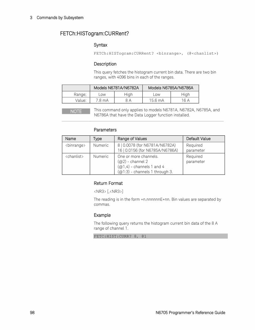
3 Commands by Subsystem
98 N6705 Programmer’s Reference Guide
FETCh:HISTogram:CURRent?
Syntax
FETCh:HISTogram:CURRent? <binrange>, (@<chanlist>)
Description
This query fetches the histogram current bin data. There are two bin ranges, with 4096 bins in each of the ranges.
Models N6781A/N6782A Models N6785A/N6786A Range; Low High Low High Value: 7.8 mA 8 A 15.6 mA 16 A
NOTE This command only applies to models N6781A, N6782A, N6785A, and N6786A that have the Data Logger function installed.
Parameters
Name Type Range of Values Default Value <binrange> Numeric 8 | 0.0078 (for N6781A/N6782A)
16 | 0.0156 (for N6785A/N6786A) Required parameter
<chanlist> Numeric One or more channels. (@2) - channel 2 (@1,4) - channels 1 and 4 (@1:3) - channels 1 through 3.
Required parameter
Return Format
<NR3> [,<NR3>]
The reading is in the form +n.nnnnnnE+nn. Bin values are separated by commas.
Example
The following query returns the histogram current bin data of the 8 A range of channel 1.
FETC:HIST:CURR? 8, @1
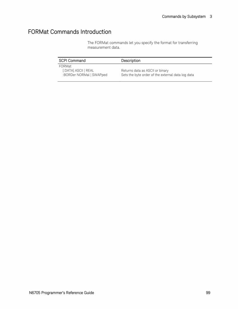
Commands by Subsystem 3
N6705 Programmer’s Reference Guide 99
FORMat Commands Introduction
The FORMat commands let you specify the format for transferring measurement data.
SCPI Command Description FORMat [:DATA] ASCII | REAL Returns data as ASCII or binary :BORDer NORMal | SWAPped Sets the byte order of the external data log data
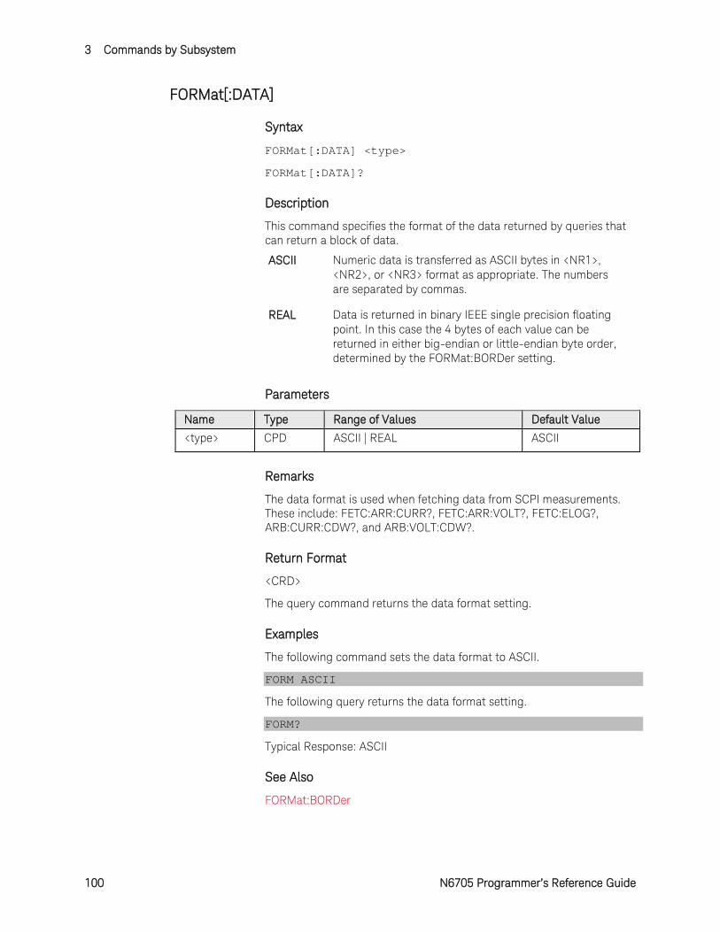
3 Commands by Subsystem
100 N6705 Programmer’s Reference Guide
FORMat[:DATA]
Syntax
FORMat[:DATA] <type>
FORMat[:DATA]?
Description
This command specifies the format of the data returned by queries that can return a block of data.
ASCII Numeric data is transferred as ASCII bytes in <NR1>, <NR2>, or <NR3> format as appropriate. The numbers are separated by commas.
REAL Data is returned in binary IEEE single precision floating point. In this case the 4 bytes of each value can be returned in either big-endian or little-endian byte order, determined by the FORMat:BORDer setting.
Parameters
Name Type Range of Values Default Value
<type> CPD ASCII | REAL ASCII
Remarks
The data format is used when fetching data from SCPI measurements. These include: FETC:ARR:CURR?, FETC:ARR:VOLT?, FETC:ELOG?, ARB:CURR:CDW?, and ARB:VOLT:CDW?.
Return Format
<CRD>
The query command returns the data format setting.
Examples
The following command sets the data format to ASCII.
FORM ASCII
The following query returns the data format setting.
FORM?
Typical Response: ASCII
See Also
FORMat:BORDer
Commands by Subsystem 3
N6705 Programmer’s Reference Guide 101
FORMat:BORDer
Syntax
FORMat:BORDer <setting>
FORMat:BORDer?
Description
This command specifies how binary data is transferred. This only applies when the FORMat:DATA is set to REAL.
NORMal Binary data is transferred in normal order. The most significant byte is returned first, and the least significant byte is returned last (big-endian).
SWAPped Binary data is transferred in swapped-byte order. The least significant byte is returned first, and the most significant byte is returned last (little-endian).
Parameters
Name Type Range of Values Default Value
<setting> CPD NORMal | SWAPped NORMal
Remarks
The byte order is used when fetching data from SCPI measurements. These include: FETC:ARR:CURR?, FETC:ARR:VOLT?, FETC:ELOG?, ARB:CURR:CDW?, and ARB:VOLT:CDW?.
Return Format
<CRD>
The query command returns the binary byte order setting.
Examples
The following command sets the byte order setting to SWAPped.
FORM:BORD SWAP
The following query returns the byte order setting.
FORM:BORD?
Typical Response: SWAP
See Also
FORMat[:DATA]
3 Commands by Subsystem
102 N6705 Programmer’s Reference Guide
HCOPy Commands Introduction
HCOPy commands provide screen shots of the front panel display.
SCPI Command Description HCOPy:SDUMp:DATA? Returns an image of the display in .gif format
Commands by Subsystem 3
N6705 Programmer’s Reference Guide 103
HCOPy:SDUMp:DATA?
Syntax
HCOPy:SDUMp:DATA?
Description
This query returns the front panel LCD image formatted as a compressed GIF (graphical image file). The size of the compressed image is approximately 5k bytes.
Return Format
<Block>
The response is an indefinite length arbitrary binary block of the form:
#0<data-bytes>NL^END
#0 indicates the response is an indefinite length. The end of the block is a newline with EOI asserted.
Example
The following query returns the LCD image.
HCOP:SDUM:DATA?
3 Commands by Subsystem
104 N6705 Programmer’s Reference Guide
INITiate Subsystem Introduction
Initiate commands initialize the trigger system. This enables the trigger system to receive triggers.
SCPI Command Description INITiate [:IMMediate] :ACQuire (@chanlist) Enables measurement triggers :DLOG <“filename”> Enables the data logger function :ELOG (@chanlist) Enables external data logger measurements :HISTogram (@chanlist) Enables histogram measurements (N6781A, N6782A, N6785A, and
N6786A) :TRANsient (@chanlist) Enables output triggers :CONTinuous :TRANsient <Bool>, (@chanlist)
Enables/disables continuous transient triggers
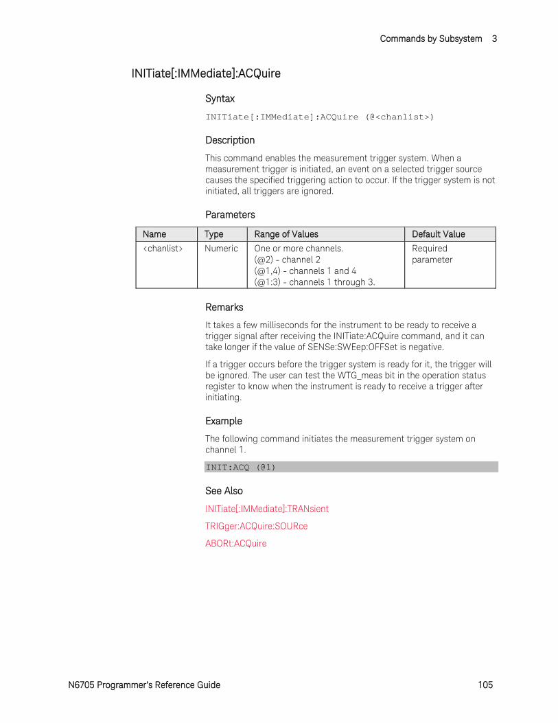
Commands by Subsystem 3
N6705 Programmer’s Reference Guide 105
INITiate[:IMMediate]:ACQuire
Syntax
INITiate[:IMMediate]:ACQuire (@<chanlist>)
Description
This command enables the measurement trigger system. When a measurement trigger is initiated, an event on a selected trigger source causes the specified triggering action to occur. If the trigger system is not initiated, all triggers are ignored.
Parameters
Name Type Range of Values Default Value
<chanlist> Numeric One or more channels. (@2) - channel 2 (@1,4) - channels 1 and 4 (@1:3) - channels 1 through 3.
Required parameter
Remarks
It takes a few milliseconds for the instrument to be ready to receive a trigger signal after receiving the INITiate:ACQuire command, and it can take longer if the value of SENSe:SWEep:OFFSet is negative.
If a trigger occurs before the trigger system is ready for it, the trigger will be ignored. The user can test the WTG_meas bit in the operation status register to know when the instrument is ready to receive a trigger after initiating.
Example
The following command initiates the measurement trigger system on channel 1.
INIT:ACQ (@1)
See Also
INITiate[:IMMediate]:TRANsient
TRIGger:ACQuire:SOURce
ABORt:ACQuire
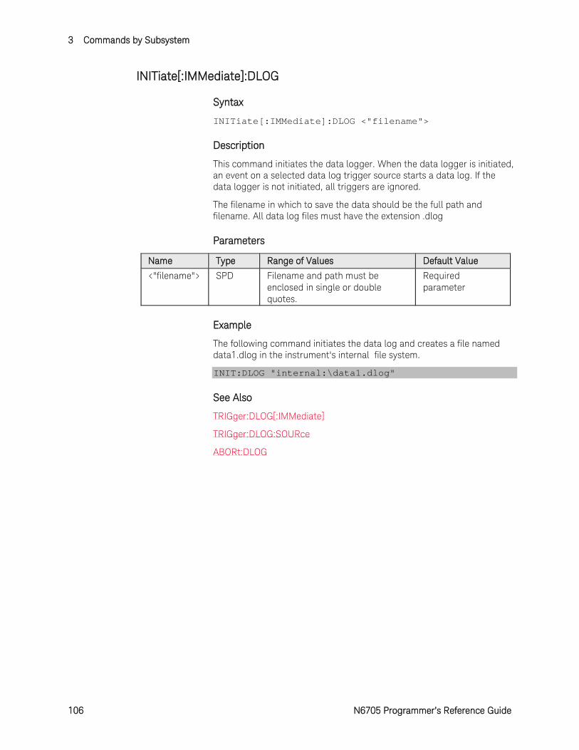
3 Commands by Subsystem
106 N6705 Programmer’s Reference Guide
INITiate[:IMMediate]:DLOG
Syntax
INITiate[:IMMediate]:DLOG <"filename">
Description
This command initiates the data logger. When the data logger is initiated, an event on a selected data log trigger source starts a data log. If the data logger is not initiated, all triggers are ignored.
The filename in which to save the data should be the full path and filename. All data log files must have the extension .dlog
Parameters
Name Type Range of Values Default Value <"filename"> SPD Filename and path must be
enclosed in single or double quotes.
Required parameter
Example
The following command initiates the data log and creates a file named data1.dlog in the instrument's internal file system.
INIT:DLOG "internal:\data1.dlog"
See Also
TRIGger:DLOG[:IMMediate]
TRIGger:DLOG:SOURce
ABORt:DLOG
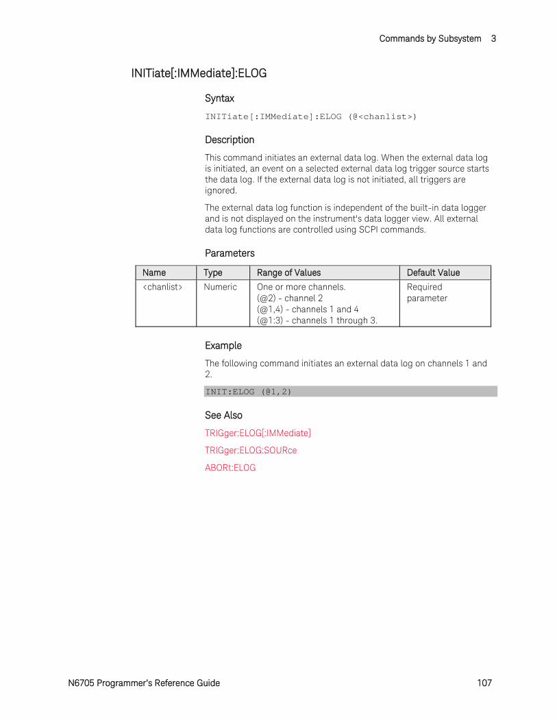
Commands by Subsystem 3
N6705 Programmer’s Reference Guide 107
INITiate[:IMMediate]:ELOG
Syntax
INITiate[:IMMediate]:ELOG (@<chanlist>)
Description
This command initiates an external data log. When the external data log is initiated, an event on a selected external data log trigger source starts the data log. If the external data log is not initiated, all triggers are ignored.
The external data log function is independent of the built-in data logger and is not displayed on the instrument's data logger view. All external data log functions are controlled using SCPI commands.
Parameters
Name Type Range of Values Default Value <chanlist> Numeric One or more channels.
(@2) - channel 2 (@1,4) - channels 1 and 4 (@1:3) - channels 1 through 3.
Required parameter
Example
The following command initiates an external data log on channels 1 and 2.
INIT:ELOG (@1,2)
See Also
TRIGger:ELOG[:IMMediate]
TRIGger:ELOG:SOURce
ABORt:ELOG
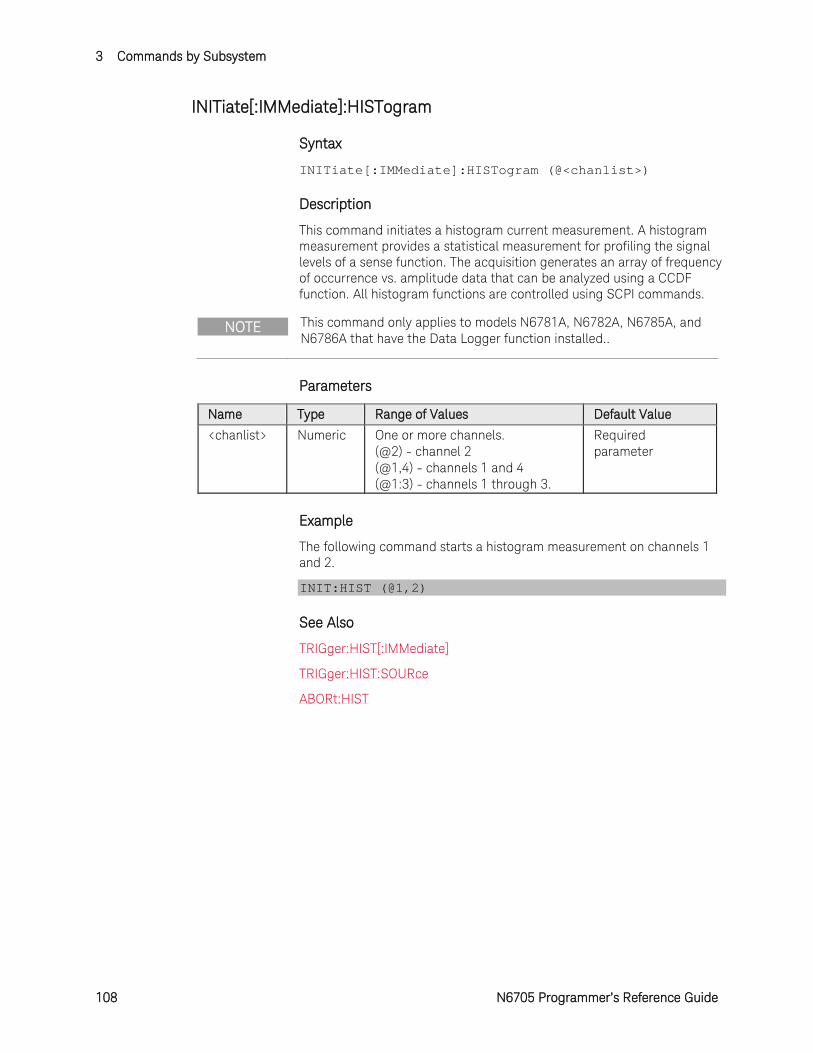
3 Commands by Subsystem
108 N6705 Programmer’s Reference Guide
INITiate[:IMMediate]:HISTogram
Syntax
INITiate[:IMMediate]:HISTogram (@<chanlist>)
Description
This command initiates a histogram current measurement. A histogram measurement provides a statistical measurement for profiling the signal levels of a sense function. The acquisition generates an array of frequency of occurrence vs. amplitude data that can be analyzed using a CCDF function. All histogram functions are controlled using SCPI commands.
NOTE This command only applies to models N6781A, N6782A, N6785A, and N6786A that have the Data Logger function installed..
Parameters
Name Type Range of Values Default Value <chanlist> Numeric One or more channels.
(@2) - channel 2 (@1,4) - channels 1 and 4 (@1:3) - channels 1 through 3.
Required parameter
Example
The following command starts a histogram measurement on channels 1 and 2.
INIT:HIST (@1,2)
See Also
TRIGger:HIST[:IMMediate]
TRIGger:HIST:SOURce
ABORt:HIST
Commands by Subsystem 3
N6705 Programmer’s Reference Guide 109
INITiate[:IMMediate]:TRANsient
Syntax
INITiate[:IMMediate]:TRANsient (@<chanlist>)
Description
This command enables the output trigger system. When an output trigger is initiated, an event on a selected trigger source causes the specified triggering action to occur. If the trigger system is not initiated, all triggers are ignored.
Parameters
Name Type Range of Values Default Value
<chanlist> Numeric One or more channels. (@2) - channel 2 (@1,4) - channels 1 and 4 (@1:3) - channels 1 through 3.
Required parameter
Example
The following command initiates the transient trigger system on channel 1.
INIT:TRAN (@1)
See Also
INITiate[:IMMediate]:ACQuire
ABORt:TRANsient
3 Commands by Subsystem
110 N6705 Programmer’s Reference Guide
INITiate:CONTinuous:TRANsient
Syntax
INITiate:CONTinuous:TRANsient <Bool>, (@<chanlist>)
INITiate:CONTinuous:TRANsient? (@<chanlist>)
Description
This command continuously initiates the output trigger system. This allows multiple triggers to generate multiple output transients with no intermediate commands. The enabled state is ON (1); the disabled state is OFF (0).
NOTE With continuous triggering disabled, the output trigger system must be initiated for each trigger using the INITiate:TRANsient command.
Parameters
Name Type Range of Values Default Value
<Bool> Boolean OFF | 0 | ON | 1 OFF
<chanlist> Numeric One or more channels. (@2) - channel 2 (@1,4) - channels 1 and 4 (@1:3) - channels 1 through 3.
Required parameter
Return Format
<NR1>
The query command returns 0 if continuous transients are disabled (OFF), and 1 if continuous transients are enabled (ON).
Example
The following command continually initiates the transient trigger system on channel 1.
INIT:CONT:TRAN ON,(@1)
The following query returns the continuous transient trigger state.
INIT:CONT:TRAN? (@1)
Typical Response: 0
See Also
INITiate[:IMMediate]:TRANsient
ABORt:TRANsient
Commands by Subsystem 3
N6705 Programmer’s Reference Guide 111
MEASure Subsystem Introduction
Measure commands measure the output voltage or current. They trigger the acquisition of new data before returning the reading. Measurements are performed by digitizing the instantaneous output voltage or current for a specified measurement time, storing the results in a buffer, and calculating the average value. Use Measure commands when the measurement does not need to be synchronized with any other event.
SCPI Command Description MEASure [:SCALar] :CURRent [:DC]? (@chanlist) Takes a measurement; returns the average current :ACDC? (@chanlist) Takes a measurement; returns the total rms current (AC + DC) :HIGH? (@chanlist) Takes a measurement; returns the high level of a current pulse :LOW? (@chanlist) Takes a measurement; returns the low level of a current pulse :MAXimum? (@chanlist) Takes a measurement, returns the maximum current :MINimum? (@chanlist) Takes a measurement, returns the minimum current :POWer [:DC]? (@chanlist) Takes a measurement; returns the average output power :VOLTage [:DC]? (@chanlist) Takes a measurement; returns the average voltage :ACDC? (@chanlist) Takes a measurement; returns the total rms voltage (AC + DC) :HIGH? (@chanlist) Takes a measurement; returns the high level of a voltage pulse :LOW? (@chanlist) Takes a measurement; returns the low level of a voltage pulse :MAXimum? (@chanlist) Takes a measurement, returns the maximum voltage :MINimum? (@chanlist) Takes a measurement, returns the minimum voltage :ARRay (Array commands only on N676xA, N678xA SMU and Option
054) :CURRent [:DC]? (@chanlist) Takes a measurement; returns the instantaneous output
current :POWer [:DC]? (@chanlist) Takes a measurement, returns the instantaneous output power :VOLTage [:DC]? (@chanlist) Takes a measurement; returns the instantaneous output
voltage

3 Commands by Subsystem
112 N6705 Programmer’s Reference Guide
MEASure[:SCALar]:CURRent[:DC]?
Syntax
MEASure[:SCALar]:CURRent[:DC]? (@<chanlist>)
Description
This query initiates and triggers a measurement, and returns the average output current in amperes.
Parameters
Name Type Range of Values Default Value
<chanlist> Numeric One or more channels. (@2) - channel 2 (@1,4) - channels 1 and 4 (@1:3) - channels 1 through 3.
Required parameter
Remarks
The MEASure query starts a new measurement immediately. It is not synchronized to any trigger event.
Use the INITiate, trigger, and FETCh sequence if a synchronized measurement is necessary.
The default time interval and number of points settings yield a measurement time of 21 milliseconds per reading (1024 data points at 20.48 microsecond intervals). The default windowing function is Rectangular.
Return Format
<NR3>
The reading is in the form +n.nnnnnnE+nn for each channel specified. Multiple responses are separated by commas.
Example
The following query returns the current measured on channel 1.
MEAS:CURR? (@1)
Typical Response: +1.000000E+01
See Also
MEASure[:SCALar]:VOLTage[:DC]?
Commands by Subsystem 3
N6705 Programmer’s Reference Guide 113
MEASure[:SCALar]:CURRent:ACDC?
Syntax
MEASure[:SCALar]:CURRent:ACDC? (@<chanlist>)
Description
This query initiates and triggers a measurement, and returns the total RMS current (AC + DC) in amperes.
Parameters
Name Type Range of Values Default Value
<chanlist> Numeric One or more channels. (@2) - channel 2 (@1,4) - channels 1 and 4 (@1:3) - channels 1 through 3.
Required parameter
Remarks
The MEASure query starts a new measurement immediately. It is not synchronized to any trigger event.
Use the INITiate, trigger, and FETCh sequence if a synchronized measurement is necessary.
The default time interval and number of points settings yield a measurement time of 21 milliseconds per reading (1024 data points at 20.48 microsecond intervals). The default windowing function is Rectangular.
<NR3>
The reading is in the form +n.nnnnnnE+nn for each channel specified. Multiple responses are separated by commas.
Example
The following query returns the RMS current measured on channel 1.
MEAS:CURR:ACDC? (@1)
Typical Response: +1.000000E+01
See Also
MEASure[:SCALar]:VOLTage:ACDC?
3 Commands by Subsystem
114 N6705 Programmer’s Reference Guide
MEASure[:SCALar]:CURRent:HIGH?
Syntax
MEASure[:SCALar]:CURRent:HIGH? (@<chanlist>)
Description
This query initiates and triggers a measurement, and returns the High level of a current pulse waveform in amperes.
The High level calculation generates a histogram of the waveform using 16 bins between the maximum and minimum data points. The bin containing the most data points above the 50% point is the high bin. The average of all the data points in the high bin is returned as the High level. If no high bin contains more than 1.25% of the total number of acquired points, then the maximum data point is returned.
Parameters
Name Type Range of Values Default Value
<chanlist> Numeric One or more channels. (@2) - channel 2 (@1,4) - channels 1 and 4 (@1:3) - channels 1 through 3.
Required parameter
Remarks
The MEASure query starts a new measurement immediately. It is not synchronized to any trigger event.
Use the INITiate, trigger, and FETCh sequence if a synchronized measurement is necessary.
The default time interval and number of points settings yield a measurement time of 21 milliseconds per reading (1024 data points at 20.48 microsecond intervals). The default windowing function is Rectangular.
Return Format
<NR3>
The reading is in the form +n.nnnnnnE+nn for each channel specified. Multiple responses are separated by commas.
Example
The following query returns the high level of a current pulse on channel 1.
MEAS:CURR:HIGH? (@1)
Typical Response: +1.000000E+01

Commands by Subsystem 3
N6705 Programmer’s Reference Guide 115
See Also
MEASure[:SCALar]:VOLTage:HIGH?

3 Commands by Subsystem
116 N6705 Programmer’s Reference Guide
MEASure[:SCALar]:CURRent:LOW?
Syntax
MEASure[:SCALar]:CURRent:LOW? (@<chanlist>)
Description
This query initiates and triggers a measurement, and returns the Low level of a current pulse waveform in amperes.
The Low level calculation generates a histogram of the waveform using 16 bins between the maximum and minimum data points. The bin containing the most data points below the 50% point is the low bin. The average of all the data points in the low bin is returned as the Low level. If no low bin contains less than 1.25% of the total number of acquired points, then the minimum data point is returned.
Parameters
Name Type Range of Values Default Value
<chanlist> Numeric One or more channels. (@2) - channel 2 (@1,4) - channels 1 and 4 (@1:3) - channels 1 through 3.
Required parameter
Remarks
The MEASure query starts a new measurement immediately. It is not synchronized to any trigger event.
Use the INITiate, trigger, and FETCh sequence if a synchronized measurement is necessary.
The default time interval and number of points settings yield a measurement time of 21 milliseconds per reading (1024 data points at 20.48 microsecond intervals). The default windowing function is Rectangular.
Return Format
<NR3>
The reading is in the form +n.nnnnnnE+nn for each channel specified. Multiple responses are separated by commas.
Example
The following query returns the low level of a current pulse on channel 1.
MEAS:CURR:LOW? (@1)
Typical Response: +1.000000E+01
Commands by Subsystem 3
N6705 Programmer’s Reference Guide 117
See Also
MEASure[:SCALar]:VOLTage:LOW?

3 Commands by Subsystem
118 N6705 Programmer’s Reference Guide
MEASure[:SCALar]:CURRent:MAXimum?
Syntax
MEASure[:SCALar]:CURRent:MAXimum? (@<chanlist>)
Description
This query initiates and triggers a measurement, and returns the maximum value in amperes.
Parameters
Name Type Range of Values Default Value
<chanlist> Numeric One or more channels. (@2) - channel 2 (@1,4) - channels 1 and 4 (@1:3) - channels 1 through 3.
Required parameter
Remarks
The MEASure query starts a new measurement immediately. It is not synchronized to any trigger event.
Use the INITiate, trigger, and FETCh sequence if a synchronized measurement is necessary.
The default time interval and number of points settings yield a measurement time of 21 milliseconds per reading (1024 data points at 20.48 microsecond intervals). The default windowing function is Rectangular.
Return Format
<NR3>
The reading is in the form +n.nnnnnnE+nn for each channel specified. Multiple responses are separated by commas.
Example
The following query returns the maximum current value on channel 1.
MEAS:CURR:MAX? (@1)
Typical Response: +1.000000E+01
See Also
MEASure[:SCALar]:VOLTage:MAX?
Commands by Subsystem 3
N6705 Programmer’s Reference Guide 119
MEASure[:SCALar]:CURRent:MINimum?
Syntax
MEASure[:SCALar]:CURRent:MINimum? (@<chanlist>)
Description
This query initiates and triggers a measurement, and returns the minimum value in amperes.
Parameters
Name Type Range of Values Default Value
<chanlist> Numeric One or more channels. (@2) - channel 2 (@1,4) - channels 1 and 4 (@1:3) - channels 1 through 3.
Required parameter
Remarks
The MEASure query starts a new measurement immediately. It is not synchronized to any trigger event.
Use the INITiate, trigger, and FETCh sequence if a synchronized measurement is necessary.
The default time interval and number of points settings yield a measurement time of 21 milliseconds per reading (1024 data points at 20.48 microsecond intervals). The default windowing function is Rectangular.
Return Format
<NR3>
The reading is in the form +n.nnnnnnE+nn for each channel specified. Multiple responses are separated by commas.
Example
The following query returns the minimum current value on channel 1.
MEAS:CURR:MIN? (@1)
Typical Response: +1.000000E+01
See Also
MEASure[:SCALar]:VOLTage:MIN?
3 Commands by Subsystem
120 N6705 Programmer’s Reference Guide
MEASure[:SCALar]:POWer[:DC]?
Syntax
MEASure[:SCALar]:POWer[:DC]? (@<chanlist>)
Description
This query initiates and triggers a measurement, and returns the average output power in watts.
NOTE This command only applies to models N676xA and N678xA SMU. These models have simultaneous voltage and current measurement capability.
Parameters
Name Type Range of Values Default Value
<chanlist> Numeric One or more channels. (@2) - channel 2 (@1,4) - channels 1 and 4 (@1:3) - channels 1 through 3.
Required parameter
Remarks
The MEASure query starts a new measurement immediately. It is not synchronized to any trigger event.
Use the INITiate, trigger, and FETCh sequence if a synchronized measurement is necessary.
The default time interval and number of points settings yield a measurement time of 21 milliseconds per reading (1024 data points at 20.48 microsecond intervals). The default windowing function is Rectangular.
Return Format
<NR3>
The reading is in the form +n.nnnnnnE+nn for each channel specified. Multiple responses are separated by commas.
Example
The following query returns the power measured on channel 1.
MEAS:POW? (@1)
Typical Response: +1.000000E+01
See Also
MEASure:ARRay:POWer[:DC]?
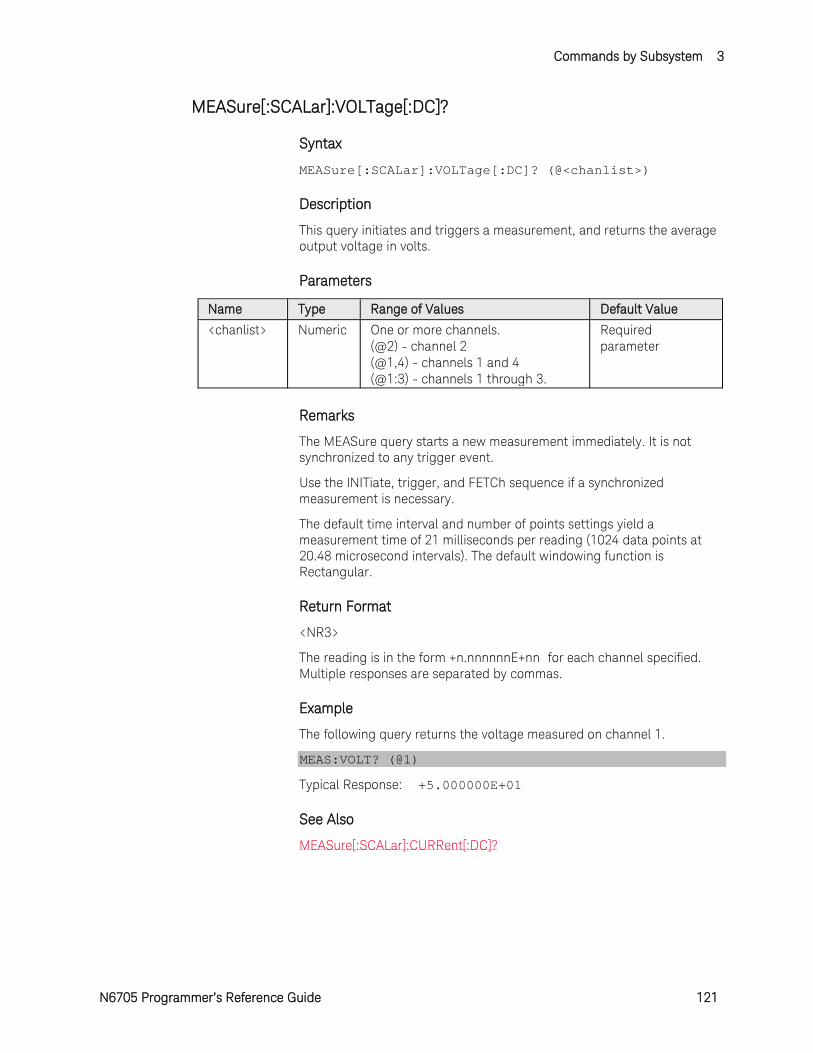
Commands by Subsystem 3
N6705 Programmer’s Reference Guide 121
MEASure[:SCALar]:VOLTage[:DC]?
Syntax
MEASure[:SCALar]:VOLTage[:DC]? (@<chanlist>)
Description
This query initiates and triggers a measurement, and returns the average output voltage in volts.
Parameters
Name Type Range of Values Default Value
<chanlist> Numeric One or more channels. (@2) - channel 2 (@1,4) - channels 1 and 4 (@1:3) - channels 1 through 3.
Required parameter
Remarks
The MEASure query starts a new measurement immediately. It is not synchronized to any trigger event.
Use the INITiate, trigger, and FETCh sequence if a synchronized measurement is necessary.
The default time interval and number of points settings yield a measurement time of 21 milliseconds per reading (1024 data points at 20.48 microsecond intervals). The default windowing function is Rectangular.
Return Format
<NR3>
The reading is in the form +n.nnnnnnE+nn for each channel specified. Multiple responses are separated by commas.
Example
The following query returns the voltage measured on channel 1.
MEAS:VOLT? (@1)
Typical Response: +5.000000E+01
See Also
MEASure[:SCALar]:CURRent[:DC]?
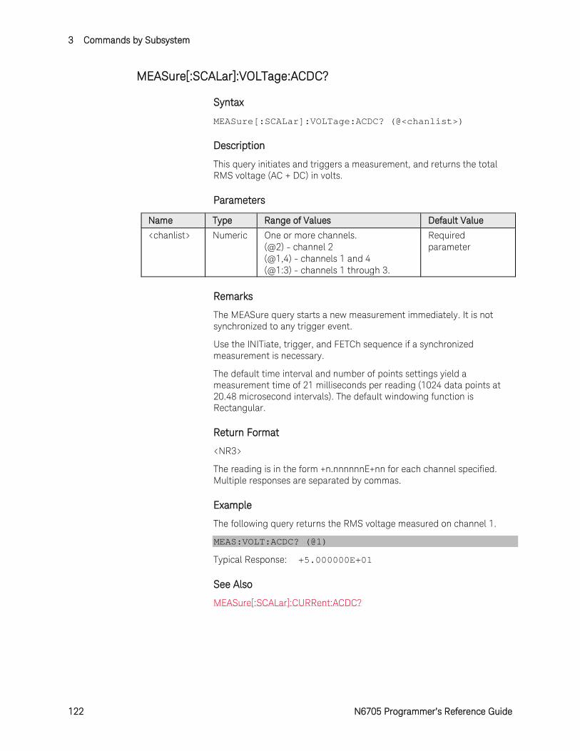
3 Commands by Subsystem
122 N6705 Programmer’s Reference Guide
MEASure[:SCALar]:VOLTage:ACDC?
Syntax
MEASure[:SCALar]:VOLTage:ACDC? (@<chanlist>)
Description
This query initiates and triggers a measurement, and returns the total RMS voltage (AC + DC) in volts.
Parameters
Name Type Range of Values Default Value
<chanlist> Numeric One or more channels. (@2) - channel 2 (@1,4) - channels 1 and 4 (@1:3) - channels 1 through 3.
Required parameter
Remarks
The MEASure query starts a new measurement immediately. It is not synchronized to any trigger event.
Use the INITiate, trigger, and FETCh sequence if a synchronized measurement is necessary.
The default time interval and number of points settings yield a measurement time of 21 milliseconds per reading (1024 data points at 20.48 microsecond intervals). The default windowing function is Rectangular.
Return Format
<NR3>
The reading is in the form +n.nnnnnnE+nn for each channel specified. Multiple responses are separated by commas.
Example
The following query returns the RMS voltage measured on channel 1.
MEAS:VOLT:ACDC? (@1)
Typical Response: +5.000000E+01
See Also
MEASure[:SCALar]:CURRent:ACDC?
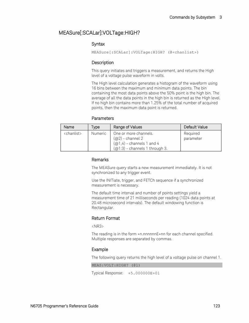
Commands by Subsystem 3
N6705 Programmer’s Reference Guide 123
MEASure[:SCALar]:VOLTage:HIGH?
Syntax
MEASure[:SCALar]:VOLTage:HIGH? (@<chanlist>)
Description
This query initiates and triggers a measurement, and returns the High level of a voltage pulse waveform in volts.
The High level calculation generates a histogram of the waveform using 16 bins between the maximum and minimum data points. The bin containing the most data points above the 50% point is the high bin. The average of all the data points in the high bin is returned as the High level. If no high bin contains more than 1.25% of the total number of acquired points, then the maximum data point is returned.
Parameters
Name Type Range of Values Default Value
<chanlist> Numeric One or more channels. (@2) - channel 2 (@1,4) - channels 1 and 4 (@1:3) - channels 1 through 3.
Required parameter
Remarks
The MEASure query starts a new measurement immediately. It is not synchronized to any trigger event.
Use the INITiate, trigger, and FETCh sequence if a synchronized measurement is necessary.
The default time interval and number of points settings yield a measurement time of 21 milliseconds per reading (1024 data points at 20.48 microsecond intervals). The default windowing function is Rectangular.
Return Format
<NR3>
The reading is in the form +n.nnnnnnE+nn for each channel specified. Multiple responses are separated by commas.
Example
The following query returns the high level of a voltage pulse on channel 1.
MEAS:VOLT:HIGH? (@1)
Typical Response: +5.000000E+01
3 Commands by Subsystem
124 N6705 Programmer’s Reference Guide
See Also
MEASure[:SCALar]:CURRent:HIGH?
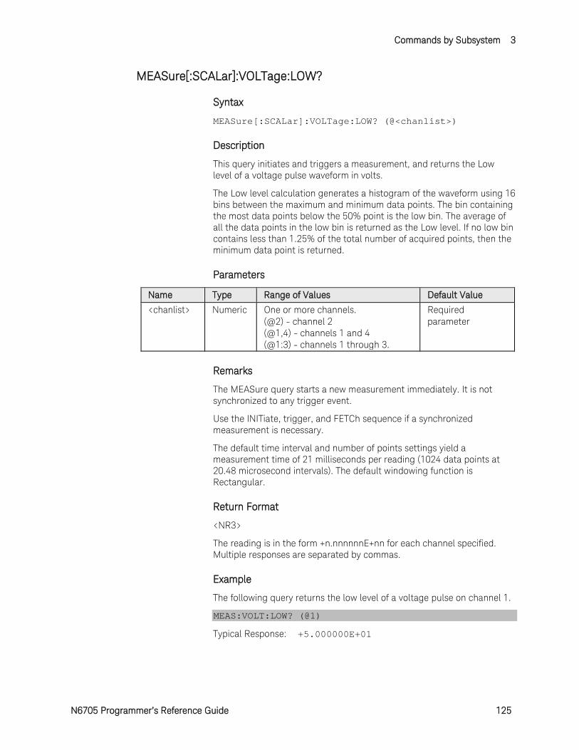
Commands by Subsystem 3
N6705 Programmer’s Reference Guide 125
MEASure[:SCALar]:VOLTage:LOW?
Syntax
MEASure[:SCALar]:VOLTage:LOW? (@<chanlist>)
Description
This query initiates and triggers a measurement, and returns the Low level of a voltage pulse waveform in volts.
The Low level calculation generates a histogram of the waveform using 16 bins between the maximum and minimum data points. The bin containing the most data points below the 50% point is the low bin. The average of all the data points in the low bin is returned as the Low level. If no low bin contains less than 1.25% of the total number of acquired points, then the minimum data point is returned.
Parameters
Name Type Range of Values Default Value
<chanlist> Numeric One or more channels. (@2) - channel 2 (@1,4) - channels 1 and 4 (@1:3) - channels 1 through 3.
Required parameter
Remarks
The MEASure query starts a new measurement immediately. It is not synchronized to any trigger event.
Use the INITiate, trigger, and FETCh sequence if a synchronized measurement is necessary.
The default time interval and number of points settings yield a measurement time of 21 milliseconds per reading (1024 data points at 20.48 microsecond intervals). The default windowing function is Rectangular.
Return Format
<NR3>
The reading is in the form +n.nnnnnnE+nn for each channel specified. Multiple responses are separated by commas.
Example
The following query returns the low level of a voltage pulse on channel 1.
MEAS:VOLT:LOW? (@1)
Typical Response: +5.000000E+01

3 Commands by Subsystem
126 N6705 Programmer’s Reference Guide
See Also
MEASure[:SCALar]:CURRent:LOW?
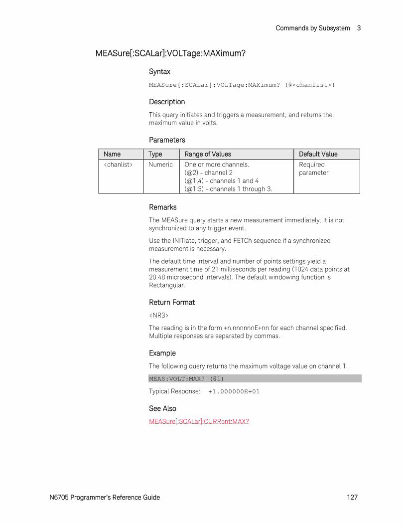
Commands by Subsystem 3
N6705 Programmer’s Reference Guide 127
MEASure[:SCALar]:VOLTage:MAXimum?
Syntax
MEASure[:SCALar]:VOLTage:MAXimum? (@<chanlist>)
Description
This query initiates and triggers a measurement, and returns the maximum value in volts.
Parameters
Name Type Range of Values Default Value
<chanlist> Numeric One or more channels. (@2) - channel 2 (@1,4) - channels 1 and 4 (@1:3) - channels 1 through 3.
Required parameter
Remarks
The MEASure query starts a new measurement immediately. It is not synchronized to any trigger event.
Use the INITiate, trigger, and FETCh sequence if a synchronized measurement is necessary.
The default time interval and number of points settings yield a measurement time of 21 milliseconds per reading (1024 data points at 20.48 microsecond intervals). The default windowing function is Rectangular.
Return Format
<NR3>
The reading is in the form +n.nnnnnnE+nn for each channel specified. Multiple responses are separated by commas.
Example
The following query returns the maximum voltage value on channel 1.
MEAS:VOLT:MAX? (@1)
Typical Response: +1.000000E+01
See Also
MEASure[:SCALar]:CURRent:MAX?
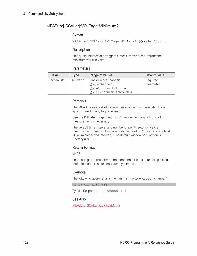
3 Commands by Subsystem
128 N6705 Programmer’s Reference Guide
MEASure[:SCALar]:VOLTage:MINimum?
Syntax
MEASure[:SCALar]:VOLTage:MINimum? (@<<chanlist>>)
Description
This query initiates and triggers a measurement, and returns the minimum value in volts.
Parameters
Name Type Range of Values Default Value
<chanlist> Numeric One or more channels. (@2) - channel 2 (@1,4) - channels 1 and 4 (@1:3) - channels 1 through 3.
Required parameter
Remarks
The MEASure query starts a new measurement immediately. It is not synchronized to any trigger event.
Use the INITiate, trigger, and FETCh sequence if a synchronized measurement is necessary.
The default time interval and number of points settings yield a measurement time of 21 milliseconds per reading (1024 data points at 20.48 microsecond intervals). The default windowing function is Rectangular.
Return Format
<NR3>
The reading is in the form +n.nnnnnnE+nn for each channel specified. Multiple responses are separated by commas.
Example
The following query returns the minimum voltage value on channel 1.
MEAS:VOLT:MIN? (@1)
Typical Response: +1.000000E+01
See Also
MEASure[:SCALar]:CURRent:MIN?

Commands by Subsystem 3
N6705 Programmer’s Reference Guide 129
MEASure:ARRay:CURRent[:DC]?
Syntax
MEASure:ARRay:CURRent[:DC]? (@<<chanlist>>)
Description
This query initiates and triggers a measurement and returns an array containing the digitized output current in amperes.
The sampling rate is set by SENSe:SWEep:TINTerval. The position of the trigger relative to the beginning of the data buffer is determined by SENSe:SWEep:OFFSet:POINTs. The number of points returned is set by SENSe:SWEep:POINts.
Parameters
Name Type Range of Values Default Value
<chanlist> Numeric One or more channels. (@2) - channel 2 (@1,4) - channels 1 and 4 (@1:3) - channels 1 through 3.
Required parameter
Remarks
The MEASure query starts a new measurement immediately. It is not synchronized to any trigger event.
Use the INITiate, trigger, and FETCh sequence if a synchronized measurement is necessary.
The default time interval and number of points settings yield a measurement time of 21 milliseconds per reading (1024 data points at 20.48 microsecond intervals). The default windowing function is Rectangular.
Return Format
The return format depends on the settings of the FORMat:BORDer and FORMat[:DATA] commands. When the data format is set to ASCII, returned values are comma separated. Only one channel can be queried when the format is ASCII. When the data format is set to REAL, data is returned as single precision floating point numbers in definite length arbitrary block response format. Each block contains all the records for one of the channels given in the <chanlist> parameter. If multiple channels are given, then each definite length arbitrary block of data is separated by a comma.
<NR3> [,<NR3>] or <block> [,<block>]

3 Commands by Subsystem
130 N6705 Programmer’s Reference Guide
Example
The following query returns the current measured on channel 1.
MEAS:ARR:CURR? (@1)
See Also
MEASure:ARRay:VOLTage[:DC]?
SENSe:SWEep:TINTerval
SENSe:SWEep:OFFset:POINts
SENSe:SWEep:POINts
FORMat:BORDer
FORMat[:DATA]
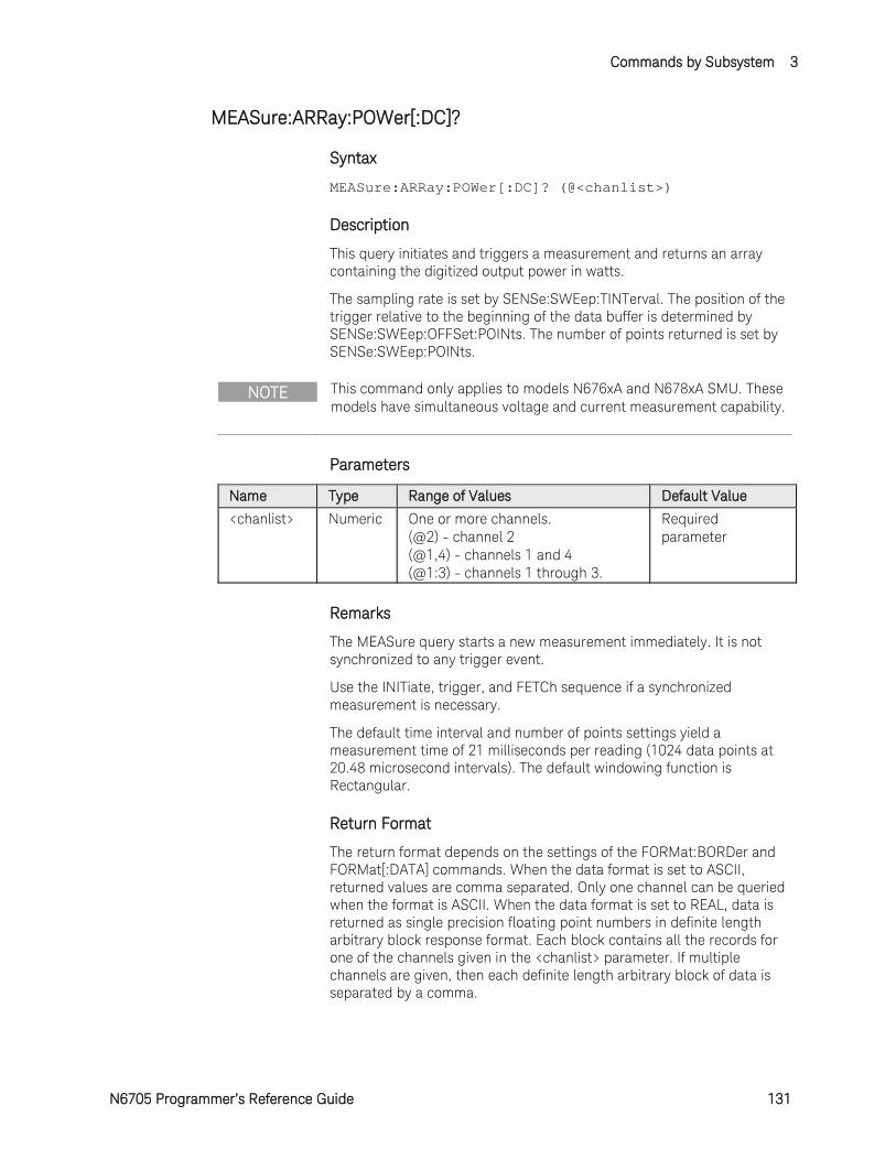
Commands by Subsystem 3
N6705 Programmer’s Reference Guide 131
MEASure:ARRay:POWer[:DC]?
Syntax
MEASure:ARRay:POWer[:DC]? (@<chanlist>)
Description
This query initiates and triggers a measurement and returns an array containing the digitized output power in watts.
The sampling rate is set by SENSe:SWEep:TINTerval. The position of the trigger relative to the beginning of the data buffer is determined by SENSe:SWEep:OFFSet:POINts. The number of points returned is set by SENSe:SWEep:POINts.
NOTE This command only applies to models N676xA and N678xA SMU. These models have simultaneous voltage and current measurement capability.
Parameters
Name Type Range of Values Default Value
<chanlist> Numeric One or more channels. (@2) - channel 2 (@1,4) - channels 1 and 4 (@1:3) - channels 1 through 3.
Required parameter
Remarks
The MEASure query starts a new measurement immediately. It is not synchronized to any trigger event.
Use the INITiate, trigger, and FETCh sequence if a synchronized measurement is necessary.
The default time interval and number of points settings yield a measurement time of 21 milliseconds per reading (1024 data points at 20.48 microsecond intervals). The default windowing function is Rectangular.
Return Format
The return format depends on the settings of the FORMat:BORDer and FORMat[:DATA] commands. When the data format is set to ASCII, returned values are comma separated. Only one channel can be queried when the format is ASCII. When the data format is set to REAL, data is returned as single precision floating point numbers in definite length arbitrary block response format. Each block contains all the records for one of the channels given in the <chanlist> parameter. If multiple channels are given, then each definite length arbitrary block of data is separated by a comma.
3 Commands by Subsystem
132 N6705 Programmer’s Reference Guide
<NR3> [,<NR3>] or <block> [,<block>]
Example
The following query returns the power measured on channel 1.
MEAS:ARR:POW? (@1)
See Also
SENSe:SWEep:TINTerval
SENSe:SWEep:OFFset:POINts
SENSe:SWEep:POINts
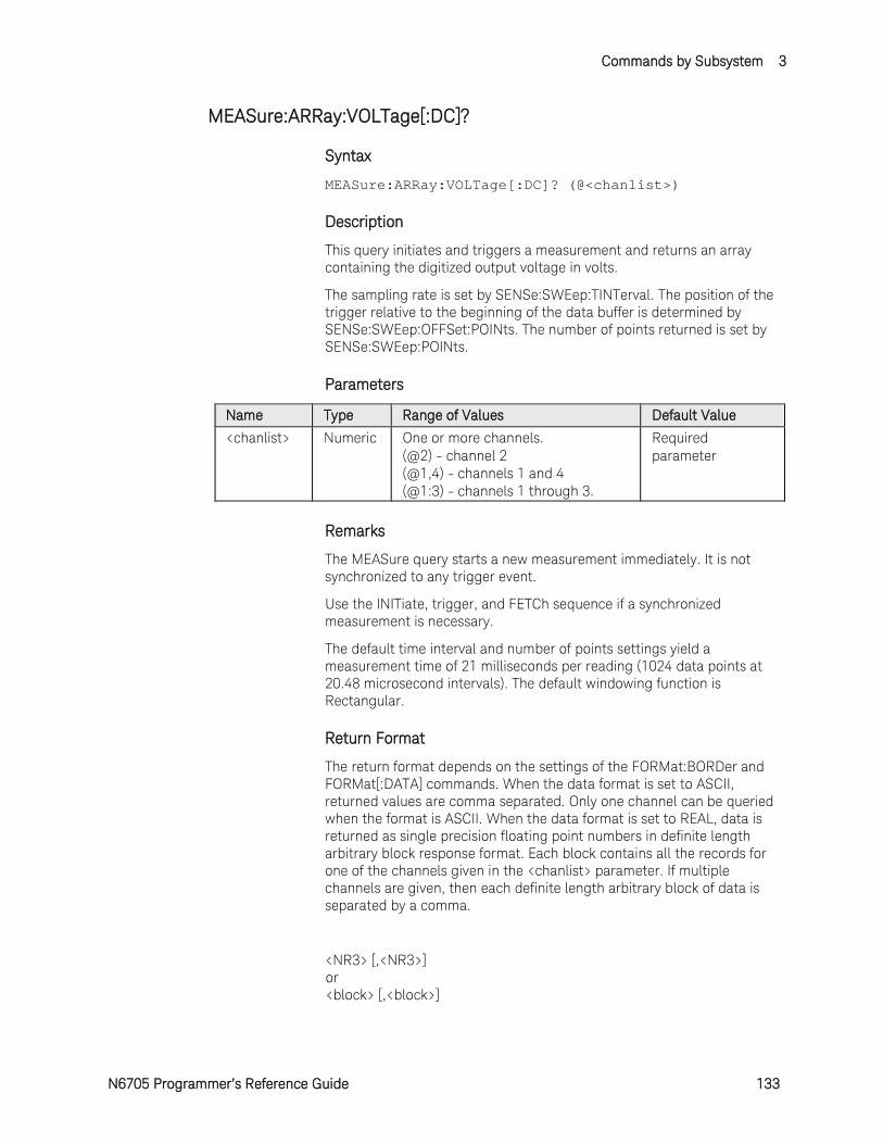
Commands by Subsystem 3
N6705 Programmer’s Reference Guide 133
MEASure:ARRay:VOLTage[:DC]?
Syntax
MEASure:ARRay:VOLTage[:DC]? (@<chanlist>)
Description
This query initiates and triggers a measurement and returns an array containing the digitized output voltage in volts.
The sampling rate is set by SENSe:SWEep:TINTerval. The position of the trigger relative to the beginning of the data buffer is determined by SENSe:SWEep:OFFSet:POINts. The number of points returned is set by SENSe:SWEep:POINts.
Parameters
Name Type Range of Values Default Value
<chanlist> Numeric One or more channels. (@2) - channel 2 (@1,4) - channels 1 and 4 (@1:3) - channels 1 through 3.
Required parameter
Remarks
The MEASure query starts a new measurement immediately. It is not synchronized to any trigger event.
Use the INITiate, trigger, and FETCh sequence if a synchronized measurement is necessary.
The default time interval and number of points settings yield a measurement time of 21 milliseconds per reading (1024 data points at 20.48 microsecond intervals). The default windowing function is Rectangular.
Return Format
The return format depends on the settings of the FORMat:BORDer and FORMat[:DATA] commands. When the data format is set to ASCII, returned values are comma separated. Only one channel can be queried when the format is ASCII. When the data format is set to REAL, data is returned as single precision floating point numbers in definite length arbitrary block response format. Each block contains all the records for one of the channels given in the <chanlist> parameter. If multiple channels are given, then each definite length arbitrary block of data is separated by a comma.
<NR3> [,<NR3>] or <block> [,<block>]
3 Commands by Subsystem
134 N6705 Programmer’s Reference Guide
Example
The following query returns the voltage measured on channel 1.
MEAS:ARR:VOLT? (@1)
See Also
MEASure:ARRay:CURRent[:DC]?
SENSe:SWEep:TINTerval
SENSe:SWEep:OFFset:POINts
SENSe:SWEep:POINts
FORMat:BORDer
FORMat[:DATA]
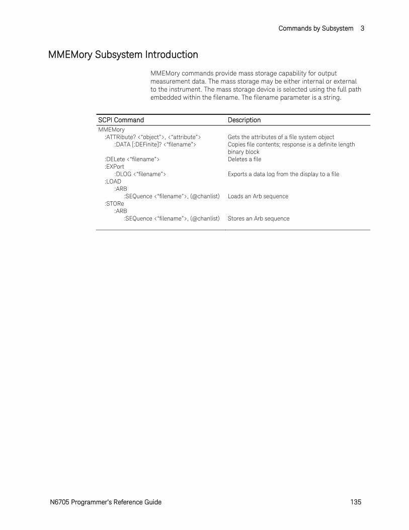
Commands by Subsystem 3
N6705 Programmer’s Reference Guide 135
MMEMory Subsystem Introduction
MMEMory commands provide mass storage capability for output measurement data. The mass storage may be either internal or external to the instrument. The mass storage device is selected using the full path embedded within the filename. The filename parameter is a string.
SCPI Command Description MMEMory :ATTRibute? <“object”>, <“attribute”> Gets the attributes of a file system object :DATA [:DEFinite]? <“filename”> Copies file contents; response is a definite length
binary block :DELete <“filename”> Deletes a file :EXPort :DLOG <“filename”> Exports a data log from the display to a file :LOAD :ARB :SEQuence <“filename”>, (@chanlist) Loads an Arb sequence :STORe :ARB :SEQuence <“filename”>, (@chanlist) Stores an Arb sequence
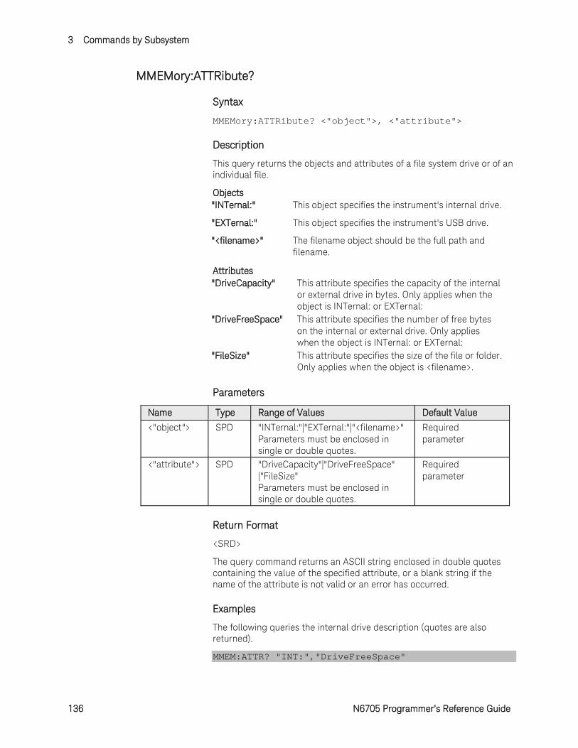
3 Commands by Subsystem
136 N6705 Programmer’s Reference Guide
MMEMory:ATTRibute?
Syntax
MMEMory:ATTRibute? <"object">, <"attribute">
Description
This query returns the objects and attributes of a file system drive or of an individual file.
Objects "INTernal:" This object specifies the instrument's internal drive.
"EXTernal:" This object specifies the instrument's USB drive.
"<filename>" The filename object should be the full path and filename.
Attributes "DriveCapacity" This attribute specifies the capacity of the internal
or external drive in bytes. Only applies when the object is INTernal: or EXTernal:
"DriveFreeSpace" This attribute specifies the number of free bytes on the internal or external drive. Only applies when the object is INTernal: or EXTernal:
"FileSize" This attribute specifies the size of the file or folder. Only applies when the object is <filename>.
Parameters
Name Type Range of Values Default Value <"object"> SPD "INTernal:"|"EXTernal:"|"<filename>"
Parameters must be enclosed in single or double quotes.
Required parameter
<"attribute"> SPD "DriveCapacity"|"DriveFreeSpace" |"FileSize" Parameters must be enclosed in single or double quotes.
Required parameter
Return Format
<SRD>
The query command returns an ASCII string enclosed in double quotes containing the value of the specified attribute, or a blank string if the name of the attribute is not valid or an error has occurred.
Examples
The following queries the internal drive description (quotes are also returned).
MMEM:ATTR? "INT:","DriveFreeSpace"
Commands by Subsystem 3
N6705 Programmer’s Reference Guide 137
Typical Response: "63422464"
The following queries the attributes of a data log file (quotes are also returned).
MMEM:ATTR? "INT:\datalog\data1.dlog","FileSize"
Typical Response: "112770"
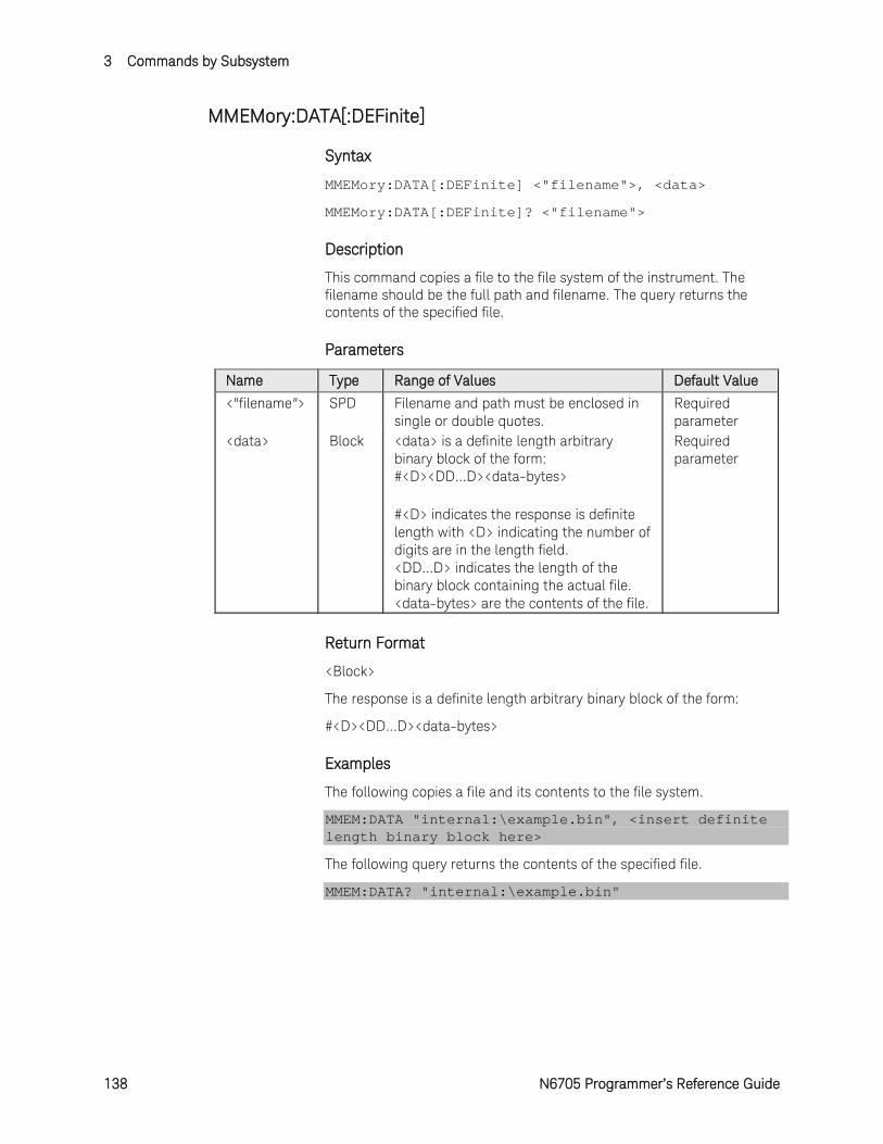
3 Commands by Subsystem
138 N6705 Programmer’s Reference Guide
MMEMory:DATA[:DEFinite]
Syntax
MMEMory:DATA[:DEFinite] <"filename">, <data>
MMEMory:DATA[:DEFinite]? <"filename">
Description
This command copies a file to the file system of the instrument. The filename should be the full path and filename. The query returns the contents of the specified file.
Parameters
Name Type Range of Values Default Value <"filename"> SPD Filename and path must be enclosed in
single or double quotes. Required parameter
<data> Block <data> is a definite length arbitrary binary block of the form: #<D><DD...D><data-bytes>
#<D> indicates the response is definite length with <D> indicating the number of digits are in the length field. <DD...D> indicates the length of the binary block containing the actual file. <data-bytes> are the contents of the file.
Required parameter
Return Format
<Block>
The response is a definite length arbitrary binary block of the form:
#<D><DD...D><data-bytes>
Examples
The following copies a file and its contents to the file system.
MMEM:DATA "internal:\example.bin", <insert definite length binary block here>
The following query returns the contents of the specified file.
MMEM:DATA? "internal:\example.bin"
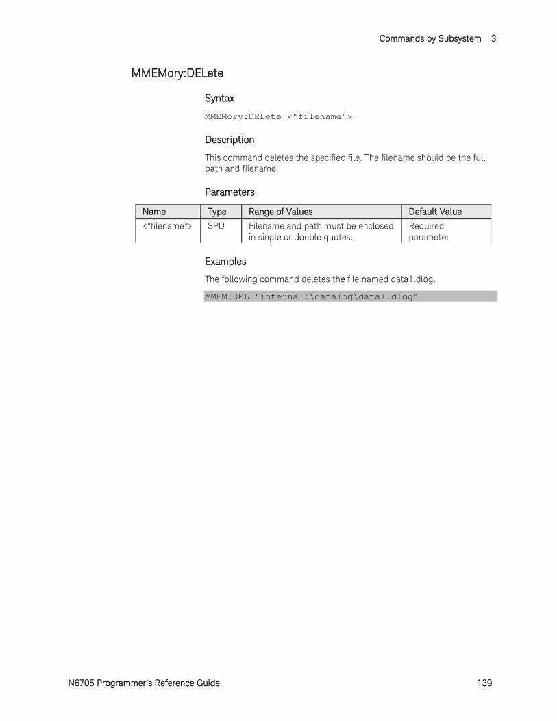
Commands by Subsystem 3
N6705 Programmer’s Reference Guide 139
MMEMory:DELete
Syntax
MMEMory:DELete <"filename">
Description
This command deletes the specified file. The filename should be the full path and filename.
Parameters
Name Type Range of Values Default Value <"filename"> SPD Filename and path must be enclosed
in single or double quotes. Required parameter
Examples
The following command deletes the file named data1.dlog.
MMEM:DEL "internal:\datalog\data1.dlog"
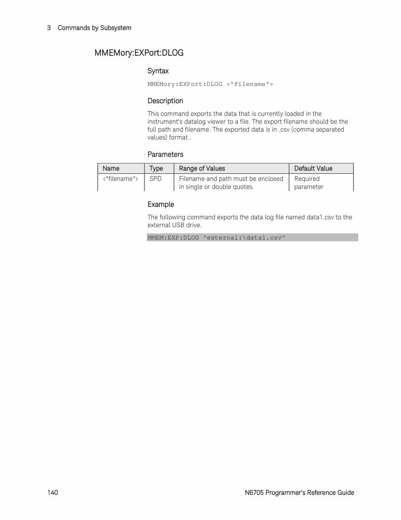
3 Commands by Subsystem
140 N6705 Programmer’s Reference Guide
MMEMory:EXPort:DLOG
Syntax
MMEMory:EXPort:DLOG <"filename">
Description
This command exports the data that is currently loaded in the instrument's datalog viewer to a file. The export filename should be the full path and filename. The exported data is in .csv (comma separated values) format .
Parameters
Name Type Range of Values Default Value <"filename"> SPD Filename and path must be enclosed
in single or double quotes. Required parameter
Example
The following command exports the data log file named data1.csv to the external USB drive.
MMEM:EXP:DLOG "external:\data1.csv"
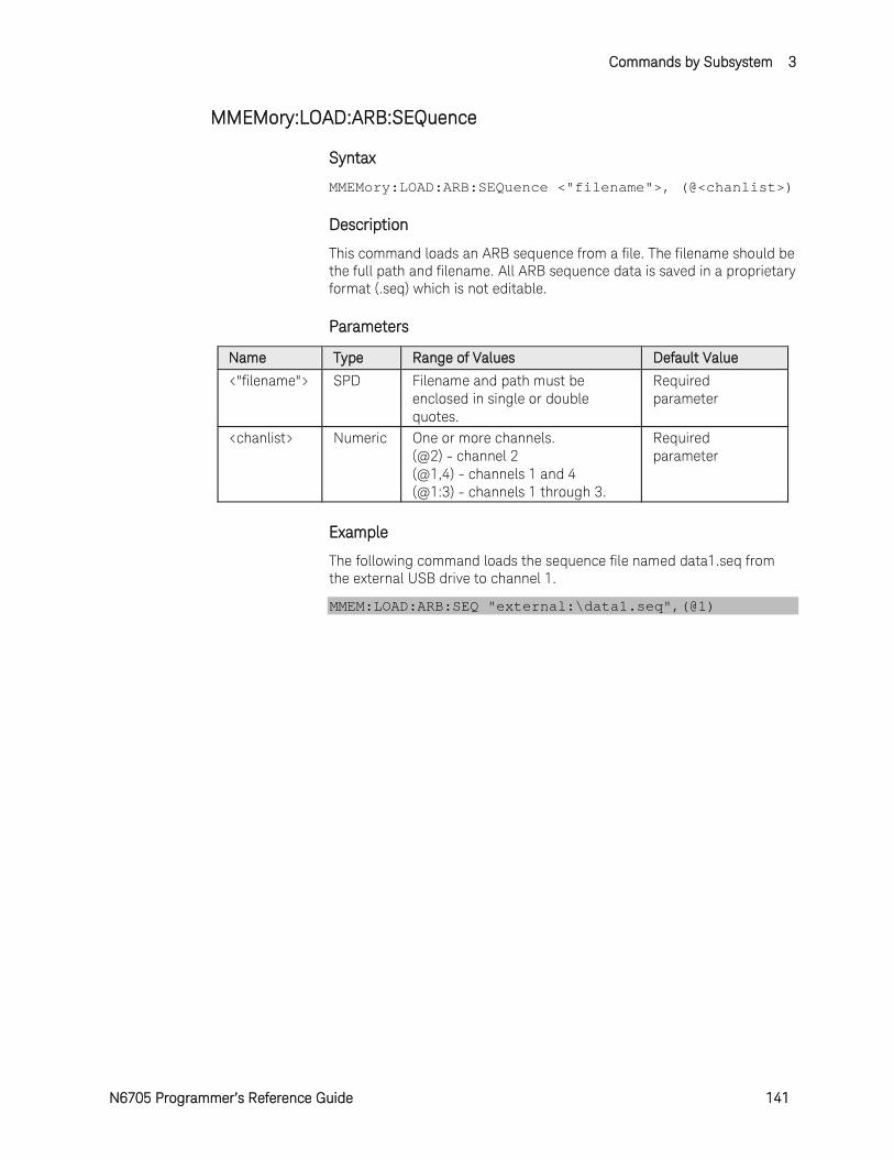
Commands by Subsystem 3
N6705 Programmer’s Reference Guide 141
MMEMory:LOAD:ARB:SEQuence
Syntax
MMEMory:LOAD:ARB:SEQuence <"filename">, (@<chanlist>)
Description
This command loads an ARB sequence from a file. The filename should be the full path and filename. All ARB sequence data is saved in a proprietary format (.seq) which is not editable.
Parameters
Name Type Range of Values Default Value <"filename"> SPD Filename and path must be
enclosed in single or double quotes.
Required parameter
<chanlist> Numeric One or more channels. (@2) - channel 2 (@1,4) - channels 1 and 4 (@1:3) - channels 1 through 3.
Required parameter
Example
The following command loads the sequence file named data1.seq from the external USB drive to channel 1.
MMEM:LOAD:ARB:SEQ "external:\data1.seq",(@1)
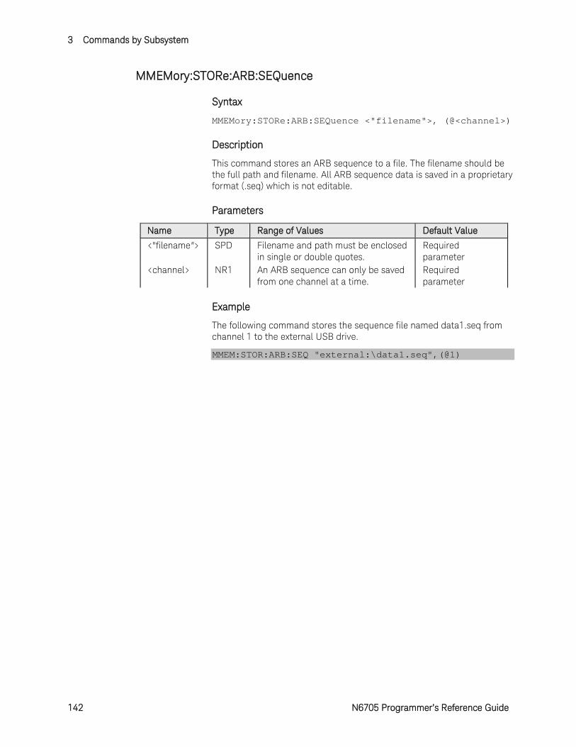
3 Commands by Subsystem
142 N6705 Programmer’s Reference Guide
MMEMory:STORe:ARB:SEQuence
Syntax
MMEMory:STORe:ARB:SEQuence <"filename">, (@<channel>)
Description
This command stores an ARB sequence to a file. The filename should be the full path and filename. All ARB sequence data is saved in a proprietary format (.seq) which is not editable.
Parameters
Name Type Range of Values Default Value <"filename"> SPD Filename and path must be enclosed
in single or double quotes. Required parameter
<channel> NR1 An ARB sequence can only be saved from one channel at a time.
Required parameter
Example
The following command stores the sequence file named data1.seq from channel 1 to the external USB drive.
MMEM:STOR:ARB:SEQ "external:\data1.seq",(@1)
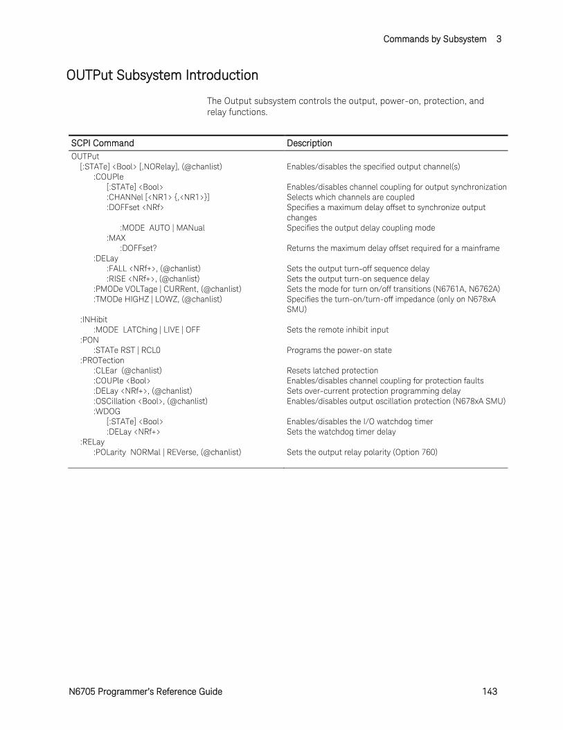
Commands by Subsystem 3
N6705 Programmer’s Reference Guide 143
OUTPut Subsystem Introduction
The Output subsystem controls the output, power-on, protection, and relay functions.
SCPI Command Description OUTPut [:STATe] <Bool> [,NORelay], (@chanlist) Enables/disables the specified output channel(s) :COUPle [:STATe] <Bool> Enables/disables channel coupling for output synchronization :CHANNel [<NR1> ,<NR1>] Selects which channels are coupled :DOFFset <NRf> Specifies a maximum delay offset to synchronize output
changes :MODE AUTO | MANual Specifies the output delay coupling mode :MAX :DOFFset? Returns the maximum delay offset required for a mainframe :DELay :FALL <NRf+>, (@chanlist) Sets the output turn-off sequence delay :RISE <NRf+>, (@chanlist) Sets the output turn-on sequence delay :PMODe VOLTage | CURRent, (@chanlist) Sets the mode for turn on/off transitions (N6761A, N6762A) :TMODe HIGHZ | LOWZ, (@chanlist) Specifies the turn-on/turn-off impedance (only on N678xA
SMU) :INHibit :MODE LATChing | LIVE | OFF Sets the remote inhibit input :PON :STATe RST | RCL0 Programs the power-on state :PROTection :CLEar (@chanlist) Resets latched protection :COUPle <Bool> Enables/disables channel coupling for protection faults :DELay <NRf+>, (@chanlist) Sets over-current protection programming delay :OSCillation <Bool>, (@chanlist) Enables/disables output oscillation protection (N678xA SMU) :WDOG [:STATe] <Bool> Enables/disables the I/O watchdog timer :DELay <NRf+> Sets the watchdog timer delay :RELay :POLarity NORMal | REVerse, (@chanlist) Sets the output relay polarity (Option 760)
3 Commands by Subsystem
144 N6705 Programmer’s Reference Guide
OUTPut[:STATe]
Syntax
OUTPut[:STATe] <Bool> [,NORelay], (@<chanlist>)
OUTPut[:STATe]? (@<chanlist>)
Description
This command enables or disables the specified output channel(s). The enabled state is ON (1); the disabled state is OFF (0). The state of a disabled output is a condition of zero output voltage and zero source current. If output and sense relays are installed (Option 761), the relays will open when the output is disabled and close when the output is enabled.
The optional NORelay parameter lets you turn the output state on or off and leave the state of the relays unchanged. When not specified, the relays open and close as the output is turned off and on. Relays only open and close when the output is at zero voltage; zero current.
Parameters
Name Type Range of Values Default Value
<Bool> Boolean OFF | 0 | ON | 1 OFF
<chanlist> Numeric One or more channels. (@2) - channel 2 (@1,4) - channels 1 and 4 (@1:3) - channels 1 through 3.
Required parameter
Remarks
Separate delays can be programmed for the off-to-on and the on-to-off transition using OUTPut:DELay:RISE and OUTput:DELay:FALL.
Because of internal circuit start-up procedures and any installed relay options, the OUTPut ON command may take between 35 and 50 milliseconds to complete its function. The OUTPut OFF command may take between 20 and 25 milliseconds to complete its function. To mitigate this built-in delay, you can program the output to zero volts rather than using the output on/off command.
Return Format
<NR1>
The query command returns 0 if the output is OFF, and 1 if the output is ON.
Example
The following command turns the output of channel 2 on.
OUTP ON,(@2)
Commands by Subsystem 3
N6705 Programmer’s Reference Guide 145
The following query returns the output state of channel 4.
OUTP? (@4)
Typical Response: 0
See Also
OUTPut:PON:STATe
OUTPut[:STATe]:DELay:FALL
OUTPut[:STATe]:DELay:RISE
3 Commands by Subsystem
146 N6705 Programmer’s Reference Guide
OUTPut[:STATe]:COUPle:CHANnel
Syntax
OUTPut[:STATe]:COUPle:CHANnel [<channel> ,<channel>]
OUTPut[:STATe]:COUPle:CHANnel?
Description
This command specifies which output channels in the mainframe are controlled by the output synchronization function. The output channels that have been synchronized or coupled will turn on and off together when any one of them is turned on or off, or when a signal is received from a digital connector pin that has been configured as an On couple or an Off couple pin. Refer to Appendix C in the User's Guide for detailed information.
There can be only one set of coupled channels in a mainframe. If another coupled set is programmed, the existing set is deleted and the new set applies. If you do not specify an output channel, this command will uncouple all output channels on the mainframe.
Parameters
Name Type Range of Values Default Value
<channel> NR1 1 | 2 | 3 | 4 Required parameter
Remarks
When this command is sent, all output channels in the mainframe will go to the output Off state.
This setting is non-volatile and not affected by *RST.
Return Format
<NR1>
The query command returns the channels that are coupled. Multiple responses are separated by commas.
Example
The following command couples channels 1, 2, and 4.
OUTP:COUP:CHAN 1,2,4
The following query returns the output coupling state.
OUTP:COUP:CHAN?
Typical Response: 1,2,4
Commands by Subsystem 3
N6705 Programmer’s Reference Guide 147
See Also
OUTPut[:STATe]:COUPle:DOFFset
[SOURce:]DIGital:PIN<1-7>:FUNCtion
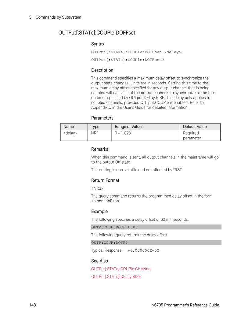
3 Commands by Subsystem
148 N6705 Programmer’s Reference Guide
OUTPut[:STATe]:COUPle:DOFFset
Syntax
OUTPut[:STATe]:COUPle:DOFFset <delay>
OUTPut[:STATe]:COUPle:DOFFset?
Description
This command specifies a maximum delay offset to synchronize the output state changes. Units are in seconds. Setting this time to the maximum delay offset specified for any output channel that is being coupled will cause all of the output channels to synchronize to the turn-on times specified by OUTput:DELay:RISE. This delay only applies to coupled channels, provided OUTput:COUPle is enabled. Refer to Appendix C in the User's Guide for detailed information.
Parameters
Name Type Range of Values Default Value
<delay> NRf 0 - 1.023 Required parameter
Remarks
When this command is sent, all output channels in the mainframe will go to the output Off state.
This setting is non-volatile and not affected by *RST.
Return Format
<NR3>
The query command returns the programmed delay offset in the form +n.nnnnnnE+nn.
Example
The following specifies a delay offset of 60 milliseconds.
OUTP:COUP:DOFF 0.06
The following query returns the delay offset.
OUTP:COUP:DOFF?
Typical Response: +6.000000E-02
See Also
OUTPut[:STATe]:COUPle:CHANnel
OUTPut[:STATe]:DELay:RISE
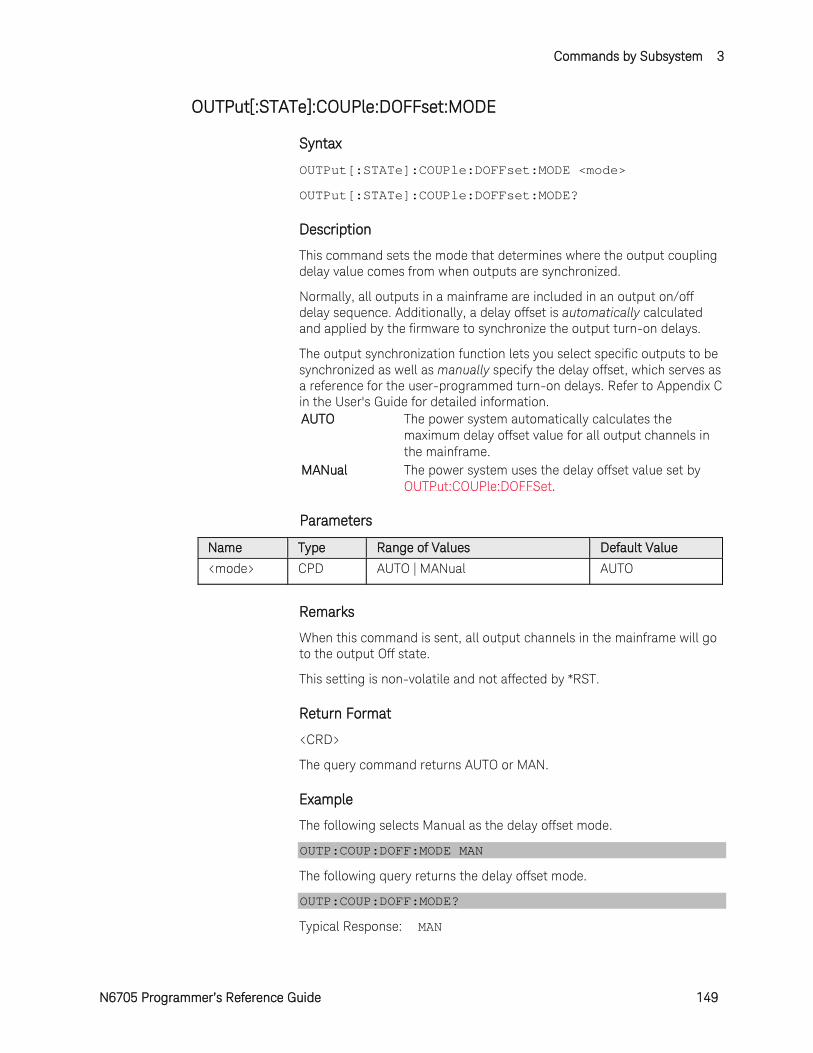
Commands by Subsystem 3
N6705 Programmer’s Reference Guide 149
OUTPut[:STATe]:COUPle:DOFFset:MODE
Syntax
OUTPut[:STATe]:COUPle:DOFFset:MODE <mode>
OUTPut[:STATe]:COUPle:DOFFset:MODE?
Description
This command sets the mode that determines where the output coupling delay value comes from when outputs are synchronized.
Normally, all outputs in a mainframe are included in an output on/off delay sequence. Additionally, a delay offset is automatically calculated and applied by the firmware to synchronize the output turn-on delays.
The output synchronization function lets you select specific outputs to be synchronized as well as manually specify the delay offset, which serves as a reference for the user-programmed turn-on delays. Refer to Appendix C in the User's Guide for detailed information. AUTO The power system automatically calculates the
maximum delay offset value for all output channels in the mainframe.
MANual The power system uses the delay offset value set by OUTPut:COUPle:DOFFSet.
Parameters
Name Type Range of Values Default Value
<mode> CPD AUTO | MANual AUTO
Remarks
When this command is sent, all output channels in the mainframe will go to the output Off state.
This setting is non-volatile and not affected by *RST.
Return Format
<CRD>
The query command returns AUTO or MAN.
Example
The following selects Manual as the delay offset mode.
OUTP:COUP:DOFF:MODE MAN
The following query returns the delay offset mode.
OUTP:COUP:DOFF:MODE?
Typical Response: MAN

3 Commands by Subsystem
150 N6705 Programmer’s Reference Guide
See Also
OUTPut[:STATe]:COUPle:DOFFset
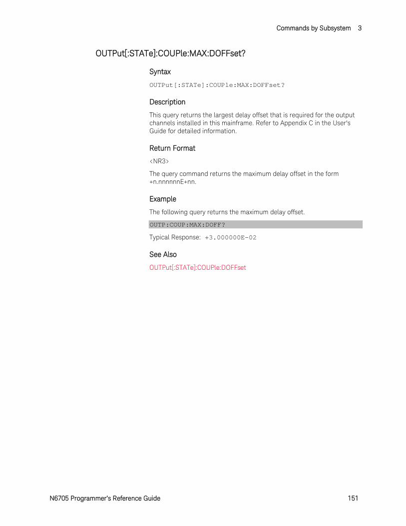
Commands by Subsystem 3
N6705 Programmer’s Reference Guide 151
OUTPut[:STATe]:COUPle:MAX:DOFFset?
Syntax
OUTPut[:STATe]:COUPle:MAX:DOFFset?
Description
This query returns the largest delay offset that is required for the output channels installed in this mainframe. Refer to Appendix C in the User's Guide for detailed information.
Return Format
<NR3>
The query command returns the maximum delay offset in the form +n.nnnnnnE+nn.
Example
The following query returns the maximum delay offset.
OUTP:COUP:MAX:DOFF?
Typical Response: +3.000000E-02
See Also
OUTPut[:STATe]:COUPle:DOFFset
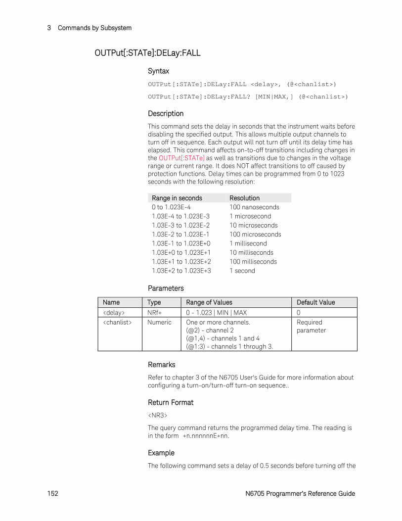
3 Commands by Subsystem
152 N6705 Programmer’s Reference Guide
OUTPut[:STATe]:DELay:FALL
Syntax
OUTPut[:STATe]:DELay:FALL <delay>, (@<chanlist>)
OUTPut[:STATe]:DELay:FALL? [MIN|MAX,] (@<chanlist>)
Description
This command sets the delay in seconds that the instrument waits before disabling the specified output. This allows multiple output channels to turn off in sequence. Each output will not turn off until its delay time has elapsed. This command affects on-to-off transitions including changes in the OUTPut[:STATe] as well as transitions due to changes in the voltage range or current range. It does NOT affect transitions to off caused by protection functions. Delay times can be programmed from 0 to 1023 seconds with the following resolution:
Range in seconds Resolution 0 to 1.023E-4 100 nanoseconds 1.03E-4 to 1.023E-3 1 microsecond 1.03E-3 to 1.023E-2 10 microseconds 1.03E-2 to 1.023E-1 100 microseconds 1.03E-1 to 1.023E+0 1 millisecond 1.03E+0 to 1.023E+1 10 milliseconds 1.03E+1 to 1.023E+2 100 milliseconds 1.03E+2 to 1.023E+3 1 second
Parameters
Name Type Range of Values Default Value
<delay> NRf+ 0 - 1.023 | MIN | MAX 0 <chanlist> Numeric One or more channels.
(@2) - channel 2 (@1,4) - channels 1 and 4 (@1:3) - channels 1 through 3.
Required parameter
Remarks
Refer to chapter 3 of the N6705 User's Guide for more information about configuring a turn-on/turn-off turn-on sequence..
Return Format
<NR3>
The query command returns the programmed delay time. The reading is in the form +n.nnnnnnE+nn.
Example
The following command sets a delay of 0.5 seconds before turning off the
Commands by Subsystem 3
N6705 Programmer’s Reference Guide 153
output of channel 2.
OUTP:DEL:FALL 0.5,(@2)
The following query returns the maximum allowable delay time of channel 1.
OUTP:DEL:FALL? MAX,(@1)
Typical Response: +1.023000E+00
See Also
OUTPut[:STATe]
OUTPut[:STATe]:DELay:RISE
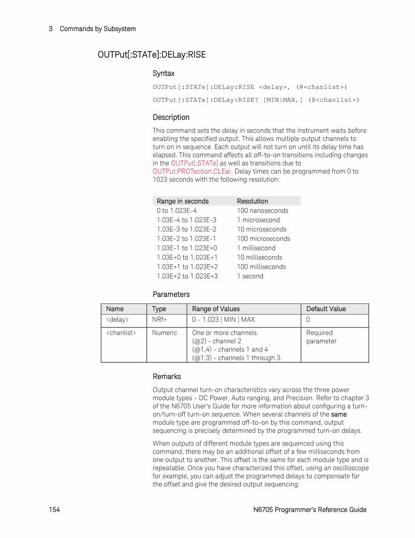
3 Commands by Subsystem
154 N6705 Programmer’s Reference Guide
OUTPut[:STATe]:DELay:RISE
Syntax
OUTPut[:STATe]:DELay:RISE <delay>, (@<chanlist>)
OUTPut[:STATe]:DELay:RISE? [MIN|MAX,] (@<chanlist>)
Description
This command sets the delay in seconds that the instrument waits before enabling the specified output. This allows multiple output channels to turn on in sequence. Each output will not turn on until its delay time has elapsed. This command affects all off-to-on transitions including changes in the OUTPut[:STATe] as well as transitions due to OUTPut:PROTection:CLEar. Delay times can be programmed from 0 to 1023 seconds with the following resolution:
Range in seconds Resolution 0 to 1.023E-4 100 nanoseconds 1.03E-4 to 1.023E-3 1 microsecond 1.03E-3 to 1.023E-2 10 microseconds 1.03E-2 to 1.023E-1 100 microseconds 1.03E-1 to 1.023E+0 1 millisecond 1.03E+0 to 1.023E+1 10 milliseconds 1.03E+1 to 1.023E+2 100 milliseconds 1.03E+2 to 1.023E+3 1 second
Parameters
Name Type Range of Values Default Value
<delay> NRf+ 0 - 1.023 | MIN | MAX 0
<chanlist> Numeric One or more channels. (@2) - channel 2 (@1,4) - channels 1 and 4 (@1:3) - channels 1 through 3.
Required parameter
Remarks
Output channel turn-on characteristics vary across the three power module types - DC Power, Auto ranging, and Precision. Refer to chapter 3 of the N6705 User's Guide for more information about configuring a turn-on/turn-off turn-on sequence. When several channels of the same module type are programmed off-to-on by this command, output sequencing is precisely determined by the programmed turn-on delays.
When outputs of different module types are sequenced using this command, there may be an additional offset of a few milliseconds from one output to another. This offset is the same for each module type and is repeatable. Once you have characterized this offset, using an oscilloscope for example, you can adjust the programmed delays to compensate for the offset and give the desired output sequencing.
Commands by Subsystem 3
N6705 Programmer’s Reference Guide 155
Outputs within the same module type can also have an offset if one model has output relays (Option 761) and another does not. These offsets are also repeatable and can be compensated by adjusting the programmed delay values.
Return Format
<NR3>
The query command returns the programmed delay time. The reading is in the form +n.nnnnnnE+nn.
Example
The following command sets a delay of 0.5 seconds before turning on the output of channel 2.
OUTP:DEL:RISE 0.5,(@2)
The following query returns the maximum allowable delay time of channel 1.
OUTP:DEL:RISE? MAX,(@1)
Typical Response: +1.023000E+00
See Also
OUTPut[:STATe]
OUTPut[:STATe]:DELay:FALL
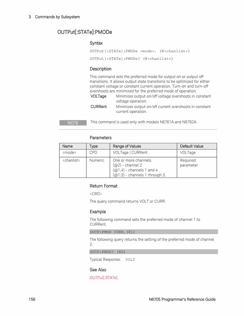
3 Commands by Subsystem
156 N6705 Programmer’s Reference Guide
OUTPut[:STATe]:PMODe
Syntax
OUTPut[:STATe]:PMODe <mode>, (@<chanlist>)
OUTPut[:STATe]:PMODe? (@<chanlist>)
Description
This command sets the preferred mode for output on or output off transitions. It allows output state transitions to be optimized for either constant voltage or constant current operation. Turn-on and turn-off overshoots are minimized for the preferred mode of operation. VOLTage Minimizes output on/off voltage overshoots in constant
voltage operation. CURRent Minimizes output on/off current overshoots in constant
current operation.
NOTE This command is used only with models N6761A and N6762A.
Parameters
Name Type Range of Values Default Value
<mode> CPD VOLTage | CURRent VOLTage
<chanlist> Numeric One or more channels. (@2) - channel 2 (@1,4) - channels 1 and 4 (@1:3) - channels 1 through 3.
Required parameter
Return Format
<CRD>
The query command returns VOLT or CURR.
Example
The following command sets the preferred mode of channel 1 to CURRent.
OUTP:PMOD CURR,(@1)
The following query returns the setting of the preferred mode of channel 2.
OUTP:PMOD? (@2)
Typical Response: VOLT
See Also
OUTPut[:STATe]
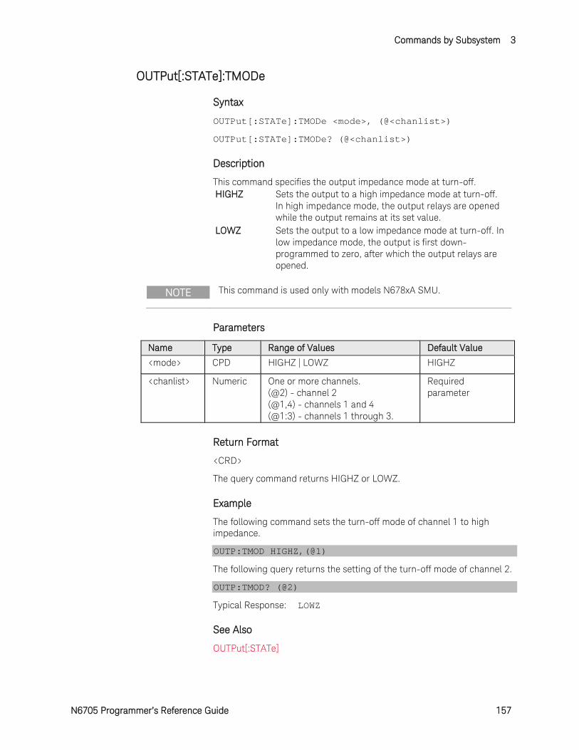
Commands by Subsystem 3
N6705 Programmer’s Reference Guide 157
OUTPut[:STATe]:TMODe
Syntax
OUTPut[:STATe]:TMODe <mode>, (@<chanlist>)
OUTPut[:STATe]:TMODe? (@<chanlist>)
Description
This command specifies the output impedance mode at turn-off. HIGHZ Sets the output to a high impedance mode at turn-off.
In high impedance mode, the output relays are opened while the output remains at its set value.
LOWZ Sets the output to a low impedance mode at turn-off. In low impedance mode, the output is first down-programmed to zero, after which the output relays are opened.
NOTE This command is used only with models N678xA SMU.
Parameters
Name Type Range of Values Default Value
<mode> CPD HIGHZ | LOWZ HIGHZ
<chanlist> Numeric One or more channels. (@2) - channel 2 (@1,4) - channels 1 and 4 (@1:3) - channels 1 through 3.
Required parameter
Return Format
<CRD>
The query command returns HIGHZ or LOWZ.
Example
The following command sets the turn-off mode of channel 1 to high impedance.
OUTP:TMOD HIGHZ,(@1)
The following query returns the setting of the turn-off mode of channel 2.
OUTP:TMOD? (@2)
Typical Response: LOWZ
See Also
OUTPut[:STATe]
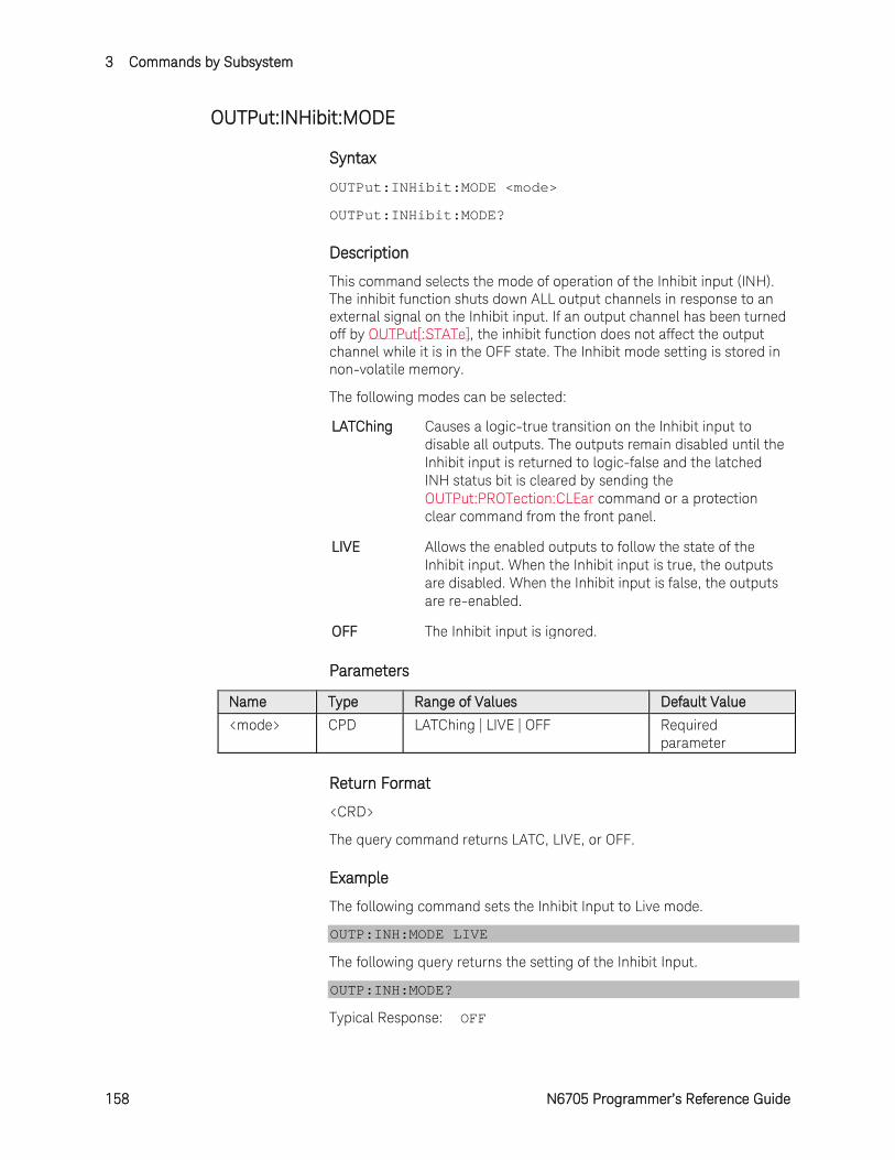
3 Commands by Subsystem
158 N6705 Programmer’s Reference Guide
OUTPut:INHibit:MODE
Syntax
OUTPut:INHibit:MODE <mode>
OUTPut:INHibit:MODE?
Description
This command selects the mode of operation of the Inhibit input (INH). The inhibit function shuts down ALL output channels in response to an external signal on the Inhibit input. If an output channel has been turned off by OUTPut[:STATe], the inhibit function does not affect the output channel while it is in the OFF state. The Inhibit mode setting is stored in non-volatile memory.
The following modes can be selected:
LATChing Causes a logic-true transition on the Inhibit input to disable all outputs. The outputs remain disabled until the Inhibit input is returned to logic-false and the latched INH status bit is cleared by sending the OUTPut:PROTection:CLEar command or a protection clear command from the front panel.
LIVE Allows the enabled outputs to follow the state of the Inhibit input. When the Inhibit input is true, the outputs are disabled. When the Inhibit input is false, the outputs are re-enabled.
OFF The Inhibit input is ignored.
Parameters
Name Type Range of Values Default Value
<mode> CPD LATChing | LIVE | OFF Required parameter
Return Format
<CRD>
The query command returns LATC, LIVE, or OFF.
Example
The following command sets the Inhibit Input to Live mode.
OUTP:INH:MODE LIVE
The following query returns the setting of the Inhibit Input.
OUTP:INH:MODE?
Typical Response: OFF
Commands by Subsystem 3
N6705 Programmer’s Reference Guide 159
See Also
OUTPut[:STATe]
OUTPut:PROTection:CLEar
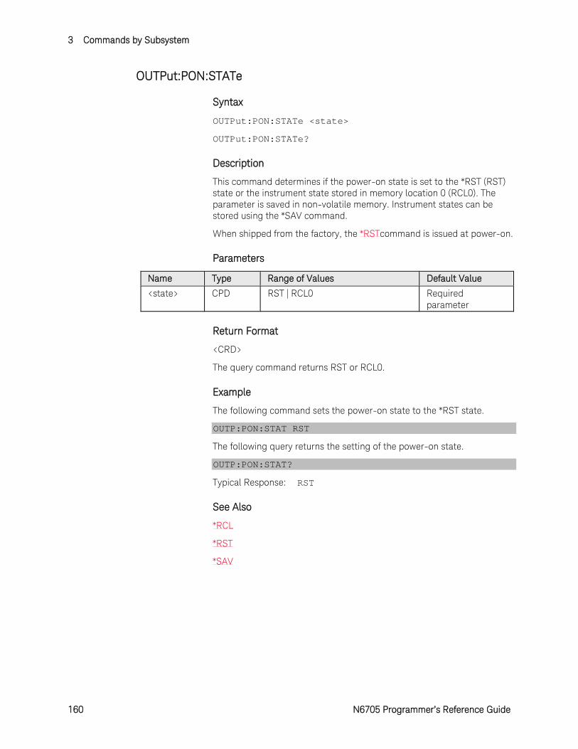
3 Commands by Subsystem
160 N6705 Programmer’s Reference Guide
OUTPut:PON:STATe
Syntax
OUTPut:PON:STATe <state>
OUTPut:PON:STATe?
Description
This command determines if the power-on state is set to the *RST (RST) state or the instrument state stored in memory location 0 (RCL0). The parameter is saved in non-volatile memory. Instrument states can be stored using the *SAV command.
When shipped from the factory, the *RSTcommand is issued at power-on.
Parameters
Name Type Range of Values Default Value
<state> CPD RST | RCL0 Required parameter
Return Format
<CRD>
The query command returns RST or RCL0.
Example
The following command sets the power-on state to the *RST state.
OUTP:PON:STAT RST
The following query returns the setting of the power-on state.
OUTP:PON:STAT?
Typical Response: RST
See Also
*RCL
*RST
*SAV
Commands by Subsystem 3
N6705 Programmer’s Reference Guide 161
OUTPut:PROTection:CLEar
Syntax
OUTPut:PROTection:CLEar (@<chanlist>)
Description
This command clears the latched protection status that disables the output when an over-voltage, over-temperature, over-current, inhibit signal, power-fail condition, or on some models, a power-limit condition is detected.
All conditions that generate the fault must be removed before the latched status can be cleared. The output is restored to the state it was in before the fault condition occurred.
NOTE If a protection shutdown occurs during an output list, the list continues running even though the output is disabled. When the protection status is cleared and the output becomes enabled again, the output will be set to the values of the step that the list is presently at.
Parameters
Name Type Range of Values Default Value
<chanlist> Numeric One or more channels. (@2) - channel 2 (@1,4) - channels 1 and 4 (@1:3) - channels 1 through 3.
Required parameter
Example
The following command clears the latched protection status of channel 1.
OUTP:PROT:CLE (@1)
See Also
OUTPut:PROTection:COUPle
OUTPut:PROTection:DELay
3 Commands by Subsystem
162 N6705 Programmer’s Reference Guide
OUTPut:PROTection:COUPle
Syntax
OUTPut:PROTection:COUPle <Bool>
OUTPut:PROTection:COUPle?
Description
This command enables or disables output coupling for protection faults. When enabled, ALL output channels are disabled when a protection fault occurs on any output channel. The enabled state is On (1); the disabled state is Off (0). When disabled, only the affected output channel is disabled when a protection fault is triggered.
Parameters
Name Type Range of Values Default Value
<Bool> Boolean OFF | 0 | ON | 1 OFF
Return Format
<NR1>
The query command returns 0 if the protection coupling is OFF (disabled), and 1 if the protection coupling is ON (enabled).
Example
The following command enables protection coupling.
OUTP:PROT:COUP ON
The following query returns the protection coupling setting.
OUTP:PROT:COUP?
Typical Response: 0
See Also
OUTPut:PROTection:CLEar
OUTPut:PROTection:DELay
Commands by Subsystem 3
N6705 Programmer’s Reference Guide 163
OUTPut:PROTection:DELay
Syntax
OUTPut:PROTection:DELay <delay>, (@<chanlist>)
OUTPut:PROTection:DELay? [MIN|MAX,] (@<chanlist>)
Description
This command sets the over-current protection delay. The over-current protection function will not be triggered on the specified output channel during the delay time. After the delay time has expired, the over-current protection function will be active. This prevents momentary changes in output status from triggering the over-current protection function. Programmed values can range from 0 to 255 milliseconds in increments of 1 millisecond.
The operation of over-current protection is affected by the setting of the current protection delay start event, which is specified by [SOURce:]CURRent:PROTection:DELay:STARt.
Parameters
Name Type Range of Values Default Value
<delay> NRf+ 0 - 0.255 | MIN | MAX 20 ms
<chanlist> Numeric One or more channels. (@2) - channel 2 (@1,4) - channels 1 and 4 (@1:3) - channels 1 through 3.
Required parameter
Remarks
This command is the same as [SOURce:]CURRent:PROTection:DELay.
Return Format
<NR3>
The query command returns the programmed delay time. The reading is in the form +n.nnnnnnE+nn.
Example
The following command sets a current protection delay of 0.2 seconds for channel 2.
OUTP:PROT:DEL 0.2,(@2)
The following query returns the maximum allowable current protection delay of channel 1.
OUTP:PROT:DEL? MAX,(@1)
Typical Response: +2.550000E-01
3 Commands by Subsystem
164 N6705 Programmer’s Reference Guide
See Also
[SOURce:]CURRent:PROTection:DELay
[SOURce:]CURRent:PROTection:DELay:STARt
[SOURce:]CURRent:PROTection:STATe
OUTPut:PROTection:CLEar
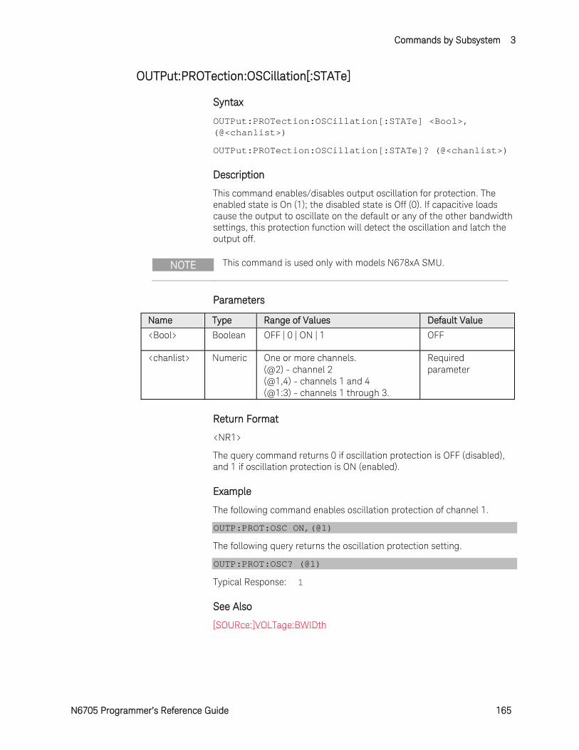
Commands by Subsystem 3
N6705 Programmer’s Reference Guide 165
OUTPut:PROTection:OSCillation[:STATe]
Syntax
OUTPut:PROTection:OSCillation[:STATe] <Bool>, (@<chanlist>)
OUTPut:PROTection:OSCillation[:STATe]? (@<chanlist>)
Description
This command enables/disables output oscillation for protection. The enabled state is On (1); the disabled state is Off (0). If capacitive loads cause the output to oscillate on the default or any of the other bandwidth settings, this protection function will detect the oscillation and latch the output off.
NOTE This command is used only with models N678xA SMU.
Parameters
Name Type Range of Values Default Value
<Bool> Boolean OFF | 0 | ON | 1 OFF
<chanlist> Numeric One or more channels. (@2) - channel 2 (@1,4) - channels 1 and 4 (@1:3) - channels 1 through 3.
Required parameter
Return Format
<NR1>
The query command returns 0 if oscillation protection is OFF (disabled), and 1 if oscillation protection is ON (enabled).
Example
The following command enables oscillation protection of channel 1.
OUTP:PROT:OSC ON,(@1)
The following query returns the oscillation protection setting.
OUTP:PROT:OSC? (@1)
Typical Response: 1
See Also
[SOURce:]VOLTage:BWIDth
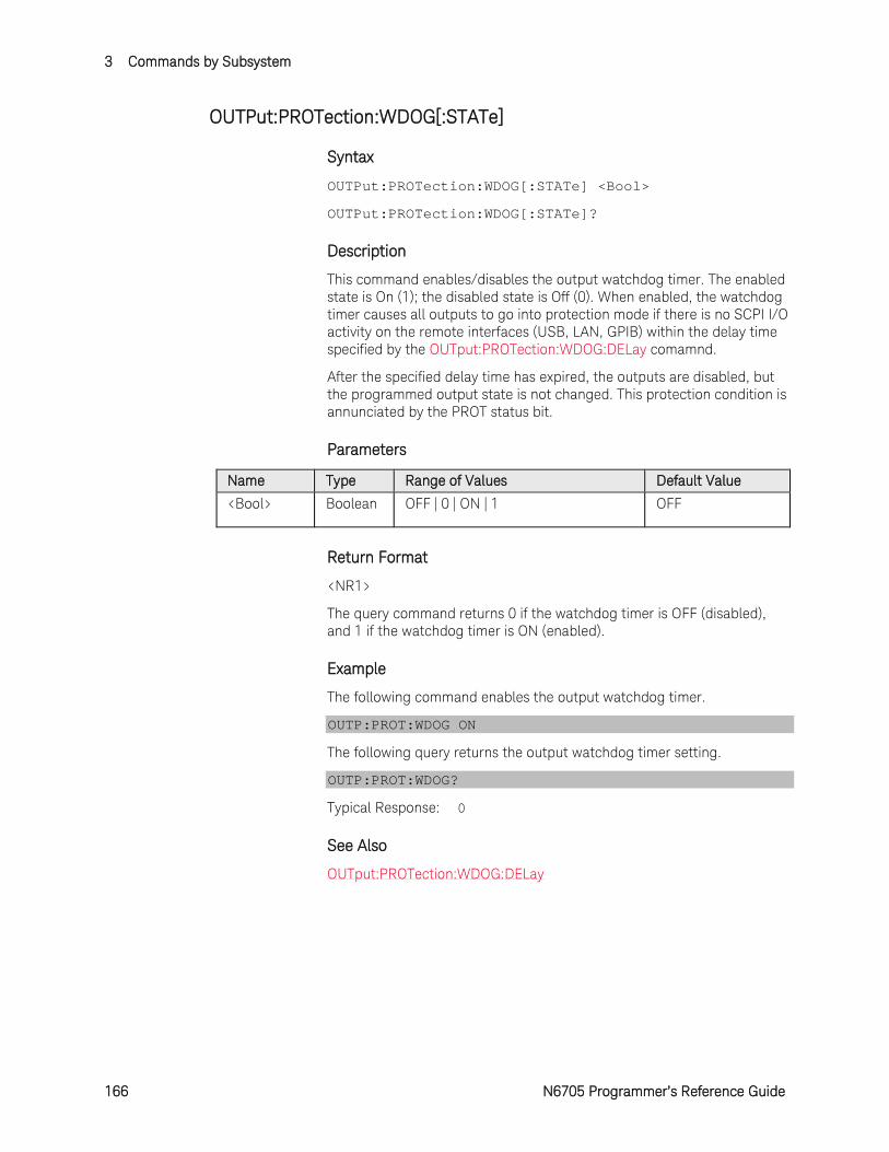
3 Commands by Subsystem
166 N6705 Programmer’s Reference Guide
OUTPut:PROTection:WDOG[:STATe]
Syntax
OUTPut:PROTection:WDOG[:STATe] <Bool>
OUTPut:PROTection:WDOG[:STATe]?
Description
This command enables/disables the output watchdog timer. The enabled state is On (1); the disabled state is Off (0). When enabled, the watchdog timer causes all outputs to go into protection mode if there is no SCPI I/O activity on the remote interfaces (USB, LAN, GPIB) within the delay time specified by the OUTput:PROTection:WDOG:DELay comamnd.
After the specified delay time has expired, the outputs are disabled, but the programmed output state is not changed. This protection condition is annunciated by the PROT status bit.
Parameters
Name Type Range of Values Default Value
<Bool> Boolean OFF | 0 | ON | 1 OFF
Return Format
<NR1>
The query command returns 0 if the watchdog timer is OFF (disabled), and 1 if the watchdog timer is ON (enabled).
Example
The following command enables the output watchdog timer.
OUTP:PROT:WDOG ON
The following query returns the output watchdog timer setting.
OUTP:PROT:WDOG?
Typical Response: 0
See Also
OUTput:PROTection:WDOG:DELay
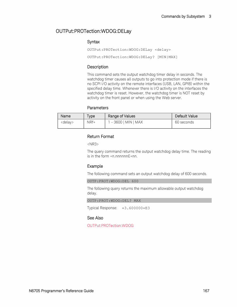
Commands by Subsystem 3
N6705 Programmer’s Reference Guide 167
OUTPut:PROTection:WDOG:DELay
Syntax
OUTPut:PROTection:WDOG:DELay <delay>
OUTPut:PROTection:WDOG:DELay? [MIN|MAX]
Description
This command sets the output watchdog timer delay in seconds. The watchdog timer causes all outputs to go into protection mode if there is no SCPI I/O activity on the remote interfaces (USB, LAN, GPIB) within the specified delay time. Whenever there is I/O activity on the interfaces the watchdog timer is reset. However, the watchdog timer is NOT reset by activity on the front panel or when using the Web server.
Parameters
Name Type Range of Values Default Value
<delay> NRf+ 1 - 3600 | MIN | MAX 60 seconds
Return Format
<NR3>
The query command returns the output watchdog delay time. The reading is in the form +n.nnnnnnE+nn.
Example
The following command sets an output watchdog delay of 600 seconds.
OUTP:PROT:WDOG:DEL 600
The following query returns the maximum allowable output watchdog delay.
OUTP:PROT:WDOG:DEL? MAX
Typical Response: +3.600000+E3
See Also
OUTPut:PROTection:WDOG
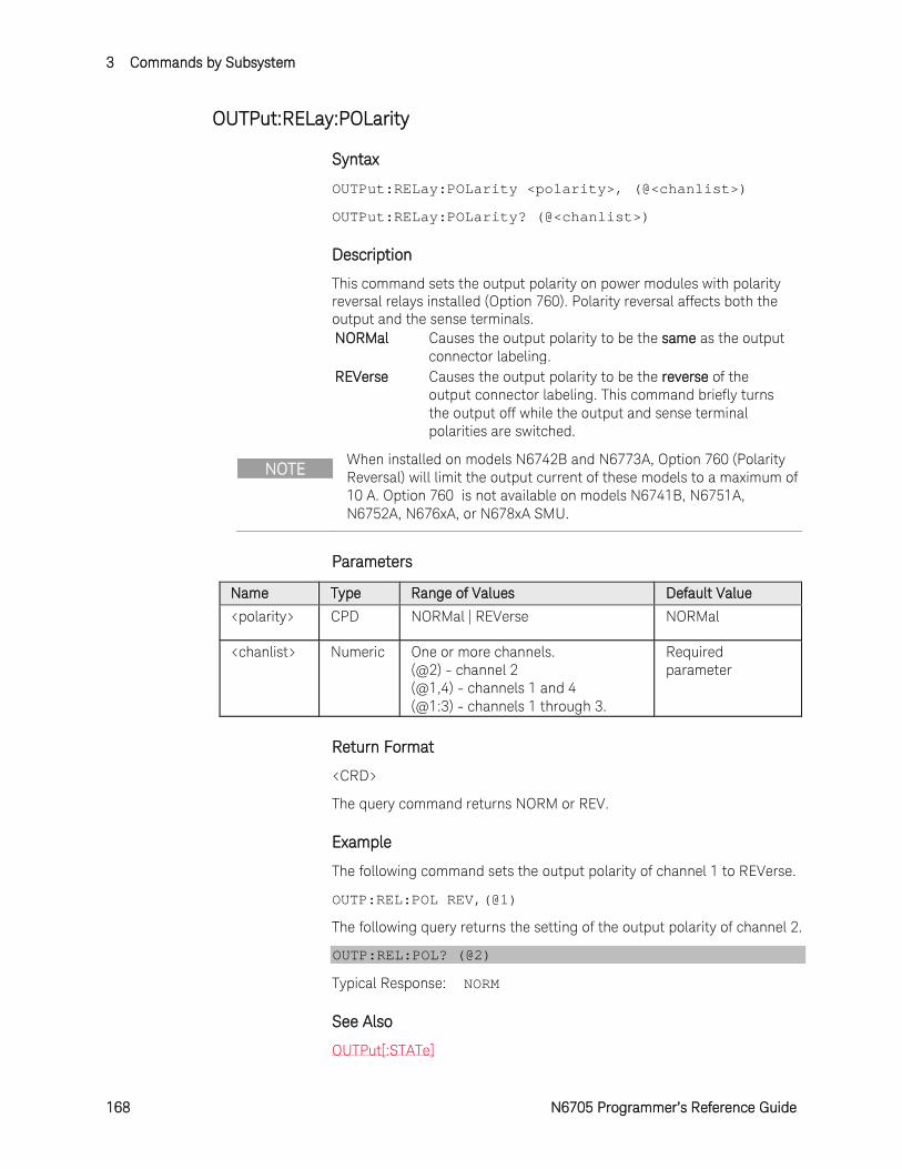
3 Commands by Subsystem
168 N6705 Programmer’s Reference Guide
OUTPut:RELay:POLarity
Syntax
OUTPut:RELay:POLarity <polarity>, (@<chanlist>)
OUTPut:RELay:POLarity? (@<chanlist>)
Description
This command sets the output polarity on power modules with polarity reversal relays installed (Option 760). Polarity reversal affects both the output and the sense terminals. NORMal Causes the output polarity to be the same as the output
connector labeling. REVerse Causes the output polarity to be the reverse of the
output connector labeling. This command briefly turns the output off while the output and sense terminal polarities are switched.
NOTE When installed on models N6742B and N6773A, Option 760 (Polarity Reversal) will limit the output current of these models to a maximum of 10 A. Option 760 is not available on models N6741B, N6751A, N6752A, N676xA, or N678xA SMU.
Parameters
Name Type Range of Values Default Value
<polarity> CPD NORMal | REVerse NORMal
<chanlist> Numeric One or more channels. (@2) - channel 2 (@1,4) - channels 1 and 4 (@1:3) - channels 1 through 3.
Required parameter
Return Format
<CRD>
The query command returns NORM or REV.
Example
The following command sets the output polarity of channel 1 to REVerse.
OUTP:REL:POL REV,(@1)
The following query returns the setting of the output polarity of channel 2.
OUTP:REL:POL? (@2)
Typical Response: NORM
See Also
OUTPut[:STATe]
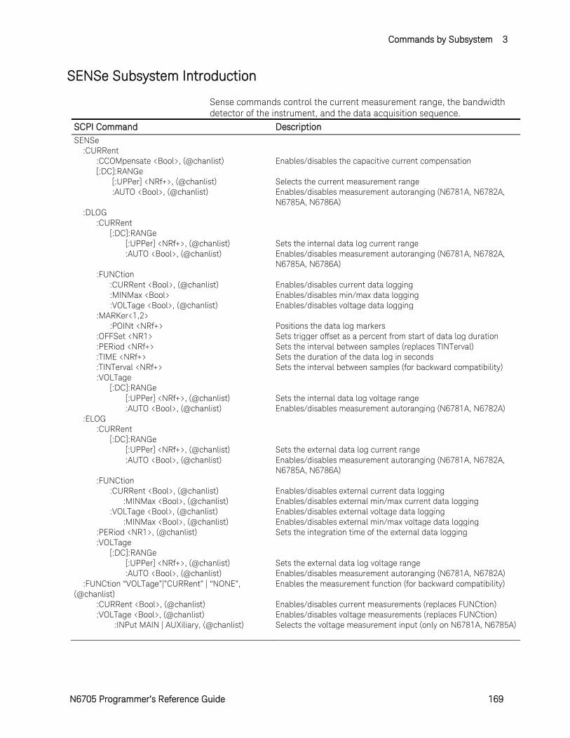
Commands by Subsystem 3
N6705 Programmer’s Reference Guide 169
SENSe Subsystem Introduction
Sense commands control the current measurement range, the bandwidth detector of the instrument, and the data acquisition sequence.
SCPI Command Description SENSe :CURRent :CCOMpensate <Bool>, (@chanlist) Enables/disables the capacitive current compensation [:DC]:RANGe [:UPPer] <NRf+>, (@chanlist) Selects the current measurement range :AUTO <Bool>, (@chanlist) Enables/disables measurement autoranging (N6781A, N6782A,
N6785A, N6786A) :DLOG :CURRent [:DC]:RANGe [:UPPer] <NRf+>, (@chanlist) Sets the internal data log current range :AUTO <Bool>, (@chanlist) Enables/disables measurement autoranging (N6781A, N6782A,
N6785A, N6786A) :FUNCtion :CURRent <Bool>, (@chanlist) Enables/disables current data logging :MINMax <Bool> Enables/disables min/max data logging :VOLTage <Bool>, (@chanlist) Enables/disables voltage data logging :MARKer<1,2> :POINt <NRf+> Positions the data log markers :OFFSet <NR1> Sets trigger offset as a percent from start of data log duration :PERiod <NRf+> Sets the interval between samples (replaces TINTerval) :TIME <NRf+> Sets the duration of the data log in seconds :TINTerval <NRf+> Sets the interval between samples (for backward compatibility) :VOLTage [:DC]:RANGe [:UPPer] <NRf+>, (@chanlist) Sets the internal data log voltage range :AUTO <Bool>, (@chanlist) Enables/disables measurement autoranging (N6781A, N6782A) :ELOG :CURRent [:DC]:RANGe [:UPPer] <NRf+>, (@chanlist) Sets the external data log current range :AUTO <Bool>, (@chanlist) Enables/disables measurement autoranging (N6781A, N6782A,
N6785A, N6786A) :FUNCtion :CURRent <Bool>, (@chanlist) Enables/disables external current data logging :MINMax <Bool>, (@chanlist) Enables/disables external min/max current data logging :VOLTage <Bool>, (@chanlist) Enables/disables external voltage data logging :MINMax <Bool>, (@chanlist) Enables/disables external min/max voltage data logging :PERiod <NR1>, (@chanlist) Sets the integration time of the external data logging :VOLTage [:DC]:RANGe [:UPPer] <NRf+>, (@chanlist) Sets the external data log voltage range :AUTO <Bool>, (@chanlist) Enables/disables measurement autoranging (N6781A, N6782A) :FUNCtion “VOLTage”|”CURRent” | “NONE”, (@chanlist)
Enables the measurement function (for backward compatibility)
:CURRent <Bool>, (@chanlist) Enables/disables current measurements (replaces FUNCtion) :VOLTage <Bool>, (@chanlist) Enables/disables voltage measurements (replaces FUNCtion) :INPut MAIN | AUXiliary, (@chanlist) Selects the voltage measurement input (only on N6781A, N6785A)
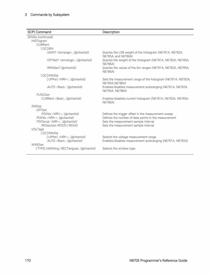
3 Commands by Subsystem
170 N6705 Programmer’s Reference Guide
SCPI Command Description SENSe (continued) :HISTogram :CURRent [:DC]:BIN :GAIN? <binrange>, (@chanlist) Queries the LSB weight of the histogram (N6781A, N6782A,
N6785A, and N6786A) :OFFSet? <binrange>, (@chanlist) Queries the weight of the histogram (N6781A, N6782A, N6785A,
N6786A) :RANGes? (@chanlist) Queries the values of the bin ranges (N6781A, N6782A, N6785A,
N6786A) [:DC]:RANGe [:UPPer] <NRf+>, (@chanlist) Sets the measurement range of the histogram (N6781A, N6782A,
N6785A,N6786A) :AUTO <Bool>, (@chanlist) Enables/disables measurement autoranging (N6781A, N6782A,
N6785A, N6786A) :FUNCtion :CURRent <Bool>, (@chanlist) Enables/disables current histogram (N6781A, N6782A, N6785A,
N6786A) :SWEep :OFFSet :POINts <NRf+>, (@chanlist) Defines the trigger offset in the measurement sweep :POINts <NRf+>, (@chanlist) Defines the number of data points in the measurement :TINTerval <NRf+>, (@chanlist) Sets the measurement sample interval :RESolution RES20 | RES40 Sets the measurement sample interval :VOLTage [:DC]:RANGe [:UPPer] <NRf+>, (@chanlist) Selects the voltage measurement range :AUTO <Bool>, (@chanlist) Enables/disables measurement autoranging (N6781A, N6782A) :WINDow [:TYPE] HANNing | RECTangular, (@chanlist) Selects the window type
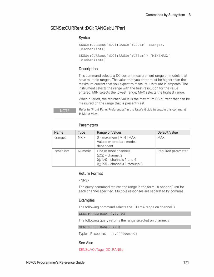
Commands by Subsystem 3
N6705 Programmer’s Reference Guide 171
SENSe:CURRent[:DC]:RANGe[:UPPer]
Syntax
SENSe:CURRent[:DC]:RANGe[:UPPer] <range>, (@<chanlist>)
SENSe:CURRent[:DC]:RANGe[:UPPer]? [MIN|MAX,] (@<chanlist>)
Description
This command selects a DC current measurement range on models that have multiple ranges. The value that you enter must be higher than the maximum current that you expect to measure. Units are in amperes. The instrument selects the range with the best resolution for the value entered. MIN selects the lowest range; MAX selects the highest range.
When queried, the returned value is the maximum DC current that can be measured on the range that is presently set.
NOTE Refer to “Front Panel Preferences” in the User’s Guide to enable this command in Meter View.
Parameters
Name Type Range of Values Default Value <range> NRf+ 0 - maximum | MIN | MAX
Values entered are model dependent.
MAX
<chanlist> Numeric One or more channels. (@2) - channel 2 (@1,4) - channels 1 and 4 (@1:3) - channels 1 through 3.
Required parameter
Return Format
<NR3>
The query command returns the range in the form +n.nnnnnnE+nn for each channel specified. Multiple responses are separated by commas.
Examples
The following command selects the 100 mA range on channel 3.
SENS:CURR:RANG 0.1,(@3)
The following query returns the range selected on channel 3.
SENS:CURR:RANG? (@3)
Typical Response: +1.000000E-01
See Also
SENSe:VOLTage[:DC]:RANGe
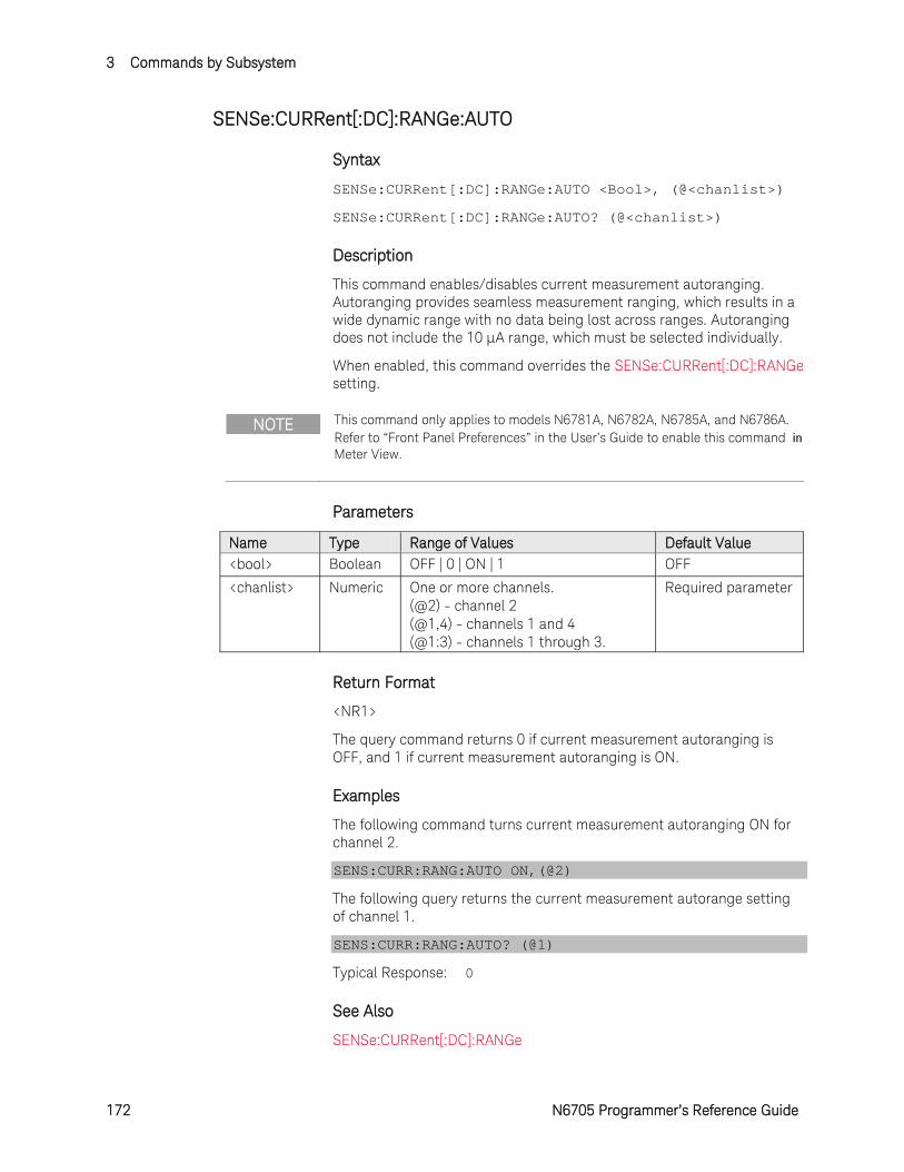
3 Commands by Subsystem
172 N6705 Programmer’s Reference Guide
SENSe:CURRent[:DC]:RANGe:AUTO
Syntax
SENSe:CURRent[:DC]:RANGe:AUTO <Bool>, (@<chanlist>)
SENSe:CURRent[:DC]:RANGe:AUTO? (@<chanlist>)
Description
This command enables/disables current measurement autoranging. Autoranging provides seamless measurement ranging, which results in a wide dynamic range with no data being lost across ranges. Autoranging does not include the 10 μA range, which must be selected individually.
When enabled, this command overrides the SENSe:CURRent[:DC]:RANGe setting.
NOTE This command only applies to models N6781A, N6782A, N6785A, and N6786A. Refer to “Front Panel Preferences” in the User’s Guide to enable this command in Meter View.
Parameters
Name Type Range of Values Default Value <bool> Boolean OFF | 0 | ON | 1 OFF
<chanlist> Numeric One or more channels. (@2) - channel 2 (@1,4) - channels 1 and 4 (@1:3) - channels 1 through 3.
Required parameter
Return Format
<NR1>
The query command returns 0 if current measurement autoranging is OFF, and 1 if current measurement autoranging is ON.
Examples
The following command turns current measurement autoranging ON for channel 2.
SENS:CURR:RANG:AUTO ON,(@2)
The following query returns the current measurement autorange setting of channel 1.
SENS:CURR:RANG:AUTO? (@1)
Typical Response: 0
See Also
SENSe:CURRent[:DC]:RANGe
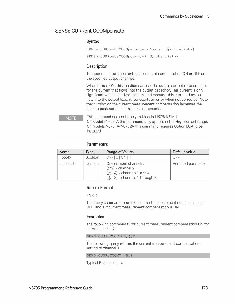
Commands by Subsystem 3
N6705 Programmer’s Reference Guide 173
SENSe:CURRent:CCOMpensate
Syntax
SENSe:CURRent:CCOMpensate <Bool>, (@<chanlist>)
SENSe:CURRent:CCOMpensate? (@<chanlist>)
Description
This command turns current measurement compensation ON or OFF on the specified output channel.
When turned ON, this function corrects the output current measurement for the current that flows into the output capacitor. This current is only significant when high dv/dt occurs, and because this current does not flow into the output load, it represents an error when not corrected. Note that turning on the current measurement compensation increases the peak to peak noise in current measurements.
NOTE This command does not apply to Models N678xA SMU. On Models N676xA this command only applies in the High current range. On Models N6751A/N6752A this command requires Option LGA to be installed.
Parameters
Name Type Range of Values Default Value <bool> Boolean OFF | 0 | ON | 1 OFF
<chanlist> Numeric One or more channels. (@2) - channel 2 (@1,4) - channels 1 and 4 (@1:3) - channels 1 through 3.
Required parameter
Return Format
<NR1>
The query command returns 0 if current measurement compensation is OFF, and 1 if current measurement compensation is ON.
Examples
The following command turns current measurement compensation ON for output channel 2.
SENS:CURR:CCOM ON,(@2)
The following query returns the current measurement compensation setting of channel 1.
SENS:CURR:CCOM? (@1)
Typical Response: 0
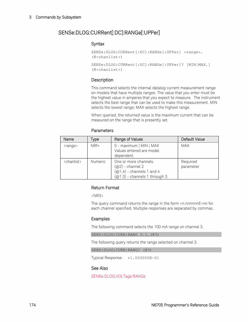
3 Commands by Subsystem
174 N6705 Programmer’s Reference Guide
SENSe:DLOG:CURRent[:DC]:RANGe[:UPPer]
Syntax
SENSe:DLOG:CURRent[:DC]:RANGe[:UPPer] <range>, (@<chanlist>)
SENSe:DLOG:CURRent[:DC]:RANGe[:UPPer]? [MIN|MAX,] (@<chanlist>)
Description
This command selects the internal datalog current measurement range on models that have multiple ranges. The value that you enter must be the highest value in amperes that you expect to measure. The instrument selects the best range that can be used to make this measurement. MIN selects the lowest range; MAX selects the highest range.
When queried, the returned value is the maximum current that can be measured on the range that is presently set.
Parameters
Name Type Range of Values Default Value <range> NRf+ 0 - maximum | MIN | MAX
Values entered are model dependent.
MAX
<chanlist> Numeric One or more channels. (@2) - channel 2 (@1,4) - channels 1 and 4 (@1:3) - channels 1 through 3.
Required parameter
Return Format
<NR3>
The query command returns the range in the form +n.nnnnnnE+nn for each channel specified. Multiple responses are separated by commas.
Examples
The following command selects the 100 mA range on channel 3.
SENS:DLOG:CURR:RANG 0.1,(@3)
The following query returns the range selected on channel 3.
SENS:DLOG:CURR:RANG? (@3)
Typical Response: +1.000000E-01
See Also
SENSe:DLOG:VOLTage:RANGe
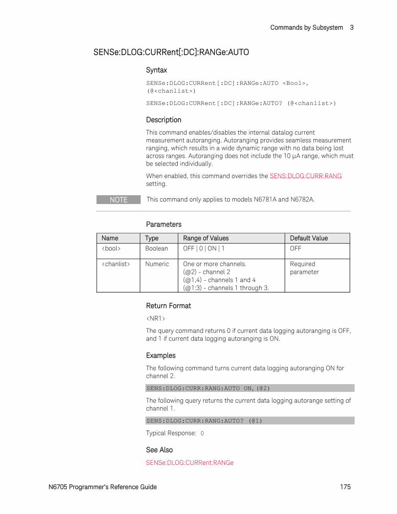
Commands by Subsystem 3
N6705 Programmer’s Reference Guide 175
SENSe:DLOG:CURRent[:DC]:RANGe:AUTO
Syntax
SENSe:DLOG:CURRent[:DC]:RANGe:AUTO <Bool>, (@<chanlist>)
SENSe:DLOG:CURRent[:DC]:RANGe:AUTO? (@<chanlist>)
Description
This command enables/disables the internal datalog current measurement autoranging. Autoranging provides seamless measurement ranging, which results in a wide dynamic range with no data being lost across ranges. Autoranging does not include the 10 μA range, which must be selected individually.
When enabled, this command overrides the SENS:DLOG:CURR:RANG setting.
NOTE This command only applies to models N6781A and N6782A.
Parameters
Name Type Range of Values Default Value <bool> Boolean OFF | 0 | ON | 1 OFF
<chanlist> Numeric One or more channels. (@2) - channel 2 (@1,4) - channels 1 and 4 (@1:3) - channels 1 through 3.
Required parameter
Return Format
<NR1>
The query command returns 0 if current data logging autoranging is OFF, and 1 if current data logging autoranging is ON.
Examples
The following command turns current data logging autoranging ON for channel 2.
SENS:DLOG:CURR:RANG:AUTO ON,(@2)
The following query returns the current data logging autorange setting of channel 1.
SENS:DLOG:CURR:RANG:AUTO? (@1)
Typical Response: 0
See Also
SENSe:DLOG:CURRent:RANGe

3 Commands by Subsystem
176 N6705 Programmer’s Reference Guide
SENSe:DLOG:FUNCtion:CURRent
Syntax
SENSe:DLOG:FUNCtion:CURRent <Bool>, (@<chanlist>)
SENSe:DLOG:FUNCtion:CURRent? (@<chanlist>)
Description
This command turns current data logging ON or OFF on the specified output channel.
Parameters
Name Type Range of Values Default Value <bool> Boolean OFF | 0 | ON | 1 OFF
<chanlist> Numeric One or more channels. (@2) - channel 2 (@1,4) - channels 1 and 4 (@1:3) - channels 1 through 3.
Required parameter
Return Format
<NR1>
The query command returns 0 if current data logging is OFF, and 1 if current data logging is ON.
Examples
The following command turns current data logging ON for output channel 2.
SENS:DLOG:FUNC:CURR ON,(@2)
The following query returns the current data logging setting of channel 1.
SENS:DLOG:FUNC:CURR? (@1)
Typical Response: 0
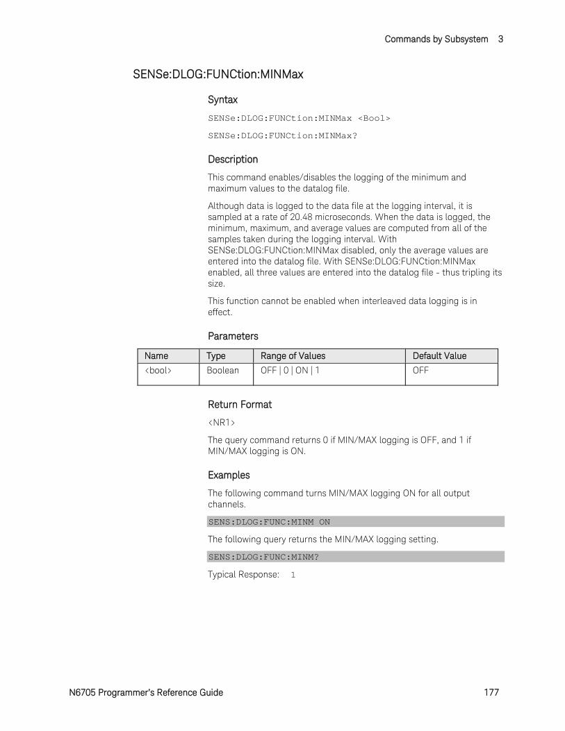
Commands by Subsystem 3
N6705 Programmer’s Reference Guide 177
SENSe:DLOG:FUNCtion:MINMax
Syntax
SENSe:DLOG:FUNCtion:MINMax <Bool>
SENSe:DLOG:FUNCtion:MINMax?
Description
This command enables/disables the logging of the minimum and maximum values to the datalog file.
Although data is logged to the data file at the logging interval, it is sampled at a rate of 20.48 microseconds. When the data is logged, the minimum, maximum, and average values are computed from all of the samples taken during the logging interval. With SENSe:DLOG:FUNCtion:MINMax disabled, only the average values are entered into the datalog file. With SENSe:DLOG:FUNCtion:MINMax enabled, all three values are entered into the datalog file - thus tripling its size.
This function cannot be enabled when interleaved data logging is in effect.
Parameters
Name Type Range of Values Default Value <bool> Boolean OFF | 0 | ON | 1 OFF
Return Format
<NR1>
The query command returns 0 if MIN/MAX logging is OFF, and 1 if MIN/MAX logging is ON.
Examples
The following command turns MIN/MAX logging ON for all output channels.
SENS:DLOG:FUNC:MINM ON
The following query returns the MIN/MAX logging setting.
SENS:DLOG:FUNC:MINM?
Typical Response: 1
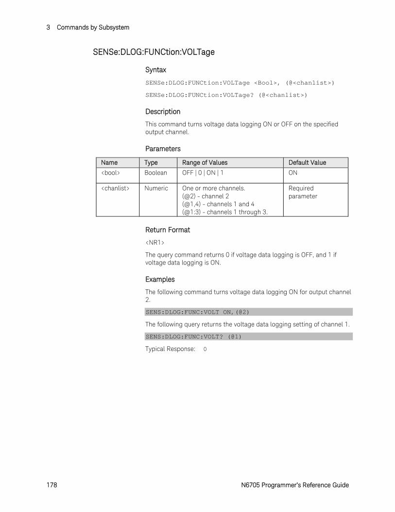
3 Commands by Subsystem
178 N6705 Programmer’s Reference Guide
SENSe:DLOG:FUNCtion:VOLTage
Syntax
SENSe:DLOG:FUNCtion:VOLTage <Bool>, (@<chanlist>)
SENSe:DLOG:FUNCtion:VOLTage? (@<chanlist>)
Description
This command turns voltage data logging ON or OFF on the specified output channel.
Parameters
Name Type Range of Values Default Value <bool> Boolean OFF | 0 | ON | 1 ON
<chanlist> Numeric One or more channels. (@2) - channel 2 (@1,4) - channels 1 and 4 (@1:3) - channels 1 through 3.
Required parameter
Return Format
<NR1>
The query command returns 0 if voltage data logging is OFF, and 1 if voltage data logging is ON.
Examples
The following command turns voltage data logging ON for output channel 2.
SENS:DLOG:FUNC:VOLT ON,(@2)
The following query returns the voltage data logging setting of channel 1.
SENS:DLOG:FUNC:VOLT? (@1)
Typical Response: 0
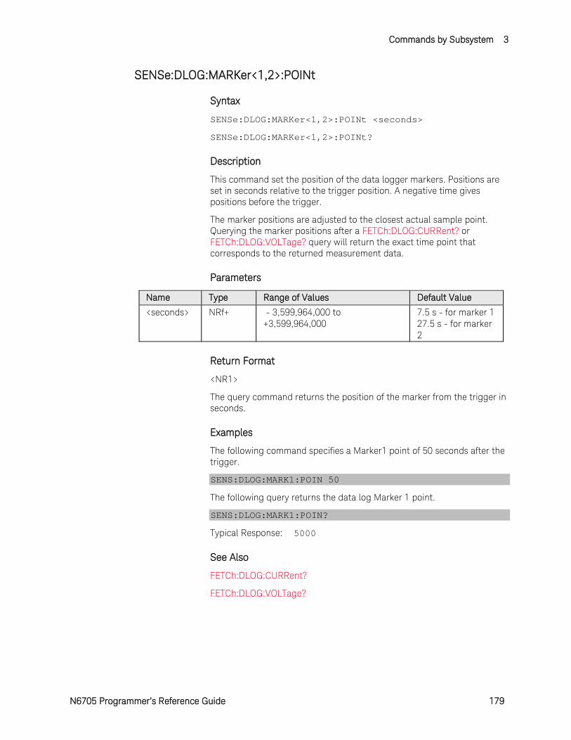
Commands by Subsystem 3
N6705 Programmer’s Reference Guide 179
SENSe:DLOG:MARKer<1,2>:POINt
Syntax
SENSe:DLOG:MARKer<1,2>:POINt <seconds>
SENSe:DLOG:MARKer<1,2>:POINt?
Description
This command set the position of the data logger markers. Positions are set in seconds relative to the trigger position. A negative time gives positions before the trigger.
The marker positions are adjusted to the closest actual sample point. Querying the marker positions after a FETCh:DLOG:CURRent? or FETCh:DLOG:VOLTage? query will return the exact time point that corresponds to the returned measurement data.
Parameters
Name Type Range of Values Default Value <seconds> NRf+ - 3,599,964,000 to
+3,599,964,000 7.5 s - for marker 1 27.5 s - for marker 2
Return Format
<NR1>
The query command returns the position of the marker from the trigger in seconds.
Examples
The following command specifies a Marker1 point of 50 seconds after the trigger.
SENS:DLOG:MARK1:POIN 50
The following query returns the data log Marker 1 point.
SENS:DLOG:MARK1:POIN?
Typical Response: 5000
See Also
FETCh:DLOG:CURRent?
FETCh:DLOG:VOLTage?
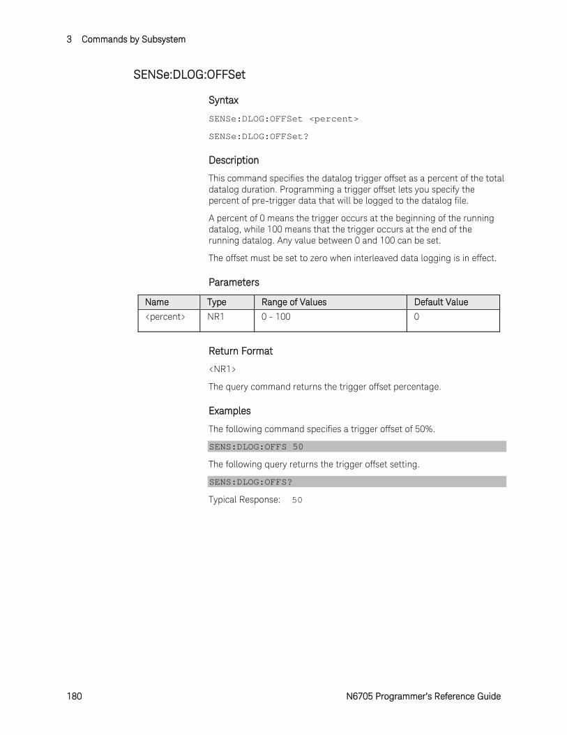
3 Commands by Subsystem
180 N6705 Programmer’s Reference Guide
SENSe:DLOG:OFFSet
Syntax
SENSe:DLOG:OFFSet <percent>
SENSe:DLOG:OFFSet?
Description
This command specifies the datalog trigger offset as a percent of the total datalog duration. Programming a trigger offset lets you specify the percent of pre-trigger data that will be logged to the datalog file.
A percent of 0 means the trigger occurs at the beginning of the running datalog, while 100 means that the trigger occurs at the end of the running datalog. Any value between 0 and 100 can be set.
The offset must be set to zero when interleaved data logging is in effect.
Parameters
Name Type Range of Values Default Value <percent> NR1 0 - 100 0
Return Format
<NR1>
The query command returns the trigger offset percentage.
Examples
The following command specifies a trigger offset of 50%.
SENS:DLOG:OFFS 50
The following query returns the trigger offset setting.
SENS:DLOG:OFFS?
Typical Response: 50
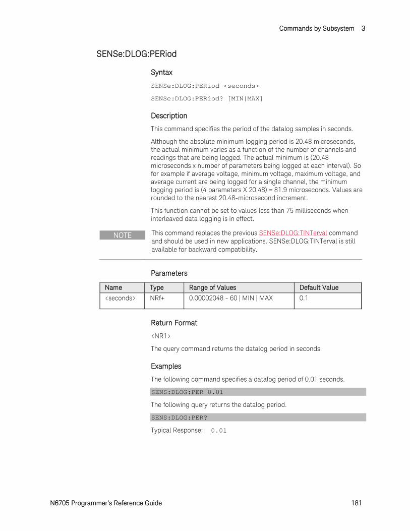
Commands by Subsystem 3
N6705 Programmer’s Reference Guide 181
SENSe:DLOG:PERiod
Syntax
SENSe:DLOG:PERiod <seconds>
SENSe:DLOG:PERiod? [MIN|MAX]
Description
This command specifies the period of the datalog samples in seconds.
Although the absolute minimum logging period is 20.48 microseconds, the actual minimum varies as a function of the number of channels and readings that are being logged. The actual minimum is (20.48 microseconds x number of parameters being logged at each interval). So for example if average voltage, minimum voltage, maximum voltage, and average current are being logged for a single channel, the minimum logging period is (4 parameters X 20.48) = 81.9 microseconds. Values are rounded to the nearest 20.48-microsecond increment.
This function cannot be set to values less than 75 milliseconds when interleaved data logging is in effect.
NOTE This command replaces the previous SENSe:DLOG:TINTerval command and should be used in new applications. SENSe:DLOG:TINTerval is still available for backward compatibility.
Parameters
Name Type Range of Values Default Value <seconds> NRf+ 0.00002048 - 60 | MIN | MAX 0.1
Return Format
<NR1>
The query command returns the datalog period in seconds.
Examples
The following command specifies a datalog period of 0.01 seconds.
SENS:DLOG:PER 0.01
The following query returns the datalog period.
SENS:DLOG:PER?
Typical Response: 0.01
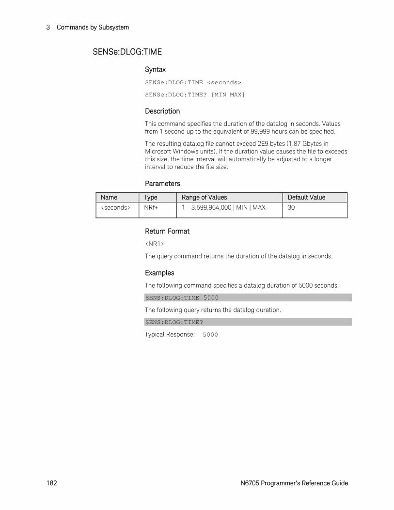
3 Commands by Subsystem
182 N6705 Programmer’s Reference Guide
SENSe:DLOG:TIME
Syntax
SENSe:DLOG:TIME <seconds>
SENSe:DLOG:TIME? [MIN|MAX]
Description
This command specifies the duration of the datalog in seconds. Values from 1 second up to the equivalent of 99,999 hours can be specified.
The resulting datalog file cannot exceed 2E9 bytes (1.87 Gbytes in Microsoft Windows units). If the duration value causes the file to exceeds this size, the time interval will automatically be adjusted to a longer interval to reduce the file size.
Parameters
Name Type Range of Values Default Value <seconds> NRf+ 1 - 3,599,964,000 | MIN | MAX 30
Return Format
<NR1>
The query command returns the duration of the datalog in seconds.
Examples
The following command specifies a datalog duration of 5000 seconds.
SENS:DLOG:TIME 5000
The following query returns the datalog duration.
SENS:DLOG:TIME?
Typical Response: 5000
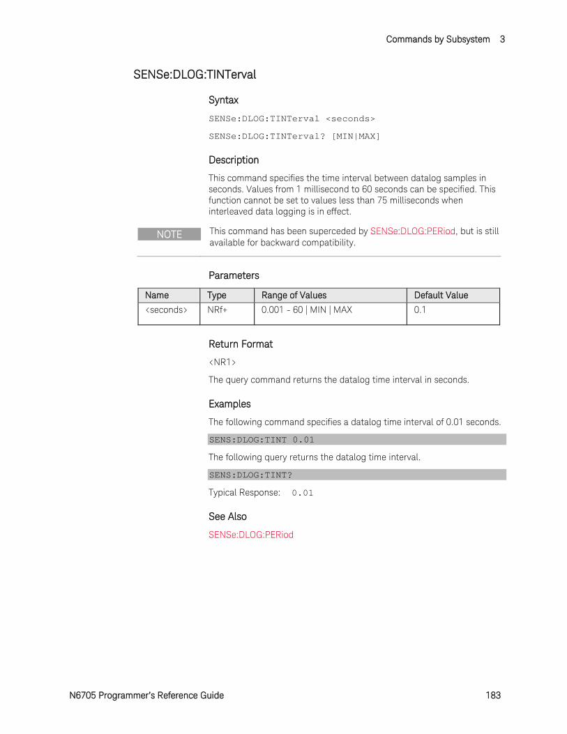
Commands by Subsystem 3
N6705 Programmer’s Reference Guide 183
SENSe:DLOG:TINTerval
Syntax
SENSe:DLOG:TINTerval <seconds>
SENSe:DLOG:TINTerval? [MIN|MAX]
Description
This command specifies the time interval between datalog samples in seconds. Values from 1 millisecond to 60 seconds can be specified. This function cannot be set to values less than 75 milliseconds when interleaved data logging is in effect.
NOTE This command has been superceded by SENSe:DLOG:PERiod, but is still available for backward compatibility.
Parameters
Name Type Range of Values Default Value <seconds> NRf+ 0.001 - 60 | MIN | MAX 0.1
Return Format
<NR1>
The query command returns the datalog time interval in seconds.
Examples
The following command specifies a datalog time interval of 0.01 seconds.
SENS:DLOG:TINT 0.01
The following query returns the datalog time interval.
SENS:DLOG:TINT?
Typical Response: 0.01
See Also
SENSe:DLOG:PERiod

3 Commands by Subsystem
184 N6705 Programmer’s Reference Guide
SENSe:DLOG:VOLTage[:DC]:RANGe[:UPPer]
Syntax
SENSe:DLOG:VOLTage[:DC]:RANGe[:UPPer] <range>, (@<chanlist>)
SENSe:DLOG:VOLTage[:DC]:RANGe[:UPPer]? [MIN|MAX,] (@<chanlist>)
Description
This command selects the internal datalog voltage measurement range on models that have multiple ranges. The value that you enter must be the highest value in volts that you expect to measure. The instrument selects the best range that can be used to make this measurement. MIN selects the lowest range; MAX selects the highest range.
When queried, the returned value is the maximum voltage that can be measured on the range that is presently set.
Parameters
Name Type Range of Values Default Value <range> NRf+ 0 - maximum | MIN | MAX
Values entered are model dependent.
MAX
<chanlist> Numeric One or more channels. (@2) - channel 2 (@1,4) - channels 1 and 4 (@1:3) - channels 1 through 3.
Required parameter
Return Format
<NR3>
The query command returns the range in the form +n.nnnnnnE+nn for each channel specified. Multiple responses are separated by commas.
Examples
The following command selects the 5 V range on channel 3.
SENS:DLOG:VOLT:RANG 5,(@3)
The following query returns the range selected on channel 1.
SENS:DLOG:VOLT:RANG? (@1)
Typical Response: +5.500000E+01
See Also
SENSe:DLOG:CURRent:RANGe
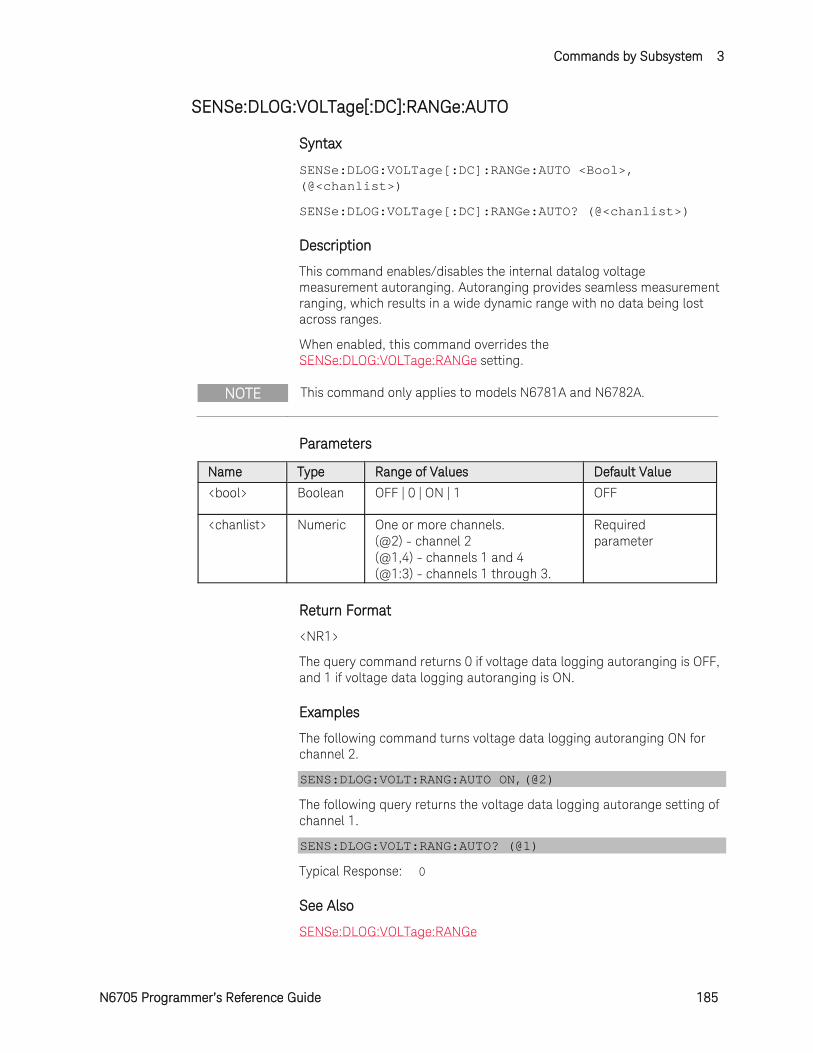
Commands by Subsystem 3
N6705 Programmer’s Reference Guide 185
SENSe:DLOG:VOLTage[:DC]:RANGe:AUTO
Syntax
SENSe:DLOG:VOLTage[:DC]:RANGe:AUTO <Bool>, (@<chanlist>)
SENSe:DLOG:VOLTage[:DC]:RANGe:AUTO? (@<chanlist>)
Description
This command enables/disables the internal datalog voltage measurement autoranging. Autoranging provides seamless measurement ranging, which results in a wide dynamic range with no data being lost across ranges.
When enabled, this command overrides the SENSe:DLOG:VOLTage:RANGe setting.
NOTE This command only applies to models N6781A and N6782A.
Parameters
Name Type Range of Values Default Value <bool> Boolean OFF | 0 | ON | 1 OFF
<chanlist> Numeric One or more channels. (@2) - channel 2 (@1,4) - channels 1 and 4 (@1:3) - channels 1 through 3.
Required parameter
Return Format
<NR1>
The query command returns 0 if voltage data logging autoranging is OFF, and 1 if voltage data logging autoranging is ON.
Examples
The following command turns voltage data logging autoranging ON for channel 2.
SENS:DLOG:VOLT:RANG:AUTO ON,(@2)
The following query returns the voltage data logging autorange setting of channel 1.
SENS:DLOG:VOLT:RANG:AUTO? (@1)
Typical Response: 0
See Also
SENSe:DLOG:VOLTage:RANGe

3 Commands by Subsystem
186 N6705 Programmer’s Reference Guide
SENSe:ELOG:CURRent[:DC]:RANGe[:UPPer]
Syntax
SENSe:ELOG:CURRent[:DC]:RANGe[:UPPer] <range>, (@<chanlist>)
SENSe:ELOG:CURRent[:DC]:RANGe[:UPPer]? [MIN|MAX,] (@<chanlist>)
Description
This command selects the external datalog current measurement range on models that have multiple ranges. The value that you enter must be the highest value in amperes that you expect to measure. The instrument selects the best range that can be used to make this measurement. MIN selects the lowest range; MAX selects the highest range.
When queried, the returned value is the maximum current that can be measured on the range that is presently set.
Parameters
Name Type Range of Values Default Value <range> NRf+ 0 - maximum | MIN | MAX
Values entered are model dependent.
MAX
<chanlist> Numeric One or more channels. (@2) - channel 2 (@1,4) - channels 1 and 4 (@1:3) - channels 1 through 3.
Required parameter
Return Format
<NR3>
The query command returns the range in the form +n.nnnnnnE+nn for each channel specified. Multiple responses are separated by commas.
Examples
The following command selects the 100 mA range on channel 3.
SENS:ELOG:CURR:RANG 0.1,(@3)
The following query returns the range selected on channel 3.
SENS:ELOG:CURR:RANG? (@3)
Typical Response: +1.000000E-01
See Also
SENSe:ELOG:VOLTage:RANGe
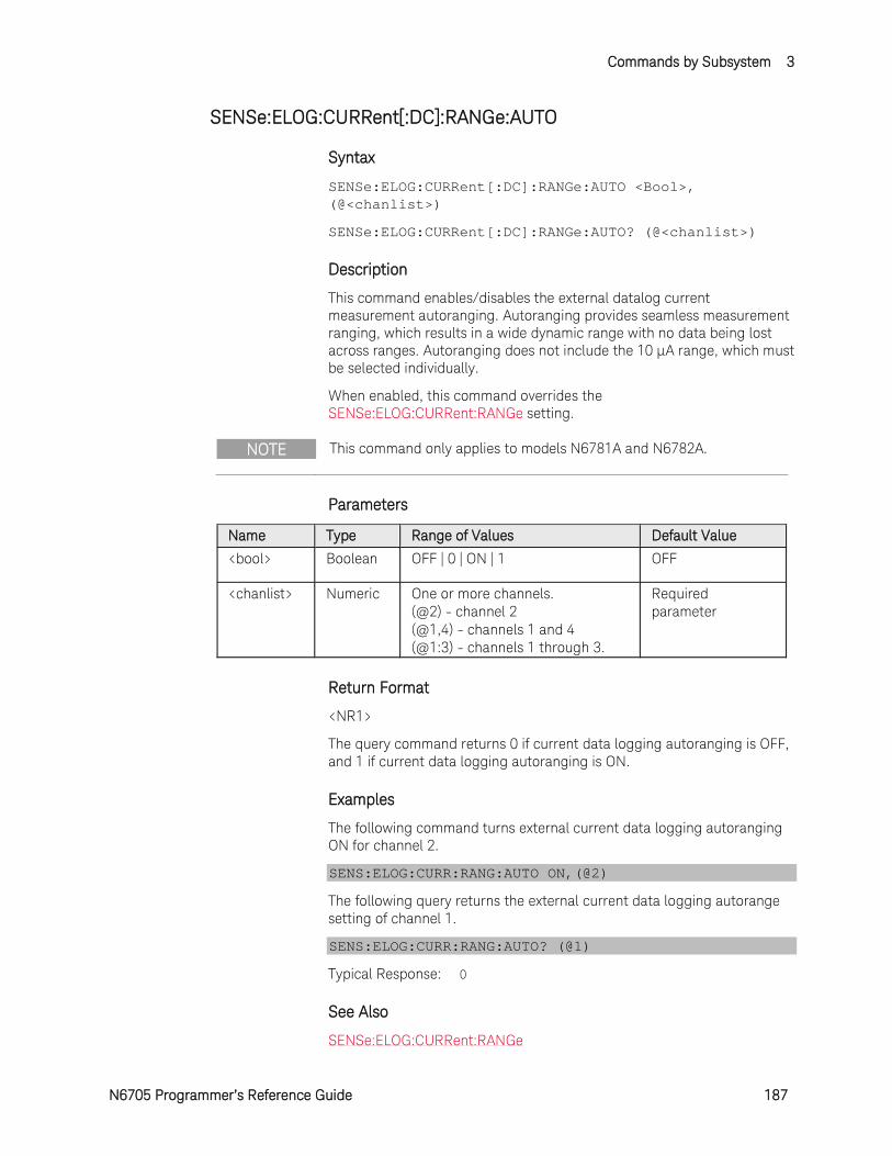
Commands by Subsystem 3
N6705 Programmer’s Reference Guide 187
SENSe:ELOG:CURRent[:DC]:RANGe:AUTO
Syntax
SENSe:ELOG:CURRent[:DC]:RANGe:AUTO <Bool>, (@<chanlist>)
SENSe:ELOG:CURRent[:DC]:RANGe:AUTO? (@<chanlist>)
Description
This command enables/disables the external datalog current measurement autoranging. Autoranging provides seamless measurement ranging, which results in a wide dynamic range with no data being lost across ranges. Autoranging does not include the 10 μA range, which must be selected individually.
When enabled, this command overrides the SENSe:ELOG:CURRent:RANGe setting.
NOTE This command only applies to models N6781A and N6782A.
Parameters
Name Type Range of Values Default Value <bool> Boolean OFF | 0 | ON | 1 OFF
<chanlist> Numeric One or more channels. (@2) - channel 2 (@1,4) - channels 1 and 4 (@1:3) - channels 1 through 3.
Required parameter
Return Format
<NR1>
The query command returns 0 if current data logging autoranging is OFF, and 1 if current data logging autoranging is ON.
Examples
The following command turns external current data logging autoranging ON for channel 2.
SENS:ELOG:CURR:RANG:AUTO ON,(@2)
The following query returns the external current data logging autorange setting of channel 1.
SENS:ELOG:CURR:RANG:AUTO? (@1)
Typical Response: 0
See Also
SENSe:ELOG:CURRent:RANGe
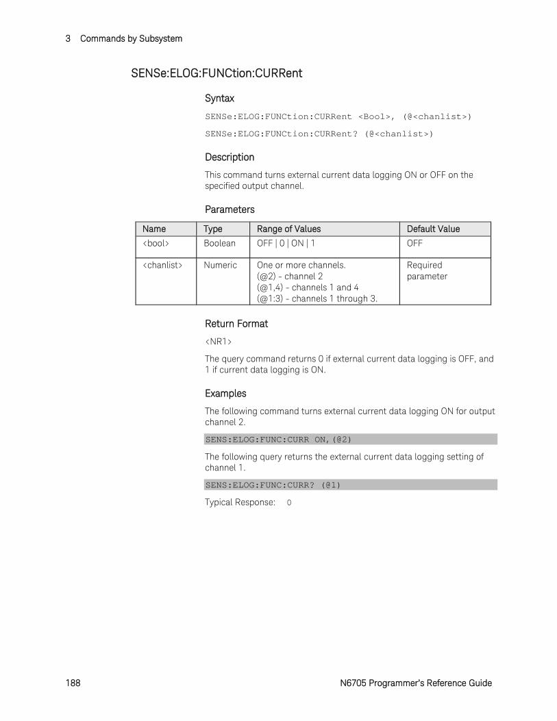
3 Commands by Subsystem
188 N6705 Programmer’s Reference Guide
SENSe:ELOG:FUNCtion:CURRent
Syntax
SENSe:ELOG:FUNCtion:CURRent <Bool>, (@<chanlist>)
SENSe:ELOG:FUNCtion:CURRent? (@<chanlist>)
Description
This command turns external current data logging ON or OFF on the specified output channel.
Parameters
Name Type Range of Values Default Value <bool> Boolean OFF | 0 | ON | 1 OFF
<chanlist> Numeric One or more channels. (@2) - channel 2 (@1,4) - channels 1 and 4 (@1:3) - channels 1 through 3.
Required parameter
Return Format
<NR1>
The query command returns 0 if external current data logging is OFF, and 1 if current data logging is ON.
Examples
The following command turns external current data logging ON for output channel 2.
SENS:ELOG:FUNC:CURR ON,(@2)
The following query returns the external current data logging setting of channel 1.
SENS:ELOG:FUNC:CURR? (@1)
Typical Response: 0

Commands by Subsystem 3
N6705 Programmer’s Reference Guide 189
SENSe:ELOG:FUNCtion:CURRent:MINMax
Syntax
SENSe:ELOG:FUNCtion:CURRent:MINMax <Bool>, (@<chanlist>)
SENSe:ELOG:FUNCtion:CURRent:MINMax? (@<chanlist>)
Description
This command turns external current data logging of the minimum and maximum current measurements ON or OFF on the specified output channel.
Parameters
Name Type Range of Values Default Value <bool> Boolean OFF | 0 | ON | 1 OFF
<chanlist> Numeric One or more channels. (@2) - channel 2 (@1,4) - channels 1 and 4 (@1:3) - channels 1 through 3.
Required parameter
Return Format
<NR1>
The query command returns 0 if external minimum and maximum current measurements is OFF, and 1 if minimum and maximum current measurements is ON.
Examples
The following command turns external minimum and maximum current measurements ON for output channel 2.
SENS:ELOG:FUNC:CURR:MINM ON,(@2)
The following query returns the external minimum and maximum current measurements setting of channel 1.
SENS:ELOG:FUNC:CURR:MINM? (@1)
Typical Response: 0

3 Commands by Subsystem
190 N6705 Programmer’s Reference Guide
SENSe:ELOG:FUNCtion:VOLTage
Syntax
SENSe:ELOG:FUNCtion:VOLTage <Bool>, (@<chanlist>)
SENSe:ELOG:FUNCtion:VOLTage? (@<chanlist>)
Description
This command turns external voltage data logging ON or OFF on the specified output channel.
Parameters
Name Type Range of Values Default Value <bool> Boolean OFF | 0 | ON | 1 ON
<chanlist> Numeric One or more channels. (@2) - channel 2 (@1,4) - channels 1 and 4 (@1:3) - channels 1 through 3.
Required parameter
Return Format
<NR1>
The query command returns 0 if external voltage data logging is OFF, and 1 if voltage data logging is ON.
Examples
The following command turns external voltage data logging ON for output channel 2.
SENS:ELOG:FUNC:VOLT ON,(@2)
The following query returns the external voltage data logging setting of channel 1.
SENS:ELOG:FUNC:VOLT? (@1)
Typical Response: 0
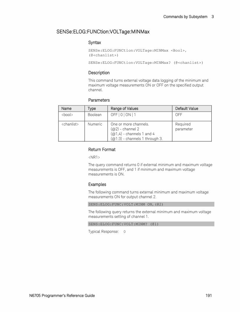
Commands by Subsystem 3
N6705 Programmer’s Reference Guide 191
SENSe:ELOG:FUNCtion:VOLTage:MINMax
Syntax
SENSe:ELOG:FUNCtion:VOLTage:MINMax <Bool>, (@<chanlist>)
SENSe:ELOG:FUNCtion:VOLTage:MINMax? (@<chanlist>)
Description
This command turns external voltage data logging of the minimum and maximum voltage measurements ON or OFF on the specified output channel.
Parameters
Name Type Range of Values Default Value <bool> Boolean OFF | 0 | ON | 1 OFF
<chanlist> Numeric One or more channels. (@2) - channel 2 (@1,4) - channels 1 and 4 (@1:3) - channels 1 through 3.
Required parameter
Return Format
<NR1>
The query command returns 0 if external minimum and maximum voltage measurements is OFF, and 1 if minimum and maximum voltage measurements is ON.
Examples
The following command turns external minimum and maximum voltage measurements ON for output channel 2.
SENS:ELOG:FUNC:VOLT:MINM ON,(@2)
The following query returns the external minimum and maximum voltage measurements setting of channel 1.
SENS:ELOG:FUNC:VOLT:MINM? (@1)
Typical Response: 0
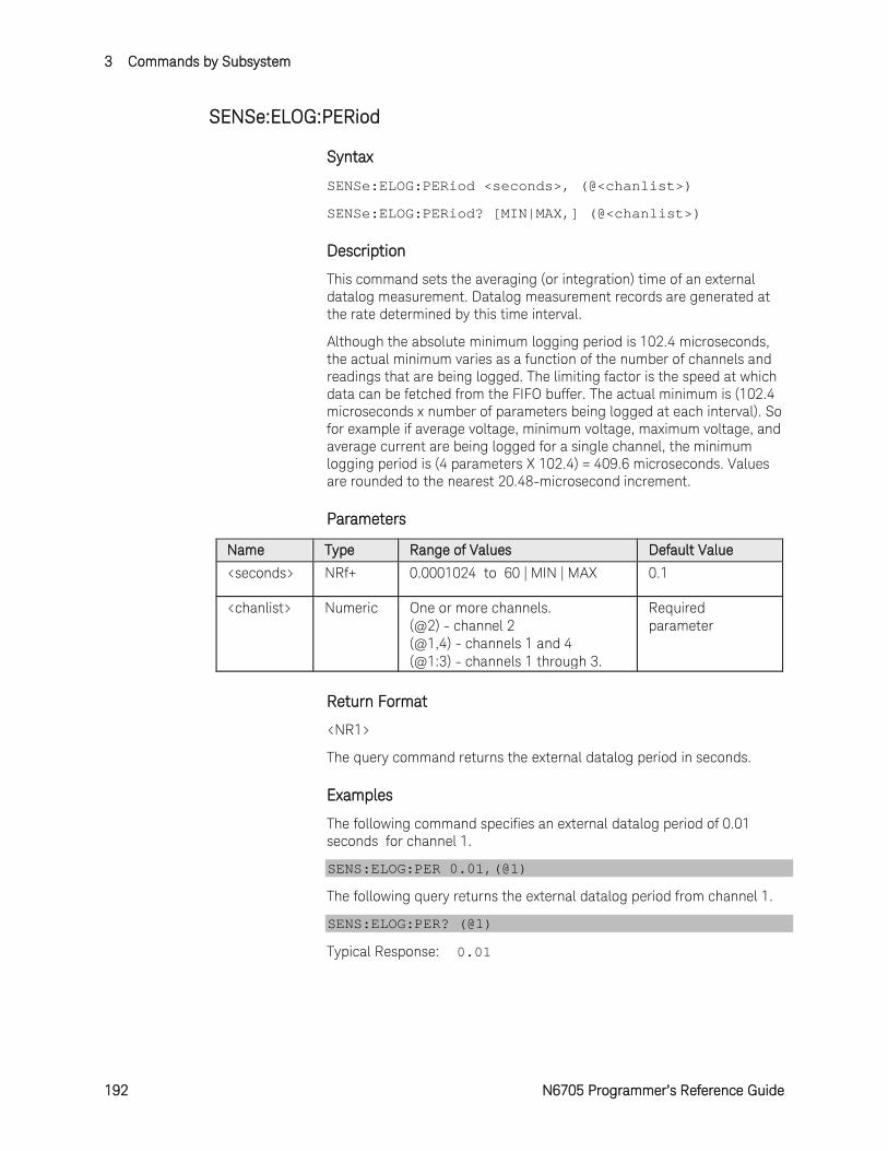
3 Commands by Subsystem
192 N6705 Programmer’s Reference Guide
SENSe:ELOG:PERiod
Syntax
SENSe:ELOG:PERiod <seconds>, (@<chanlist>)
SENSe:ELOG:PERiod? [MIN|MAX,] (@<chanlist>)
Description
This command sets the averaging (or integration) time of an external datalog measurement. Datalog measurement records are generated at the rate determined by this time interval.
Although the absolute minimum logging period is 102.4 microseconds, the actual minimum varies as a function of the number of channels and readings that are being logged. The limiting factor is the speed at which data can be fetched from the FIFO buffer. The actual minimum is (102.4 microseconds x number of parameters being logged at each interval). So for example if average voltage, minimum voltage, maximum voltage, and average current are being logged for a single channel, the minimum logging period is (4 parameters X 102.4) = 409.6 microseconds. Values are rounded to the nearest 20.48-microsecond increment.
Parameters
Name Type Range of Values Default Value <seconds> NRf+ 0.0001024 to 60 | MIN | MAX 0.1
<chanlist> Numeric One or more channels. (@2) - channel 2 (@1,4) - channels 1 and 4 (@1:3) - channels 1 through 3.
Required parameter
Return Format
<NR1>
The query command returns the external datalog period in seconds.
Examples
The following command specifies an external datalog period of 0.01 seconds for channel 1.
SENS:ELOG:PER 0.01,(@1)
The following query returns the external datalog period from channel 1.
SENS:ELOG:PER? (@1)
Typical Response: 0.01
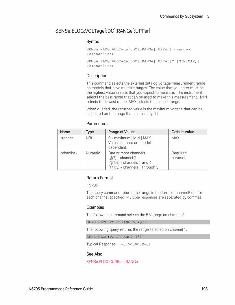
Commands by Subsystem 3
N6705 Programmer’s Reference Guide 193
SENSe:ELOG:VOLTage[:DC]:RANGe[:UPPer]
Syntax
SENSe:ELOG:VOLTage[:DC]:RANGe[:UPPer] <range>, (@<chanlist>)
SENSe:ELOG:VOLTage[:DC]:RANGe[:UPPer]? [MIN|MAX,] (@<chanlist>)
Description
This command selects the external datalog voltage measurement range on models that have multiple ranges. The value that you enter must be the highest value in volts that you expect to measure. The instrument selects the best range that can be used to make this measurement. MIN selects the lowest range; MAX selects the highest range.
When queried, the returned value is the maximum voltage that can be measured on the range that is presently set.
Parameters
Name Type Range of Values Default Value <range> NRf+ 0 - maximum | MIN | MAX
Values entered are model dependent.
MAX
<chanlist> Numeric One or more channels. (@2) - channel 2 (@1,4) - channels 1 and 4 (@1:3) - channels 1 through 3.
Required parameter
Return Format
<NR3>
The query command returns the range in the form +n.nnnnnnE+nn for each channel specified. Multiple responses are separated by commas.
Examples
The following command selects the 5 V range on channel 3.
SENS:ELOG:VOLT:RANG 5,(@3)
The following query returns the range selected on channel 1.
SENS:ELOG:VOLT:RANG? (@1)
Typical Response: +5.500000E+01
See Also
SENSe:ELOG:CURRent:RANGe
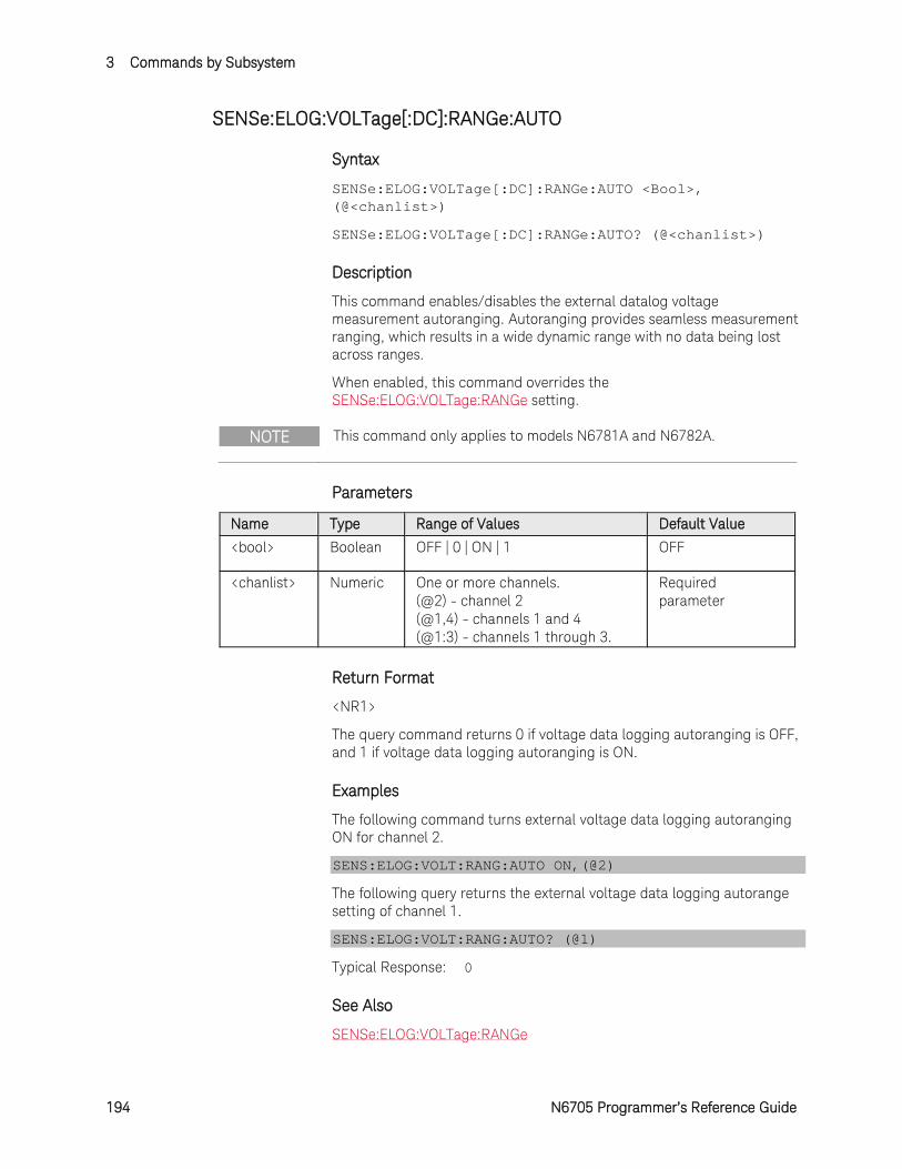
3 Commands by Subsystem
194 N6705 Programmer’s Reference Guide
SENSe:ELOG:VOLTage[:DC]:RANGe:AUTO
Syntax
SENSe:ELOG:VOLTage[:DC]:RANGe:AUTO <Bool>, (@<chanlist>)
SENSe:ELOG:VOLTage[:DC]:RANGe:AUTO? (@<chanlist>)
Description
This command enables/disables the external datalog voltage measurement autoranging. Autoranging provides seamless measurement ranging, which results in a wide dynamic range with no data being lost across ranges.
When enabled, this command overrides the SENSe:ELOG:VOLTage:RANGe setting.
NOTE This command only applies to models N6781A and N6782A.
Parameters
Name Type Range of Values Default Value <bool> Boolean OFF | 0 | ON | 1 OFF
<chanlist> Numeric One or more channels. (@2) - channel 2 (@1,4) - channels 1 and 4 (@1:3) - channels 1 through 3.
Required parameter
Return Format
<NR1>
The query command returns 0 if voltage data logging autoranging is OFF, and 1 if voltage data logging autoranging is ON.
Examples
The following command turns external voltage data logging autoranging ON for channel 2.
SENS:ELOG:VOLT:RANG:AUTO ON,(@2)
The following query returns the external voltage data logging autorange setting of channel 1.
SENS:ELOG:VOLT:RANG:AUTO? (@1)
Typical Response: 0
See Also
SENSe:ELOG:VOLTage:RANGe
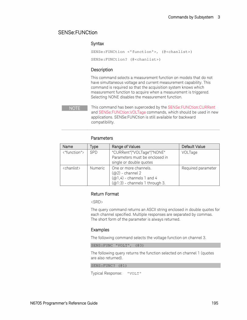
Commands by Subsystem 3
N6705 Programmer’s Reference Guide 195
SENSe:FUNCtion
Syntax
SENSe:FUNCtion <"function">, (@<chanlist>)
SENSe:FUNCtion? (@<chanlist>)
Description
This command selects a measurement function on models that do not have simultaneous voltage and current measurement capability. This command is required so that the acquisition system knows which measurement function to acquire when a measurement is triggered. Selecting NONE disables the measurement function.
NOTE This command has been superceded by the SENSe:FUNCtion:CURRent and SENSe:FUNCtion:VOLTage commands, which should be used in new applications. SENSe:FUNCtion is still available for backward compatibility.
Parameters
Name Type Range of Values Default Value <"function"> SPD "CURRent"|"VOLTage"|"NONE"
Parameters must be enclosed in single or double quotes
VOLTage
<chanlist> Numeric One or more channels. (@2) - channel 2 (@1,4) - channels 1 and 4 (@1:3) - channels 1 through 3.
Required parameter
Return Format
<SRD>
The query command returns an ASCII string enclosed in double quotes for each channel specified. Multiple responses are separated by commas. The short form of the parameter is always returned.
Examples
The following command selects the voltage function on channel 3.
SENS:FUNC "VOLT", (@3)
The following query returns the function selected on channel 1 (quotes are also returned).
SENS:FUNC? (@1)
Typical Response: "VOLT"
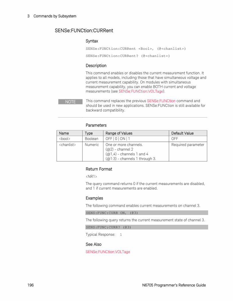
3 Commands by Subsystem
196 N6705 Programmer’s Reference Guide
SENSe:FUNCtion:CURRent
Syntax
SENSe:FUNCtion:CURRent <Bool>, (@<chanlist>)
SENSe:FUNCtion:CURRent? (@<chanlist>)
Description
This command enables or disables the current measurement function. It applies to all models, including those that have simultaneous voltage and current measurement capability. On modules with simultaneous measurement capability, you can enable BOTH current and voltage measurements (see SENSe:FUNCtion:VOLTage).
NOTE This command replaces the previous SENSe:FUNCtion command and should be used in new applications. SENSe:FUNCtion is still available for backward compatibility.
Parameters
Name Type Range of Values Default Value <bool> Boolean OFF | 0 | ON | 1 OFF
<chanlist> Numeric One or more channels. (@2) - channel 2 (@1,4) - channels 1 and 4 (@1:3) - channels 1 through 3.
Required parameter
Return Format
<NR1>
The query command returns 0 if the current measurements are disabled, and 1 if current measurements are enabled.
Examples
The following command enables current measurements on channel 3.
SENS:FUNC:CURR ON, (@3)
The following query returns the current measurement state of channel 3.
SENS:FUNC:CURR? (@3)
Typical Response: 1
See Also
SENSe:FUNCtion:VOLTage
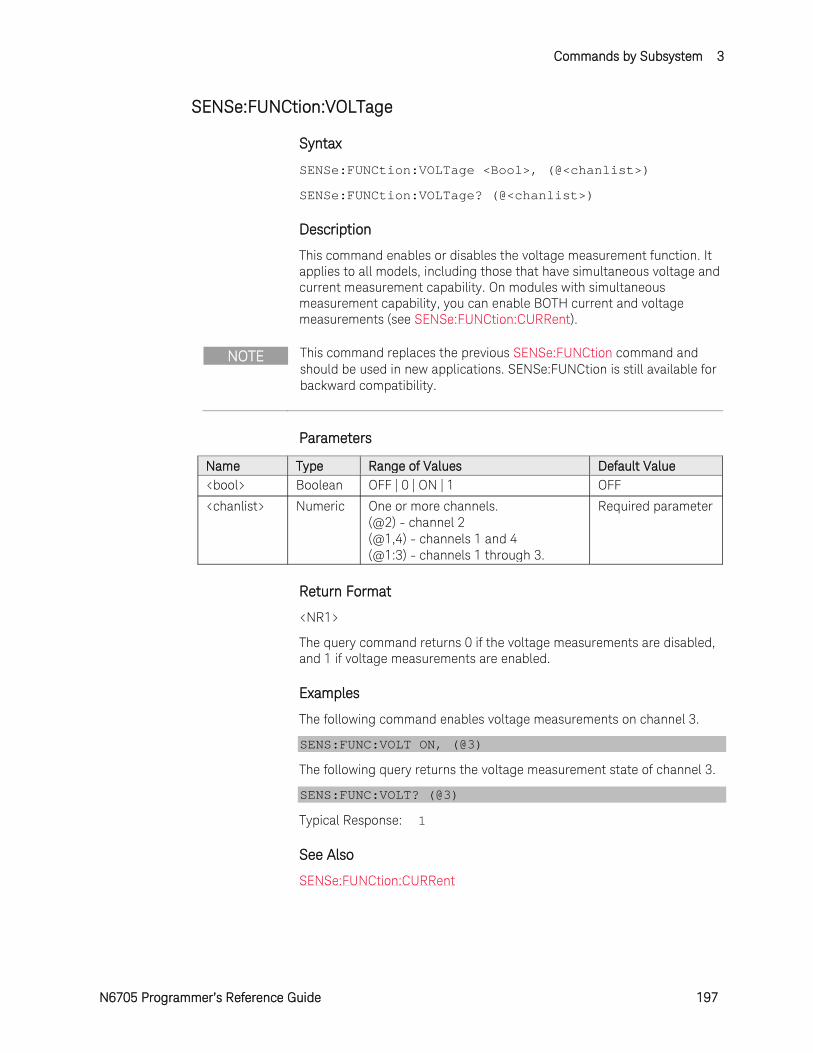
Commands by Subsystem 3
N6705 Programmer’s Reference Guide 197
SENSe:FUNCtion:VOLTage
Syntax
SENSe:FUNCtion:VOLTage <Bool>, (@<chanlist>)
SENSe:FUNCtion:VOLTage? (@<chanlist>)
Description
This command enables or disables the voltage measurement function. It applies to all models, including those that have simultaneous voltage and current measurement capability. On modules with simultaneous measurement capability, you can enable BOTH current and voltage measurements (see SENSe:FUNCtion:CURRent).
NOTE This command replaces the previous SENSe:FUNCtion command and should be used in new applications. SENSe:FUNCtion is still available for backward compatibility.
Parameters
Name Type Range of Values Default Value <bool> Boolean OFF | 0 | ON | 1 OFF
<chanlist> Numeric One or more channels. (@2) - channel 2 (@1,4) - channels 1 and 4 (@1:3) - channels 1 through 3.
Required parameter
Return Format
<NR1>
The query command returns 0 if the voltage measurements are disabled, and 1 if voltage measurements are enabled.
Examples
The following command enables voltage measurements on channel 3.
SENS:FUNC:VOLT ON, (@3)
The following query returns the voltage measurement state of channel 3.
SENS:FUNC:VOLT? (@3)
Typical Response: 1
See Also
SENSe:FUNCtion:CURRent
3 Commands by Subsystem
198 N6705 Programmer’s Reference Guide
SENSe:FUNCtion:VOLTage:INPut
Syntax
SENSe:FUNCtion:VOLTage:INPut <input>, (@<chanlist>)
SENSe:FUNCtion:VOLTage:INPut? (@<chanlist>)
Description
This command selects the voltage measurement input on models that have an auxiliary voltage measurement input. Selecting MAIN selects the front panel binding posts as the measurement inputs. Selecting AUXiliary selects the rear panel auxiliary voltage inputs as the measurement inputs.
NOTE This command only applies to models N6781A and N6785A, which have auxiliary voltage measurement capability.
Parameters
Name Type Range of Values Default Value <input> CPD MAIN | AUXiliary MAIN
<chanlist> Numeric One or more channels. (@2) - channel 2 (@1,4) - channels 1 and 4 (@1:3) - channels 1 through 3.
Required parameter
Return Format
<SRD>
The query command returns an ASCII string for each channel specified. Multiple responses are separated by commas. The short form of the parameter is always returned.
Examples
The following command selects the auxiliary voltage input on channel 3.
SENS:FUNC:VOLT:INP AUX, (@3)
The following query returns the function selected on channel 1.
SENS:FUNC:VOLT:INP? (@1)
Typical Response: MAIN
Commands by Subsystem 3
N6705 Programmer’s Reference Guide 199
SENSe:HISTogram:CURRent[:DC]:BIN:GAIN?
Syntax
SENSe:HISTogram:CURRent[:DC]:BIN:GAIN? <binrange>, (@<chanlist>)
Description
This queries the LSB (or scaling factor) of a histogram in amperes per bin number. Histogram bins are numbered 0 through 4095, and the mean current value of a bin is:
Current = (bin number x gain) + offset
where gain is the value returned by this command, and offset is the value returned by SENS:HIST:CURR:BIN:OFFS. The gains and offsets vary slightly between units of the same model because of software calibration.
Binrange specifies one of the two histogram ranges. Each range has 4096 bins with a minimum and maximum amplitude and a bin size as follows:
Models N6781A/N6782A Models N6785A/N6786A Range; Low High Low High
Amplitude: - 7.8 mA to +7.8 mA
- 8 A to +8 A - 15.6 mA to +15.6 mA
- 16 A to +16 A
Bin Size: 3.8 µA 3.9 mA 7.6 µA 7.8 mA
NOTE This command only applies to models N6781A, N6782A, N6785A and N6786A that have the Data Logger function installed..
Parameters
Name Type Range of Values Default Value <binrange> Numeric 8 | 0.0078 (for N6781A/N6782A)
16 | 0.0156 (for N6785A/N6786A) Required parameter
<chanlist> Numeric One or more channels. (@2) - channel 2 (@1,4) - channels 1 and 4 (@1:3) - channels 1 through 3.
Required parameter
Return Format
<NR3>
The reading is in the form +n.nnnnnnE+nn. Multiple values are separated by commas.
Example
The following query returns the histogram current bin gain of the 8 A range of channel 1.
SENS:HIST:CURR:BIN:GAIN? 8, (@1)

3 Commands by Subsystem
200 N6705 Programmer’s Reference Guide
See Also
SENSe:HISTogram:CURRent:BIN:OFFSet?
Commands by Subsystem 3
N6705 Programmer’s Reference Guide 201
SENSe:HISTogram:CURRent[:DC]:BIN:OFFSet?
Syntax
SENSe:HISTogram:CURRent[:DC]:BIN:OFFSet? <binrange>, (@<chanlist>)
Description
This queries the weight of the histogram in amperes. Histogram bins are numbered 0 through 4095, and the mean current value of a bin is: Current = (bin number x gain) + offset
where gain is the value returned by SENS:HIST:CURR:BIN:GAIN, and offset is the value returned by this command. The gains and offsets vary slightly between units of the same model because of software calibration.
Binrange specifies one of the two histogram ranges. Each range has 4096 bins with a minimum and maximum amplitude and a bin size as follows:
Models N6781A/N6782A Models N6785A/N6786A Range; Low High Low High
Amplitude: - 7.8 mA to +7.8 mA
- 8 A to +8 A - 15.6 mA to +15.6 mA
- 16 A to +16 A
Bin Size: 3.8 µA 3.9 mA 7.6 µA 7.8 mA
NOTE This command only applies to models N6781A, N6782A, N6785A and N6786A that have the Data Logger function installed..
Parameters
Name Type Range of Values Default Value <binrange> Numeric 8 | 0.0078 (for N6781A/N6782A)
16 | 0.0156 (for N6785A/N6786A) Required parameter
<chanlist> Numeric One or more channels. (@2) - channel 2 (@1,4) - channels 1 and 4 (@1:3) - channels 1 through 3.
Required parameter
Return Format
<NR3>
The reading is in the form +n.nnnnnnE+nn. Multiple values are separated by commas.
Example
The following query returns the histogram current bin offset of the 8 A range of channel 1.
SENS:HIST:CURR:BIN:OFFS? 8, (@1)
3 Commands by Subsystem
202 N6705 Programmer’s Reference Guide
See Also
SENSe:HISTogram:CURRent:BIN:GAIN?
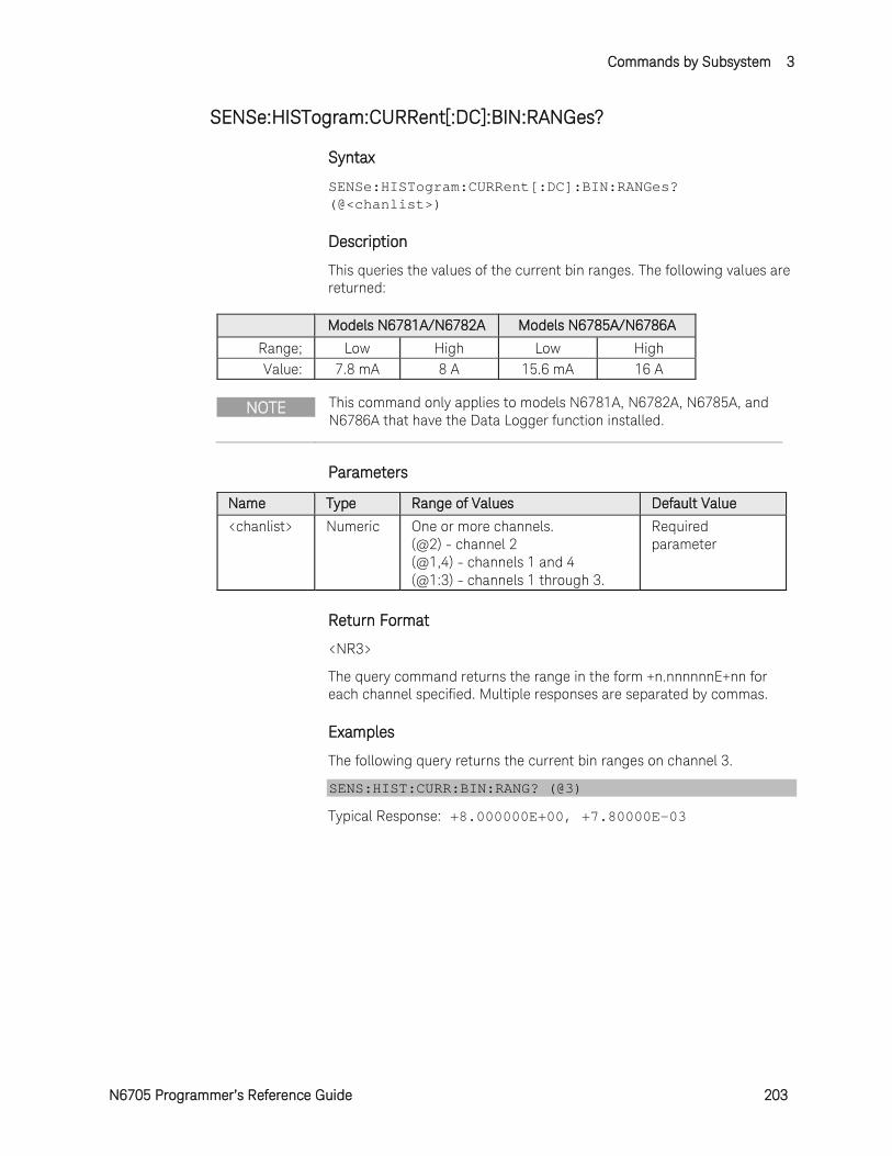
Commands by Subsystem 3
N6705 Programmer’s Reference Guide 203
SENSe:HISTogram:CURRent[:DC]:BIN:RANGes?
Syntax
SENSe:HISTogram:CURRent[:DC]:BIN:RANGes? (@<chanlist>)
Description
This queries the values of the current bin ranges. The following values are returned:
Models N6781A/N6782A Models N6785A/N6786A Range; Low High Low High Value: 7.8 mA 8 A 15.6 mA 16 A
NOTE This command only applies to models N6781A, N6782A, N6785A, and N6786A that have the Data Logger function installed.
Parameters
Name Type Range of Values Default Value <chanlist> Numeric One or more channels.
(@2) - channel 2 (@1,4) - channels 1 and 4 (@1:3) - channels 1 through 3.
Required parameter
Return Format
<NR3>
The query command returns the range in the form +n.nnnnnnE+nn for each channel specified. Multiple responses are separated by commas.
Examples
The following query returns the current bin ranges on channel 3.
SENS:HIST:CURR:BIN:RANG? (@3)
Typical Response: +8.000000E+00, +7.80000E-03
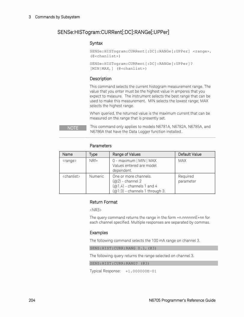
3 Commands by Subsystem
204 N6705 Programmer’s Reference Guide
SENSe:HISTogram:CURRent[:DC]:RANGe[:UPPer]
Syntax
SENSe:HISTogram:CURRent[:DC]:RANGe[:UPPer] <range>, (@<chanlist>)
SENSe:HISTogram:CURRent[:DC]:RANGe[:UPPer]? [MIN|MAX,] (@<chanlist>)
Description
This command selects the current histogram measurement range. The value that you enter must be the highest value in amperes that you expect to measure. The instrument selects the best range that can be used to make this measurement. MIN selects the lowest range; MAX selects the highest range.
When queried, the returned value is the maximum current that can be measured on the range that is presently set.
NOTE This command only applies to models N6781A, N6782A, N6785A, and N6786A that have the Data Logger function installed..
Parameters
Name Type Range of Values Default Value <range> NRf+ 0 - maximum | MIN | MAX
Values entered are model dependent.
MAX
<chanlist> Numeric One or more channels. (@2) - channel 2 (@1,4) - channels 1 and 4 (@1:3) - channels 1 through 3.
Required parameter
Return Format
<NR3>
The query command returns the range in the form +n.nnnnnnE+nn for each channel specified. Multiple responses are separated by commas.
Examples
The following command selects the 100 mA range on channel 3.
SENS:HIST:CURR:RANG 0.1,(@3)
The following query returns the range selected on channel 3.
SENS:HIST:CURR:RANG? (@3)
Typical Response: +1.000000E-01
Commands by Subsystem 3
N6705 Programmer’s Reference Guide 205
See Also
SENSe:HISTogram:CURRent:RANGe:AUTO
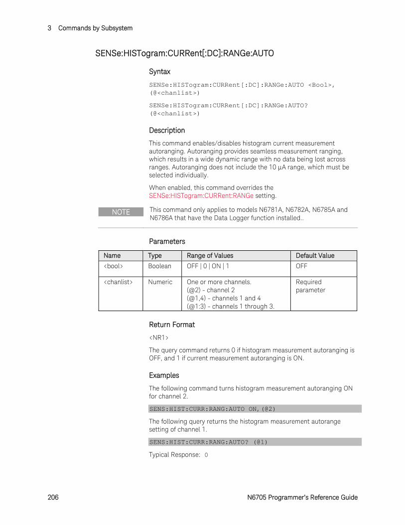
3 Commands by Subsystem
206 N6705 Programmer’s Reference Guide
SENSe:HISTogram:CURRent[:DC]:RANGe:AUTO
Syntax
SENSe:HISTogram:CURRent[:DC]:RANGe:AUTO <Bool>, (@<chanlist>)
SENSe:HISTogram:CURRent[:DC]:RANGe:AUTO? (@<chanlist>)
Description
This command enables/disables histogram current measurement autoranging. Autoranging provides seamless measurement ranging, which results in a wide dynamic range with no data being lost across ranges. Autoranging does not include the 10 μA range, which must be selected individually.
When enabled, this command overrides the SENSe:HISTogram:CURRent:RANGe setting.
NOTE This command only applies to models N6781A, N6782A, N6785A and N6786A that have the Data Logger function installed..
Parameters
Name Type Range of Values Default Value <bool> Boolean OFF | 0 | ON | 1 OFF
<chanlist> Numeric One or more channels. (@2) - channel 2 (@1,4) - channels 1 and 4 (@1:3) - channels 1 through 3.
Required parameter
Return Format
<NR1>
The query command returns 0 if histogram measurement autoranging is OFF, and 1 if current measurement autoranging is ON.
Examples
The following command turns histogram measurement autoranging ON for channel 2.
SENS:HIST:CURR:RANG:AUTO ON,(@2)
The following query returns the histogram measurement autorange setting of channel 1.
SENS:HIST:CURR:RANG:AUTO? (@1)
Typical Response: 0

Commands by Subsystem 3
N6705 Programmer’s Reference Guide 207
See Also
SENSe:HISTogram:CURRent:RANGe
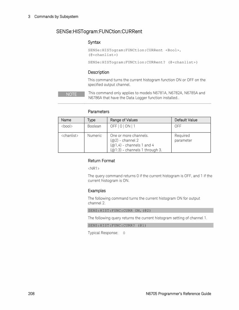
3 Commands by Subsystem
208 N6705 Programmer’s Reference Guide
SENSe:HISTogram:FUNCtion:CURRent
Syntax
SENSe:HISTogram:FUNCtion:CURRent <Bool>, (@<chanlist>)
SENSe:HISTogram:FUNCtion:CURRent? (@<chanlist>)
Description
This command turns the current histogram function ON or OFF on the specified output channel.
NOTE This command only applies to models N6781A, N6782A, N6785A and N6786A that have the Data Logger function installed..
Parameters
Name Type Range of Values Default Value <bool> Boolean OFF | 0 | ON | 1 OFF
<chanlist> Numeric One or more channels. (@2) - channel 2 (@1,4) - channels 1 and 4 (@1:3) - channels 1 through 3.
Required parameter
Return Format
<NR1>
The query command returns 0 if the current histogram is OFF, and 1 if the current histogram is ON.
Examples
The following command turns the current histogram ON for output channel 2.
SENS:HIST:FUNC:CURR ON,(@2)
The following query returns the current histogram setting of channel 1.
SENS:HIST:FUNC:CURR? (@1)
Typical Response: 0
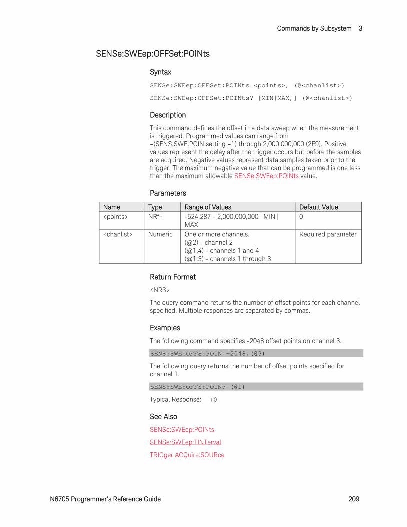
Commands by Subsystem 3
N6705 Programmer’s Reference Guide 209
SENSe:SWEep:OFFSet:POINts
Syntax
SENSe:SWEep:OFFSet:POINts <points>, (@<chanlist>)
SENSe:SWEep:OFFSet:POINts? [MIN|MAX,] (@<chanlist>)
Description
This command defines the offset in a data sweep when the measurement is triggered. Programmed values can range from –(SENS:SWE:POIN setting –1) through 2,000,000,000 (2E9). Positive values represent the delay after the trigger occurs but before the samples are acquired. Negative values represent data samples taken prior to the trigger. The maximum negative value that can be programmed is one less than the maximum allowable SENSe:SWEep:POINts value.
Parameters
Name Type Range of Values Default Value <points> NRf+ -524.287 - 2,000,000,000 | MIN |
MAX 0
<chanlist> Numeric One or more channels. (@2) - channel 2 (@1,4) - channels 1 and 4 (@1:3) - channels 1 through 3.
Required parameter
Return Format
<NR3>
The query command returns the number of offset points for each channel specified. Multiple responses are separated by commas.
Examples
The following command specifies -2048 offset points on channel 3.
SENS:SWE:OFFS:POIN -2048,(@3)
The following query returns the number of offset points specified for channel 1.
SENS:SWE:OFFS:POIN? (@1)
Typical Response: +0
See Also
SENSe:SWEep:POINts
SENSe:SWEep:TINTerval
TRIGger:ACQuire:SOURce
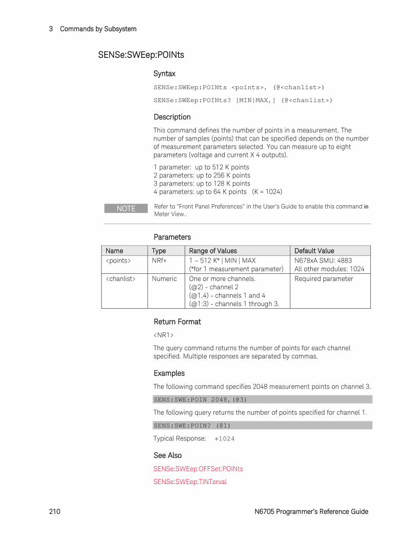
3 Commands by Subsystem
210 N6705 Programmer’s Reference Guide
SENSe:SWEep:POINts
Syntax
SENSe:SWEep:POINts <points>, (@<chanlist>)
SENSe:SWEep:POINts? [MIN|MAX,] (@<chanlist>)
Description
This command defines the number of points in a measurement. The number of samples (points) that can be specified depends on the number of measurement parameters selected. You can measure up to eight parameters (voltage and current X 4 outputs).
1 parameter: up to 512 K points 2 parameters: up to 256 K points 3 parameters: up to 128 K points 4 parameters: up to 64 K points (K = 1024)
NOTE Refer to “Front Panel Preferences” in the User’s Guide to enable this command in Meter View..
Parameters
Name Type Range of Values Default Value <points> NRf+ 1 – 512 K* | MIN | MAX
(*for 1 measurement parameter) N678xA SMU: 4883 All other modules: 1024
<chanlist> Numeric One or more channels. (@2) - channel 2 (@1,4) - channels 1 and 4 (@1:3) - channels 1 through 3.
Required parameter
Return Format
<NR1>
The query command returns the number of points for each channel specified. Multiple responses are separated by commas.
Examples
The following command specifies 2048 measurement points on channel 3.
SENS:SWE:POIN 2048,(@3)
The following query returns the number of points specified for channel 1.
SENS:SWE:POIN? (@1)
Typical Response: +1024
See Also
SENSe:SWEep:OFFSet:POINts
SENSe:SWEep:TINTerval
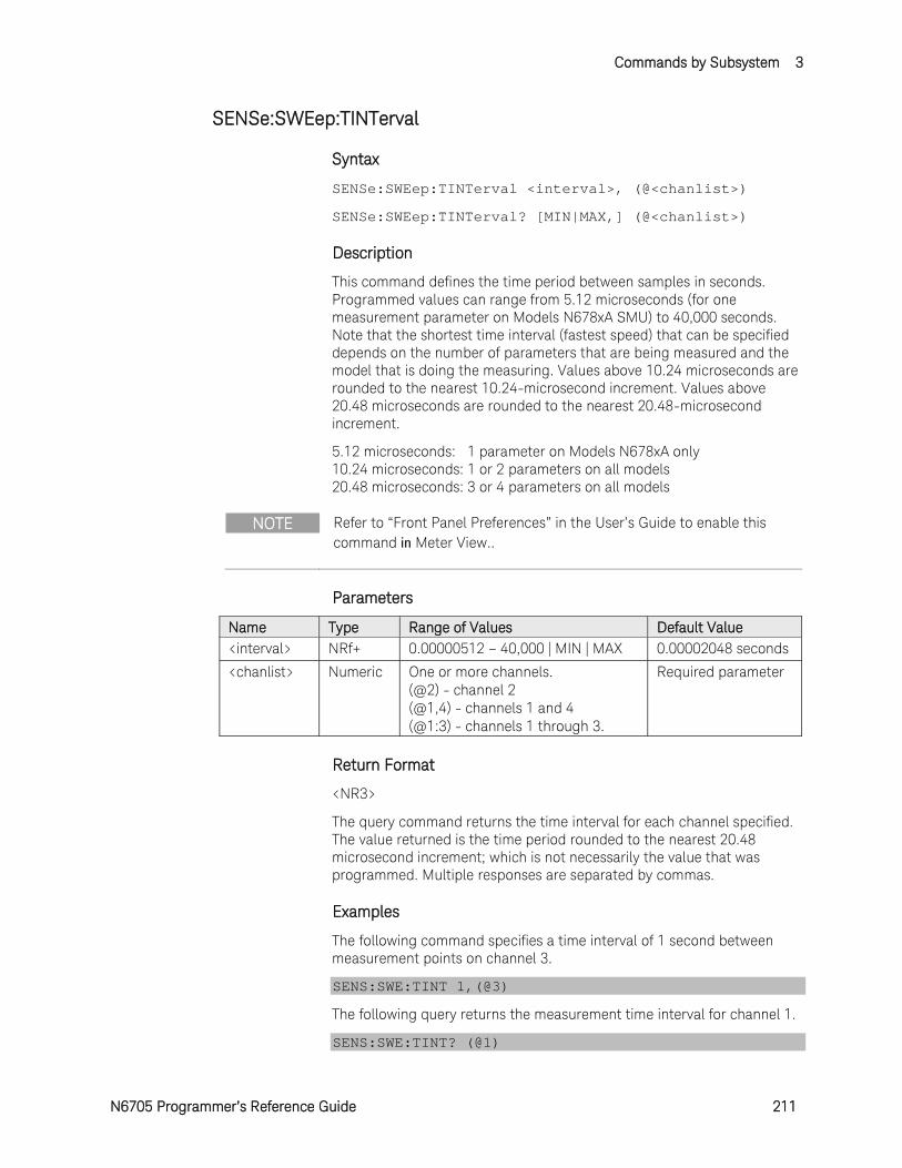
Commands by Subsystem 3
N6705 Programmer’s Reference Guide 211
SENSe:SWEep:TINTerval
Syntax
SENSe:SWEep:TINTerval <interval>, (@<chanlist>)
SENSe:SWEep:TINTerval? [MIN|MAX,] (@<chanlist>)
Description
This command defines the time period between samples in seconds. Programmed values can range from 5.12 microseconds (for one measurement parameter on Models N678xA SMU) to 40,000 seconds. Note that the shortest time interval (fastest speed) that can be specified depends on the number of parameters that are being measured and the model that is doing the measuring. Values above 10.24 microseconds are rounded to the nearest 10.24-microsecond increment. Values above 20.48 microseconds are rounded to the nearest 20.48-microsecond increment.
5.12 microseconds: 1 parameter on Models N678xA only 10.24 microseconds: 1 or 2 parameters on all models 20.48 microseconds: 3 or 4 parameters on all models
NOTE Refer to “Front Panel Preferences” in the User’s Guide to enable this command in Meter View..
Parameters
Name Type Range of Values Default Value <interval> NRf+ 0.00000512 – 40,000 | MIN | MAX 0.00002048 seconds
<chanlist> Numeric One or more channels. (@2) - channel 2 (@1,4) - channels 1 and 4 (@1:3) - channels 1 through 3.
Required parameter
Return Format
<NR3>
The query command returns the time interval for each channel specified. The value returned is the time period rounded to the nearest 20.48 microsecond increment; which is not necessarily the value that was programmed. Multiple responses are separated by commas.
Examples
The following command specifies a time interval of 1 second between measurement points on channel 3.
SENS:SWE:TINT 1,(@3)
The following query returns the measurement time interval for channel 1.
SENS:SWE:TINT? (@1)
3 Commands by Subsystem
212 N6705 Programmer’s Reference Guide
Typical Response: +2.048000E-5
See Also
SENSe:SWEep:OFFSet:POINts
SENSe:SWEep:POINts
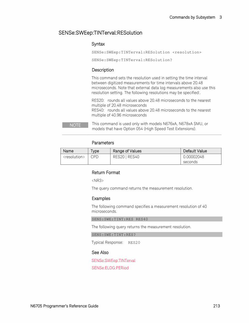
Commands by Subsystem 3
N6705 Programmer’s Reference Guide 213
SENSe:SWEep:TINTerval:RESolution
Syntax
SENSe:SWEep:TINTerval:RESolution <resolution>
SENSe:SWEep:TINTerval:RESolution?
Description
This command sets the resolution used in setting the time interval between digitized measurements for time intervals above 20.48 microseconds. Note that external data log measurements also use this resolution setting. The following resolutions may be specified:.
RES20: rounds all values above 20.48 microseconds to the nearest multiple of 20.48 microseconds RES40: rounds all values above 20.48 microseconds to the nearest multiple of 40.96 microseconds
NOTE This command is used only with models N676xA, N678xA SMU, or models that have Option 054 (High Speed Test Extensions).
Parameters
Name Type Range of Values Default Value <resolution> CPD RES20 | RES40 0.00002048
seconds
Return Format
<NR3>
The query command returns the measurement resolution.
Examples
The following command specifies a measurement resolution of 40 microseconds.
SENS:SWE:TINT:RES RES40
The following query returns the measurement resolution.
SENS:SWE:TINT:RES?
Typical Response: RES20
See Also
SENSe:SWEep:TINTerval
SENSe:ELOG:PERiod
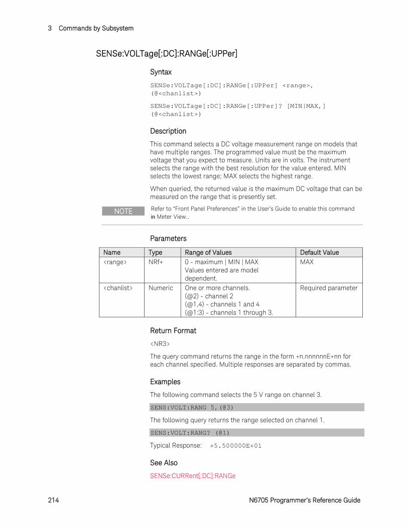
3 Commands by Subsystem
214 N6705 Programmer’s Reference Guide
SENSe:VOLTage[:DC]:RANGe[:UPPer]
Syntax
SENSe:VOLTage[:DC]:RANGe[:UPPer] <range>, (@<chanlist>)
SENSe:VOLTage[:DC]:RANGe[:UPPer]? [MIN|MAX,] (@<chanlist>)
Description
This command selects a DC voltage measurement range on models that have multiple ranges. The programmed value must be the maximum voltage that you expect to measure. Units are in volts. The instrument selects the range with the best resolution for the value entered. MIN selects the lowest range; MAX selects the highest range.
When queried, the returned value is the maximum DC voltage that can be measured on the range that is presently set.
NOTE Refer to “Front Panel Preferences” in the User’s Guide to enable this command in Meter View..
Parameters
Name Type Range of Values Default Value <range> NRf+ 0 - maximum | MIN | MAX
Values entered are model dependent.
MAX
<chanlist> Numeric One or more channels. (@2) - channel 2 (@1,4) - channels 1 and 4 (@1:3) - channels 1 through 3.
Required parameter
Return Format
<NR3>
The query command returns the range in the form +n.nnnnnnE+nn for each channel specified. Multiple responses are separated by commas.
Examples
The following command selects the 5 V range on channel 3.
SENS:VOLT:RANG 5,(@3)
The following query returns the range selected on channel 1.
SENS:VOLT:RANG? (@1)
Typical Response: +5.500000E+01
See Also
SENSe:CURRent[:DC]:RANGe
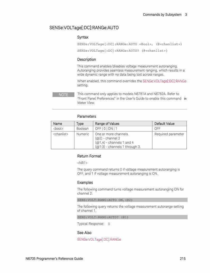
Commands by Subsystem 3
N6705 Programmer’s Reference Guide 215
SENSe:VOLTage[:DC]:RANGe:AUTO
Syntax
SENSe:VOLTage[:DC]:RANGe:AUTO <Bool>, (@<chanlist>)
SENSe:VOLTage[:DC]:RANGe:AUTO? (@<chanlist>)
Description
This command enables/disables voltage measurement autoranging. Autoranging provides seamless measurement ranging, which results in a wide dynamic range with no data being lost across ranges.
When enabled, this command overrides the SENSe:VOLTage[:DC]:RANGe setting.
NOTE This command only applies to models N6781A and N6782A. Refer to “Front Panel Preferences” in the User’s Guide to enable this command in Meter View.
Parameters
Name Type Range of Values Default Value <bool> Boolean OFF | 0 | ON | 1 OFF
<chanlist> Numeric One or more channels. (@2) - channel 2 (@1,4) - channels 1 and 4 (@1:3) - channels 1 through 3.
Required parameter
Return Format
<NR1>
The query command returns 0 if voltage measurement autoranging is OFF, and 1 if voltage measurement autoranging is ON.
Examples
The following command turns voltage measurement autoranging ON for channel 2.
SENS:VOLT:RANG:AUTO ON,(@2)
The following query returns the voltage measurement autorange setting of channel 1.
SENS:VOLT:RANG:AUTO? (@1)
Typical Response: 0
See Also
SENSe:VOLTage[:DC]:RANGe
3 Commands by Subsystem
216 N6705 Programmer’s Reference Guide
SENSe:WINDow[:TYPE]
Syntax
SENSe:WINDow[:TYPE] <window>, (@<chanlist>)
SENSe:WINDow[:TYPE]? (@<chanlist>)
Description
This command sets a signal conditioning function used in DC measurement calculations on models that have measurement controls. Select from the following filter window types:
HANNing The Hanning window is a "raised cosine" function. It is a signal conditioning function that reduces errors in DC measurement calculations in the presence of periodic signals such as AC line ripple.
RECTangular A window that returns measurement calculations with no signal conditioning.
Note that neither window function alters the instantaneous voltage or current data returned in the measurement array.
NOTE Refer to “Front Panel Preferences” in the User’s Guide to enable this command in Meter View..
Parameters
Name Type Range of Values Default Value <window> CPD HANNing | RECTangular RECTangular
<chanlist> Numeric One or more channels. (@2) - channel 2 (@1,4) - channels 1 and 4 (@1:3) - channels 1 through 3.
Required parameter
Return Format
<CRD>
The query command returns the window setting for each channel specified. Multiple responses are separated by commas.
Examples
The following command specifies a RECTangular measurement window for channel 3.
SENS:WIND RECT,(@3)
The following query returns the measurement window for channel 1.
SENS:WIND? (@1)
Typical Response: RECT
Commands by Subsystem 3
N6705 Programmer’s Reference Guide 217
SOURce Subsystem Introduction
The Source subsystem programs the current, digital, list, step, and voltage functions.
SCPI Command Description [SOURce:]ARB :COUNt <NRf+> | INFinity, (@chanlist) Sets the Arb repeat count :CURRent | :VOLTage Specifies current or voltage Arbs :CDWell [:LEVel] < NRf+> ,<NRf>, (@chanlist) Sets the list of the constant dwell Arb :DWELl < NRf+>, (@chanlist) Sets the dwell time for the constant dwell Arb :POINts? (@<chanlist>) Returns the number of constant-dwell Arb points :CONVert (@chanlist) Converts the selected Arb to a user-defined list :EXPonential :END [:LEVel] < NRf+>, (@chanlist) Sets the end level of the exponential Arb :STARt [:LEVel] < NRf+>, (@chanlist) Sets the initial level of the exponential Arb :TIMe < NRf+>, (@chanlist) Sets the length of the start time or delay :TCONstant < NRf+>, (@chanlist) Sets the time constant of the exponential Arb :TIMe < NRf+>, (@chanlist) Sets the time of the exponential Arb :PULSe :END :TIMe < NRf+>, (@chanlist) Sets the length of the end time :STARt [:LEVel] < NRf+>, (@chanlist) Sets the initial level of the pulse :TIMe < NRf+>, (@chanlist) Sets the length of the start time or delay :TOP [:LEVel] < NRf+>, (@chanlist) Sets the top level of the pulse :TIMe < NRf+>, (@chanlist) Sets the length of the pulse :RAMP :END [:LEVel] < NRf+>, (@chanlist) Sets the end level of the ramp :TIMe < NRf+>, (@chanlist) Sets the length of the end time :RTIMe < NRf+>, (@chanlist) Sets the rise time of the ramp :STARt [:LEVel] < NRf+>, (@chanlist) Sets the initial level of the ramp :TIMe < NRf+>, (@chanlist) Sets the length of the start time or delay :SINusoid :AMPLitude < NRf+>, (@chanlist) Sets the amplitude of the sine wave :FREQuency < NRf+>, (@chanlist) Sets the frequency of the sine wave :OFFSet < NRf+>, (@chanlist) Sets the DC offset of the sine wave :STAircase :END [:LEVel] < NRf+>, (@chanlist) Sets the end level of the staircase :TIMe < NRf+>, (@chanlist) Sets the length of the end time :NSTeps < NRf+>, (@chanlist) Sets the number of steps in the staircase :STARt [:LEVel] < NRf+>, (@chanlist) Sets the initial level of the staircase :TIMe < NRf+>, (@chanlist) Sets the length of the start time or delay :TIMe <NRf+>, (@chanlist) Sets the length of the staircase :STEP :END [:LEVel] < NRf+>, (@chanlist) Sets the end level of the step :STARt [:LEVel] < NRf+>, (@chanlistl) Sets the initial level of the step :TIMe < NRf+>, (@chanlist) Sets the length of the start time or delay
3 Commands by Subsystem
218 N6705 Programmer’s Reference Guide
SCPI Command Description [SOURce:]ARB (continued) :TRAPezoid :END :TIMe < NRf+>, (@chanlist) Sets the length of the end time :FTIMe < NRf+>, (@chanlist) Sets the length of the fall time :RTIMe < NRf+>, (@chanlist) Sets the length of the rise time :STARt [:LEVel] < NRf+>, (@chanlist) Sets the initial level of the trapezoid :TIMe < NRf+>, (@chanlist) Sets the length of the start time or delay :TOP [:LEVel] < NRf+>, (@chanlist) Sets the top level of the trapezoid :TIMe < NRf+>, (@chanlist) Sets the length of the top of the trapezoid :UDEFined :BOSTep [:DATA] <Bool> ,<Bool>, (@chanlist) Generate triggers at the Beginning Of STep :POINts? (@chanlist) Returns the number of BOST points :DWELl <NRf> ,<NRf>, (@chanlist) Sets the user-defined dwell values :POINts? (@chanlist) Returns the number of dwell points :LEVel <NRf> ,<NRf>, (@chanlist) Sets the user-defined level values :POINts? (@chanlist) Returns the number of points :FUNCtion <function>, (@chanlist) Selects the Arb function (for backward compatibility) :SHAPe <function>, (@chanlist) Selects the Arb function (replaces ARB:FUNCtion) :TYPE CURRent | VOLTage, (@chanlist) Selects the Arb type (replaces ARB:FUNCtion) :SEQuence :COUNt <NRf+> | INFinity, (@chanlist) Sets the number of times the sequence is repeated :LENgth? (@chanlist) Returns the number of steps in the sequence :QUALity? (@chanlist) Returns the quality of the waveforms in the sequence :RESet (@chanlist) Resets the sequence to its power-on default setting :STEP :COUNt <NRf+> | INFinity, <step#>, (@chanlist) Sets the number of times the sequence step is repeated :CURRent <ARB_function>, <step#>, (@chanlist) Programs the waveform steps within a current sequence :FUNCtion :SHAPe <function>, <step#>, (@chanlist) Creates a new sequence step :PACing DWELl | TRIGger, <step#>, (@chanlist) Specifies the type of pacing for the step :VOLTage <ARB_function>, <step#>, (@chanlist) Programs the waveform steps within a voltage sequence :TERMinate :LAST <Bool>, (@chanlist) Sets the sequence termination mode :TERMinate :LAST <Bool>, (@chanlist) Sets the Arb termination mode [SOURce:]CURRent [:LEVel] [:IMMediate][:AMPLitude] <NRf+>, (@chanlist) Sets the output current :TRIGgered [:AMPLitude] <NRf+>, (@chanlist) Sets the triggered output current :LIMit [:POSitive] [:IMMediate][:AMPLitude] <NRf+>, (@chanlist) Sets the positive current limit (only on N678xA SMU, N6783A) :COUPle <Bool>, (@chanlist) Sets the current limit tracking state (only on N678xA SMU) :NEGative [:IMMediate][:AMPLitude] <NRf+>, (@chanlist) Sets the negative current limit (only on N678xA SMU, N6783A-BAT) :MODE FIXed | STEP | LIST | ARB, (@chanlist) Sets the current trigger mode :PROTection :DELay [:TIME] <NRf+> (@chanlist) Sets the over-current protection programming delay :STARt SCHange | CCTRans, (@chanlist) Sets the over-current protection programming mode :STATe <Bool>, (@chanlist) Enables/disables over-current protection on the selected output :RANGe <NRf+>, (@chanlist) Sets the output current range :SLEW [:IMMediate] <NRf+> | INFinity, (@chanlist) Sets the output current slew rate (N678xA SMU) MAXimum <Bool>, (@chanlist) Enables/disables the maximum slew rate override (N678xA SMU)
Commands by Subsystem 3
N6705 Programmer’s Reference Guide 219
SCPI Command Description [SOURce:]DIGital :INPut :DATA? Reads the state of the digital port pins :OUTPut :DATA <NRf> Sets the digital port :PIN<1-7> :FUNCtion <function> Sets the selected pin’s function <function>= DIO, DINPut, TOUTput, TINPput, FAULt, INHibit, ONCouple, OFFCouple :POLarity POSitive | NEGative Sets the selected pin’s polarity :TOUTput :BUS [:ENABle] <Bool> Enables/disables BUS-generated triggers on digital pins [SOURce:]EMULation <type>, (@chanlist) Specifies the emulation mode on N678xA <type> = PS4Q, PS2Q, PS1Q, BATTery, CHARger, CCLoad, CVLoad, VMETer, AMETer [SOURce:]FUNCtion CURRent | VOLTage, (@chanlist) Specifies current priority or voltage priority mode (N678xA SMU) [SOURce:]LIST :COUNt <NRf+> | INFinity, (@chanlist) Sets the list repeat count :CURRent [:LEVel] <NRf> ,<NRf>, (@chanlist) Sets the current list :POINts? (@chanlist) Returns the number of current list points :DWELl <NRf> ,<NRf>, (@chanlist) Sets the list of dwell times :POINts? (@chanlist) Returns the number of dwell list points :STEP ONCE | AUTO, (@chanlist) Specifies how the list responds to triggers :TERMinate :LAST <Bool>, (@chanlist) Sets the list termination mode :TOUTput :BOSTep [:DATA] <Bool> ,<Bool>, (@chanlist) Generate triggers at the Beginning Of STep :POINts? (@chanlist) Returns the number of BOST list points :EOSTep [:DATA] <Bool> ,<Bool>, (@chanlist) Generate triggers at the End Of STep :POINts? (@chanlist) Returns the number of EOST list points :VOLTage [:LEVel] <NRf> ,<NRf>, (@chanlist) Sets the voltage list :POINts? (@chanlist) Returns the number of voltage list points [SOURce:]POWer :LIMit <NRf+>, (@chanlist) Sets the power limit on output channels [SOURce:]RESistance [:LEVel] [:IMMediate][:AMPLitude] <NRf+>, (@chanlist) Sets the output resistance (only on N6781A, N6785A) :STATe <Bool>, (@chanlist) Enables/disables output resistance programming (N6781A, N6785A) [SOURce:]STEP :TOUTput <Bool>, (@chanlist) Generate a trigger output on the voltage or current step [SOURce:]VOLTage [:LEVel] [:IMMediate][:AMPLitude] <NRf+>, (@chanlist) Sets the output voltage :TRIGgered [:AMPLitude] <NRf+>, (@chanlist) Sets the triggered output voltage :BWIDth DEFault | FAST1 | FAST2 | FAST3, (@chanlist) Sets the voltage bandwidth (only on N678xA SMU) :LIMit [:POSitive] [:IMMediate][:AMPLitude] <NRf+>, (@chanlist) Sets the positive voltage limit (only on N678xA SMU) :COUPle <Bool>, (@chanlist) Sets the voltage limit tracking state (only on N6784A) :NEGative [:IMMediate][:AMPLitude] <NRf+>, (@chanlist) Sets the negative voltage limit (only on N6784A) :MODE FIXed | STEP | LIST | ARB, (@chanlist) Sets the voltage trigger mode
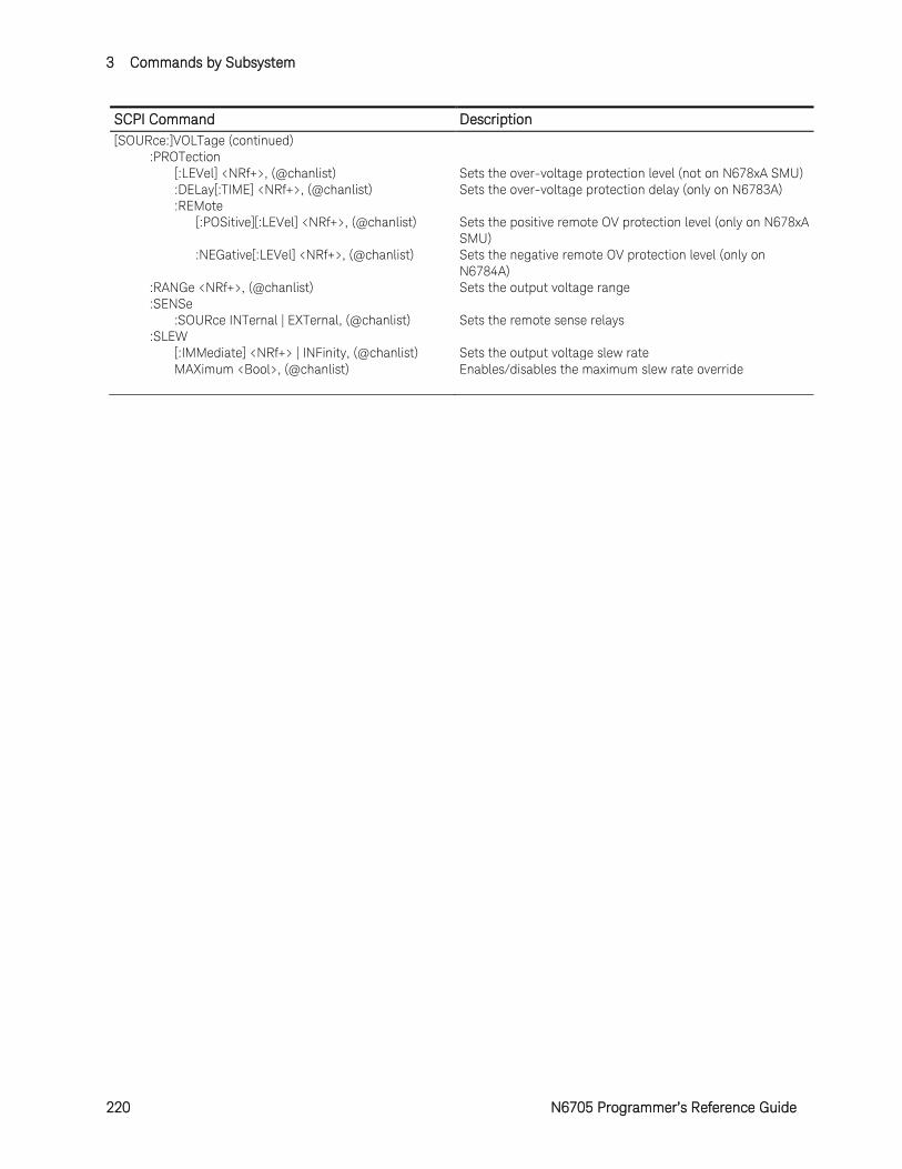
3 Commands by Subsystem
220 N6705 Programmer’s Reference Guide
SCPI Command Description [SOURce:]VOLTage (continued) :PROTection [:LEVel] <NRf+>, (@chanlist) Sets the over-voltage protection level (not on N678xA SMU) :DELay[:TIME] <NRf+>, (@chanlist) Sets the over-voltage protection delay (only on N6783A) :REMote [:POSitive][:LEVel] <NRf+>, (@chanlist) Sets the positive remote OV protection level (only on N678xA
SMU) :NEGative[:LEVel] <NRf+>, (@chanlist) Sets the negative remote OV protection level (only on
N6784A) :RANGe <NRf+>, (@chanlist) Sets the output voltage range :SENSe :SOURce INTernal | EXTernal, (@chanlist) Sets the remote sense relays :SLEW [:IMMediate] <NRf+> | INFinity, (@chanlist) Sets the output voltage slew rate MAXimum <Bool>, (@chanlist) Enables/disables the maximum slew rate override
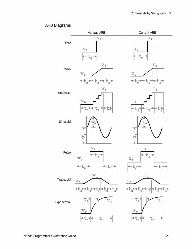
Commands by Subsystem 3
N6705 Programmer’s Reference Guide 221
ARB Diagrams
Voltage ARB Current ARB
Step
Ramp
Staircase
Sinusoid
Pulse
Trapezoid
Exponential
3 Commands by Subsystem
222 N6705 Programmer’s Reference Guide
[SOURce:]ARB:COUNt
Syntax
[SOURce:]ARB:COUNt <count>|INFinity, (@<chanlist>)
[SOURce:]ARB:COUNt? [MIN|MAX|INFinity,] (@<chanlist>)
Description
This command sets the number of times that the arbitrary waveform is repeated. The repeat count range is 1 through >16 million. For constant-dwell Arbs only, the maximum count is limited to 256.
Parameters
Name Type Range of Values Default Value
<count> NRf+ 1 - 16,777,216 | MIN | MAX | INFinity
1
<chanlist> Numeric One or more channels. (@2) - channel 2 (@1,4) - channels 1 and 4 (@1:3) - channels 1 through 3.
Required parameter
Remarks
Use the INFinity parameter to repeat the arbitrary waveform continuously. If MAX, or a value greater than 16,777,216 is programmed, the Arb will also repeat continuously.
Use ABORt:TRANsient to stop the Arb at any time. When the Arb is aborted, the output returns to the settings that were in effect before the Arb started.
Return Format
<NR3>
The query command returns the repeat count for each channel specified. Multiple responses are separated by commas. If a repeat count of 9.9E37 is returned, it means that the Arb is set to repeat continuously.
Examples
The following command sets the repeat count to 10 on channel 1.
ARB:COUN 10,(@1)
The following query returns the repeat count of channel 1.
ARB:COUN? (@1)
Typical Response: +10
Commands by Subsystem 3
N6705 Programmer’s Reference Guide 223
[SOURce:]ARB:CURRent:CDWell[:LEVel]
Syntax
[SOURce:]ARB:CURRent:CDWell[:LEVel] <current>,<current>, (@<chanlist>)
[SOURce:]ARB:CURRent:CDWell[:LEVel]? (@<chanlist>)
Description
This command specifies the level of each point of a constant-dwell ARB. Current and voltage CD ARBs share settings, so setting the current CD ARB resets the voltage CD ARB level to its default value and vice-versa. A comma-delimited list of up to 65,535 points may be programmed.
For better performance, the list of current points can be sent as a definite length binary block instead of an ASCII list.
Parameters
Name Type Range of Values Default Value
<current> NRf or <block>
0 – maximum The maximum value is dependent on the current rating of the power module.
1 point set to the minimum programmable value
<chanlist> Numeric One or more channels. (@2) - channel 2 (@1,4) - channels 1 and 4 (@1:3) - channels 1 through 3.
Required parameter
Return Format
The return format depends on the settings of the FORMat:BORDer and FORMat[:DATA] commands. When the data format is set to ASCII, returned values are comma separated. Only one channel can be queried when the format is ASCII. When the data format is set to REAL, data is returned as single precision floating point numbers in definite length arbitrary block response format. Each block contains all the records for one of the channels given in the <chanlist> parameter. If multiple channels are given, then each definite length arbitrary block of data is separated by a comma.
<NR3> [,<NR3>] or <block> [,<block>]
Examples
The following command programs a constant-dwell current ARB. The ARB contains 5 points and is on channel 1.
ARB:CURR:CDW 5,4,3,2,1,(@1)
The following query returns the constant-dwell current settings of
3 Commands by Subsystem
224 N6705 Programmer’s Reference Guide
channel 1.
ARB:CURR:CDW? (@1)
See Also
[SOURce:]ARB:CURRent:CDWell:DWELl
FORMat:BORDer
FORMat[:DATA]
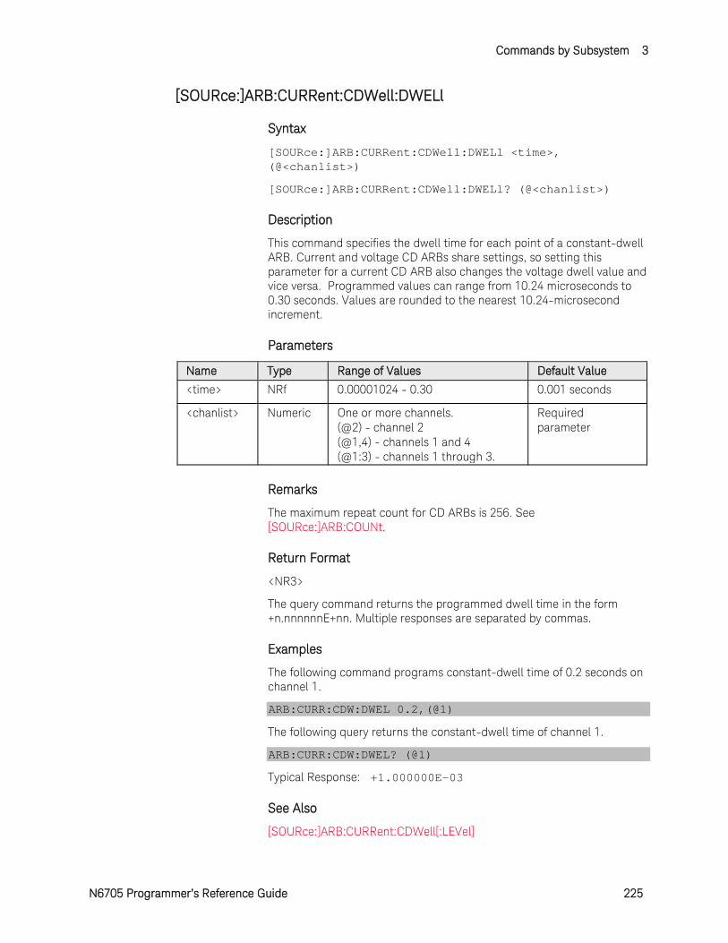
Commands by Subsystem 3
N6705 Programmer’s Reference Guide 225
[SOURce:]ARB:CURRent:CDWell:DWELl
Syntax
[SOURce:]ARB:CURRent:CDWell:DWELl <time>, (@<chanlist>)
[SOURce:]ARB:CURRent:CDWell:DWELl? (@<chanlist>)
Description
This command specifies the dwell time for each point of a constant-dwell ARB. Current and voltage CD ARBs share settings, so setting this parameter for a current CD ARB also changes the voltage dwell value and vice versa. Programmed values can range from 10.24 microseconds to 0.30 seconds. Values are rounded to the nearest 10.24-microsecond increment.
Parameters
Name Type Range of Values Default Value
<time> NRf 0.00001024 - 0.30 0.001 seconds
<chanlist> Numeric One or more channels. (@2) - channel 2 (@1,4) - channels 1 and 4 (@1:3) - channels 1 through 3.
Required parameter
Remarks
The maximum repeat count for CD ARBs is 256. See [SOURce:]ARB:COUNt.
Return Format
<NR3>
The query command returns the programmed dwell time in the form +n.nnnnnnE+nn. Multiple responses are separated by commas.
Examples
The following command programs constant-dwell time of 0.2 seconds on channel 1.
ARB:CURR:CDW:DWEL 0.2,(@1)
The following query returns the constant-dwell time of channel 1.
ARB:CURR:CDW:DWEL? (@1)
Typical Response: +1.000000E-03
See Also
[SOURce:]ARB:CURRent:CDWell[:LEVel]
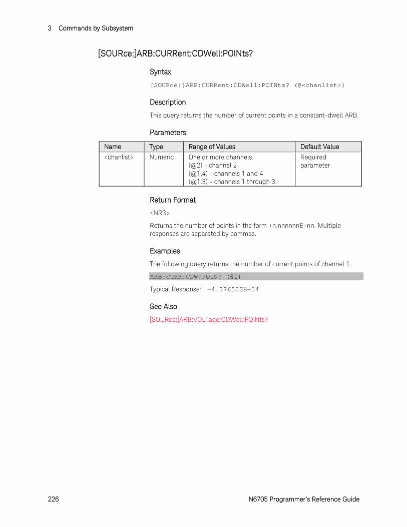
3 Commands by Subsystem
226 N6705 Programmer’s Reference Guide
[SOURce:]ARB:CURRent:CDWell:POINts?
Syntax
[SOURce:]ARB:CURRent:CDWell:POINts? (@<chanlist>)
Description
This query returns the number of current points in a constant-dwell ARB.
Parameters
Name Type Range of Values Default Value
<chanlist> Numeric One or more channels. (@2) - channel 2 (@1,4) - channels 1 and 4 (@1:3) - channels 1 through 3.
Required parameter
Return Format
<NR3>
Returns the number of points in the form +n.nnnnnnE+nn. Multiple responses are separated by commas.
Examples
The following query returns the number of current points of channel 1.
ARB:CURR:CDW:POIN? (@1)
Typical Response: +4.376500E+04
See Also
[SOURce:]ARB:VOLTage:CDWell:POINts?
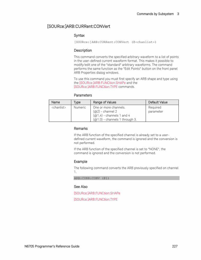
Commands by Subsystem 3
N6705 Programmer’s Reference Guide 227
[SOURce:]ARB:CURRent:CONVert
Syntax
[SOURce:]ARB:CURRent:CONVert (@<chanlist>)
Description
This command converts the specified arbitrary waveform to a list of points in the user-defined current waveform format. This makes it possible to modify/edit one of the "standard" arbitrary waveforms. The command performs the same function as the "Edit Points" button on the front panel ARB Properties dialog windows.
To use this command you must first specify an ARB shape and type using the [SOURce:]ARB:FUNCtion:SHAPe and the [SOURce:]ARB:FUNCtion:TYPE commands.
Parameters
Name Type Range of Values Default Value
<chanlist> Numeric One or more channels. (@2) - channel 2 (@1,4) - channels 1 and 4 (@1:3) - channels 1 through 3.
Required parameter
Remarks
If the ARB function of the specified channel is already set to a user-defined current waveform, the command is ignored and the conversion is not performed.
If the ARB function of the specified channel is set to "NONE", the command is ignored and the conversion is not performed.
Example
The following command converts the ARB previously specified on channel 1.
ARB:CURR:CONV (@1)
See Also
[SOURce:]ARB:FUNCtion:SHAPe
[SOURce:]ARB:FUNCtion:TYPE
3 Commands by Subsystem
228 N6705 Programmer’s Reference Guide
[SOURce:]ARB:CURRent:EXPonential:END[:LEVel] [SOURce:]ARB:SEQuence:STEP:CURRent:EXPonential:END[:LEVel]
Syntax
[SOURce:]ARB:CURRent:EXPonential:END[:LEVel] <current>, (@<chanlist>)
[SOURce:]ARB:CURRent:EXPonential:END[:LEVel]? [MIN|MAX,] (@<chanlist>)
For ARB sequence steps:
[SOURce:]ARB:SEQuence:STEP:CURRent:EXPonential:END [:LEVel] <current>, <step#>, (@<chanlist>)
[SOURce:]ARB:SEQuence:STEP:CURRent:EXPonential:END [:LEVel]? [MIN|MAX,] <step#>, (@<chanlist>)
Description
This command specifies the end level current (after the exponential waveform ends) in amperes. Referenced to I1 in the Exponential diagram.
Parameters
Name Type Range of Values Default Value
<current> NRf+ 0 – maximum | MIN | MAX The maximum value is dependent on the current rating of the power module.
MIN
<step#> NR1 1 - 100 1
<chanlist> Numeric One or more channels. (@2) - channel 2 (@1,4) - channels 1 and 4 (@1:3) - channels 1 through 3.
Required parameter
Return Format
<NR3>
The query command returns the programmed current level in the form +n.nnnnnnE+nn. Multiple responses are separated by commas.
Examples
The following command programs an end level current for the exponential waveform on channel 1.
ARB:CURR:EXP:END 1,(@1) ARB:SEQ:STEP:CURR:EXP:END 1, 1,(@1)
The following query returns the end level current of channel 1.
Commands by Subsystem 3
N6705 Programmer’s Reference Guide 229
ARB:CURR:EXP:END? (@1) ARB:SEQ:STEP:CURR:EXP:END? 1,(@1)
Typical Response: +1.000000E+00
See Also
[SOURce:]ARB:CURRent:EXPonential:STARt[:LEVel]
3 Commands by Subsystem
230 N6705 Programmer’s Reference Guide
[SOURce:]ARB:CURRent:EXPonential:STARt[:LEVel] [SOURce:]ARB:SEQuence:STEP:CURRent:EXPonential:STARt[:LEVel]
Syntax
[SOURce:]ARB:CURRent:EXPonential:STARt[:LEVel] <current>, (@<chanlist>)
[SOURce:]ARB:CURRent:EXPonential:STARt[:LEVel]? [MIN|MAX,] (@<chanlist>)
For ARB sequence steps:
[SOURce:]ARB:SEQuence:STEP:CURRent:EXPonential:STARt[:LEVel] <current>, <step#>, (@<chanlist>)
[SOURce:]ARB:SEQuence:STEP:CURRent:EXPonential:STARt[:LEVel]? [MIN|MAX,] <step#>, (@<chanlist>)
Description
This command specifies the initial current (before the exponential waveform starts) in amperes. Referenced to I0 in the Exponential diagram.
Parameters
Name Type Range of Values Default Value
<current> NRf+ 0 – maximum | MIN | MAX The maximum value is dependent on the current rating of the power module.
MIN
<step#> NR1 1 - 100 1
<chanlist> Numeric One or more channels. (@2) - channel 2 (@1,4) - channels 1 and 4 (@1:3) - channels 1 through 3.
Required parameter
Return Format
<NR3>
The query command returns the programmed current level in the form +n.nnnnnnE+nn1. Multiple responses are separated by commas.
Examples
The following command programs an start level current for the exponential waveform on channel 1.
ARB:CURR:EXP:STAR 1,(@1) ARB:SEQ:STEP:CURR:EXP:STAR 1, 1,(@1)
The following query returns the start level current of channel 1.
Commands by Subsystem 3
N6705 Programmer’s Reference Guide 231
ARB:CURR:EXP:STAR? (@1) ARB:SEQ:STEP:CURR:EXP:STAR? 1,(@1)
Typical Response: +1.000000E+00
See Also
[SOURce:]ARB:CURRent:EXPonential:STARt:TIMe
[SOURce:]ARB:CURRent:EXPonential:END[:LEVel]
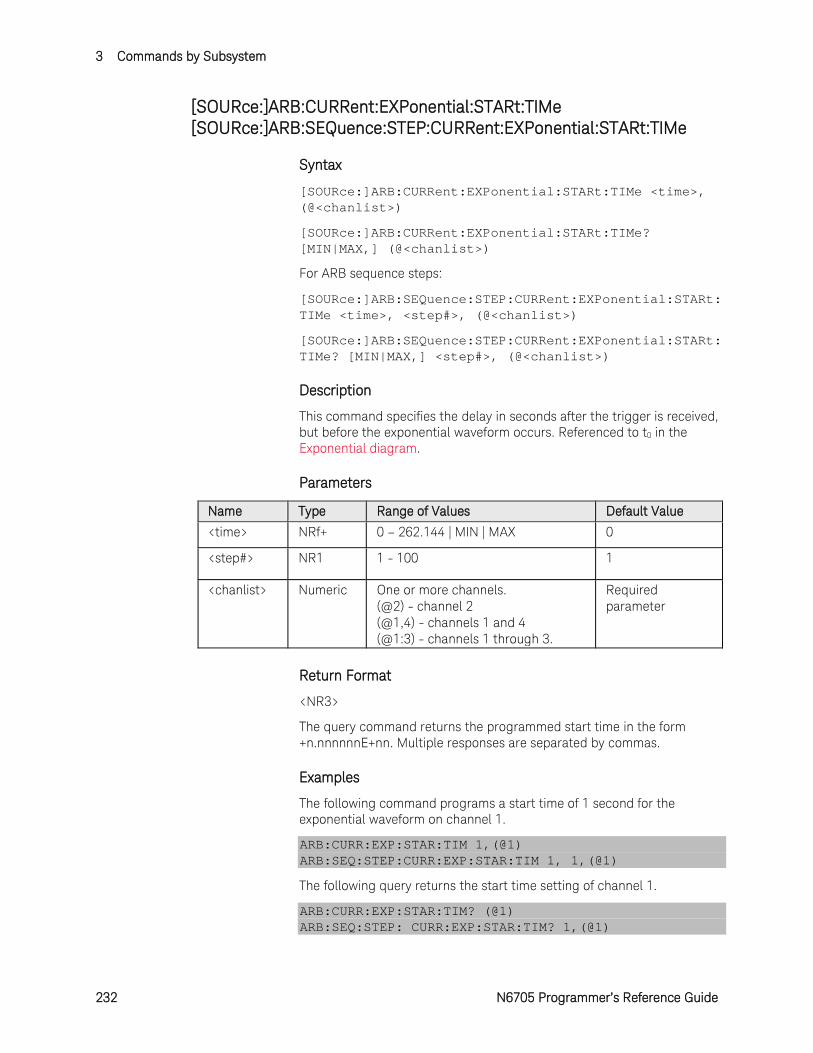
3 Commands by Subsystem
232 N6705 Programmer’s Reference Guide
[SOURce:]ARB:CURRent:EXPonential:STARt:TIMe [SOURce:]ARB:SEQuence:STEP:CURRent:EXPonential:STARt:TIMe
Syntax
[SOURce:]ARB:CURRent:EXPonential:STARt:TIMe <time>, (@<chanlist>)
[SOURce:]ARB:CURRent:EXPonential:STARt:TIMe? [MIN|MAX,] (@<chanlist>)
For ARB sequence steps:
[SOURce:]ARB:SEQuence:STEP:CURRent:EXPonential:STARt:TIMe <time>, <step#>, (@<chanlist>)
[SOURce:]ARB:SEQuence:STEP:CURRent:EXPonential:STARt:TIMe? [MIN|MAX,] <step#>, (@<chanlist>)
Description
This command specifies the delay in seconds after the trigger is received, but before the exponential waveform occurs. Referenced to t0 in the Exponential diagram.
Parameters
Name Type Range of Values Default Value
<time> NRf+ 0 – 262.144 | MIN | MAX 0
<step#> NR1 1 - 100 1
<chanlist> Numeric One or more channels. (@2) - channel 2 (@1,4) - channels 1 and 4 (@1:3) - channels 1 through 3.
Required parameter
Return Format
<NR3>
The query command returns the programmed start time in the form +n.nnnnnnE+nn. Multiple responses are separated by commas.
Examples
The following command programs a start time of 1 second for the exponential waveform on channel 1.
ARB:CURR:EXP:STAR:TIM 1,(@1) ARB:SEQ:STEP:CURR:EXP:STAR:TIM 1, 1,(@1)
The following query returns the start time setting of channel 1.
ARB:CURR:EXP:STAR:TIM? (@1) ARB:SEQ:STEP: CURR:EXP:STAR:TIM? 1,(@1)
Commands by Subsystem 3
N6705 Programmer’s Reference Guide 233
Typical Response: +1.000000E+00
See Also
[SOURce:]ARB:CURRent:EXPonential:STARt[:LEVel]
[SOURce:]ARB:CURRent:EXPonential:TIMe
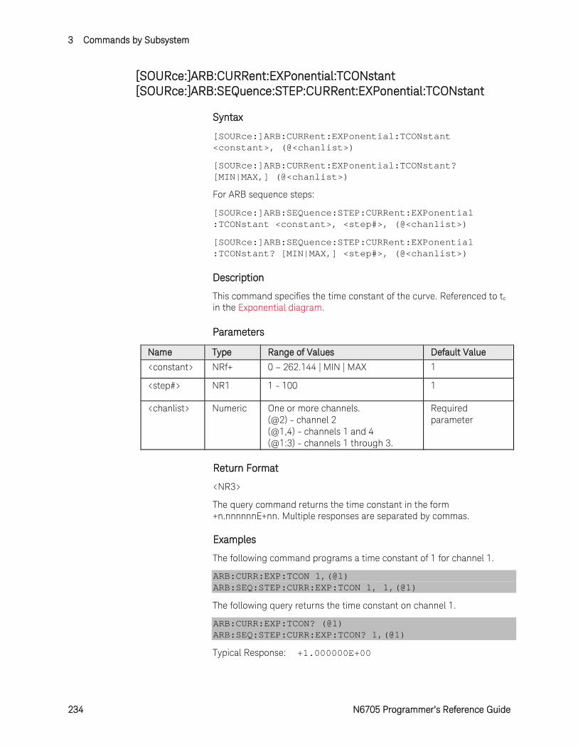
3 Commands by Subsystem
234 N6705 Programmer’s Reference Guide
[SOURce:]ARB:CURRent:EXPonential:TCONstant [SOURce:]ARB:SEQuence:STEP:CURRent:EXPonential:TCONstant
Syntax
[SOURce:]ARB:CURRent:EXPonential:TCONstant <constant>, (@<chanlist>)
[SOURce:]ARB:CURRent:EXPonential:TCONstant? [MIN|MAX,] (@<chanlist>)
For ARB sequence steps:
[SOURce:]ARB:SEQuence:STEP:CURRent:EXPonential :TCONstant <constant>, <step#>, (@<chanlist>)
[SOURce:]ARB:SEQuence:STEP:CURRent:EXPonential :TCONstant? [MIN|MAX,] <step#>, (@<chanlist>)
Description
This command specifies the time constant of the curve. Referenced to tc in the Exponential diagram.
Parameters
Name Type Range of Values Default Value
<constant> NRf+ 0 – 262.144 | MIN | MAX 1
<step#> NR1 1 - 100 1
<chanlist> Numeric One or more channels. (@2) - channel 2 (@1,4) - channels 1 and 4 (@1:3) - channels 1 through 3.
Required parameter
Return Format
<NR3>
The query command returns the time constant in the form +n.nnnnnnE+nn. Multiple responses are separated by commas.
Examples
The following command programs a time constant of 1 for channel 1.
ARB:CURR:EXP:TCON 1,(@1) ARB:SEQ:STEP:CURR:EXP:TCON 1, 1,(@1)
The following query returns the time constant on channel 1.
ARB:CURR:EXP:TCON? (@1) ARB:SEQ:STEP:CURR:EXP:TCON? 1,(@1)
Typical Response: +1.000000E+00
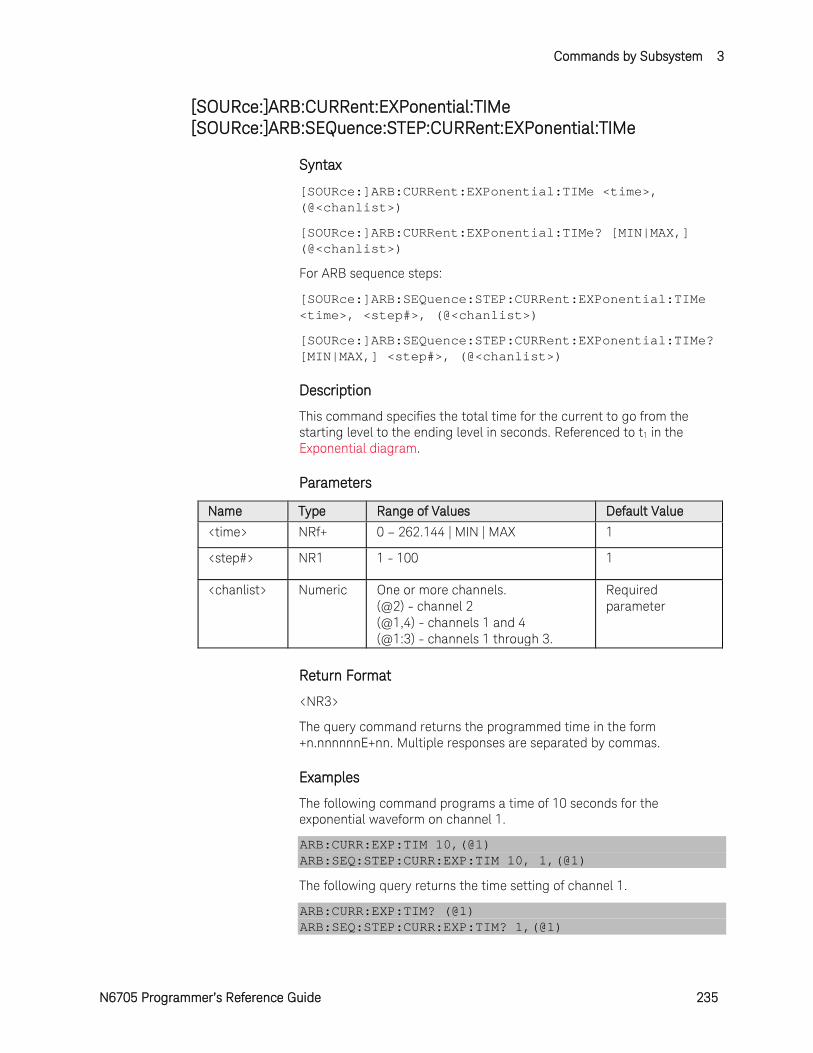
Commands by Subsystem 3
N6705 Programmer’s Reference Guide 235
[SOURce:]ARB:CURRent:EXPonential:TIMe [SOURce:]ARB:SEQuence:STEP:CURRent:EXPonential:TIMe
Syntax
[SOURce:]ARB:CURRent:EXPonential:TIMe <time>, (@<chanlist>)
[SOURce:]ARB:CURRent:EXPonential:TIMe? [MIN|MAX,] (@<chanlist>)
For ARB sequence steps:
[SOURce:]ARB:SEQuence:STEP:CURRent:EXPonential:TIMe <time>, <step#>, (@<chanlist>)
[SOURce:]ARB:SEQuence:STEP:CURRent:EXPonential:TIMe? [MIN|MAX,] <step#>, (@<chanlist>)
Description
This command specifies the total time for the current to go from the starting level to the ending level in seconds. Referenced to t1 in the Exponential diagram.
Parameters
Name Type Range of Values Default Value
<time> NRf+ 0 – 262.144 | MIN | MAX 1
<step#> NR1 1 - 100 1
<chanlist> Numeric One or more channels. (@2) - channel 2 (@1,4) - channels 1 and 4 (@1:3) - channels 1 through 3.
Required parameter
Return Format
<NR3>
The query command returns the programmed time in the form +n.nnnnnnE+nn. Multiple responses are separated by commas.
Examples
The following command programs a time of 10 seconds for the exponential waveform on channel 1.
ARB:CURR:EXP:TIM 10,(@1) ARB:SEQ:STEP:CURR:EXP:TIM 10, 1,(@1)
The following query returns the time setting of channel 1.
ARB:CURR:EXP:TIM? (@1) ARB:SEQ:STEP:CURR:EXP:TIM? 1,(@1)
3 Commands by Subsystem
236 N6705 Programmer’s Reference Guide
Typical Response: +1.000000E+00
See Also
[SOURce:]ARB:CURRent:EXPonential:STARt:TIMe

Commands by Subsystem 3
N6705 Programmer’s Reference Guide 237
[SOURce:]ARB:CURRent:PULSe:END:TIMe [SOURce:]ARB:SEQuence:STEP:CURRent:PULSe:END:TIMe
Syntax
[SOURce:]ARB:CURRent:PULSe:END:TIMe <time>, (@<chanlist>)
[SOURce:]ARB:CURRent:PULSe:END:TIMe? [MIN|MAX,] (@<chanlist>)
For ARB sequence steps:
[SOURce:]ARB:SEQuence:STEP:CURRent:PULSe:END:TIMe <time>, <step#>, (@<chanlist>)
[SOURce:]ARB:SEQuence:STEP:CURRent:PULSe:END:TIMe? [MIN|MAX,] <step#>, (@<chanlist>)
Description
This command specifies the time in seconds, after the pulse completes, that the start-level current persists. Referenced to t2 in the Pulse diagram.
Parameters
Name Type Range of Values Default Value
<time> NRf+ 0 – 262.144 | MIN | MAX 0
<step#> NR1 1 - 100 1
<chanlist> Numeric One or more channels. (@2) - channel 2 (@1,4) - channels 1 and 4 (@1:3) - channels 1 through 3.
Required parameter
Return Format
<NR3>
The query command returns the programmed end time in the form +n.nnnnnnE+nn. Multiple responses are separated by commas.
Examples
The following command programs an end time of 1 second after the pulse on channel 1.
ARB:CURR:PULS:END:TIM 1,(@1) ARB:SEQ:STEP:CURR:PULS:END:TIM 1, 1,(@1)
The following query returns the end time setting of channel 1.
ARB:CURR:PULS:END:TIM? (@1) ARB:SEQ:STEP:CURR:PULS:END:TIM? 1,(@1)
Typical Response: +1.000000E+00
3 Commands by Subsystem
238 N6705 Programmer’s Reference Guide
See Also
[SOURce:]ARB:CURRent:PULSe:STARt[:LEVel]
[SOURce:]ARB:CURRent:PULSe:STARt:TIMe
[SOURce:]ARB:CURRent:PULSe:TOP:TIMe

Commands by Subsystem 3
N6705 Programmer’s Reference Guide 239
[SOURce:]ARB:CURRent:PULSe:STARt[:LEVel] [SOURce:]ARB:SEQuence:STEP:CURRent:PULSe:STARt[:LEVel]
Syntax
[SOURce:]ARB:CURRent:PULSe:STARt[:LEVel] <current>, (@<chanlist>)
[SOURce:]ARB:CURRent:PULSe:STARt[:LEVel]? [MIN|MAX,] (@<chanlist>)
For ARB sequence steps:
[SOURce:]ARB:SEQuence:STEP:CURRent:PULSe:STARt [:LEVel] <current>, <step#>, (@<chanlist>)
[SOURce:]ARB:SEQuence:STEP:CURRent:PULSe:STARt [:LEVel]? [MIN|MAX,] <step#>, (@<chanlist>)
Description
This command specifies the current before and after the pulse occurs in amperes. Referenced to I0 in the Pulse diagram.
Parameters
Name Type Range of Values Default Value
<current> NRf+ 0 - maximum | MIN | MAX The maximum value is dependent on the current rating of the power module.
MIN
<step#> NR1 1 - 100 1
<chanlist> Numeric One or more channels. (@2) - channel 2 (@1,4) - channels 1 and 4 (@1:3) - channels 1 through 3.
Required parameter
Return Format
<NR3>
The query command returns the programmed current level in the form +n.nnnnnnE+nn. Multiple responses are separated by commas.
Examples
The following command programs a starting and ending current level for the pulse on channel 1.
ARB:CURR:PULS:STAR 1,(@1) ARB:SEQ:STEP:CURR:PULS:STAR 1, 1,(@1)
The following query returns the starting and ending current setting of channel 1.

3 Commands by Subsystem
240 N6705 Programmer’s Reference Guide
ARB:CURR:PULS:STAR? (@1) ARB:SEQ:STEP:CURR:PULS:STAR? 1,(@1)
Typical Response: +1.000000E+00
See Also
[SOURce:]ARB:CURRent:PULSe:STARt:TIMe
[SOURce:]ARB:CURRent:PULse:TOP[:LEVel]
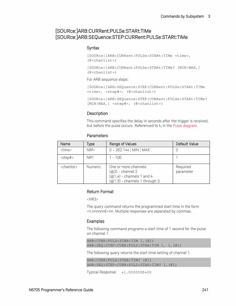
Commands by Subsystem 3
N6705 Programmer’s Reference Guide 241
[SOURce:]ARB:CURRent:PULSe:STARt:TIMe [SOURce:]ARB:SEQuence:STEP:CURRent:PULSe:STARt:TIMe
Syntax
[SOURce:]ARB:CURRent:PULSe:STARt:TIMe <time>, (@<chanlist>)
[SOURce:]ARB:CURRent:PULSe:STARt:TIMe? [MIN|MAX,] (@<chanlist>)
For ARB sequence steps:
[SOURce:]ARB:SEQuence:STEP:CURRent:PULSe:STARt:TIMe <time>, <step#>, (@<chanlist>)
[SOURce:]ARB:SEQuence:STEP:CURRent:PULSe:STARt:TIMe? [MIN|MAX,] <step#>, (@<chanlist>)
Description
This command specifies the delay in seconds after the trigger is received, but before the pulse occurs. Referenced to t0 in the Pulse diagram.
Parameters
Name Type Range of Values Default Value
<time> NRf+ 0 – 262.144 | MIN | MAX 0
<step#> NR1 1 - 100 1
<chanlist> Numeric One or more channels. (@2) - channel 2 (@1,4) - channels 1 and 4 (@1:3) - channels 1 through 3.
Required parameter
Return Format
<NR3>
The query command returns the programmed start time in the form +n.nnnnnnE+nn. Multiple responses are separated by commas.
Examples
The following command programs a start time of 1 second for the pulse on channel 1.
ARB:CURR:PULS:STAR:TIM 1,(@1) ARB:SEQ:STEP:CURR:PULS:STAR:TIM 1, 1,(@1)
The following query returns the start time setting of channel 1.
ARB:CURR:PULS:STAR:TIM? (@1) ARB:SEQ:STEP:CURR:PULS:STAR:TIM? 1,(@1)
Typical Response: +1.000000E+00
3 Commands by Subsystem
242 N6705 Programmer’s Reference Guide
See Also
[SOURce:]ARB:CURRent:PULSe:STARt[:LEVel]
[SOURce:]ARB:CURRent:PULSe:END:TIMe
[SOURce:]ARB:CURRent:PULSe:TOP:TIMe

Commands by Subsystem 3
N6705 Programmer’s Reference Guide 243
[SOURce:]ARB:CURRent:PULSe:TOP[:LEVel] [SOURce:]ARB:SEQuence:STEP:CURRent:PULSe:TOP[:LEVel]
Syntax
[SOURce:]ARB:CURRent:PULSe:TOP[:LEVel] <current>, (@<chanlist>)
[SOURce:]ARB:CURRent:PULSe:TOP[:LEVel]? [MIN|MAX,] (@<chanlist>)
For ARB sequence steps:
[SOURce:]ARB:SEQuence:STEP:CURRent:PULSe:TOP[:LEVel] <current>, <step#>, (@<chanlist>)
[SOURce:]ARB:SEQuence:STEP:CURRent:PULSe:TOP[:LEVel]? [MIN|MAX,] <step#>, (@<chanlist>)
Description
This command specifies the top level current of the pulse in amperes. Referenced to I1 in the Pulse diagram.
Parameters
Name Type Range of Values Default Value
<current> NRf+ 0 - maximum | MIN | MAX The maximum value is dependent on the current rating of the power module.
MIN
<step#> NR1 1 - 100 1
<chanlist> Numeric One or more channels. (@2) - channel 2 (@1,4) - channels 1 and 4 (@1:3) - channels 1 through 3.
Required parameter
Return Format
<NR3>
The query command returns the programmed current level in the form +n.nnnnnnE+nn. Multiple responses are separated by commas.
Examples
The following command programs a top level current for the pulse on channel 1.
ARB:CURR:PULS:TOP 2,(@1) ARB:SEQ:STEP:CURR:PULS:TOP 2, 1,(@1)
The following query returns the top level current setting of channel 1.

3 Commands by Subsystem
244 N6705 Programmer’s Reference Guide
ARB:CURR:PULS:TOP? (@1) ARB:SEQ:STEP:CURR:PULS:TOP? 1,(@1)
Typical Response: +2.000000E+00
See Also
[SOURce:]ARB:CURRent:PULSe:STARt[:LEVel]
[SOURce:]ARB:CURRent:PULSe:TOP:TIMe

Commands by Subsystem 3
N6705 Programmer’s Reference Guide 245
[SOURce:]ARB:CURRent:PULSe:TOP:TIMe [SOURce:]ARB:SEQuence:STEP:CURRent:PULSe:TOP:TIMe
Syntax
[SOURce:]ARB:CURRent:PULSe:TOP:TIMe <time>, (@<chanlist>)
[SOURce:]ARB:CURRent:PULSe:TOP:TIMe? [MIN|MAX,] (@<chanlist>)
For ARB sequence steps:
[SOURce:]ARB:SEQuence:STEP:CURRent:PULSe:TOP:TIMe <time>, <step#>, (@<chanlist>)
[SOURce:]ARB:SEQuence:STEP:CURRent:PULSe:TOP:TIMe? [MIN|MAX,] <step#>, (@<chanlist>)
Description
This command specifies the time of the pulse in seconds. Referenced to t1 in the Pulse diagram.
Parameters
Name Type Range of Values Default Value
<time> NRf+ 0 – 262.144 | MIN | MAX 1
<step#> NR1 1 - 100 1
<chanlist> Numeric One or more channels. (@2) - channel 2 (@1,4) - channels 1 and 4 (@1:3) - channels 1 through 3.
Required parameter
Return Format
<NR3>
The query command returns the programmed top time in the form +n.nnnnnnE+nn. Multiple responses are separated by commas.
Examples
The following command programs a top (pulse) time of 1 second on channel 1.
ARB:CURR:PULS:TOP:TIM 1,(@1) ARB:SEQ:STEP:CURR:PULS:TOP:TIM 1, 1,(@1)
The following query returns the top time setting of channel 1.
ARB:CURR:PULS:TOP:TIM? (@1) ARB:SEQ:STEP:CURR:PULS:TOP:TIM? 1,(@1)
Typical Response: +1.000000E+00

3 Commands by Subsystem
246 N6705 Programmer’s Reference Guide
See Also
[SOURce:]ARB:CURRent:PULse:TOP[:LEVel]
[SOURce:]ARB:CURRent:PULSe:STARt:TIMe
[SOURce:]ARB:CURRent:PULSe:END:TIMe
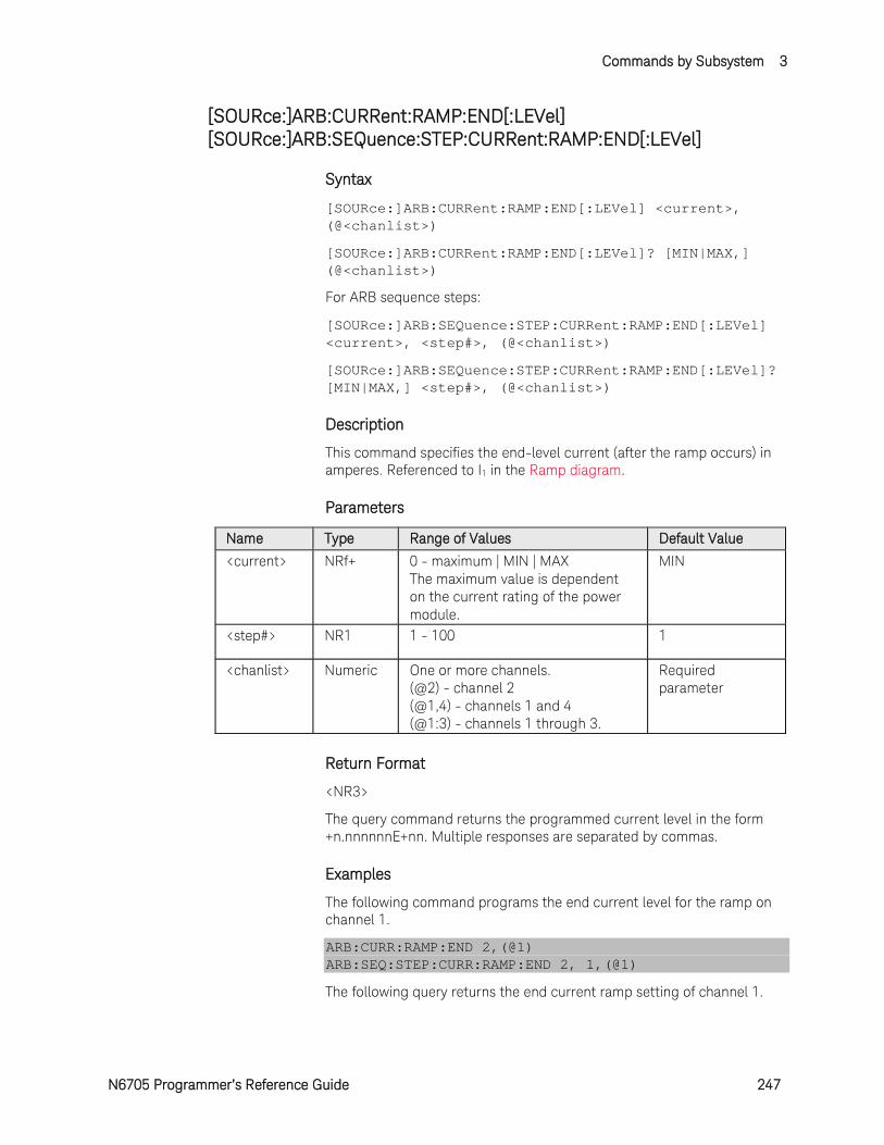
Commands by Subsystem 3
N6705 Programmer’s Reference Guide 247
[SOURce:]ARB:CURRent:RAMP:END[:LEVel] [SOURce:]ARB:SEQuence:STEP:CURRent:RAMP:END[:LEVel]
Syntax
[SOURce:]ARB:CURRent:RAMP:END[:LEVel] <current>, (@<chanlist>)
[SOURce:]ARB:CURRent:RAMP:END[:LEVel]? [MIN|MAX,] (@<chanlist>)
For ARB sequence steps:
[SOURce:]ARB:SEQuence:STEP:CURRent:RAMP:END[:LEVel] <current>, <step#>, (@<chanlist>)
[SOURce:]ARB:SEQuence:STEP:CURRent:RAMP:END[:LEVel]? [MIN|MAX,] <step#>, (@<chanlist>)
Description
This command specifies the end-level current (after the ramp occurs) in amperes. Referenced to I1 in the Ramp diagram.
Parameters
Name Type Range of Values Default Value
<current> NRf+ 0 - maximum | MIN | MAX The maximum value is dependent on the current rating of the power module.
MIN
<step#> NR1 1 - 100 1
<chanlist> Numeric One or more channels. (@2) - channel 2 (@1,4) - channels 1 and 4 (@1:3) - channels 1 through 3.
Required parameter
Return Format
<NR3>
The query command returns the programmed current level in the form +n.nnnnnnE+nn. Multiple responses are separated by commas.
Examples
The following command programs the end current level for the ramp on channel 1.
ARB:CURR:RAMP:END 2,(@1) ARB:SEQ:STEP:CURR:RAMP:END 2, 1,(@1)
The following query returns the end current ramp setting of channel 1.

3 Commands by Subsystem
248 N6705 Programmer’s Reference Guide
ARB:CURR:RAMP:END? (@1) ARB:SEQ:STEP:CURR:RAMP:END? 1,(@1)
Typical Response: +2.000000E+00
See Also
[SOURce:]ARB:CURRent:RAMP:STARt[:LEVel]
[SOURce:]ARB:CURRent:RAMP:END:TIMe

Commands by Subsystem 3
N6705 Programmer’s Reference Guide 249
[SOURce:]ARB:CURRent:RAMP:END:TIMe [SOURce:]ARB:SEQuence:STEP:CURRent:RAMP:END:TIMe
Syntax
[SOURce:]ARB:CURRent:RAMP:END:TIMe <time>, (@<chanlist>)
[SOURce:]ARB:CURRent:RAMP:END:TIMe? [MIN|MAX,] (@<chanlist>)
For ARB sequence steps:
[SOURce:]ARB:SEQuence:STEP:CURRent:RAMP:END:TIMe <time>, <step#>, (@<chanlist>)
[SOURce:]ARB:SEQuence:STEP:CURRent:RAMP:END:TIMe? [MIN|MAX,] <step#>, (@<chanlist>)
Description
This command specifies the time in seconds, after the ramp completes, that the end-level current persists. Referenced to t2 in the Ramp diagram.
Parameters
Name Type Range of Values Default Value
<time> NRf+ 0 – 262.144 | MIN | MAX 0
<step#> NR1 1 - 100 1
<chanlist> Numeric One or more channels. (@2) - channel 2 (@1,4) - channels 1 and 4 (@1:3) - channels 1 through 3.
Required parameter
Return Format
<NR3>
The query command returns the programmed end time in the form +n.nnnnnnE+nn. Multiple responses are separated by commas.
Examples
The following command programs an end time of 1 second after the ramp on channel 1.
ARB:CURR:RAMP:END:TIM 1,(@1) ARB:SEQ:STEP:CURR:RAMP:END:TIM 1, 1,(@1)
The following query returns the end time setting of channel 1.
ARB:CURR:RAMP:END:TIM? (@1) ARB:SEQ:STEP:CURR:RAMP:END:TIM? 1,(@1)
Typical Response: +1.000000E+00
3 Commands by Subsystem
250 N6705 Programmer’s Reference Guide
See Also
[SOURce:]ARB:CURRent:RAMP:END[:LEVel]
[SOURce:]ARB:CURRent:RAMP:STARt:TIMe
[SOURce:]ARB:CURRent:RAMP:RTIMe
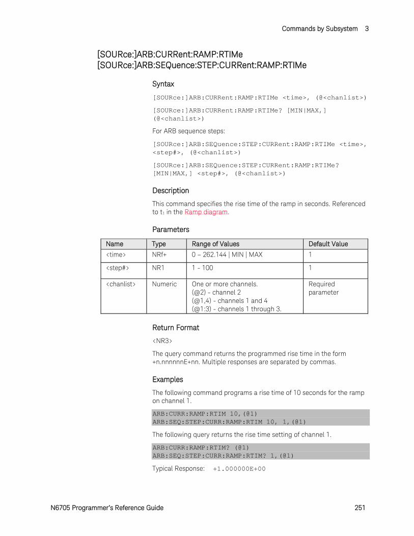
Commands by Subsystem 3
N6705 Programmer’s Reference Guide 251
[SOURce:]ARB:CURRent:RAMP:RTIMe [SOURce:]ARB:SEQuence:STEP:CURRent:RAMP:RTIMe
Syntax
[SOURce:]ARB:CURRent:RAMP:RTIMe <time>, (@<chanlist>)
[SOURce:]ARB:CURRent:RAMP:RTIMe? [MIN|MAX,] (@<chanlist>)
For ARB sequence steps:
[SOURce:]ARB:SEQuence:STEP:CURRent:RAMP:RTIMe <time>, <step#>, (@<chanlist>)
[SOURce:]ARB:SEQuence:STEP:CURRent:RAMP:RTIMe? [MIN|MAX,] <step#>, (@<chanlist>)
Description
This command specifies the rise time of the ramp in seconds. Referenced to t1 in the Ramp diagram.
Parameters
Name Type Range of Values Default Value
<time> NRf+ 0 – 262.144 | MIN | MAX 1
<step#> NR1 1 - 100 1
<chanlist> Numeric One or more channels. (@2) - channel 2 (@1,4) - channels 1 and 4 (@1:3) - channels 1 through 3.
Required parameter
Return Format
<NR3>
The query command returns the programmed rise time in the form +n.nnnnnnE+nn. Multiple responses are separated by commas.
Examples
The following command programs a rise time of 10 seconds for the ramp on channel 1.
ARB:CURR:RAMP:RTIM 10,(@1) ARB:SEQ:STEP:CURR:RAMP:RTIM 10, 1,(@1)
The following query returns the rise time setting of channel 1.
ARB:CURR:RAMP:RTIM? (@1) ARB:SEQ:STEP:CURR:RAMP:RTIM? 1,(@1)
Typical Response: +1.000000E+00
3 Commands by Subsystem
252 N6705 Programmer’s Reference Guide
See Also
[SOURce:]ARB:CURRent:RAMP:STARt:TIMe
[SOURce:]ARB:CURRent:RAMP:END:TIMe
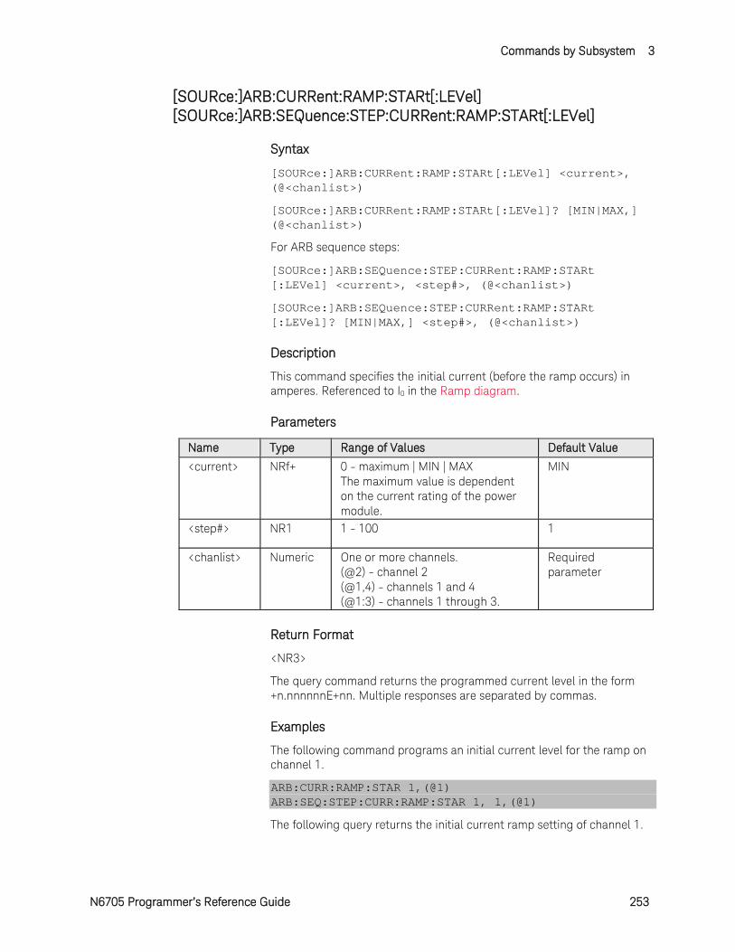
Commands by Subsystem 3
N6705 Programmer’s Reference Guide 253
[SOURce:]ARB:CURRent:RAMP:STARt[:LEVel] [SOURce:]ARB:SEQuence:STEP:CURRent:RAMP:STARt[:LEVel]
Syntax
[SOURce:]ARB:CURRent:RAMP:STARt[:LEVel] <current>, (@<chanlist>)
[SOURce:]ARB:CURRent:RAMP:STARt[:LEVel]? [MIN|MAX,] (@<chanlist>)
For ARB sequence steps:
[SOURce:]ARB:SEQuence:STEP:CURRent:RAMP:STARt [:LEVel] <current>, <step#>, (@<chanlist>)
[SOURce:]ARB:SEQuence:STEP:CURRent:RAMP:STARt [:LEVel]? [MIN|MAX,] <step#>, (@<chanlist>)
Description
This command specifies the initial current (before the ramp occurs) in amperes. Referenced to I0 in the Ramp diagram.
Parameters
Name Type Range of Values Default Value
<current> NRf+ 0 - maximum | MIN | MAX The maximum value is dependent on the current rating of the power module.
MIN
<step#> NR1 1 - 100 1
<chanlist> Numeric One or more channels. (@2) - channel 2 (@1,4) - channels 1 and 4 (@1:3) - channels 1 through 3.
Required parameter
Return Format
<NR3>
The query command returns the programmed current level in the form +n.nnnnnnE+nn. Multiple responses are separated by commas.
Examples
The following command programs an initial current level for the ramp on channel 1.
ARB:CURR:RAMP:STAR 1,(@1) ARB:SEQ:STEP:CURR:RAMP:STAR 1, 1,(@1)
The following query returns the initial current ramp setting of channel 1.
3 Commands by Subsystem
254 N6705 Programmer’s Reference Guide
ARB:CURR:RAMP:STAR? (@1) ARB:SEQ:STEP:CURR:RAMP:STAR? 1,(@1)
Typical Response: +1.000000E+00
See Also
[SOURce:]ARB:CURRent:RAMP:STARt:TIMe
[SOURce:]ARB:CURRent:RAMP:END[:LEVel]

Commands by Subsystem 3
N6705 Programmer’s Reference Guide 255
[SOURce:]ARB:CURRent:RAMP:STARt:TIMe [SOURce:]ARB:SEQuence:STEP:CURRent:RAMP:STARt:TIMe
Syntax
[SOURce:]ARB:CURRent:RAMP:STARt:TIMe <time>, (@<chanlist>)
[SOURce:]ARB:CURRent:RAMP:STARt:TIMe? [MIN|MAX,] (@<chanlist>)
For ARB sequence steps:
[SOURce:]ARB:SEQuence:STEP:CURRent:RAMP:STARt:TIMe <time>, <step#>, (@<chanlist>)
[SOURce:]ARB:SEQuence:STEP:CURRent:RAMP:STARt:TIMe? [MIN|MAX,] <step#>, (@<chanlist>)
Description
This command specifies the delay in seconds after the trigger is received, but before the ramp occurs. Referenced to t0 in the Ramp diagram.
Parameters
Name Type Range of Values Default Value
<time> NRf+ 0 – 262.144 | MIN | MAX 0
<step#> NR1 1 - 100 1
<chanlist> Numeric One or more channels. (@2) - channel 2 (@1,4) - channels 1 and 4 (@1:3) - channels 1 through 3.
Required parameter
Return Format
<NR3>
The query command returns the programmed start time in the form +n.nnnnnnE+nn. Multiple responses are separated by commas.
Examples
The following command programs a start time of 1 second for the ramp on channel 1.
ARB:CURR:RAMP:STAR:TIM 1,(@1) ARB:SEQ:STEP:CURR:RAMP:STAR:TIM 1, 1,(@1)
The following query returns the start time setting of channel 1.
ARB:CURR:RAMP:STAR:TIM? (@1) ARB:SEQ:STEP:CURR:RAMP:STAR:TIM? 1,(@1)
Typical Response: +1.000000E+00
3 Commands by Subsystem
256 N6705 Programmer’s Reference Guide
See Also
[SOURce:]ARB:CURRent:RAMP:STARt[:LEVel]
[SOURce:]ARB:CURRent:RAMP:END:TIMe
[SOURce:]ARB:CURRent:RAMP:RTIMe
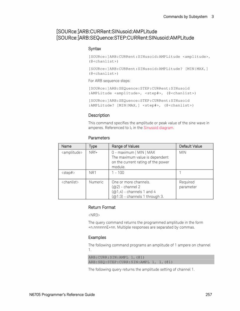
Commands by Subsystem 3
N6705 Programmer’s Reference Guide 257
[SOURce:]ARB:CURRent:SINusoid:AMPLitude [SOURce:]ARB:SEQuence:STEP:CURRent:SINusoid:AMPLitude
Syntax
[SOURce:]ARB:CURRent:SINusoid:AMPLitude <amplitude>, (@<chanlist>)
[SOURce:]ARB:CURRent:SINusoid:AMPLitude? [MIN|MAX,] (@<chanlist>)
For ARB sequence steps:
[SOURce:]ARB:SEQuence:STEP:CURRent:SINusoid :AMPLitude <amplitude>, <step#>, (@<chanlist>)
[SOURce:]ARB:SEQuence:STEP:CURRent:SINusoid :AMPLitude? [MIN|MAX,] <step#>, (@<chanlist>)
Description
This command specifies the amplitude or peak value of the sine wave in amperes. Referenced to I0 in the Sinusoid diagram.
Parameters
Name Type Range of Values Default Value
<amplitude> NRf+ 0 - maximum | MIN | MAX The maximum value is dependent on the current rating of the power module.
MIN
<step#> NR1 1 - 100 1
<chanlist> Numeric One or more channels. (@2) - channel 2 (@1,4) - channels 1 and 4 (@1:3) - channels 1 through 3.
Required parameter
Return Format
<NR3>
The query command returns the programmed amplitude in the form +n.nnnnnnE+nn. Multiple responses are separated by commas.
Examples
The following command programs an amplitude of 1 ampere on channel 1.
ARB:CURR:SIN:AMPL 1,(@1) ARB:SEQ:STEP:CURR:SIN:AMPL 1, 1,(@1)
The following query returns the amplitude setting of channel 1.
3 Commands by Subsystem
258 N6705 Programmer’s Reference Guide
ARB:CURR:SIN:AMPL? (@1) ARB:SEQ:STEP:CURR:SIN:AMPL? 1,(@1)
Typical Response: +1.000000E+01
See Also
[SOURce:]ARB:CURRent:SINusoid:OFFSet
[SOURce:]ARB:CURRent:SINusoid:FREQuency
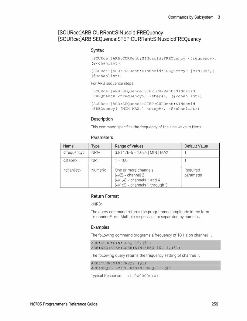
Commands by Subsystem 3
N6705 Programmer’s Reference Guide 259
[SOURce:]ARB:CURRent:SINusoid:FREQuency [SOURce:]ARB:SEQuence:STEP:CURRent:SINusoid:FREQuency
Syntax
[SOURce:]ARB:CURRent:SINusoid:FREQuency <frequency>, (@<chanlist>)
[SOURce:]ARB:CURRent:SINusoid:FREQuency? [MIN|MAX,] (@<chanlist>)
For ARB sequence steps:
[SOURce:]ARB:SEQuence:STEP:CURRent:SINusoid :FREQuency <frequency>, <step#>, (@<chanlist>)
[SOURce:]ARB:SEQuence:STEP:CURRent:SINusoid :FREQuency? [MIN|MAX,] <step#>, (@<chanlist>)
Description
This command specifies the frequency of the sine wave in Hertz.
Parameters
Name Type Range of Values Default Value
<frequency> NRf+ 3.8147E-5 - 1.0E4 | MIN | MAX 1
<step#> NR1 1 - 100 1
<chanlist> Numeric One or more channels. (@2) - channel 2 (@1,4) - channels 1 and 4 (@1:3) - channels 1 through 3.
Required parameter
Return Format
<NR3>
The query command returns the programmed amplitude in the form +n.nnnnnnE+nn. Multiple responses are separated by commas.
Examples
The following command programs a frequency of 10 Hz on channel 1.
ARB:CURR:SIN:FREQ 10,(@1) ARB:SEQ:STEP:CURR:SIN:FREQ 10, 1,(@1)
The following query returns the frequency setting of channel 1.
ARB:CURR:SIN:FREQ? (@1) ARB:SEQ:STEP:CURR:SIN:FREQ? 1,(@1)
Typical Response: +1.000000E+01

3 Commands by Subsystem
260 N6705 Programmer’s Reference Guide
See Also
[SOURce:]ARB:CURRent:SINusoid:AMPLitude
[SOURce:]ARB:CURRent:SINusoid:OFFSet
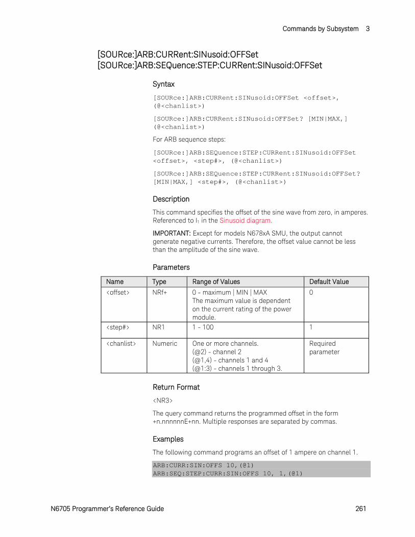
Commands by Subsystem 3
N6705 Programmer’s Reference Guide 261
[SOURce:]ARB:CURRent:SINusoid:OFFSet [SOURce:]ARB:SEQuence:STEP:CURRent:SINusoid:OFFSet
Syntax
[SOURce:]ARB:CURRent:SINusoid:OFFSet <offset>, (@<chanlist>)
[SOURce:]ARB:CURRent:SINusoid:OFFSet? [MIN|MAX,] (@<chanlist>)
For ARB sequence steps:
[SOURce:]ARB:SEQuence:STEP:CURRent:SINusoid:OFFSet <offset>, <step#>, (@<chanlist>)
[SOURce:]ARB:SEQuence:STEP:CURRent:SINusoid:OFFSet? [MIN|MAX,] <step#>, (@<chanlist>)
Description
This command specifies the offset of the sine wave from zero, in amperes. Referenced to I1 in the Sinusoid diagram.
IMPORTANT: Except for models N678xA SMU, the output cannot generate negative currents. Therefore, the offset value cannot be less than the amplitude of the sine wave.
Parameters
Name Type Range of Values Default Value
<offset> NRf+ 0 - maximum | MIN | MAX The maximum value is dependent on the current rating of the power module.
0
<step#> NR1 1 - 100 1
<chanlist> Numeric One or more channels. (@2) - channel 2 (@1,4) - channels 1 and 4 (@1:3) - channels 1 through 3.
Required parameter
Return Format
<NR3>
The query command returns the programmed offset in the form +n.nnnnnnE+nn. Multiple responses are separated by commas.
Examples
The following command programs an offset of 1 ampere on channel 1.
ARB:CURR:SIN:OFFS 10,(@1) ARB:SEQ:STEP:CURR:SIN:OFFS 10, 1,(@1)
3 Commands by Subsystem
262 N6705 Programmer’s Reference Guide
The following query returns the offset setting of channel 1.
ARB:CURR:SIN:OFFS? (@1) ARB:SEQ:STEP:CURR:SIN:OFFS? 1,(@1)
Typical Response: +1.000000E+01
See Also
[SOURce:]ARB:CURRent:SINusoid:AMPLitude
[SOURce:]ARB:CURRent:SINusoid:FREQuency
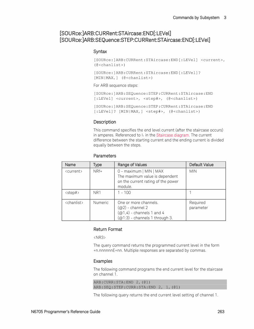
Commands by Subsystem 3
N6705 Programmer’s Reference Guide 263
[SOURce:]ARB:CURRent:STAircase:END[:LEVel] [SOURce:]ARB:SEQuence:STEP:CURRent:STAircase:END[:LEVel]
Syntax
[SOURce:]ARB:CURRent:STAircase:END[:LEVel] <current>, (@<chanlist>)
[SOURce:]ARB:CURRent:STAircase:END[:LEVel]? [MIN|MAX,] (@<chanlist>)
For ARB sequence steps:
[SOURce:]ARB:SEQuence:STEP:CURRent:STAircase:END [:LEVel] <current>, <step#>, (@<chanlist>)
[SOURce:]ARB:SEQuence:STEP:CURRent:STAircase:END [:LEVel]? [MIN|MAX,] <step#>, (@<chanlist>)
Description
This command specifies the end level current (after the staircase occurs) in amperes. Referenced to I1 in the Staircase diagram. The current difference between the starting current and the ending current is divided equally between the steps.
Parameters
Name Type Range of Values Default Value
<current> NRf+ 0 - maximum | MIN | MAX The maximum value is dependent on the current rating of the power module.
MIN
<step#> NR1 1 - 100 1
<chanlist> Numeric One or more channels. (@2) - channel 2 (@1,4) - channels 1 and 4 (@1:3) - channels 1 through 3.
Required parameter
Return Format
<NR3>
The query command returns the programmed current level in the form +n.nnnnnnE+nn. Multiple responses are separated by commas.
Examples
The following command programs the end current level for the staircase on channel 1.
ARB:CURR:STA:END 2,(@1) ARB:SEQ:STEP:CURR:STA:END 2, 1,(@1)
The following query returns the end current level setting of channel 1.

3 Commands by Subsystem
264 N6705 Programmer’s Reference Guide
ARB:CURR:STA:END? (@1) ARB:SEQ:STEP:CURR:STA:END? 1,(@1)
Typical Response: +2.000000E+00
See Also
[SOURce:]ARB:CURRent:STAircase:STARt[:LEVel]
[SOURce:]ARB:CURRent:STAircase:END:TIMe
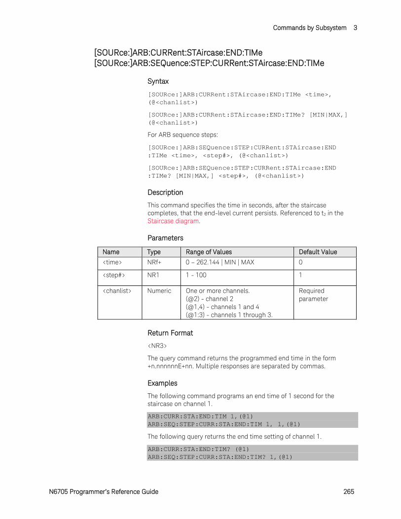
Commands by Subsystem 3
N6705 Programmer’s Reference Guide 265
[SOURce:]ARB:CURRent:STAircase:END:TIMe [SOURce:]ARB:SEQuence:STEP:CURRent:STAircase:END:TIMe
Syntax
[SOURce:]ARB:CURRent:STAircase:END:TIMe <time>, (@<chanlist>)
[SOURce:]ARB:CURRent:STAircase:END:TIMe? [MIN|MAX,] (@<chanlist>)
For ARB sequence steps:
[SOURce:]ARB:SEQuence:STEP:CURRent:STAircase:END :TIMe <time>, <step#>, (@<chanlist>)
[SOURce:]ARB:SEQuence:STEP:CURRent:STAircase:END :TIMe? [MIN|MAX,] <step#>, (@<chanlist>)
Description
This command specifies the time in seconds, after the staircase completes, that the end-level current persists. Referenced to t2 in the Staircase diagram.
Parameters
Name Type Range of Values Default Value
<time> NRf+ 0 – 262.144 | MIN | MAX 0
<step#> NR1 1 - 100 1
<chanlist> Numeric One or more channels. (@2) - channel 2 (@1,4) - channels 1 and 4 (@1:3) - channels 1 through 3.
Required parameter
Return Format
<NR3>
The query command returns the programmed end time in the form +n.nnnnnnE+nn. Multiple responses are separated by commas.
Examples
The following command programs an end time of 1 second for the staircase on channel 1.
ARB:CURR:STA:END:TIM 1,(@1) ARB:SEQ:STEP:CURR:STA:END:TIM 1, 1,(@1)
The following query returns the end time setting of channel 1.
ARB:CURR:STA:END:TIM? (@1) ARB:SEQ:STEP:CURR:STA:END:TIM? 1,(@1)
3 Commands by Subsystem
266 N6705 Programmer’s Reference Guide
Typical Response: +1.000000E+00
See Also
[SOURce:]ARB:CURRent:STAircase:END[:LEVel]
[SOURce:]ARB:CURRent:STAircase:STARt:TIMe
[SOURce:]ARB:CURRent:STAircase:TIMe
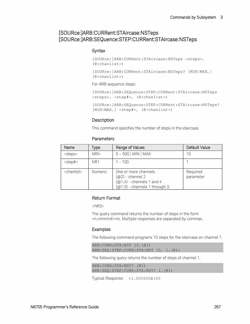
Commands by Subsystem 3
N6705 Programmer’s Reference Guide 267
[SOURce:]ARB:CURRent:STAircase:NSTeps [SOURce:]ARB:SEQuence:STEP:CURRent:STAircase:NSTeps
Syntax
[SOURce:]ARB:CURRent:STAircase:NSTeps <steps>, (@<chanlist>)
[SOURce:]ARB:CURRent:STAircase:NSTeps? [MIN|MAX,] (@<chanlist>)
For ARB sequence steps:
[SOURce:]ARB:SEQuence:STEP:CURRent:STAircase:NSTeps <steps>, <step#>, (@<chanlist>)
[SOURce:]ARB:SEQuence:STEP:CURRent:STAircase:NSTeps? [MIN|MAX,] <step#>, (@<chanlist>)
Description
This command specifies the number of steps in the staircase.
Parameters
Name Type Range of Values Default Value
<steps> NRf+ 0 – 500 | MIN | MAX 10
<step#> NR1 1 - 100 1
<chanlist> Numeric One or more channels. (@2) - channel 2 (@1,4) - channels 1 and 4 (@1:3) - channels 1 through 3.
Required parameter
Return Format
<NR3>
The query command returns the number of steps in the form +n.nnnnnnE+nn. Multiple responses are separated by commas.
Examples
The following command programs 10 steps for the staircase on channel 1.
ARB:CURR:STA:NST 10,(@1) ARB:SEQ:STEP:CURR:STA:NST 10, 1,(@1)
The following query returns the number of steps of channel 1.
ARB:CURR:STA:NST? (@1) ARB:SEQ:STEP:CURR:STA:NST? 1,(@1)
Typical Response: +1.000000E+00
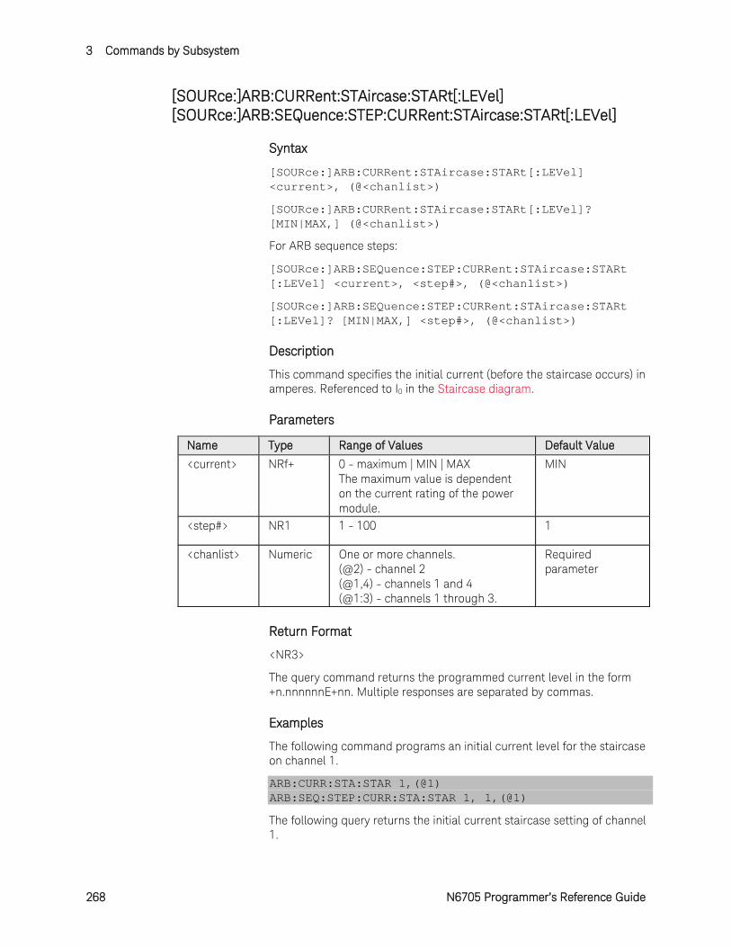
3 Commands by Subsystem
268 N6705 Programmer’s Reference Guide
[SOURce:]ARB:CURRent:STAircase:STARt[:LEVel] [SOURce:]ARB:SEQuence:STEP:CURRent:STAircase:STARt[:LEVel]
Syntax
[SOURce:]ARB:CURRent:STAircase:STARt[:LEVel] <current>, (@<chanlist>)
[SOURce:]ARB:CURRent:STAircase:STARt[:LEVel]? [MIN|MAX,] (@<chanlist>)
For ARB sequence steps:
[SOURce:]ARB:SEQuence:STEP:CURRent:STAircase:STARt [:LEVel] <current>, <step#>, (@<chanlist>)
[SOURce:]ARB:SEQuence:STEP:CURRent:STAircase:STARt [:LEVel]? [MIN|MAX,] <step#>, (@<chanlist>)
Description
This command specifies the initial current (before the staircase occurs) in amperes. Referenced to I0 in the Staircase diagram.
Parameters
Name Type Range of Values Default Value
<current> NRf+ 0 - maximum | MIN | MAX The maximum value is dependent on the current rating of the power module.
MIN
<step#> NR1 1 - 100 1
<chanlist> Numeric One or more channels. (@2) - channel 2 (@1,4) - channels 1 and 4 (@1:3) - channels 1 through 3.
Required parameter
Return Format
<NR3>
The query command returns the programmed current level in the form +n.nnnnnnE+nn. Multiple responses are separated by commas.
Examples
The following command programs an initial current level for the staircase on channel 1.
ARB:CURR:STA:STAR 1,(@1) ARB:SEQ:STEP:CURR:STA:STAR 1, 1,(@1)
The following query returns the initial current staircase setting of channel 1.

Commands by Subsystem 3
N6705 Programmer’s Reference Guide 269
ARB:CURR:STA:STAR? (@1) ARB:SEQ:STEP:CURR:STA:STAR? 1,(@1)
Typical Response: +1.000000E+00
See Also
[SOURce:]ARB:CURRent:STAircase:END[:LEVel]
[SOURce:]ARB:CURRent:STAircase:STARt:TIMe

3 Commands by Subsystem
270 N6705 Programmer’s Reference Guide
[SOURce:]ARB:CURRent:STAircase:STARt:TIMe [SOURce:]ARB:SEQuence:STEP:CURRent:STEP:STARt:TIMe
Syntax
[SOURce:]ARB:CURRent:STAircase:STARt:TIMe <time>, (@<chanlist>)
[SOURce:]ARB:CURRent:STAircase:STARt:TIMe? [MIN|MAX,] (@<chanlist>)
For ARB sequence steps:
[SOURce:]ARB:SEQuence:STEP:CURRent:STEP:STARt:TIMe <time>, <step#>, (@<chanlist>)
[SOURce:]ARB:SEQuence:STEP:CURRent:STEP:STARt:TIMe? [MIN|MAX,] <step#>, (@<chanlist>)
Description
This command specifies the delay in seconds after the trigger is received, but before the staircase occurs. Referenced to t0 in the Staircase diagram.
Parameters
Name Type Range of Values Default Value
<time> NRf+ 0 – 262.144 | MIN | MAX 0
<step#> NR1 1 - 100 1
<chanlist> Numeric One or more channels. (@2) - channel 2 (@1,4) - channels 1 and 4 (@1:3) - channels 1 through 3.
Required parameter
Return Format
<NR3>
The query command returns the programmed start time in the form +n.nnnnnnE+nn. Multiple responses are separated by commas.
Examples
The following command programs a start time of 1 second for the staircase on channel 1.
ARB:CURR:STA:STAR:TIM 1,(@1) ARB:SEQ:STEP:CURR:STA:STAR:TIM 1, 1,(@1)
The following query returns the start time setting of channel 1.
ARB:CURR:STA:STAR:TIM? (@1) ARB:SEQ:STEP:CURR:STA:STAR:TIM? 1,(@1)
Typical Response: +1.000000E+00
Commands by Subsystem 3
N6705 Programmer’s Reference Guide 271
See Also
[SOURce:]ARB:CURRent:STAircase:STARt[:LEVel]
[SOURce:]ARB:CURRent:STAircase:END:TIMe
[SOURce:]ARB:CURRent:STAircase:TIMe

3 Commands by Subsystem
272 N6705 Programmer’s Reference Guide
[SOURce:]ARB:CURRent:STAircase:TIMe [SOURce:]ARB:SEQuence:STEP:CURRent:STAircase:TIMe
Syntax
[SOURce:]ARB:CURRent:STAircase:TIMe <time>, (@<chanlist>)
[SOURce:]ARB:CURRent:STAircase:TIMe? [MIN|MAX,] (@<chanlist>)
For ARB sequence steps:
[SOURce:]ARB:SEQuence:STEP:CURRent:STAircase:TIMe <time>, <step#>, (@<chanlist>)
[SOURce:]ARB:SEQuence:STEP:CURRent:STAircase:TIMe? [MIN|MAX,] <step#>, (@<chanlist>)
Description
This command specifies the total time to complete all of the staircase steps in seconds. Referenced to t1 in the Staircase diagram. Each step is of equal time.
Parameters
Name Type Range of Values Default Value
<time> NRf+ 0 – 262.144 | MIN | MAX 1
<step#> NR1 1 - 100 1
<chanlist> Numeric One or more channels. (@2) - channel 2 (@1,4) - channels 1 and 4 (@1:3) - channels 1 through 3.
Required parameter
Return Format
<NR3>
The query command returns the programmed time in the form +n.nnnnnnE+nn. Multiple responses are separated by commas.
Examples
The following command programs a time of 10 seconds for the staircase on channel 1.
ARB:CURR:STA:TIM 10,(@1) ARB:SEQ:STEP:CURR:STA:TIM 10, 1,(@1)
The following query returns the time setting of channel 1.
ARB:CURR:STA:TIM? (@1) ARB:SEQ:STEP:CURR:STA:TIM? 1,(@1)
Commands by Subsystem 3
N6705 Programmer’s Reference Guide 273
Typical Response: +1.000000E+01
See Also
[SOURce:]ARB:CURRent:STAircase:STARt:TIMe
[SOURce:]ARB:CURRent:STAircase:END:TIMe
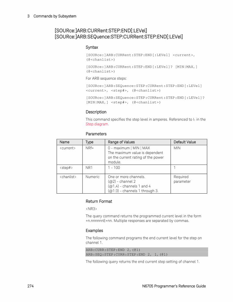
3 Commands by Subsystem
274 N6705 Programmer’s Reference Guide
[SOURce:]ARB:CURRent:STEP:END[:LEVel] [SOURce:]ARB:SEQuence:STEP:CURRent:STEP:END[:LEVel]
Syntax
[SOURce:]ARB:CURRent:STEP:END[:LEVel] <current>, (@<chanlist>)
[SOURce:]ARB:CURRent:STEP:END[:LEVel]? [MIN|MAX,] (@<chanlist>)
For ARB sequence steps:
[SOURce:]ARB:SEQuence:STEP:CURRent:STEP:END[:LEVel] <current>, <step#>, (@<chanlist>)
[SOURce:]ARB:SEQuence:STEP:CURRent:STEP:END[:LEVel]? [MIN|MAX,] <step#>, (@<chanlist>)
Description
This command specifies the step level in amperes. Referenced to I1 in the Step diagram.
Parameters
Name Type Range of Values Default Value
<current> NRf+ 0 - maximum | MIN | MAX The maximum value is dependent on the current rating of the power module.
MIN
<step#> NR1 1 - 100 1
<chanlist> Numeric One or more channels. (@2) - channel 2 (@1,4) - channels 1 and 4 (@1:3) - channels 1 through 3.
Required parameter
Return Format
<NR3>
The query command returns the programmed current level in the form +n.nnnnnnE+nn. Multiple responses are separated by commas.
Examples
The following command programs the end current level for the step on channel 1.
ARB:CURR:STEP:END 2,(@1) ARB:SEQ:STEP:CURR:STEP:END 2, 1,(@1)
The following query returns the end current step setting of channel 1.
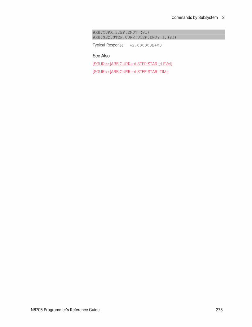
Commands by Subsystem 3
N6705 Programmer’s Reference Guide 275
ARB:CURR:STEP:END? (@1) ARB:SEQ:STEP:CURR:STEP:END? 1,(@1)
Typical Response: +2.000000E+00
See Also
[SOURce:]ARB:CURRent:STEP:STARt[:LEVel]
[SOURce:]ARB:CURRent:STEP:STARt:TIMe
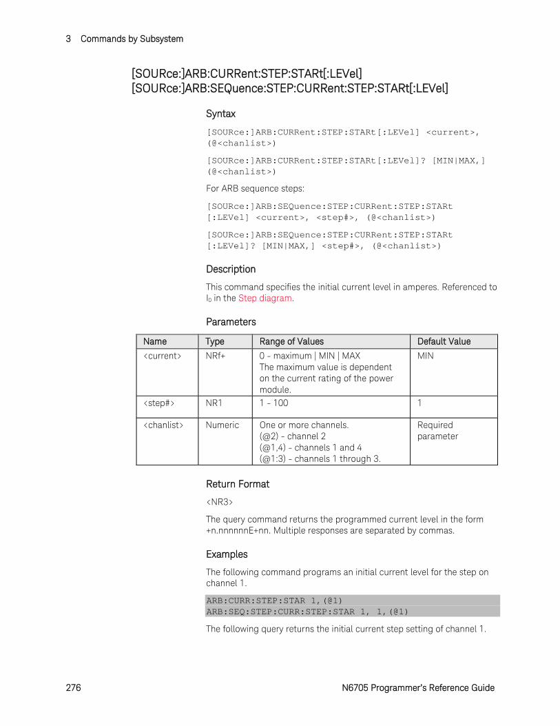
3 Commands by Subsystem
276 N6705 Programmer’s Reference Guide
[SOURce:]ARB:CURRent:STEP:STARt[:LEVel] [SOURce:]ARB:SEQuence:STEP:CURRent:STEP:STARt[:LEVel]
Syntax
[SOURce:]ARB:CURRent:STEP:STARt[:LEVel] <current>, (@<chanlist>)
[SOURce:]ARB:CURRent:STEP:STARt[:LEVel]? [MIN|MAX,] (@<chanlist>)
For ARB sequence steps:
[SOURce:]ARB:SEQuence:STEP:CURRent:STEP:STARt [:LEVel] <current>, <step#>, (@<chanlist>)
[SOURce:]ARB:SEQuence:STEP:CURRent:STEP:STARt [:LEVel]? [MIN|MAX,] <step#>, (@<chanlist>)
Description
This command specifies the initial current level in amperes. Referenced to I0 in the Step diagram.
Parameters
Name Type Range of Values Default Value
<current> NRf+ 0 - maximum | MIN | MAX The maximum value is dependent on the current rating of the power module.
MIN
<step#> NR1 1 - 100 1
<chanlist> Numeric One or more channels. (@2) - channel 2 (@1,4) - channels 1 and 4 (@1:3) - channels 1 through 3.
Required parameter
Return Format
<NR3>
The query command returns the programmed current level in the form +n.nnnnnnE+nn. Multiple responses are separated by commas.
Examples
The following command programs an initial current level for the step on channel 1.
ARB:CURR:STEP:STAR 1,(@1) ARB:SEQ:STEP:CURR:STEP:STAR 1, 1,(@1)
The following query returns the initial current step setting of channel 1.

Commands by Subsystem 3
N6705 Programmer’s Reference Guide 277
ARB:CURR:STEP:STAR? (@1) ARB:SEQ:STEP:CURR:STEP:STAR? 1,(@1)
Typical Response: +1.000000E+00
See Also
[SOURce:]ARB:CURRent:STEP:STARt:TIMe
[SOURce:]ARB:CURRent:STEP:END[:LEVel]
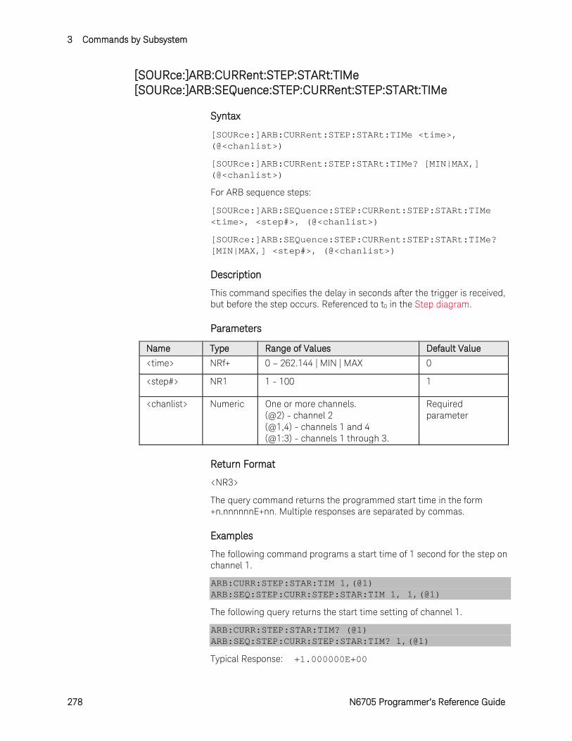
3 Commands by Subsystem
278 N6705 Programmer’s Reference Guide
[SOURce:]ARB:CURRent:STEP:STARt:TIMe [SOURce:]ARB:SEQuence:STEP:CURRent:STEP:STARt:TIMe
Syntax
[SOURce:]ARB:CURRent:STEP:STARt:TIMe <time>, (@<chanlist>)
[SOURce:]ARB:CURRent:STEP:STARt:TIMe? [MIN|MAX,] (@<chanlist>)
For ARB sequence steps:
[SOURce:]ARB:SEQuence:STEP:CURRent:STEP:STARt:TIMe <time>, <step#>, (@<chanlist>)
[SOURce:]ARB:SEQuence:STEP:CURRent:STEP:STARt:TIMe? [MIN|MAX,] <step#>, (@<chanlist>)
Description
This command specifies the delay in seconds after the trigger is received, but before the step occurs. Referenced to t0 in the Step diagram.
Parameters
Name Type Range of Values Default Value
<time> NRf+ 0 – 262.144 | MIN | MAX 0
<step#> NR1 1 - 100 1
<chanlist> Numeric One or more channels. (@2) - channel 2 (@1,4) - channels 1 and 4 (@1:3) - channels 1 through 3.
Required parameter
Return Format
<NR3>
The query command returns the programmed start time in the form +n.nnnnnnE+nn. Multiple responses are separated by commas.
Examples
The following command programs a start time of 1 second for the step on channel 1.
ARB:CURR:STEP:STAR:TIM 1,(@1) ARB:SEQ:STEP:CURR:STEP:STAR:TIM 1, 1,(@1)
The following query returns the start time setting of channel 1.
ARB:CURR:STEP:STAR:TIM? (@1) ARB:SEQ:STEP:CURR:STEP:STAR:TIM? 1,(@1)
Typical Response: +1.000000E+00

Commands by Subsystem 3
N6705 Programmer’s Reference Guide 279
See Also
[SOURce:]ARB:CURRent:STEP:STARt[:LEVel]
[SOURce:]ARB:CURRent:STEP:END[:LEVel]

3 Commands by Subsystem
280 N6705 Programmer’s Reference Guide
[SOURce:]ARB:CURRent:TRAPezoid:END:TIMe [SOURce:]ARB:SEQuence:STEP:CURRent:TRAPezoid:END:TIMe
Syntax
[SOURce:]ARB:CURRent:TRAPezoid:END:TIMe <time>, (@<chanlist>)
[SOURce:]ARB:CURRent:TRAPezoid:END:TIMe? [MIN|MAX,] (@<chanlist>)
For ARB sequence steps:
[SOURce:]ARB:SEQuence:STEP:CURRent:TRAPezoid:END :TIMe <time>, <step#>, (@<chanlist>)
[SOURce:]ARB:SEQuence:STEP:CURRent:TRAPezoid:END :TIMe? [MIN|MAX,] <step#>, (@<chanlist>)
Description
This command specifies the time in seconds, after the trapezoid completes, that the start-level current persists. Referenced to t4 in the Trapezoid diagram.
Parameters
Name Type Range of Values Default Value
<time> NRf+ 0 – 262.144 | MIN | MAX 0
<step#> NR1 1 - 100 1
<chanlist> Numeric One or more channels. (@2) - channel 2 (@1,4) - channels 1 and 4 (@1:3) - channels 1 through 3.
Required parameter
Return Format
<NR3>
The query command returns the programmed end time in the form +n.nnnnnnE+nn. Multiple responses are separated by commas.
Examples
The following command programs an end time of 1 second after the trapezoid on channel 1.
ARB:CURR:TRAP:END:TIM 1,(@1) ARB:SEQ:STEP:CURR:TRAP:END:TIM 1, 1,(@1)
The following query returns the end time setting of channel 1.
ARB:CURR:TRAP:END:TIM? (@1) ARB:SEQ:STEP:CURR:TRAP:END:TIM? 1,(@1)

Commands by Subsystem 3
N6705 Programmer’s Reference Guide 281
Typical Response: +1.000000E+00
See Also
[SOURce:]ARB:CURRent:TRAPezoid:STARt:TIMe
[SOURce:]ARB:CURRent:TRAPezoid:STARt[:LEVel]
[SOURce:]ARB:CURRent:TRAPezoid:TOP:TIMe

3 Commands by Subsystem
282 N6705 Programmer’s Reference Guide
[SOURce:]ARB:CURRent:TRAPezoid:FTIMe [SOURce:]ARB:SEQuence:STEP:CURRent:TRAPezoid:FTIMe
Syntax
[SOURce:]ARB:CURRent:TRAPezoid:FTIMe <time>, (@<chanlist>)
[SOURce:]ARB:CURRent:TRAPezoid:FTIMe? [MIN|MAX,] (@<chanlist>)
For ARB sequence steps:
[SOURce:]ARB:SEQuence:STEP:CURRent:TRAPezoid:FTIMe <time>, <step#>, (@<chanlist>)
[SOURce:]ARB:SEQuence:STEP:CURRent:TRAPezoid:FTIMe? [MIN|MAX,] <step#>, (@<chanlist>)
Description
This command specifies the fall time of the trapezoid in seconds. Referenced to t3 in the Trapezoid diagram.
Parameters
Name Type Range of Values Default Value
<time> NRf+ 0 – 262.144 | MIN | MAX 1
<step#> NR1 1 - 100 1
<chanlist> Numeric One or more channels. (@2) - channel 2 (@1,4) - channels 1 and 4 (@1:3) - channels 1 through 3.
Required parameter
Return Format
<NR3>
The query command returns the programmed fall time in the form +n.nnnnnnE+nn. Multiple responses are separated by commas.
Examples
The following command programs a fall time of 10 seconds for the trapezoid on channel 1.
ARB:CURR:TRAP:FTIM 10,(@1) ARB:SEQ:STEP:CURR:TRAP:FTIM 10, 1,(@1)
The following query returns the fall time setting of channel 1.
ARB:CURR:TRAP:FTIM? (@1) ARB:SEQ:STEP:CURR:TRAP:FTIM? 1,(@1)
Typical Response: +1.000000E+01

Commands by Subsystem 3
N6705 Programmer’s Reference Guide 283
See Also
[SOURce:]ARB:CURRent:TRAPezoid:STARt:TIMe
[SOURce:]ARB:CURRent:TRAPezoid:END:TIMe
[SOURce:]ARB:CURRent:TRAPezoid:TOP:TIMe
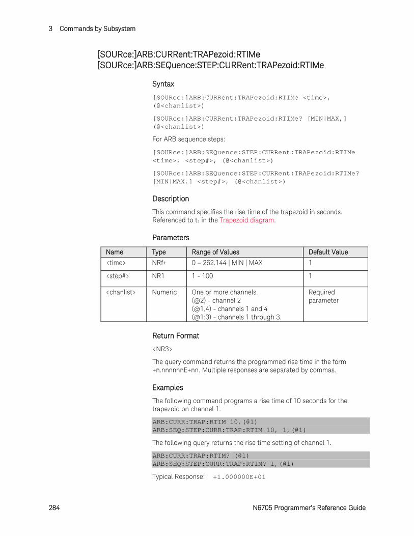
3 Commands by Subsystem
284 N6705 Programmer’s Reference Guide
[SOURce:]ARB:CURRent:TRAPezoid:RTIMe [SOURce:]ARB:SEQuence:STEP:CURRent:TRAPezoid:RTIMe
Syntax
[SOURce:]ARB:CURRent:TRAPezoid:RTIMe <time>, (@<chanlist>)
[SOURce:]ARB:CURRent:TRAPezoid:RTIMe? [MIN|MAX,] (@<chanlist>)
For ARB sequence steps:
[SOURce:]ARB:SEQuence:STEP:CURRent:TRAPezoid:RTIMe <time>, <step#>, (@<chanlist>)
[SOURce:]ARB:SEQuence:STEP:CURRent:TRAPezoid:RTIMe? [MIN|MAX,] <step#>, (@<chanlist>)
Description
This command specifies the rise time of the trapezoid in seconds. Referenced to t1 in the Trapezoid diagram.
Parameters
Name Type Range of Values Default Value
<time> NRf+ 0 – 262.144 | MIN | MAX 1
<step#> NR1 1 - 100 1
<chanlist> Numeric One or more channels. (@2) - channel 2 (@1,4) - channels 1 and 4 (@1:3) - channels 1 through 3.
Required parameter
Return Format
<NR3>
The query command returns the programmed rise time in the form +n.nnnnnnE+nn. Multiple responses are separated by commas.
Examples
The following command programs a rise time of 10 seconds for the trapezoid on channel 1.
ARB:CURR:TRAP:RTIM 10,(@1) ARB:SEQ:STEP:CURR:TRAP:RTIM 10, 1,(@1)
The following query returns the rise time setting of channel 1.
ARB:CURR:TRAP:RTIM? (@1) ARB:SEQ:STEP:CURR:TRAP:RTIM? 1,(@1)
Typical Response: +1.000000E+01
Commands by Subsystem 3
N6705 Programmer’s Reference Guide 285
See Also
[SOURce:]ARB:CURRent:TRAPezoid:STARt:TIMe
[SOURce:]ARB:CURRent:TRAPezoid:END:TIMe
[SOURce:]ARB:CURRent:TRAPezoid:TOP:TIMe

3 Commands by Subsystem
286 N6705 Programmer’s Reference Guide
[SOURce:]ARB:CURRent:TRAPeziod:STARt[:LEVel] [SOURce:]ARB:SEQuence:STEP:CURRent:TRAPezoid:STARt[:LEVel]
Syntax
[SOURce:]ARB:CURRent:TRAPeziod:STARt[:LEVel] <current>, (@<chanlist>)
[SOURce:]ARB:CURRent:TRAPeziod:STARt[:LEVel]? [MIN|MAX,] (@<chanlist>)
For ARB sequence steps:
[SOURce:]ARB:SEQuence:STEP:CURRent:TRAPezoid:STARt[:LEVel] <current>, <step#>, (@<chanlist>)
[SOURce:]ARB:SEQuence:STEP:CURRent:TRAPezoid:STARt[:LEVel]? [MIN|MAX,] <step#>, (@<chanlist>)
Description
This command specifies the initial and final current level of the trapezoid in amperes. Referenced to I0 in the Trapezoid diagram.
Parameters
Name Type Range of Values Default Value
<current> NRf+ 0 - maximum | MIN | MAX The maximum value is dependent on the current rating of the power module.
MIN
<step#> NR1 1 - 100 1
<chanlist> Numeric One or more channels. (@2) - channel 2 (@1,4) - channels 1 and 4 (@1:3) - channels 1 through 3.
Required parameter
Return Format
<NR3>
The query command returns the programmed current level in the form +n.nnnnnnE+nn. Multiple responses are separated by commas.
Examples
The following command programs the initial and final current for the trapezoid on channel 1.
ARB:CURR:TRAP:STAR 1,(@1) ARB:SEQ:STEP:CURR:TRAP:STAR 1, 1,(@1)
The following query returns the starting and ending current setting of channel 1.

Commands by Subsystem 3
N6705 Programmer’s Reference Guide 287
ARB:CURR:TRAP:STAR? (@1) ARB:SEQ:STEP:CURR:TRAP:STAR? 1,(@1)
Typical Response: +1.000000E+00
See Also
[SOURce:]ARB:CURRent:TRAPezoid:STARt:TIMe
[SOURce:]ARB:CURRent:TRAPezoid:TOP[:LEVel]
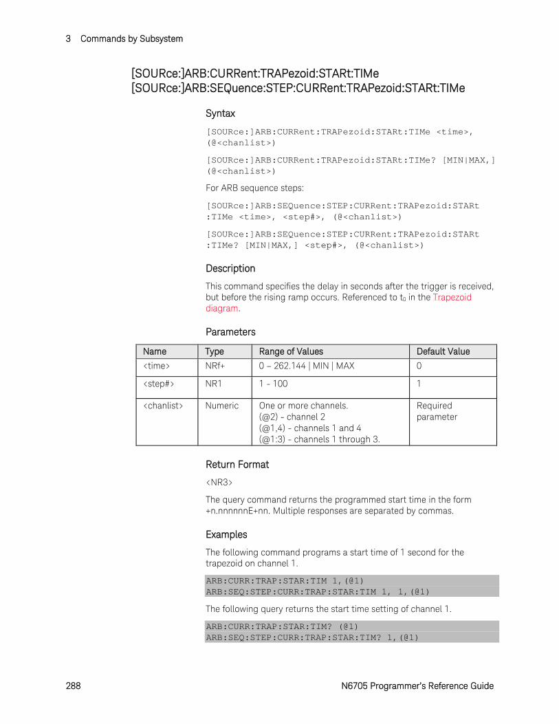
3 Commands by Subsystem
288 N6705 Programmer’s Reference Guide
[SOURce:]ARB:CURRent:TRAPezoid:STARt:TIMe [SOURce:]ARB:SEQuence:STEP:CURRent:TRAPezoid:STARt:TIMe
Syntax
[SOURce:]ARB:CURRent:TRAPezoid:STARt:TIMe <time>, (@<chanlist>)
[SOURce:]ARB:CURRent:TRAPezoid:STARt:TIMe? [MIN|MAX,] (@<chanlist>)
For ARB sequence steps:
[SOURce:]ARB:SEQuence:STEP:CURRent:TRAPezoid:STARt :TIMe <time>, <step#>, (@<chanlist>)
[SOURce:]ARB:SEQuence:STEP:CURRent:TRAPezoid:STARt :TIMe? [MIN|MAX,] <step#>, (@<chanlist>)
Description
This command specifies the delay in seconds after the trigger is received, but before the rising ramp occurs. Referenced to t0 in the Trapezoid diagram.
Parameters
Name Type Range of Values Default Value
<time> NRf+ 0 – 262.144 | MIN | MAX 0
<step#> NR1 1 - 100 1
<chanlist> Numeric One or more channels. (@2) - channel 2 (@1,4) - channels 1 and 4 (@1:3) - channels 1 through 3.
Required parameter
Return Format
<NR3>
The query command returns the programmed start time in the form +n.nnnnnnE+nn. Multiple responses are separated by commas.
Examples
The following command programs a start time of 1 second for the trapezoid on channel 1.
ARB:CURR:TRAP:STAR:TIM 1,(@1) ARB:SEQ:STEP:CURR:TRAP:STAR:TIM 1, 1,(@1)
The following query returns the start time setting of channel 1.
ARB:CURR:TRAP:STAR:TIM? (@1) ARB:SEQ:STEP:CURR:TRAP:STAR:TIM? 1,(@1)
Commands by Subsystem 3
N6705 Programmer’s Reference Guide 289
Typical Response: +1.000000E+00
See Also
[SOURce:]ARB:CURRent:TRAPezoid:STARt[:LEVel]
[SOURce:]ARB:CURRent:TRAPezoid:END:TIMe
[SOURce:]ARB:CURRent:TRAPezoid:TOP:TIMe

3 Commands by Subsystem
290 N6705 Programmer’s Reference Guide
[SOURce:]ARB:CURRent:TRAPezoid:TOP[:LEVel] [SOURce:]ARB:SEQuence:STEP:CURRent:TRAPezoid:TOP[:LEVel]
Syntax
[SOURce:]ARB:CURRent:TRAPezoid:TOP[:LEVel] <current>, (@<chanlist>)
[SOURce:]ARB:CURRent:TRAPezoid:TOP[:LEVel]? [MIN|MAX,] (@<chanlist>)
For ARB sequence steps:
[SOURce:]ARB:SEQuence:STEP:CURRent:TRAPezoid:TOP [:LEVel] <current>, <step#>, (@<chanlist>)
[SOURce:]ARB:SEQuence:STEP:CURRent:TRAPezoid:TOP [:LEVel]? [MIN|MAX,] <step#>, (@<chanlist>)
Description
This command specifies the top level current of the trapezoid in amperes. Referenced to I1 in the Trapezoid diagram.
Parameters
Name Type Range of Values Default Value
<current> NRf+ 0 - maximum | MIN | MAX The maximum value is dependent on the current rating of the power module.
MIN
<step#> NR1 1 - 100 1
<chanlist> Numeric One or more channels. (@2) - channel 2 (@1,4) - channels 1 and 4 (@1:3) - channels 1 through 3.
Required parameter
Return Format
<NR3>
The query command returns the programmed current level in the form +n.nnnnnnE+nn. Multiple responses are separated by commas.
Examples
The following command programs a top level current for the trapezoid on channel 1.
ARB:CURR:TRAP:TOP 2,(@1) ARB:SEQ:STEP:CURR:TRAP:TOP 2, 1,(@1)
The following query returns the top level current setting of channel 1.

Commands by Subsystem 3
N6705 Programmer’s Reference Guide 291
ARB:CURR:TRAP:TOP? (@1) ARB:SEQ:STEP:CURR:TRAP:TOP? 1,(@1)
Typical Response: +2.000000E+00
See Also
[SOURce:]ARB:CURRent:TRAPezoid:STARt[:LEVel]
[SOURce:]ARB:CURRent:TRAPezoid:TOP:TIMe
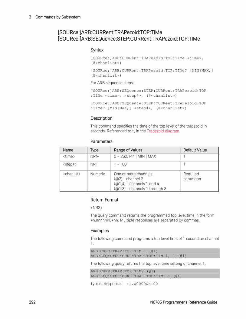
3 Commands by Subsystem
292 N6705 Programmer’s Reference Guide
[SOURce:]ARB:CURRent:TRAPezoid:TOP:TIMe [SOURce:]ARB:SEQuence:STEP:CURRent:TRAPezoid:TOP:TIMe
Syntax
[SOURce:]ARB:CURRent:TRAPezoid:TOP:TIMe <time>, (@<chanlist>)
[SOURce:]ARB:CURRent:TRAPezoid:TOP:TIMe? [MIN|MAX,] (@<chanlist>)
For ARB sequence steps:
[SOURce:]ARB:SEQuence:STEP:CURRent:TRAPezoid:TOP :TIMe <time>, <step#>, (@<chanlist>)
[SOURce:]ARB:SEQuence:STEP:CURRent:TRAPezoid:TOP :TIMe? [MIN|MAX,] <step#>, (@<chanlist>)
Description
This command specifies the time of the top level of the trapezoid in seconds. Referenced to t2 in the Trapezoid diagram.
Parameters
Name Type Range of Values Default Value
<time> NRf+ 0 – 262.144 | MIN | MAX 1
<step#> NR1 1 - 100 1
<chanlist> Numeric One or more channels. (@2) - channel 2 (@1,4) - channels 1 and 4 (@1:3) - channels 1 through 3.
Required parameter
Return Format
<NR3>
The query command returns the programmed top level time in the form +n.nnnnnnE+nn. Multiple responses are separated by commas.
Examples
The following command programs a top level time of 1 second on channel 1.
ARB:CURR:TRAP:TOP:TIM 1,(@1) ARB:SEQ:STEP:CURR:TRAP:TOP:TIM 1, 1,(@1)
The following query returns the top level time setting of channel 1.
ARB:CURR:TRAP:TOP:TIM? (@1) ARB:SEQ:STEP:CURR:TRAP:TOP:TIM? 1,(@1)
Typical Response: +1.000000E+00

Commands by Subsystem 3
N6705 Programmer’s Reference Guide 293
See Also
[SOURce:]ARB:CURRent:TRAPezoid:RTIMe
[SOURce:]ARB:CURRent:TRAPezoid:FTIMe
3 Commands by Subsystem
294 N6705 Programmer’s Reference Guide
[SOURce:]ARB:CURRent:UDEFined:BOSTep[:DATA] [SOURce:]ARB:SEQuence:STEP:CURRent:UDEFined:BOSTep[:DATA]
Syntax
[SOURce:]ARB:CURRent:UDEFined:BOSTep[:DATA] <Bool>,<Bool>, (@<chanlist>)
[SOURce:]ARB:CURRent:UDEFined:BOSTep[:DATA]? (@<chanlist>)
For ARB sequence steps:
[SOURce:]ARB:SEQuence:STEP:CURRent:UDEFined:BOSTep [:DATA] <Bool>,<Bool>, <step#>, (@<chanlist>)
[SOURce:]ARB:SEQuence:STEP:CURRent:UDEFined:BOSTep [:DATA]? <step#>, (@<chanlist>)
Description
This command specifies which user-defined ARB points or steps will generate a trigger-out signal at the beginning of the step (BOSTep). A comma-delimited list of up to 511 steps may be programmed. The state is either ON (1) or OFF (0).
A trigger is only generated when the state is set to ON.
Parameters
Name Type Range of Values Default Value
<Bool> Boolean OFF | 0 | ON | 1 1 point with a value of OFF
<step#> NR1 1 - 100 1
<chanlist> Numeric One or more channels. (@2) - channel 2 (@1,4) - channels 1 and 4 (@1:3) - channels 1 through 3.
Required parameter
Return Format
<NR1>
The query command returns 0 if no trigger is generated, and 1 if a trigger is generated. Multiple responses are separated by commas.
Examples
The following command specifies that triggers will be generated at the beginning of each user-defined ARB step. The ARB contains 5 points or steps and is on channel 1.
ARB:CURR:UDEF:BOST ON,ON,ON,ON,ON,(@1) ARB:SEQ:STEP:CURR:UDEF:BOST ON,ON,ON,ON,ON,1,(@1)
Commands by Subsystem 3
N6705 Programmer’s Reference Guide 295
The following query returns the ARB step trigger settings of channel 1.
ARB:CURR:UDEF:BOST? (@1) ARB:SEQ:STEP:CURR:UDEF:BOST? 1,(@1)
Typical Response: 1,1,1,1,1

3 Commands by Subsystem
296 N6705 Programmer’s Reference Guide
[SOURce:]ARB:CURRent:UDEFined:BOSTep:POINts? [SOURce:]ARB:SEQuence:STEP:CURRent:UDEFined:BOSTep:POINts?
Syntax
[SOURce:]ARB:CURRent:UDEFined:BOSTep:POINts? (@<chanlist>)
For ARB sequence steps:
[SOURce:]ARB:SEQuence:STEP:CURRent:UDEFined:BOSTep :POINts? <step#>, (@<chanlist>)
Description
This query returns the number of beginning-of-step points in the user-defined ARB, not the point values.
Parameters
Name Type Range of Values Default Value
<step#> NR1 1 - 100 1
<chanlist> Numeric One or more channels. (@2) - channel 2 (@1,4) - channels 1 and 4 (@1:3) - channels 1 through 3.
Required parameter
Return Format
<NR1>
The number of BOST points in the user-defined ARB. Multiple responses are separated by commas.
Example
The following query returns the number of BOST points in a user-defined ARB for channel 1.
ARB:CURR:UDEF:BOST:POIN? (@1) ARB:SEQ:STEP:CURR:UDEF:BOST:POIN? 1,(@1)
Typical Response: +1
Commands by Subsystem 3
N6705 Programmer’s Reference Guide 297
[SOURce:]ARB:CURRent:UDEFined:DWELl [SOURce:]ARB:SEQuence:STEP:CURRent:UDEFined:DWELl
Syntax
[SOURce:]ARB:CURRent:UDEFined:DWELl <time>,<time>, (@<chanlist>)
[SOURce:]ARB:CURRent:UDEFined:DWELl? (@<chanlist>)
For ARB sequence steps:
[SOURce:]ARB:SEQuence:STEP:CURRent:UDEFined:DWELl <time>,<time>, <step#>, (@<chanlist>)
[SOURce:]ARB:SEQuence:STEP:CURRent:UDEFined:DWELl? <step#>, (@<chanlist>)
Description
This command specifies the dwell time for each user-defined current ARB point. A comma-delimited list of up to 511 points may be programmed. Dwell time is the time that the output will remain at a specific point. Dwell times can be programmed from 0 through 262.144 seconds with the following resolution:
All Models except N678xA Range in seconds Resolution 0 - 0.262144 1 microsecond 0 - 2.62144 10 microseconds 0 - 26.2144 100 microseconds 0 - 262.144 1 millisecond Models N678xA only Range in seconds Resolution 0 - 0.268435 1.024 microsecond 0 - 2.68435 10.24 microseconds 0 - 26.8435 102.4 microseconds 0 - 268.435 1.024 millisecond
Parameters
Name Type Range of Values Default Value
<time> NRf 0 - 262.144 (all except N678xA SMU) 0 - 268.435 (N678xA SMU only)
1 point with a value of 0.001
<step#> NR1 1 - 100 1
<chanlist> Numeric One or more channels. (@2) - channel 2 (@1,4) - channels 1 and 4 (@1:3) - channels 1 through 3.
Required parameter
3 Commands by Subsystem
298 N6705 Programmer’s Reference Guide
Remarks
At the end of the dwell time, the output state of the unit depends upon the [SOURce;]ARB:TERMinate:LAST program settings.
The order in which the dwell values are entered determines the sequence of execution.
To create a valid user-defined ARB, the Current level, BOST, and Dwell lists must either all be the same length, or have a length of 1, which is interpolated as having the same length as the maximum length list.
Return Format
<NR3>
The query command returns the programmed dwell time in the form +n.nnnnnnE+nn. Multiple responses are separated by commas.
Examples
The following command programs a dwell list. The list contains 5 steps and is on channel 1.
ARB:CURR:UDEF:DWEL 0.2,0.8,1.5,0.8,0.2,(@1) ARB:SEQ:STEP:CURR:UDEF:DWEL 0.2,0.8,1.5,0.8,0.2,1,(@1)
The following query returns the dwell list settings of channel 1.
ARB:CURR:UDEF:DWEL? (@1) ARB:SEQ:STEP:CURR:UDEF:DWEL? 1,(@1)
Typical Response: +2.000000E-01,+8.000000E-01,+1.500000E+00,+8.000000E-01,+02.000000E-01
See Also
[SOURce:]ARB:CURRent:UDEFined:LEVel
[SOURce:]ARB:CURRent:UDEFined:BOST
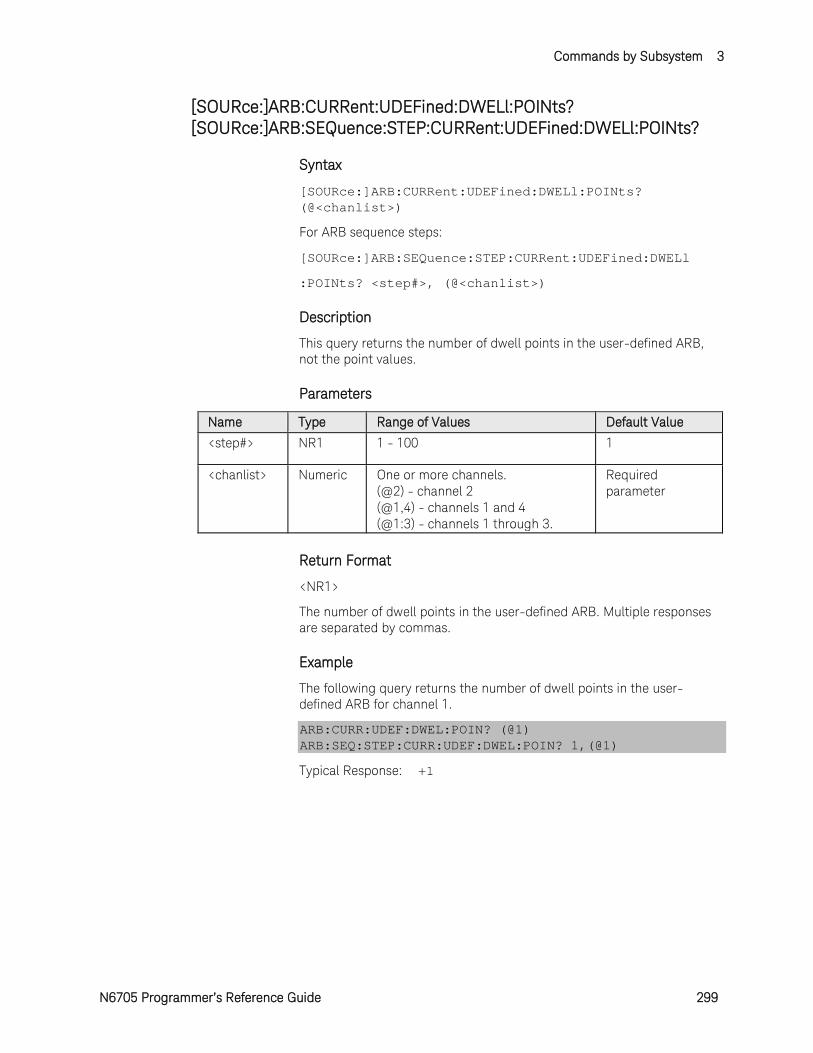
Commands by Subsystem 3
N6705 Programmer’s Reference Guide 299
[SOURce:]ARB:CURRent:UDEFined:DWELl:POINts? [SOURce:]ARB:SEQuence:STEP:CURRent:UDEFined:DWELl:POINts?
Syntax
[SOURce:]ARB:CURRent:UDEFined:DWELl:POINts? (@<chanlist>)
For ARB sequence steps:
[SOURce:]ARB:SEQuence:STEP:CURRent:UDEFined:DWELl
:POINts? <step#>, (@<chanlist>)
Description
This query returns the number of dwell points in the user-defined ARB, not the point values.
Parameters
Name Type Range of Values Default Value
<step#> NR1 1 - 100 1
<chanlist> Numeric One or more channels. (@2) - channel 2 (@1,4) - channels 1 and 4 (@1:3) - channels 1 through 3.
Required parameter
Return Format
<NR1>
The number of dwell points in the user-defined ARB. Multiple responses are separated by commas.
Example
The following query returns the number of dwell points in the user-defined ARB for channel 1.
ARB:CURR:UDEF:DWEL:POIN? (@1) ARB:SEQ:STEP:CURR:UDEF:DWEL:POIN? 1,(@1)
Typical Response: +1
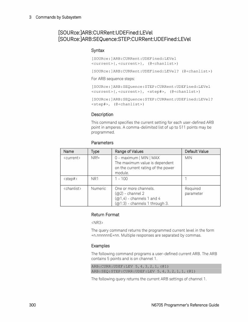
3 Commands by Subsystem
300 N6705 Programmer’s Reference Guide
[SOURce:]ARB:CURRent:UDEFined:LEVel [SOURce:]ARB:SEQuence:STEP:CURRent:UDEFined:LEVel
Syntax
[SOURce:]ARB:CURRent:UDEFined:LEVel <current>,<current>, (@<chanlist>)
[SOURce:]ARB:CURRent:UDEFined:LEVel? (@<chanlist>)
For ARB sequence steps:
[SOURce:]ARB:SEQuence:STEP:CURRent:UDEFined:LEVel <current>,<current>, <step#>, (@<chanlist>)
[SOURce:]ARB:SEQuence:STEP:CURRent:UDEFined:LEVel? <step#>, (@<chanlist>)
Description
This command specifies the current setting for each user-defined ARB point in amperes. A comma-delimited list of up to 511 points may be programmed.
Parameters
Name Type Range of Values Default Value
<current> NRf+ 0 - maximum | MIN | MAX The maximum value is dependent on the current rating of the power module.
MIN
<step#> NR1 1 - 100 1
<chanlist> Numeric One or more channels. (@2) - channel 2 (@1,4) - channels 1 and 4 (@1:3) - channels 1 through 3.
Required parameter
Return Format
<NR3>
The query command returns the programmed current level in the form +n.nnnnnnE+nn. Multiple responses are separated by commas.
Examples
The following command programs a user-defined current ARB. The ARB contains 5 points and is on channel 1.
ARB:CURR:UDEF:LEV 5,4,3,2,1,(@1) ARB:SEQ:STEP:CURR:UDEF:LEV 5,4,3,2,1,1,(@1)
The following query returns the current ARB settings of channel 1.
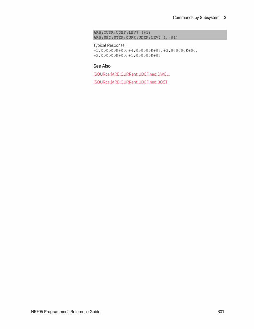
Commands by Subsystem 3
N6705 Programmer’s Reference Guide 301
ARB:CURR:UDEF:LEV? (@1) ARB:SEQ:STEP:CURR:UDEF:LEV? 1,(@1)
Typical Response: +5.000000E+00,+4.000000E+00,+3.000000E+00, +2.000000E+00,+1.000000E+00
See Also
[SOURce:]ARB:CURRent:UDEFined:DWELl
[SOURce:]ARB:CURRent:UDEFined:BOST
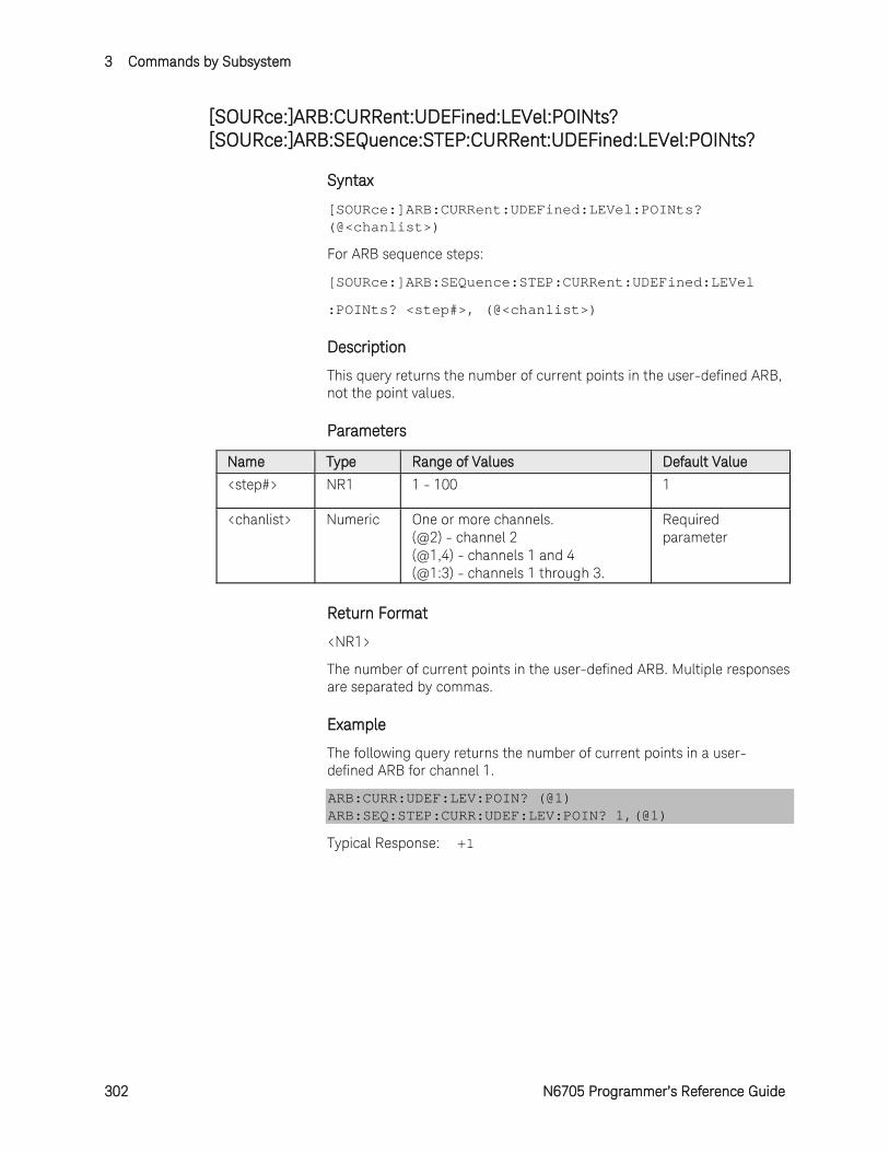
3 Commands by Subsystem
302 N6705 Programmer’s Reference Guide
[SOURce:]ARB:CURRent:UDEFined:LEVel:POINts? [SOURce:]ARB:SEQuence:STEP:CURRent:UDEFined:LEVel:POINts?
Syntax
[SOURce:]ARB:CURRent:UDEFined:LEVel:POINts? (@<chanlist>)
For ARB sequence steps:
[SOURce:]ARB:SEQuence:STEP:CURRent:UDEFined:LEVel
:POINts? <step#>, (@<chanlist>)
Description
This query returns the number of current points in the user-defined ARB, not the point values.
Parameters
Name Type Range of Values Default Value
<step#> NR1 1 - 100 1
<chanlist> Numeric One or more channels. (@2) - channel 2 (@1,4) - channels 1 and 4 (@1:3) - channels 1 through 3.
Required parameter
Return Format
<NR1>
The number of current points in the user-defined ARB. Multiple responses are separated by commas.
Example
The following query returns the number of current points in a user-defined ARB for channel 1.
ARB:CURR:UDEF:LEV:POIN? (@1) ARB:SEQ:STEP:CURR:UDEF:LEV:POIN? 1,(@1)
Typical Response: +1
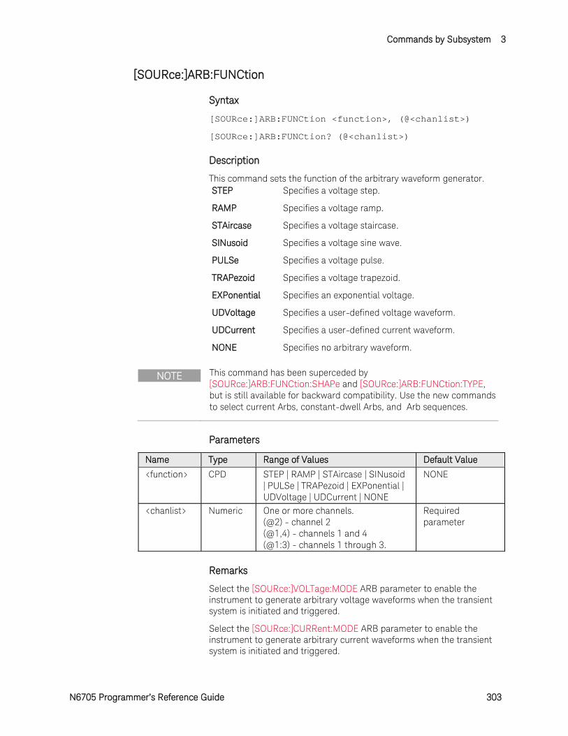
Commands by Subsystem 3
N6705 Programmer’s Reference Guide 303
[SOURce:]ARB:FUNCtion
Syntax
[SOURce:]ARB:FUNCtion <function>, (@<chanlist>)
[SOURce:]ARB:FUNCtion? (@<chanlist>)
Description
This command sets the function of the arbitrary waveform generator. STEP Specifies a voltage step.
RAMP Specifies a voltage ramp.
STAircase Specifies a voltage staircase.
SINusoid Specifies a voltage sine wave.
PULSe Specifies a voltage pulse.
TRAPezoid Specifies a voltage trapezoid.
EXPonential Specifies an exponential voltage.
UDVoltage Specifies a user-defined voltage waveform.
UDCurrent Specifies a user-defined current waveform.
NONE Specifies no arbitrary waveform.
NOTE This command has been superceded by [SOURce:]ARB:FUNCtion:SHAPe and [SOURce:]ARB:FUNCtion:TYPE, but is still available for backward compatibility. Use the new commands to select current Arbs, constant-dwell Arbs, and Arb sequences.
Parameters
Name Type Range of Values Default Value
<function> CPD STEP | RAMP | STAircase | SINusoid | PULSe | TRAPezoid | EXPonential | UDVoltage | UDCurrent | NONE
NONE
<chanlist> Numeric One or more channels. (@2) - channel 2 (@1,4) - channels 1 and 4 (@1:3) - channels 1 through 3.
Required parameter
Remarks
Select the [SOURce:]VOLTage:MODE ARB parameter to enable the instrument to generate arbitrary voltage waveforms when the transient system is initiated and triggered.
Select the [SOURce:]CURRent:MODE ARB parameter to enable the instrument to generate arbitrary current waveforms when the transient system is initiated and triggered.
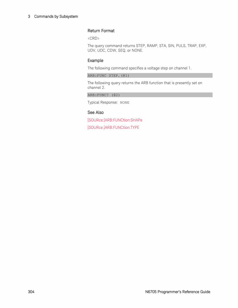
3 Commands by Subsystem
304 N6705 Programmer’s Reference Guide
Return Format
<CRD>
The query command returns STEP, RAMP, STA, SIN, PULS, TRAP, EXP, UDV, UDC, CDW, SEQ, or NONE.
Example
The following command specifies a voltage step on channel 1.
ARB:FUNC STEP,(@1)
The following query returns the ARB function that is presently set on channel 2.
ARB:FUNC? (@2)
Typical Response: NONE
See Also
[SOURce:]ARB:FUNCtion:SHAPe
[SOURce:]ARB:FUNCtion:TYPE
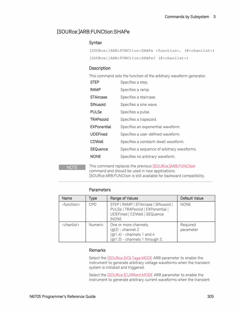
Commands by Subsystem 3
N6705 Programmer’s Reference Guide 305
[SOURce:]ARB:FUNCtion:SHAPe
Syntax
[SOURce:]ARB:FUNCtion:SHAPe <function>, (@<chanlist>)
[SOURce:]ARB:FUNCtion:SHAPe? (@<chanlist>)
Description
This command sets the function of the arbitrary waveform generator.
STEP Specifies a step.
RAMP Specifies a ramp.
STAircase Specifies a staircase.
SINusoid Specifies a sine wave.
PULSe Specifies a pulse.
TRAPezoid Specifies a trapezoid.
EXPonential Specifies an exponential waveform.
UDEFined Specifies a user-defined waveform.
CDWell Specifies a constant-dwell waveform.
SEQuence Specifies a sequence of arbitrary waveforms.
NONE Specifies no arbitrary waveform.
NOTE This command replaces the previous [SOURce:]ARB:FUNCtion command and should be used in new applications. [SOURce:ARB:FUNCtion is still available for backward compatibility.
Parameters
Name Type Range of Values Default Value
<function> CPD STEP | RAMP | STAircase | SINusoid | PULSe | TRAPezoid | EXPonential | UDEFined | CDWell | SEQuence |NONE
NONE
<chanlist> Numeric One or more channels. (@2) - channel 2 (@1,4) - channels 1 and 4 (@1:3) - channels 1 through 3.
Required parameter
Remarks
Select the [SOURce:]VOLTage:MODE ARB parameter to enable the instrument to generate arbitrary voltage waveforms when the transient system is initiated and triggered.
Select the [SOURce:]CURRent:MODE ARB parameter to enable the instrument to generate arbitrary current waveforms when the transient
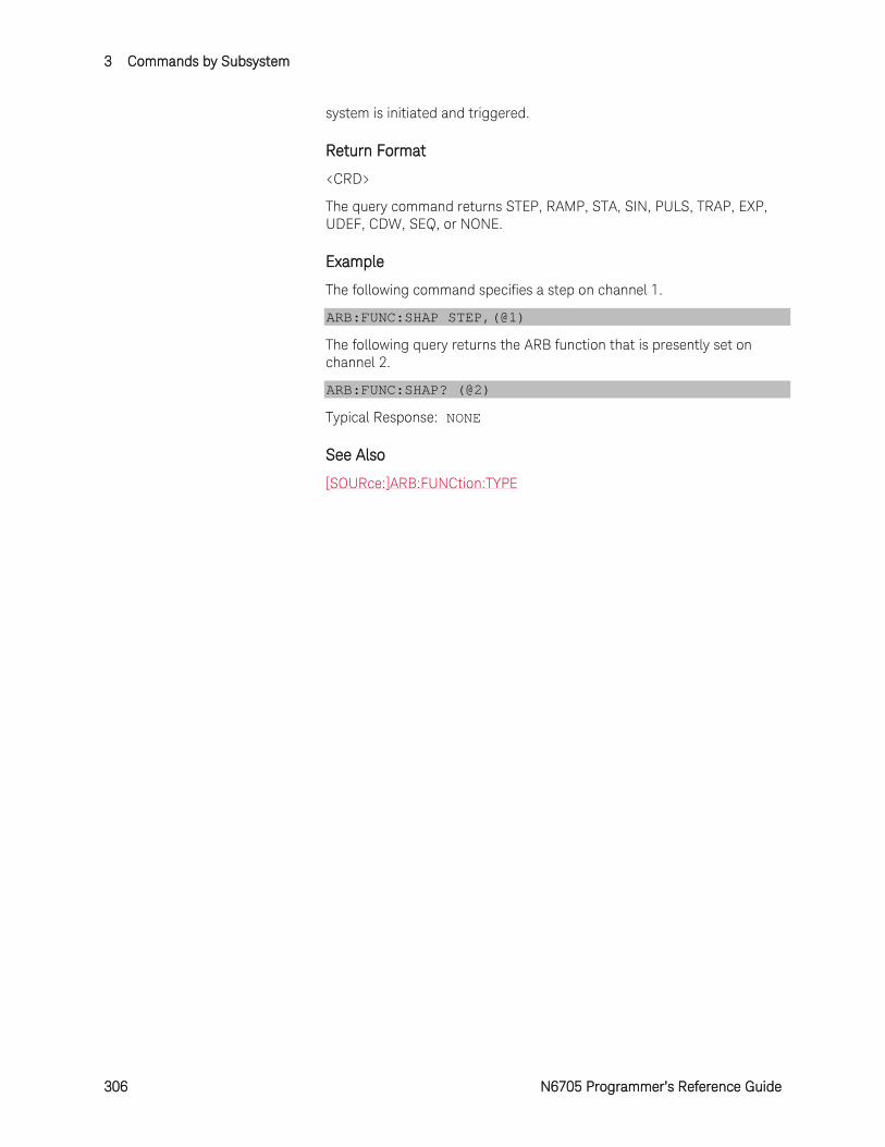
3 Commands by Subsystem
306 N6705 Programmer’s Reference Guide
system is initiated and triggered.
Return Format
<CRD>
The query command returns STEP, RAMP, STA, SIN, PULS, TRAP, EXP, UDEF, CDW, SEQ, or NONE.
Example
The following command specifies a step on channel 1.
ARB:FUNC:SHAP STEP,(@1)
The following query returns the ARB function that is presently set on channel 2.
ARB:FUNC:SHAP? (@2)
Typical Response: NONE
See Also
[SOURce:]ARB:FUNCtion:TYPE
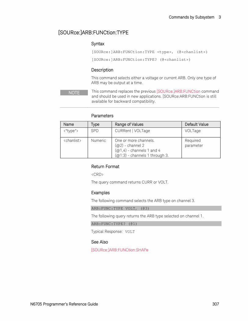
Commands by Subsystem 3
N6705 Programmer’s Reference Guide 307
[SOURce:]ARB:FUNCtion:TYPE
Syntax
[SOURce:]ARB:FUNCtion:TYPE <type>, (@<chanlist>)
[SOURce:]ARB:FUNCtion:TYPE? (@<chanlist>)
Description
This command selects either a voltage or current ARB. Only one type of ARB may be output at a time.
NOTE This command replaces the previous [SOURce:]ARB:FUNCtion command and should be used in new applications. [SOURce:ARB:FUNCtion is still available for backward compatibility.
Parameters
Name Type Range of Values Default Value
<"type"> SPD CURRent | VOLTage VOLTage
<chanlist> Numeric One or more channels. (@2) - channel 2 (@1,4) - channels 1 and 4 (@1:3) - channels 1 through 3.
Required parameter
Return Format
<CRD>
The query command returns CURR or VOLT.
Examples
The following command selects the ARB type on channel 3.
ARB:FUNC:TYPE VOLT, (@3)
The following query returns the ARB type selected on channel 1.
ARB:FUNC:TYPE? (@1)
Typical Response: VOLT
See Also
[SOURce:]ARB:FUNCtion:SHAPe
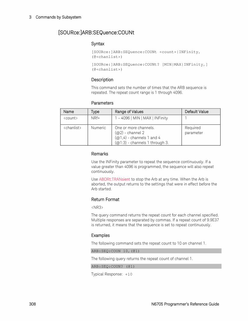
3 Commands by Subsystem
308 N6705 Programmer’s Reference Guide
[SOURce:]ARB:SEQuence:COUNt
Syntax
[SOURce:]ARB:SEQuence:COUNt <count>|INFinity, (@<chanlist>)
[SOURce:]ARB:SEQuence:COUNt? [MIN|MAX|INFinity,] (@<chanlist>)
Description
This command sets the number of times that the ARB sequence is repeated. The repeat count range is 1 through 4096.
Parameters
Name Type Range of Values Default Value
<count> NRf+ 1 - 4096 | MIN | MAX | INFinity 1
<chanlist> Numeric One or more channels. (@2) - channel 2 (@1,4) - channels 1 and 4 (@1:3) - channels 1 through 3.
Required parameter
Remarks
Use the INFinity parameter to repeat the sequence continuously. If a value greater than 4096 is programmed, the sequence will also repeat continuously.
Use ABORt:TRANsient to stop the Arb at any time. When the Arb is aborted, the output returns to the settings that were in effect before the Arb started.
Return Format
<NR3>
The query command returns the repeat count for each channel specified. Multiple responses are separated by commas. If a repeat count of 9.9E37 is returned, it means that the sequence is set to repeat continuously.
Examples
The following command sets the repeat count to 10 on channel 1.
ARB:SEQ:COUN 10,(@1)
The following query returns the repeat count of channel 1.
ARB:SEQ:COUN? (@1)
Typical Response: +10
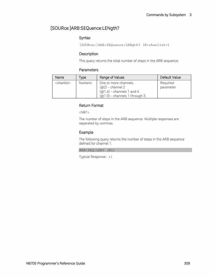
Commands by Subsystem 3
N6705 Programmer’s Reference Guide 309
[SOURce:]ARB:SEQuence:LENgth?
Syntax
[SOURce:]ARB:SEQuence:LENgth? (@<chanlist>)
Description
This query returns the total number of steps in the ARB sequence.
Parameters
Name Type Range of Values Default Value
<chanlist> Numeric One or more channels. (@2) - channel 2 (@1,4) - channels 1 and 4 (@1:3) - channels 1 through 3.
Required parameter
Return Format
<NR1>
The number of steps in the ARB sequence. Multiple responses are separated by commas.
Example
The following query returns the number of steps in the ARB sequence defined for channel 1.
ARB:SEQ:LEN? (@1)
Typical Response: +1
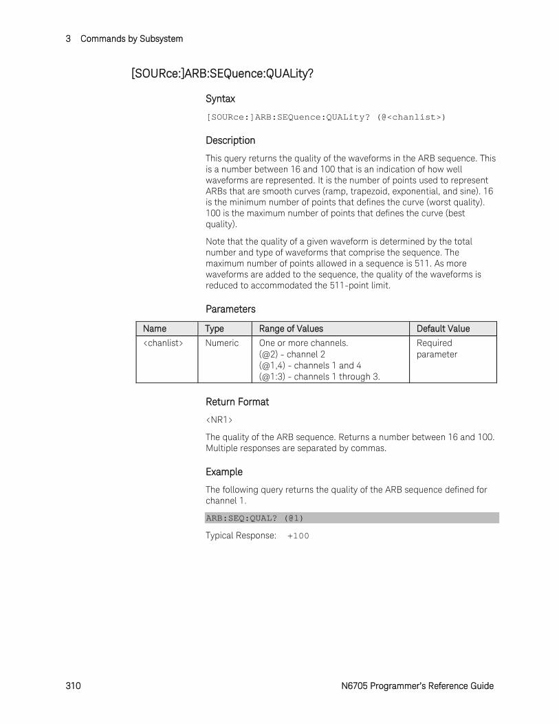
3 Commands by Subsystem
310 N6705 Programmer’s Reference Guide
[SOURce:]ARB:SEQuence:QUALity?
Syntax
[SOURce:]ARB:SEQuence:QUALity? (@<chanlist>)
Description
This query returns the quality of the waveforms in the ARB sequence. This is a number between 16 and 100 that is an indication of how well waveforms are represented. It is the number of points used to represent ARBs that are smooth curves (ramp, trapezoid, exponential, and sine). 16 is the minimum number of points that defines the curve (worst quality). 100 is the maximum number of points that defines the curve (best quality).
Note that the quality of a given waveform is determined by the total number and type of waveforms that comprise the sequence. The maximum number of points allowed in a sequence is 511. As more waveforms are added to the sequence, the quality of the waveforms is reduced to accommodated the 511-point limit.
Parameters
Name Type Range of Values Default Value
<chanlist> Numeric One or more channels. (@2) - channel 2 (@1,4) - channels 1 and 4 (@1:3) - channels 1 through 3.
Required parameter
Return Format
<NR1>
The quality of the ARB sequence. Returns a number between 16 and 100. Multiple responses are separated by commas.
Example
The following query returns the quality of the ARB sequence defined for channel 1.
ARB:SEQ:QUAL? (@1)
Typical Response: +100
Commands by Subsystem 3
N6705 Programmer’s Reference Guide 311
[SOURce:]ARB:SEQuence:RESet
Syntax
[SOURce:]ARB:SEQuence:RESet (@<chanlist>)
Description
This command resets the ARB sequence to its power-on default setting: Step = 1 Shape = PULSe
Parameters
Name Type Range of Values Default Value
<chanlist> Numeric One or more channels. (@2) - channel 2 (@1,4) - channels 1 and 4 (@1:3) - channels 1 through 3.
Required parameter
Example
The following command resets the ARB sequence on channel 1.
ARB:SEQ:RES (@1)
3 Commands by Subsystem
312 N6705 Programmer’s Reference Guide
[SOURce:]ARB:SEQuence:STEP:COUNt
Syntax
[SOURce:]ARB:SEQuence:STEP:COUNt <count>|INFinity, <step#>, (@<chanlist>)
[SOURce:]ARB:SEQuence:STEP:COUNt? [MIN|MAX|INFinity,] <step#>, (@<chanlist>)
Description
This command sets the number of times that the sequence step is repeated. The repeat count range is 1 through >16 million. The maximum number of steps that can be programmed is 100. This setting is only valid if the [SOURce:]ARB:SEQuence:STEP:PACing is TRIGgered.
Parameters
Name Type Range of Values Default Value
<count> NRf+ 1 - 16,777,216 | MIN | MAX | INFinity
1
<step#> NR1 1 - 100 1 <chanlist> Numeric One or more channels.
(@2) - channel 2 (@1,4) - channels 1 and 4 (@1:3) - channels 1 through 3.
Required parameter
Remarks
Use the INFinity parameter to repeat the sequence step continuously. If MAX, or a value greater than 16,777,216 is programmed, the step will also repeat continuously.
Use ABORt:TRANsient to stop the Arb at any time. When the Arb is aborted, the output returns to the settings that were in effect before the Arb started.
Return Format
<NR3>
The query command returns the repeat count for each channel specified. Multiple responses are separated by commas. If a repeat count of 9.9E37 is returned, it means that the sequence step is set to repeat continuously.
Examples
The following command sets the a repeat count of 10 for sequence step 1 on channel 1.
ARB:SEQ:STEP:COUN 10, 1,(@1)
The following query returns the sequence step repeat count of channel 1.
ARB:SEQ:STEP:COUN? 1,(@1)
Commands by Subsystem 3
N6705 Programmer’s Reference Guide 313
Typical Response: +10
See Also
[SOURce:]ARB:SEQuence:STEP:PACing
3 Commands by Subsystem
314 N6705 Programmer’s Reference Guide
[SOURce:]ARB:SEQuence:STEP:CURRent
The [SOURce:]ARB:SEQuence:STEP:CURRent commands program waveform steps within an ARB sequence.
All of the [SOURce:]ARB:CURRent commands that set waveform parameters have corresponding commands that set those same parameters for waveform steps within an ARB sequence. They follow the pattern:
[SOURce:]ARB:CURRent:EXPonential:END <level>, (@<chanlist>)
[SOURce:]ARB:SEQuence:STEP:CURRent:EXPonential:END <level>, <step#>, (@<chanlist>)
where items in bold are added to the sequence step version of the single ARB command. The <step#> parameter indicates the step number within the ARB sequence.
Command Summary
NOTE The following links reference the corresponding single ARB command. All parameters in the single ARB command match the ARB sequence step version of the command. The only additional parameter in the ARB sequence command is the <step#> parameter, which references the step number within the sequence.
[SOURce:]ARB:SEQuence:STEP:CURRent:EXPonential:END[:LEVel]
[SOURce:]ARB:SEQuence:STEP:CURRent:EXPonential:STARt[:LEVel]
[SOURce:]ARB:SEQuence:STEP:CURRent:EXPonential:STARt:TIMe
[SOURce:]ARB:SEQuence:STEP:CURRent:EXPonential:TCONstant
[SOURce:]ARB:SEQuence:STEP:CURRent:EXPonential:TIMe
[SOURce:]ARB:SEQuence:STEP:CURRent:PULSe:END:TIMe
[SOURce:]ARB:SEQuence:STEP:CURRent:PULSe:STARt[:LEVel]
[SOURce:]ARB:SEQuence:STEP:CURRent:PULSe:STARt:TIMe
[SOURce:]ARB:SEQuence:STEP:CURRent:PULSe:TOP[:LEVel]
[SOURce:]ARB:SEQuence:STEP:CURRent:PULSe:TOP:TIMe
[SOURce:]ARB:SEQuence:STEP:CURRent:RAMP:END[:LEVel]
[SOURce:]ARB:SEQuence:STEP:CURRent:RAMP:END:TIMe
[SOURce:]ARB:SEQuence:STEP:CURRent:RAMP:RTIMe
[SOURce:]ARB:SEQuence:STEP:CURRent:RAMP:STARt[:LEVel]
[SOURce:]ARB:SEQuence:STEP:CURRent:RAMP:STARt:TIMe
[SOURce:]ARB:SEQuence:STEP:CURRent:SINusoid:AMPLitude
[SOURce:]ARB:SEQuence:STEP:CURRent:SINusoid:FREQuency
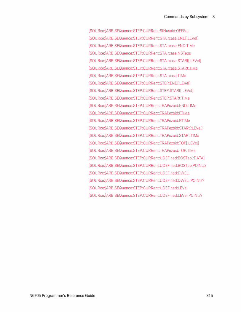
Commands by Subsystem 3
N6705 Programmer’s Reference Guide 315
[SOURce:]ARB:SEQuence:STEP:CURRent:SINusoid:OFFSet
[SOURce:]ARB:SEQuence:STEP:CURRent:STAircase:END[:LEVel]
[SOURce:]ARB:SEQuence:STEP:CURRent:STAircase:END:TIMe
[SOURce:]ARB:SEQuence:STEP:CURRent:STAircase:NSTeps
[SOURce:]ARB:SEQuence:STEP:CURRent:STAircase:STARt[:LEVel]
[SOURce:]ARB:SEQuence:STEP:CURRent:STAircase:STARt:TIMe
[SOURce:]ARB:SEQuence:STEP:CURRent:STAircase:TIMe
[SOURce:]ARB:SEQuence:STEP:CURRent:STEP:END[:LEVel]
[SOURce:]ARB:SEQuence:STEP:CURRent:STEP:STARt[:LEVel]
[SOURce:]ARB:SEQuence:STEP:CURRent:STEP:STARt:TIMe
[SOURce:]ARB:SEQuence:STEP:CURRent:TRAPezoid:END:TIMe
[SOURce:]ARB:SEQuence:STEP:CURRent:TRAPezoid:FTIMe
[SOURce:]ARB:SEQuence:STEP:CURRent:TRAPezoid:RTIMe
[SOURce:]ARB:SEQuence:STEP:CURRent:TRAPezoid:STARt[:LEVel]
[SOURce:]ARB:SEQuence:STEP:CURRent:TRAPezoid:STARt:TIMe
[SOURce:]ARB:SEQuence:STEP:CURRent:TRAPezoid:TOP[:LEVel]
[SOURce:]ARB:SEQuence:STEP:CURRent:TRAPezoid:TOP:TIMe
[SOURce:]ARB:SEQuence:STEP:CURRent:UDEFined:BOSTep[:DATA]
[SOURce:]ARB:SEQuence:STEP:CURRent:UDEFined:BOSTep:POINts?
[SOURce:]ARB:SEQuence:STEP:CURRent:UDEFined:DWELl
[SOURce:]ARB:SEQuence:STEP:CURRent:UDEFined:DWELl:POINts?
[SOURce:]ARB:SEQuence:STEP:CURRent:UDEFined:LEVel
[SOURce:]ARB:SEQuence:STEP:CURRent:UDEFined:LEVel:POINts?
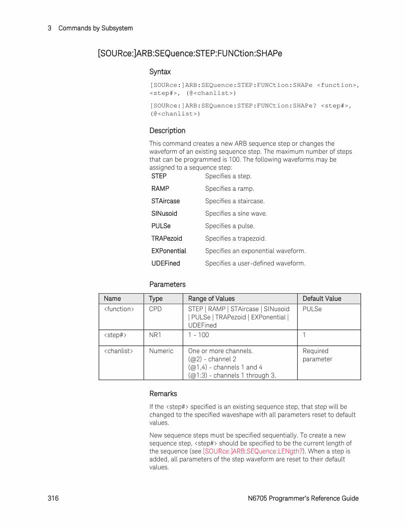
3 Commands by Subsystem
316 N6705 Programmer’s Reference Guide
[SOURce:]ARB:SEQuence:STEP:FUNCtion:SHAPe
Syntax
[SOURce:]ARB:SEQuence:STEP:FUNCtion:SHAPe <function>, <step#>, (@<chanlist>)
[SOURce:]ARB:SEQuence:STEP:FUNCtion:SHAPe? <step#>, (@<chanlist>)
Description
This command creates a new ARB sequence step or changes the waveform of an existing sequence step. The maximum number of steps that can be programmed is 100. The following waveforms may be assigned to a sequence step: STEP Specifies a step.
RAMP Specifies a ramp.
STAircase Specifies a staircase.
SINusoid Specifies a sine wave.
PULSe Specifies a pulse.
TRAPezoid Specifies a trapezoid.
EXPonential Specifies an exponential waveform.
UDEFined Specifies a user-defined waveform.
Parameters
Name Type Range of Values Default Value
<function> CPD STEP | RAMP | STAircase | SINusoid | PULSe | TRAPezoid | EXPonential | UDEFined
PULSe
<step#> NR1 1 - 100 1
<chanlist> Numeric One or more channels. (@2) - channel 2 (@1,4) - channels 1 and 4 (@1:3) - channels 1 through 3.
Required parameter
Remarks
If the <step#> specified is an existing sequence step, that step will be changed to the specified waveshape with all parameters reset to default values.
New sequence steps must be specified sequentially. To create a new sequence step, <step#> should be specified to be the current length of the sequence (see [SOURce:]ARB:SEQuence:LENgth?). When a step is added, all parameters of the step waveform are reset to their default values.
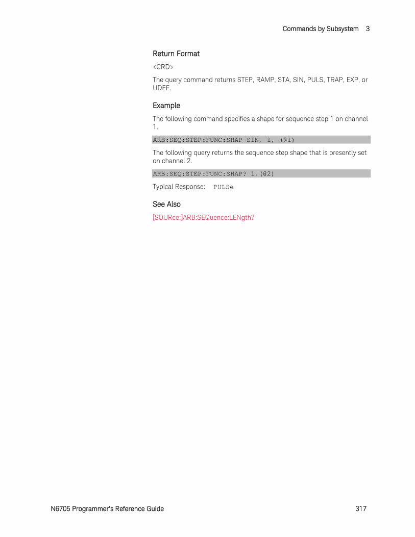
Commands by Subsystem 3
N6705 Programmer’s Reference Guide 317
Return Format
<CRD>
The query command returns STEP, RAMP, STA, SIN, PULS, TRAP, EXP, or UDEF.
Example
The following command specifies a shape for sequence step 1 on channel 1.
ARB:SEQ:STEP:FUNC:SHAP SIN, 1, (@1)
The following query returns the sequence step shape that is presently set on channel 2.
ARB:SEQ:STEP:FUNC:SHAP? 1,(@2)
Typical Response: PULSe
See Also
[SOURce:]ARB:SEQuence:LENgth?
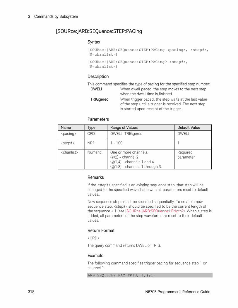
3 Commands by Subsystem
318 N6705 Programmer’s Reference Guide
[SOURce:]ARB:SEQuence:STEP:PACing
Syntax
[SOURce:]ARB:SEQuence:STEP:PACing <pacing>, <step#>, (@<chanlist>)
[SOURce:]ARB:SEQuence:STEP:PACing? <step#>, (@<chanlist>)
Description
This command specifies the type of pacing for the specified step number: DWELl When dwell paced, the step moves to the next step
when the dwell time is finished. TRIGgered When trigger paced, the step waits at the last value
of the step until a trigger is received. The next step is started upon receipt of the trigger.
Parameters
Name Type Range of Values Default Value
<pacing> CPD DWELl | TRIGgered DWELl
<step#> NR1 1 - 100 1
<chanlist> Numeric One or more channels. (@2) - channel 2 (@1,4) - channels 1 and 4 (@1:3) - channels 1 through 3.
Required parameter
Remarks
If the <step#> specified is an existing sequence step, that step will be changed to the specified waveshape with all parameters reset to default values..
New sequence steps must be specified sequentially. To create a new sequence step, <step#> should be specified to be the current length of the sequence + 1 (see [SOURce:]ARB:SEQuence:LENgth?). When a step is added, all parameters of the step waveform are reset to their default values.
Return Format
<CRD>
The query command returns DWEL or TRIG.
Example
The following command specifies trigger pacing for sequence step 1 on channel 1.
ARB:SEQ:STEP:PAC TRIG, 1,(@1)

Commands by Subsystem 3
N6705 Programmer’s Reference Guide 319
The following query returns the sequence step shape that is presently set on channel 2.
ARB:SEQ:STEP:PAC? 1,(@2)
Typical Response: DWEL
See Also
[SOURce:]ARB:SEQuence:LENgth?
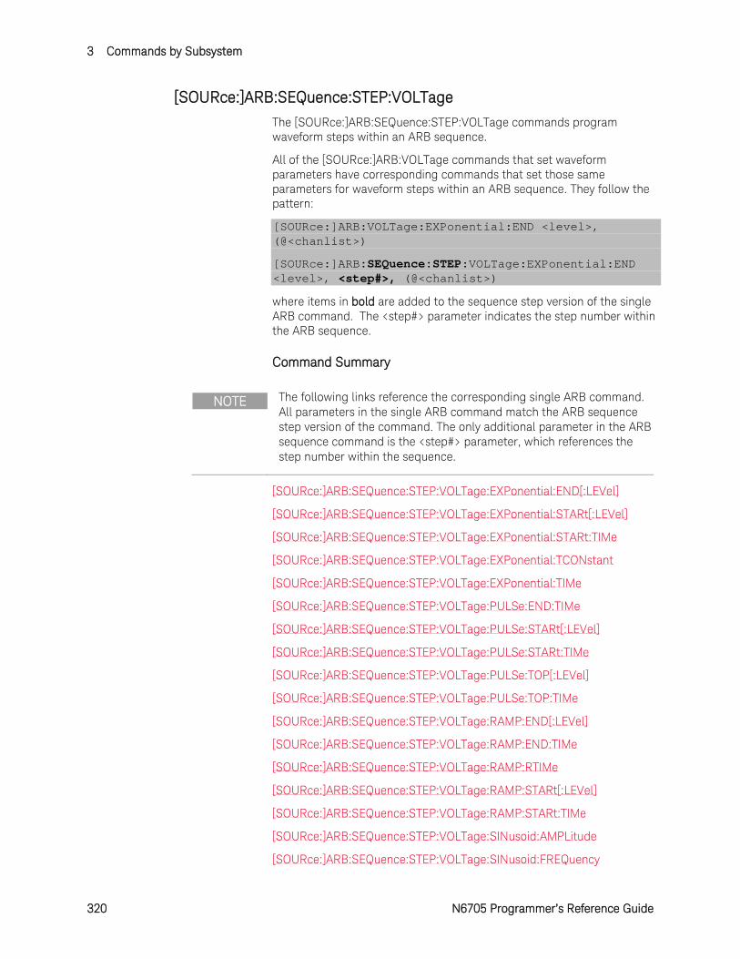
3 Commands by Subsystem
320 N6705 Programmer’s Reference Guide
[SOURce:]ARB:SEQuence:STEP:VOLTage
The [SOURce:]ARB:SEQuence:STEP:VOLTage commands program waveform steps within an ARB sequence.
All of the [SOURce:]ARB:VOLTage commands that set waveform parameters have corresponding commands that set those same parameters for waveform steps within an ARB sequence. They follow the pattern:
[SOURce:]ARB:VOLTage:EXPonential:END <level>, (@<chanlist>)
[SOURce:]ARB:SEQuence:STEP:VOLTage:EXPonential:END <level>, <step#>, (@<chanlist>)
where items in bold are added to the sequence step version of the single ARB command. The <step#> parameter indicates the step number within the ARB sequence.
Command Summary
NOTE The following links reference the corresponding single ARB command. All parameters in the single ARB command match the ARB sequence step version of the command. The only additional parameter in the ARB sequence command is the <step#> parameter, which references the step number within the sequence.
[SOURce:]ARB:SEQuence:STEP:VOLTage:EXPonential:END[:LEVel]
[SOURce:]ARB:SEQuence:STEP:VOLTage:EXPonential:STARt[:LEVel]
[SOURce:]ARB:SEQuence:STEP:VOLTage:EXPonential:STARt:TIMe
[SOURce:]ARB:SEQuence:STEP:VOLTage:EXPonential:TCONstant
[SOURce:]ARB:SEQuence:STEP:VOLTage:EXPonential:TIMe
[SOURce:]ARB:SEQuence:STEP:VOLTage:PULSe:END:TIMe
[SOURce:]ARB:SEQuence:STEP:VOLTage:PULSe:STARt[:LEVel]
[SOURce:]ARB:SEQuence:STEP:VOLTage:PULSe:STARt:TIMe
[SOURce:]ARB:SEQuence:STEP:VOLTage:PULSe:TOP[:LEVel]
[SOURce:]ARB:SEQuence:STEP:VOLTage:PULSe:TOP:TIMe
[SOURce:]ARB:SEQuence:STEP:VOLTage:RAMP:END[:LEVel]
[SOURce:]ARB:SEQuence:STEP:VOLTage:RAMP:END:TIMe
[SOURce:]ARB:SEQuence:STEP:VOLTage:RAMP:RTIMe
[SOURce:]ARB:SEQuence:STEP:VOLTage:RAMP:STARt[:LEVel]
[SOURce:]ARB:SEQuence:STEP:VOLTage:RAMP:STARt:TIMe
[SOURce:]ARB:SEQuence:STEP:VOLTage:SINusoid:AMPLitude
[SOURce:]ARB:SEQuence:STEP:VOLTage:SINusoid:FREQuency
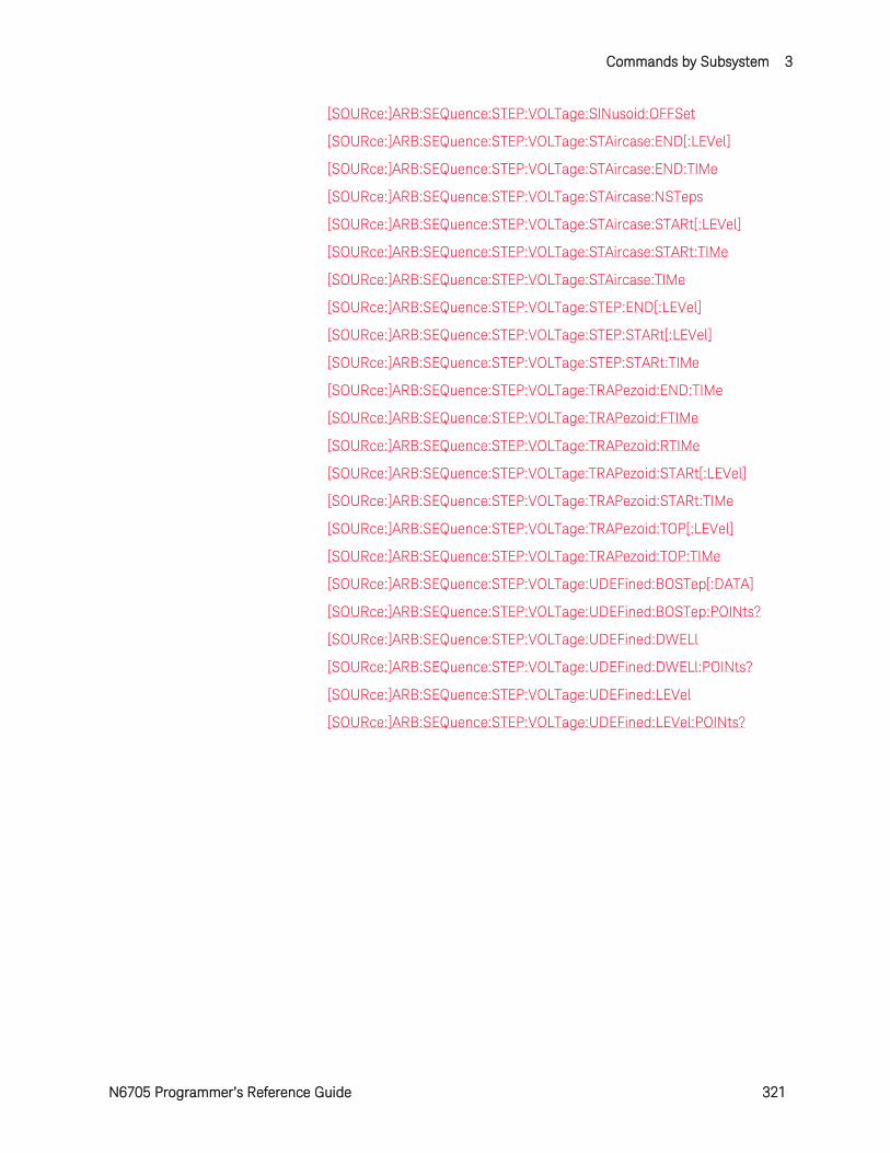
Commands by Subsystem 3
N6705 Programmer’s Reference Guide 321
[SOURce:]ARB:SEQuence:STEP:VOLTage:SINusoid:OFFSet
[SOURce:]ARB:SEQuence:STEP:VOLTage:STAircase:END[:LEVel]
[SOURce:]ARB:SEQuence:STEP:VOLTage:STAircase:END:TIMe
[SOURce:]ARB:SEQuence:STEP:VOLTage:STAircase:NSTeps
[SOURce:]ARB:SEQuence:STEP:VOLTage:STAircase:STARt[:LEVel]
[SOURce:]ARB:SEQuence:STEP:VOLTage:STAircase:STARt:TIMe
[SOURce:]ARB:SEQuence:STEP:VOLTage:STAircase:TIMe
[SOURce:]ARB:SEQuence:STEP:VOLTage:STEP:END[:LEVel]
[SOURce:]ARB:SEQuence:STEP:VOLTage:STEP:STARt[:LEVel]
[SOURce:]ARB:SEQuence:STEP:VOLTage:STEP:STARt:TIMe
[SOURce:]ARB:SEQuence:STEP:VOLTage:TRAPezoid:END:TIMe
[SOURce:]ARB:SEQuence:STEP:VOLTage:TRAPezoid:FTIMe
[SOURce:]ARB:SEQuence:STEP:VOLTage:TRAPezoid:RTIMe
[SOURce:]ARB:SEQuence:STEP:VOLTage:TRAPezoid:STARt[:LEVel]
[SOURce:]ARB:SEQuence:STEP:VOLTage:TRAPezoid:STARt:TIMe
[SOURce:]ARB:SEQuence:STEP:VOLTage:TRAPezoid:TOP[:LEVel]
[SOURce:]ARB:SEQuence:STEP:VOLTage:TRAPezoid:TOP:TIMe
[SOURce:]ARB:SEQuence:STEP:VOLTage:UDEFined:BOSTep[:DATA]
[SOURce:]ARB:SEQuence:STEP:VOLTage:UDEFined:BOSTep:POINts?
[SOURce:]ARB:SEQuence:STEP:VOLTage:UDEFined:DWELl
[SOURce:]ARB:SEQuence:STEP:VOLTage:UDEFined:DWELl:POINts?
[SOURce:]ARB:SEQuence:STEP:VOLTage:UDEFined:LEVel
[SOURce:]ARB:SEQuence:STEP:VOLTage:UDEFined:LEVel:POINts?
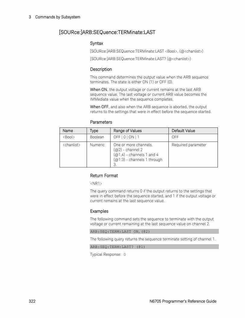
3 Commands by Subsystem
322 N6705 Programmer’s Reference Guide
[SOURce:]ARB:SEQuence:TERMinate:LAST
Syntax
[SOURce:]ARB:SEQuence:TERMinate:LAST <Bool>, (@<chanlist>)
[SOURce:]ARB:SEQuence:TERMinate:LAST? (@<chanlist>)
Description
This command determines the output value when the ARB sequence terminates. The state is either ON (1) or OFF (0).
When ON, the output voltage or current remains at the last ARB sequence value. The last voltage or current ARB value becomes the IMMediate value when the sequence completes.
When OFF, and also when the ARB sequence is aborted, the output returns to the settings that were in effect before the sequence started.
Parameters
Name Type Range of Values Default Value
<Bool> Boolean OFF | 0 | ON | 1 OFF
<chanlist> Numeric One or more channels. (@2) - channel 2 (@1,4) - channels 1 and 4 (@1:3) - channels 1 through 3.
Required parameter
Return Format
<NR1>
The query command returns 0 if the output returns to the settings that were in effect before the sequence started, and 1 if the output voltage or current remains at the last sequence value.
Examples
The following command sets the sequence to terminate with the output voltage or current remaining at the last sequence value on channel 2.
ARB:SEQ:TERM:LAST ON,(@2)
The following query returns the sequence terminate setting of channel 1.
ARB:SEQ:TERM:LAST? (@1)
Typical Response: 0
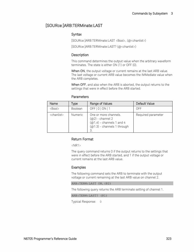
Commands by Subsystem 3
N6705 Programmer’s Reference Guide 323
[SOURce:]ARB:TERMinate:LAST
Syntax
[SOURce:]ARB:TERMinate:LAST <Bool>, (@<chanlist>)
[SOURce:]ARB:TERMinate:LAST? (@<chanlist>)
Description
This command determines the output value when the arbitrary waveform terminates. The state is either ON (1) or OFF (0).
When ON, the output voltage or current remains at the last ARB value. The last voltage or current ARB value becomes the IMMediate value when the ARB completes.
When OFF, and also when the ARB is aborted, the output returns to the settings that were in effect before the ARB started.
Parameters
Name Type Range of Values Default Value
<Bool> Boolean OFF | 0 | ON | 1 OFF
<chanlist> Numeric One or more channels. (@2) - channel 2 (@1,4) - channels 1 and 4 (@1:3) - channels 1 through 3.
Required parameter
Return Format
<NR1>
The query command returns 0 if the output returns to the settings that were in effect before the ARB started, and 1 if the output voltage or current remains at the last ARB value.
Examples
The following command sets the ARB to terminate with the output voltage or current remaining at the last ARB value on channel 2.
ARB:TERM:LAST ON,(@2)
The following query returns the ARB terminate setting of channel 1.
ARB:TERM:LAST? (@1)
Typical Response: 0
3 Commands by Subsystem
324 N6705 Programmer’s Reference Guide
[SOURce:]ARB:VOLTage:CDWell[:LEVel]
Syntax
[SOURce:]ARB:VOLTage:CDWell[:LEVel] <voltage>,<voltage>, (@<chanlist>)
[SOURce:]ARB:VOLTage:CDWell[:LEVel]? (@<chanlist>)
Description
This command specifies the level of each point of a constant dwell ARB. Current and voltage CD ARBs share settings, so setting the voltage CD ARB resets the current CD ARB level to its default value and vice-versa. A comma-delimited list of up to 65,535 points may be programmed.
For better performance, the list of voltage points can be sent as a definite length binary block instead of an ASCII list.
Parameters
Name Type Range of Values Default Value
<voltage> NRf or <block>
0 – maximum The maximum value is dependent on the voltage rating of the power module.
1 point set to the minimum programmable value
<chanlist> Numeric One or more channels. (@2) - channel 2 (@1,4) - channels 1 and 4 (@1:3) - channels 1 through 3.
Required parameter
Return Format
The return format depends on the settings of the FORMat:BORDer and FORMat[:DATA] commands. When the data format is set to ASCII, returned values are comma separated. Only one channel can be queried when the format is ASCII. When the data format is set to REAL, data is returned as single precision floating point numbers in definite length arbitrary block response format. Each block contains all the records for one of the channels given in the <chanlist> parameter. If multiple channels are given, then each definite length arbitrary block of data is separated by a comma.
<NR3> [,<NR3>] or <block> [,<block>]
Examples
The following command programs a constant-dwell voltage ARB. The ARB contains 5 points and is on channel 1.
ARB:VOLT:CDW 5,4,3,2,1,(@1)
The following query returns the constant-dwell voltage settings of
Commands by Subsystem 3
N6705 Programmer’s Reference Guide 325
channel 1.
ARB:VOLT:CDW? (@1)
See Also
[SOURce:]ARB:VOLTage:CDWell:DWELl
FORMat:BORDer
FORMat[:DATA]
3 Commands by Subsystem
326 N6705 Programmer’s Reference Guide
[SOURce:]ARB:VOLTage:CDWell:DWELl
Syntax
[SOURce:]ARB:VOLTage:CDWell:DWELl <time>, (@<chanlist>)
[SOURce:]ARB:VOLTage:CDWell:DWELl? (@<chanlist>)
Description
This command specifies the dwell time for each point of a constant-dwell ARB. Current and voltage CD ARBs share settings, so setting this parameter for a current CD ARB also changes the voltage dwell value and vice versa. Programmed values can range from 10.24 microseconds to 0.30 seconds. Values are rounded to the nearest 10.24-microsecond increment.
Parameters
Name Type Range of Values Default Value
<time> NRf 0.00001024 - 0.30 0.001 seconds
<chanlist> Numeric One or more channels. (@2) - channel 2 (@1,4) - channels 1 and 4 (@1:3) - channels 1 through 3.
Required parameter
Remarks
The maximum repeat count for CD ARBs is 256. See [SOURce:]ARB:COUNt.
Return Format
<NR3>
The query command returns the programmed dwell time in the form +n.nnnnnnE+nn. Multiple responses are separated by commas.
Examples
The following command programs constant-dwell time of 0.2 seconds on channel 1.
ARB:VOLT:CDW:DWEL 0.2,(@1)
The following query returns the constant-dwell time of channel 1.
ARB:VOLT:CDW:DWEL? (@1)
Typical Response: +1.000000E-03
See Also
[SOURce:]ARB:VOLTage:CDWell[:LEVel]
Commands by Subsystem 3
N6705 Programmer’s Reference Guide 327
[SOURce:]ARB:VOLTage:CDWell:POINts?
Syntax
[SOURce:]ARB:VOLTage:CDWell:POINts? (@<chanlist>)
Description
This query returns the number of voltage points in a constant-dwell ARB.
Parameters
Name Type Range of Values Default Value
<chanlist> Numeric One or more channels. (@2) - channel 2 (@1,4) - channels 1 and 4 (@1:3) - channels 1 through 3.
Required parameter
Return Format
<NR3>
Returns the number of points in the form +n.nnnnnnE+nn. Multiple responses are separated by commas.
Examples
The following query returns the number of voltage points of channel 1.
ARB:VOLT:CDW:POIN? (@1)
Typical Response: +4.376500E+04
See Also
[SOURce:]ARB:CURRent:CDWell:POINts?
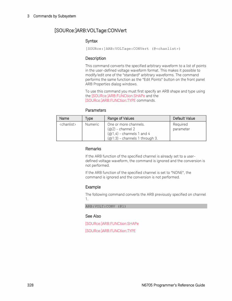
3 Commands by Subsystem
328 N6705 Programmer’s Reference Guide
[SOURce:]ARB:VOLTage:CONVert
Syntax
[SOURce:]ARB:VOLTage:CONVert (@<chanlist>)
Description
This command converts the specified arbitrary waveform to a list of points in the user-defined voltage waveform format. This makes it possible to modify/edit one of the "standard" arbitrary waveforms. The command performs the same function as the "Edit Points" button on the front panel ARB Properties dialog windows.
To use this command you must first specify an ARB shape and type using the [SOURce:]ARB:FUNCtion:SHAPe and the [SOURce:]ARB:FUNCtion:TYPE commands.
Parameters
Name Type Range of Values Default Value
<chanlist> Numeric One or more channels. (@2) - channel 2 (@1,4) - channels 1 and 4 (@1:3) - channels 1 through 3.
Required parameter
Remarks
If the ARB function of the specified channel is already set to a user-defined voltage waveform, the command is ignored and the conversion is not performed.
If the ARB function of the specified channel is set to "NONE", the command is ignored and the conversion is not performed.
Example
The following command converts the ARB previously specified on channel 1.
ARB:VOLT:CONV (@1)
See Also
[SOURce:]ARB:FUNCtion:SHAPe
[SOURce:]ARB:FUNCtion:TYPE
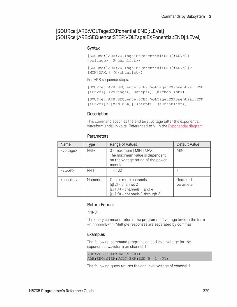
Commands by Subsystem 3
N6705 Programmer’s Reference Guide 329
[SOURce:]ARB:VOLTage:EXPonential:END[:LEVel] [SOURce:]ARB:SEQuence:STEP:VOLTage:EXPonential:END[:LEVel]
Syntax
[SOURce:]ARB:VOLTage:EXPonential:END[:LEVel] <voltage> (@<chanlist>)
[SOURce:]ARB:VOLTage:EXPonential:END[:LEVel]? [MIN|MAX,] (@<chanlist>)
For ARB sequence steps:
[SOURce:]ARB:SEQuence:STEP:VOLTage:EXPonential:END [:LEVel] <voltage>, <step#>, (@<chanlist>)
[SOURce:]ARB:SEQuence:STEP:VOLTage:EXPonential:END [:LEVel]? [MIN|MAX,] <step#>, (@<chanlist>)
Description
This command specifies the end level voltage (after the exponential waveform ends) in volts. Referenced to V1 in the Exponential diagram.
Parameters
Name Type Range of Values Default Value
<voltage> NRf+ 0 - maximum | MIN | MAX The maximum value is dependent on the voltage rating of the power module.
MIN
<step#> NR1 1 - 100 1
<chanlist> Numeric One or more channels. (@2) - channel 2 (@1,4) - channels 1 and 4 (@1:3) - channels 1 through 3.
Required parameter
Return Format
<NR3>
The query command returns the programmed voltage level in the form +n.nnnnnnE+nn. Multiple responses are separated by commas.
Examples
The following command programs an end level voltage for the exponential waveform on channel 1.
ARB:VOLT:EXP:END 5,(@1) ARB:SEQ:STEP:VOLT:EXP:END 5, 1,(@1)
The following query returns the end level voltage of channel 1.

3 Commands by Subsystem
330 N6705 Programmer’s Reference Guide
ARB:VOLT:EXP:END? (@1) ARB:SEQ:STEP:VOLT:EXP:END? 1,(@1)
Typical Response: +5.000000E+00
See Also
[SOURce:]ARB:VOLTage:EXPonential:STARt[:LEVel]
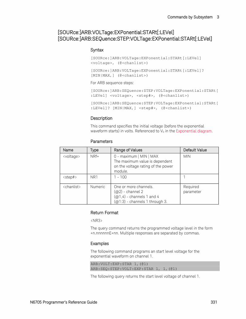
Commands by Subsystem 3
N6705 Programmer’s Reference Guide 331
[SOURce:]ARB:VOLTage:EXPonential:STARt[:LEVel] [SOURce:]ARB:SEQuence:STEP:VOLTage:EXPonential:STARt[:LEVel]
Syntax
[SOURce:]ARB:VOLTage:EXPonential:STARt[:LEVel] <voltage>, (@<chanlist>)
[SOURce:]ARB:VOLTage:EXPonential:STARt[:LEVel]? [MIN|MAX,] (@<chanlist>)
For ARB sequence steps:
[SOURce:]ARB:SEQuence:STEP:VOLTage:EXPonential:STARt[:LEVel] <voltage>, <step#>, (@<chanlist>)
[SOURce:]ARB:SEQuence:STEP:VOLTage:EXPonential:STARt[:LEVel]? [MIN|MAX,] <step#>, (@<chanlist>)
Description
This command specifies the initial voltage (before the exponential waveform starts) in volts. Referenced to V0 in the Exponential diagram.
Parameters
Name Type Range of Values Default Value
<voltage> NRf+ 0 - maximum | MIN | MAX The maximum value is dependent on the voltage rating of the power module.
MIN
<step#> NR1 1 - 100 1
<chanlist> Numeric One or more channels. (@2) - channel 2 (@1,4) - channels 1 and 4 (@1:3) - channels 1 through 3.
Required parameter
Return Format
<NR3>
The query command returns the programmed voltage level in the form +n.nnnnnnE+nn. Multiple responses are separated by commas.
Examples
The following command programs an start level voltage for the exponential waveform on channel 1.
ARB:VOLT:EXP:STAR 1,(@1) ARB:SEQ:STEP:VOLT:EXP:STAR 1, 1,(@1)
The following query returns the start level voltage of channel 1.

3 Commands by Subsystem
332 N6705 Programmer’s Reference Guide
ARB:VOLT:EXP:STAR? (@1) ARB:SEQ:STEP:VOLT:EXP:STAR? 1,(@1)
Typical Response: +1.000000E+00
See Also
[SOURce:]ARB:VOLTage:EXPonential:STARt:TIMe
[SOURce:]ARB:VOLTage:EXPonential:END[:LEVel]
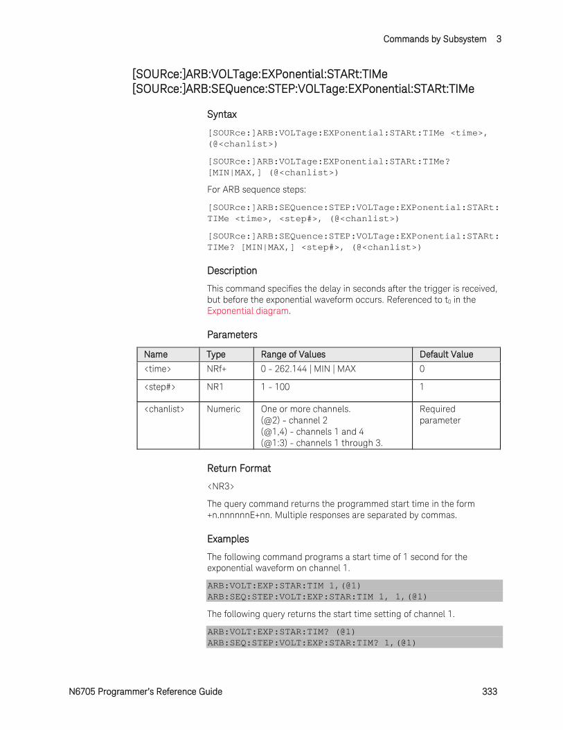
Commands by Subsystem 3
N6705 Programmer’s Reference Guide 333
[SOURce:]ARB:VOLTage:EXPonential:STARt:TIMe [SOURce:]ARB:SEQuence:STEP:VOLTage:EXPonential:STARt:TIMe
Syntax
[SOURce:]ARB:VOLTage:EXPonential:STARt:TIMe <time>, (@<chanlist>)
[SOURce:]ARB:VOLTage:EXPonential:STARt:TIMe? [MIN|MAX,] (@<chanlist>)
For ARB sequence steps:
[SOURce:]ARB:SEQuence:STEP:VOLTage:EXPonential:STARt:TIMe <time>, <step#>, (@<chanlist>)
[SOURce:]ARB:SEQuence:STEP:VOLTage:EXPonential:STARt:TIMe? [MIN|MAX,] <step#>, (@<chanlist>)
Description
This command specifies the delay in seconds after the trigger is received, but before the exponential waveform occurs. Referenced to t0 in the Exponential diagram.
Parameters
Name Type Range of Values Default Value
<time> NRf+ 0 - 262.144 | MIN | MAX 0
<step#> NR1 1 - 100 1
<chanlist> Numeric One or more channels. (@2) - channel 2 (@1,4) - channels 1 and 4 (@1:3) - channels 1 through 3.
Required parameter
Return Format
<NR3>
The query command returns the programmed start time in the form +n.nnnnnnE+nn. Multiple responses are separated by commas.
Examples
The following command programs a start time of 1 second for the exponential waveform on channel 1.
ARB:VOLT:EXP:STAR:TIM 1,(@1) ARB:SEQ:STEP:VOLT:EXP:STAR:TIM 1, 1,(@1)
The following query returns the start time setting of channel 1.
ARB:VOLT:EXP:STAR:TIM? (@1) ARB:SEQ:STEP:VOLT:EXP:STAR:TIM? 1,(@1)
3 Commands by Subsystem
334 N6705 Programmer’s Reference Guide
Typical Response: +1.000000E+00
See Also
[SOURce:]ARB:VOLTage:EXPonential:STARt[:LEVel]
[SOURce:]ARB:VOLTage:EXPonential:TIMe
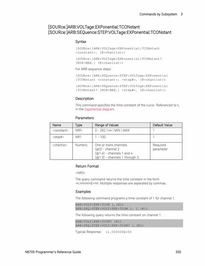
Commands by Subsystem 3
N6705 Programmer’s Reference Guide 335
[SOURce:]ARB:VOLTage:EXPonential:TCONstant [SOURce:]ARB:SEQuence:STEP:VOLTage:EXPonential:TCONstant
Syntax
[SOURce:]ARB:VOLTage:EXPonential:TCONstant <constant>, (@<chanlist>)
[SOURce:]ARB:VOLTage:EXPonential:TCONstant? [MIN|MAX,] (@<chanlist>)
For ARB sequence steps:
[SOURce:]ARB:SEQuence:STEP:VOLTage:EXPonential :TCONstant <constant>, <step#>, (@<chanlist>)
[SOURce:]ARB:SEQuence:STEP:VOLTage:EXPonential :TCONstant? [MIN|MAX,] <step#>, (@<chanlist>)
Description
This command specifies the time constant of the curve. Referenced to tc in the Exponential diagram.
Parameters
Name Type Range of Values Default Value
<constant> NRf+ 0 - 262.144 | MIN | MAX 1
<step#> NR1 1 - 100 1
<chanlist> Numeric One or more channels. (@2) - channel 2 (@1,4) - channels 1 and 4 (@1:3) - channels 1 through 3.
Required parameter
Return Format
<NR3>
The query command returns the time constant in the form +n.nnnnnnE+nn. Multiple responses are separated by commas.
Examples
The following command programs a time constant of 1 for channel 1.
ARB:VOLT:EXP:TCON 1,(@1) ARB:SEQ:STEP:VOLT:EXP:TCON 1, 1,(@1)
The following query returns the time constant on channel 1.
ARB:VOLT:EXP:TCON? (@1) ARB:SEQ:STEP:VOLT:EXP:TCON? 1,(@1)
Typical Response: +1.000000E+00
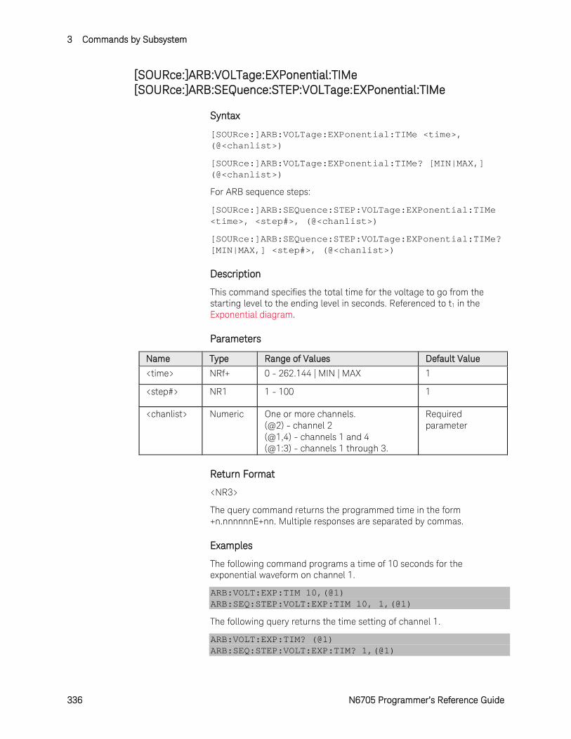
3 Commands by Subsystem
336 N6705 Programmer’s Reference Guide
[SOURce:]ARB:VOLTage:EXPonential:TIMe [SOURce:]ARB:SEQuence:STEP:VOLTage:EXPonential:TIMe
Syntax
[SOURce:]ARB:VOLTage:EXPonential:TIMe <time>, (@<chanlist>)
[SOURce:]ARB:VOLTage:EXPonential:TIMe? [MIN|MAX,] (@<chanlist>)
For ARB sequence steps:
[SOURce:]ARB:SEQuence:STEP:VOLTage:EXPonential:TIMe <time>, <step#>, (@<chanlist>)
[SOURce:]ARB:SEQuence:STEP:VOLTage:EXPonential:TIMe? [MIN|MAX,] <step#>, (@<chanlist>)
Description
This command specifies the total time for the voltage to go from the starting level to the ending level in seconds. Referenced to t1 in the Exponential diagram.
Parameters
Name Type Range of Values Default Value
<time> NRf+ 0 - 262.144 | MIN | MAX 1
<step#> NR1 1 - 100 1
<chanlist> Numeric One or more channels. (@2) - channel 2 (@1,4) - channels 1 and 4 (@1:3) - channels 1 through 3.
Required parameter
Return Format
<NR3>
The query command returns the programmed time in the form +n.nnnnnnE+nn. Multiple responses are separated by commas.
Examples
The following command programs a time of 10 seconds for the exponential waveform on channel 1.
ARB:VOLT:EXP:TIM 10,(@1) ARB:SEQ:STEP:VOLT:EXP:TIM 10, 1,(@1)
The following query returns the time setting of channel 1.
ARB:VOLT:EXP:TIM? (@1) ARB:SEQ:STEP:VOLT:EXP:TIM? 1,(@1)

Commands by Subsystem 3
N6705 Programmer’s Reference Guide 337
Typical Response: +1.000000E+00
See Also
[SOURce:]ARB:VOLTage:EXPonential:STARt:TIMe
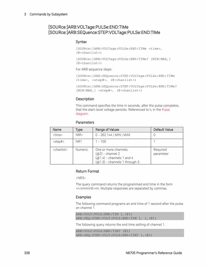
3 Commands by Subsystem
338 N6705 Programmer’s Reference Guide
[SOURce:]ARB:VOLTage:PULSe:END:TIMe [SOURce:]ARB:SEQuence:STEP:VOLTage:PULSe:END:TIMe
Syntax
[SOURce:]ARB:VOLTage:PULSe:END:TIMe <time>, (@<chanlist>)
[SOURce:]ARB:VOLTage:PULSe:END:TIMe? [MIN|MAX,] (@<chanlist>)
For ARB sequence steps:
[SOURce:]ARB:SEQuence:STEP:VOLTage:PULSe:END:TIMe <time>, <step#>, (@<chanlist>)
[SOURce:]ARB:SEQuence:STEP:VOLTage:PULSe:END:TIMe? [MIN|MAX,] <step#>, (@<chanlist>)
Description
This command specifies the time in seconds, after the pulse completes, that the start-level voltage persists. Referenced to t2 in the Pulse diagram.
Parameters
Name Type Range of Values Default Value
<time> NRf+ 0 - 262.144 | MIN | MAX 0
<step#> NR1 1 - 100 1
<chanlist> Numeric One or more channels. (@2) - channel 2 (@1,4) - channels 1 and 4 (@1:3) - channels 1 through 3.
Required parameter
Return Format
<NR3>
The query command returns the programmed end time in the form +n.nnnnnnE+nn. Multiple responses are separated by commas.
Examples
The following command programs an end time of 1 second after the pulse on channel 1.
ARB:VOLT:PULS:END:TIM 1,(@1) ARB:SEQ:STEP:VOLT:PULS:END:TIM 1, 1,(@1)
The following query returns the end time setting of channel 1.
ARB:VOLT:PULS:END:TIM? (@1) ARB:SEQ:STEP:VOLT:PULS:END:TIM? 1,(@1)

Commands by Subsystem 3
N6705 Programmer’s Reference Guide 339
Typical Response: +1.000000E+00
See Also
[SOURce:]ARB:VOLTage:PULSe:STARt[:LEVel]
[SOURce:]ARB:VOLTage:PULSe:STARt:TIMe
[SOURce:]ARB:VOLTage:PULSe:TOP:TIMe
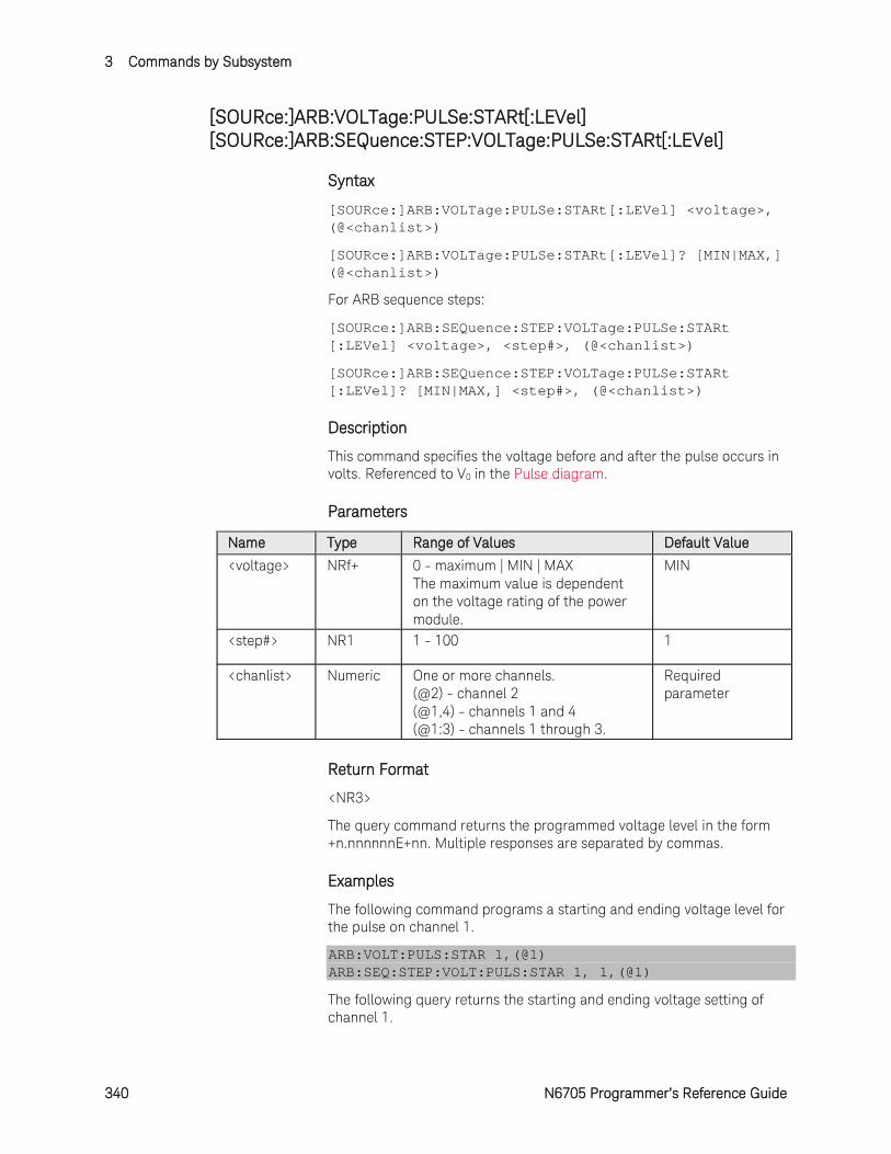
3 Commands by Subsystem
340 N6705 Programmer’s Reference Guide
[SOURce:]ARB:VOLTage:PULSe:STARt[:LEVel] [SOURce:]ARB:SEQuence:STEP:VOLTage:PULSe:STARt[:LEVel]
Syntax
[SOURce:]ARB:VOLTage:PULSe:STARt[:LEVel] <voltage>, (@<chanlist>)
[SOURce:]ARB:VOLTage:PULSe:STARt[:LEVel]? [MIN|MAX,] (@<chanlist>)
For ARB sequence steps:
[SOURce:]ARB:SEQuence:STEP:VOLTage:PULSe:STARt [:LEVel] <voltage>, <step#>, (@<chanlist>)
[SOURce:]ARB:SEQuence:STEP:VOLTage:PULSe:STARt [:LEVel]? [MIN|MAX,] <step#>, (@<chanlist>)
Description
This command specifies the voltage before and after the pulse occurs in volts. Referenced to V0 in the Pulse diagram.
Parameters
Name Type Range of Values Default Value
<voltage> NRf+ 0 - maximum | MIN | MAX The maximum value is dependent on the voltage rating of the power module.
MIN
<step#> NR1 1 - 100 1
<chanlist> Numeric One or more channels. (@2) - channel 2 (@1,4) - channels 1 and 4 (@1:3) - channels 1 through 3.
Required parameter
Return Format
<NR3>
The query command returns the programmed voltage level in the form +n.nnnnnnE+nn. Multiple responses are separated by commas.
Examples
The following command programs a starting and ending voltage level for the pulse on channel 1.
ARB:VOLT:PULS:STAR 1,(@1) ARB:SEQ:STEP:VOLT:PULS:STAR 1, 1,(@1)
The following query returns the starting and ending voltage setting of channel 1.

Commands by Subsystem 3
N6705 Programmer’s Reference Guide 341
ARB:VOLT:PULS:STAR? (@1) ARB:SEQ:STEP:VOLT:PULS:STAR? 1,(@1)
Typical Response: +1.000000E+00
See Also
[SOURce:]ARB:VOLTage:PULSe:STARt:TIMe
[SOURce:]ARB:VOLTage:PULse:TOP[:LEVel]

3 Commands by Subsystem
342 N6705 Programmer’s Reference Guide
[SOURce:]ARB:VOLTage:PULSe:STARt:TIMe [SOURce:]ARB:SEQuence:STEP:VOLTage:PULSe:STARt:TIMe
Syntax
[SOURce:]ARB:VOLTage:PULSe:STARt:TIMe <time>, (@<chanlist>)
[SOURce:]ARB:VOLTage:PULSe:STARt:TIMe? [MIN|MAX,] (@<chanlist>)
For ARB sequence steps:
[SOURce:]ARB:SEQuence:STEP:VOLTage:PULSe:STARt:TIMe <time>, <step#>, (@<chanlist>)
[SOURce:]ARB:SEQuence:STEP:VOLTage:PULSe:STARt:TIMe? [MIN|MAX,] <step#>, (@<chanlist>)
Description
This command specifies the delay in seconds after the trigger is received, but before the pulse occurs. Referenced to t0 in the Pulse diagram.
Parameters
Name Type Range of Values Default Value
<time> NRf+ 0 - 262.144 | MIN | MAX 0
<step#> NR1 1 - 100 1
<chanlist> Numeric One or more channels. (@2) - channel 2 (@1,4) - channels 1 and 4 (@1:3) - channels 1 through 3.
Required parameter
Return Format
<NR3>
The query command returns the programmed start time in the form +n.nnnnnnE+nn. Multiple responses are separated by commas.
Examples
The following command programs a start time of 1 second for the pulse on channel 1.
ARB:VOLT:PULS:STAR:TIM 1,(@1) ARB:SEQ:STEP:VOLT:PULS:STAR:TIM 1, 1,(@1)
The following query returns the start time setting of channel 1.
ARB:VOLT:PULS:STAR:TIM? (@1) ARB:SEQ:STEP:VOLT:PULS:STAR:TIM? 1,(@1)
Typical Response: +1.000000E+00

Commands by Subsystem 3
N6705 Programmer’s Reference Guide 343
See Also
[SOURce:]ARB:VOLTage:PULSe:STARt[:LEVel]
[SOURce:]ARB:VOLTage:PULSe:END:TIMe
[SOURce:]ARB:VOLTage:PULSe:TOP:TIMe
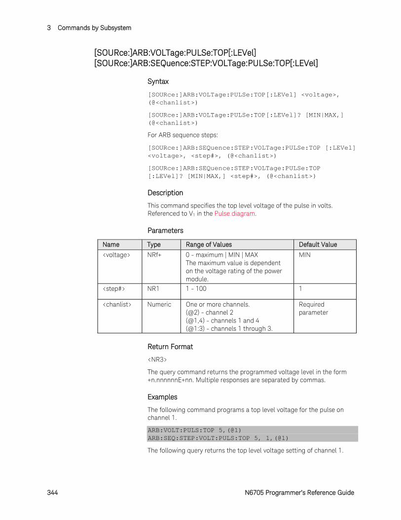
3 Commands by Subsystem
344 N6705 Programmer’s Reference Guide
[SOURce:]ARB:VOLTage:PULSe:TOP[:LEVel] [SOURce:]ARB:SEQuence:STEP:VOLTage:PULSe:TOP[:LEVel]
Syntax
[SOURce:]ARB:VOLTage:PULSe:TOP[:LEVel] <voltage>, (@<chanlist>)
[SOURce:]ARB:VOLTage:PULSe:TOP[:LEVel]? [MIN|MAX,] (@<chanlist>)
For ARB sequence steps:
[SOURce:]ARB:SEQuence:STEP:VOLTage:PULSe:TOP [:LEVel] <voltage>, <step#>, (@<chanlist>)
[SOURce:]ARB:SEQuence:STEP:VOLTage:PULSe:TOP [:LEVel]? [MIN|MAX,] <step#>, (@<chanlist>)
Description
This command specifies the top level voltage of the pulse in volts. Referenced to V1 in the Pulse diagram.
Parameters
Name Type Range of Values Default Value
<voltage> NRf+ 0 - maximum | MIN | MAX The maximum value is dependent on the voltage rating of the power module.
MIN
<step#> NR1 1 - 100 1
<chanlist> Numeric One or more channels. (@2) - channel 2 (@1,4) - channels 1 and 4 (@1:3) - channels 1 through 3.
Required parameter
Return Format
<NR3>
The query command returns the programmed voltage level in the form +n.nnnnnnE+nn. Multiple responses are separated by commas.
Examples
The following command programs a top level voltage for the pulse on channel 1.
ARB:VOLT:PULS:TOP 5,(@1) ARB:SEQ:STEP:VOLT:PULS:TOP 5, 1,(@1)
The following query returns the top level voltage setting of channel 1.
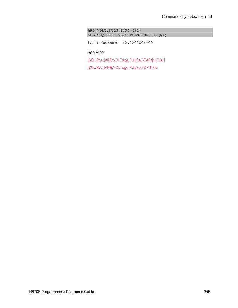
Commands by Subsystem 3
N6705 Programmer’s Reference Guide 345
ARB:VOLT:PULS:TOP? (@1) ARB:SEQ:STEP:VOLT:PULS:TOP? 1,(@1)
Typical Response: +5.000000E+00
See Also
[SOURce:]ARB:VOLTage:PULSe:STARt[:LEVel]
[SOURce:]ARB:VOLTage:PULSe:TOP:TIMe
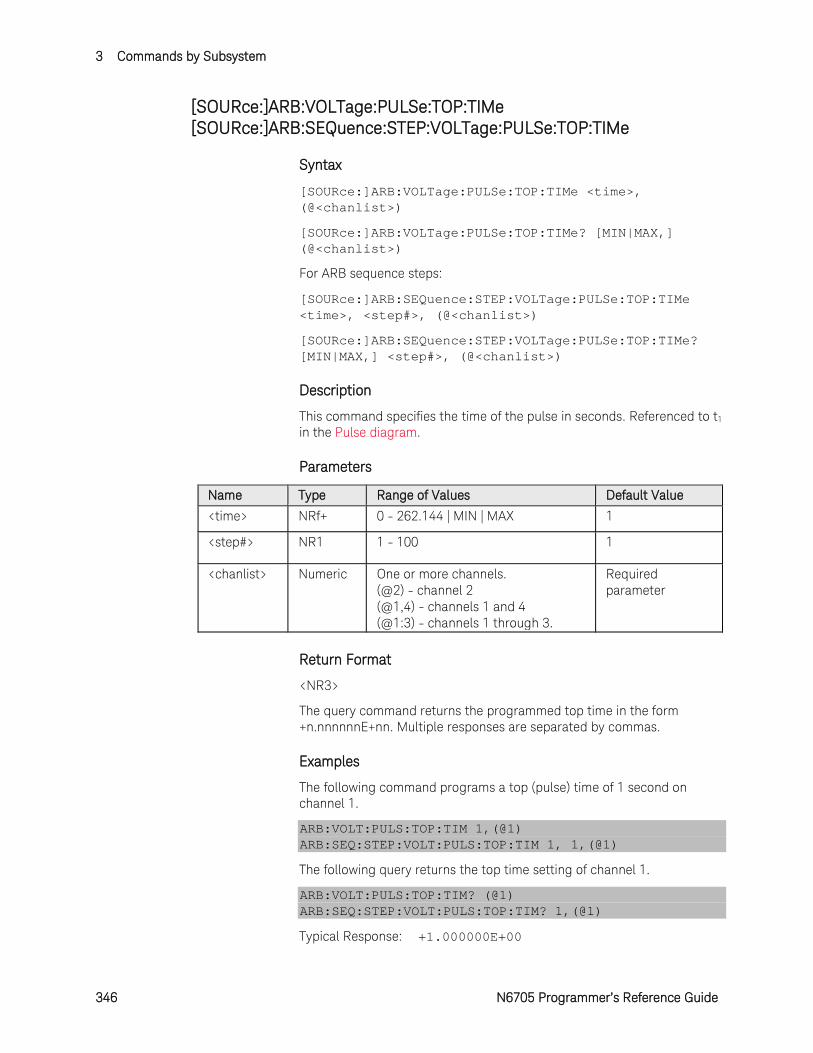
3 Commands by Subsystem
346 N6705 Programmer’s Reference Guide
[SOURce:]ARB:VOLTage:PULSe:TOP:TIMe [SOURce:]ARB:SEQuence:STEP:VOLTage:PULSe:TOP:TIMe
Syntax
[SOURce:]ARB:VOLTage:PULSe:TOP:TIMe <time>, (@<chanlist>)
[SOURce:]ARB:VOLTage:PULSe:TOP:TIMe? [MIN|MAX,] (@<chanlist>)
For ARB sequence steps:
[SOURce:]ARB:SEQuence:STEP:VOLTage:PULSe:TOP:TIMe <time>, <step#>, (@<chanlist>)
[SOURce:]ARB:SEQuence:STEP:VOLTage:PULSe:TOP:TIMe? [MIN|MAX,] <step#>, (@<chanlist>)
Description
This command specifies the time of the pulse in seconds. Referenced to t1 in the Pulse diagram.
Parameters
Name Type Range of Values Default Value
<time> NRf+ 0 - 262.144 | MIN | MAX 1
<step#> NR1 1 - 100 1
<chanlist> Numeric One or more channels. (@2) - channel 2 (@1,4) - channels 1 and 4 (@1:3) - channels 1 through 3.
Required parameter
Return Format
<NR3>
The query command returns the programmed top time in the form +n.nnnnnnE+nn. Multiple responses are separated by commas.
Examples
The following command programs a top (pulse) time of 1 second on channel 1.
ARB:VOLT:PULS:TOP:TIM 1,(@1) ARB:SEQ:STEP:VOLT:PULS:TOP:TIM 1, 1,(@1)
The following query returns the top time setting of channel 1.
ARB:VOLT:PULS:TOP:TIM? (@1) ARB:SEQ:STEP:VOLT:PULS:TOP:TIM? 1,(@1)
Typical Response: +1.000000E+00

Commands by Subsystem 3
N6705 Programmer’s Reference Guide 347
See Also
[SOURce:]ARB:VOLTage:PULse:TOP[:LEVel]
[SOURce:]ARB:VOLTage:PULSe:STARt:TIMe
[SOURce:]ARB:VOLTage:PULSe:END:TIMe

3 Commands by Subsystem
348 N6705 Programmer’s Reference Guide
[SOURce:]ARB:VOLTage:RAMP:END[:LEVel] [SOURce:]ARB:SEQuence:STEP:VOLTage:RAMP:END[:LEVel]
Syntax
[SOURce:]ARB:VOLTage:RAMP:END[:LEVel] <voltage>, (@<chanlist>)
[SOURce:]ARB:VOLTage:RAMP:END[:LEVel]? [MIN|MAX,] (@<chanlist>)
For ARB sequence steps:
[SOURce:]ARB:SEQuence:STEP:VOLTage:RAMP:END[:LEVel] <voltage>, <step#>, (@<chanlist>)
[SOURce:]ARB:SEQuence:STEP:VOLTage:RAMP:END[:LEVel]? [MIN|MAX,] <step#>, (@<chanlist>)
Description
This command specifies the end-level voltage (after the ramp occurs) in volts. Referenced to V1 in the Ramp diagram.
Parameters
Name Type Range of Values Default Value
<voltage> NRf+ 0 - maximum | MIN | MAX The maximum value is dependent on the voltage rating of the power module.
MIN
<step#> NR1 1 - 100 1
<chanlist> Numeric One or more channels. (@2) - channel 2 (@1,4) - channels 1 and 4 (@1:3) - channels 1 through 3.
Required parameter
Return Format
<NR3>
The query command returns the programmed voltage level in the form +n.nnnnnnE+nn. Multiple responses are separated by commas.
Examples
The following command programs the end voltage level for the ramp on channel 1.
ARB:VOLT:RAMP:END 5,(@1) ARB:SEQ:STEP:VOLT:RAMP:END 5, 1,(@1)
The following query returns the end voltage ramp setting of channel 1.

Commands by Subsystem 3
N6705 Programmer’s Reference Guide 349
ARB:VOLT:RAMP:END? (@1) ARB:SEQ:STEP:VOLT:RAMP:END? 1,(@1)
Typical Response: +5.000000E+00
See Also
[SOURce:]ARB:VOLTage:RAMP:STARt[:LEVel]
[SOURce:]ARB:VOLTage:RAMP:END:TIMe
3 Commands by Subsystem
350 N6705 Programmer’s Reference Guide
[SOURce:]ARB:VOLTage:RAMP:END:TIMe [SOURce:]ARB:SEQuence:STEP:VOLTage:RAMP:END:TIMe
Syntax
[SOURce:]ARB:VOLTage:RAMP:END:TIMe <time>, (@<chanlist>)
[SOURce:]ARB:VOLTage:RAMP:END:TIMe? [MIN|MAX,] (@<chanlist>)
For ARB sequence steps:
[SOURce:]ARB:SEQuence:STEP:VOLTage:RAMP:END:TIMe <time>, <step#>, (@<chanlist>)
[SOURce:]ARB:SEQuence:STEP:VOLTage:RAMP:END:TIMe? [MIN|MAX,] <step#>, (@<chanlist>)
Description
This command specifies the time in seconds, after the ramp completes, that the end-level voltage persists. Referenced to t2 in the Ramp diagram.
Parameters
Name Type Range of Values Default Value
<time> NRf+ 0 - 262.144 | MIN | MAX 0
<step#> NR1 1 - 100 1
<chanlist> Numeric One or more channels. (@2) - channel 2 (@1,4) - channels 1 and 4 (@1:3) - channels 1 through 3.
Required parameter
Return Format
<NR3>
The query command returns the programmed end time in the form +n.nnnnnnE+nn. Multiple responses are separated by commas.
Examples
The following command programs an end time of 1 second after the ramp on channel 1.
ARB:VOLT:RAMP:END:TIM 1,(@1) ARB:SEQ:STEP:VOLT:RAMP:END:TIM 1, 1,(@1)
The following query returns the end time setting of channel 1.
ARB:VOLT:RAMP:END:TIM? (@1) ARB:SEQ:STEP:VOLT:RAMP:END:TIM? 1,(@1)
Typical Response: +1.000000E+00
Commands by Subsystem 3
N6705 Programmer’s Reference Guide 351
See Also
[SOURce:]ARB:VOLTage:RAMP:END[:LEVel]
[SOURce:]ARB:VOLTage:RAMP:STARt:TIMe
[SOURce:]ARB:VOLTage:RAMP:RTIMe
3 Commands by Subsystem
352 N6705 Programmer’s Reference Guide
[SOURce:]ARB:VOLTage:RAMP:RTIMe [SOURce:]ARB:SEQuence:STEP:VOLTage:RAMP:RTIMe
Syntax
[SOURce:]ARB:VOLTage:RAMP:RTIMe <time>, (@<chanlist>)
[SOURce:]ARB:VOLTage:RAMP:RTIMe? [MIN|MAX,] (@<chanlist>)
For ARB sequence steps:
[SOURce:]ARB:SEQuence:STEP:VOLTage:RAMP:RTIMe <time>, <step#>, (@<chanlist>)
[SOURce:]ARB:SEQuence:STEP:VOLTage:RAMP:RTIMe? [MIN|MAX,] <step#>, (@<chanlist>)
Description
This command specifies the rise time of the ramp in seconds. Referenced to t1 in the Ramp diagram.
Parameters
Name Type Range of Values Default Value
<time> NRf+ 0 - 262.144 | MIN | MAX 1
<step#> NR1 1 - 100 1
<chanlist> Numeric One or more channels. (@2) - channel 2 (@1,4) - channels 1 and 4 (@1:3) - channels 1 through 3.
Required parameter
Return Format
<NR3>
The query command returns the programmed rise time in the form +n.nnnnnnE+nn. Multiple responses are separated by commas.
Examples
The following command programs a rise time of 10 seconds for the ramp on channel 1.
ARB:VOLT:RAMP:RTIM 10,(@1) ARB:SEQ:STEP:VOLT:RAMP:RTIM 10, 1,(@1)
The following query returns the rise time setting of channel 1.
ARB:VOLT:RAMP:RTIM? (@1) ARB:SEQ:STEP:VOLT:RAMP:RTIM? 1,(@1)
Typical Response: +1.000000E+00
Commands by Subsystem 3
N6705 Programmer’s Reference Guide 353
See Also
[SOURce:]ARB:VOLTage:RAMP:STARt:TIMe
[SOURce:]ARB:VOLTage:RAMP:END:TIMe

3 Commands by Subsystem
354 N6705 Programmer’s Reference Guide
[SOURce:]ARB:VOLTage:RAMP:STARt[:LEVel] [SOURce:]ARB:SEQuence:STEP:VOLTage:RAMP:STARt[:LEVel]
Syntax
[SOURce:]ARB:VOLTage:RAMP:STARt[:LEVel] <voltage>, (@<chanlist>)
[SOURce:]ARB:VOLTage:RAMP:STARt[:LEVel]? [MIN|MAX,] (@<chanlist>)
For ARB sequence steps:
[SOURce:]ARB:SEQuence:STEP:VOLTage:RAMP:STARt [:LEVel] <voltage>, <step#>, (@<chanlist>)
[SOURce:]ARB:SEQuence:STEP:VOLTage:RAMP:STARt [:LEVel]? [MIN|MAX,] <step#>, (@<chanlist>)
Description
This command specifies the initial voltage (before the ramp occurs) in volts. Referenced to V0 in the Ramp diagram.
Parameters
Name Type Range of Values Default Value
<voltage> NRf+ 0 - maximum | MIN | MAX The maximum value is dependent on the voltage rating of the power module.
MIN
<step#> NR1 1 - 100 1
<chanlist> Numeric One or more channels. (@2) - channel 2 (@1,4) - channels 1 and 4 (@1:3) - channels 1 through 3.
Required parameter
Return Format
<NR3>
The query command returns the programmed voltage level in the form +n.nnnnnnE+nn. Multiple responses are separated by commas.
Examples
The following command programs an initial voltage level for the ramp on channel 1.
ARB:VOLT:RAMP:STAR 1,(@1) ARB:SEQ:STEP:VOLT:RAMP:STAR 1, 1,(@1)
The following query returns the initial voltage ramp setting of channel 1.

Commands by Subsystem 3
N6705 Programmer’s Reference Guide 355
ARB:VOLT:RAMP:STAR? (@1) ARB:SEQ:STEP:VOLT:RAMP:STAR? 1,(@1)
Typical Response: +1.000000E+00
See Also
[SOURce:]ARB:VOLTage:RAMP:STARt:TIMe
[SOURce:]ARB:VOLTage:RAMP:END[:LEVel]

3 Commands by Subsystem
356 N6705 Programmer’s Reference Guide
[SOURce:]ARB:VOLTage:RAMP:STARt:TIMe [SOURce:]ARB:SEQuence:STEP:VOLTage:RAMP:STARt:TIMe
Syntax
[SOURce:]ARB:VOLTage:RAMP:STARt:TIMe <time>, (@<chanlist>)
[SOURce:]ARB:VOLTage:RAMP:STARt:TIMe? [MIN|MAX,] (@<chanlist>)
For ARB sequence steps:
[SOURce:]ARB:SEQuence:STEP:VOLTage:RAMP:STARt:TIMe <time>, <step#>, (@<chanlist>)
[SOURce:]ARB:SEQuence:STEP:VOLTage:RAMP:STARt:TIMe? [MIN|MAX,] <step#>, (@<chanlist>)
Description
This command specifies the delay in seconds after the trigger is received, but before the ramp occurs. Referenced to t0 in the Ramp diagram.
Parameters
Name Type Range of Values Default Value
<time> NRf+ 0 - 262.144 | MIN | MAX 0
<step#> NR1 1 - 100 1
<chanlist> Numeric One or more channels. (@2) - channel 2 (@1,4) - channels 1 and 4 (@1:3) - channels 1 through 3.
Required parameter
Return Format
<NR3>
The query command returns the programmed start time in the form +n.nnnnnnE+nn. Multiple responses are separated by commas.
Examples
The following command programs a start time of 1 second for the ramp on channel 1.
ARB:VOLT:RAMP:STAR:TIM 1,(@1) ARB:SEQ:STEP:VOLT:RAMP:STAR:TIM 1, 1,(@1)
The following query returns the start time setting of channel 1.
ARB:VOLT:RAMP:STAR:TIM? (@1) ARB:SEQ:STEP:VOLT:RAMP:STAR:TIM? 1,(@1)
Typical Response: +1.000000E+00
Commands by Subsystem 3
N6705 Programmer’s Reference Guide 357
See Also
[SOURce:]ARB:VOLTage:RAMP:STARt[:LEVel]
[SOURce:]ARB:VOLTage:RAMP:END:TIMe
[SOURce:]ARB:VOLTage:RAMP:RTIMe
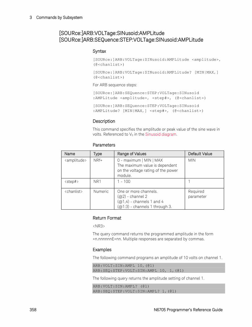
3 Commands by Subsystem
358 N6705 Programmer’s Reference Guide
[SOURce:]ARB:VOLTage:SINusoid:AMPLitude [SOURce:]ARB:SEQuence:STEP:VOLTage:SINusoid:AMPLitude
Syntax
[SOURce:]ARB:VOLTage:SINusoid:AMPLitude <amplitude>, (@<chanlist>)
[SOURce:]ARB:VOLTage:SINusoid:AMPLitude? [MIN|MAX,] (@<chanlist>)
For ARB sequence steps:
[SOURce:]ARB:SEQuence:STEP:VOLTage:SINusoid :AMPLitude <amplitude>, <step#>, (@<chanlist>)
[SOURce:]ARB:SEQuence:STEP:VOLTage:SINusoid :AMPLitude? [MIN|MAX,] <step#>, (@<chanlist>)
Description
This command specifies the amplitude or peak value of the sine wave in volts. Referenced to V0 in the Sinusoid diagram.
Parameters
Name Type Range of Values Default Value
<amplitude> NRf+ 0 - maximum | MIN | MAX The maximum value is dependent on the voltage rating of the power module.
MIN
<step#> NR1 1 - 100 1
<chanlist> Numeric One or more channels. (@2) - channel 2 (@1,4) - channels 1 and 4 (@1:3) - channels 1 through 3.
Required parameter
Return Format
<NR3>
The query command returns the programmed amplitude in the form +n.nnnnnnE+nn. Multiple responses are separated by commas.
Examples
The following command programs an amplitude of 10 volts on channel 1.
ARB:VOLT:SIN:AMPL 10,(@1) ARB:SEQ:STEP:VOLT:SIN:AMPL 10, 1,(@1)
The following query returns the amplitude setting of channel 1.
ARB:VOLT:SIN:AMPL? (@1) ARB:SEQ:STEP:VOLT:SIN:AMPL? 1,(@1)
Commands by Subsystem 3
N6705 Programmer’s Reference Guide 359
Typical Response: +1.000000E+01
See Also
[SOURce:]ARB:VOLTage:SINusoid:OFFSet
[SOURce:]ARB:VOLTage:SINusoid:FREQuency
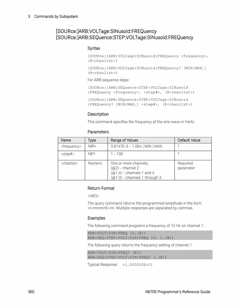
3 Commands by Subsystem
360 N6705 Programmer’s Reference Guide
[SOURce:]ARB:VOLTage:SINusoid:FREQuency [SOURce:]ARB:SEQuence:STEP:VOLTage:SINusoid:FREQuency
Syntax
[SOURce:]ARB:VOLTage:SINusoid:FREQuency <frequency>, (@<chanlist>)
[SOURce:]ARB:VOLTage:SINusoid:FREQuency? [MIN|MAX,] (@<chanlist>)
For ARB sequence steps:
[SOURce:]ARB:SEQuence:STEP:VOLTage:SINusoid :FREQuency <frequency>, <step#>, (@<chanlist>)
[SOURce:]ARB:SEQuence:STEP:VOLTage:SINusoid :FREQuency? [MIN|MAX,] <step#>, (@<chanlist>)
Description
This command specifies the frequency of the sine wave in Hertz.
Parameters
Name Type Range of Values Default Value
<frequency> NRf+ 3.8147E-5 - 1.0E4 | MIN | MAX 1
<step#> NR1 1 - 100 1
<chanlist> Numeric One or more channels. (@2) - channel 2 (@1,4) - channels 1 and 4 (@1:3) - channels 1 through 3.
Required parameter
Return Format
<NR3>
The query command returns the programmed amplitude in the form +n.nnnnnnE+nn. Multiple responses are separated by commas.
Examples
The following command programs a frequency of 10 Hz on channel 1.
ARB:VOLT:SIN:FREQ 10,(@1) ARB:SEQ:STEP:VOLT:SIN:FREQ 10, 1,(@1)
The following query returns the frequency setting of channel 1.
ARB:VOLT:SIN:FREQ? (@1) ARB:SEQ:STEP:VOLT:SIN:FREQ? 1,(@1)
Typical Response: +1.000000E+01
Commands by Subsystem 3
N6705 Programmer’s Reference Guide 361
See Also
[SOURce:]ARB:VOLTage:SINusoid:AMPLitude
[SOURce:]ARB:VOLTage:SINusoid:OFFSet
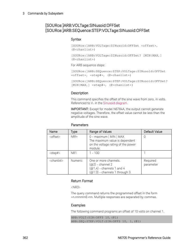
3 Commands by Subsystem
362 N6705 Programmer’s Reference Guide
[SOURce:]ARB:VOLTage:SINusoid:OFFSet [SOURce:]ARB:SEQuence:STEP:VOLTage:SINusoid:OFFSet
Syntax
[SOURce:]ARB:VOLTage:SINusoid:OFFSet <offset>, (@<chanlist>)
[SOURce:]ARB:VOLTage:SINusoid:OFFSet? [MIN|MAX,] (@<chanlist>)
For ARB sequence steps:
[SOURce:]ARB:SEQuence:STEP:VOLTage:SINusoid:OFFSet <offset>, <step#>, (@<chanlist>)
[SOURce:]ARB:SEQuence:STEP:VOLTage:SINusoid:OFFSet? [MIN|MAX,] <step#>, (@<chanlist>)
Description
This command specifies the offset of the sine wave from zero, in volts. Referenced to V1 in the Sinusoid diagram.
IMPORTANT: Except for model N6784A, the output cannot generate negative voltages. Therefore, the offset value cannot be less than the amplitude of the sine wave.
Parameters
Name Type Range of Values Default Value
<offset> NRf+ 0 - maximum | MIN | MAX The maximum value is dependent on the voltage rating of the power module.
0
<step#> NR1 1 - 100 1
<chanlist> Numeric One or more channels. (@2) - channel 2 (@1,4) - channels 1 and 4 (@1:3) - channels 1 through 3.
Required parameter
Return Format
<NR3>
The query command returns the programmed offset in the form +n.nnnnnnE+nn. Multiple responses are separated by commas.
Examples
The following command programs an offset of 10 volts on channel 1.
ARB:VOLT:SIN:OFFS 10,(@1) ARB:SEQ:STEP:VOLT:SIN:OFFS 10, 1,(@1)
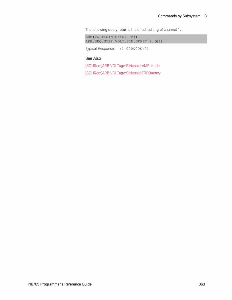
Commands by Subsystem 3
N6705 Programmer’s Reference Guide 363
The following query returns the offset setting of channel 1.
ARB:VOLT:SIN:OFFS? (@1) ARB:SEQ:STEP:VOLT:SIN:OFFS? 1,(@1)
Typical Response: +1.000000E+01
See Also
[SOURce:]ARB:VOLTage:SINusoid:AMPLitude
[SOURce:]ARB:VOLTage:SINusoid:FREQuency
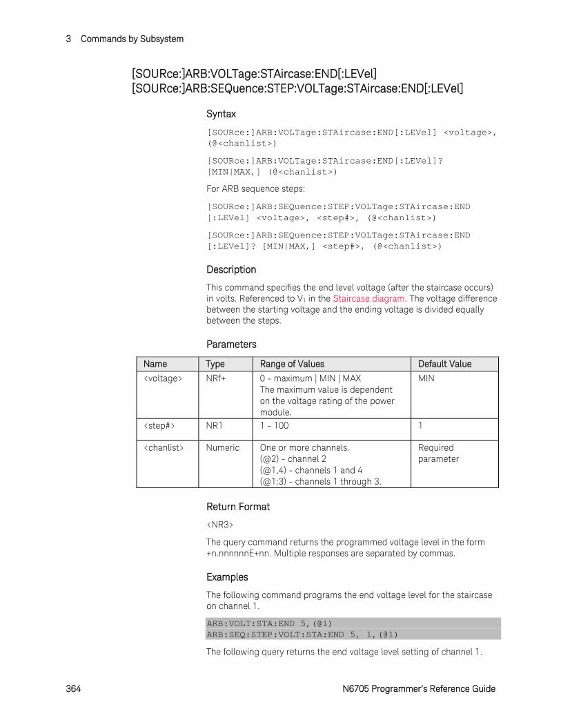
3 Commands by Subsystem
364 N6705 Programmer’s Reference Guide
[SOURce:]ARB:VOLTage:STAircase:END[:LEVel] [SOURce:]ARB:SEQuence:STEP:VOLTage:STAircase:END[:LEVel]
Syntax
[SOURce:]ARB:VOLTage:STAircase:END[:LEVel] <voltage>, (@<chanlist>)
[SOURce:]ARB:VOLTage:STAircase:END[:LEVel]? [MIN|MAX,] (@<chanlist>)
For ARB sequence steps:
[SOURce:]ARB:SEQuence:STEP:VOLTage:STAircase:END [:LEVel] <voltage>, <step#>, (@<chanlist>)
[SOURce:]ARB:SEQuence:STEP:VOLTage:STAircase:END [:LEVel]? [MIN|MAX,] <step#>, (@<chanlist>)
Description
This command specifies the end level voltage (after the staircase occurs) in volts. Referenced to V1 in the Staircase diagram. The voltage difference between the starting voltage and the ending voltage is divided equally between the steps.
Parameters
Name Type Range of Values Default Value
<voltage> NRf+ 0 - maximum | MIN | MAX The maximum value is dependent on the voltage rating of the power module.
MIN
<step#> NR1 1 - 100 1
<chanlist> Numeric One or more channels. (@2) - channel 2 (@1,4) - channels 1 and 4 (@1:3) - channels 1 through 3.
Required parameter
Return Format
<NR3>
The query command returns the programmed voltage level in the form +n.nnnnnnE+nn. Multiple responses are separated by commas.
Examples
The following command programs the end voltage level for the staircase on channel 1.
ARB:VOLT:STA:END 5,(@1) ARB:SEQ:STEP:VOLT:STA:END 5, 1,(@1)
The following query returns the end voltage level setting of channel 1.
Commands by Subsystem 3
N6705 Programmer’s Reference Guide 365
ARB:VOLT:STA:END? (@1) ARB:SEQ:STEP:VOLT:STA:END? 1,(@1)
Typical Response: +5.000000E+00
See Also
[SOURce:]ARB:VOLTage:STAircase:STARt[:LEVel]
[SOURce:]ARB:VOLTage:STAircase:END:TIMe
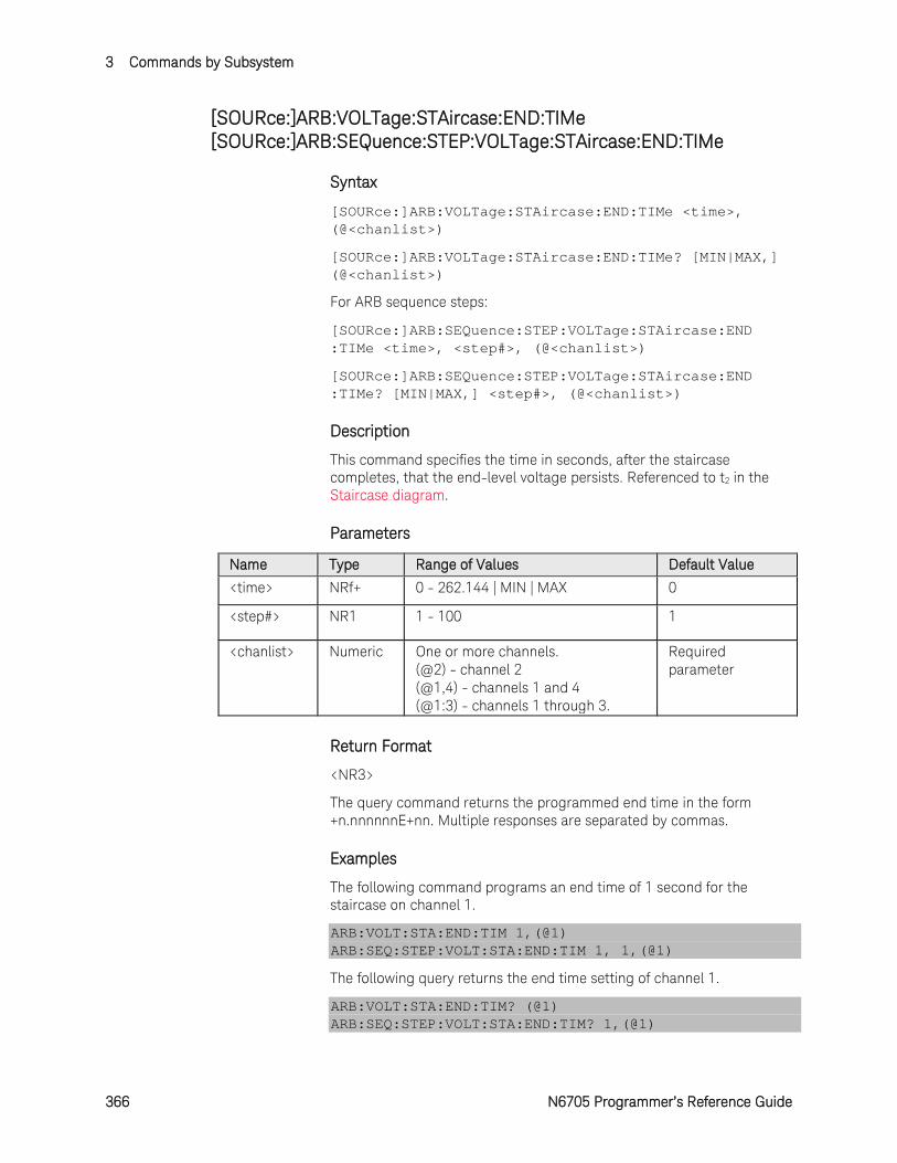
3 Commands by Subsystem
366 N6705 Programmer’s Reference Guide
[SOURce:]ARB:VOLTage:STAircase:END:TIMe [SOURce:]ARB:SEQuence:STEP:VOLTage:STAircase:END:TIMe
Syntax
[SOURce:]ARB:VOLTage:STAircase:END:TIMe <time>, (@<chanlist>)
[SOURce:]ARB:VOLTage:STAircase:END:TIMe? [MIN|MAX,] (@<chanlist>)
For ARB sequence steps:
[SOURce:]ARB:SEQuence:STEP:VOLTage:STAircase:END :TIMe <time>, <step#>, (@<chanlist>)
[SOURce:]ARB:SEQuence:STEP:VOLTage:STAircase:END :TIMe? [MIN|MAX,] <step#>, (@<chanlist>)
Description
This command specifies the time in seconds, after the staircase completes, that the end-level voltage persists. Referenced to t2 in the Staircase diagram.
Parameters
Name Type Range of Values Default Value
<time> NRf+ 0 - 262.144 | MIN | MAX 0
<step#> NR1 1 - 100 1
<chanlist> Numeric One or more channels. (@2) - channel 2 (@1,4) - channels 1 and 4 (@1:3) - channels 1 through 3.
Required parameter
Return Format
<NR3>
The query command returns the programmed end time in the form +n.nnnnnnE+nn. Multiple responses are separated by commas.
Examples
The following command programs an end time of 1 second for the staircase on channel 1.
ARB:VOLT:STA:END:TIM 1,(@1) ARB:SEQ:STEP:VOLT:STA:END:TIM 1, 1,(@1)
The following query returns the end time setting of channel 1.
ARB:VOLT:STA:END:TIM? (@1) ARB:SEQ:STEP:VOLT:STA:END:TIM? 1,(@1)
Commands by Subsystem 3
N6705 Programmer’s Reference Guide 367
Typical Response: +1.000000E+00
See Also
[SOURce:]ARB:VOLTage:STAircase:END[:LEVel]
[SOURce:]ARB:VOLTage:STAircase:STARt:TIMe
[SOURce:]ARB:VOLTage:STAircase:TIMe
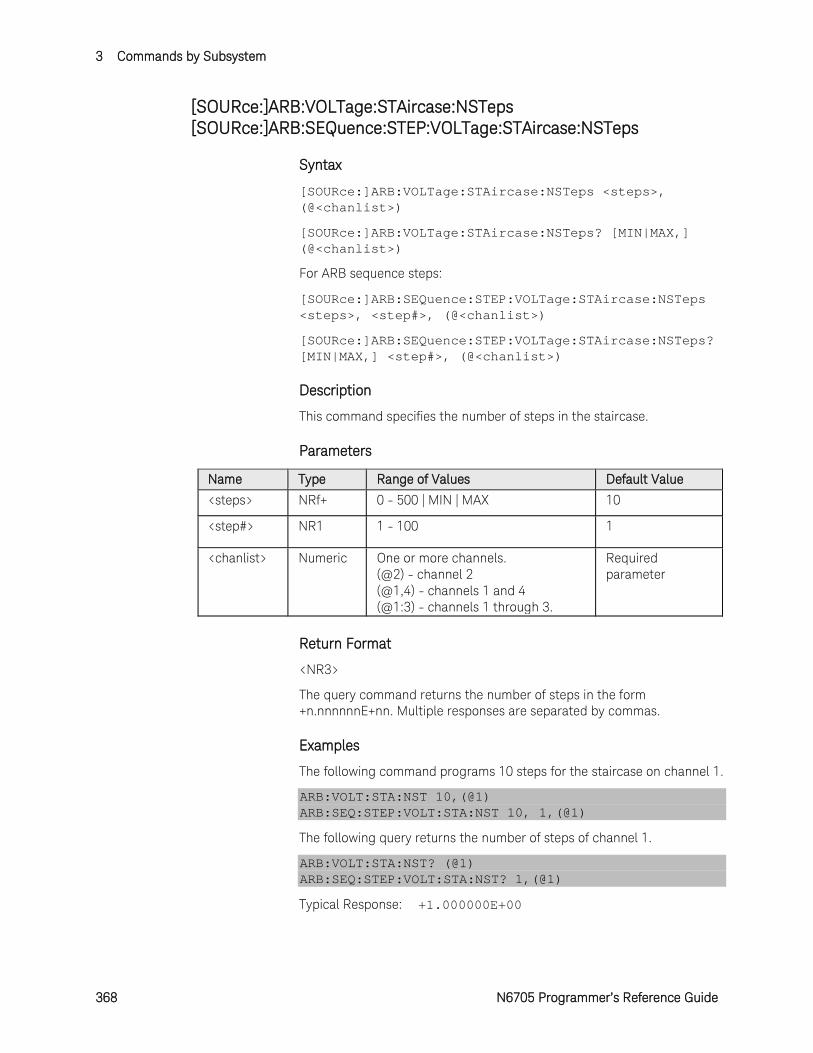
3 Commands by Subsystem
368 N6705 Programmer’s Reference Guide
[SOURce:]ARB:VOLTage:STAircase:NSTeps [SOURce:]ARB:SEQuence:STEP:VOLTage:STAircase:NSTeps
Syntax
[SOURce:]ARB:VOLTage:STAircase:NSTeps <steps>, (@<chanlist>)
[SOURce:]ARB:VOLTage:STAircase:NSTeps? [MIN|MAX,] (@<chanlist>)
For ARB sequence steps:
[SOURce:]ARB:SEQuence:STEP:VOLTage:STAircase:NSTeps <steps>, <step#>, (@<chanlist>)
[SOURce:]ARB:SEQuence:STEP:VOLTage:STAircase:NSTeps? [MIN|MAX,] <step#>, (@<chanlist>)
Description
This command specifies the number of steps in the staircase.
Parameters
Name Type Range of Values Default Value
<steps> NRf+ 0 - 500 | MIN | MAX 10
<step#> NR1 1 - 100 1
<chanlist> Numeric One or more channels. (@2) - channel 2 (@1,4) - channels 1 and 4 (@1:3) - channels 1 through 3.
Required parameter
Return Format
<NR3>
The query command returns the number of steps in the form +n.nnnnnnE+nn. Multiple responses are separated by commas.
Examples
The following command programs 10 steps for the staircase on channel 1.
ARB:VOLT:STA:NST 10,(@1) ARB:SEQ:STEP:VOLT:STA:NST 10, 1,(@1)
The following query returns the number of steps of channel 1.
ARB:VOLT:STA:NST? (@1) ARB:SEQ:STEP:VOLT:STA:NST? 1,(@1)
Typical Response: +1.000000E+00
Commands by Subsystem 3
N6705 Programmer’s Reference Guide 369
[SOURce:]ARB:VOLTage:STAircase:STARt[:LEVel] [SOURce:]ARB:SEQuence:STEP:VOLTage:STAircase:STARt[:LEVel]
Syntax
[SOURce:]ARB:VOLTage:STAircase:STARt[:LEVel] <voltage>, (@<chanlist>)
[SOURce:]ARB:VOLTage:STAircase:STARt[:LEVel]? [MIN|MAX,] (@<chanlist>)
For ARB sequence steps:
[SOURce:]ARB:SEQuence:STEP:VOLTage:STAircase:STARt [:LEVel] <voltage>, <step#>, (@<chanlist>)
[SOURce:]ARB:SEQuence:STEP:VOLTage:STAircase:STARt [:LEVel]? [MIN|MAX,] <step#>, (@<chanlist>)
Description
This command specifies the initial voltage (before the staircase occurs) in volts. Referenced to V0 in the Staircase diagram.
Parameters
Name Type Range of Values Default Value
<voltage> NRf+ 0 - maximum | MIN | MAX The maximum value is dependent on the voltage rating of the power module.
MIN
<step#> NR1 1 - 100 1
<chanlist> Numeric One or more channels. (@2) - channel 2 (@1,4) - channels 1 and 4 (@1:3) - channels 1 through 3.
Required parameter
Return Format
<NR3>
The query command returns the programmed voltage level in the form +n.nnnnnnE+nn. Multiple responses are separated by commas.
Examples
The following command programs an initial voltage level for the staircase on channel 1.
ARB:VOLT:STA:STAR 1,(@1) ARB:SEQ:STEP:VOLT:STA:STAR 1, 1,(@1)
The following query returns the initial voltage staircase setting of channel 1.
3 Commands by Subsystem
370 N6705 Programmer’s Reference Guide
ARB:VOLT:STA:STAR? (@1) ARB:SEQ:STEP:VOLT:STA:STAR? 1,(@1)
Typical Response: +1.000000E+00
See Also
[SOURce:]ARB:VOLTage:STAircase:STARt:TIMe
[SOURce:]ARB:VOLTage:STAircase:END[:LEVel]
Commands by Subsystem 3
N6705 Programmer’s Reference Guide 371
[SOURce:]ARB:VOLTage:STAircase:STARt:TIMe [SOURce:]ARB:SEQuence:STEP:VOLTage:STAircase:STARt:TIMe
Syntax
[SOURce:]ARB:VOLTage:STAircase:STARt:TIMe <time>, (@<chanlist>)
[SOURce:]ARB:VOLTage:STAircase:STARt:TIMe? [MIN|MAX,] (@<chanlist>)
For ARB sequence steps:
[SOURce:]ARB:SEQuence:STEP:VOLTage:STEP:STARt:TIMe <time>, <step#>, (@<chanlist>)
[SOURce:]ARB:SEQuence:STEP:VOLTage:STEP:STARt:TIMe? [MIN|MAX,] <step#>, (@<chanlist>)
Description
This command specifies the delay in seconds after the trigger is received, but before the staircase occurs. Referenced to t0 in the Staircase diagram.
Parameters
Name Type Range of Values Default Value
<time> NRf+ 0 - 262.144 | MIN | MAX 0
<step#> NR1 1 - 100 1
<chanlist> Numeric One or more channels. (@2) - channel 2 (@1,4) - channels 1 and 4 (@1:3) - channels 1 through 3.
Required parameter
Return Format
<NR3>
The query command returns the programmed start time in the form +n.nnnnnnE+nn. Multiple responses are separated by commas.
Examples
The following command programs a start time of 1 second for the staircase on channel 1.
ARB:VOLT:STA:STAR:TIM 1,(@1) ARB:SEQ:STEP:VOLT:STA:STAR:TIM 1, 1,(@1)
The following query returns the start time setting of channel 1.
ARB:VOLT:STA:STAR:TIM? (@1) ARB:SEQ:STEP:VOLT:STA:STAR:TIM? 1,(@1)
Typical Response: +1.000000E+00
3 Commands by Subsystem
372 N6705 Programmer’s Reference Guide
See Also
[SOURce:]ARB:VOLTage:STAircase:STARt[:LEVel]
[SOURce:]ARB:VOLTage:STAircase:END:TIMe
[SOURce:]ARB:VOLTage:STAircase:TIMe
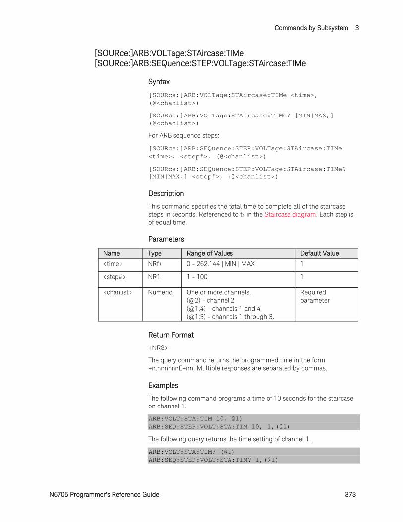
Commands by Subsystem 3
N6705 Programmer’s Reference Guide 373
[SOURce:]ARB:VOLTage:STAircase:TIMe [SOURce:]ARB:SEQuence:STEP:VOLTage:STAircase:TIMe
Syntax
[SOURce:]ARB:VOLTage:STAircase:TIMe <time>, (@<chanlist>)
[SOURce:]ARB:VOLTage:STAircase:TIMe? [MIN|MAX,] (@<chanlist>)
For ARB sequence steps:
[SOURce:]ARB:SEQuence:STEP:VOLTage:STAircase:TIMe <time>, <step#>, (@<chanlist>)
[SOURce:]ARB:SEQuence:STEP:VOLTage:STAircase:TIMe? [MIN|MAX,] <step#>, (@<chanlist>)
Description
This command specifies the total time to complete all of the staircase steps in seconds. Referenced to t1 in the Staircase diagram. Each step is of equal time.
Parameters
Name Type Range of Values Default Value
<time> NRf+ 0 - 262.144 | MIN | MAX 1
<step#> NR1 1 - 100 1
<chanlist> Numeric One or more channels. (@2) - channel 2 (@1,4) - channels 1 and 4 (@1:3) - channels 1 through 3.
Required parameter
Return Format
<NR3>
The query command returns the programmed time in the form +n.nnnnnnE+nn. Multiple responses are separated by commas.
Examples
The following command programs a time of 10 seconds for the staircase on channel 1.
ARB:VOLT:STA:TIM 10,(@1) ARB:SEQ:STEP:VOLT:STA:TIM 10, 1,(@1)
The following query returns the time setting of channel 1.
ARB:VOLT:STA:TIM? (@1) ARB:SEQ:STEP:VOLT:STA:TIM? 1,(@1)
3 Commands by Subsystem
374 N6705 Programmer’s Reference Guide
Typical Response: +1.000000E+01
See Also
[SOURce:]ARB:VOLTage:STAircase:STARt:TIMe
[SOURce:]ARB:VOLTage:STAircase:END:TIMe
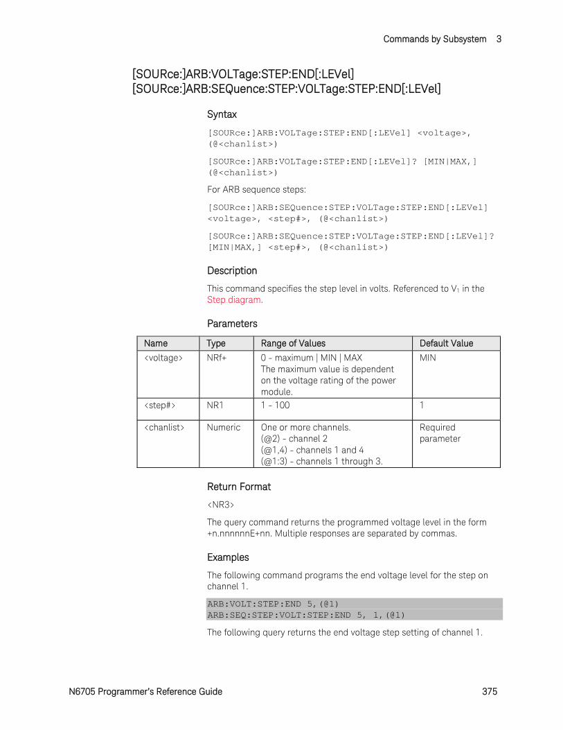
Commands by Subsystem 3
N6705 Programmer’s Reference Guide 375
[SOURce:]ARB:VOLTage:STEP:END[:LEVel] [SOURce:]ARB:SEQuence:STEP:VOLTage:STEP:END[:LEVel]
Syntax
[SOURce:]ARB:VOLTage:STEP:END[:LEVel] <voltage>, (@<chanlist>)
[SOURce:]ARB:VOLTage:STEP:END[:LEVel]? [MIN|MAX,] (@<chanlist>)
For ARB sequence steps:
[SOURce:]ARB:SEQuence:STEP:VOLTage:STEP:END[:LEVel] <voltage>, <step#>, (@<chanlist>)
[SOURce:]ARB:SEQuence:STEP:VOLTage:STEP:END[:LEVel]? [MIN|MAX,] <step#>, (@<chanlist>)
Description
This command specifies the step level in volts. Referenced to V1 in the Step diagram.
Parameters
Name Type Range of Values Default Value
<voltage> NRf+ 0 - maximum | MIN | MAX The maximum value is dependent on the voltage rating of the power module.
MIN
<step#> NR1 1 - 100 1
<chanlist> Numeric One or more channels. (@2) - channel 2 (@1,4) - channels 1 and 4 (@1:3) - channels 1 through 3.
Required parameter
Return Format
<NR3>
The query command returns the programmed voltage level in the form +n.nnnnnnE+nn. Multiple responses are separated by commas.
Examples
The following command programs the end voltage level for the step on channel 1.
ARB:VOLT:STEP:END 5,(@1) ARB:SEQ:STEP:VOLT:STEP:END 5, 1,(@1)
The following query returns the end voltage step setting of channel 1.

3 Commands by Subsystem
376 N6705 Programmer’s Reference Guide
ARB:VOLT:STEP:END? (@1) ARB:SEQ:STEP:VOLT:STEP:END? 1,(@1)
Typical Response: +5.000000E+00
See Also
[SOURce:]ARB:VOLTage:STEP:STARt[:LEVel]
[SOURce:]ARB:VOLTage:STEP:STARt:TIMe

Commands by Subsystem 3
N6705 Programmer’s Reference Guide 377
[SOURce:]ARB:VOLTage:STEP:STARt[:LEVel] [SOURce:]ARB:SEQuence:STEP:VOLTage:STEP:STARt[:LEVel]
Syntax
[SOURce:]ARB:VOLTage:STEP:STARt[:LEVel] <voltage>, (@<chanlist>)
[SOURce:]ARB:VOLTage:STEP:STARt[:LEVel]? [MIN|MAX,] (@<chanlist>)
For ARB sequence steps:
[SOURce:]ARB:SEQuence:STEP:VOLTage:STEP:STARt [:LEVel] <voltage>, <step#>, (@<chanlist>)
[SOURce:]ARB:SEQuence:STEP:VOLTage:STEP:STARt [:LEVel]? [MIN|MAX,] <step#>, (@<chanlist>)
Description
This command specifies the initial voltage level in volts. Referenced to V0 in the Step diagram.
Parameters
Name Type Range of Values Default Value
<voltage> NRf+ 0 - maximum | MIN | MAX The maximum value is dependent on the voltage rating of the power module.
MIN
<step#> NR1 1 - 100 1
<chanlist> Numeric One or more channels. (@2) - channel 2 (@1,4) - channels 1 and 4 (@1:3) - channels 1 through 3.
Required parameter
Return Format
<NR3>
The query command returns the programmed voltage level in the form +n.nnnnnnE+nn. Multiple responses are separated by commas.
Examples
The following command programs an initial voltage level for the step on channel 1.
ARB:VOLT:STEP:STAR 1,(@1) ARB:SEQ:STEP:VOLT:STEP:STAR 1, 1,(@1)
The following query returns the initial voltage step setting of channel 1.
3 Commands by Subsystem
378 N6705 Programmer’s Reference Guide
ARB:VOLT:STEP:STAR? (@1) ARB:SEQ:STEP:VOLT:STEP:STAR? 1,(@1)
Typical Response: +1.000000E+00
See Also
[SOURce:]ARB:VOLTage:STEP:STARt:TIMe
[SOURce:]ARB:VOLTage:STEP:END[:LEVel]

Commands by Subsystem 3
N6705 Programmer’s Reference Guide 379
[SOURce:]ARB:VOLTage:STEP:STARt:TIMe [SOURce:]ARB:SEQuence:STEP:VOLTage:STEP:STARt:TIMe
Syntax
[SOURce:]ARB:VOLTage:STEP:STARt:TIMe <time>, (@<chanlist>)
[SOURce:]ARB:VOLTage:STEP:STARt:TIMe? [MIN|MAX,] (@<chanlist>)
For ARB sequence steps:
[SOURce:]ARB:SEQuence:STEP:VOLTage:STEP:STARt:TIMe <time>, <step#>, (@<chanlist>)
[SOURce:]ARB:SEQuence:STEP:VOLTage:STEP:STARt:TIMe? [MIN|MAX,] <step#>, (@<chanlist>)
Description
This command specifies the delay in seconds after the trigger is received, but before the step occurs. Referenced to t0 in the Step diagram.
Parameters
Name Type Range of Values Default Value
<time> NRf+ 0 - 262.144 | MIN | MAX 0
<step#> NR1 1 - 100 1
<chanlist> Numeric One or more channels. (@2) - channel 2 (@1,4) - channels 1 and 4 (@1:3) - channels 1 through 3.
Required parameter
Return Format
<NR3>
The query command returns the programmed start time in the form +n.nnnnnnE+nn. Multiple responses are separated by commas.
Examples
The following command programs a start time of 1 second for the step on channel 1.
ARB:VOLT:STEP:STAR:TIM 1,(@1) ARB:SEQ:STEP:VOLT:STEP:STAR:TIM 1, 1,(@1)
The following query returns the start time setting of channel 1.
ARB:VOLT:STEP:STAR:TIM? (@1) ARB:SEQ:STEP:VOLT:STEP:STAR:TIM? 1,(@1)
Typical Response: +1.000000E+00
3 Commands by Subsystem
380 N6705 Programmer’s Reference Guide
See Also
[SOURce:]ARB:VOLTage:STEP:STARt[:LEVel]
[SOURce:]ARB:VOLTage:STEP:END[:LEVel]

Commands by Subsystem 3
N6705 Programmer’s Reference Guide 381
[SOURce:]ARB:VOLTage:TRAPezoid:END:TIMe [SOURce:]ARB:SEQuence:STEP:VOLTage:TRAPezoid:END:TIMe
Syntax
[SOURce:]ARB:VOLTage:TRAPezoid:END:TIMe <time>, (@<chanlist>)
[SOURce:]ARB:VOLTage:TRAPezoid:END:TIMe? [MIN|MAX,] (@<chanlist>)
For ARB sequence steps:
[SOURce:]ARB:SEQuence:STEP:VOLTage:TRAPezoid:END :TIMe <time>, <step#>, (@<chanlist>)
[SOURce:]ARB:SEQuence:STEP:VOLTage:TRAPezoid:END :TIMe? [MIN|MAX,] <step#>, (@<chanlist>)
Description
This command specifies the time in seconds, after the trapezoid completes, that the start-level voltage persists. Referenced to t4 in the Trapezoid diagram.
Parameters
Name Type Range of Values Default Value
<time> NRf+ 0 - 262.144 | MIN | MAX 0
<step#> NR1 1 - 100 1
<chanlist> Numeric One or more channels. (@2) - channel 2 (@1,4) - channels 1 and 4 (@1:3) - channels 1 through 3.
Required parameter
Return Format
<NR3>
The query command returns the programmed end time in the form +n.nnnnnnE+nn. Multiple responses are separated by commas.
Examples
The following command programs an end time of 1 second after the trapezoid on channel 1.
ARB:VOLT:TRAP:END:TIM 1,(@1) ARB:SEQ:STEP:VOLT:TRAP:END:TIM 1, 1,(@1)
The following query returns the end time setting of channel 1.
ARB:VOLT:TRAP:END:TIM? (@1) ARB:SEQ:STEP:VOLT:TRAP:END:TIM? 1,(@1)
3 Commands by Subsystem
382 N6705 Programmer’s Reference Guide
Typical Response: +1.000000E+00
See Also
[SOURce:]ARB:VOLTage:TRAPezoid:STARt:TIMe
[SOURce:]ARB:VOLTage:TRAPezoid:STARt[:LEVel]
[SOURce:]ARB:VOLTage:TRAPezoid:TOP:TIMe

Commands by Subsystem 3
N6705 Programmer’s Reference Guide 383
[SOURce:]ARB:VOLTage:TRAPezoid:FTIMe [SOURce:]ARB:SEQuence:STEP:VOLTage:TRAPezoid:FTIMe
Syntax
[SOURce:]ARB:VOLTage:TRAPezoid:FTIMe <time>, (@<chanlist>)
[SOURce:]ARB:VOLTage:TRAPezoid:FTIMe? [MIN|MAX,] (@<chanlist>)
For ARB sequence steps:
[SOURce:]ARB:SEQuence:STEP:VOLTage:TRAPezoid:FTIMe <time>, <step#>, (@<chanlist>)
[SOURce:]ARB:SEQuence:STEP:VOLTage:TRAPezoid:FTIMe? [MIN|MAX,] <step#>, (@<chanlist>)
Description
This command specifies the fall time of the trapezoid in seconds. Referenced to t3 in the Trapezoid diagram.
Parameters
Name Type Range of Values Default Value
<time> NRf+ 0 - 262.144 | MIN | MAX 1
<step#> NR1 1 - 100 1
<chanlist> Numeric One or more channels. (@2) - channel 2 (@1,4) - channels 1 and 4 (@1:3) - channels 1 through 3.
Required parameter
Return Format
<NR3>
The query command returns the programmed fall time in the form +n.nnnnnnE+nn. Multiple responses are separated by commas.
Examples
The following command programs a fall time of 10 seconds for the trapezoid on channel 1.
ARB:VOLT:TRAP:FTIM 10,(@1) ARB:SEQ:STEP:VOLT:TRAP:FTIM 10, 1,(@1)
The following query returns the fall time setting of channel 1.
ARB:VOLT:TRAP:FTIM? (@1) ARB:SEQ:STEP:VOLT:TRAP:FTIM? 1,(@1)
Typical Response: +1.000000E+01
3 Commands by Subsystem
384 N6705 Programmer’s Reference Guide
See Also
[SOURce:]ARB:VOLTage:TRAPezoid:STARt:TIMe
[SOURce:]ARB:VOLTage:TRAPezoid:END:TIMe
[SOURce:]ARB:VOLTage:TRAPezoid:TOP:TIMe

Commands by Subsystem 3
N6705 Programmer’s Reference Guide 385
[SOURce:]ARB:VOLTage:TRAPezoid:RTIMe [SOURce:]ARB:SEQuence:STEP:VOLTage:TRAPezoid:RTIMe
Syntax
[SOURce:]ARB:VOLTage:TRAPezoid:RTIMe <time>, (@<chanlist>)
[SOURce:]ARB:VOLTage:TRAPezoid:RTIMe? [MIN|MAX,] (@<chanlist>)
For ARB sequence steps:
[SOURce:]ARB:SEQuence:STEP:VOLTage:TRAPezoid:RTIMe <time>, <step#>, (@<chanlist>)
[SOURce:]ARB:SEQuence:STEP:VOLTage:TRAPezoid:RTIMe? [MIN|MAX,] <step#>, (@<chanlist>)
Description
This command specifies the rise time of the trapezoid in seconds. Referenced to t1 in the Trapezoid diagram.
Parameters
Name Type Range of Values Default Value
<time> NRf+ 0 - 262.144 | MIN | MAX 1
<step#> NR1 1 - 100 1
<chanlist> Numeric One or more channels. (@2) - channel 2 (@1,4) - channels 1 and 4 (@1:3) - channels 1 through 3.
Required parameter
Return Format
<NR3>
The query command returns the programmed rise time in the form +n.nnnnnnE+nn. Multiple responses are separated by commas.
Examples
The following command programs a rise time of 10 seconds for the trapezoid on channel 1.
ARB:VOLT:TRAP:RTIM 10,(@1) ARB:SEQ:STEP:VOLT:TRAP:RTIM 10, 1,(@1)
The following query returns the rise time setting of channel 1.
ARB:VOLT:TRAP:RTIM? (@1) ARB:SEQ:STEP:VOLT:TRAP:RTIM? 1,(@1)
Typical Response: +1.000000E+01
3 Commands by Subsystem
386 N6705 Programmer’s Reference Guide
See Also
[SOURce:]ARB:VOLTage:TRAPezoid:STARt:TIMe
[SOURce:]ARB:VOLTage:TRAPezoid:END:TIMe
[SOURce:]ARB:VOLTage:TRAPezoid:TOP:TIMe
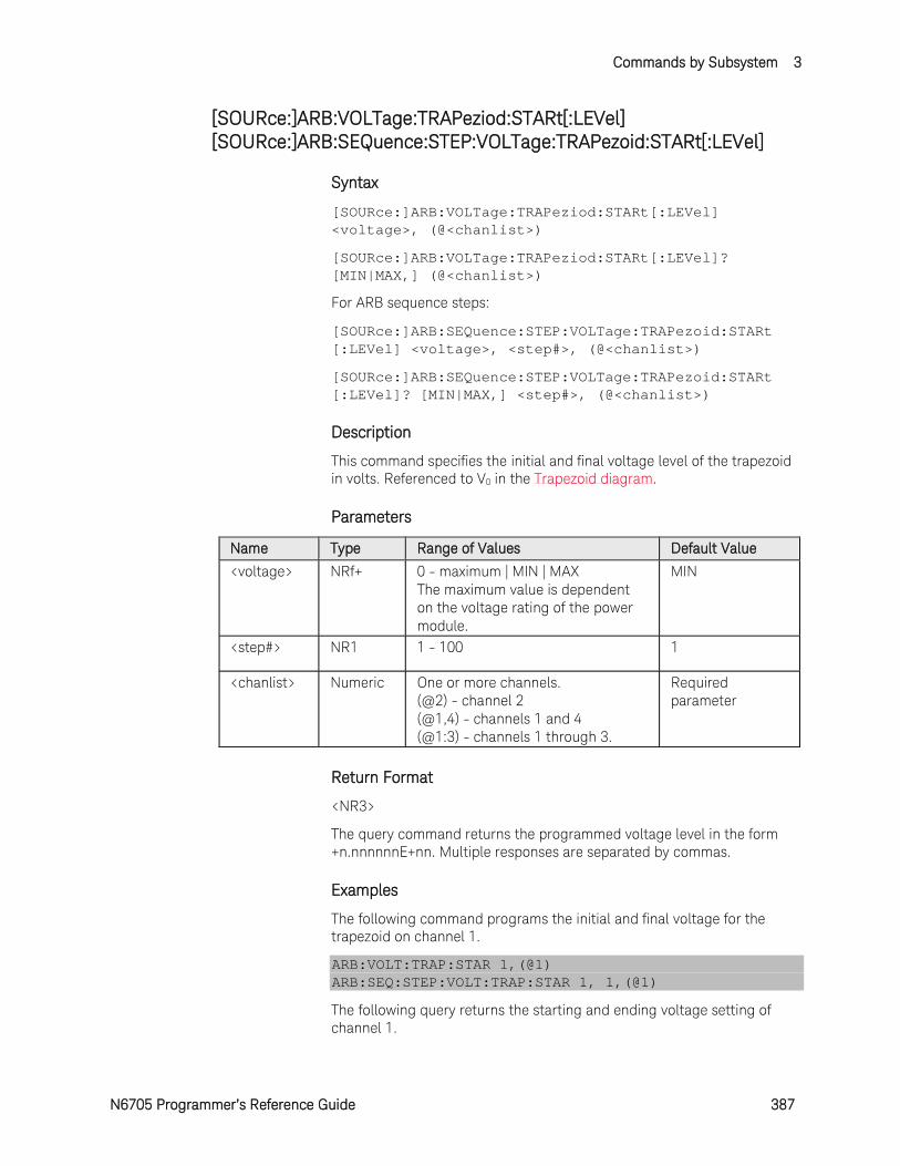
Commands by Subsystem 3
N6705 Programmer’s Reference Guide 387
[SOURce:]ARB:VOLTage:TRAPeziod:STARt[:LEVel] [SOURce:]ARB:SEQuence:STEP:VOLTage:TRAPezoid:STARt[:LEVel]
Syntax
[SOURce:]ARB:VOLTage:TRAPeziod:STARt[:LEVel] <voltage>, (@<chanlist>)
[SOURce:]ARB:VOLTage:TRAPeziod:STARt[:LEVel]? [MIN|MAX,] (@<chanlist>)
For ARB sequence steps:
[SOURce:]ARB:SEQuence:STEP:VOLTage:TRAPezoid:STARt [:LEVel] <voltage>, <step#>, (@<chanlist>)
[SOURce:]ARB:SEQuence:STEP:VOLTage:TRAPezoid:STARt [:LEVel]? [MIN|MAX,] <step#>, (@<chanlist>)
Description
This command specifies the initial and final voltage level of the trapezoid in volts. Referenced to V0 in the Trapezoid diagram.
Parameters
Name Type Range of Values Default Value
<voltage> NRf+ 0 - maximum | MIN | MAX The maximum value is dependent on the voltage rating of the power module.
MIN
<step#> NR1 1 - 100 1
<chanlist> Numeric One or more channels. (@2) - channel 2 (@1,4) - channels 1 and 4 (@1:3) - channels 1 through 3.
Required parameter
Return Format
<NR3>
The query command returns the programmed voltage level in the form +n.nnnnnnE+nn. Multiple responses are separated by commas.
Examples
The following command programs the initial and final voltage for the trapezoid on channel 1.
ARB:VOLT:TRAP:STAR 1,(@1) ARB:SEQ:STEP:VOLT:TRAP:STAR 1, 1,(@1)
The following query returns the starting and ending voltage setting of channel 1.

3 Commands by Subsystem
388 N6705 Programmer’s Reference Guide
ARB:VOLT:TRAP:STAR? (@1) ARB:SEQ:STEP:VOLT:TRAP:STAR? 1,(@1)
Typical Response: +1.000000E+00
See Also
[SOURce:]ARB:VOLTage:TRAPezoid:STARt:TIMe
[SOURce:]ARB:VOLTage:TRAPezoid:TOP[:LEVel]
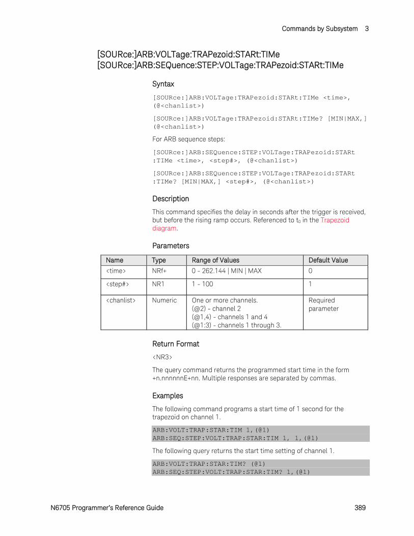
Commands by Subsystem 3
N6705 Programmer’s Reference Guide 389
[SOURce:]ARB:VOLTage:TRAPezoid:STARt:TIMe [SOURce:]ARB:SEQuence:STEP:VOLTage:TRAPezoid:STARt:TIMe
Syntax
[SOURce:]ARB:VOLTage:TRAPezoid:STARt:TIMe <time>, (@<chanlist>)
[SOURce:]ARB:VOLTage:TRAPezoid:STARt:TIMe? [MIN|MAX,] (@<chanlist>)
For ARB sequence steps:
[SOURce:]ARB:SEQuence:STEP:VOLTage:TRAPezoid:STARt :TIMe <time>, <step#>, (@<chanlist>)
[SOURce:]ARB:SEQuence:STEP:VOLTage:TRAPezoid:STARt :TIMe? [MIN|MAX,] <step#>, (@<chanlist>)
Description
This command specifies the delay in seconds after the trigger is received, but before the rising ramp occurs. Referenced to t0 in the Trapezoid diagram.
Parameters
Name Type Range of Values Default Value
<time> NRf+ 0 - 262.144 | MIN | MAX 0
<step#> NR1 1 - 100 1
<chanlist> Numeric One or more channels. (@2) - channel 2 (@1,4) - channels 1 and 4 (@1:3) - channels 1 through 3.
Required parameter
Return Format
<NR3>
The query command returns the programmed start time in the form +n.nnnnnnE+nn. Multiple responses are separated by commas.
Examples
The following command programs a start time of 1 second for the trapezoid on channel 1.
ARB:VOLT:TRAP:STAR:TIM 1,(@1) ARB:SEQ:STEP:VOLT:TRAP:STAR:TIM 1, 1,(@1)
The following query returns the start time setting of channel 1.
ARB:VOLT:TRAP:STAR:TIM? (@1) ARB:SEQ:STEP:VOLT:TRAP:STAR:TIM? 1,(@1)
3 Commands by Subsystem
390 N6705 Programmer’s Reference Guide
Typical Response: +1.000000E+00
See Also
[SOURce:]ARB:VOLTage:TRAPezoid:STARt[:LEVel]
[SOURce:]ARB:VOLTage:TRAPezoid:END:TIMe
[SOURce:]ARB:VOLTage:TRAPezoid:TOP:TIMe
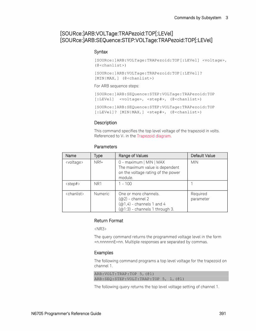
Commands by Subsystem 3
N6705 Programmer’s Reference Guide 391
[SOURce:]ARB:VOLTage:TRAPezoid:TOP[:LEVel] [SOURce:]ARB:SEQuence:STEP:VOLTage:TRAPezoid:TOP[:LEVel]
Syntax
[SOURce:]ARB:VOLTage:TRAPezoid:TOP[:LEVel] <voltage>, (@<chanlist>)
[SOURce:]ARB:VOLTage:TRAPezoid:TOP[:LEVel]? [MIN|MAX,] (@<chanlist>)
For ARB sequence steps:
[SOURce:]ARB:SEQuence:STEP:VOLTage:TRAPezoid:TOP [:LEVel] <voltage>, <step#>, (@<chanlist>)
[SOURce:]ARB:SEQuence:STEP:VOLTage:TRAPezoid:TOP [:LEVel]? [MIN|MAX,] <step#>, (@<chanlist>)
Description
This command specifies the top level voltage of the trapezoid in volts. Referenced to V1 in the Trapezoid diagram.
Parameters
Name Type Range of Values Default Value
<voltage> NRf+ 0 - maximum | MIN | MAX The maximum value is dependent on the voltage rating of the power module.
MIN
<step#> NR1 1 - 100 1
<chanlist> Numeric One or more channels. (@2) - channel 2 (@1,4) - channels 1 and 4 (@1:3) - channels 1 through 3.
Required parameter
Return Format
<NR3>
The query command returns the programmed voltage level in the form +n.nnnnnnE+nn. Multiple responses are separated by commas.
Examples
The following command programs a top level voltage for the trapezoid on channel 1.
ARB:VOLT:TRAP:TOP 5,(@1) ARB:SEQ:STEP:VOLT:TRAP:TOP 5, 1,(@1)
The following query returns the top level voltage setting of channel 1.

3 Commands by Subsystem
392 N6705 Programmer’s Reference Guide
ARB:VOLT:TRAP:TOP? (@1) ARB:SEQ:STEP:VOLT:TRAP:TOP? 1,(@1)
Typical Response: +5.000000E+00
See Also
[SOURce:]ARB:VOLTage:TRAPezoid:STARt[:LEVel]
[SOURce:]ARB:VOLTage:TRAPezoid:TOP:TIMe
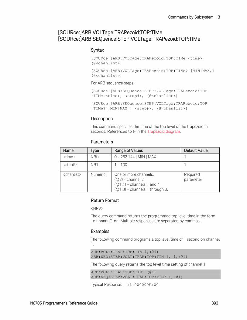
Commands by Subsystem 3
N6705 Programmer’s Reference Guide 393
[SOURce:]ARB:VOLTage:TRAPezoid:TOP:TIMe [SOURce:]ARB:SEQuence:STEP:VOLTage:TRAPezoid:TOP:TIMe
Syntax
[SOURce:]ARB:VOLTage:TRAPezoid:TOP:TIMe <time>, (@<chanlist>)
[SOURce:]ARB:VOLTage:TRAPezoid:TOP:TIMe? [MIN|MAX,] (@<chanlist>)
For ARB sequence steps:
[SOURce:]ARB:SEQuence:STEP:VOLTage:TRAPezoid:TOP :TIMe <time>, <step#>, (@<chanlist>)
[SOURce:]ARB:SEQuence:STEP:VOLTage:TRAPezoid:TOP :TIMe? [MIN|MAX,] <step#>, (@<chanlist>)
Description
This command specifies the time of the top level of the trapezoid in seconds. Referenced to t2 in the Trapezoid diagram.
Parameters
Name Type Range of Values Default Value
<time> NRf+ 0 - 262.144 | MIN | MAX 1
<step#> NR1 1 - 100 1
<chanlist> Numeric One or more channels. (@2) - channel 2 (@1,4) - channels 1 and 4 (@1:3) - channels 1 through 3.
Required parameter
Return Format
<NR3>
The query command returns the programmed top level time in the form +n.nnnnnnE+nn. Multiple responses are separated by commas.
Examples
The following command programs a top level time of 1 second on channel 1.
ARB:VOLT:TRAP:TOP:TIM 1,(@1) ARB:SEQ:STEP:VOLT:TRAP:TOP:TIM 1, 1,(@1)
The following query returns the top level time setting of channel 1.
ARB:VOLT:TRAP:TOP:TIM? (@1) ARB:SEQ:STEP:VOLT:TRAP:TOP:TIM? 1,(@1)
Typical Response: +1.000000E+00
3 Commands by Subsystem
394 N6705 Programmer’s Reference Guide
See Also
[SOURce:]ARB:VOLTage:TRAPezoid:RTIMe
[SOURce:]ARB:VOLTage:TRAPezoid:FTIMe
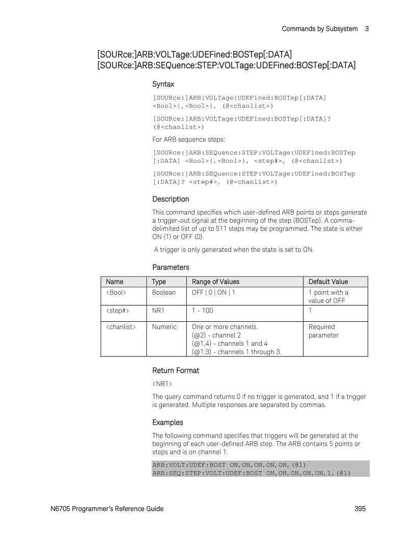
Commands by Subsystem 3
N6705 Programmer’s Reference Guide 395
[SOURce:]ARB:VOLTage:UDEFined:BOSTep[:DATA] [SOURce:]ARB:SEQuence:STEP:VOLTage:UDEFined:BOSTep[:DATA]
Syntax
[SOURce:]ARB:VOLTage:UDEFined:BOSTep[:DATA] <Bool>,<Bool>, (@<chanlist>)
[SOURce:]ARB:VOLTage:UDEFined:BOSTep[:DATA]? (@<chanlist>)
For ARB sequence steps:
[SOURce:]ARB:SEQuence:STEP:VOLTage:UDEFined:BOSTep [:DATA] <Bool>,<Bool>, <step#>, (@<chanlist>)
[SOURce:]ARB:SEQuence:STEP:VOLTage:UDEFined:BOSTep [:DATA]? <step#>, (@<chanlist>)
Description
This command specifies which user-defined ARB points or steps generate a trigger-out signal at the beginning of the step (BOSTep). A comma-delimited list of up to 511 steps may be programmed. The state is either ON (1) or OFF (0).
A trigger is only generated when the state is set to ON.
Parameters
Name Type Range of Values Default Value
<Bool> Boolean OFF | 0 | ON | 1 1 point with a value of OFF
<step#> NR1 1 - 100 1
<chanlist> Numeric One or more channels. (@2) - channel 2 (@1,4) - channels 1 and 4 (@1:3) - channels 1 through 3.
Required parameter
Return Format
<NR1>
The query command returns 0 if no trigger is generated, and 1 if a trigger is generated. Multiple responses are separated by commas.
Examples
The following command specifies that triggers will be generated at the beginning of each user-defined ARB step. The ARB contains 5 points or steps and is on channel 1.
ARB:VOLT:UDEF:BOST ON,ON,ON,ON,ON,(@1) ARB:SEQ:STEP:VOLT:UDEF:BOST ON,ON,ON,ON,ON,1,(@1)
3 Commands by Subsystem
396 N6705 Programmer’s Reference Guide
The following query returns the ARB step trigger settings of channel 1.
ARB:VOLT:UDEF:BOST? (@1) ARB:SEQ:STEP:VOLT:UDEF:BOST? 1,(@1)
Typical Response: 1,1,1,1,1
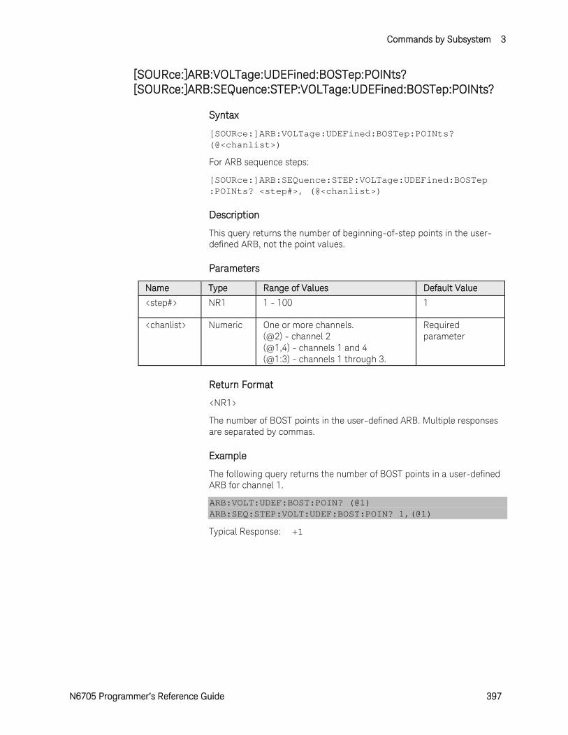
Commands by Subsystem 3
N6705 Programmer’s Reference Guide 397
[SOURce:]ARB:VOLTage:UDEFined:BOSTep:POINts? [SOURce:]ARB:SEQuence:STEP:VOLTage:UDEFined:BOSTep:POINts?
Syntax
[SOURce:]ARB:VOLTage:UDEFined:BOSTep:POINts? (@<chanlist>)
For ARB sequence steps:
[SOURce:]ARB:SEQuence:STEP:VOLTage:UDEFined:BOSTep :POINts? <step#>, (@<chanlist>)
Description
This query returns the number of beginning-of-step points in the user-defined ARB, not the point values.
Parameters
Name Type Range of Values Default Value
<step#> NR1 1 - 100 1
<chanlist> Numeric One or more channels. (@2) - channel 2 (@1,4) - channels 1 and 4 (@1:3) - channels 1 through 3.
Required parameter
Return Format
<NR1>
The number of BOST points in the user-defined ARB. Multiple responses are separated by commas.
Example
The following query returns the number of BOST points in a user-defined ARB for channel 1.
ARB:VOLT:UDEF:BOST:POIN? (@1) ARB:SEQ:STEP:VOLT:UDEF:BOST:POIN? 1,(@1)
Typical Response: +1
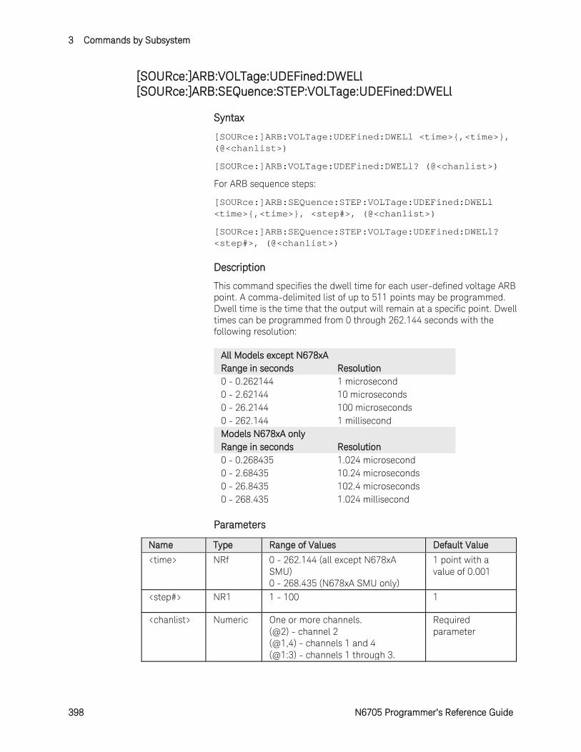
3 Commands by Subsystem
398 N6705 Programmer’s Reference Guide
[SOURce:]ARB:VOLTage:UDEFined:DWELl [SOURce:]ARB:SEQuence:STEP:VOLTage:UDEFined:DWELl
Syntax
[SOURce:]ARB:VOLTage:UDEFined:DWELl <time>,<time>, (@<chanlist>)
[SOURce:]ARB:VOLTage:UDEFined:DWELl? (@<chanlist>)
For ARB sequence steps:
[SOURce:]ARB:SEQuence:STEP:VOLTage:UDEFined:DWELl <time>,<time>, <step#>, (@<chanlist>)
[SOURce:]ARB:SEQuence:STEP:VOLTage:UDEFined:DWELl? <step#>, (@<chanlist>)
Description
This command specifies the dwell time for each user-defined voltage ARB point. A comma-delimited list of up to 511 points may be programmed. Dwell time is the time that the output will remain at a specific point. Dwell times can be programmed from 0 through 262.144 seconds with the following resolution:
All Models except N678xA Range in seconds Resolution 0 - 0.262144 1 microsecond 0 - 2.62144 10 microseconds 0 - 26.2144 100 microseconds 0 - 262.144 1 millisecond Models N678xA only Range in seconds Resolution 0 - 0.268435 1.024 microsecond 0 - 2.68435 10.24 microseconds 0 - 26.8435 102.4 microseconds 0 - 268.435 1.024 millisecond
Parameters
Name Type Range of Values Default Value
<time> NRf 0 - 262.144 (all except N678xA SMU) 0 - 268.435 (N678xA SMU only)
1 point with a value of 0.001
<step#> NR1 1 - 100 1
<chanlist> Numeric One or more channels. (@2) - channel 2 (@1,4) - channels 1 and 4 (@1:3) - channels 1 through 3.
Required parameter
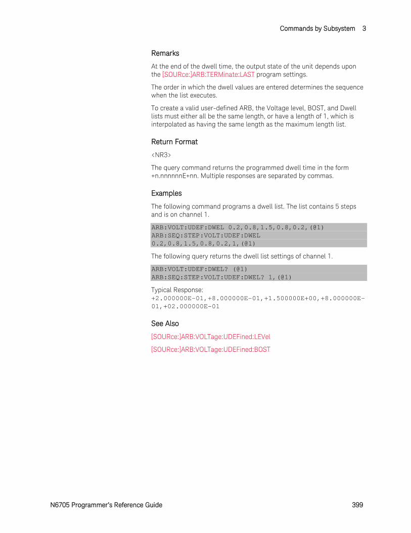
Commands by Subsystem 3
N6705 Programmer’s Reference Guide 399
Remarks
At the end of the dwell time, the output state of the unit depends upon the [SOURce:]ARB:TERMinate:LAST program settings.
The order in which the dwell values are entered determines the sequence when the list executes.
To create a valid user-defined ARB, the Voltage level, BOST, and Dwell lists must either all be the same length, or have a length of 1, which is interpolated as having the same length as the maximum length list.
Return Format
<NR3>
The query command returns the programmed dwell time in the form +n.nnnnnnE+nn. Multiple responses are separated by commas.
Examples
The following command programs a dwell list. The list contains 5 steps and is on channel 1.
ARB:VOLT:UDEF:DWEL 0.2,0.8,1.5,0.8,0.2,(@1) ARB:SEQ:STEP:VOLT:UDEF:DWEL 0.2,0.8,1.5,0.8,0.2,1,(@1)
The following query returns the dwell list settings of channel 1.
ARB:VOLT:UDEF:DWEL? (@1) ARB:SEQ:STEP:VOLT:UDEF:DWEL? 1,(@1)
Typical Response: +2.000000E-01,+8.000000E-01,+1.500000E+00,+8.000000E-01,+02.000000E-01
See Also
[SOURce:]ARB:VOLTage:UDEFined:LEVel
[SOURce:]ARB:VOLTage:UDEFined:BOST
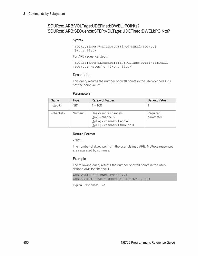
3 Commands by Subsystem
400 N6705 Programmer’s Reference Guide
[SOURce:]ARB:VOLTage:UDEFined:DWELl:POINts? [SOURce:]ARB:SEQuence:STEP:VOLTage:UDEFined:DWELl:POINts?
Syntax
[SOURce:]ARB:VOLTage:UDEFined:DWELl:POINts? (@<chanlist>)
For ARB sequence steps:
[SOURce:]ARB:SEQuence:STEP:VOLTage:UDEFined:DWELl :POINts? <step#>, (@<chanlist>)
Description
This query returns the number of dwell points in the user-defined ARB, not the point values.
Parameters
Name Type Range of Values Default Value
<step#> NR1 1 - 100 1
<chanlist> Numeric One or more channels. (@2) - channel 2 (@1,4) - channels 1 and 4 (@1:3) - channels 1 through 3.
Required parameter
Return Format
<NR1>
The number of dwell points in the user-defined ARB. Multiple responses are separated by commas.
Example
The following query returns the number of dwell points in the user-defined ARB for channel 1.
ARB:VOLT:UDEF:DWEL:POIN? (@1) ARB:SEQ:STEP:VOLT:UDEF:DWEL:POIN? 1,(@1)
Typical Response: +1
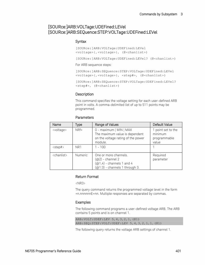
Commands by Subsystem 3
N6705 Programmer’s Reference Guide 401
[SOURce:]ARB:VOLTage:UDEFined:LEVel [SOURce:]ARB:SEQuence:STEP:VOLTage:UDEFined:LEVel
Syntax
[SOURce:]ARB:VOLTage:UDEFined:LEVel <voltage>,<voltage>, (@<chanlist>)
[SOURce:]ARB:VOLTage:UDEFined:LEVel? (@<chanlist>)
For ARB sequence steps:
[SOURce:]ARB:SEQuence:STEP:VOLTage:UDEFined:LEVel <voltage>,<voltage>, <step#>, (@<chanlist>)
[SOURce:]ARB:SEQuence:STEP:VOLTage:UDEFined:LEVel? <step#>, (@<chanlist>)
Description
This command specifies the voltage setting for each user-defined ARB point in volts. A comma-delimited list of up to 511 points may be programmed.
Parameters
Name Type Range of Values Default Value
<voltage> NRf+ 0 - maximum | MIN | MAX The maximum value is dependent on the voltage rating of the power module.
1 point set to the minimum programmable value
<step#> NR1 1 - 100 1
<chanlist> Numeric One or more channels. (@2) - channel 2 (@1,4) - channels 1 and 4 (@1:3) - channels 1 through 3.
Required parameter
Return Format
<NR3>
The query command returns the programmed voltage level in the form +n.nnnnnnE+nn. Multiple responses are separated by commas.
Examples
The following command programs a user-defined voltage ARB. The ARB contains 5 points and is on channel 1.
ARB:VOLT:UDEF:LEV 5,4,3,2,1,(@1) ARB:SEQ:STEP:VOLT:UDEF:LEV 5,4,3,2,1,1,(@1)
The following query returns the voltage ARB settings of channel 1.

3 Commands by Subsystem
402 N6705 Programmer’s Reference Guide
ARB:VOLT:UDEF:LEV? (@1) ARB:SEQ:STEP:VOLT:UDEF:LEV? 1,(@1)
Typical Response: +5.000000E+00,+4.000000E+00,+3.000000E+00, +2.000000E+00,+1.000000E+00
See Also
[SOURce:]ARB:VOLTage:UDEFined:DWELl
[SOURce:]ARB:VOLTage:UDEFined:BOST
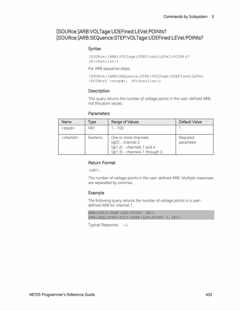
Commands by Subsystem 3
N6705 Programmer’s Reference Guide 403
[SOURce:]ARB:VOLTage:UDEFined:LEVel:POINts? [SOURce:]ARB:SEQuence:STEP:VOLTage:UDEFined:LEVel:POINts?
Syntax
[SOURce:]ARB:VOLTage:UDEFined:LEVel:POINts? (@<chanlist>)
For ARB sequence steps:
[SOURce:]ARB:SEQuence:STEP:VOLTage:UDEFined:LEVel :POINts? <step#>, (@<chanlist>)
Description
This query returns the number of voltage points in the user-defined ARB, not the point values.
Parameters
Name Type Range of Values Default Value
<step#> NR1 1 - 100 1
<chanlist> Numeric One or more channels. (@2) - channel 2 (@1,4) - channels 1 and 4 (@1:3) - channels 1 through 3.
Required parameter
Return Format
<NR1>
The number of voltage points in the user-defined ARB. Multiple responses are separated by commas.
Example
The following query returns the number of voltage points in a user-defined ARB for channel 1.
ARB:VOLT:UDEF:LEV:POIN? (@1) ARB:SEQ:STEP:VOLT:UDEF:LEV:POIN? 1,(@1)
Typical Response: +1
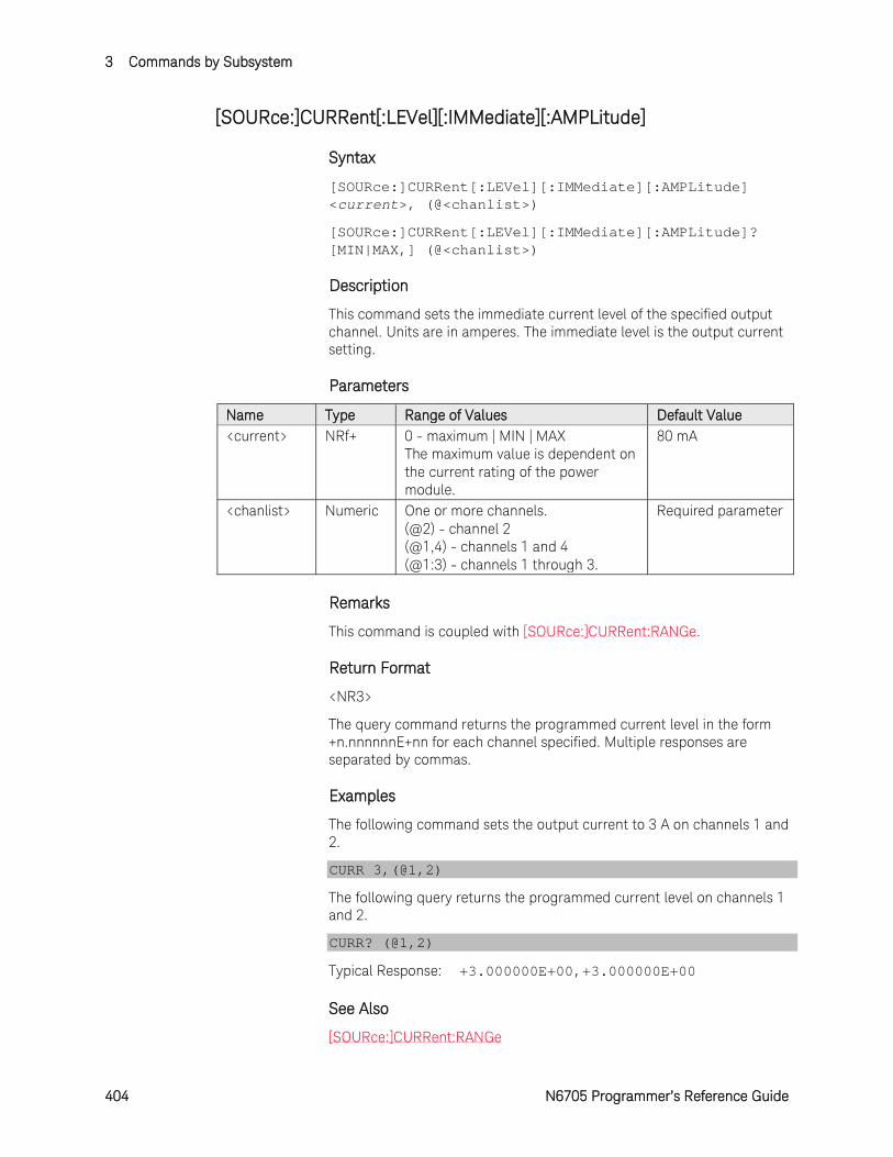
3 Commands by Subsystem
404 N6705 Programmer’s Reference Guide
[SOURce:]CURRent[:LEVel][:IMMediate][:AMPLitude]
Syntax
[SOURce:]CURRent[:LEVel][:IMMediate][:AMPLitude] <current>, (@<chanlist>)
[SOURce:]CURRent[:LEVel][:IMMediate][:AMPLitude]? [MIN|MAX,] (@<chanlist>)
Description
This command sets the immediate current level of the specified output channel. Units are in amperes. The immediate level is the output current setting.
Parameters
Name Type Range of Values Default Value <current> NRf+ 0 - maximum | MIN | MAX
The maximum value is dependent on the current rating of the power module.
80 mA
<chanlist> Numeric One or more channels. (@2) - channel 2 (@1,4) - channels 1 and 4 (@1:3) - channels 1 through 3.
Required parameter
Remarks
This command is coupled with [SOURce:]CURRent:RANGe.
Return Format
<NR3>
The query command returns the programmed current level in the form +n.nnnnnnE+nn for each channel specified. Multiple responses are separated by commas.
Examples
The following command sets the output current to 3 A on channels 1 and 2.
CURR 3,(@1,2)
The following query returns the programmed current level on channels 1 and 2.
CURR? (@1,2)
Typical Response: +3.000000E+00,+3.000000E+00
See Also
[SOURce:]CURRent:RANGe
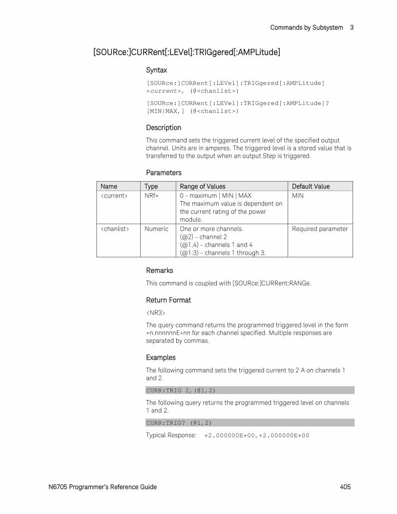
Commands by Subsystem 3
N6705 Programmer’s Reference Guide 405
[SOURce:]CURRent[:LEVel]:TRIGgered[:AMPLitude]
Syntax
[SOURce:]CURRent[:LEVel]:TRIGgered[:AMPLitude] <current>, (@<chanlist>)
[SOURce:]CURRent[:LEVel]:TRIGgered[:AMPLitude]? [MIN|MAX,] (@<chanlist>)
Description
This command sets the triggered current level of the specified output channel. Units are in amperes. The triggered level is a stored value that is transferred to the output when an output Step is triggered.
Parameters
Name Type Range of Values Default Value <current> NRf+ 0 - maximum | MIN | MAX
The maximum value is dependent on the current rating of the power module.
MIN
<chanlist> Numeric One or more channels. (@2) - channel 2 (@1,4) - channels 1 and 4 (@1:3) - channels 1 through 3.
Required parameter
Remarks
This command is coupled with [SOURce:]CURRent:RANGe.
Return Format
<NR3>
The query command returns the programmed triggered level in the form +n.nnnnnnE+nn for each channel specified. Multiple responses are separated by commas.
Examples
The following command sets the triggered current to 2 A on channels 1 and 2.
CURR:TRIG 2,(@1,2)
The following query returns the programmed triggered level on channels 1 and 2.
CURR:TRIG? (@1,2)
Typical Response: +2.000000E+00,+2.000000E+00

3 Commands by Subsystem
406 N6705 Programmer’s Reference Guide
See Also
[SOURce:]CURRent[:LEVel][:IMMediate]
[SOURce:]CURRent:MODE
TRIGger:TRANsient[:IMMediate]
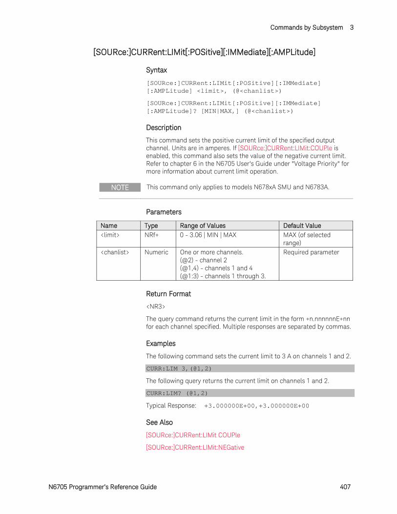
Commands by Subsystem 3
N6705 Programmer’s Reference Guide 407
[SOURce:]CURRent:LIMit[:POSitive][:IMMediate][:AMPLitude]
Syntax
[SOURce:]CURRent:LIMit[:POSitive][:IMMediate] [:AMPLitude] <limit>, (@<chanlist>)
[SOURce:]CURRent:LIMit[:POSitive][:IMMediate] [:AMPLitude]? [MIN|MAX,] (@<chanlist>)
Description
This command sets the positive current limit of the specified output channel. Units are in amperes. If [SOURce:]CURRent:LIMit:COUPle is enabled, this command also sets the value of the negative current limit. Refer to chapter 6 in the N6705 User's Guide under "Voltage Priority" for more information about current limit operation.
NOTE This command only applies to models N678xA SMU and N6783A.
Parameters
Name Type Range of Values Default Value <limit> NRf+ 0 - 3.06 | MIN | MAX MAX (of selected
range) <chanlist> Numeric One or more channels.
(@2) - channel 2 (@1,4) - channels 1 and 4 (@1:3) - channels 1 through 3.
Required parameter
Return Format
<NR3>
The query command returns the current limit in the form +n.nnnnnnE+nn for each channel specified. Multiple responses are separated by commas.
Examples
The following command sets the current limit to 3 A on channels 1 and 2.
CURR:LIM 3,(@1,2)
The following query returns the current limit on channels 1 and 2.
CURR:LIM? (@1,2)
Typical Response: +3.000000E+00,+3.000000E+00
See Also
[SOURce:]CURRent:LIMit COUPle
[SOURce:]CURRent:LIMit:NEGative
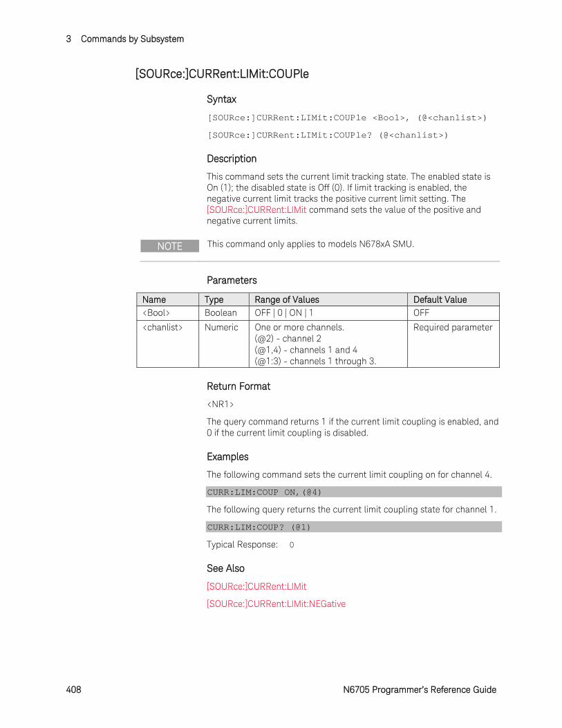
3 Commands by Subsystem
408 N6705 Programmer’s Reference Guide
[SOURce:]CURRent:LIMit:COUPle
Syntax
[SOURce:]CURRent:LIMit:COUPle <Bool>, (@<chanlist>)
[SOURce:]CURRent:LIMit:COUPle? (@<chanlist>)
Description
This command sets the current limit tracking state. The enabled state is On (1); the disabled state is Off (0). If limit tracking is enabled, the negative current limit tracks the positive current limit setting. The [SOURce:]CURRent:LIMit command sets the value of the positive and negative current limits.
NOTE This command only applies to models N678xA SMU.
Parameters
Name Type Range of Values Default Value <Bool> Boolean OFF | 0 | ON | 1 OFF
<chanlist> Numeric One or more channels. (@2) - channel 2 (@1,4) - channels 1 and 4 (@1:3) - channels 1 through 3.
Required parameter
Return Format
<NR1>
The query command returns 1 if the current limit coupling is enabled, and 0 if the current limit coupling is disabled.
Examples
The following command sets the current limit coupling on for channel 4.
CURR:LIM:COUP ON,(@4)
The following query returns the current limit coupling state for channel 1.
CURR:LIM:COUP? (@1)
Typical Response: 0
See Also
[SOURce:]CURRent:LIMit
[SOURce:]CURRent:LIMit:NEGative
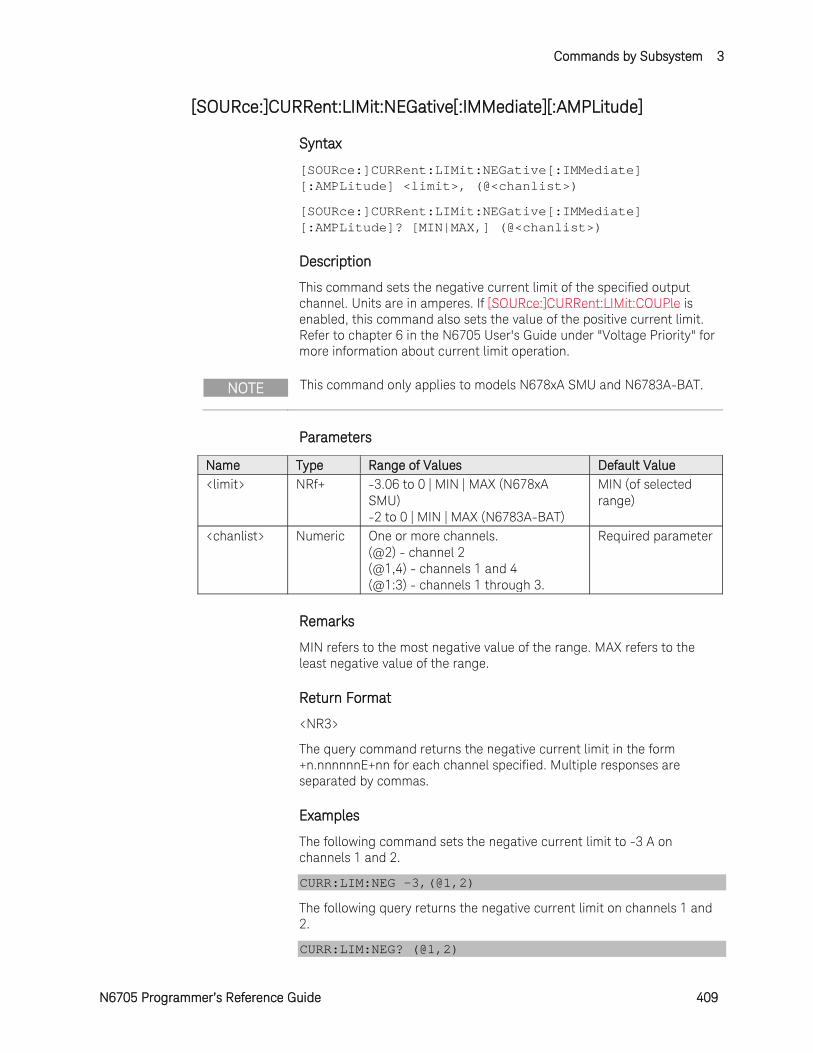
Commands by Subsystem 3
N6705 Programmer’s Reference Guide 409
[SOURce:]CURRent:LIMit:NEGative[:IMMediate][:AMPLitude]
Syntax
[SOURce:]CURRent:LIMit:NEGative[:IMMediate] [:AMPLitude] <limit>, (@<chanlist>)
[SOURce:]CURRent:LIMit:NEGative[:IMMediate] [:AMPLitude]? [MIN|MAX,] (@<chanlist>)
Description
This command sets the negative current limit of the specified output channel. Units are in amperes. If [SOURce:]CURRent:LIMit:COUPle is enabled, this command also sets the value of the positive current limit. Refer to chapter 6 in the N6705 User's Guide under "Voltage Priority" for more information about current limit operation.
NOTE This command only applies to models N678xA SMU and N6783A-BAT.
Parameters
Name Type Range of Values Default Value <limit> NRf+ -3.06 to 0 | MIN | MAX (N678xA
SMU) -2 to 0 | MIN | MAX (N6783A-BAT)
MIN (of selected range)
<chanlist> Numeric One or more channels. (@2) - channel 2 (@1,4) - channels 1 and 4 (@1:3) - channels 1 through 3.
Required parameter
Remarks
MIN refers to the most negative value of the range. MAX refers to the least negative value of the range.
Return Format
<NR3>
The query command returns the negative current limit in the form +n.nnnnnnE+nn for each channel specified. Multiple responses are separated by commas.
Examples
The following command sets the negative current limit to -3 A on channels 1 and 2.
CURR:LIM:NEG -3,(@1,2)
The following query returns the negative current limit on channels 1 and 2.
CURR:LIM:NEG? (@1,2)
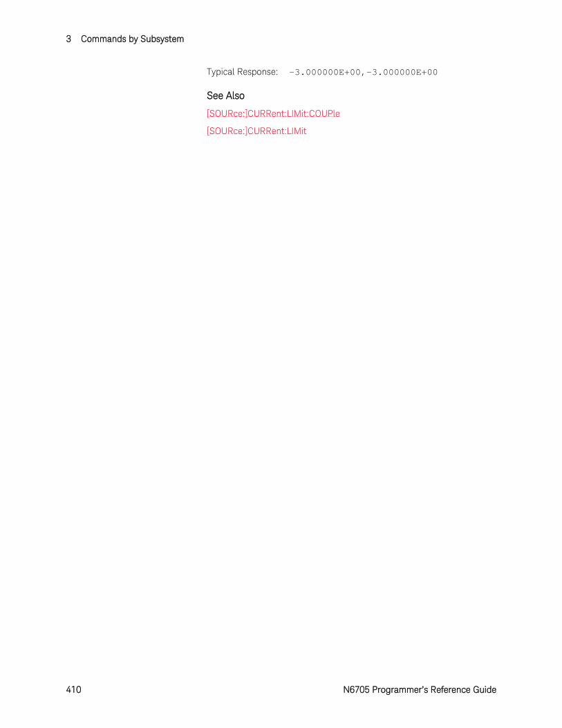
3 Commands by Subsystem
410 N6705 Programmer’s Reference Guide
Typical Response: -3.000000E+00,-3.000000E+00
See Also
[SOURce:]CURRent:LIMit:COUPle
[SOURce:]CURRent:LIMit
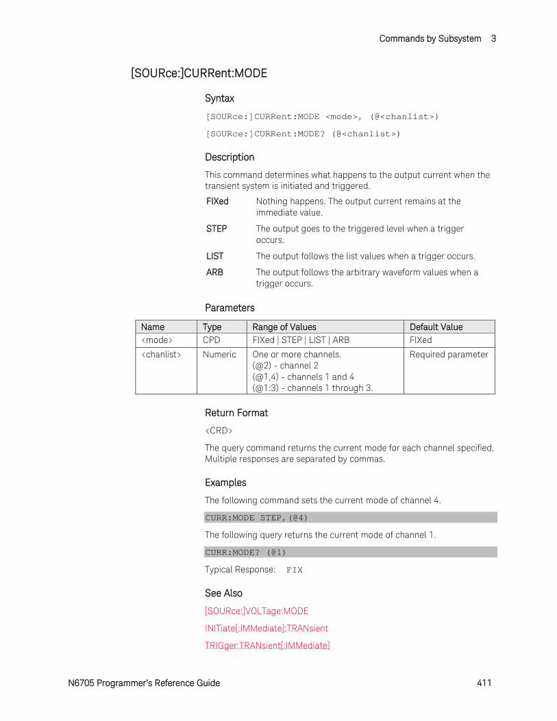
Commands by Subsystem 3
N6705 Programmer’s Reference Guide 411
[SOURce:]CURRent:MODE
Syntax
[SOURce:]CURRent:MODE <mode>, (@<chanlist>)
[SOURce:]CURRent:MODE? (@<chanlist>)
Description
This command determines what happens to the output current when the transient system is initiated and triggered.
FIXed Nothing happens. The output current remains at the immediate value.
STEP The output goes to the triggered level when a trigger occurs.
LIST The output follows the list values when a trigger occurs.
ARB The output follows the arbitrary waveform values when a trigger occurs.
Parameters
Name Type Range of Values Default Value <mode> CPD FIXed | STEP | LIST | ARB FIXed
<chanlist> Numeric One or more channels. (@2) - channel 2 (@1,4) - channels 1 and 4 (@1:3) - channels 1 through 3.
Required parameter
Return Format
<CRD>
The query command returns the current mode for each channel specified. Multiple responses are separated by commas.
Examples
The following command sets the current mode of channel 4.
CURR:MODE STEP,(@4)
The following query returns the current mode of channel 1.
CURR:MODE? (@1)
Typical Response: FIX
See Also
[SOURce:]VOLTage:MODE
INITiate[:IMMediate]:TRANsient
TRIGger:TRANsient[:IMMediate]
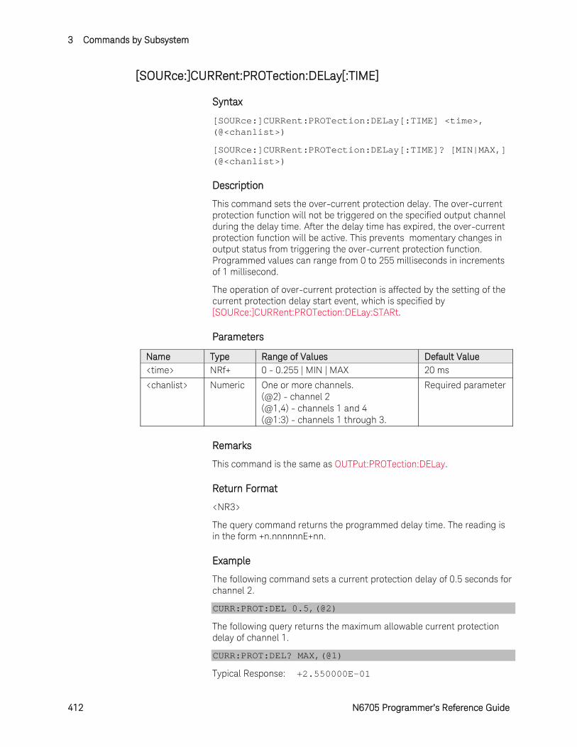
3 Commands by Subsystem
412 N6705 Programmer’s Reference Guide
[SOURce:]CURRent:PROTection:DELay[:TIME]
Syntax
[SOURce:]CURRent:PROTection:DELay[:TIME] <time>, (@<chanlist>)
[SOURce:]CURRent:PROTection:DELay[:TIME]? [MIN|MAX,] (@<chanlist>)
Description
This command sets the over-current protection delay. The over-current protection function will not be triggered on the specified output channel during the delay time. After the delay time has expired, the over-current protection function will be active. This prevents momentary changes in output status from triggering the over-current protection function. Programmed values can range from 0 to 255 milliseconds in increments of 1 millisecond.
The operation of over-current protection is affected by the setting of the current protection delay start event, which is specified by [SOURce:]CURRent:PROTection:DELay:STARt.
Parameters
Name Type Range of Values Default Value <time> NRf+ 0 - 0.255 | MIN | MAX 20 ms
<chanlist> Numeric One or more channels. (@2) - channel 2 (@1,4) - channels 1 and 4 (@1:3) - channels 1 through 3.
Required parameter
Remarks
This command is the same as OUTPut:PROTection:DELay.
Return Format
<NR3>
The query command returns the programmed delay time. The reading is in the form +n.nnnnnnE+nn.
Example
The following command sets a current protection delay of 0.5 seconds for channel 2.
CURR:PROT:DEL 0.5,(@2)
The following query returns the maximum allowable current protection delay of channel 1.
CURR:PROT:DEL? MAX,(@1)
Typical Response: +2.550000E-01
Commands by Subsystem 3
N6705 Programmer’s Reference Guide 413
See Also
[SOURce:]CURRent:PROTection:DELay
[SOURce:]CURRent:PROTection:DELay:STARt
[SOURce:]CURRent:PROTection:STATe
OUTPut:PROTection:CLEar
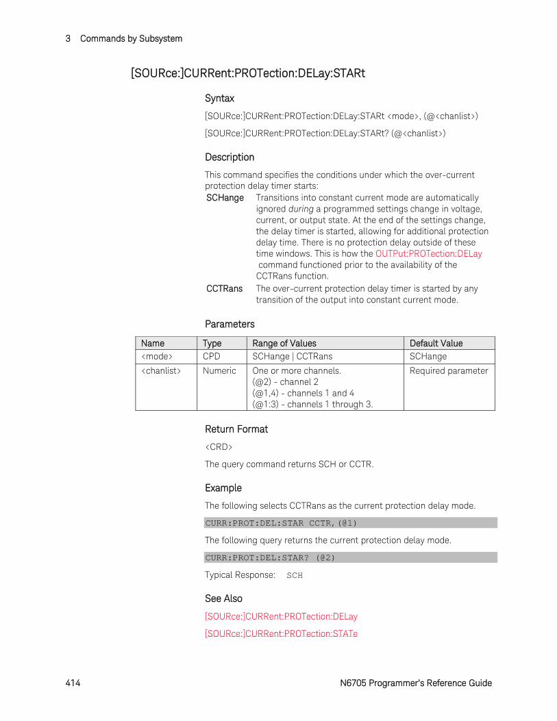
3 Commands by Subsystem
414 N6705 Programmer’s Reference Guide
[SOURce:]CURRent:PROTection:DELay:STARt
Syntax
[SOURce:]CURRent:PROTection:DELay:STARt <mode>, (@<chanlist>)
[SOURce:]CURRent:PROTection:DELay:STARt? (@<chanlist>)
Description
This command specifies the conditions under which the over-current protection delay timer starts: SCHange Transitions into constant current mode are automatically
ignored during a programmed settings change in voltage, current, or output state. At the end of the settings change, the delay timer is started, allowing for additional protection delay time. There is no protection delay outside of these time windows. This is how the OUTPut:PROTection:DELay command functioned prior to the availability of the CCTRans function.
CCTRans The over-current protection delay timer is started by any transition of the output into constant current mode.
Parameters
Name Type Range of Values Default Value <mode> CPD SCHange | CCTRans SCHange
<chanlist> Numeric One or more channels. (@2) - channel 2 (@1,4) - channels 1 and 4 (@1:3) - channels 1 through 3.
Required parameter
Return Format
<CRD>
The query command returns SCH or CCTR.
Example
The following selects CCTRans as the current protection delay mode.
CURR:PROT:DEL:STAR CCTR,(@1)
The following query returns the current protection delay mode.
CURR:PROT:DEL:STAR? (@2)
Typical Response: SCH
See Also
[SOURce:]CURRent:PROTection:DELay
[SOURce:]CURRent:PROTection:STATe
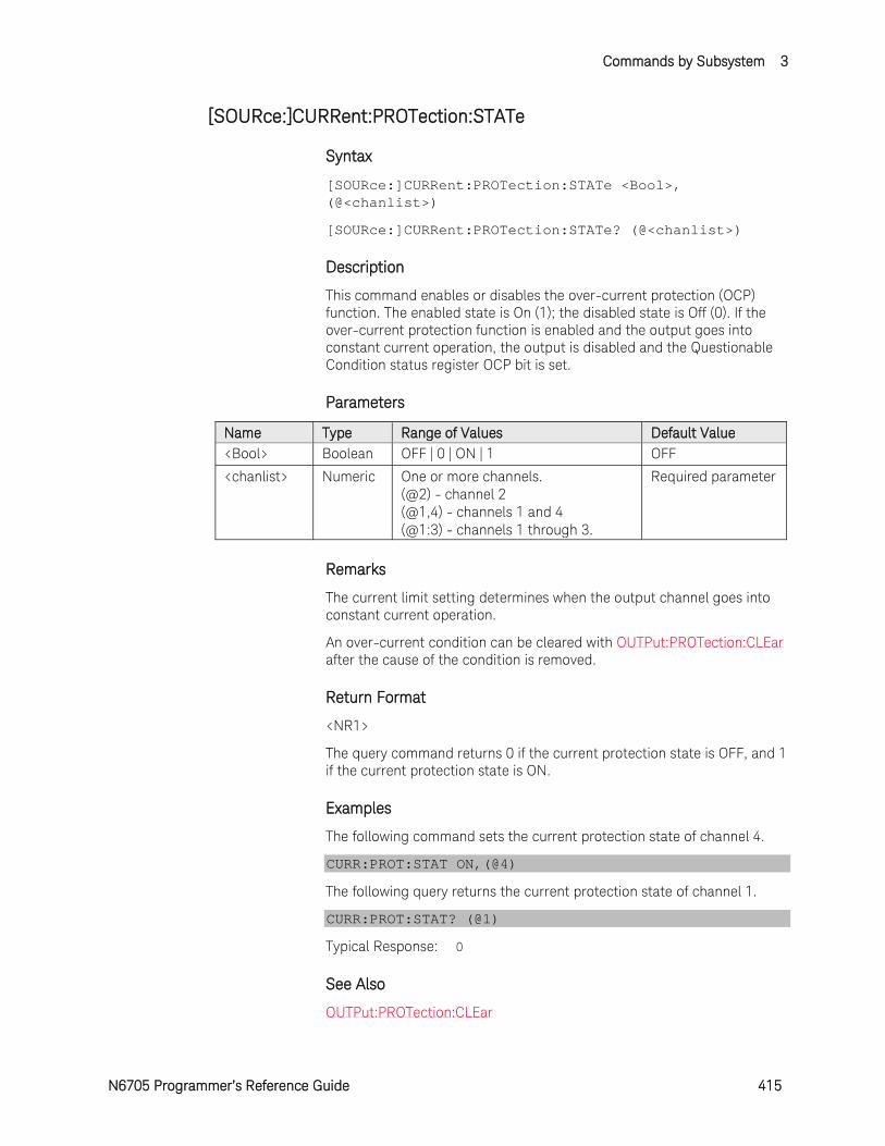
Commands by Subsystem 3
N6705 Programmer’s Reference Guide 415
[SOURce:]CURRent:PROTection:STATe
Syntax
[SOURce:]CURRent:PROTection:STATe <Bool>, (@<chanlist>)
[SOURce:]CURRent:PROTection:STATe? (@<chanlist>)
Description
This command enables or disables the over-current protection (OCP) function. The enabled state is On (1); the disabled state is Off (0). If the over-current protection function is enabled and the output goes into constant current operation, the output is disabled and the Questionable Condition status register OCP bit is set.
Parameters
Name Type Range of Values Default Value <Bool> Boolean OFF | 0 | ON | 1 OFF
<chanlist> Numeric One or more channels. (@2) - channel 2 (@1,4) - channels 1 and 4 (@1:3) - channels 1 through 3.
Required parameter
Remarks
The current limit setting determines when the output channel goes into constant current operation.
An over-current condition can be cleared with OUTPut:PROTection:CLEar after the cause of the condition is removed.
Return Format
<NR1>
The query command returns 0 if the current protection state is OFF, and 1 if the current protection state is ON.
Examples
The following command sets the current protection state of channel 4.
CURR:PROT:STAT ON,(@4)
The following query returns the current protection state of channel 1.
CURR:PROT:STAT? (@1)
Typical Response: 0
See Also
OUTPut:PROTection:CLEar

3 Commands by Subsystem
416 N6705 Programmer’s Reference Guide
[SOURce:]CURRent:RANGe
Syntax
[SOURce:]CURRent:RANGe <range>, (@<chanlist>)
[SOURce:]CURRent:RANGe? [MIN|MAX,] (@<chanlist>)
Description
This command sets the output current range on models that have multiple ranges. The value that you enter must be the highest value in amperes that you expect to source. The instrument selects the range with the best resolution for the value entered.
Parameters
Name Type Range of Values Default Value <range> NRf+ 0 - maximum | MIN | MAX
Values entered are model dependent.
MAX
<chanlist> Numeric One or more channels. (@2) - channel 2 (@1,4) - channels 1 and 4 (@1:3) - channels 1 through 3.
Required parameter
Remarks
This command is coupled with the [SOURce:]CURRent command. This means that if a range command is sent that places an output on a range with a lower maximum current than the present current level, an error is generated. This also occurs if a current level is programmed with a value too large for the present range.
These types of errors can be avoided by sending the both level and range commands in the same SCPI message. When the range and setting information is received as a set, no range/setting conflict occurs.
If programming a range value causes a range change to occur while the output is enabled, the output will be temporarily disabled while the range switch occurs. The transition from on-to-off and then from off-to-on will also be delayed by the settings of OUTPut:DELay:FALL and OUTPut:DELay:RISE.
Return Format
<NR3>
The query command returns the maximum current that can be output on the range that is presently set. The current level is in the form +n.nnnnnnE+nn for each channel specified. Multiple responses are separated by commas.
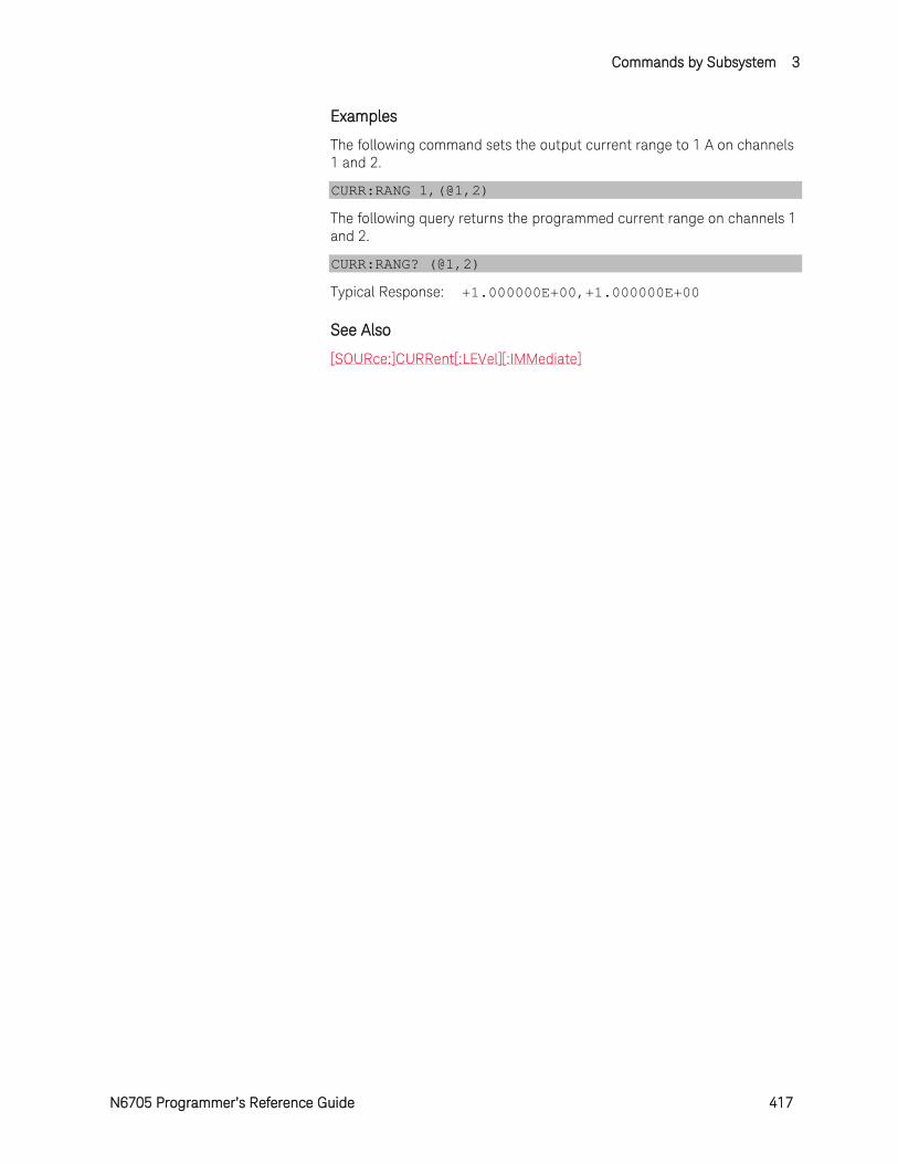
Commands by Subsystem 3
N6705 Programmer’s Reference Guide 417
Examples
The following command sets the output current range to 1 A on channels 1 and 2.
CURR:RANG 1,(@1,2)
The following query returns the programmed current range on channels 1 and 2.
CURR:RANG? (@1,2)
Typical Response: +1.000000E+00,+1.000000E+00
See Also
[SOURce:]CURRent[:LEVel][:IMMediate]
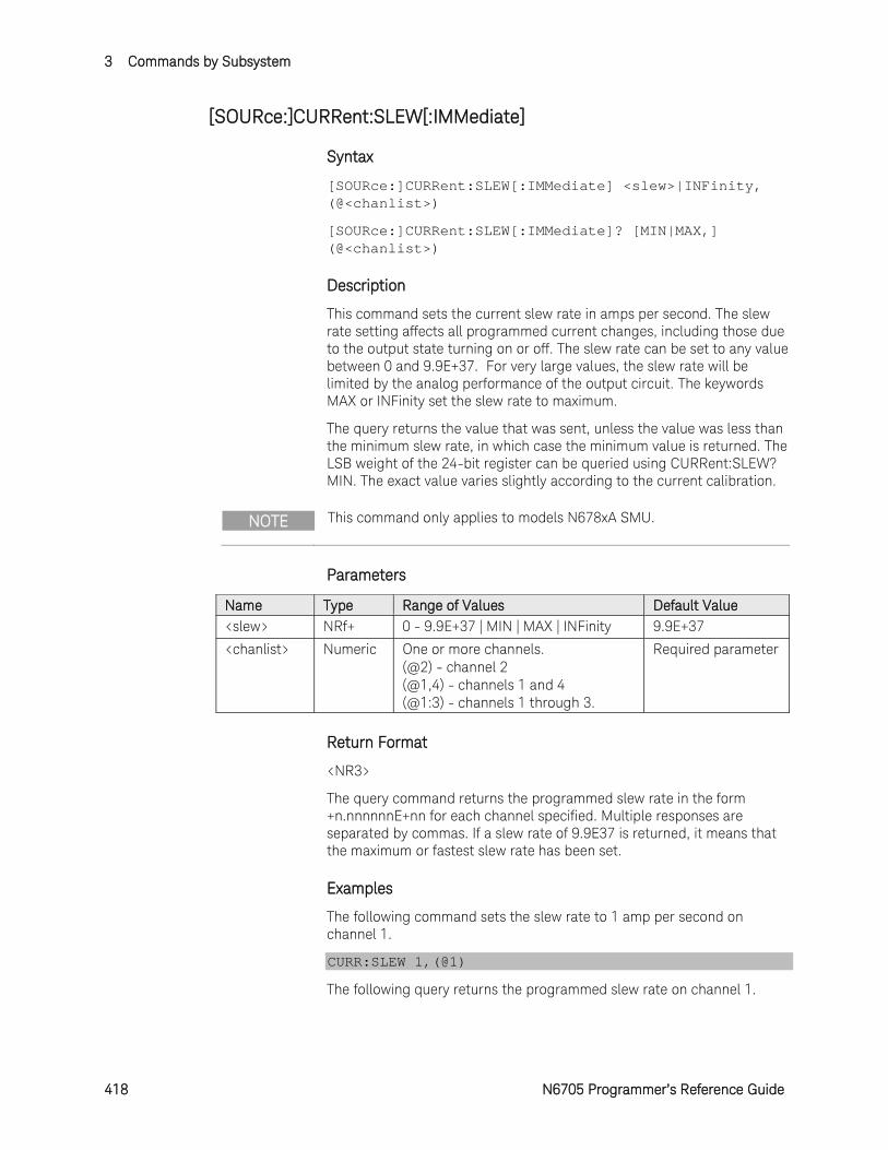
3 Commands by Subsystem
418 N6705 Programmer’s Reference Guide
[SOURce:]CURRent:SLEW[:IMMediate]
Syntax
[SOURce:]CURRent:SLEW[:IMMediate] <slew>|INFinity, (@<chanlist>)
[SOURce:]CURRent:SLEW[:IMMediate]? [MIN|MAX,] (@<chanlist>)
Description
This command sets the current slew rate in amps per second. The slew rate setting affects all programmed current changes, including those due to the output state turning on or off. The slew rate can be set to any value between 0 and 9.9E+37. For very large values, the slew rate will be limited by the analog performance of the output circuit. The keywords MAX or INFinity set the slew rate to maximum.
The query returns the value that was sent, unless the value was less than the minimum slew rate, in which case the minimum value is returned. The LSB weight of the 24-bit register can be queried using CURRent:SLEW? MIN. The exact value varies slightly according to the current calibration.
NOTE This command only applies to models N678xA SMU.
Parameters
Name Type Range of Values Default Value <slew> NRf+ 0 - 9.9E+37 | MIN | MAX | INFinity 9.9E+37
<chanlist> Numeric One or more channels. (@2) - channel 2 (@1,4) - channels 1 and 4 (@1:3) - channels 1 through 3.
Required parameter
Return Format
<NR3>
The query command returns the programmed slew rate in the form +n.nnnnnnE+nn for each channel specified. Multiple responses are separated by commas. If a slew rate of 9.9E37 is returned, it means that the maximum or fastest slew rate has been set.
Examples
The following command sets the slew rate to 1 amp per second on channel 1.
CURR:SLEW 1,(@1)
The following query returns the programmed slew rate on channel 1.
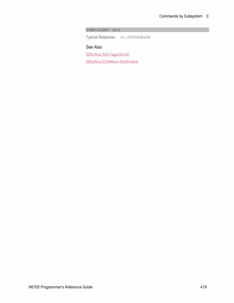
Commands by Subsystem 3
N6705 Programmer’s Reference Guide 419
CURR:SLEW? (@1)
Typical Response: +1.000000E+00
See Also
[SOURce:]VOLTage:SLEW
[SOURce:]CURRent:SLEW:MAX
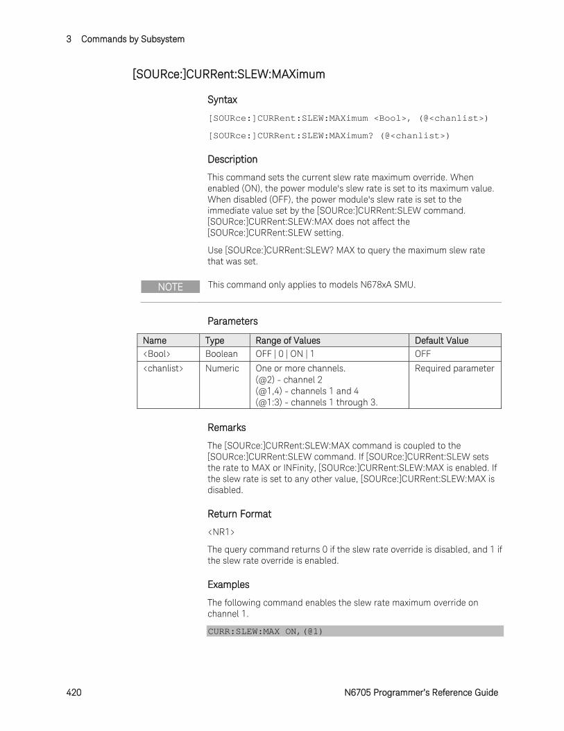
3 Commands by Subsystem
420 N6705 Programmer’s Reference Guide
[SOURce:]CURRent:SLEW:MAXimum
Syntax
[SOURce:]CURRent:SLEW:MAXimum <Bool>, (@<chanlist>)
[SOURce:]CURRent:SLEW:MAXimum? (@<chanlist>)
Description
This command sets the current slew rate maximum override. When enabled (ON), the power module's slew rate is set to its maximum value. When disabled (OFF), the power module's slew rate is set to the immediate value set by the [SOURce:]CURRent:SLEW command. [SOURce:]CURRent:SLEW:MAX does not affect the [SOURce:]CURRent:SLEW setting.
Use [SOURce:]CURRent:SLEW? MAX to query the maximum slew rate that was set.
NOTE This command only applies to models N678xA SMU.
Parameters
Name Type Range of Values Default Value <Bool> Boolean OFF | 0 | ON | 1 OFF
<chanlist> Numeric One or more channels. (@2) - channel 2 (@1,4) - channels 1 and 4 (@1:3) - channels 1 through 3.
Required parameter
Remarks
The [SOURce:]CURRent:SLEW:MAX command is coupled to the [SOURce:]CURRent:SLEW command. If [SOURce:]CURRent:SLEW sets the rate to MAX or INFinity, [SOURce:]CURRent:SLEW:MAX is enabled. If the slew rate is set to any other value, [SOURce:]CURRent:SLEW:MAX is disabled.
Return Format
<NR1>
The query command returns 0 if the slew rate override is disabled, and 1 if the slew rate override is enabled.
Examples
The following command enables the slew rate maximum override on channel 1.
CURR:SLEW:MAX ON,(@1)
Commands by Subsystem 3
N6705 Programmer’s Reference Guide 421
The following query returns the state of the slew rate override on channel 1.
CURR:SLEW:MAX? (@1)
Typical Response: 1
See Also
[SOURce:]CURRent:SLEW
[SOURce:]VOLTage:SLEW:MAXimum
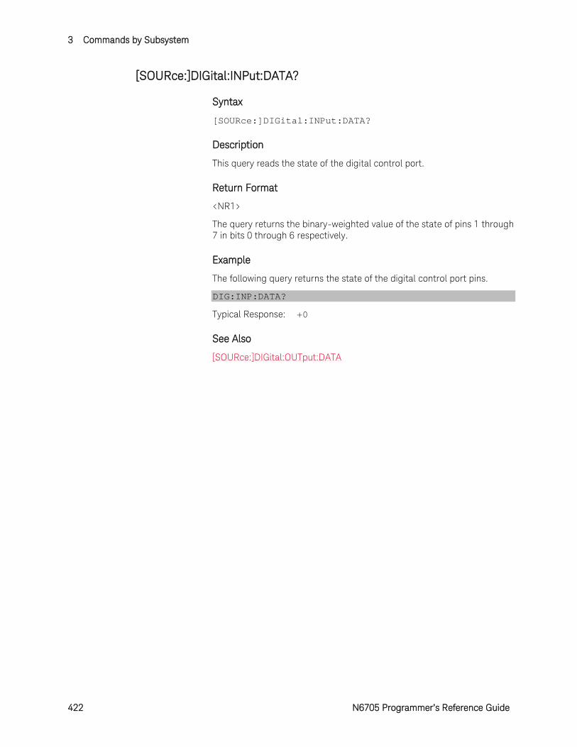
3 Commands by Subsystem
422 N6705 Programmer’s Reference Guide
[SOURce:]DIGital:INPut:DATA?
Syntax
[SOURce:]DIGital:INPut:DATA?
Description
This query reads the state of the digital control port.
Return Format
<NR1>
The query returns the binary-weighted value of the state of pins 1 through 7 in bits 0 through 6 respectively.
Example
The following query returns the state of the digital control port pins.
DIG:INP:DATA?
Typical Response: +0
See Also
[SOURce:]DIGital:OUTput:DATA
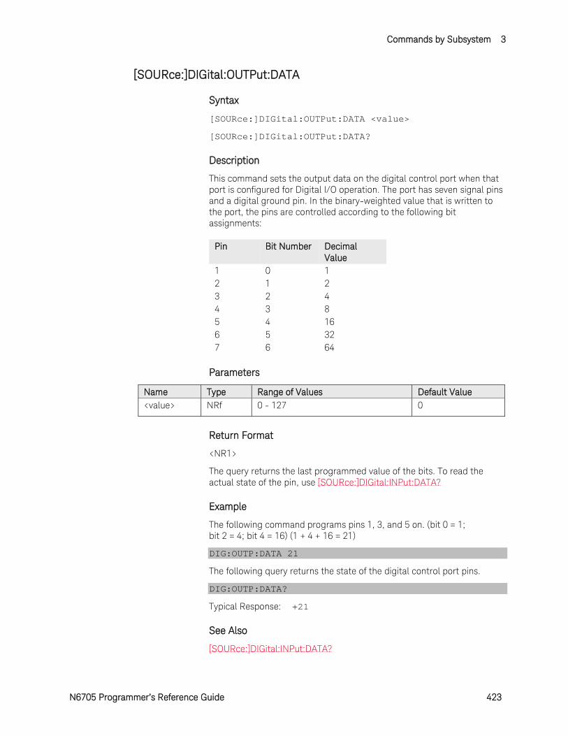
Commands by Subsystem 3
N6705 Programmer’s Reference Guide 423
[SOURce:]DIGital:OUTPut:DATA
Syntax
[SOURce:]DIGital:OUTPut:DATA <value>
[SOURce:]DIGital:OUTPut:DATA?
Description
This command sets the output data on the digital control port when that port is configured for Digital I/O operation. The port has seven signal pins and a digital ground pin. In the binary-weighted value that is written to the port, the pins are controlled according to the following bit assignments:
Pin Bit Number Decimal Value
1 0 1 2 1 2 3 2 4 4 3 8 5 4 16 6 5 32 7 6 64
Parameters
Name Type Range of Values Default Value <value> NRf 0 - 127 0
Return Format
<NR1>
The query returns the last programmed value of the bits. To read the actual state of the pin, use [SOURce:]DIGital:INPut:DATA?
Example
The following command programs pins 1, 3, and 5 on. (bit 0 = 1; bit 2 = 4; bit 4 = 16) (1 + 4 + 16 = 21)
DIG:OUTP:DATA 21
The following query returns the state of the digital control port pins.
DIG:OUTP:DATA?
Typical Response: +21
See Also
[SOURce:]DIGital:INPut:DATA?
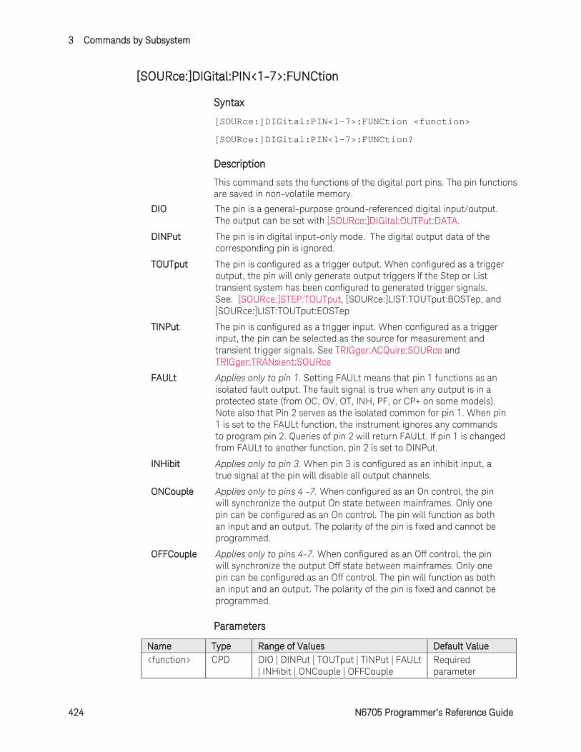
3 Commands by Subsystem
424 N6705 Programmer’s Reference Guide
[SOURce:]DIGital:PIN<1-7>:FUNCtion
Syntax
[SOURce:]DIGital:PIN<1-7>:FUNCtion <function>
[SOURce:]DIGital:PIN<1-7>:FUNCtion?
Description
This command sets the functions of the digital port pins. The pin functions are saved in non-volatile memory.
DIO The pin is a general-purpose ground-referenced digital input/output. The output can be set with [SOURce:]DIGital:OUTPut:DATA.
DINPut The pin is in digital input-only mode. The digital output data of the corresponding pin is ignored.
TOUTput The pin is configured as a trigger output. When configured as a trigger output, the pin will only generate output triggers if the Step or List transient system has been configured to generated trigger signals. See: [SOURce:]STEP:TOUTput, [SOURce:]LIST:TOUTput:BOSTep, and [SOURce:]LIST:TOUTput:EOSTep
TINPut The pin is configured as a trigger input. When configured as a trigger input, the pin can be selected as the source for measurement and transient trigger signals. See TRIGger:ACQuire:SOURce and TRIGger:TRANsient:SOURce
FAULt Applies only to pin 1. Setting FAULt means that pin 1 functions as an isolated fault output. The fault signal is true when any output is in a protected state (from OC, OV, OT, INH, PF, or CP+ on some models). Note also that Pin 2 serves as the isolated common for pin 1. When pin 1 is set to the FAULt function, the instrument ignores any commands to program pin 2. Queries of pin 2 will return FAULt. If pin 1 is changed from FAULt to another function, pin 2 is set to DINPut.
INHibit Applies only to pin 3. When pin 3 is configured as an inhibit input, a true signal at the pin will disable all output channels.
ONCouple Applies only to pins 4 -7. When configured as an On control, the pin will synchronize the output On state between mainframes. Only one pin can be configured as an On control. The pin will function as both an input and an output. The polarity of the pin is fixed and cannot be programmed.
OFFCouple Applies only to pins 4-7. When configured as an Off control, the pin will synchronize the output Off state between mainframes. Only one pin can be configured as an Off control. The pin will function as both an input and an output. The polarity of the pin is fixed and cannot be programmed.
Parameters
Name Type Range of Values Default Value <function> CPD DIO | DINPut | TOUTput | TINPut | FAULt
| INHibit | ONCouple | OFFCouple Required parameter
Commands by Subsystem 3
N6705 Programmer’s Reference Guide 425
Return Format
<CRD>
The query command returns DIO, DINP, TOUT, TINP, FAUL, INH, ONC, or OFFC.
Example
The following command sets pin 1 to Fault mode.
DIG:PIN1:FUNC FAUL
The following query returns the setting of pin 7.
DIG:PIN7:FUNC?
Typical Response: DIO
See Also
[SOURce:]DIGital:PIN<1-7>:POLarity
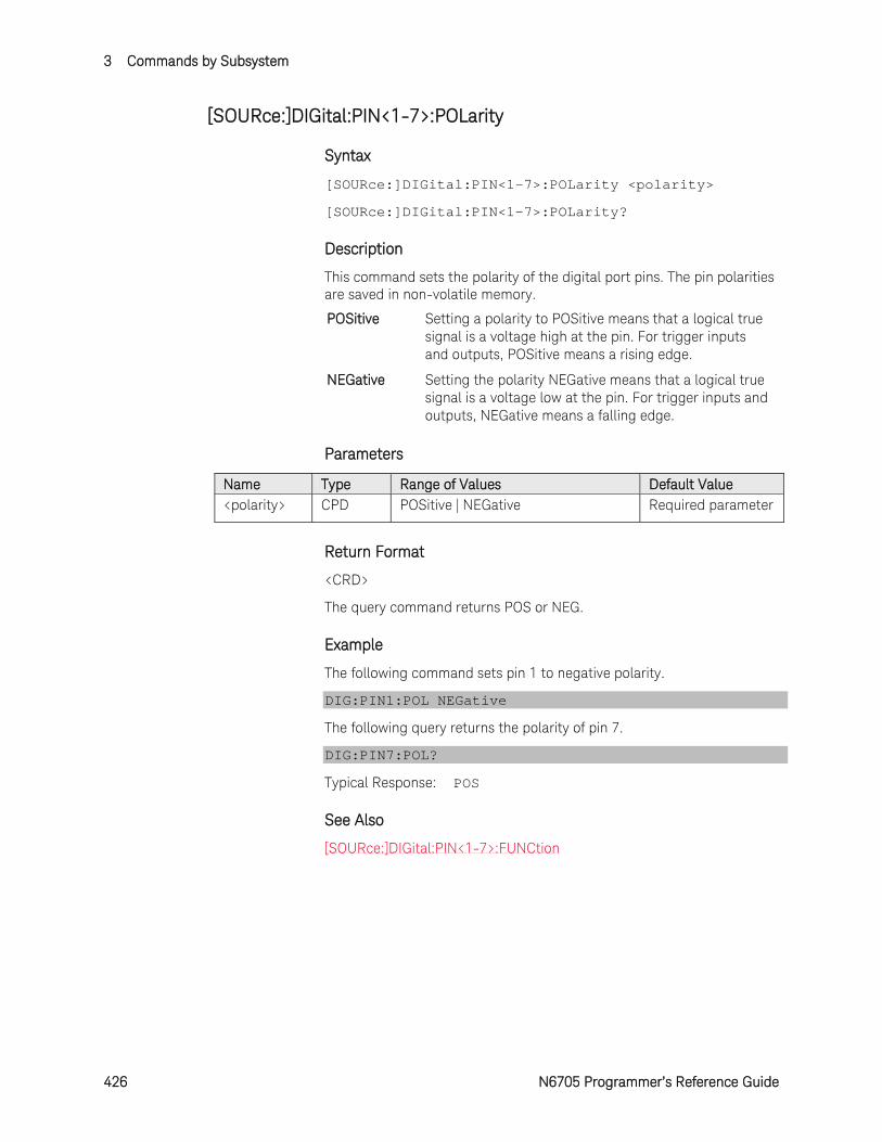
3 Commands by Subsystem
426 N6705 Programmer’s Reference Guide
[SOURce:]DIGital:PIN<1-7>:POLarity
Syntax
[SOURce:]DIGital:PIN<1-7>:POLarity <polarity>
[SOURce:]DIGital:PIN<1-7>:POLarity?
Description
This command sets the polarity of the digital port pins. The pin polarities are saved in non-volatile memory.
POSitive Setting a polarity to POSitive means that a logical true signal is a voltage high at the pin. For trigger inputs and outputs, POSitive means a rising edge.
NEGative Setting the polarity NEGative means that a logical true signal is a voltage low at the pin. For trigger inputs and outputs, NEGative means a falling edge.
Parameters
Name Type Range of Values Default Value <polarity> CPD POSitive | NEGative Required parameter
Return Format
<CRD>
The query command returns POS or NEG.
Example
The following command sets pin 1 to negative polarity.
DIG:PIN1:POL NEGative
The following query returns the polarity of pin 7.
DIG:PIN7:POL?
Typical Response: POS
See Also
[SOURce:]DIGital:PIN<1-7>:FUNCtion
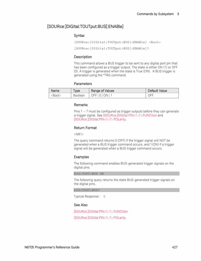
Commands by Subsystem 3
N6705 Programmer’s Reference Guide 427
[SOURce:]DIGital:TOUTput:BUS[:ENABle]
Syntax
[SOURce:]DIGital:TOUTput:BUS[:ENABle] <Bool>
[SOURce:]DIGital:TOUTput:BUS[:ENABle]?
Description
This command allows a BUS trigger to be sent to any digital port pin that has been configured as a trigger output. The state is either ON (1) or OFF (0). A trigger is generated when the state is True (ON). A BUS trigger is generated using the *TRG command.
Parameters
Name Type Range of Values Default Value <Bool> Boolean OFF | 0 | ON | 1 OFF
Remarks
Pins 1 – 7 must be configured as trigger outputs before they can generate a trigger signal. See [SOURce:]DIGital:PIN<1-7>:FUNCtion and [SOURce:]DIGital:PIN<1-7>:POLarity.
Return Format
<NR1>
The query command returns 0 (OFF) if the trigger signal will NOT be generated when a BUS trigger command occurs, and 1(ON) if a trigger signal will be generated when a BUS trigger command occurs.
Examples
The following command enables BUS-generated trigger signals on the digital pins.
DIG:TOUT:BUS ON
The following query returns the state BUS-generated trigger signals on the digital pins.
DIG:TOUT:BUS?
Typical Response: 0
See Also
[SOURce:]DIGital:PIN<1-7>:FUNCtion
[SOURce:]DIGital:PIN<1-7>:POLarity
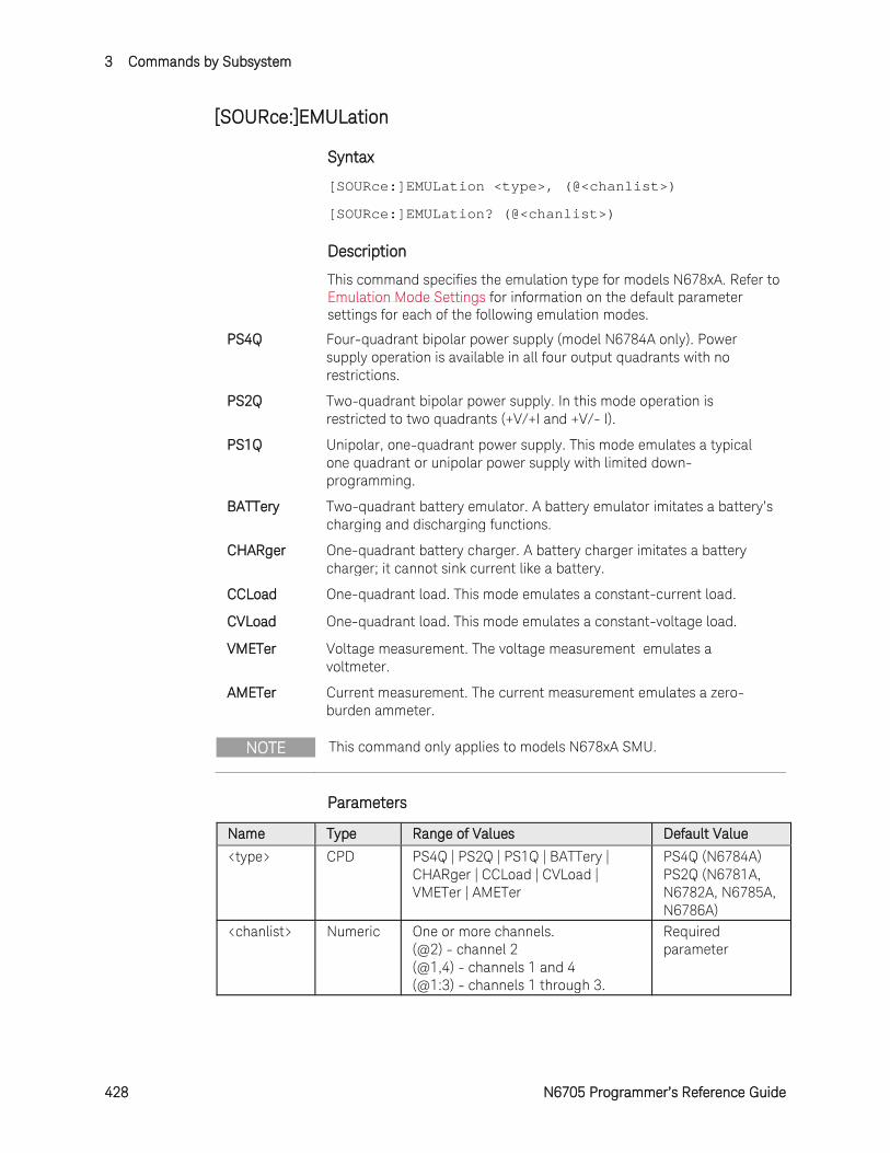
3 Commands by Subsystem
428 N6705 Programmer’s Reference Guide
[SOURce:]EMULation
Syntax
[SOURce:]EMULation <type>, (@<chanlist>)
[SOURce:]EMULation? (@<chanlist>)
Description
This command specifies the emulation type for models N678xA. Refer to Emulation Mode Settings for information on the default parameter settings for each of the following emulation modes.
PS4Q Four-quadrant bipolar power supply (model N6784A only). Power supply operation is available in all four output quadrants with no restrictions.
PS2Q Two-quadrant bipolar power supply. In this mode operation is restricted to two quadrants (+V/+I and +V/- I).
PS1Q Unipolar, one-quadrant power supply. This mode emulates a typical one quadrant or unipolar power supply with limited down-programming.
BATTery Two-quadrant battery emulator. A battery emulator imitates a battery’s charging and discharging functions.
CHARger One-quadrant battery charger. A battery charger imitates a battery charger; it cannot sink current like a battery.
CCLoad One-quadrant load. This mode emulates a constant-current load.
CVLoad One-quadrant load. This mode emulates a constant-voltage load.
VMETer Voltage measurement. The voltage measurement emulates a voltmeter.
AMETer Current measurement. The current measurement emulates a zero-burden ammeter.
NOTE This command only applies to models N678xA SMU.
Parameters
Name Type Range of Values Default Value
<type> CPD PS4Q | PS2Q | PS1Q | BATTery | CHARger | CCLoad | CVLoad | VMETer | AMETer
PS4Q (N6784A) PS2Q (N6781A, N6782A, N6785A, N6786A)
<chanlist> Numeric One or more channels. (@2) - channel 2 (@1,4) - channels 1 and 4 (@1:3) - channels 1 through 3.
Required parameter
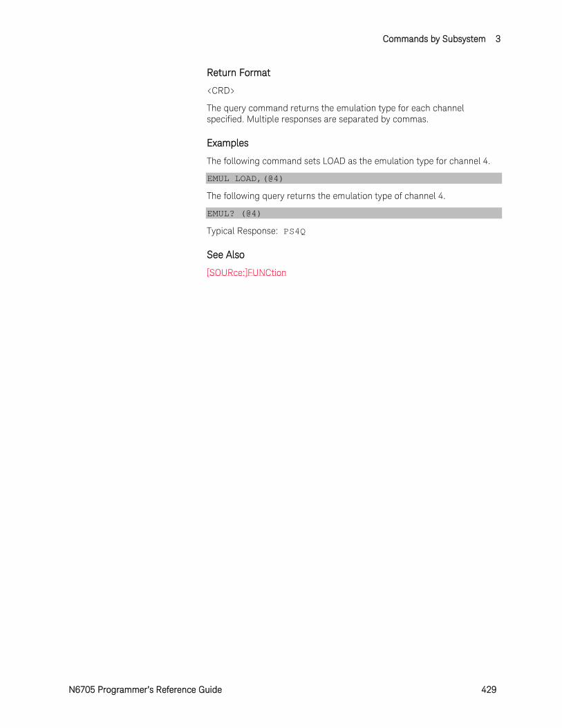
Commands by Subsystem 3
N6705 Programmer’s Reference Guide 429
Return Format
<CRD>
The query command returns the emulation type for each channel specified. Multiple responses are separated by commas.
Examples
The following command sets LOAD as the emulation type for channel 4.
EMUL LOAD,(@4)
The following query returns the emulation type of channel 4.
EMUL? (@4)
Typical Response: PS4Q
See Also
[SOURce:]FUNCtion
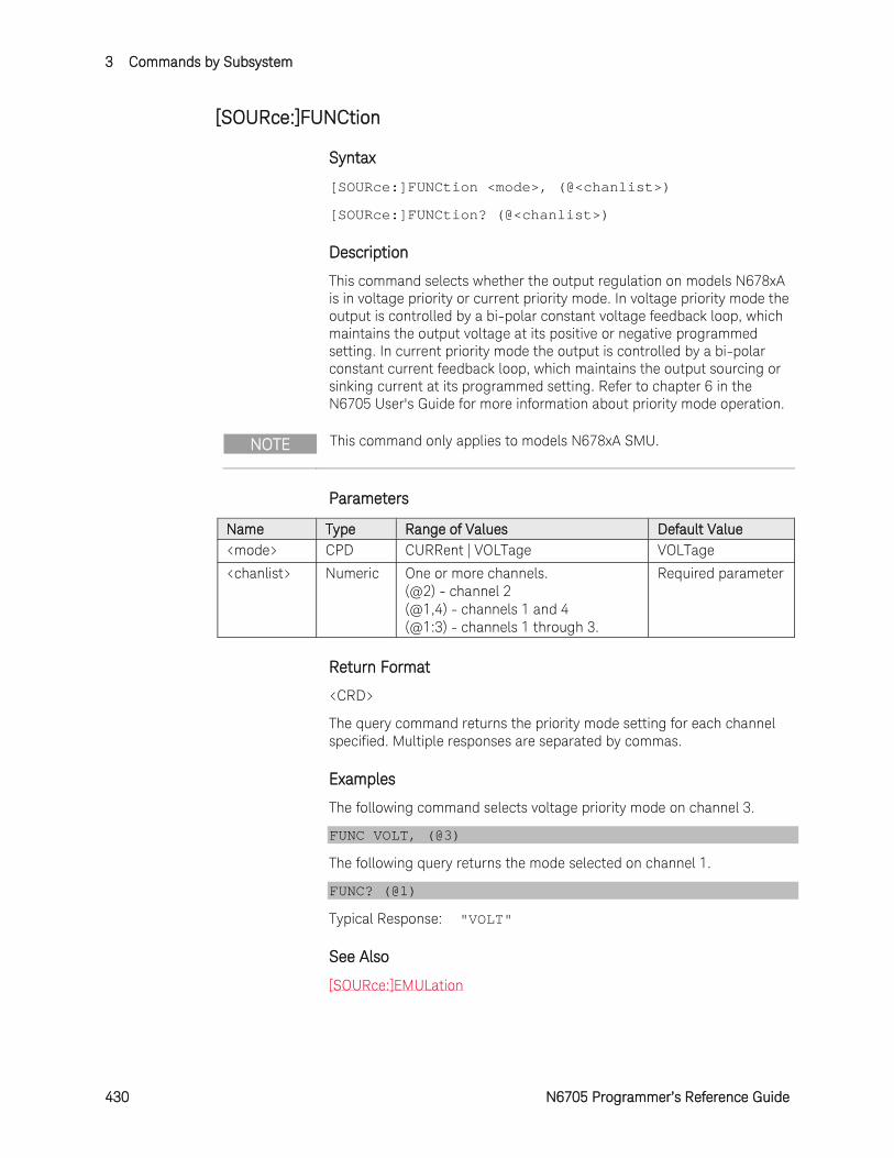
3 Commands by Subsystem
430 N6705 Programmer’s Reference Guide
[SOURce:]FUNCtion
Syntax
[SOURce:]FUNCtion <mode>, (@<chanlist>)
[SOURce:]FUNCtion? (@<chanlist>)
Description
This command selects whether the output regulation on models N678xA is in voltage priority or current priority mode. In voltage priority mode the output is controlled by a bi-polar constant voltage feedback loop, which maintains the output voltage at its positive or negative programmed setting. In current priority mode the output is controlled by a bi-polar constant current feedback loop, which maintains the output sourcing or sinking current at its programmed setting. Refer to chapter 6 in the N6705 User's Guide for more information about priority mode operation.
NOTE This command only applies to models N678xA SMU.
Parameters
Name Type Range of Values Default Value <mode> CPD CURRent | VOLTage VOLTage
<chanlist> Numeric One or more channels. (@2) - channel 2 (@1,4) - channels 1 and 4 (@1:3) - channels 1 through 3.
Required parameter
Return Format
<CRD>
The query command returns the priority mode setting for each channel specified. Multiple responses are separated by commas.
Examples
The following command selects voltage priority mode on channel 3.
FUNC VOLT, (@3)
The following query returns the mode selected on channel 1.
FUNC? (@1)
Typical Response: "VOLT"
See Also
[SOURce:]EMULation
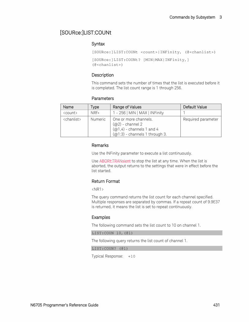
Commands by Subsystem 3
N6705 Programmer’s Reference Guide 431
[SOURce:]LIST:COUNt
Syntax
[SOURce:]LIST:COUNt <count>|INFinity, (@<chanlist>)
[SOURce:]LIST:COUNt? [MIN|MAX|INFinity,] (@<chanlist>)
Description
This command sets the number of times that the list is executed before it is completed. The list count range is 1 through 256.
Parameters
Name Type Range of Values Default Value <count> NRf+ 1 - 256 | MIN | MAX | INFinity 1
<chanlist> Numeric One or more channels. (@2) - channel 2 (@1,4) - channels 1 and 4 (@1:3) - channels 1 through 3.
Required parameter
Remarks
Use the INFinity parameter to execute a list continuously.
Use ABORt:TRANsient to stop the list at any time. When the list is aborted, the output returns to the settings that were in effect before the list started.
Return Format
<NR1>
The query command returns the list count for each channel specified. Multiple responses are separated by commas. If a repeat count of 9.9E37 is returned, it means the list is set to repeat continuously.
Examples
The following command sets the list count to 10 on channel 1.
LIST:COUN 10,(@1)
The following query returns the list count of channel 1.
LIST:COUN? (@1)
Typical Response: +10
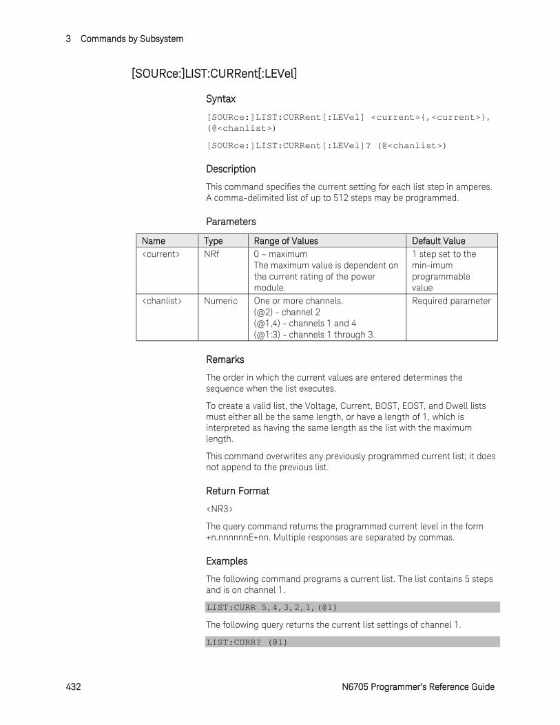
3 Commands by Subsystem
432 N6705 Programmer’s Reference Guide
[SOURce:]LIST:CURRent[:LEVel]
Syntax
[SOURce:]LIST:CURRent[:LEVel] <current>,<current>, (@<chanlist>)
[SOURce:]LIST:CURRent[:LEVel]? (@<chanlist>)
Description
This command specifies the current setting for each list step in amperes. A comma-delimited list of up to 512 steps may be programmed.
Parameters
Name Type Range of Values Default Value <current> NRf 0 – maximum
The maximum value is dependent on the current rating of the power module.
1 step set to the min-imum programmable value
<chanlist> Numeric One or more channels. (@2) - channel 2 (@1,4) - channels 1 and 4 (@1:3) - channels 1 through 3.
Required parameter
Remarks
The order in which the current values are entered determines the sequence when the list executes.
To create a valid list, the Voltage, Current, BOST, EOST, and Dwell lists must either all be the same length, or have a length of 1, which is interpreted as having the same length as the list with the maximum length.
This command overwrites any previously programmed current list; it does not append to the previous list.
Return Format
<NR3>
The query command returns the programmed current level in the form +n.nnnnnnE+nn. Multiple responses are separated by commas.
Examples
The following command programs a current list. The list contains 5 steps and is on channel 1.
LIST:CURR 5,4,3,2,1,(@1)
The following query returns the current list settings of channel 1.
LIST:CURR? (@1)
Commands by Subsystem 3
N6705 Programmer’s Reference Guide 433
Typical Response: +5.000000E+00,+4.000000E+00,+3.000000E+00,+2.000000E+00,+1.000000E+00
See Also
[SOURce:]LIST:DWELl
[SOURce:]LIST:VOLTage[:LEVel]

3 Commands by Subsystem
434 N6705 Programmer’s Reference Guide
[SOURce:]LIST:CURRent:POINts?
Syntax
[SOURce:]LIST:CURRent:POINts? (@<chanlist>)
Description
This query returns the number of points (steps) in the current list, not the point values.
Parameters
Name Type Range of Values Default Value <chanlist> Numeric One or more channels.
(@2) - channel 2 (@1,4) - channels 1 and 4 (@1:3) - channels 1 through 3.
Required parameter
Return Format
<NR1>
The number of points in the current list. Multiple responses are separated by commas.
Example
The following query returns the number of points in a current list for channel 1.
LIST:CURR:POIN? (@1)
Typical Response: +1
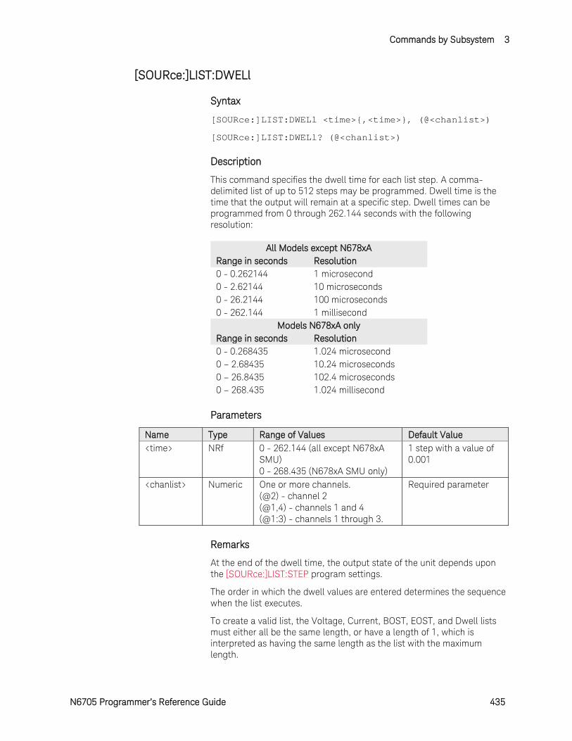
Commands by Subsystem 3
N6705 Programmer’s Reference Guide 435
[SOURce:]LIST:DWELl
Syntax
[SOURce:]LIST:DWELl <time>,<time>, (@<chanlist>)
[SOURce:]LIST:DWELl? (@<chanlist>)
Description
This command specifies the dwell time for each list step. A comma-delimited list of up to 512 steps may be programmed. Dwell time is the time that the output will remain at a specific step. Dwell times can be programmed from 0 through 262.144 seconds with the following resolution:
All Models except N678xA Range in seconds Resolution 0 - 0.262144 1 microsecond 0 - 2.62144 10 microseconds 0 - 26.2144 100 microseconds 0 - 262.144 1 millisecond
Models N678xA only Range in seconds Resolution 0 - 0.268435 1.024 microsecond 0 – 2.68435 10.24 microseconds 0 – 26.8435 102.4 microseconds 0 – 268.435 1.024 millisecond
Parameters
Name Type Range of Values Default Value <time> NRf 0 - 262.144 (all except N678xA
SMU) 0 - 268.435 (N678xA SMU only)
1 step with a value of 0.001
<chanlist> Numeric One or more channels. (@2) - channel 2 (@1,4) - channels 1 and 4 (@1:3) - channels 1 through 3.
Required parameter
Remarks
At the end of the dwell time, the output state of the unit depends upon the [SOURce:]LIST:STEP program settings.
The order in which the dwell values are entered determines the sequence when the list executes.
To create a valid list, the Voltage, Current, BOST, EOST, and Dwell lists must either all be the same length, or have a length of 1, which is interpreted as having the same length as the list with the maximum length.
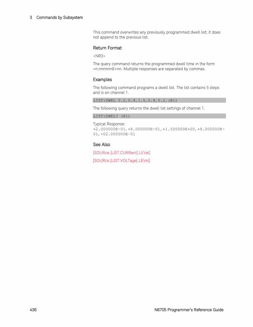
3 Commands by Subsystem
436 N6705 Programmer’s Reference Guide
This command overwrites any previously programmed dwell list; it does not append to the previous list.
Return Format
<NR3>
The query command returns the programmed dwell time in the form +n.nnnnnnE+nn. Multiple responses are separated by commas.
Examples
The following command programs a dwell list. The list contains 5 steps and is on channel 1.
LIST:DWEL 0.2,0.8,1.5,0.8,0.2,(@1)
The following query returns the dwell list settings of channel 1.
LIST:DWEL? (@1)
Typical Response: +2.000000E-01,+8.000000E-01,+1.500000E+00,+8.000000E-01,+02.000000E-01
See Also
[SOURce:]LIST:CURRent[:LEVel]
[SOURce:]LIST:VOLTage[:LEVel]
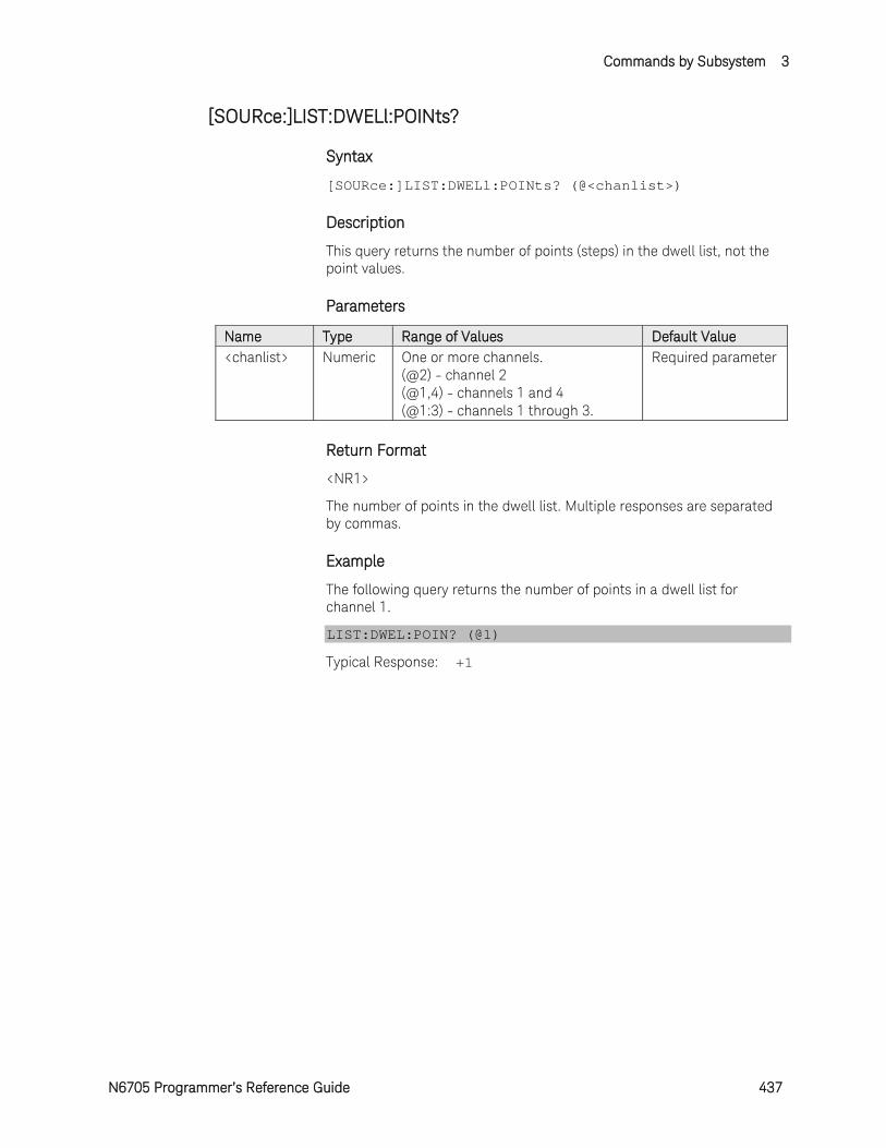
Commands by Subsystem 3
N6705 Programmer’s Reference Guide 437
[SOURce:]LIST:DWELl:POINts?
Syntax
[SOURce:]LIST:DWELl:POINts? (@<chanlist>)
Description
This query returns the number of points (steps) in the dwell list, not the point values.
Parameters
Name Type Range of Values Default Value <chanlist> Numeric One or more channels.
(@2) - channel 2 (@1,4) - channels 1 and 4 (@1:3) - channels 1 through 3.
Required parameter
Return Format
<NR1>
The number of points in the dwell list. Multiple responses are separated by commas.
Example
The following query returns the number of points in a dwell list for channel 1.
LIST:DWEL:POIN? (@1)
Typical Response: +1
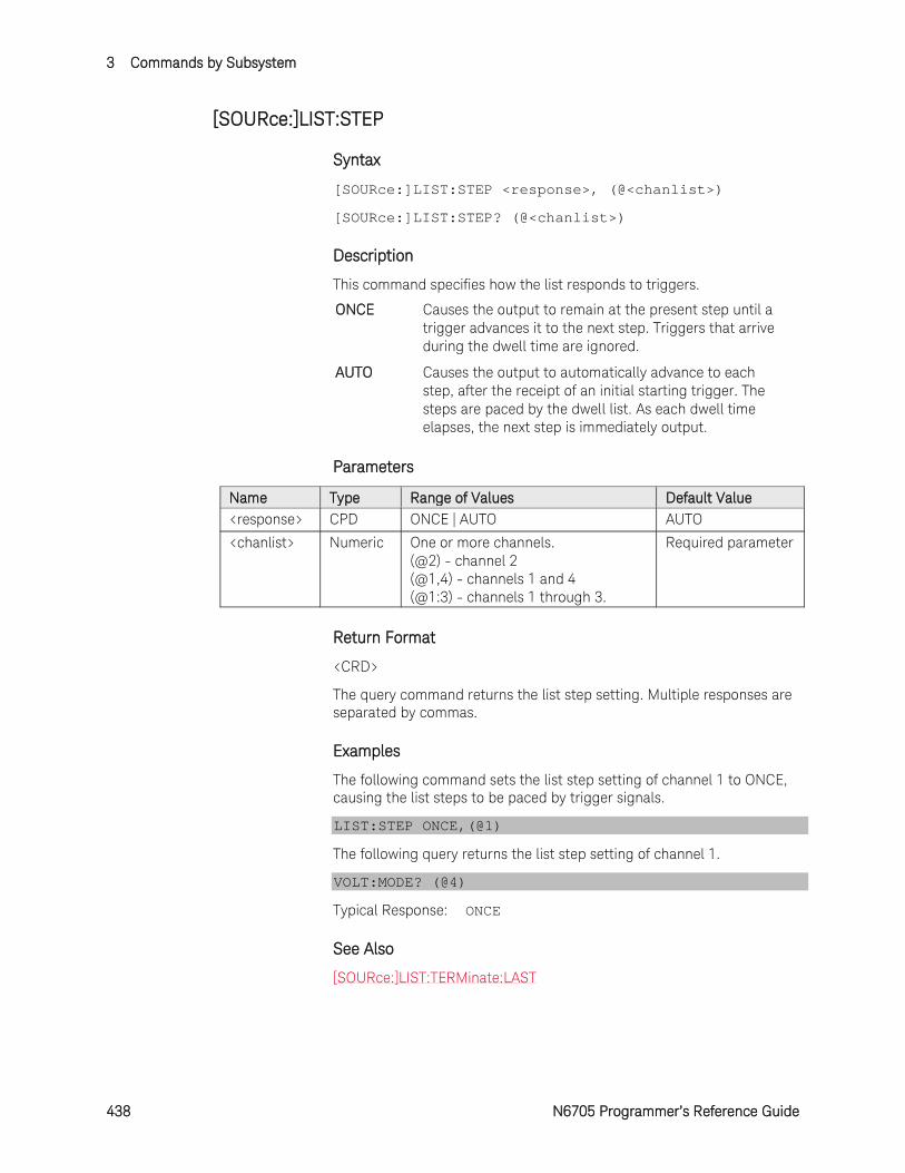
3 Commands by Subsystem
438 N6705 Programmer’s Reference Guide
[SOURce:]LIST:STEP
Syntax
[SOURce:]LIST:STEP <response>, (@<chanlist>)
[SOURce:]LIST:STEP? (@<chanlist>)
Description
This command specifies how the list responds to triggers.
ONCE Causes the output to remain at the present step until a trigger advances it to the next step. Triggers that arrive during the dwell time are ignored.
AUTO Causes the output to automatically advance to each step, after the receipt of an initial starting trigger. The steps are paced by the dwell list. As each dwell time elapses, the next step is immediately output.
Parameters
Name Type Range of Values Default Value <response> CPD ONCE | AUTO AUTO
<chanlist> Numeric One or more channels. (@2) - channel 2 (@1,4) - channels 1 and 4 (@1:3) - channels 1 through 3.
Required parameter
Return Format
<CRD>
The query command returns the list step setting. Multiple responses are separated by commas.
Examples
The following command sets the list step setting of channel 1 to ONCE, causing the list steps to be paced by trigger signals.
LIST:STEP ONCE,(@1)
The following query returns the list step setting of channel 1.
VOLT:MODE? (@4)
Typical Response: ONCE
See Also
[SOURce:]LIST:TERMinate:LAST

Commands by Subsystem 3
N6705 Programmer’s Reference Guide 439
[SOURce:]LIST:TERMinate:LAST
Syntax
[SOURce:]LIST:TERMinate:LAST <Bool>, (@<chanlist>)
[SOURce:]LIST:TERMinate:LAST? (@<chanlist>)
Description
This command determines the output value when the list terminates. The state is either ON (1) or OFF (0).
When ON, the output voltage or current remains at the value of the last list step. The value of the last voltage or current list step becomes the IMMediate value when the list completes.
When OFF, and also when the list is aborted, the output returns to the settings that were in effect before the list started.
Parameters
Name Type Range of Values Default Value <Bool> Boolean OFF | 0 | ON | 1 OFF
<chanlist> Numeric One or more channels. (@2) - channel 2 (@1,4) - channels 1 and 4 (@1:3) - channels 1 through 3.
Required parameter
Return Format
<NR1>
The query command returns 0 if the output returns to the settings that were in effect before the list started, and 1 if the output voltage or current remains at the value of the last list step.
Examples
The following command sets the list to terminate with the output voltage or current remaining at the value of the last list step on channel 2.
LIST:TERM:LAST ON,(@2)
The following query returns the list terminate setting of channel 1.
LIST:TERM:LAST? (@1)
Typical Response: 0
See Also
[SOURce:]LIST:STEP
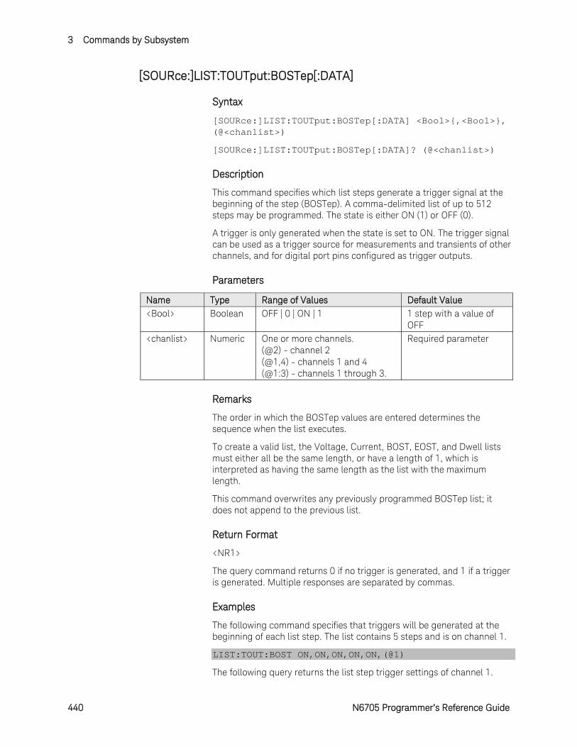
3 Commands by Subsystem
440 N6705 Programmer’s Reference Guide
[SOURce:]LIST:TOUTput:BOSTep[:DATA]
Syntax
[SOURce:]LIST:TOUTput:BOSTep[:DATA] <Bool>,<Bool>, (@<chanlist>)
[SOURce:]LIST:TOUTput:BOSTep[:DATA]? (@<chanlist>)
Description
This command specifies which list steps generate a trigger signal at the beginning of the step (BOSTep). A comma-delimited list of up to 512 steps may be programmed. The state is either ON (1) or OFF (0).
A trigger is only generated when the state is set to ON. The trigger signal can be used as a trigger source for measurements and transients of other channels, and for digital port pins configured as trigger outputs.
Parameters
Name Type Range of Values Default Value <Bool> Boolean OFF | 0 | ON | 1 1 step with a value of
OFF <chanlist> Numeric One or more channels.
(@2) - channel 2 (@1,4) - channels 1 and 4 (@1:3) - channels 1 through 3.
Required parameter
Remarks
The order in which the BOSTep values are entered determines the sequence when the list executes.
To create a valid list, the Voltage, Current, BOST, EOST, and Dwell lists must either all be the same length, or have a length of 1, which is interpreted as having the same length as the list with the maximum length.
This command overwrites any previously programmed BOSTep list; it does not append to the previous list.
Return Format
<NR1>
The query command returns 0 if no trigger is generated, and 1 if a trigger is generated. Multiple responses are separated by commas.
Examples
The following command specifies that triggers will be generated at the beginning of each list step. The list contains 5 steps and is on channel 1.
LIST:TOUT:BOST ON,ON,ON,ON,ON,(@1)
The following query returns the list step trigger settings of channel 1.

Commands by Subsystem 3
N6705 Programmer’s Reference Guide 441
LIST:TOUT:BOST? (@1)
Typical Response: 1,1,1,1,1
See Also
[SOURce:]LIST:TOUTput:EOSTep[:DATA]
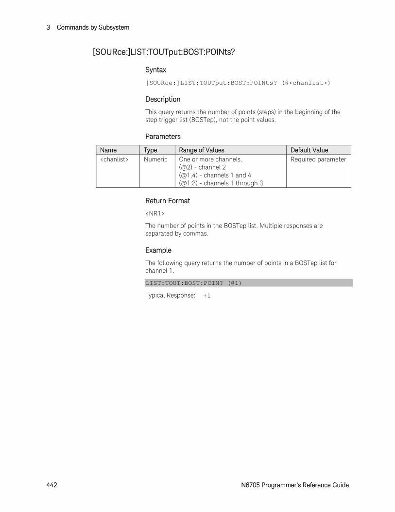
3 Commands by Subsystem
442 N6705 Programmer’s Reference Guide
[SOURce:]LIST:TOUTput:BOST:POINts?
Syntax
[SOURce:]LIST:TOUTput:BOST:POINts? (@<chanlist>)
Description
This query returns the number of points (steps) in the beginning of the step trigger list (BOSTep), not the point values.
Parameters
Name Type Range of Values Default Value <chanlist> Numeric One or more channels.
(@2) - channel 2 (@1,4) - channels 1 and 4 (@1:3) - channels 1 through 3.
Required parameter
Return Format
<NR1>
The number of points in the BOSTep list. Multiple responses are separated by commas.
Example
The following query returns the number of points in a BOSTep list for channel 1.
LIST:TOUT:BOST:POIN? (@1)
Typical Response: +1
Commands by Subsystem 3
N6705 Programmer’s Reference Guide 443
[SOURce:]LIST:TOUTput:EOSTep[:DATA]
Syntax
[SOURce:]LIST:TOUTput:EOSTep[:DATA] <Bool>,<Bool>, (@<chanlist>)
[SOURce:]LIST:TOUTput:EOSTep[:DATA]? (@<chanlist>)
Description
This command specifies which list steps generate a trigger signal at the end of the step (EOSTep). A comma-delimited list of up to 512 steps may be programmed. The state is either ON (1) or OFF (0).
A trigger is only generated when the state is set to ON. The trigger signal can be used as a trigger source for measurements and transients of other channels, and for digital port pins configured as trigger outputs.
Parameters
Name Type Range of Values Default Value <Bool> Boolean OFF | 0 | ON | 1 1 step with a value of
OFF <chanlist> Numeric One or more channels.
(@2) - channel 2 (@1,4) - channels 1 and 4 (@1:3) - channels 1 through 3.
Required parameter
Remarks
The order in which the EOSTep values are entered determines the sequence when the list executes.
To create a valid list, the Voltage, Current, BOST, EOST, and Dwell lists must either all be the same length, or have a length of 1, which is interpreted as having the same length as the list with the maximum length.
This command overwrites any previously programmed EOSTep list; it does not append to the previous list.
Return Format
<NR1>
The query command returns 0 if no trigger is generated, and 1 if a trigger is generated. Multiple responses are separated by commas.
Examples
The following command specifies that triggers will be generated at the end of each list step. The list contains 5 steps and is on channel 1.
LIST:TOUT:EOST ON,ON,ON,ON,ON,(@1)
The following query returns the list step trigger settings of channel 1.
3 Commands by Subsystem
444 N6705 Programmer’s Reference Guide
LIST:TOUT:EOST? (@1)
Typical Response: 1,1,1,1,1
See Also
[SOURce:]LIST:TOUTput:BOSTep[:DATA]
Commands by Subsystem 3
N6705 Programmer’s Reference Guide 445
[SOURce:]LIST:TOUTput:EOST:POINts?
Syntax
[SOURce:]LIST:TOUTput:EOST:POINts? (@<chanlist>)
Description
This query returns the number of points (steps) in the end of the step trigger list (EOSTep), not the point values.
Parameters
Name Type Range of Values Default Value <chanlist> Numeric One or more channels.
(@2) - channel 2 (@1,4) - channels 1 and 4 (@1:3) - channels 1 through 3.
Required parameter
Return Format
<NR1>
The number of points in the EOSTep list. Multiple responses are separated by commas.
Example
The following query returns the number of points in a EOSTep list for channel 1.
LIST:TOUT:EOST:POIN? (@1)
Typical Response: +1

3 Commands by Subsystem
446 N6705 Programmer’s Reference Guide
[SOURce:]LIST:VOLTage[:LEVel]
Syntax
[SOURce:]LIST:VOLTage[:LEVel] <voltage>,<voltage>, (@<chanlist>)
[SOURce:]LIST:VOLTage[:LEVel]? (@<chanlist>)
Description
This command specifies the voltage setting for each list step in volts. A comma-delimited list of up to 512 steps may be programmed.
Parameters
Name Type Range of Values Default Value <voltage> NRf 0 – maximum
The maximum value is dependent on the voltage rating of the power module.
1 step set to the min-imum programmable value
<chanlist> Numeric One or more channels. (@2) - channel 2 (@1,4) - channels 1 and 4 (@1:3) - channels 1 through 3.
Required parameter
Remarks
The order in which the voltage values are entered determines the sequence when the list executes.
To create a valid list, the Voltage, Current, BOST, EOST, and Dwell lists must either all be the same length, or have a length of 1, which is interpreted as having the same length as the list with the maximum length.
This command overwrites any previously programmed voltage list; it does not append to the previous list.
Return Format
<NR3>
The query command returns the programmed voltage level in the form +n.nnnnnnE+nn. Multiple responses are separated by commas.
Examples
The following command programs a voltage list. The list contains 5 steps and is on channel 1.
LIST:VOLT 10,20,30,40,50,(@1)
The following query returns the voltage list settings of channel 1.
LIST:VOLT? (@1)

Commands by Subsystem 3
N6705 Programmer’s Reference Guide 447
Typical Response: +1.000000E+01,+2.000000E+01,+3.000000E+01,+4.000000E+01,+5.000000E+01
See Also
[SOURce:]LIST:DWELl
[SOURce:]LIST:CURRent[:LEVel]
3 Commands by Subsystem
448 N6705 Programmer’s Reference Guide
[SOURce:]LIST:VOLTage:POINts?
Syntax
[SOURce:]LIST:VOLTage:POINts? (@<chanlist>)
Description
This query returns the number of points (steps) in the voltage list, not the point values.
Parameters
Name Type Range of Values Default Value <chanlist> Numeric One or more channels.
(@2) - channel 2 (@1,4) - channels 1 and 4 (@1:3) - channels 1 through 3.
Required parameter
Return Format
<NR1>
The number of points in the voltage list. Multiple responses are separated by commas.
Example
The following query returns the number of points in a voltage list for channel 1.
LIST:VOLT:POIN? (@1)
Typical Response: +1
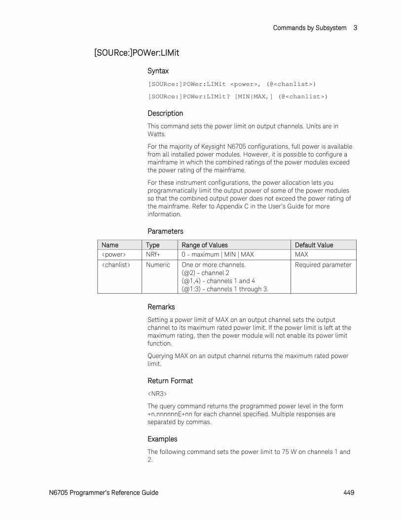
Commands by Subsystem 3
N6705 Programmer’s Reference Guide 449
[SOURce:]POWer:LIMit
Syntax
[SOURce:]POWer:LIMit <power>, (@<chanlist>)
[SOURce:]POWer:LIMit? [MIN|MAX,] (@<chanlist>)
Description
This command sets the power limit on output channels. Units are in Watts.
For the majority of Keysight N6705 configurations, full power is available from all installed power modules. However, it is possible to configure a mainframe in which the combined ratings of the power modules exceed the power rating of the mainframe.
For these instrument configurations, the power allocation lets you programmatically limit the output power of some of the power modules so that the combined output power does not exceed the power rating of the mainframe. Refer to Appendix C in the User’s Guide for more information.
Parameters
Name Type Range of Values Default Value <power> NRf+ 0 - maximum | MIN | MAX MAX
<chanlist> Numeric One or more channels. (@2) - channel 2 (@1,4) - channels 1 and 4 (@1:3) - channels 1 through 3.
Required parameter
Remarks
Setting a power limit of MAX on an output channel sets the output channel to its maximum rated power limit. If the power limit is left at the maximum rating, then the power module will not enable its power limit function.
Querying MAX on an output channel returns the maximum rated power limit.
Return Format
<NR3>
The query command returns the programmed power level in the form +n.nnnnnnE+nn for each channel specified. Multiple responses are separated by commas.
Examples
The following command sets the power limit to 75 W on channels 1 and 2.

3 Commands by Subsystem
450 N6705 Programmer’s Reference Guide
POW:LIM 75,(@1,2)
The following query returns the programmed power limit on channels 1 and 2.
POW:LIM? (@1,2)
Typical Response: +7.500000E+01,+7.500000E+01
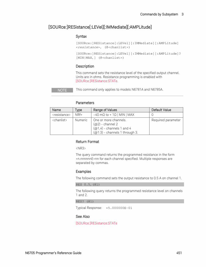
Commands by Subsystem 3
N6705 Programmer’s Reference Guide 451
[SOURce:]RESistance[:LEVel][:IMMediate][:AMPLitude]
Syntax
[SOURce:]RESistance[:LEVel][:IMMediate][:AMPLitude] <resistance>, (@<chanlist>)
[SOURce:]RESistance[:LEVel][:IMMediate][:AMPLitude]? [MIN|MAX,] (@<chanlist>)
Description
This command sets the resistance level of the specified output channel. Units are in ohms. Resistance programming is enabled with [SOURce:]RESistance:STATe.
NOTE This command only applies to models N6781A and N6785A.
Parameters
Name Type Range of Values Default Value <resistance> NRf+ –40 mΩ to + 1Ω | MIN | MAX 0
<chanlist> Numeric One or more channels. (@2) - channel 2 (@1,4) - channels 1 and 4 (@1:3) - channels 1 through 3.
Required parameter
Return Format
<NR3>
The query command returns the programmed resistance in the form +n.nnnnnnE+nn for each channel specified. Multiple responses are separated by commas.
Examples
The following command sets the output resistance to 0.5 A on channel 1.
RES 0.5,(@1)
The following query returns the programmed resistance level on channels 1 and 2.
RES? (@1)
Typical Response: +5.000000E-01
See Also
[SOURce:]RESistance:STATe
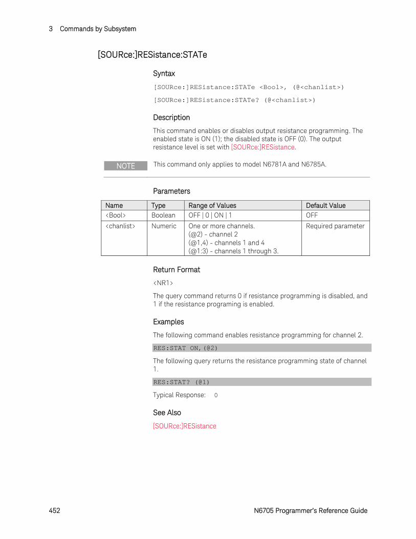
3 Commands by Subsystem
452 N6705 Programmer’s Reference Guide
[SOURce:]RESistance:STATe
Syntax
[SOURce:]RESistance:STATe <Bool>, (@<chanlist>)
[SOURce:]RESistance:STATe? (@<chanlist>)
Description
This command enables or disables output resistance programming. The enabled state is ON (1); the disabled state is OFF (0). The output resistance level is set with [SOURce:]RESistance.
NOTE This command only applies to model N6781A and N6785A.
Parameters
Name Type Range of Values Default Value <Bool> Boolean OFF | 0 | ON | 1 OFF
<chanlist> Numeric One or more channels. (@2) - channel 2 (@1,4) - channels 1 and 4 (@1:3) - channels 1 through 3.
Required parameter
Return Format
<NR1>
The query command returns 0 if resistance programming is disabled, and 1 if the resistance programing is enabled.
Examples
The following command enables resistance programming for channel 2.
RES:STAT ON,(@2)
The following query returns the resistance programming state of channel 1.
RES:STAT? (@1)
Typical Response: 0
See Also
[SOURce:]RESistance
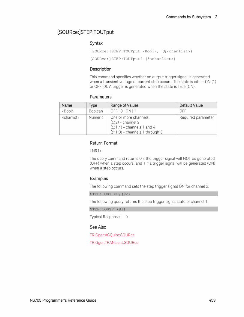
Commands by Subsystem 3
N6705 Programmer’s Reference Guide 453
[SOURce:]STEP:TOUTput
Syntax
[SOURce:]STEP:TOUTput <Bool>, (@<chanlist>)
[SOURce:]STEP:TOUTput? (@<chanlist>)
Description
This command specifies whether an output trigger signal is generated when a transient voltage or current step occurs. The state is either ON (1) or OFF (0). A trigger is generated when the state is True (ON).
Parameters
Name Type Range of Values Default Value <Bool> Boolean OFF | 0 | ON | 1 OFF
<chanlist> Numeric One or more channels. (@2) - channel 2 (@1,4) - channels 1 and 4 (@1:3) - channels 1 through 3.
Required parameter
Return Format
<NR1>
The query command returns 0 if the trigger signal will NOT be generated (OFF) when a step occurs, and 1 if a trigger signal will be generated (ON) when a step occurs.
Examples
The following command sets the step trigger signal ON for channel 2.
STEP:TOUT ON,(@2)
The following query returns the step trigger signal state of channel 1.
STEP:TOUT? (@1)
Typical Response: 0
See Also
TRIGger:ACQuire:SOURce
TRIGger:TRANsient:SOURce
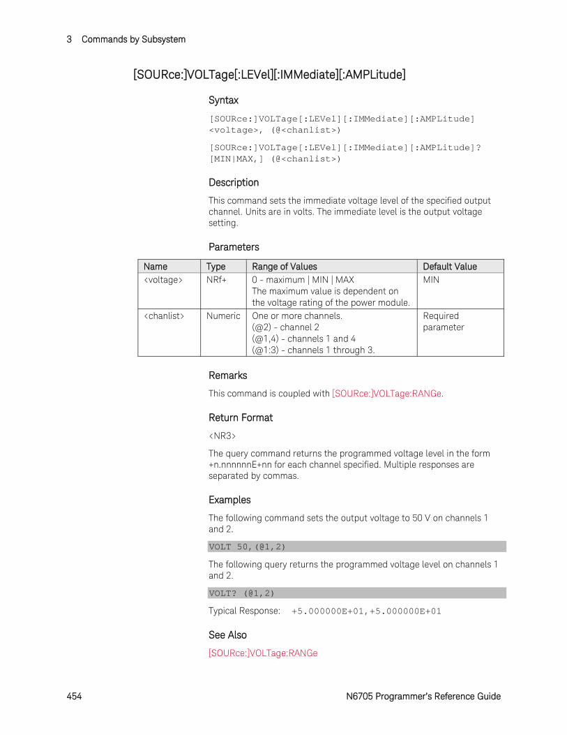
3 Commands by Subsystem
454 N6705 Programmer’s Reference Guide
[SOURce:]VOLTage[:LEVel][:IMMediate][:AMPLitude]
Syntax
[SOURce:]VOLTage[:LEVel][:IMMediate][:AMPLitude] <voltage>, (@<chanlist>)
[SOURce:]VOLTage[:LEVel][:IMMediate][:AMPLitude]? [MIN|MAX,] (@<chanlist>)
Description
This command sets the immediate voltage level of the specified output channel. Units are in volts. The immediate level is the output voltage setting.
Parameters
Name Type Range of Values Default Value <voltage> NRf+ 0 - maximum | MIN | MAX
The maximum value is dependent on the voltage rating of the power module.
MIN
<chanlist> Numeric One or more channels. (@2) - channel 2 (@1,4) - channels 1 and 4 (@1:3) - channels 1 through 3.
Required parameter
Remarks
This command is coupled with [SOURce:]VOLTage:RANGe.
Return Format
<NR3>
The query command returns the programmed voltage level in the form +n.nnnnnnE+nn for each channel specified. Multiple responses are separated by commas.
Examples
The following command sets the output voltage to 50 V on channels 1 and 2.
VOLT 50,(@1,2)
The following query returns the programmed voltage level on channels 1 and 2.
VOLT? (@1,2)
Typical Response: +5.000000E+01,+5.000000E+01
See Also
[SOURce:]VOLTage:RANGe
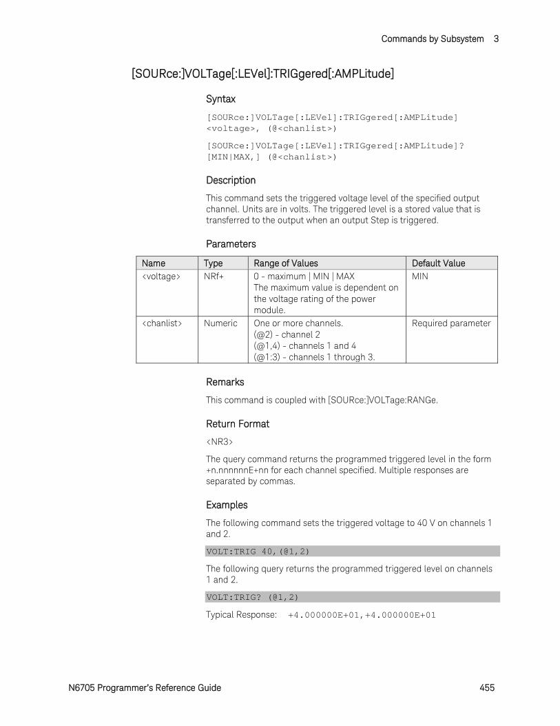
Commands by Subsystem 3
N6705 Programmer’s Reference Guide 455
[SOURce:]VOLTage[:LEVel]:TRIGgered[:AMPLitude]
Syntax
[SOURce:]VOLTage[:LEVel]:TRIGgered[:AMPLitude] <voltage>, (@<chanlist>)
[SOURce:]VOLTage[:LEVel]:TRIGgered[:AMPLitude]? [MIN|MAX,] (@<chanlist>)
Description
This command sets the triggered voltage level of the specified output channel. Units are in volts. The triggered level is a stored value that is transferred to the output when an output Step is triggered.
Parameters
Name Type Range of Values Default Value <voltage> NRf+ 0 - maximum | MIN | MAX
The maximum value is dependent on the voltage rating of the power module.
MIN
<chanlist> Numeric One or more channels. (@2) - channel 2 (@1,4) - channels 1 and 4 (@1:3) - channels 1 through 3.
Required parameter
Remarks
This command is coupled with [SOURce:]VOLTage:RANGe.
Return Format
<NR3>
The query command returns the programmed triggered level in the form +n.nnnnnnE+nn for each channel specified. Multiple responses are separated by commas.
Examples
The following command sets the triggered voltage to 40 V on channels 1 and 2.
VOLT:TRIG 40,(@1,2)
The following query returns the programmed triggered level on channels 1 and 2.
VOLT:TRIG? (@1,2)
Typical Response: +4.000000E+01,+4.000000E+01
3 Commands by Subsystem
456 N6705 Programmer’s Reference Guide
See Also
[SOURce:]VOLTage[:LEVel][:IMMediate]
[SOURce:]VOLTage:MODE
TRIGger:TRANsient[:IMMediate]
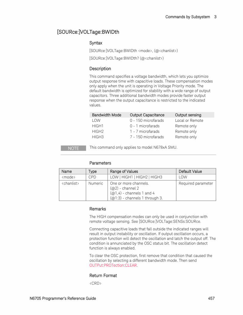
Commands by Subsystem 3
N6705 Programmer’s Reference Guide 457
[SOURce:]VOLTage:BWIDth
Syntax
[SOURce:]VOLTage:BWIDth <mode>, (@<chanlist>)
[SOURce:]VOLTage:BWIDth? (@<chanlist>)
Description
This command specifies a voltage bandwidth, which lets you optimize output response time with capacitive loads. These compensation modes only apply when the unit is operating in Voltage Priority mode. The default bandwidth is optimized for stability with a wide range of output capacitors. Three additional bandwidth modes provide faster output response when the output capacitance is restricted to the indicated values.
Bandwidth Mode Output Capacitance Output sensing LOW 0 - 150 microfarads Local or Remote HIGH1 0 - 1 microfarads Remote only HIGH2 1 - 7 microfarads Remote only HIGH3 7 - 150 microfarads Remote only
NOTE This command only applies to model N678xA SMU.
Parameters
Name Type Range of Values Default Value <mode> CPD LOW | HIGH1 | HIGH2 | HIGH3 LOW
<chanlist> Numeric One or more channels. (@2) - channel 2 (@1,4) - channels 1 and 4 (@1:3) - channels 1 through 3.
Required parameter
Remarks
The HIGH compensation modes can only be used in conjunction with remote voltage sensing. See [SOURce:]VOLTage:SENSs:SOURce.
Connecting capacitive loads that fall outside the indicated ranges will result in output instability or oscillation. If output oscillation occurs, a protection function will detect the oscillation and latch the output off. The condition is annunciated by the OSC status bit. The oscillation detect function is always enabled.
To clear the OSC protection, first remove that condition that caused the oscillation by selecting a different bandwidth mode. Then send OUTPut:PROTection:CLEAR.
Return Format
<CRD>
3 Commands by Subsystem
458 N6705 Programmer’s Reference Guide
The query command returns the bandwidth selection for each channel specified. Multiple responses are separated by commas.
Examples
The following command sets a bandwidth selection of 1 - 7 microfarads for channel 4.
VOLT:BWID HIGH2,(@4)
The following query returns the bandwidth selection of channel 1.
VOLT:BWID? (@1)
Typical Response: LOW
See Also
OUTPut:PROTection:OSCillation
Commands by Subsystem 3
N6705 Programmer’s Reference Guide 459
[SOURce:]VOLTage:LIMit:COUPle
Syntax
[SOURce:]VOLTage:LIMit:COUPle <Bool>, (@<chanlist>)
[SOURce:]VOLTage:LIMit:COUPle? (@<chanlist>)
Description
This command sets the voltage limit tracking state. The enabled state is On (1); the disabled state is Off (0). If limit tracking is enabled, The negative voltage limit tracks the positive voltage limit setting. The [SOURce:]VOLTage:LIMit command sets the value of the positive and negative voltage limits.
NOTE This command only applies to model N6784A.
Parameters
Name Type Range of Values Default Value <Bool> Boolean OFF | 0 | ON | 1 OFF
<chanlist> Numeric One or more channels. (@2) - channel 2 (@1,4) - channels 1 and 4 (@1:3) - channels 1 through 3.
Required parameter
Return Format
<NR1>
The query command returns 1 if the voltage limit coupling is enabled, and 0 if the voltage limit coupling is disabled.
Examples
The following command sets the voltage limit coupling on for channel 4.
VOLT:LIM:COUP ON,(@4)
The following query returns the voltage limit coupling state for channel 1.
VOLT:LIM:COUP? (@1)
Typical Response: 0
See Also
[SOURce:]VOLTage:LIMit
[SOURce:]VOLTage:LIMit:NEGative
3 Commands by Subsystem
460 N6705 Programmer’s Reference Guide
[SOURce:]VOLTage:LIMit[:POSitive][:IMMediate][:AMPLitude]
Syntax
[SOURce:]VOLTage:LIMit[:POSitive][:IMMediate] [:AMPLitude] <limit>, (@<chanlist>)
[SOURce:]VOLTage:LIMit[:POSitive][:IMMediate] [:AMPLitude]? [MIN|MAX,] (@<chanlist>)
Description
This command sets the positive voltage limit of the specified output channel. Units are in volts. If [SOURce:]VOLTage:LIMit:COUPle is enabled, this command also sets the value of the negative voltage limit. Refer to chapter 6 in the N6705 User's Guide under "Current Priority" for more information about voltage limit operation.
NOTE This command only applies to model N678xA SMU.
Parameters
Name Type Range of Values Default Value <limit> NRf+ 0 - 20.4 | MIN | MAX MAX (of selected
range) <chanlist> Numeric One or more channels.
(@2) - channel 2 (@1,4) - channels 1 and 4 (@1:3) - channels 1 through 3.
Required parameter
Return Format
<NR3>
The query command returns the voltage limit in the form +n.nnnnnnE+nn for each channel specified. Multiple responses are separated by commas.
Examples
The following command sets the voltage limit to 20 V on channels 1 and 2.
VOLT:LIM 20,(@1,2)
The following query returns the voltage limit on channels 1 and 2.
VOLT:LIM? (@1,2)
Typical Response: +2.000000E+01;+2.000000E+01
See Also
[SOURce:]VOLTage:LIMit:COUPle
[SOURce:]VOLTage:LIMit:NEGative
Commands by Subsystem 3
N6705 Programmer’s Reference Guide 461
[SOURce:]VOLTage:LIMit:NEGative[:IMMediate][:AMPLitude]
Syntax
[SOURce:]VOLTage:LIMit:NEGative[:IMMediate] [:AMPLitude] <limit>, (@<chanlist>)
[SOURce:]VOLTage:LIMit:NEGative[:IMMediate] [:AMPLitude]? [MIN|MAX,] (@<chanlist>)
Description
This command sets the negative voltage limit of the specified output channel. Units are in volts. If [SOURce:]VOLTage:LIMit:COUPle is enabled, this command also sets the value of the positive voltage limit. Refer to chapter 6 in the N6705 User's Guide under "Current Priority" for more information about voltage limit operation.
NOTE This command only applies to model N6784A.
Parameters
Name Type Range of Values Default Value <limit> NRf+ -20.4 to 0 | MIN | MAX MIN (of selected
range) <chanlist> Numeric One or more channels.
(@2) - channel 2 (@1,4) - channels 1 and 4 (@1:3) - channels 1 through 3.
Required parameter
Remarks
MIN refers to the most negative value of the range. MAX refers to the least negative value of the range.
Return Format
<NR3>
The query command returns the negative voltage limit in the form +n.nnnnnnE+nn for each channel specified. Multiple responses are separated by commas.
Examples
The following command sets the negative voltage limit to -19 V on channels 1 and 3.
VOLT:LIM:NEG -19,(@1,3)
The following query returns the negative voltage limit on channels 1 and 2.
3 Commands by Subsystem
462 N6705 Programmer’s Reference Guide
VOLT:LIM:NEG? (@1,3)
Typical Response: -1.900000E+01,-1.900000E+01
See Also
[SOURce:]VOLTage:LIMit:COUPle
[SOURce:]VOLTage:LIMit
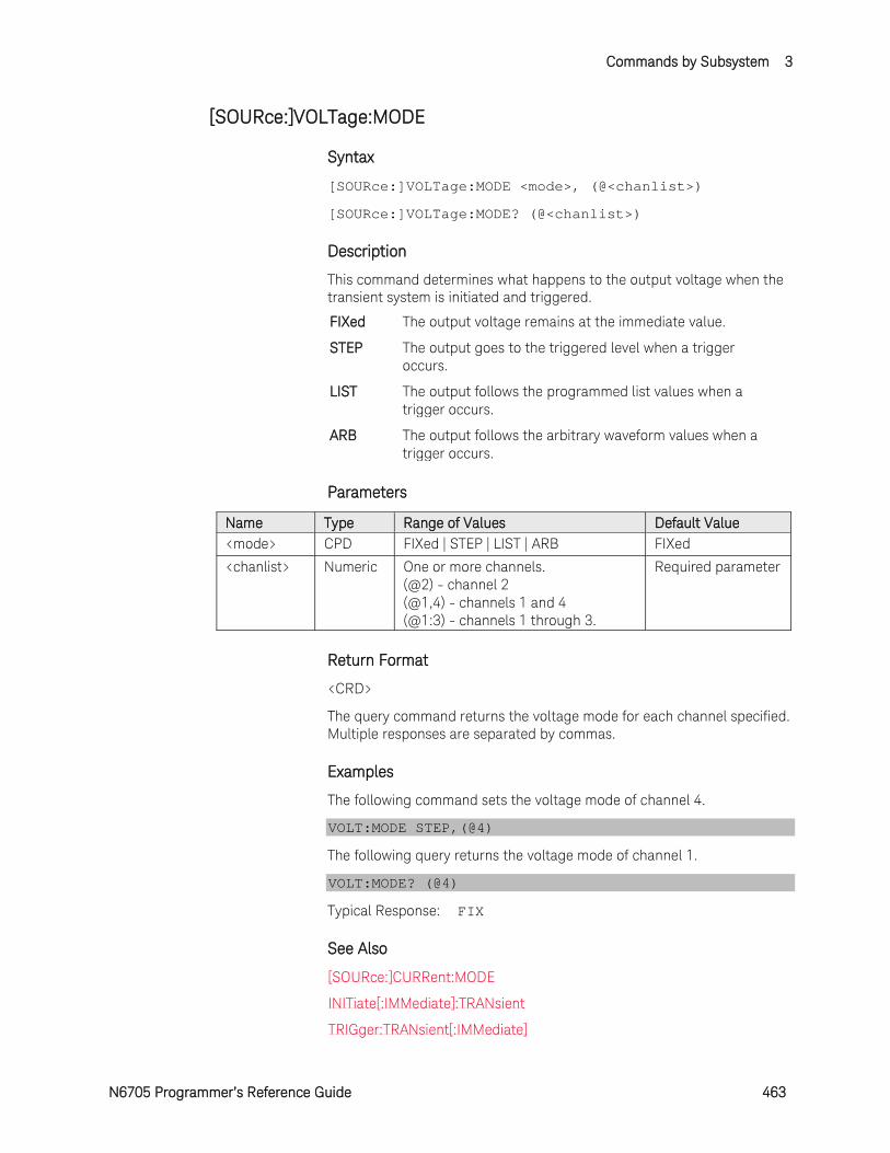
Commands by Subsystem 3
N6705 Programmer’s Reference Guide 463
[SOURce:]VOLTage:MODE
Syntax
[SOURce:]VOLTage:MODE <mode>, (@<chanlist>)
[SOURce:]VOLTage:MODE? (@<chanlist>)
Description
This command determines what happens to the output voltage when the transient system is initiated and triggered.
FIXed The output voltage remains at the immediate value.
STEP The output goes to the triggered level when a trigger occurs.
LIST The output follows the programmed list values when a trigger occurs.
ARB The output follows the arbitrary waveform values when a trigger occurs.
Parameters
Name Type Range of Values Default Value <mode> CPD FIXed | STEP | LIST | ARB FIXed
<chanlist> Numeric One or more channels. (@2) - channel 2 (@1,4) - channels 1 and 4 (@1:3) - channels 1 through 3.
Required parameter
Return Format
<CRD>
The query command returns the voltage mode for each channel specified. Multiple responses are separated by commas.
Examples
The following command sets the voltage mode of channel 4.
VOLT:MODE STEP,(@4)
The following query returns the voltage mode of channel 1.
VOLT:MODE? (@4)
Typical Response: FIX
See Also
[SOURce:]CURRent:MODE
INITiate[:IMMediate]:TRANsient
TRIGger:TRANsient[:IMMediate]
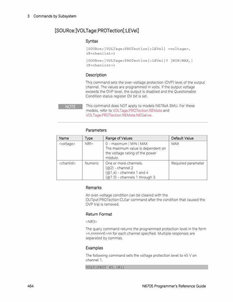
3 Commands by Subsystem
464 N6705 Programmer’s Reference Guide
[SOURce:]VOLTage:PROTection[:LEVel]
Syntax
[SOURce:]VOLTage:PROTection[:LEVel] <voltage>, (@<chanlist>)
[SOURce:]VOLTage:PROTection[:LEVel]? [MIN|MAX,] (@<chanlist>)
Description
This command sets the over-voltage protection (OVP) level of the output channel. The values are programmed in volts. If the output voltage exceeds the OVP level, the output is disabled and the Questionable Condition status register OV bit is set.
NOTE This command does NOT apply to models N678xA SMU. For these models, refer to VOLTage:PROTection:REMote and VOLTage:PROTection:REMote:NEGative.
Parameters
Name Type Range of Values Default Value <voltage> NRf+ 0 - maximum | MIN | MAX
The maximum value is dependent on the voltage rating of the power module.
MAX
<chanlist> Numeric One or more channels. (@2) - channel 2 (@1,4) - channels 1 and 4 (@1:3) - channels 1 through 3.
Required parameter
Remarks
An over-voltage condition can be cleared with the OUTput:PROTection:CLEar command after the condition that caused the OVP trip is removed.
Return Format
<NR3>
The query command returns the programmed protection level in the form +n.nnnnnnE+nn for each channel specified. Multiple responses are separated by commas.
Examples
The following command sets the voltage protection level to 45 V on channel 1.
VOLT:PROT 45,(@1)
Commands by Subsystem 3
N6705 Programmer’s Reference Guide 465
The following query returns the programmed voltage protection level on channel 1.
VOLT:PROT? (@1)
Typical Response: +4.500000E+01
See Also
OUTPut:PROTection:CLEar
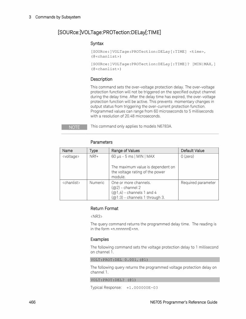
3 Commands by Subsystem
466 N6705 Programmer’s Reference Guide
[SOURce:]VOLTage:PROTection:DELay[:TIME]
Syntax
[SOURce:]VOLTage:PROTection:DELay[:TIME] <time>, (@<chanlist>)
[SOURce:]VOLTage:PROTection:DELay[:TIME]? [MIN|MAX,] (@<chanlist>)
Description
This command sets the over-voltage protection delay. The over-voltage protection function will not be triggered on the specified output channel during the delay time. After the delay time has expired, the over-voltage protection function will be active. This prevents momentary changes in output status from triggering the over-current protection function. Programmed values can range from 60 microseconds to 5 milliseconds with a resolution of 20.48 microseconds.
NOTE This command only applies to models N6783A.
Parameters
Name Type Range of Values Default Value <voltage> NRf+ 60 µs - 5 ms | MIN | MAX
The maximum value is dependent on the voltage rating of the power module.
0 (zero)
<chanlist> Numeric One or more channels. (@2) - channel 2 (@1,4) - channels 1 and 4 (@1:3) - channels 1 through 3.
Required parameter
Return Format
<NR3>
The query command returns the programmed delay time. The reading is in the form +n.nnnnnnE+nn.
Examples
The following command sets the voltage protection delay to 1 millisecond on channel 1.
VOLT:PROT:DEL 0.001,(@1)
The following query returns the programmed voltage protection delay on channel 1.
VOLT:PROT:DEL? (@1)
Typical Response: +1.000000E-03

Commands by Subsystem 3
N6705 Programmer’s Reference Guide 467
See Also
OUTPut:PROTection:CLEar
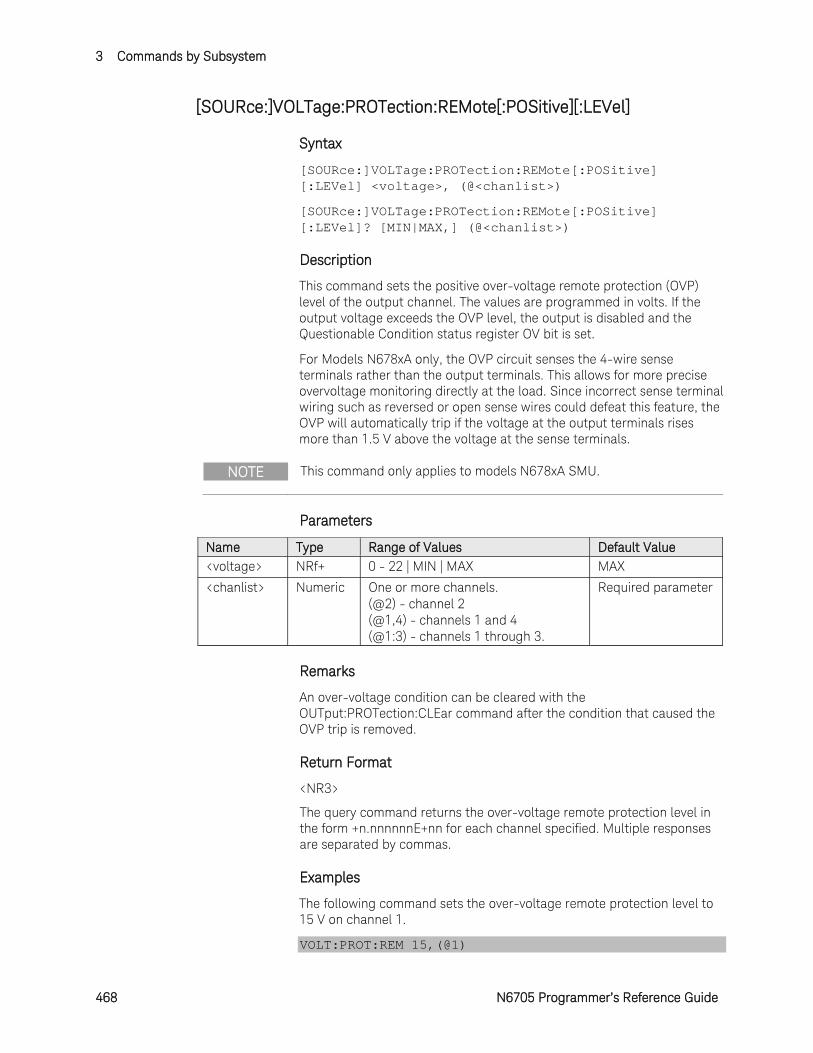
3 Commands by Subsystem
468 N6705 Programmer’s Reference Guide
[SOURce:]VOLTage:PROTection:REMote[:POSitive][:LEVel]
Syntax
[SOURce:]VOLTage:PROTection:REMote[:POSitive] [:LEVel] <voltage>, (@<chanlist>)
[SOURce:]VOLTage:PROTection:REMote[:POSitive] [:LEVel]? [MIN|MAX,] (@<chanlist>)
Description
This command sets the positive over-voltage remote protection (OVP) level of the output channel. The values are programmed in volts. If the output voltage exceeds the OVP level, the output is disabled and the Questionable Condition status register OV bit is set.
For Models N678xA only, the OVP circuit senses the 4-wire sense terminals rather than the output terminals. This allows for more precise overvoltage monitoring directly at the load. Since incorrect sense terminal wiring such as reversed or open sense wires could defeat this feature, the OVP will automatically trip if the voltage at the output terminals rises more than 1.5 V above the voltage at the sense terminals.
NOTE This command only applies to models N678xA SMU.
Parameters
Name Type Range of Values Default Value <voltage> NRf+ 0 - 22 | MIN | MAX MAX
<chanlist> Numeric One or more channels. (@2) - channel 2 (@1,4) - channels 1 and 4 (@1:3) - channels 1 through 3.
Required parameter
Remarks
An over-voltage condition can be cleared with the OUTput:PROTection:CLEar command after the condition that caused the OVP trip is removed.
Return Format
<NR3>
The query command returns the over-voltage remote protection level in the form +n.nnnnnnE+nn for each channel specified. Multiple responses are separated by commas.
Examples
The following command sets the over-voltage remote protection level to 15 V on channel 1.
VOLT:PROT:REM 15,(@1)
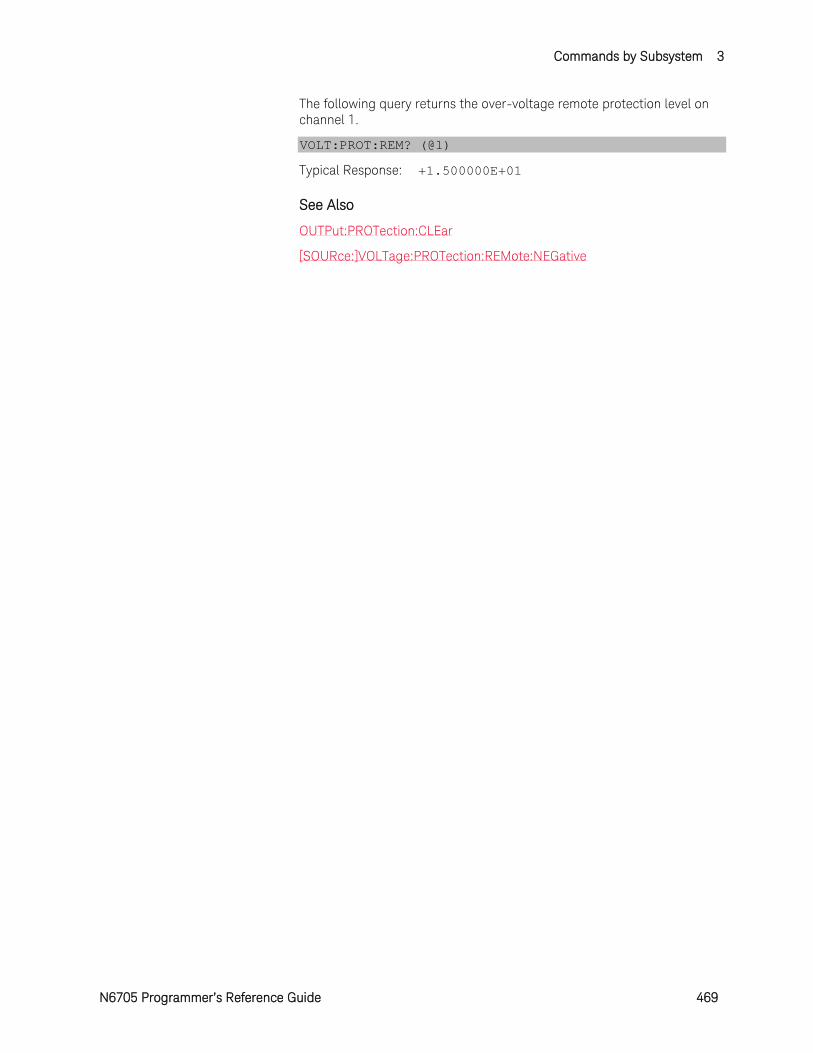
Commands by Subsystem 3
N6705 Programmer’s Reference Guide 469
The following query returns the over-voltage remote protection level on channel 1.
VOLT:PROT:REM? (@1)
Typical Response: +1.500000E+01
See Also
OUTPut:PROTection:CLEar
[SOURce:]VOLTage:PROTection:REMote:NEGative
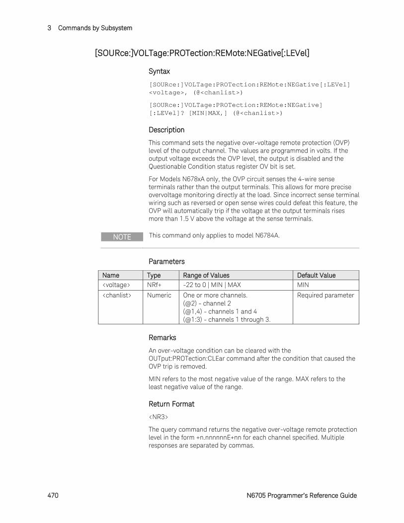
3 Commands by Subsystem
470 N6705 Programmer’s Reference Guide
[SOURce:]VOLTage:PROTection:REMote:NEGative[:LEVel]
Syntax
[SOURce:]VOLTage:PROTection:REMote:NEGative[:LEVel] <voltage>, (@<chanlist>)
[SOURce:]VOLTage:PROTection:REMote:NEGative] [:LEVel]? [MIN|MAX,] (@<chanlist>)
Description
This command sets the negative over-voltage remote protection (OVP) level of the output channel. The values are programmed in volts. If the output voltage exceeds the OVP level, the output is disabled and the Questionable Condition status register OV bit is set.
For Models N678xA only, the OVP circuit senses the 4-wire sense terminals rather than the output terminals. This allows for more precise overvoltage monitoring directly at the load. Since incorrect sense terminal wiring such as reversed or open sense wires could defeat this feature, the OVP will automatically trip if the voltage at the output terminals rises more than 1.5 V above the voltage at the sense terminals.
NOTE This command only applies to model N6784A.
Parameters
Name Type Range of Values Default Value <voltage> NRf+ -22 to 0 | MIN | MAX MIN
<chanlist> Numeric One or more channels. (@2) - channel 2 (@1,4) - channels 1 and 4 (@1:3) - channels 1 through 3.
Required parameter
Remarks
An over-voltage condition can be cleared with the OUTput:PROTection:CLEar command after the condition that caused the OVP trip is removed.
MIN refers to the most negative value of the range. MAX refers to the least negative value of the range.
Return Format
<NR3>
The query command returns the negative over-voltage remote protection level in the form +n.nnnnnnE+nn for each channel specified. Multiple responses are separated by commas.
Commands by Subsystem 3
N6705 Programmer’s Reference Guide 471
Examples
The following command sets the negative over-voltage remote protection level to -15 V on channel 1.
VOLT:PROT:REM:NEG -15,(@1)
The following query returns the negative over-voltage remote protection level on channel 1.
VOLT:PROT:REM:NEG? (@1)
Typical Response: -1.500000E+01
See Also
OUTPut:PROTection:CLEar
[SOURce;]VOLTage:PROTection:REMote
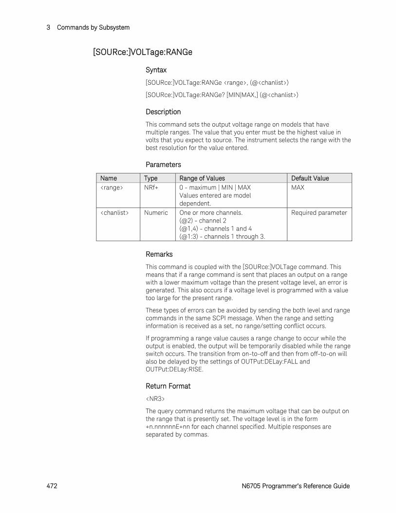
3 Commands by Subsystem
472 N6705 Programmer’s Reference Guide
[SOURce:]VOLTage:RANGe
Syntax
[SOURce:]VOLTage:RANGe <range>, (@<chanlist>)
[SOURce:]VOLTage:RANGe? [MIN|MAX,] (@<chanlist>)
Description
This command sets the output voltage range on models that have multiple ranges. The value that you enter must be the highest value in volts that you expect to source. The instrument selects the range with the best resolution for the value entered.
Parameters
Name Type Range of Values Default Value <range> NRf+ 0 - maximum | MIN | MAX
Values entered are model dependent.
MAX
<chanlist> Numeric One or more channels. (@2) - channel 2 (@1,4) - channels 1 and 4 (@1:3) - channels 1 through 3.
Required parameter
Remarks
This command is coupled with the [SOURce:]VOLTage command. This means that if a range command is sent that places an output on a range with a lower maximum voltage than the present voltage level, an error is generated. This also occurs if a voltage level is programmed with a value too large for the present range.
These types of errors can be avoided by sending the both level and range commands in the same SCPI message. When the range and setting information is received as a set, no range/setting conflict occurs.
If programming a range value causes a range change to occur while the output is enabled, the output will be temporarily disabled while the range switch occurs. The transition from on-to-off and then from off-to-on will also be delayed by the settings of OUTPut:DELay:FALL and OUTPut:DELay:RISE.
Return Format
<NR3>
The query command returns the maximum voltage that can be output on the range that is presently set. The voltage level is in the form +n.nnnnnnE+nn for each channel specified. Multiple responses are separated by commas.

Commands by Subsystem 3
N6705 Programmer’s Reference Guide 473
Examples
The following command sets the output voltage range to 5 V on channels 1 and 2.
VOLT:RANG 5,(@1,2)
The following query returns the programmed voltage range on channels 1 and 2.
VOLT:RANG? (@1,2)
Typical Response: +5.500000E+00,+5.500000E+00
See Also
[SOURce:]VOLTage[:LEVel][:IMMediate]
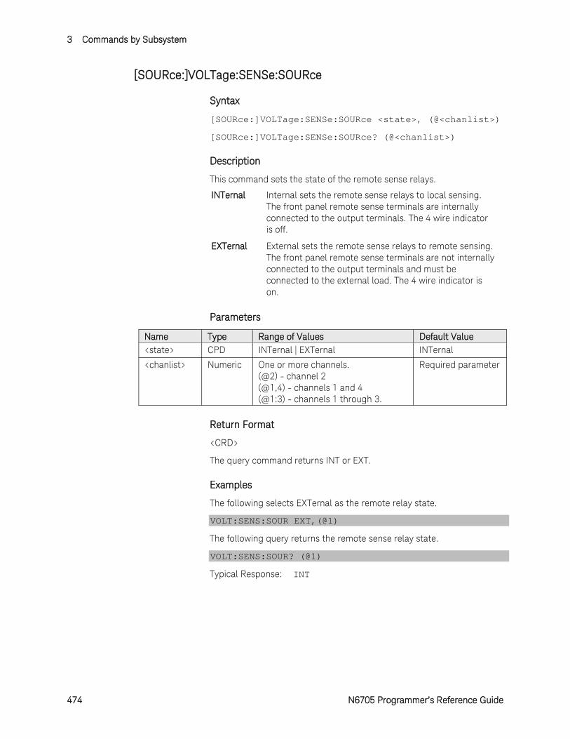
3 Commands by Subsystem
474 N6705 Programmer’s Reference Guide
[SOURce:]VOLTage:SENSe:SOURce
Syntax
[SOURce:]VOLTage:SENSe:SOURce <state>, (@<chanlist>)
[SOURce:]VOLTage:SENSe:SOURce? (@<chanlist>)
Description
This command sets the state of the remote sense relays.
INTernal Internal sets the remote sense relays to local sensing. The front panel remote sense terminals are internally connected to the output terminals. The 4 wire indicator is off.
EXTernal External sets the remote sense relays to remote sensing. The front panel remote sense terminals are not internally connected to the output terminals and must be connected to the external load. The 4 wire indicator is on.
Parameters
Name Type Range of Values Default Value <state> CPD INTernal | EXTernal INTernal
<chanlist> Numeric One or more channels. (@2) - channel 2 (@1,4) - channels 1 and 4 (@1:3) - channels 1 through 3.
Required parameter
Return Format
<CRD>
The query command returns INT or EXT.
Examples
The following selects EXTernal as the remote relay state.
VOLT:SENS:SOUR EXT,(@1)
The following query returns the remote sense relay state.
VOLT:SENS:SOUR? (@1)
Typical Response: INT
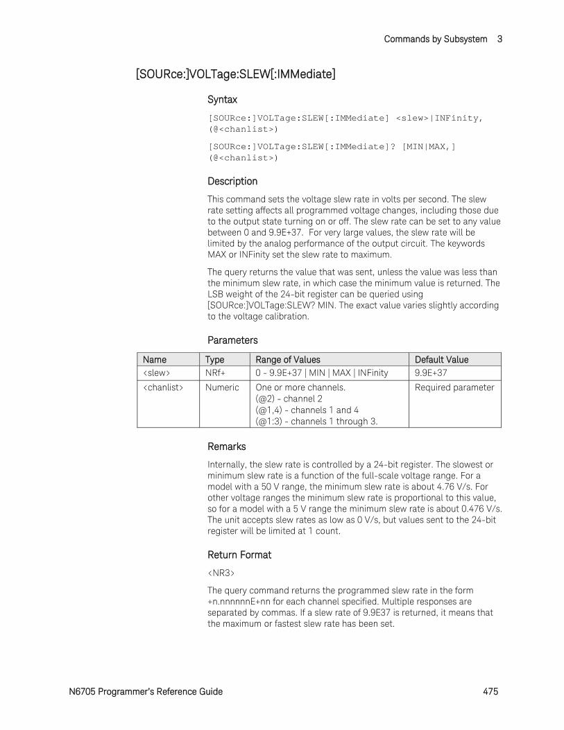
Commands by Subsystem 3
N6705 Programmer’s Reference Guide 475
[SOURce:]VOLTage:SLEW[:IMMediate]
Syntax
[SOURce:]VOLTage:SLEW[:IMMediate] <slew>|INFinity, (@<chanlist>)
[SOURce:]VOLTage:SLEW[:IMMediate]? [MIN|MAX,] (@<chanlist>)
Description
This command sets the voltage slew rate in volts per second. The slew rate setting affects all programmed voltage changes, including those due to the output state turning on or off. The slew rate can be set to any value between 0 and 9.9E+37. For very large values, the slew rate will be limited by the analog performance of the output circuit. The keywords MAX or INFinity set the slew rate to maximum.
The query returns the value that was sent, unless the value was less than the minimum slew rate, in which case the minimum value is returned. The LSB weight of the 24-bit register can be queried using [SOURce:]VOLTage:SLEW? MIN. The exact value varies slightly according to the voltage calibration.
Parameters
Name Type Range of Values Default Value <slew> NRf+ 0 - 9.9E+37 | MIN | MAX | INFinity 9.9E+37
<chanlist> Numeric One or more channels. (@2) - channel 2 (@1,4) - channels 1 and 4 (@1:3) - channels 1 through 3.
Required parameter
Remarks
Internally, the slew rate is controlled by a 24-bit register. The slowest or minimum slew rate is a function of the full-scale voltage range. For a model with a 50 V range, the minimum slew rate is about 4.76 V/s. For other voltage ranges the minimum slew rate is proportional to this value, so for a model with a 5 V range the minimum slew rate is about 0.476 V/s. The unit accepts slew rates as low as 0 V/s, but values sent to the 24-bit register will be limited at 1 count.
Return Format
<NR3>
The query command returns the programmed slew rate in the form +n.nnnnnnE+nn for each channel specified. Multiple responses are separated by commas. If a slew rate of 9.9E37 is returned, it means that the maximum or fastest slew rate has been set.
3 Commands by Subsystem
476 N6705 Programmer’s Reference Guide
Examples
The following command sets the slew rate to 5 volts per second on channel 1.
VOLT:SLEW 5,(@1)
The following query returns the programmed slew rate on channel 1.
VOLT:SLEW? (@1)
Typical Response: +5.000000E+00
See Also
[SOURce:]CURRent:SLEW
[SOURce:]VOLTage:SLEW:MAXimum
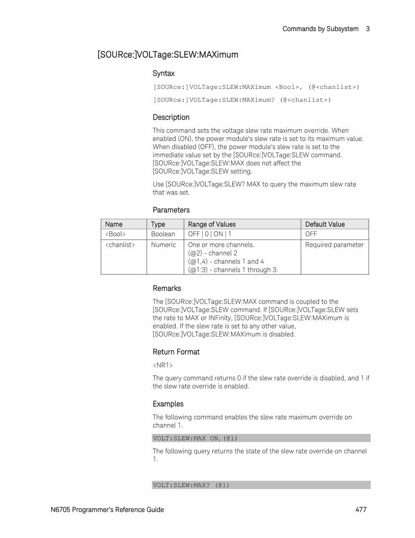
Commands by Subsystem 3
N6705 Programmer’s Reference Guide 477
[SOURce:]VOLTage:SLEW:MAXimum
Syntax
[SOURce:]VOLTage:SLEW:MAXimum <Bool>, (@<chanlist>)
[SOURce:]VOLTage:SLEW:MAXimum? (@<chanlist>)
Description
This command sets the voltage slew rate maximum override. When enabled (ON), the power module's slew rate is set to its maximum value. When disabled (OFF), the power module's slew rate is set to the immediate value set by the [SOURce:]VOLTage:SLEW command. [SOURce:]VOLTage:SLEW:MAX does not affect the [SOURce:]VOLTage:SLEW setting.
Use [SOURce:]VOLTage:SLEW? MAX to query the maximum slew rate that was set.
Parameters
Name Type Range of Values Default Value <Bool> Boolean OFF | 0 | ON | 1 OFF
<chanlist> Numeric One or more channels. (@2) - channel 2 (@1,4) - channels 1 and 4 (@1:3) - channels 1 through 3.
Required parameter
Remarks
The [SOURce:]VOLTage:SLEW:MAX command is coupled to the [SOURce:]VOLTage:SLEW command. If [SOURce:]VOLTage:SLEW sets the rate to MAX or INFinity, [SOURce:]VOLTage:SLEW:MAXimum is enabled. If the slew rate is set to any other value, [SOURce:]VOLTage:SLEW:MAXimum is disabled.
Return Format
<NR1>
The query command returns 0 if the slew rate override is disabled, and 1 if the slew rate override is enabled.
Examples
The following command enables the slew rate maximum override on channel 1.
VOLT:SLEW:MAX ON,(@1)
The following query returns the state of the slew rate override on channel 1.
VOLT:SLEW:MAX? (@1)
3 Commands by Subsystem
478 N6705 Programmer’s Reference Guide
Typical Response: 1
See Also
[SOURce:]VOLTage:SLEW
[SOURce:]CURRent:SLEW:MAXimum
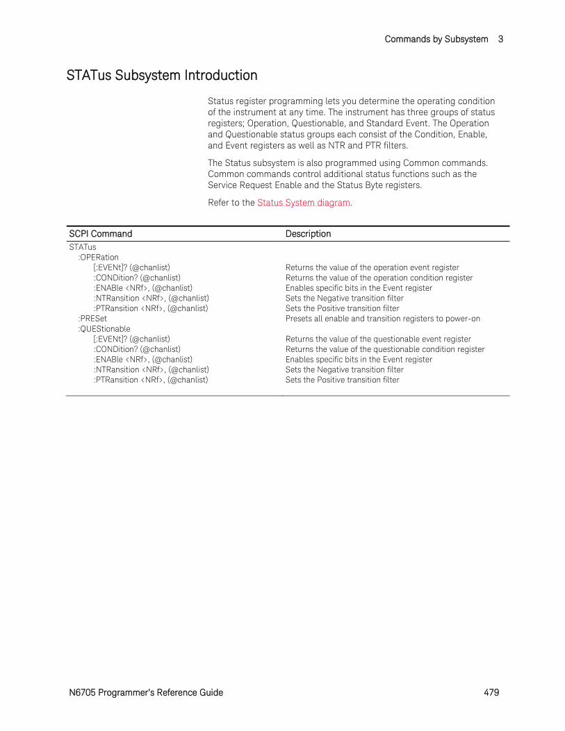
Commands by Subsystem 3
N6705 Programmer’s Reference Guide 479
STATus Subsystem Introduction
Status register programming lets you determine the operating condition of the instrument at any time. The instrument has three groups of status registers; Operation, Questionable, and Standard Event. The Operation and Questionable status groups each consist of the Condition, Enable, and Event registers as well as NTR and PTR filters.
The Status subsystem is also programmed using Common commands. Common commands control additional status functions such as the Service Request Enable and the Status Byte registers.
Refer to the Status System diagram.
SCPI Command Description STATus :OPERation [:EVENt]? (@chanlist) Returns the value of the operation event register :CONDition? (@chanlist) Returns the value of the operation condition register :ENABle <NRf>, (@chanlist) Enables specific bits in the Event register :NTRansition <NRf>, (@chanlist) Sets the Negative transition filter :PTRansition <NRf>, (@chanlist) Sets the Positive transition filter :PRESet Presets all enable and transition registers to power-on :QUEStionable [:EVENt]? (@chanlist) Returns the value of the questionable event register :CONDition? (@chanlist) Returns the value of the questionable condition register :ENABle <NRf>, (@chanlist) Enables specific bits in the Event register :NTRansition <NRf>, (@chanlist) Sets the Negative transition filter :PTRansition <NRf>, (@chanlist) Sets the Positive transition filter
3 Commands by Subsystem
480 N6705 Programmer’s Reference Guide
Operation Status Group
These registers record signals that occur during normal operation. The group consists of a Condition, PTR/NTR, Event, and Enable register. The outputs of the Operation Status register group are logically-ORed into the OPERation summary bit (7) of the Status Byte register.
Questionable Status Group
These registers record signals that indicate abnormal operation. The group consists of the same register types as the Operation Status group. The outputs of the Questionable Status group are logically-ORed into the QUEStionable summary bit (3) of the Status Byte register.
Standard Event Status Group
These registers are programmed by Common commands. The Standard Event event register latches events relating to communication status. It is a read-only register that is cleared when read. The Standard Event enable register functions similarly to the enable registers of the Operation and Questionable status groups.
Status Byte Register
This register summarizes the information from all other status groups as defined in the IEEE 488.2 Standard Digital Interface for Programmable Instrumentation.
MSS and RQS Bits
MSS is a real-time (unlatched) summary of all Status Byte register bits that are enabled by the Service Request Enable register. MSS is set whenever the instrument has one or more reasons for requesting service. *STB? reads the MSS in bit position 6 of the response but does not clear any of the bits in the Status Byte register.
The RQS bit is a latched version of the MSS bit. Whenever the instrument requests service, it sets the SRQ interrupt line true and latches RQS into bit 6 of the Status Byte register. When the controller does a serial poll, RQS is cleared inside the register and returned in bit position 6 of the response. The remaining bits of the Status Byte register are not disturbed.
MAV Bit and Output Queue
The Output Queue is a first-in, first-out (FIFO) data register that stores instrument-to-controller messages until the controller reads them. Whenever the queue holds one or more bytes, it sets the MAV bit (4) of the Status Byte register.
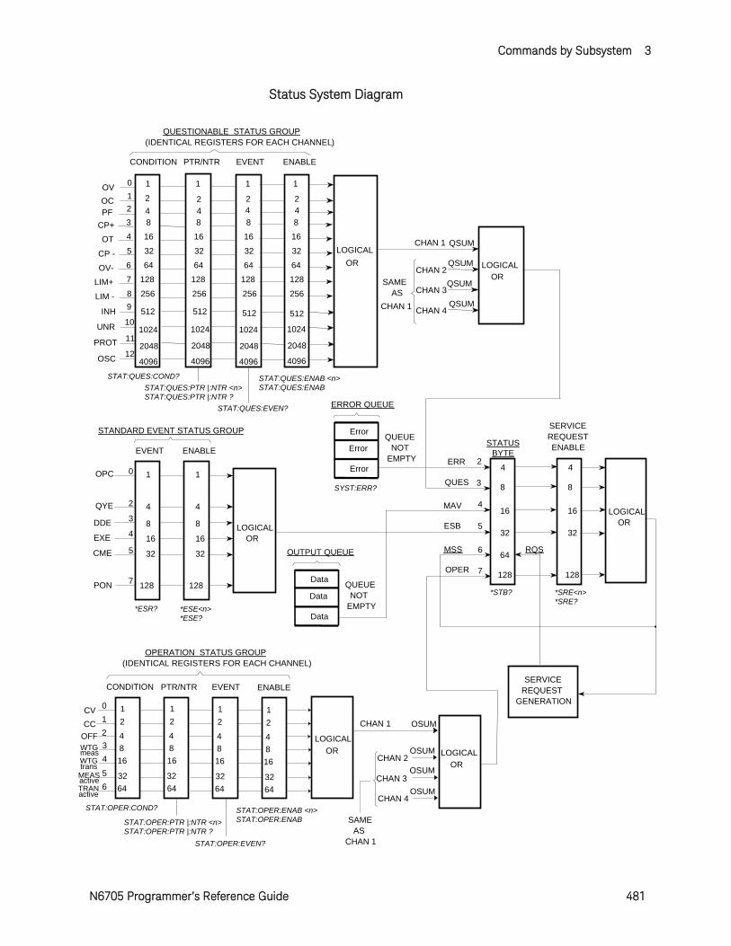
Commands by Subsystem 3
N6705 Programmer’s Reference Guide 481
Status System Diagram
LOGICALOR
LOGICALOR
PON
CME
EXE
DDE
QYE
OPC 0
2
3
4
5
7
1
4
8
16
32
128
1
4
8
16
32
128
EVENT ENABLE
STANDARD EVENT STATUS GROUP
ERROR QUEUE
QUEUENOT
EMPTY
Error
Error
Error
STATUS BYTE
SERVICEREQUESTENABLE
LOGICALOR
SERVICEREQUEST
GENERATION
8
16
32
128
8
16
32
128
RQS
OPER
MSS
ESB
MAV
QUES
4
5
6
7
UNR
OT
OV 0
4
QUESTIONABLE STATUS GROUP(IDENTICAL REGISTERS FOR EACH CHANNEL)
10
CONDITION
LOGICALOR
EVENT ENABLE
QSUMCHAN 1
SAMEAS
CHAN 1
LOGICALOR
PTR/NTR
1
16
1024
1
16
1024
1
16
1024
1
16
1024
3
LOGICALOR
CHAN 2
CHAN 3
CHAN 4
QSUM
QSUM
QSUM
CHAN 2
CHAN 3
CHAN 4
OSUM
CONDITION
0
2
PTR/NTR EVENT ENABLE
1CVCC
SAMEAS
CHAN 1
CHAN 1
OSUM
OSUM
12
4
OC 1
OFFOSUM
OPERATION STATUS GROUP(IDENTICAL REGISTERS FOR EACH CHANNEL)
PF 2 4 42
4 42 2 2
CP+ 3 8 888
CP - 5 32 323232
INH 9 512 512512512
64
43WTG 8
16
12
4816
12
4816
12
4816WTG
OUTPUT QUEUE
QUEUENOT
EMPTY
Data
Data
Data
2ERR
meas
trans
44
*STB? *SRE<n>*SRE?
*ESR?
STAT:QUES:COND?
*ESE<n>*ESE?
SYST:ERR?
STAT:QUES:PTR |:NTR <n>STAT:QUES:PTR |:NTR ?
STAT:QUES:EVEN?
STAT:QUES:ENAB <n> STAT:QUES:ENAB
STAT:OPER:COND?
STAT:OPER:EVEN?
STAT:OPER:ENAB <n> STAT:OPER:ENAB STAT:OPER:PTR |:NTR <n>
STAT:OPER:PTR |:NTR ?
PROT 112048 204820482048
OSC 124096 409640964096
LIM+ 7 128 128128128OV- 6 64 646464
LIM - 8 256 256256256
65MEAS 32
643264
3264
3264TRAN
active
active
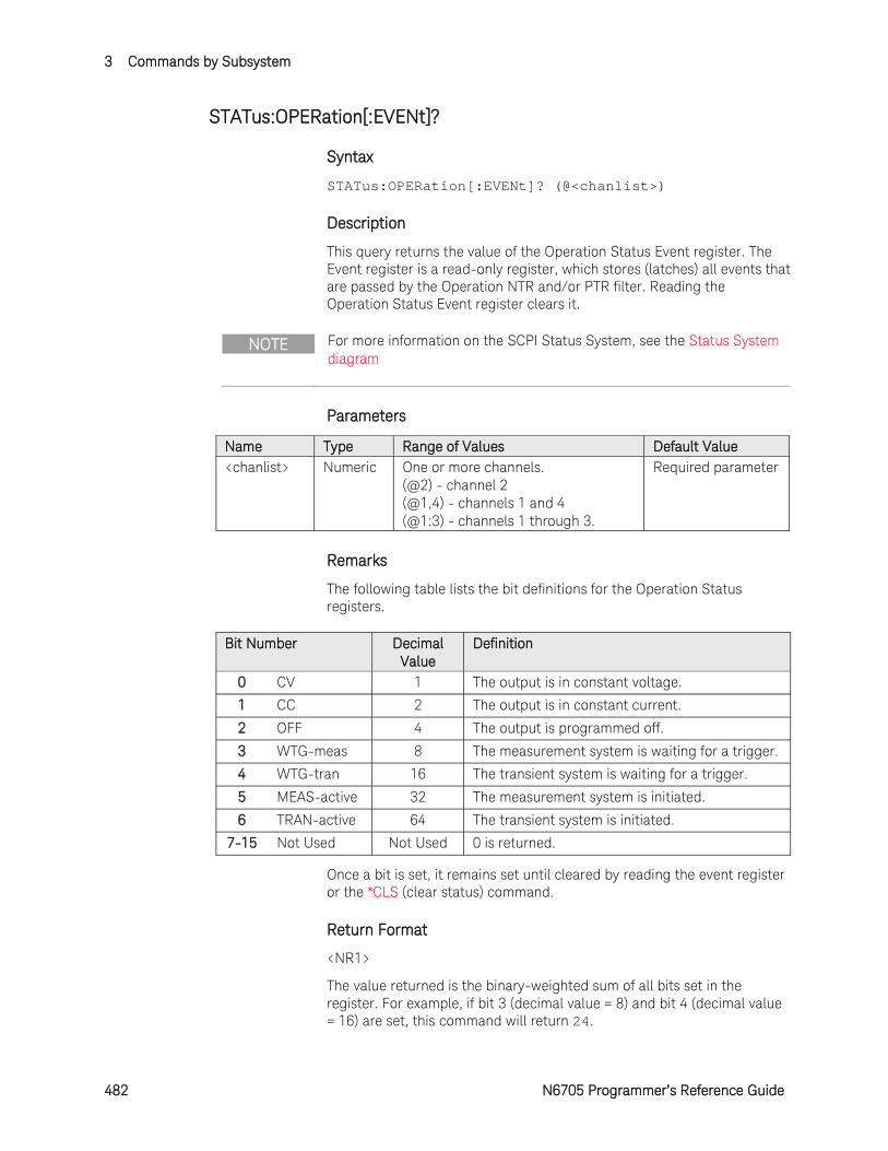
3 Commands by Subsystem
482 N6705 Programmer’s Reference Guide
STATus:OPERation[:EVENt]?
Syntax
STATus:OPERation[:EVENt]? (@<chanlist>)
Description
This query returns the value of the Operation Status Event register. The Event register is a read-only register, which stores (latches) all events that are passed by the Operation NTR and/or PTR filter. Reading the Operation Status Event register clears it.
NOTE For more information on the SCPI Status System, see the Status System diagram
Parameters
Name Type Range of Values Default Value <chanlist> Numeric One or more channels.
(@2) - channel 2 (@1,4) - channels 1 and 4 (@1:3) - channels 1 through 3.
Required parameter
Remarks
The following table lists the bit definitions for the Operation Status registers.
Bit Number Decimal Value
Definition
0 CV 1 The output is in constant voltage.
1 CC 2 The output is in constant current.
2 OFF 4 The output is programmed off.
3 WTG-meas 8 The measurement system is waiting for a trigger.
4 WTG-tran 16 The transient system is waiting for a trigger.
5 MEAS-active 32 The measurement system is initiated.
6 TRAN-active 64 The transient system is initiated.
7-15 Not Used Not Used 0 is returned.
Once a bit is set, it remains set until cleared by reading the event register or the *CLS (clear status) command.
Return Format
<NR1>
The value returned is the binary-weighted sum of all bits set in the register. For example, if bit 3 (decimal value = 8) and bit 4 (decimal value = 16) are set, this command will return 24.
Commands by Subsystem 3
N6705 Programmer’s Reference Guide 483
Example
The following command reads the Operation Status Event register.
STAT:OPER? (@1)
Typical Response: +24
See Also
STATus:OPERation:ENABle
*CLS
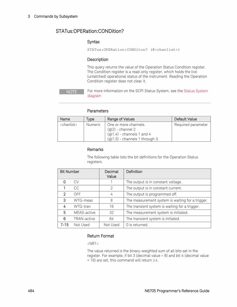
3 Commands by Subsystem
484 N6705 Programmer’s Reference Guide
STATus:OPERation:CONDition?
Syntax
STATus:OPERation:CONDiton? (@<chanlist>)
Description
This query returns the value of the Operation Status Condition register. The Condition register is a read-only register, which holds the live (unlatched) operational status of the instrument. Reading the Operation Condition register does not clear it.
NOTE For more information on the SCPI Status System, see the Status System diagram
Parameters
Name Type Range of Values Default Value <chanlist> Numeric One or more channels.
(@2) - channel 2 (@1,4) - channels 1 and 4 (@1:3) - channels 1 through 3.
Required parameter
Remarks
The following table lists the bit definitions for the Operation Status registers.
Bit Number Decimal Value
Definition
0 CV 1 The output is in constant voltage.
1 CC 2 The output is in constant current.
2 OFF 4 The output is programmed off.
3 WTG-meas 8 The measurement system is waiting for a trigger.
4 WTG-tran 16 The transient system is waiting for a trigger.
5 MEAS-active 32 The measurement system is initiated.
6 TRAN-active 64 The transient system is initiated.
7-15 Not Used Not Used 0 is returned.
Return Format
<NR1>
The value returned is the binary-weighted sum of all bits set in the register. For example, if bit 3 (decimal value = 8) and bit 4 (decimal value = 16) are set, this command will return 24.
Commands by Subsystem 3
N6705 Programmer’s Reference Guide 485
Example
The following command reads the Operation Status Condition register.
STAT:OPER:COND? (@1)
Typical Response: +24
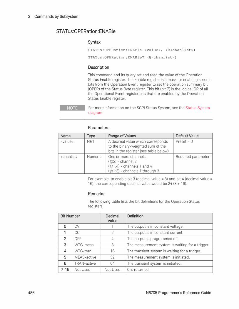
3 Commands by Subsystem
486 N6705 Programmer’s Reference Guide
STATus:OPERation:ENABle
Syntax
STATus:OPERation:ENABle <value>, (@<chanlist>)
STATus:OPERation:ENABle? (@<chanlist>)
Description
This command and its query set and read the value of the Operation Status Enable register. The Enable register is a mask for enabling specific bits from the Operation Event register to set the operation summary bit (OPER) of the Status Byte register. This bit (bit 7) is the logical OR of all the Operational Event register bits that are enabled by the Operation Status Enable register.
NOTE For more information on the SCPI Status System, see the Status System diagram
Parameters
Name Type Range of Values Default Value <value> NR1 A decimal value which corresponds
to the binary-weighted sum of the bits in the register (see table below).
Preset = 0
<chanlist> Numeric One or more channels. (@2) - channel 2 (@1,4) - channels 1 and 4 (@1:3) - channels 1 through 3.
Required parameter
For example, to enable bit 3 (decimal value = 8) and bit 4 (decimal value = 16), the corresponding decimal value would be 24 (8 + 16).
Remarks
The following table lists the bit definitions for the Operation Status registers.
Bit Number Decimal Value
Definition
0 CV 1 The output is in constant voltage.
1 CC 2 The output is in constant current.
2 OFF 4 The output is programmed off.
3 WTG-meas 8 The measurement system is waiting for a trigger.
4 WTG-tran 16 The transient system is waiting for a trigger.
5 MEAS-active 32 The measurement system is initiated.
6 TRAN-active 64 The transient system is initiated.
7-15 Not Used Not Used 0 is returned.
Commands by Subsystem 3
N6705 Programmer’s Reference Guide 487
The STATus:PRESet command will clear all bits in the enable register.
Return Format
<NR1>
The value returned is the binary-weighted sum of all bits set in the register. For example, if bit 3 (decimal value = 8) and bit 4 (decimal value = 16) are set, this command will return 24.
Examples
The following command enables bits 0 and 1 (decimal value = 3) in the enable register.
STAT:OPER:ENAB 3,(@1)
The following query returns which bits are enabled in the register.
STAT:OPER:ENAB? (@1)
Typical Response: +3
See Also
STATus:OPERation[:EVENt]?
STATus:PRESet

3 Commands by Subsystem
488 N6705 Programmer’s Reference Guide
STATus:OPERation:NTRansition
Syntax
STATus:OPERation:NTRansition <value>, (@<chanlist>)
STATus:OPERation:NTRansition? (@<chanlist>)
Description
These command sets and reads the value of the Operation NTR (Negative-Transition) register. This register serves as a polarity filter between the Operation Condition and Operation Event registers. When a bit in the Operation NTR register is set to 1, then a 1-to-0 transition of the corresponding bit in the Operation Condition register causes that bit in the Operation Event register to be set.
NOTE For more information on the SCPI Status System, see the Status System diagram
Parameters
Name Type Range of Values Default Value <value> NR1 A decimal value which corresponds
to the binary-weighted sum of the bits in the register (see table below).
Preset = 0
<chanlist> Numeric One or more channels. (@2) - channel 2 (@1,4) - channels 1 and 4 (@1:3) - channels 1 through 3.
Required parameter
For example, to enable bit 3 (decimal value = 8) and bit 4 (decimal value = 16), the corresponding decimal value would be 24 (8 + 16).
Remarks
The following table lists the bit definitions for the Operation Status registers.
Bit Number Decimal Value
Definition
0 CV 1 The output is in constant voltage.
1 CC 2 The output is in constant current.
2 OFF 4 The output is programmed off.
3 WTG-meas 8 The measurement system is waiting for a trigger.
4 WTG-tran 16 The transient system is waiting for a trigger.
5 MEAS-active 32 The measurement system is initiated.
6 TRAN-active 64 The transient system is initiated.
7-15 Not Used Not Used 0 is returned.

Commands by Subsystem 3
N6705 Programmer’s Reference Guide 489
If the same bits in both NTR and PTR registers are set to 1, then any transition of that bit at the Operation Condition register sets the corresponding bit in the Operation Event register.
If the same bits in both NTR and PTR registers are set to 0, then no transition of that bit at the Operation Condition register can set the corresponding bit in the Operation Event register.
The STATus:PRESet command will set all bits in the NTR register to 0.
Return Format
<NR1>
The value returned is the binary-weighted sum of all bits set in the register.
Examples
The following command enables bits 0 and 1 (decimal value = 3) in the NTR register.
STAT:OPER:NTR 3,(@1)
The following query returns which bits are enabled in the register.
STAT:OPER:NTR? (@1)
Typical Response: +3
See Also
STATus:OPERation:PTRansition
STATus:PRESet
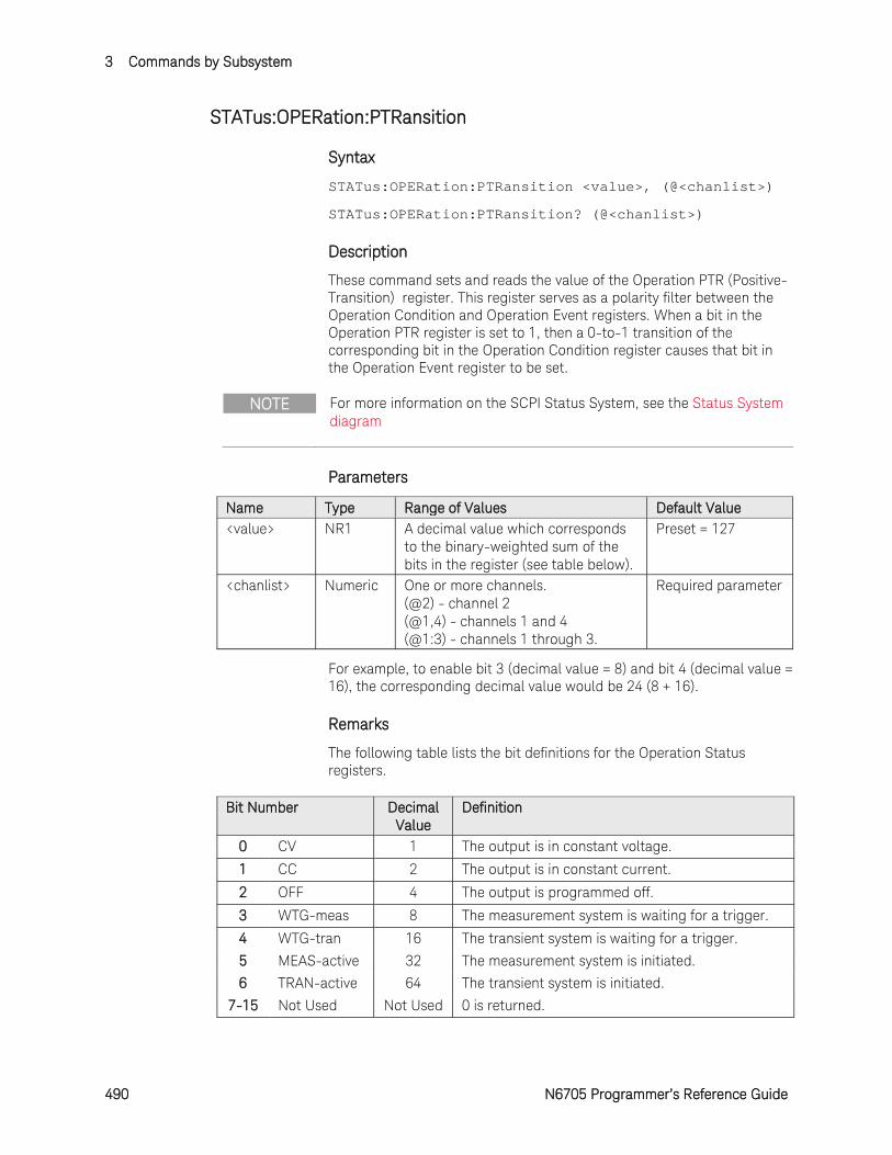
3 Commands by Subsystem
490 N6705 Programmer’s Reference Guide
STATus:OPERation:PTRansition
Syntax
STATus:OPERation:PTRansition <value>, (@<chanlist>)
STATus:OPERation:PTRansition? (@<chanlist>)
Description
These command sets and reads the value of the Operation PTR (Positive-Transition) register. This register serves as a polarity filter between the Operation Condition and Operation Event registers. When a bit in the Operation PTR register is set to 1, then a 0-to-1 transition of the corresponding bit in the Operation Condition register causes that bit in the Operation Event register to be set.
NOTE For more information on the SCPI Status System, see the Status System diagram
Parameters
Name Type Range of Values Default Value <value> NR1 A decimal value which corresponds
to the binary-weighted sum of the bits in the register (see table below).
Preset = 127
<chanlist> Numeric One or more channels. (@2) - channel 2 (@1,4) - channels 1 and 4 (@1:3) - channels 1 through 3.
Required parameter
For example, to enable bit 3 (decimal value = 8) and bit 4 (decimal value = 16), the corresponding decimal value would be 24 (8 + 16).
Remarks
The following table lists the bit definitions for the Operation Status registers.
Bit Number Decimal Value
Definition
0 CV 1 The output is in constant voltage.
1 CC 2 The output is in constant current.
2 OFF 4 The output is programmed off.
3 WTG-meas 8 The measurement system is waiting for a trigger.
4 WTG-tran 16 The transient system is waiting for a trigger.
5 MEAS-active 32 The measurement system is initiated.
6 TRAN-active 64 The transient system is initiated.
7-15 Not Used Not Used 0 is returned.
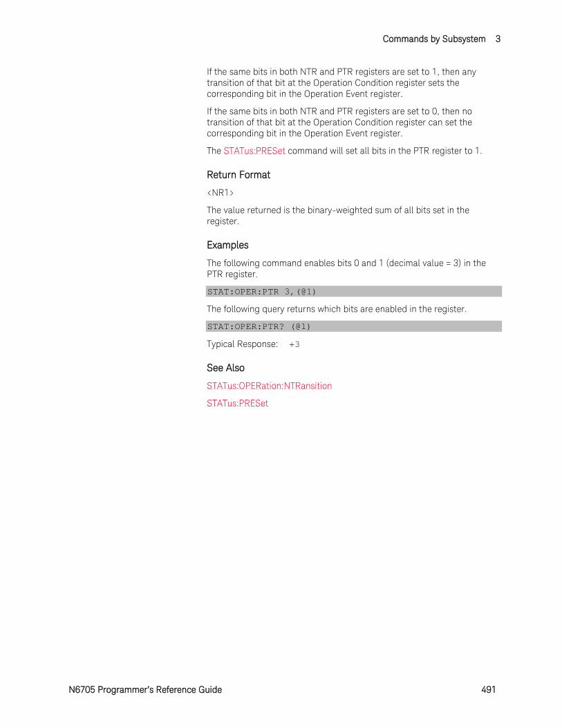
Commands by Subsystem 3
N6705 Programmer’s Reference Guide 491
If the same bits in both NTR and PTR registers are set to 1, then any transition of that bit at the Operation Condition register sets the corresponding bit in the Operation Event register.
If the same bits in both NTR and PTR registers are set to 0, then no transition of that bit at the Operation Condition register can set the corresponding bit in the Operation Event register.
The STATus:PRESet command will set all bits in the PTR register to 1.
Return Format
<NR1>
The value returned is the binary-weighted sum of all bits set in the register.
Examples
The following command enables bits 0 and 1 (decimal value = 3) in the PTR register.
STAT:OPER:PTR 3,(@1)
The following query returns which bits are enabled in the register.
STAT:OPER:PTR? (@1)
Typical Response: +3
See Also
STATus:OPERation:NTRansition
STATus:PRESet
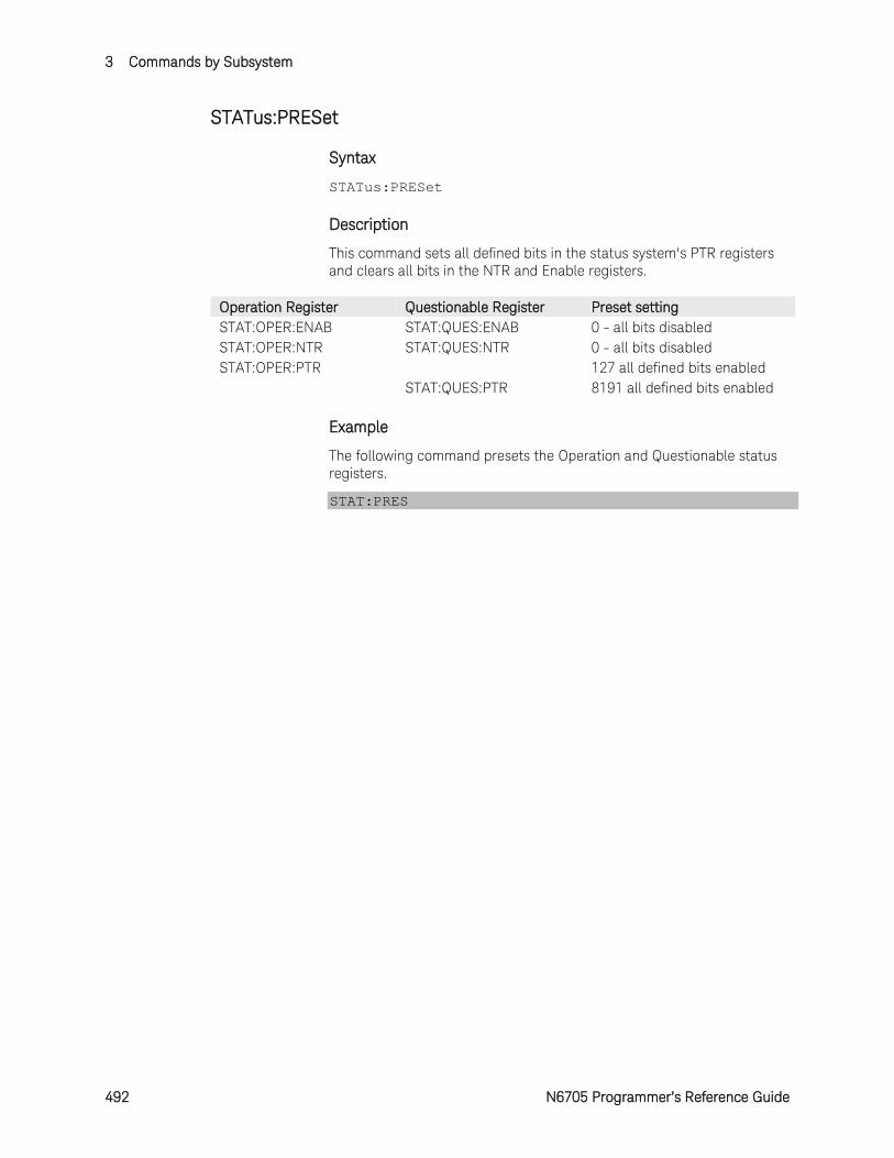
3 Commands by Subsystem
492 N6705 Programmer’s Reference Guide
STATus:PRESet
Syntax
STATus:PRESet
Description
This command sets all defined bits in the status system's PTR registers and clears all bits in the NTR and Enable registers.
Operation Register Questionable Register Preset setting STAT:OPER:ENAB STAT:QUES:ENAB 0 - all bits disabled STAT:OPER:NTR STAT:QUES:NTR 0 - all bits disabled STAT:OPER:PTR 127 all defined bits enabled
STAT:QUES:PTR 8191 all defined bits enabled
Example
The following command presets the Operation and Questionable status registers.
STAT:PRES
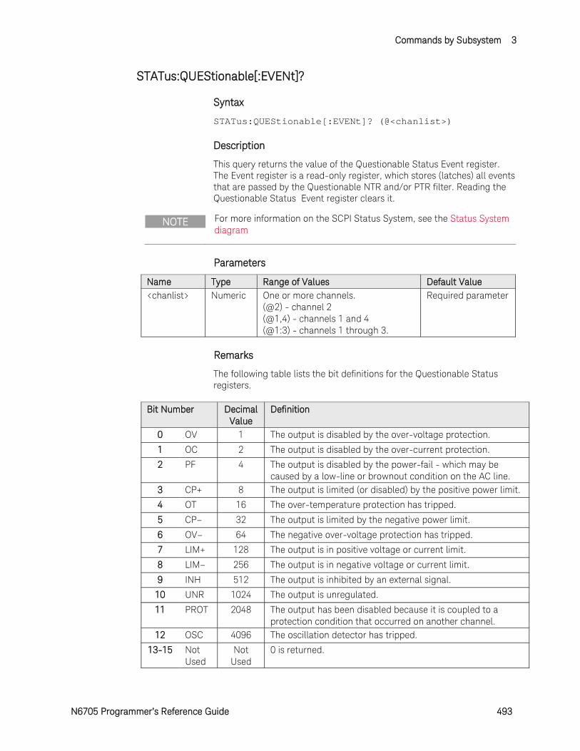
Commands by Subsystem 3
N6705 Programmer’s Reference Guide 493
STATus:QUEStionable[:EVENt]?
Syntax
STATus:QUEStionable[:EVENt]? (@<chanlist>)
Description
This query returns the value of the Questionable Status Event register. The Event register is a read-only register, which stores (latches) all events that are passed by the Questionable NTR and/or PTR filter. Reading the Questionable Status Event register clears it.
NOTE For more information on the SCPI Status System, see the Status System diagram
Parameters
Name Type Range of Values Default Value <chanlist> Numeric One or more channels.
(@2) - channel 2 (@1,4) - channels 1 and 4 (@1:3) - channels 1 through 3.
Required parameter
Remarks
The following table lists the bit definitions for the Questionable Status registers.
Bit Number Decimal Value
Definition
0 OV 1 The output is disabled by the over-voltage protection.
1 OC 2 The output is disabled by the over-current protection.
2 PF 4 The output is disabled by the power-fail - which may be caused by a low-line or brownout condition on the AC line.
3 CP+ 8 The output is limited (or disabled) by the positive power limit.
4 OT 16 The over-temperature protection has tripped.
5 CP– 32 The output is limited by the negative power limit.
6 OV– 64 The negative over-voltage protection has tripped.
7 LIM+ 128 The output is in positive voltage or current limit.
8 LIM– 256 The output is in negative voltage or current limit.
9 INH 512 The output is inhibited by an external signal.
10 UNR 1024 The output is unregulated.
11 PROT 2048 The output has been disabled because it is coupled to a protection condition that occurred on another channel.
12 OSC 4096 The oscillation detector has tripped.
13-15 Not Used
Not Used
0 is returned.
3 Commands by Subsystem
494 N6705 Programmer’s Reference Guide
Once a bit is set, it remains set until cleared by reading the event register or the *CLS (clear status) command.
Return Format
<NR1>
The value returned is the binary-weighted sum of all bits set in the register. For example, if bit 10 is set, this command will return 1024.
Example
The following command reads the Questionable Status Event register.
STAT:QUES?
Typical Response: +1024
See Also
STATus:QUEStionable:ENABle?
*CLS
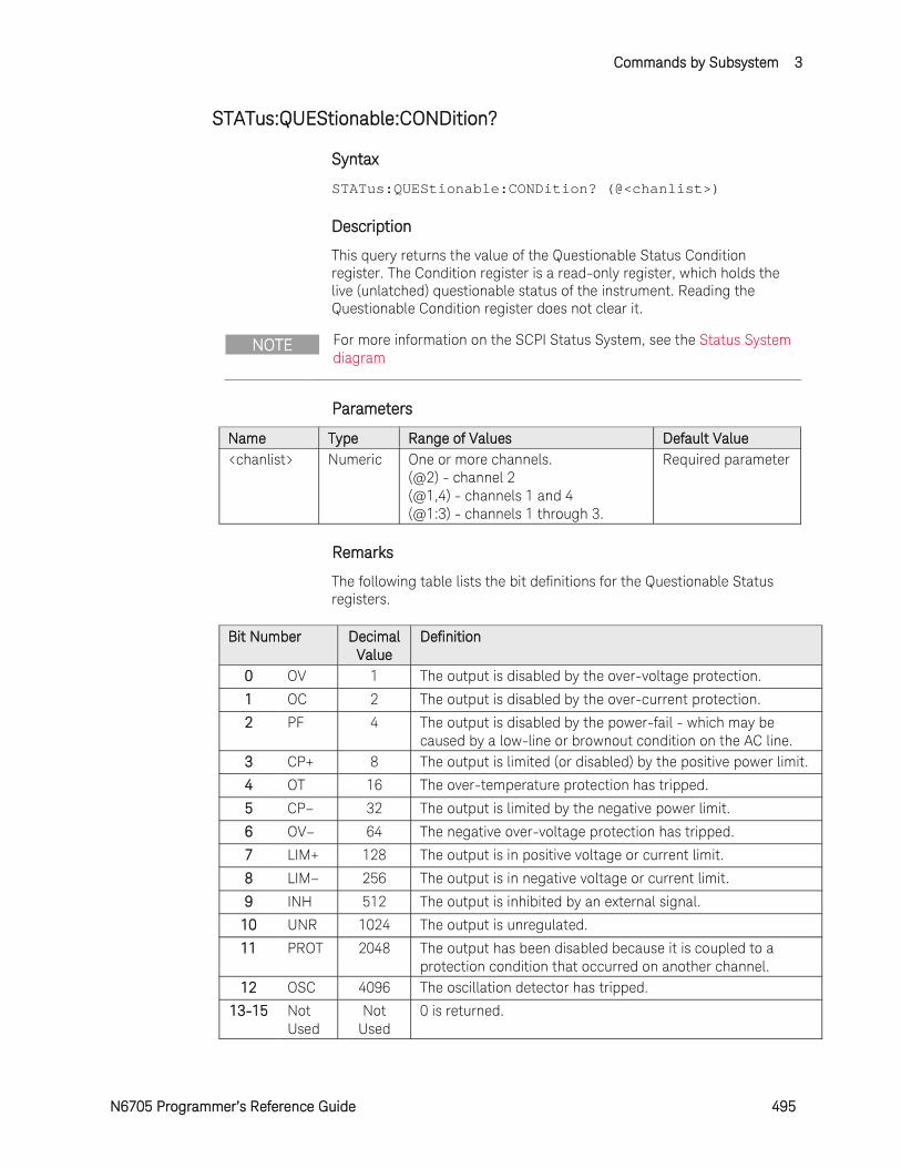
Commands by Subsystem 3
N6705 Programmer’s Reference Guide 495
STATus:QUEStionable:CONDition?
Syntax
STATus:QUEStionable:CONDition? (@<chanlist>)
Description
This query returns the value of the Questionable Status Condition register. The Condition register is a read-only register, which holds the live (unlatched) questionable status of the instrument. Reading the Questionable Condition register does not clear it.
NOTE For more information on the SCPI Status System, see the Status System diagram
Parameters
Name Type Range of Values Default Value <chanlist> Numeric One or more channels.
(@2) - channel 2 (@1,4) - channels 1 and 4 (@1:3) - channels 1 through 3.
Required parameter
Remarks
The following table lists the bit definitions for the Questionable Status registers.
Bit Number Decimal Value
Definition
0 OV 1 The output is disabled by the over-voltage protection.
1 OC 2 The output is disabled by the over-current protection.
2 PF 4 The output is disabled by the power-fail - which may be caused by a low-line or brownout condition on the AC line.
3 CP+ 8 The output is limited (or disabled) by the positive power limit.
4 OT 16 The over-temperature protection has tripped.
5 CP– 32 The output is limited by the negative power limit.
6 OV– 64 The negative over-voltage protection has tripped.
7 LIM+ 128 The output is in positive voltage or current limit.
8 LIM– 256 The output is in negative voltage or current limit.
9 INH 512 The output is inhibited by an external signal.
10 UNR 1024 The output is unregulated.
11 PROT 2048 The output has been disabled because it is coupled to a protection condition that occurred on another channel.
12 OSC 4096 The oscillation detector has tripped.
13-15 Not Used
Not Used
0 is returned.
3 Commands by Subsystem
496 N6705 Programmer’s Reference Guide
Return Format
<NR1>
The value returned is the binary-weighted sum of all bits set in the register. For example, if bit 10 is set, this command will return 1024.
Example
The following command reads the Questionable Status Condition register.
STAT:QUES:COND? (@1)
Typical Response: +1024
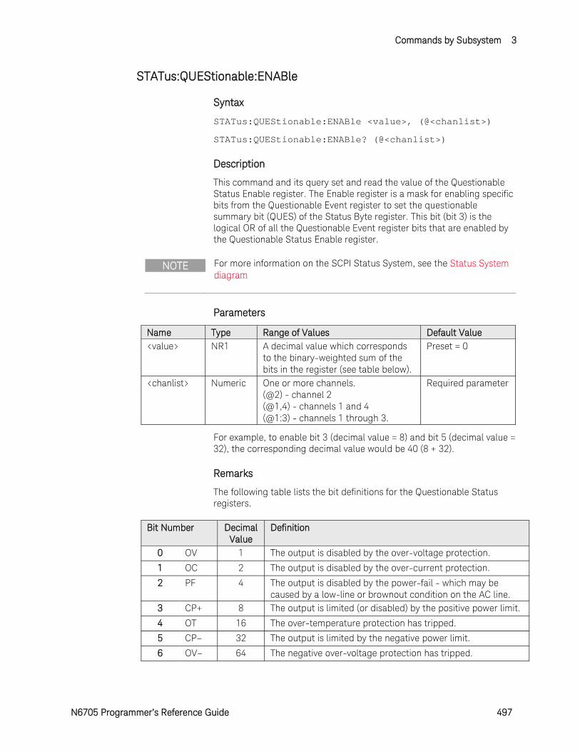
Commands by Subsystem 3
N6705 Programmer’s Reference Guide 497
STATus:QUEStionable:ENABle
Syntax
STATus:QUEStionable:ENABle <value>, (@<chanlist>)
STATus:QUEStionable:ENABle? (@<chanlist>)
Description
This command and its query set and read the value of the Questionable Status Enable register. The Enable register is a mask for enabling specific bits from the Questionable Event register to set the questionable summary bit (QUES) of the Status Byte register. This bit (bit 3) is the logical OR of all the Questionable Event register bits that are enabled by the Questionable Status Enable register.
NOTE For more information on the SCPI Status System, see the Status System diagram
Parameters
Name Type Range of Values Default Value <value> NR1 A decimal value which corresponds
to the binary-weighted sum of the bits in the register (see table below).
Preset = 0
<chanlist> Numeric One or more channels. (@2) - channel 2 (@1,4) - channels 1 and 4 (@1:3) - channels 1 through 3.
Required parameter
For example, to enable bit 3 (decimal value = 8) and bit 5 (decimal value = 32), the corresponding decimal value would be 40 (8 + 32).
Remarks
The following table lists the bit definitions for the Questionable Status registers.
Bit Number Decimal Value
Definition
0 OV 1 The output is disabled by the over-voltage protection.
1 OC 2 The output is disabled by the over-current protection.
2 PF 4 The output is disabled by the power-fail - which may be caused by a low-line or brownout condition on the AC line.
3 CP+ 8 The output is limited (or disabled) by the positive power limit.
4 OT 16 The over-temperature protection has tripped.
5 CP– 32 The output is limited by the negative power limit.
6 OV– 64 The negative over-voltage protection has tripped.
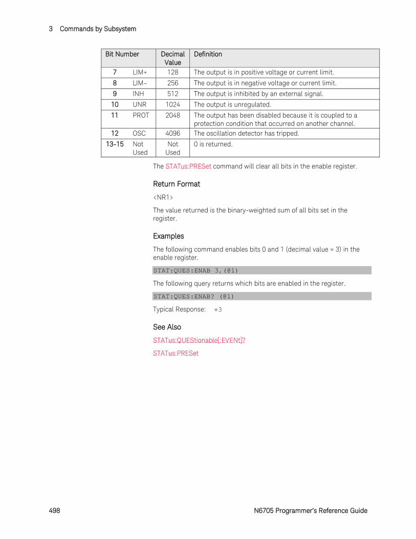
3 Commands by Subsystem
498 N6705 Programmer’s Reference Guide
Bit Number Decimal Value
Definition
7 LIM+ 128 The output is in positive voltage or current limit.
8 LIM– 256 The output is in negative voltage or current limit.
9 INH 512 The output is inhibited by an external signal.
10 UNR 1024 The output is unregulated.
11 PROT 2048 The output has been disabled because it is coupled to a protection condition that occurred on another channel.
12 OSC 4096 The oscillation detector has tripped.
13-15 Not Used
Not Used
0 is returned.
The STATus:PRESet command will clear all bits in the enable register.
Return Format
<NR1>
The value returned is the binary-weighted sum of all bits set in the register.
Examples
The following command enables bits 0 and 1 (decimal value = 3) in the enable register.
STAT:QUES:ENAB 3,(@1)
The following query returns which bits are enabled in the register.
STAT:QUES:ENAB? (@1)
Typical Response: +3
See Also
STATus:QUEStionable[:EVENt]?
STATus:PRESet
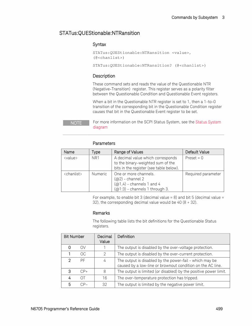
Commands by Subsystem 3
N6705 Programmer’s Reference Guide 499
STATus:QUEStionable:NTRansition
Syntax
STATus:QUEStionable:NTRansition <value>, (@<chanlist>)
STATus:QUEStionable:NTRansition? (@<chanlist>)
Description
These command sets and reads the value of the Questionable NTR (Negative-Transition) register. This register serves as a polarity filter between the Questionable Condition and Questionable Event registers.
When a bit in the Questionable NTR register is set to 1, then a 1-to-0 transition of the corresponding bit in the Questionable Condition register causes that bit in the Questionable Event register to be set.
NOTE For more information on the SCPI Status System, see the Status System diagram
Parameters
Name Type Range of Values Default Value <value> NR1 A decimal value which corresponds
to the binary-weighted sum of the bits in the register (see table below).
Preset = 0
<chanlist> Numeric One or more channels. (@2) - channel 2 (@1,4) - channels 1 and 4 (@1:3) - channels 1 through 3.
Required parameter
For example, to enable bit 3 (decimal value = 8) and bit 5 (decimal value = 32), the corresponding decimal value would be 40 (8 + 32).
Remarks
The following table lists the bit definitions for the Questionable Status registers.
Bit Number Decimal Value
Definition
0 OV 1 The output is disabled by the over-voltage protection.
1 OC 2 The output is disabled by the over-current protection.
2 PF 4 The output is disabled by the power-fail - which may be caused by a low-line or brownout condition on the AC line.
3 CP+ 8 The output is limited (or disabled) by the positive power limit.
4 OT 16 The over-temperature protection has tripped.
5 CP– 32 The output is limited by the negative power limit.
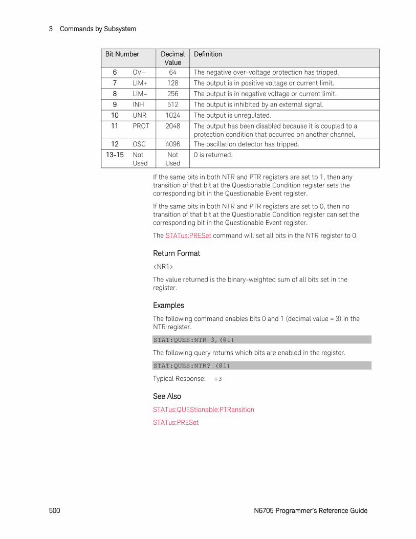
3 Commands by Subsystem
500 N6705 Programmer’s Reference Guide
Bit Number Decimal Value
Definition
6 OV– 64 The negative over-voltage protection has tripped.
7 LIM+ 128 The output is in positive voltage or current limit.
8 LIM– 256 The output is in negative voltage or current limit.
9 INH 512 The output is inhibited by an external signal.
10 UNR 1024 The output is unregulated.
11 PROT 2048 The output has been disabled because it is coupled to a protection condition that occurred on another channel.
12 OSC 4096 The oscillation detector has tripped.
13-15 Not Used
Not Used
0 is returned.
If the same bits in both NTR and PTR registers are set to 1, then any transition of that bit at the Questionable Condition register sets the corresponding bit in the Questionable Event register.
If the same bits in both NTR and PTR registers are set to 0, then no transition of that bit at the Questionable Condition register can set the corresponding bit in the Questionable Event register.
The STATus:PRESet command will set all bits in the NTR register to 0.
Return Format
<NR1>
The value returned is the binary-weighted sum of all bits set in the register.
Examples
The following command enables bits 0 and 1 (decimal value = 3) in the NTR register.
STAT:QUES:NTR 3,(@1)
The following query returns which bits are enabled in the register.
STAT:QUES:NTR? (@1)
Typical Response: +3
See Also
STATus:QUEStionable:PTRansition
STATus:PRESet

Commands by Subsystem 3
N6705 Programmer’s Reference Guide 501
STATus:QUEStionable:PTRansition
Syntax
STATus:QUEStionable:PTRansition <value>, (@<chanlist>)
STATus:QUEStionable:PTRansition? (@<chanlist>)
Description
These command sets and reads the value of the Questionable PTR (Positive-Transition) register. This register serves as a polarity filter between the Questionable Condition and Questionable Event registers.
When a bit in the Questionable PTR register is set to 1, then a 0-to-1 transition of the corresponding bit in the Questionable Condition register causes that bit in the Questionable Event register to be set.
NOTE For more information on the SCPI Status System, see the Status System diagram
Parameters
Name Type Range of Values Default Value <value> NR1 A decimal value which corresponds
to the binary-weighted sum of the bits in the register (see table below).
Preset = 8191
<chanlist> Numeric One or more channels. (@2) - channel 2 (@1,4) - channels 1 and 4 (@1:3) - channels 1 through 3.
Required parameter
For example, to enable bit 3 (decimal value = 8) and bit 5 (decimal value = 32), the corresponding decimal value would be 40 (8 + 32).
Remarks
The following table lists the bit definitions for the Questionable Status registers.
Bit Number Decimal Value
Definition
0 OV 1 The output is disabled by the over-voltage protection.
1 OC 2 The output is disabled by the over-current protection.
2 PF 4 The output is disabled by the power-fail - which may be caused by a low-line or brownout condition on the AC line.
3 CP+ 8 The output is limited (or disabled) by the positive power limit.
4 OT 16 The over-temperature protection has tripped.
5 CP– 32 The output is limited by the negative power limit.

3 Commands by Subsystem
502 N6705 Programmer’s Reference Guide
Bit Number Decimal Value
Definition
6 OV– 64 The negative over-voltage protection has tripped.
7 LIM+ 128 The output is in positive voltage or current limit.
8 LIM– 256 The output is in negative voltage or current limit.
9 INH 512 The output is inhibited by an external signal.
10 UNR 1024 The output is unregulated.
11 PROT 2048 The output has been disabled because it is coupled to a protection condition that occurred on another channel.
12 OSC 4096 The oscillation detector has tripped.
13-15 Not Used
Not Used
0 is returned.
If the same bits in both NTR and PTR registers are set to 1, then any transition of that bit at the Questionable Condition register sets the corresponding bit in the Questionable Event register.
If the same bits in both NTR and PTR registers are set to 0, then no transition of that bit at the Questionable Condition register can set the corresponding bit in the Questionable Event register.
The STATus:PRESet command will set all bits in the PTR register to 1.
Return Format
<NR1>
The value returned is the binary-weighted sum of all bits set in the register.
Examples
The following command enables bits 0 and 1 (decimal value = 3) in the PTR register.
STAT:QUES:PTR 3,(@1)
The following query returns which bits are enabled in the register.
STAT:QUES:PTR? (@1)
Typical Response: +3
See Also
STATus:QUEStionable:NTRansition
STATus:PRESet
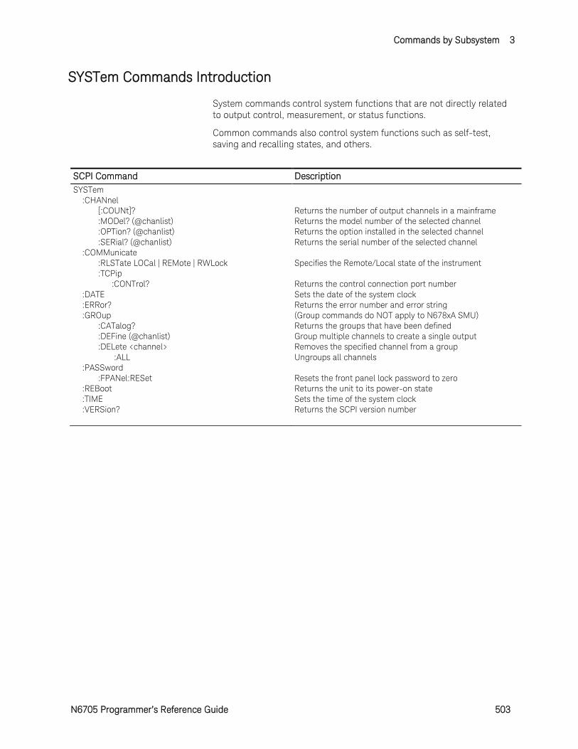
Commands by Subsystem 3
N6705 Programmer’s Reference Guide 503
SYSTem Commands Introduction
System commands control system functions that are not directly related to output control, measurement, or status functions.
Common commands also control system functions such as self-test, saving and recalling states, and others.
SCPI Command Description SYSTem :CHANnel [:COUNt]? Returns the number of output channels in a mainframe :MODel? (@chanlist) Returns the model number of the selected channel :OPTion? (@chanlist) Returns the option installed in the selected channel :SERial? (@chanlist) Returns the serial number of the selected channel :COMMunicate :RLSTate LOCal | REMote | RWLock Specifies the Remote/Local state of the instrument :TCPip :CONTrol? Returns the control connection port number :DATE Sets the date of the system clock :ERRor? Returns the error number and error string :GROup (Group commands do NOT apply to N678xA SMU) :CATalog? Returns the groups that have been defined :DEFine (@chanlist) Group multiple channels to create a single output :DELete <channel> Removes the specified channel from a group :ALL Ungroups all channels :PASSword :FPANel:RESet Resets the front panel lock password to zero :REBoot Returns the unit to its power-on state :TIME Sets the time of the system clock :VERSion? Returns the SCPI version number
3 Commands by Subsystem
504 N6705 Programmer’s Reference Guide
SYSTem:CHANnel[:COUNt]?
Syntax
SYSTem:CHANnel[:COUNt]?
Description
This query returns the number of output channels in a mainframe.
Return Format
<NR1>
The number of output channels.
Example
The following query returns the number of channels.
SYST:CHAN?
Typical Response: +4
Commands by Subsystem 3
N6705 Programmer’s Reference Guide 505
SYSTem:CHANnel:MODel?
Syntax
SYSTem:CHANnel:MODel? (@<chanlist>)
Description
This query returns the model number of the specified output channels.
Parameters
Name Type Range of Values Default Value <chanlist> Numeric One or more channels.
(@2) - channel 2 (@1,4) - channels 1 and 4 (@1:3) - channels 1 through 3.
Required parameter
Return Format
<AARD>
The model number of the output channel. Multiple responses are separated by commas.
Example
The following query returns the model number in channels 2 and 3.
SYST:CHAN:MOD? (@2,3)
Typical Response: N6751A,N6761A
3 Commands by Subsystem
506 N6705 Programmer’s Reference Guide
SYSTem:CHANnel:OPTion?
Syntax
SYSTem:CHANnel:OPTion? (@<chanlist>)
Description
This query returns a list of options installed in each channel specified in the channel list.
Parameters
Name Type Range of Values Default Value <chanlist> Numeric One or more channels.
(@2) - channel 2 (@1,4) - channels 1 and 4 (@1:3) - channels 1 through 3.
Required parameter
Return Format
<SRD>
The query command returns an ASCII string enclosed in double quotes. If no option is installed, an empty quoted string ("") is returned. Multiple responses are separated by commas.
Example
The following query returns the options in channels 1 through 3.
SYST:CHAN:OPT? (@1:3)
Response with options installed in channels 1 and 2, none in channel 3:
"Opt 760","Opt 760",""

Commands by Subsystem 3
N6705 Programmer’s Reference Guide 507
SYSTem:CHANnel:SERial?
Syntax
SYSTem:CHANnel:SERial? (@<chanlist>)
Description
This query returns the serial number of the specified output channels.
Parameters
Name Type Range of Values Default Value <chanlist> Numeric One or more channels.
(@2) - channel 2 (@1,4) - channels 1 and 4 (@1:3) - channels 1 through 3.
Required parameter
Return Format
<AARD>
The serial number of the output channel. Multiple responses are separated by semicolons.
Example
The following query returns the serial numbers in channels 2 and 3.
SYST:CHAN:SER? (@2,3)
Typical Response: MY00123456;MY00234567
3 Commands by Subsystem
508 N6705 Programmer’s Reference Guide
SYSTem:COMMunicate:RLSTate
Syntax
SYSTem:COMMunicate:RLSTate <state>
SYSTem:COMMunicate:RLSTate?
Description
This command configures the remote/local state of the instrument according to the following settings:
LOCal The instrument is set to front panel and remote interface control.
REMote The instrument is set to front panel and remote interface control.
RWLock The front panel keys are disabled. The instrument can only be controlled via the remote interface. This programmable setting is completely independent from the front panel lock/unlock function that is available from the front panel menu.
NOTE The remote/local state is unaffected by *RST or any SCPI commands other than SYSTem:COMMunicate:RLState.
Parameters
Name Type Range of Values Default Value <state> CPD LOCal | REMote | RWLock LOCal
(set at power-on)
Remarks
The remote/local instrument state can also be set by other interface commands over the GPIB and some other I/O interfaces.
When multiple remote programming interfaces are active, the interface with the most recently changed remote/local state determines the instrument’s remote/local state.
Return Format
<CRD>
The query command returns LOC, REM, or RWL.
Examples
The following command sets the remote/local state of the instrument.
SYST:COMM:RLST REMote
The following query returns the remote/local state of the instrument.
Commands by Subsystem 3
N6705 Programmer’s Reference Guide 509
SYST:COMM:RLST?
Typical Response: LOC
3 Commands by Subsystem
510 N6705 Programmer’s Reference Guide
SYSTem:COMMunicate:TCPip:CONTrol?
Syntax
SYSTem:COMMunicate:TCPip:CONTrol?
Description
This query returns the control connection port number. This is used to open a control socket connection to the instrument. Unlike the data socket, which uses a fixed port number (5025 for Keysight instruments), the port number for a control socket varies, and must be obtained using this query.
NOTE Refer to chapter 3 of the User's Guide under “Using Sockets” for more information.
Remarks
After the control port number is obtained, a control socket connection can be opened.
The control socket connection can only be used by a client to send a Device Clear to the instrument or to detect Service Request (SRQ) events.
All commands to the control socket must be terminated with a newline <NL>, and all query responses returned on the control socket will be terminated with a newline.
Return Format
<NR1>
The Control connection port number.
Example
The following query returns the Control connection port number.
SYST:COMM:TCP:CONT?
Typical Response: +5000
Commands by Subsystem 3
N6705 Programmer’s Reference Guide 511
SYSTem:DATE
Syntax
SYSTem:DATE <yyyy>,<mm>,<dd>
SYSTem:DATE?
Description
This command sets the date of the real time clock in year (yyyy), month (mm), and day (dd).
Parameters
Name Type Range of Values Default Value
<yyyy> NR1 An 4-digit integer representing the year
Required parameter
<mm> NR1 An integer from 1 to 12 Required parameter
<dd> NR1 An integer from 1 to 31 Required parameter
Return Format
<NR1>
The query command returns comma-separated values that correspond to the year, month, and day.
Examples
The following command sets the date (April 1, 2007).
SYST:DATE 2007,4,1
The following query returns the date.
SYST:DATE?
Typical Response: 2007,4,1
3 Commands by Subsystem
512 N6705 Programmer’s Reference Guide
SYSTem:ERRor?
Syntax
SYSTem:ERRor?
Description
This query returns the next error number and its corresponding message string from the error queue.
For a complete listing of instrument and system error messages, see SCPI Error Messages.
Remarks
The front-panel ERR annunciator turns on when one or more errors are currently stored in the error queue.
Errors are retrieved in first-in-first-out (FIFO) order. The first error returned is the first error that was stored.
Errors are cleared as you read them. When you have read all errors from the error queue, the ERR annunciator turns off and the errors are cleared.
If more errors have accumulated than the queue can hold, the last error stored in the queue (the most recent error) is replaced with -350,"Error queue overflow". No additional errors are stored until you remove errors from the queue. If no errors have occurred when you read the error queue, the instrument responds with +0,"No error".
The error queue is cleared by the *CLS (Clear Status) command and when power is cycled. The errors are also cleared when you read the error queue.
Return Format
<NR1>,<SRD>
The error string may contain up to 80 characters and consists of an error number and an error string enclosed in double quotes. For example: -113,"Undefined header".
Example
The following query reads and clears one error.
SYST:ERR?
Typical Response: -101,"Invalid character"
Commands by Subsystem 3
N6705 Programmer’s Reference Guide 513
SYSTem:GROup:CATalog?
Syntax
SYSTem:GROup:CATalog?
Description
This query returns information about channels that are grouped. The defined groups are enclosed in quotes.
NOTE This command does NOT apply to models N678xA SMU.
Return Format
<SRD>
The defined groups in quotes. Multiple responses are separated by commas.
Example
The following query returns the channels that are grouped.
SYST:GRO:CAT?
Response with 4 channels; none grouped: "1","2","3","4"
Response with channels 1 + 2 grouped; 3 + 4 grouped: "1,2","3,4"
Response with channels 1 - 3 grouped; channel 4 not grouped: "1,2,3","4"
3 Commands by Subsystem
514 N6705 Programmer’s Reference Guide
SYSTem:GROup:DEFine
Syntax
SYSTem:GROup:DEFine (@<chanlist>)
Description
This command defines a list of output channels as a paralleled group. This effectively creates a single output with higher current and power capability. You can group up to four channels per mainframe. All channels in a group must have identical model numbers and have identical options installed.
All grouped channels must have their output terminals and, if remote sensing, their sense terminals connected in parallel.
After the channels are wired in parallel and defined as a group, they can be addressed using any of the channel-specific SCPI commands by sending the channel number of the LOWEST channel in the group.
NOTE This command does NOT apply to models N678xA SMU.
Parameters
Name Type Range of Values Default Value <chanlist> Numeric Two or more channels.
(@1,2) - channels 1 and 2 (@1:3) - channels 1 through 3.
Required parameter
Remarks
For the group changes to take effect, you must reboot the unit. Either cycle AC power or send the SYSTem:REBoot command.
Group channel definitions are stored in non-volatile memory and are unaffected by *RST or *RCL.
Group channel settings (voltage, current, etc.) are set and saved by *RST or *RCL.
This command also deletes any previously saved states.
Example
The following command defines channels 1 , 2, and 3 as a group.
SYST:GRO:DEF (@1:3)
The following command defines channels 1 and 4 as a group.
SYST:GRO:DEF (@1,4)
Commands by Subsystem 3
N6705 Programmer’s Reference Guide 515
SYSTem:GROup:DELete
Syntax
SYSTem:GROup:DELete <channel>
Description
This command removes the indicated channel from a group. It leaves the other channels in the group intact.
When ungrouping a channel, you must also remove the parallel connections between the output and sense terminals of that channel.
NOTE This command does NOT apply to models N678xA SMU.
Parameters
Name Type Range of Values Default Value <channel> NR1 1 | 2 | 3 | 4 Required parameter
Remarks
For the group changes to take effect, you must reboot the unit. Either cycle AC power or send the SYSTem:REBoot command.
This command also deletes any previously saved states.
Example
The following command deletes channel 3 from a group.
SYST:GRO:DEL 3
3 Commands by Subsystem
516 N6705 Programmer’s Reference Guide
SYSTem:GROup:DELete:ALL
Syntax
SYSTem:GROup:DELete:ALL
Description
This command deletes all groups on a mainframe. It returns any channels that have been grouped back to an ungrouped state.
When ungrouping channels, you must also remove all paralleled sense and output terminal connections between channels.
NOTE This command does NOT apply to models N678xA SMU.
Remarks
For the group changes to take effect, you must reboot the unit. Either cycle AC power or send the SYSTem:REBoot command.
This command also deletes any previously saved states.
Example
The following command deletes all groups.
SYST:GRO:DEL:ALL
Commands by Subsystem 3
N6705 Programmer’s Reference Guide 517
SYSTem:PASSword:FPANel:RESet
Syntax
SYSTem:PASSword:FPANel:RESet
Description
This command resets the front panel lockout password to the factory-shipped setting, which is zero (0). This command does not reset the calibration password.
NOTE The front panel password can also be reset to 0 by setting an internal switch on the unit. Refer to the Service Manual under “Calibration Switches” for more information. This switch does NOT reset the front panel lockout password.
Example
The following command resets the front panel password.
SYST:PASS:FPAN:RES
See Also
*RST
3 Commands by Subsystem
518 N6705 Programmer’s Reference Guide
SYSTem:REBoot
Syntax
SYSTem:REBoot
Description
This command causes the instrument to reboot to its power-on state.
Example
The following command reboots the instrument.
SYST:REB
See Also
*RST

Commands by Subsystem 3
N6705 Programmer’s Reference Guide 519
SYSTem:TIME
Syntax
SYSTem:TIME <hh>,<mm>,<ss>
SYSTem:TIME?
Description
This command sets the real time clock in hours (hh), minutes (mm), and seconds (ss).
Parameters
Name Type Range of Values Default Value
<hh> NR1 An integer from 0 to 23 Required parameter
<mm> NR1 An integer from 0 to 59 Required parameter
<ss> NR1 An integer from 0 to 59 Required parameter
Return Format
<NR1>
The query command returns comma-separated values that correspond to the hours, minutes, and seconds.
Examples
The following command sets a time.
SYST:TIME 12,30,0
The following query returns the time of the clock.
SYST:TIME?
Typical Response: 12,30,0
3 Commands by Subsystem
520 N6705 Programmer’s Reference Guide
SYSTem:VERSion?
Syntax
SYSTem:VERSion?
Description
This command returns the version of the SCPI (Standard Commands for Programmable Instruments) standard with which the instrument is in compliance.
Return Format
<SRD>
The command returns a string in the form "YYYY.V", where YYYY represents the year of the version and V represents a version for that year.
Example
The following query returns the SCPI version.
SYST:VERS?
Typical Response: "2007.0"
Commands by Subsystem 3
N6705 Programmer’s Reference Guide 521
TRIGger Subsystem Introduction
Trigger commands control the remote triggering of the instrument. They specify the trigger source for the transient and the measurement system and also generate software triggers.
The Common command *TRG is also used to trigger the instrument.
SCPI Command Description TRIGger :ACQuire [:IMMediate] (@chanlist) Triggers the measurement immediately :CURRent [:LEVel] <NRf>, (@chanlist) Sets the current trigger level :SLOPe POSitive | NEGative, (@chanlist)
Sets the current trigger slope
:SOURce <source>, (@chanlist) Sets the measurement trigger source <source> = BUS, CURRent<n>,EXTernal, PIN<n>, TRANsient<n>, VOLTage<n> :TOUTput [:ENABle] <Bool>, (@chanlist) Enables measurement triggers to be sent to a digital port pin :VOLTage [:LEVel] <NRf>, (@chanlist) Sets the voltage trigger level :SLOPe POSitive | NEGative, (@chanlist)
Sets the voltage trigger slope
:ARB:SOURce BUS | IMMediate | EXTernal Sets the arbitrary waveform trigger source :DLOG [:IMMediate] Triggers the internal data logger immediately :CURRent [:LEVel] <NRf>, (@chanlist) Sets the current trigger level of the data logger :SLOPe POSitive | NEGative, (@chanlist) Sets the current trigger slope of the data logger :SOURce <source> Sets the internal data logger trigger source <source> = BUS, CURRent<n>, EXTernal, IMMediate, VOLTage<n>, ARSK, OOOK :VOLTage [:LEVel] <NRf>, (@chanlist) Sets the voltage trigger level of the data logger :SLOPe POSitive | NEGative, (@chanlist) Sets the voltage trigger slope of the data logger :ELOG [:IMMediate] (@chanlist) Triggers the external data logger immediately :SOURce <source>, (@chanlist) Sets the external data logger trigger source <source> = BUS, EXTernal, IMMediate, PIN<n> :HISTogram [:IMMediate] (@chanlist) Triggers the current histogram immediately (N6781A, N6782A,
N6785A, N6786A) :SOURce <source>, (@chanlist) Sets the current histogram trigger source (N6781A, N6782A, N6785A,
N6786A) <source> = BUS, EXTernal, IMMediate, PIN<n> :TRANsient [:IMMediate] (@chanlist) Triggers the output immediately :SOURce <source>, (@chanlist) Sets the output trigger source <source> = BUS, EXTernal, IMMediate, PIN<n>, TRANsient<n>
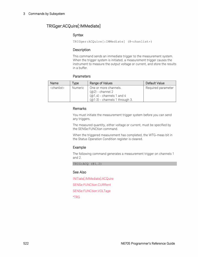
3 Commands by Subsystem
522 N6705 Programmer’s Reference Guide
TRIGger:ACQuire[:IMMediate]
Syntax
TRIGger:ACQuire[:IMMediate] (@<chanlist>)
Description
This command sends an immediate trigger to the measurement system. When the trigger system is initiated, a measurement trigger causes the instrument to measure the output voltage or current, and store the results in a buffer.
Parameters
Name Type Range of Values Default Value <chanlist> Numeric One or more channels.
(@2) - channel 2 (@1,4) - channels 1 and 4 (@1:3) - channels 1 through 3.
Required parameter
Remarks
You must initiate the measurement trigger system before you can send any triggers.
The measured quantity, either voltage or current, must be specified by the SENSe:FUNCtion command.
When the triggered measurement has completed, the WTG-meas bit in the Status Operation Condition register is cleared.
Example
The following command generates a measurement trigger on channels 1 and 2.
TRIG:ACQ (@1,2)
See Also
INITiate[:IMMediate]:ACQuire
SENSe:FUNCtion:CURRent
SENSe:FUNCtion:VOLTage
*TRG
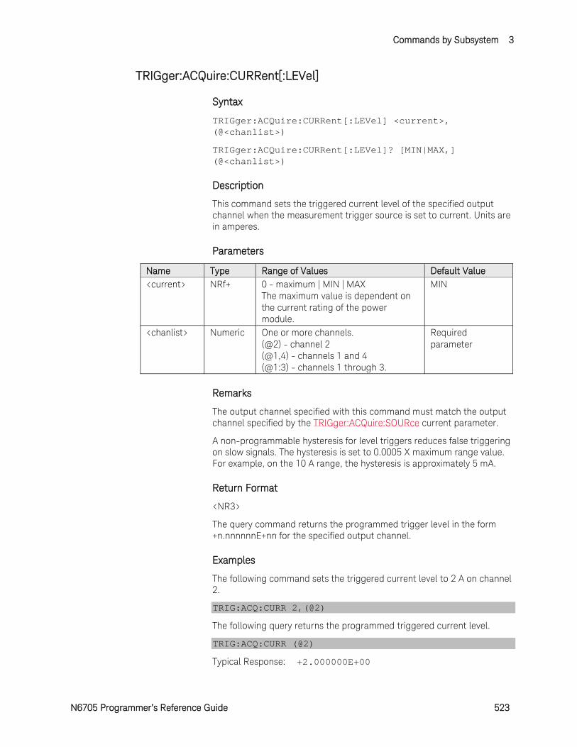
Commands by Subsystem 3
N6705 Programmer’s Reference Guide 523
TRIGger:ACQuire:CURRent[:LEVel]
Syntax
TRIGger:ACQuire:CURRent[:LEVel] <current>, (@<chanlist>)
TRIGger:ACQuire:CURRent[:LEVel]? [MIN|MAX,] (@<chanlist>)
Description
This command sets the triggered current level of the specified output channel when the measurement trigger source is set to current. Units are in amperes.
Parameters
Name Type Range of Values Default Value <current> NRf+ 0 - maximum | MIN | MAX
The maximum value is dependent on the current rating of the power module.
MIN
<chanlist> Numeric One or more channels. (@2) - channel 2 (@1,4) - channels 1 and 4 (@1:3) - channels 1 through 3.
Required parameter
Remarks
The output channel specified with this command must match the output channel specified by the TRIGger:ACQuire:SOURce current parameter.
A non-programmable hysteresis for level triggers reduces false triggering on slow signals. The hysteresis is set to 0.0005 X maximum range value. For example, on the 10 A range, the hysteresis is approximately 5 mA.
Return Format
<NR3>
The query command returns the programmed trigger level in the form +n.nnnnnnE+nn for the specified output channel.
Examples
The following command sets the triggered current level to 2 A on channel 2.
TRIG:ACQ:CURR 2,(@2)
The following query returns the programmed triggered current level.
TRIG:ACQ:CURR (@2)
Typical Response: +2.000000E+00

3 Commands by Subsystem
524 N6705 Programmer’s Reference Guide
See Also
TRIGger:ACQuire:SOURce
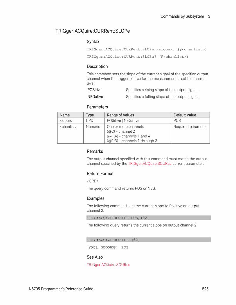
Commands by Subsystem 3
N6705 Programmer’s Reference Guide 525
TRIGger:ACQuire:CURRent:SLOPe
Syntax
TRIGger:ACQuire:CURRent:SLOPe <slope>, (@<chanlist>)
TRIGger:ACQuire:CURRent:SLOPe? (@<chanlist>)
Description
This command sets the slope of the current signal of the specified output channel when the trigger source for the measurement is set to a current level.
POSitive Specifies a rising slope of the output signal.
NEGative Specifies a falling slope of the output signal.
Parameters
Name Type Range of Values Default Value <slope> CPD POSitive | NEGative POS
<chanlist> Numeric One or more channels. (@2) - channel 2 (@1,4) - channels 1 and 4 (@1:3) - channels 1 through 3.
Required parameter
Remarks
The output channel specified with this command must match the output channel specified by the TRIGger:ACQuire:SOURce current parameter.
Return Format
<CRD>
The query command returns POS or NEG.
Examples
The following command sets the current slope to Positive on output channel 2.
TRIG:ACQ:CURR:SLOP POS,(@2)
The following query returns the current slope on output channel 2.
TRIG:ACQ:CURR:SLOP (@2)
Typical Response: POS
See Also
TRIGger:ACQuire:SOURce
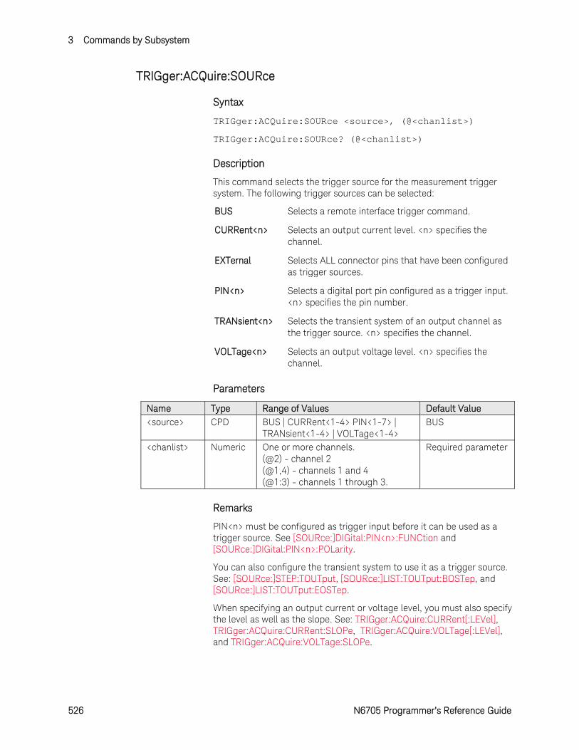
3 Commands by Subsystem
526 N6705 Programmer’s Reference Guide
TRIGger:ACQuire:SOURce
Syntax
TRIGger:ACQuire:SOURce <source>, (@<chanlist>)
TRIGger:ACQuire:SOURce? (@<chanlist>)
Description
This command selects the trigger source for the measurement trigger system. The following trigger sources can be selected:
BUS Selects a remote interface trigger command.
CURRent<n> Selects an output current level. <n> specifies the channel.
EXTernal Selects ALL connector pins that have been configured as trigger sources.
PIN<n> Selects a digital port pin configured as a trigger input. <n> specifies the pin number.
TRANsient<n> Selects the transient system of an output channel as the trigger source. <n> specifies the channel.
VOLTage<n> Selects an output voltage level. <n> specifies the channel.
Parameters
Name Type Range of Values Default Value <source> CPD BUS | CURRent<1-4> PIN<1-7> |
TRANsient<1-4> | VOLTage<1-4> BUS
<chanlist> Numeric One or more channels. (@2) - channel 2 (@1,4) - channels 1 and 4 (@1:3) - channels 1 through 3.
Required parameter
Remarks
PIN<n> must be configured as trigger input before it can be used as a trigger source. See [SOURce:]DIGital:PIN<n>:FUNCtion and [SOURce:]DIGital:PIN<n>:POLarity.
You can also configure the transient system to use it as a trigger source. See: [SOURce:]STEP:TOUTput, [SOURce:]LIST:TOUTput:BOSTep, and [SOURce:]LIST:TOUTput:EOSTep.
When specifying an output current or voltage level, you must also specify the level as well as the slope. See: TRIGger:ACQuire:CURRent[:LEVel], TRIGger:ACQuire:CURRent:SLOPe, TRIGger:ACQuire:VOLTage[:LEVel], and TRIGger:ACQuire:VOLTage:SLOPe.
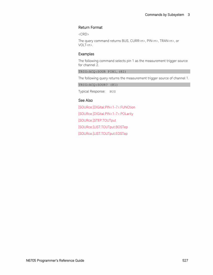
Commands by Subsystem 3
N6705 Programmer’s Reference Guide 527
Return Format
<CRD>
The query command returns BUS, CURR<n>, PIN<n>, TRAN<n>, or VOLT<n>.
Examples
The following command selects pin 1 as the measurement trigger source for channel 2.
TRIG:ACQ:SOUR PIN1,(@2)
The following query returns the measurement trigger source of channel 1.
TRIG:ACQ:SOUR? (@1)
Typical Response: BUS
See Also
[SOURce:]DIGital:PIN<1-7>:FUNCtion
[SOURce:]DIGital:PIN<1-7>:POLarity
[SOURce:]STEP:TOUTput
[SOURce:]LIST:TOUTput:BOSTep
[SOURce:]LIST:TOUTput:EOSTep
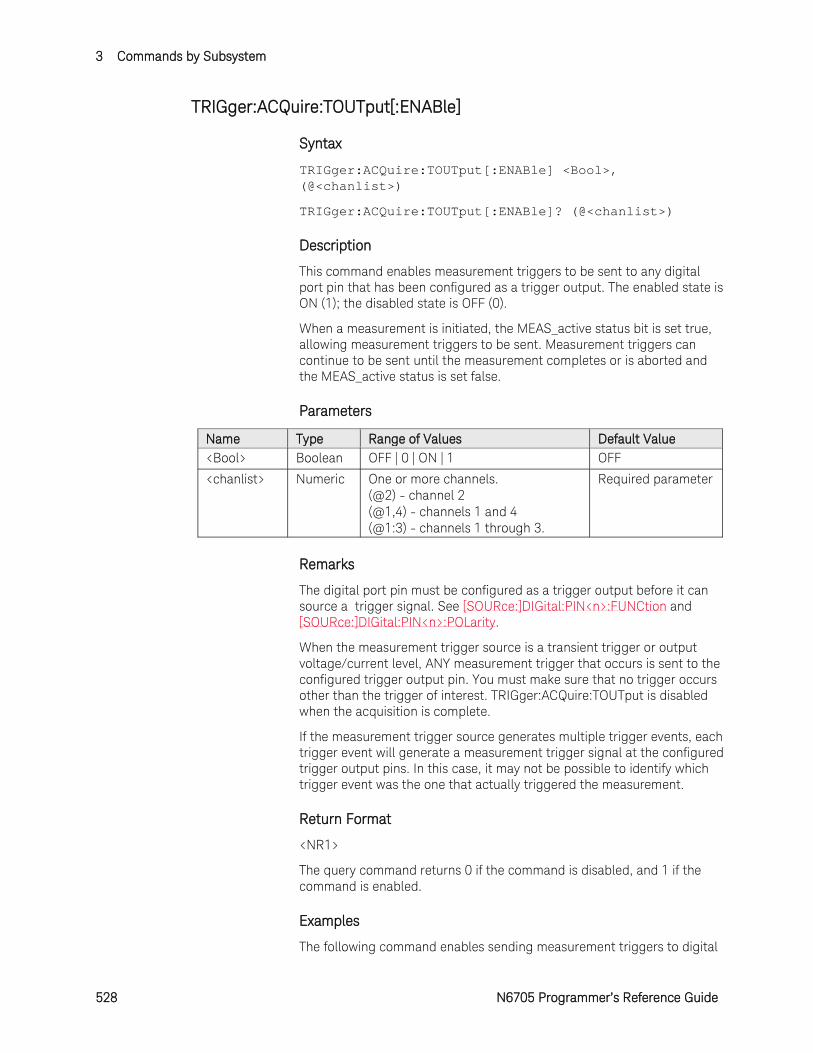
3 Commands by Subsystem
528 N6705 Programmer’s Reference Guide
TRIGger:ACQuire:TOUTput[:ENABle]
Syntax
TRIGger:ACQuire:TOUTput[:ENABle] <Bool>, (@<chanlist>)
TRIGger:ACQuire:TOUTput[:ENABle]? (@<chanlist>)
Description
This command enables measurement triggers to be sent to any digital port pin that has been configured as a trigger output. The enabled state is ON (1); the disabled state is OFF (0).
When a measurement is initiated, the MEAS_active status bit is set true, allowing measurement triggers to be sent. Measurement triggers can continue to be sent until the measurement completes or is aborted and the MEAS_active status is set false.
Parameters
Name Type Range of Values Default Value <Bool> Boolean OFF | 0 | ON | 1 OFF
<chanlist> Numeric One or more channels. (@2) - channel 2 (@1,4) - channels 1 and 4 (@1:3) - channels 1 through 3.
Required parameter
Remarks
The digital port pin must be configured as a trigger output before it can source a trigger signal. See [SOURce:]DIGital:PIN<n>:FUNCtion and [SOURce:]DIGital:PIN<n>:POLarity.
When the measurement trigger source is a transient trigger or output voltage/current level, ANY measurement trigger that occurs is sent to the configured trigger output pin. You must make sure that no trigger occurs other than the trigger of interest. TRIGger:ACQuire:TOUTput is disabled when the acquisition is complete.
If the measurement trigger source generates multiple trigger events, each trigger event will generate a measurement trigger signal at the configured trigger output pins. In this case, it may not be possible to identify which trigger event was the one that actually triggered the measurement.
Return Format
<NR1>
The query command returns 0 if the command is disabled, and 1 if the command is enabled.
Examples
The following command enables sending measurement triggers to digital
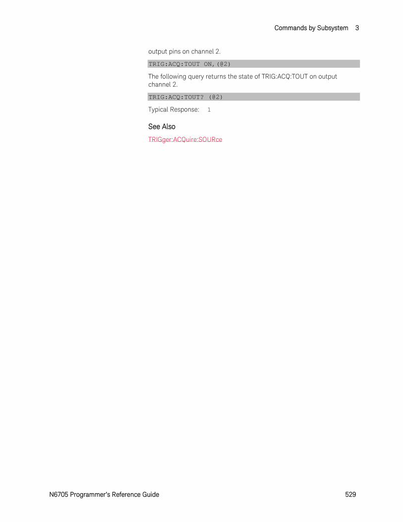
Commands by Subsystem 3
N6705 Programmer’s Reference Guide 529
output pins on channel 2.
TRIG:ACQ:TOUT ON,(@2)
The following query returns the state of TRIG:ACQ:TOUT on output channel 2.
TRIG:ACQ:TOUT? (@2)
Typical Response: 1
See Also
TRIGger:ACQuire:SOURce
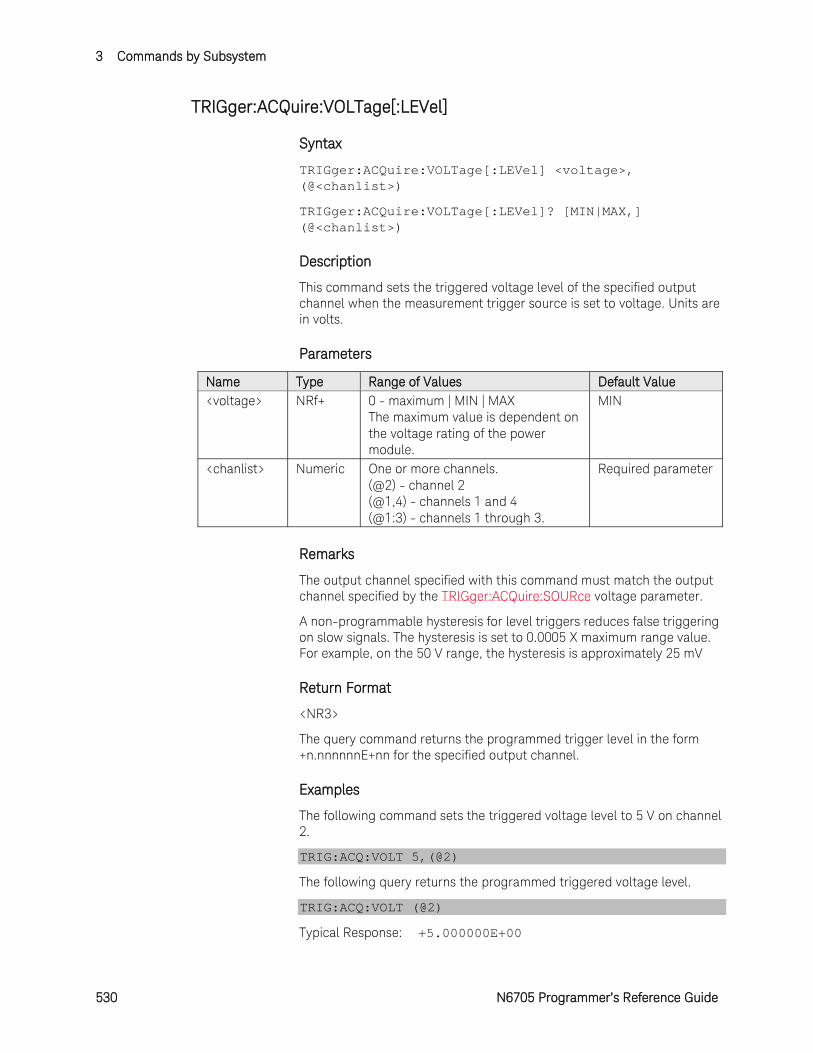
3 Commands by Subsystem
530 N6705 Programmer’s Reference Guide
TRIGger:ACQuire:VOLTage[:LEVel]
Syntax
TRIGger:ACQuire:VOLTage[:LEVel] <voltage>, (@<chanlist>)
TRIGger:ACQuire:VOLTage[:LEVel]? [MIN|MAX,] (@<chanlist>)
Description
This command sets the triggered voltage level of the specified output channel when the measurement trigger source is set to voltage. Units are in volts.
Parameters
Name Type Range of Values Default Value <voltage> NRf+ 0 - maximum | MIN | MAX
The maximum value is dependent on the voltage rating of the power module.
MIN
<chanlist> Numeric One or more channels. (@2) - channel 2 (@1,4) - channels 1 and 4 (@1:3) - channels 1 through 3.
Required parameter
Remarks
The output channel specified with this command must match the output channel specified by the TRIGger:ACQuire:SOURce voltage parameter.
A non-programmable hysteresis for level triggers reduces false triggering on slow signals. The hysteresis is set to 0.0005 X maximum range value. For example, on the 50 V range, the hysteresis is approximately 25 mV
Return Format
<NR3>
The query command returns the programmed trigger level in the form +n.nnnnnnE+nn for the specified output channel.
Examples
The following command sets the triggered voltage level to 5 V on channel 2.
TRIG:ACQ:VOLT 5,(@2)
The following query returns the programmed triggered voltage level.
TRIG:ACQ:VOLT (@2)
Typical Response: +5.000000E+00

Commands by Subsystem 3
N6705 Programmer’s Reference Guide 531
See Also
TRIGger:ACQuire:SOURce
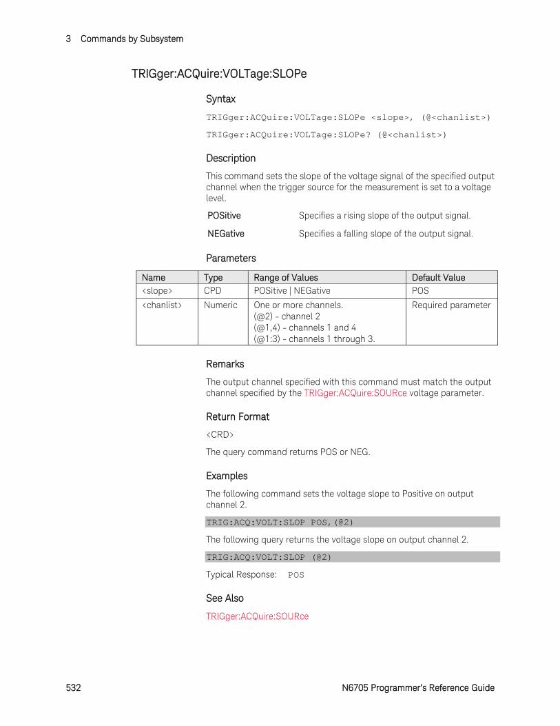
3 Commands by Subsystem
532 N6705 Programmer’s Reference Guide
TRIGger:ACQuire:VOLTage:SLOPe
Syntax
TRIGger:ACQuire:VOLTage:SLOPe <slope>, (@<chanlist>)
TRIGger:ACQuire:VOLTage:SLOPe? (@<chanlist>)
Description
This command sets the slope of the voltage signal of the specified output channel when the trigger source for the measurement is set to a voltage level.
POSitive Specifies a rising slope of the output signal.
NEGative Specifies a falling slope of the output signal.
Parameters
Name Type Range of Values Default Value <slope> CPD POSitive | NEGative POS
<chanlist> Numeric One or more channels. (@2) - channel 2 (@1,4) - channels 1 and 4 (@1:3) - channels 1 through 3.
Required parameter
Remarks
The output channel specified with this command must match the output channel specified by the TRIGger:ACQuire:SOURce voltage parameter.
Return Format
<CRD>
The query command returns POS or NEG.
Examples
The following command sets the voltage slope to Positive on output channel 2.
TRIG:ACQ:VOLT:SLOP POS,(@2)
The following query returns the voltage slope on output channel 2.
TRIG:ACQ:VOLT:SLOP (@2)
Typical Response: POS
See Also
TRIGger:ACQuire:SOURce
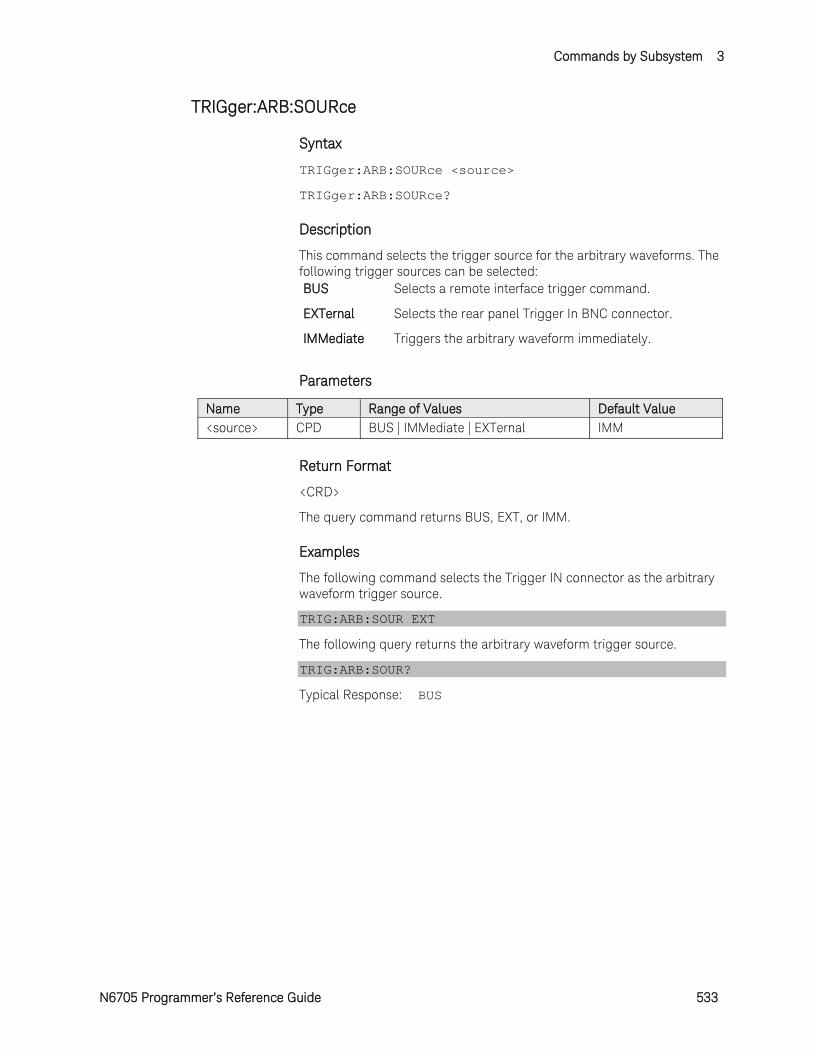
Commands by Subsystem 3
N6705 Programmer’s Reference Guide 533
TRIGger:ARB:SOURce
Syntax
TRIGger:ARB:SOURce <source>
TRIGger:ARB:SOURce?
Description
This command selects the trigger source for the arbitrary waveforms. The following trigger sources can be selected: BUS Selects a remote interface trigger command.
EXTernal Selects the rear panel Trigger In BNC connector.
IMMediate Triggers the arbitrary waveform immediately.
Parameters
Name Type Range of Values Default Value <source> CPD BUS | IMMediate | EXTernal IMM
Return Format
<CRD>
The query command returns BUS, EXT, or IMM.
Examples
The following command selects the Trigger IN connector as the arbitrary waveform trigger source.
TRIG:ARB:SOUR EXT
The following query returns the arbitrary waveform trigger source.
TRIG:ARB:SOUR?
Typical Response: BUS
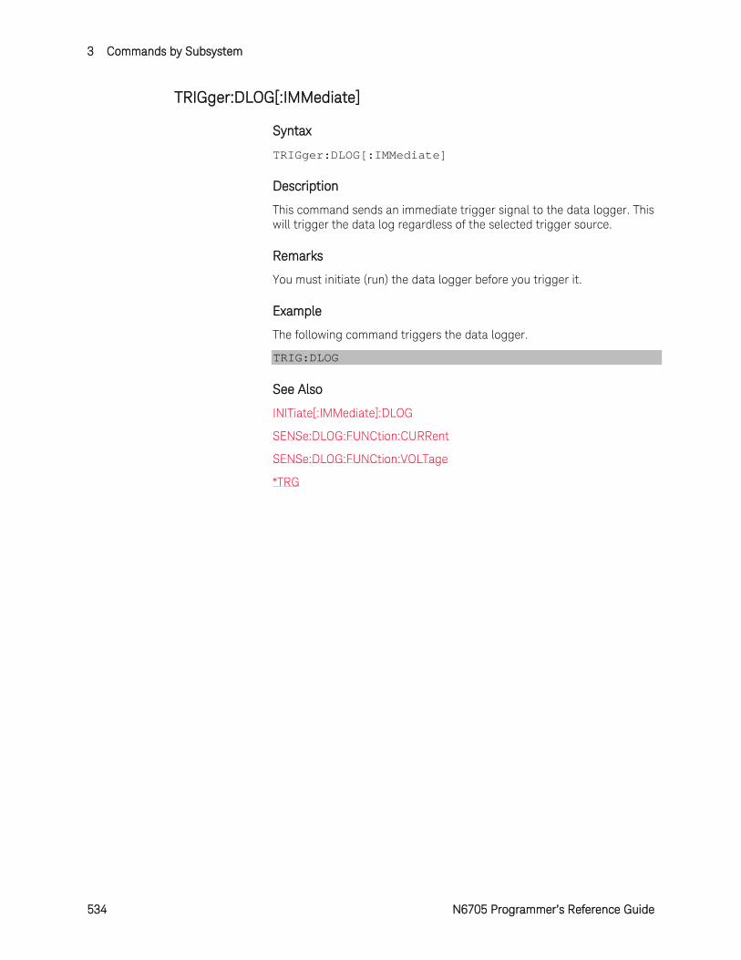
3 Commands by Subsystem
534 N6705 Programmer’s Reference Guide
TRIGger:DLOG[:IMMediate]
Syntax
TRIGger:DLOG[:IMMediate]
Description
This command sends an immediate trigger signal to the data logger. This will trigger the data log regardless of the selected trigger source.
Remarks
You must initiate (run) the data logger before you trigger it.
Example
The following command triggers the data logger.
TRIG:DLOG
See Also
INITiate[:IMMediate]:DLOG
SENSe:DLOG:FUNCtion:CURRent
SENSe:DLOG:FUNCtion:VOLTage
*TRG
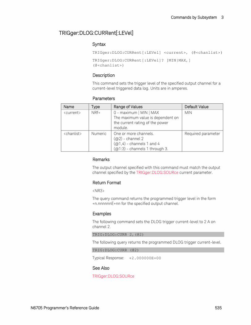
Commands by Subsystem 3
N6705 Programmer’s Reference Guide 535
TRIGger:DLOG:CURRent[:LEVel]
Syntax
TRIGger:DLOG:CURRent[:LEVel] <current>, (@<chanlist>)
TRIGger:DLOG:CURRent[:LEVel]? [MIN|MAX,] (@<chanlist>)
Description
This command sets the trigger level of the specified output channel for a current-level triggered data log. Units are in amperes.
Parameters
Name Type Range of Values Default Value <current> NRf+ 0 - maximum | MIN | MAX
The maximum value is dependent on the current rating of the power module.
MIN
<chanlist> Numeric One or more channels. (@2) - channel 2 (@1,4) - channels 1 and 4 (@1:3) - channels 1 through 3.
Required parameter
Remarks
The output channel specified with this command must match the output channel specified by the TRIGger:DLOG:SOURce current parameter.
Return Format
<NR3>
The query command returns the programmed trigger level in the form +n.nnnnnnE+nn for the specified output channel.
Examples
The following command sets the DLOG trigger current-level to 2 A on channel 2.
TRIG:DLOG:CURR 2,(@2)
The following query returns the programmed DLOG trigger current-level.
TRIG:DLOG:CURR (@2)
Typical Response: +2.000000E+00
See Also
TRIGger:DLOG:SOURce
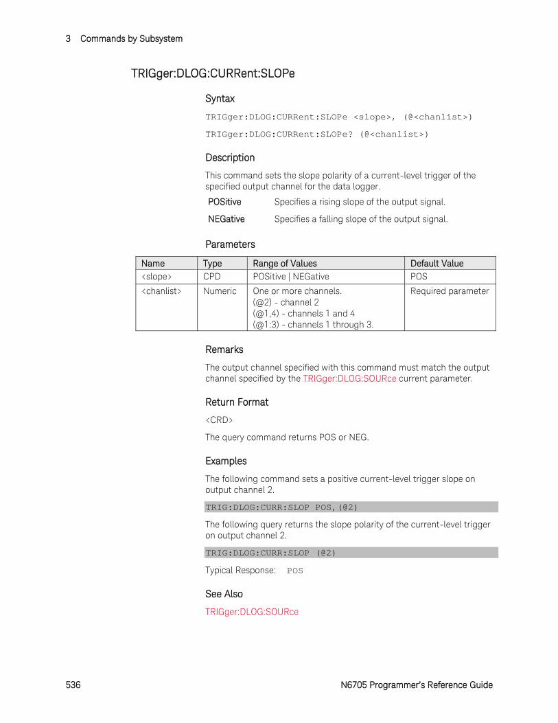
3 Commands by Subsystem
536 N6705 Programmer’s Reference Guide
TRIGger:DLOG:CURRent:SLOPe
Syntax
TRIGger:DLOG:CURRent:SLOPe <slope>, (@<chanlist>)
TRIGger:DLOG:CURRent:SLOPe? (@<chanlist>)
Description
This command sets the slope polarity of a current-level trigger of the specified output channel for the data logger.
POSitive Specifies a rising slope of the output signal.
NEGative Specifies a falling slope of the output signal.
Parameters
Name Type Range of Values Default Value <slope> CPD POSitive | NEGative POS
<chanlist> Numeric One or more channels. (@2) - channel 2 (@1,4) - channels 1 and 4 (@1:3) - channels 1 through 3.
Required parameter
Remarks
The output channel specified with this command must match the output channel specified by the TRIGger:DLOG:SOURce current parameter.
Return Format
<CRD>
The query command returns POS or NEG.
Examples
The following command sets a positive current-level trigger slope on output channel 2.
TRIG:DLOG:CURR:SLOP POS,(@2)
The following query returns the slope polarity of the current-level trigger on output channel 2.
TRIG:DLOG:CURR:SLOP (@2)
Typical Response: POS
See Also
TRIGger:DLOG:SOURce
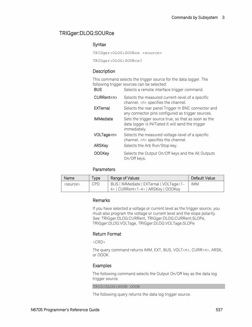
Commands by Subsystem 3
N6705 Programmer’s Reference Guide 537
TRIGger:DLOG:SOURce
Syntax
TRIGger:DLOG:SOURce <source>
TRIGger:DLOG:SOURce?
Description
This command selects the trigger source for the data logger. The following trigger sources can be selected: BUS Selects a remote interface trigger command.
CURRent<n> Selects the measured current-level of a specific channel. <n> specifies the channel.
EXTernal Selects the rear panel Trigger In BNC connector and any connector pins configured as trigger sources.
IMMediate Sets the trigger source true, so that as soon as the data logger is INITiated it will send the trigger immediately.
VOLTage<n> Selects the measured voltage-level of a specific channel. <n> specifies the channel.
ARSKey Selects the Arb Run/Stop key.
OOOKey Selects the Output On/Off keys and the All Outputs On/Off keys.
Parameters
Name Type Range of Values Default Value <source> CPD BUS | IMMediate | EXTernal | VOLTage<1-
4> | CURRent<1-4> | ARSKey | OOOKey IMM
Remarks
If you have selected a voltage or current level as the trigger source, you must also program the voltage or current level and the slope polarity. See: TRIGger:DLOG:CURRent, TRIGger:DLOG:CURRent:SLOPe, TRIGger:DLOG:VOLTage, TRIGger:DLOG:VOLTage:SLOPe
Return Format
<CRD>
The query command returns IMM, EXT, BUS, VOLT<n>, CURR<n>, ARSK, or OOOK.
Examples
The following command selects the Output On/Off key as the data log trigger source.
TRIG:DLOG:SOUR OOOK
The following query returns the data log trigger source.
3 Commands by Subsystem
538 N6705 Programmer’s Reference Guide
TRIG:DLOG:SOUR?
Typical Response: VOLT1
See Also
TRIGger:DLOG:CURRent
TRIGger:DLOG:CURRent:SLOPe
TRIGger:DLOG:VOLTage
TRIGger:DLOG:VOLTage:SLOPe
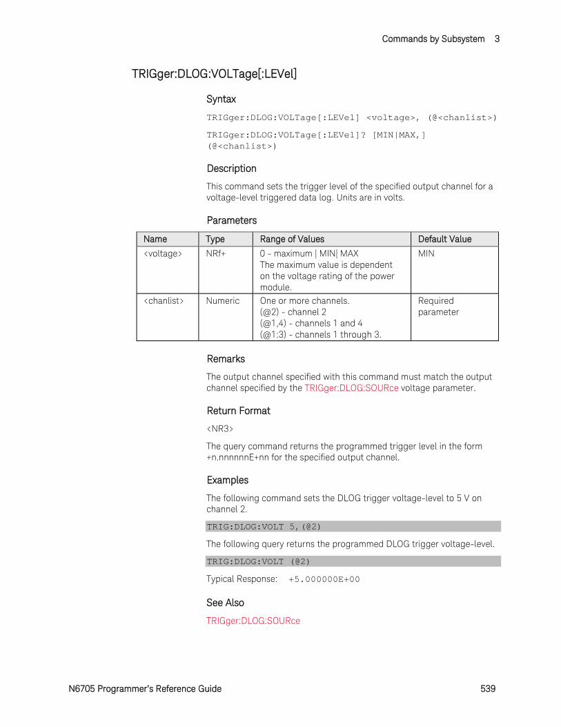
Commands by Subsystem 3
N6705 Programmer’s Reference Guide 539
TRIGger:DLOG:VOLTage[:LEVel]
Syntax
TRIGger:DLOG:VOLTage[:LEVel] <voltage>, (@<chanlist>)
TRIGger:DLOG:VOLTage[:LEVel]? [MIN|MAX,] (@<chanlist>)
Description
This command sets the trigger level of the specified output channel for a voltage-level triggered data log. Units are in volts.
Parameters
Name Type Range of Values Default Value
<voltage> NRf+ 0 - maximum | MIN| MAX The maximum value is dependent on the voltage rating of the power module.
MIN
<chanlist> Numeric One or more channels. (@2) - channel 2 (@1,4) - channels 1 and 4 (@1:3) - channels 1 through 3.
Required parameter
Remarks
The output channel specified with this command must match the output channel specified by the TRIGger:DLOG:SOURce voltage parameter.
Return Format
<NR3>
The query command returns the programmed trigger level in the form +n.nnnnnnE+nn for the specified output channel.
Examples
The following command sets the DLOG trigger voltage-level to 5 V on channel 2.
TRIG:DLOG:VOLT 5,(@2)
The following query returns the programmed DLOG trigger voltage-level.
TRIG:DLOG:VOLT (@2)
Typical Response: +5.000000E+00
See Also
TRIGger:DLOG:SOURce
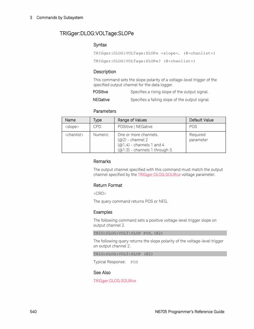
3 Commands by Subsystem
540 N6705 Programmer’s Reference Guide
TRIGger:DLOG:VOLTage:SLOPe
Syntax
TRIGger:DLOG:VOLTage:SLOPe <slope>, (@<chanlist>)
TRIGger:DLOG:VOLTage:SLOPe? (@<chanlist>)
Description
This command sets the slope polarity of a voltage-level trigger of the specified output channel for the data logger.
POSitive Specifies a rising slope of the output signal.
NEGative Specifies a falling slope of the output signal.
Parameters
Name Type Range of Values Default Value
<slope> CPD POSitive | NEGative POS
<chanlist> Numeric One or more channels. (@2) - channel 2 (@1,4) - channels 1 and 4 (@1:3) - channels 1 through 3.
Required parameter
Remarks
The output channel specified with this command must match the output channel specified by the TRIGger:DLOG:SOURce voltage parameter.
Return Format
<CRD>
The query command returns POS or NEG.
Examples
The following command sets a positive voltage-level trigger slope on output channel 2.
TRIG:DLOG:VOLT:SLOP POS,(@2)
The following query returns the slope polarity of the voltage-level trigger on output channel 2.
TRIG:DLOG:VOLT:SLOP (@2)
Typical Response: POS
See Also
TRIGger:DLOG:SOURce
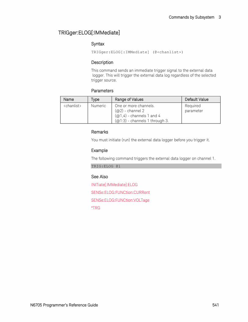
Commands by Subsystem 3
N6705 Programmer’s Reference Guide 541
TRIGger:ELOG[:IMMediate]
Syntax
TRIGger:ELOG[:IMMediate] (@<chanlist>)
Description
This command sends an immediate trigger signal to the external data logger. This will trigger the external data log regardless of the selected trigger source.
Parameters
Name Type Range of Values Default Value
<chanlist> Numeric One or more channels. (@2) - channel 2 (@1,4) - channels 1 and 4 (@1:3) - channels 1 through 3.
Required parameter
Remarks
You must initiate (run) the external data logger before you trigger it.
Example
The following command triggers the external data logger on channel 1.
TRIG:ELOG @1
See Also
INITiate[:IMMediate]:ELOG
SENSe:ELOG:FUNCtion:CURRent
SENSe:ELOG:FUNCtion:VOLTage
*TRG
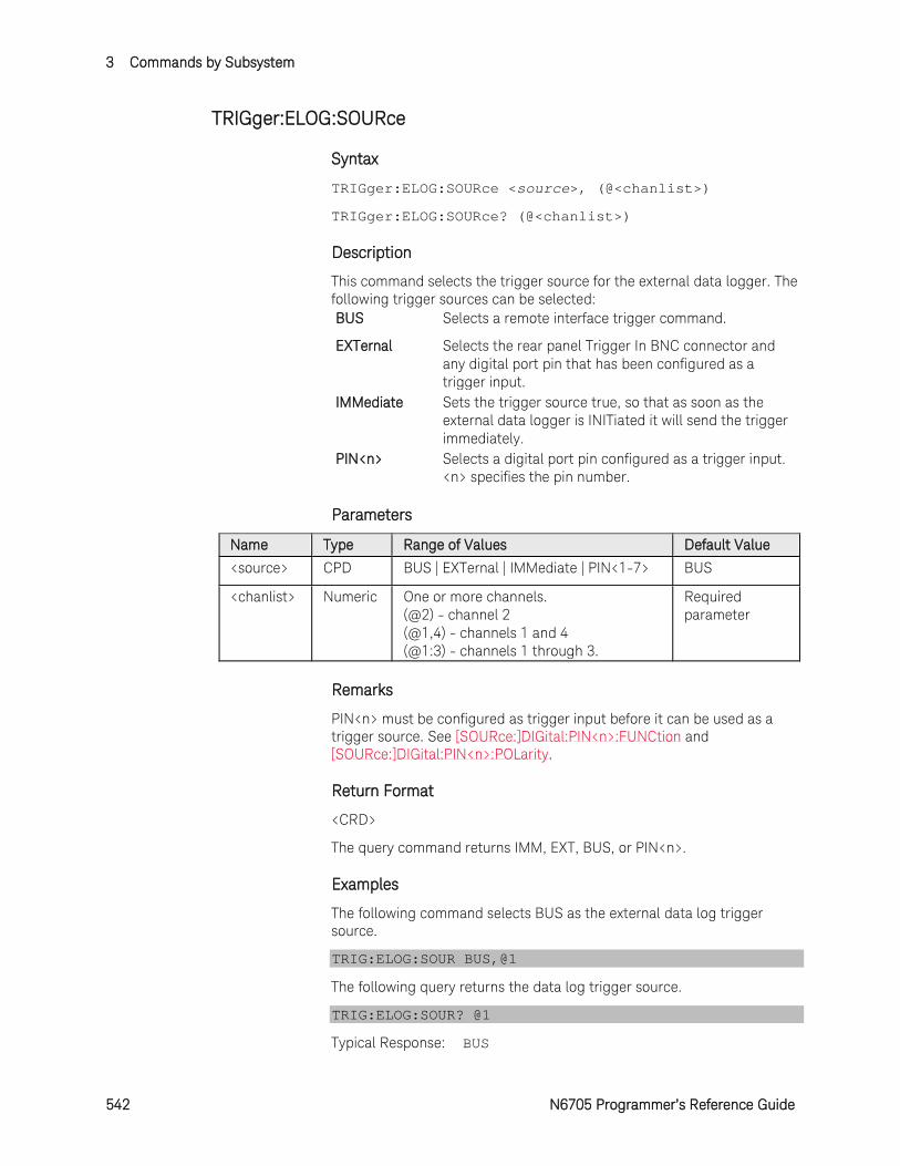
3 Commands by Subsystem
542 N6705 Programmer’s Reference Guide
TRIGger:ELOG:SOURce
Syntax
TRIGger:ELOG:SOURce <source>, (@<chanlist>)
TRIGger:ELOG:SOURce? (@<chanlist>)
Description
This command selects the trigger source for the external data logger. The following trigger sources can be selected: BUS Selects a remote interface trigger command.
EXTernal Selects the rear panel Trigger In BNC connector and any digital port pin that has been configured as a trigger input.
IMMediate Sets the trigger source true, so that as soon as the external data logger is INITiated it will send the trigger immediately.
PIN<n> Selects a digital port pin configured as a trigger input. <n> specifies the pin number.
Parameters
Name Type Range of Values Default Value
<source> CPD BUS | EXTernal | IMMediate | PIN<1-7> BUS
<chanlist> Numeric One or more channels. (@2) - channel 2 (@1,4) - channels 1 and 4 (@1:3) - channels 1 through 3.
Required parameter
Remarks
PIN<n> must be configured as trigger input before it can be used as a trigger source. See [SOURce:]DIGital:PIN<n>:FUNCtion and [SOURce:]DIGital:PIN<n>:POLarity.
Return Format
<CRD>
The query command returns IMM, EXT, BUS, or PIN<n>.
Examples
The following command selects BUS as the external data log trigger source.
TRIG:ELOG:SOUR BUS,@1
The following query returns the data log trigger source.
TRIG:ELOG:SOUR? @1
Typical Response: BUS
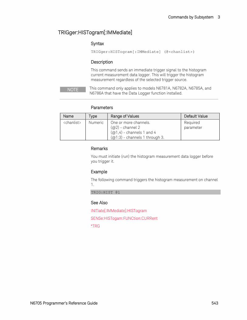
Commands by Subsystem 3
N6705 Programmer’s Reference Guide 543
TRIGger:HISTogram[:IMMediate]
Syntax
TRIGger:HISTogram[:IMMediate] (@<chanlist>)
Description
This command sends an immediate trigger signal to the histogram current measurement data logger. This will trigger the histogram measurement regardless of the selected trigger source.
NOTE This command only applies to models N6781A, N6782A, N6785A, and N6786A that have the Data Logger function installed.
Parameters
Name Type Range of Values Default Value
<chanlist> Numeric One or more channels. (@2) - channel 2 (@1,4) - channels 1 and 4 (@1:3) - channels 1 through 3.
Required parameter
Remarks
You must initiate (run) the histogram measurement data logger before you trigger it.
Example
The following command triggers the histogram measurement on channel 1.
TRIG:HIST @1
See Also
INITiate[:IMMediate]:HISTogram
SENSe:HISTogam:FUNCtion:CURRent
*TRG
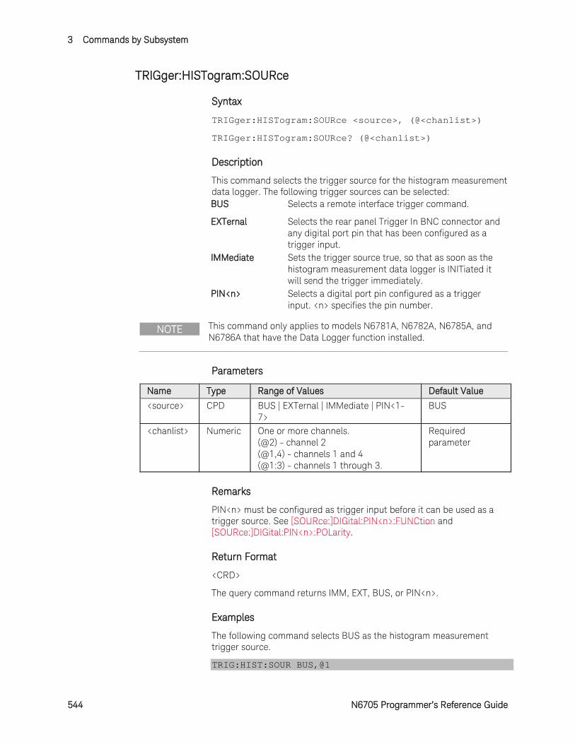
3 Commands by Subsystem
544 N6705 Programmer’s Reference Guide
TRIGger:HISTogram:SOURce
Syntax
TRIGger:HISTogram:SOURce <source>, (@<chanlist>)
TRIGger:HISTogram:SOURce? (@<chanlist>)
Description
This command selects the trigger source for the histogram measurement data logger. The following trigger sources can be selected: BUS Selects a remote interface trigger command.
EXTernal Selects the rear panel Trigger In BNC connector and any digital port pin that has been configured as a trigger input.
IMMediate Sets the trigger source true, so that as soon as the histogram measurement data logger is INITiated it will send the trigger immediately.
PIN<n> Selects a digital port pin configured as a trigger input. <n> specifies the pin number.
NOTE This command only applies to models N6781A, N6782A, N6785A, and N6786A that have the Data Logger function installed.
Parameters
Name Type Range of Values Default Value
<source> CPD BUS | EXTernal | IMMediate | PIN<1-7>
BUS
<chanlist> Numeric One or more channels. (@2) - channel 2 (@1,4) - channels 1 and 4 (@1:3) - channels 1 through 3.
Required parameter
Remarks
PIN<n> must be configured as trigger input before it can be used as a trigger source. See [SOURce:]DIGital:PIN<n>:FUNCtion and [SOURce:]DIGital:PIN<n>:POLarity.
Return Format
<CRD>
The query command returns IMM, EXT, BUS, or PIN<n>.
Examples
The following command selects BUS as the histogram measurement trigger source.
TRIG:HIST:SOUR BUS,@1
Commands by Subsystem 3
N6705 Programmer’s Reference Guide 545
The following query returns the histogram measurement trigger source.
TRIG:HIST:SOUR? @1
Typical Response: BUS
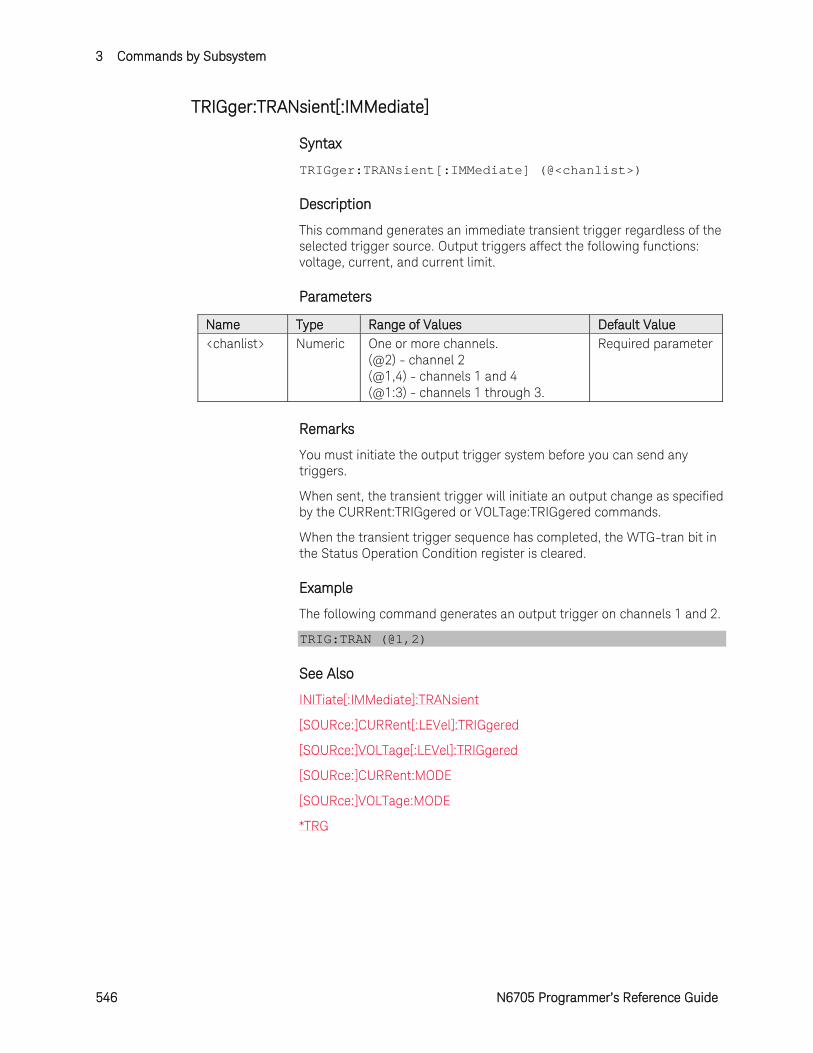
3 Commands by Subsystem
546 N6705 Programmer’s Reference Guide
TRIGger:TRANsient[:IMMediate]
Syntax
TRIGger:TRANsient[:IMMediate] (@<chanlist>)
Description
This command generates an immediate transient trigger regardless of the selected trigger source. Output triggers affect the following functions: voltage, current, and current limit.
Parameters
Name Type Range of Values Default Value <chanlist> Numeric One or more channels.
(@2) - channel 2 (@1,4) - channels 1 and 4 (@1:3) - channels 1 through 3.
Required parameter
Remarks
You must initiate the output trigger system before you can send any triggers.
When sent, the transient trigger will initiate an output change as specified by the CURRent:TRIGgered or VOLTage:TRIGgered commands.
When the transient trigger sequence has completed, the WTG-tran bit in the Status Operation Condition register is cleared.
Example
The following command generates an output trigger on channels 1 and 2.
TRIG:TRAN (@1,2)
See Also
INITiate[:IMMediate]:TRANsient
[SOURce:]CURRent[:LEVel]:TRIGgered
[SOURce:]VOLTage[:LEVel]:TRIGgered
[SOURce:]CURRent:MODE
[SOURce:]VOLTage:MODE
*TRG
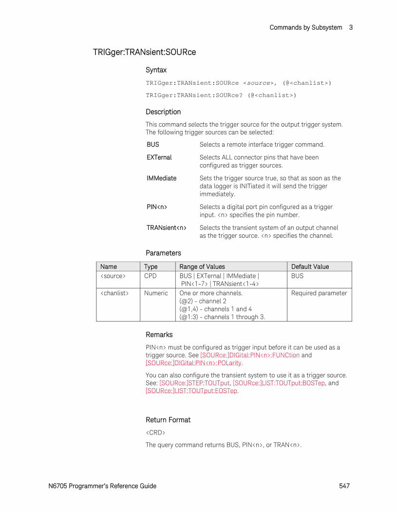
Commands by Subsystem 3
N6705 Programmer’s Reference Guide 547
TRIGger:TRANsient:SOURce
Syntax
TRIGger:TRANsient:SOURce <source>, (@<chanlist>)
TRIGger:TRANsient:SOURce? (@<chanlist>)
Description
This command selects the trigger source for the output trigger system. The following trigger sources can be selected:
BUS Selects a remote interface trigger command.
EXTernal Selects ALL connector pins that have been configured as trigger sources.
IMMediate Sets the trigger source true, so that as soon as the data logger is INITiated it will send the trigger immediately.
PIN<n> Selects a digital port pin configured as a trigger input. <n> specifies the pin number.
TRANsient<n> Selects the transient system of an output channel as the trigger source. <n> specifies the channel.
Parameters
Name Type Range of Values Default Value <source> CPD BUS | EXTernal | IMMediate |
PIN<1-7> | TRANsient<1-4> BUS
<chanlist> Numeric One or more channels. (@2) - channel 2 (@1,4) - channels 1 and 4 (@1:3) - channels 1 through 3.
Required parameter
Remarks
PIN<n> must be configured as trigger input before it can be used as a trigger source. See [SOURce:]DIGital:PIN<n>:FUNCtion and [SOURce:]DIGital:PIN<n>:POLarity.
You can also configure the transient system to use it as a trigger source. See: [SOURce:]STEP:TOUTput, [SOURce:]LIST:TOUTput:BOSTep, and [SOURce:]LIST:TOUTput:EOSTep.
Return Format
<CRD>
The query command returns BUS, PIN<n>, or TRAN<n>.

3 Commands by Subsystem
548 N6705 Programmer’s Reference Guide
Examples
The following command selects pin 1 as the output trigger source for channel 2.
TRIG:TRAN:SOUR PIN1,(@2)
The following query returns the output trigger source of channel 1.
TRIG:TRAN:SOUR? (@1)
Typical Response: BUS
See Also
[SOURce:]DIGital:PIN<1-7>:FUNCtion
[SOURce:]DIGital:PIN<1-7>:POLarity
[SOURce:]STEP:TOUTput
[SOURce:]LIST:TOUTput:BOSTep
[SOURce:]LIST:TOUTput:EOSTep
N6705 Programmer’s Reference Guide 549
4 Command Quick Reference
SCPI Command Summary ........................................................... 550 Non-Volatile Settings ................................................................... 559 Reset Settings (*RST) ................................................................... 560 Keysight N678xA Initial Emulation Mode Settings ...................... 562
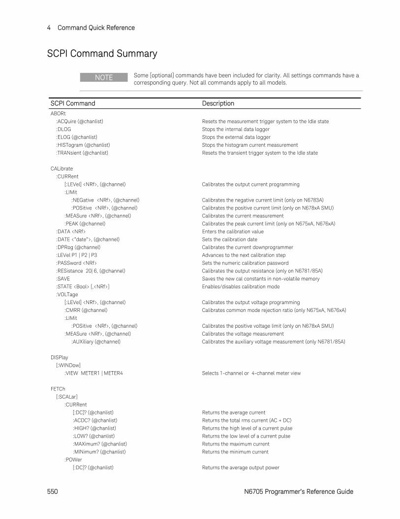
4 Command Quick Reference
550 N6705 Programmer’s Reference Guide
SCPI Command Summary
NOTE Some [optional] commands have been included for clarity. All settings commands have a corresponding query. Not all commands apply to all models.
SCPI Command Description
ABORt
:ACQuire (@chanlist) Resets the measurement trigger system to the Idle state
:DLOG Stops the internal data logger
:ELOG (@chanlist) Stops the external data logger
:HISTogram (@chanlist) Stops the histogram current measurement
:TRANsient (@chanlist) Resets the transient trigger system to the Idle state
CALibrate
:CURRent
[:LEVel] <NRf>, (@channel) Calibrates the output current programming
:LIMit
:NEGative <NRf>, (@channel) Calibrates the negative current limit (only on N6783A)
:POSitive <NRf>, (@channel) Calibrates the positive current limit (only on N678xA SMU)
:MEASure <NRf>, (@channel) Calibrates the current measurement
:PEAK (@channel) Calibrates the peak current limit (only on N675xA, N676xA)
:DATA <NRf> Enters the calibration value
:DATE <”date”>, (@channel) Sets the calibration date
:DPRog (@channel) Calibrates the current downprogrammer
:LEVel P1 | P2 | P3 Advances to the next calibration step
:PASSword <NRf> Sets the numeric calibration password
:RESistance 20| 6, (@channel) Calibrates the output resistance (only on N6781/85A)
:SAVE Saves the new cal constants in non-volatile memory
:STATE <Bool> [,<NRf>] Enables/disables calibration mode
:VOLTage
[:LEVel] <NRf>, (@channel) Calibrates the output voltage programming
:CMRR (@channel) Calibrates common mode rejection ratio (only N675xA, N676xA)
:LIMit
:POSitive <NRf>, (@channel) Calibrates the positive voltage limit (only on N678xA SMU)
:MEASure <NRf>, (@channel) Calibrates the voltage measurement
:AUXiliary (@channel) Calibrates the auxiliary voltage measurement (only N6781/85A)
DISPlay
[:WINDow]
:VIEW METER1 | METER4 Selects 1-channel or 4-channel meter view
FETCh
[:SCALar]
:CURRent
[:DC]? (@chanlist) Returns the average current
:ACDC? (@chanlist) Returns the total rms current (AC + DC)
:HIGH? (@chanlist) Returns the high level of a current pulse
:LOW? (@chanlist) Returns the low level of a current pulse
:MAXimum? (@chanlist) Returns the maximum current
:MINimum? (@chanlist) Returns the minimum current
:POWer
[:DC]? (@chanlist) Returns the average output power
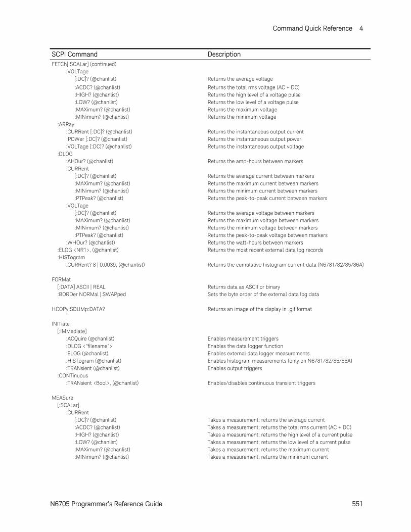
Command Quick Reference 4
N6705 Programmer’s Reference Guide 551
SCPI Command Description FETCh[:SCALar] (continued) :VOLTage [:DC]? (@chanlist) Returns the average voltage
:ACDC? (@chanlist) Returns the total rms voltage (AC + DC) :HIGH? (@chanlist) Returns the high level of a voltage pulse :LOW? (@chanlist) Returns the low level of a voltage pulse :MAXimum? (@chanlist) Returns the maximum voltage :MINimum? (@chanlist) Returns the minimum voltage :ARRay :CURRent [:DC]? (@chanlist) Returns the instantaneous output current :POWer [:DC]? (@chanlist) Returns the instantaneous output power :VOLTage [:DC]? (@chanlist) Returns the instantaneous output voltage :DLOG :AHOur? (@chanlist) Returns the amp-hours between markers :CURRent [:DC]? (@chanlist) Returns the average current between markers :MAXimum? (@chanlist) Returns the maximum current between markers :MINimum? (@chanlist) Returns the minimum current between markers :PTPeak? (@chanlist) Returns the peak-to-peak current between markers :VOLTage [:DC]? (@chanlist) Returns the average voltage between markers :MAXimum? (@chanlist) Returns the maximum voltage between markers :MINimum? (@chanlist) Returns the minimum voltage between markers :PTPeak? (@chanlist) Returns the peak-to-peak voltage between markers :WHOur? (@chanlist) Returns the watt-hours between markers :ELOG <NR1>, (@chanlist) Returns the most recent external data log records :HISTogram :CURRent? 8 | 0.0039, (@chanlist) Returns the cumulative histogram current data (N6781/82/85/86A) FORMat [:DATA] ASCII | REAL Returns data as ASCII or binary :BORDer NORMal | SWAPped Sets the byte order of the external data log data HCOPy:SDUMp:DATA? Returns an image of the display in .gif format INITiate [:IMMediate] :ACQuire (@chanlist) Enables measurement triggers :DLOG <“filename”> Enables the data logger function :ELOG (@chanlist) Enables external data logger measurements :HISTogram (@chanlist) Enables histogram measurements (only on N6781/82/85/86A) :TRANsient (@chanlist) Enables output triggers :CONTinuous :TRANsient <Bool>, (@chanlist) Enables/disables continuous transient triggers MEASure [:SCALar] :CURRent [:DC]? (@chanlist) Takes a measurement; returns the average current :ACDC? (@chanlist) Takes a measurement; returns the total rms current (AC + DC) :HIGH? (@chanlist) Takes a measurement; returns the high level of a current pulse :LOW? (@chanlist) Takes a measurement; returns the low level of a current pulse :MAXimum? (@chanlist) Takes a measurement; returns the maximum current :MINimum? (@chanlist) Takes a measurement; returns the minimum current
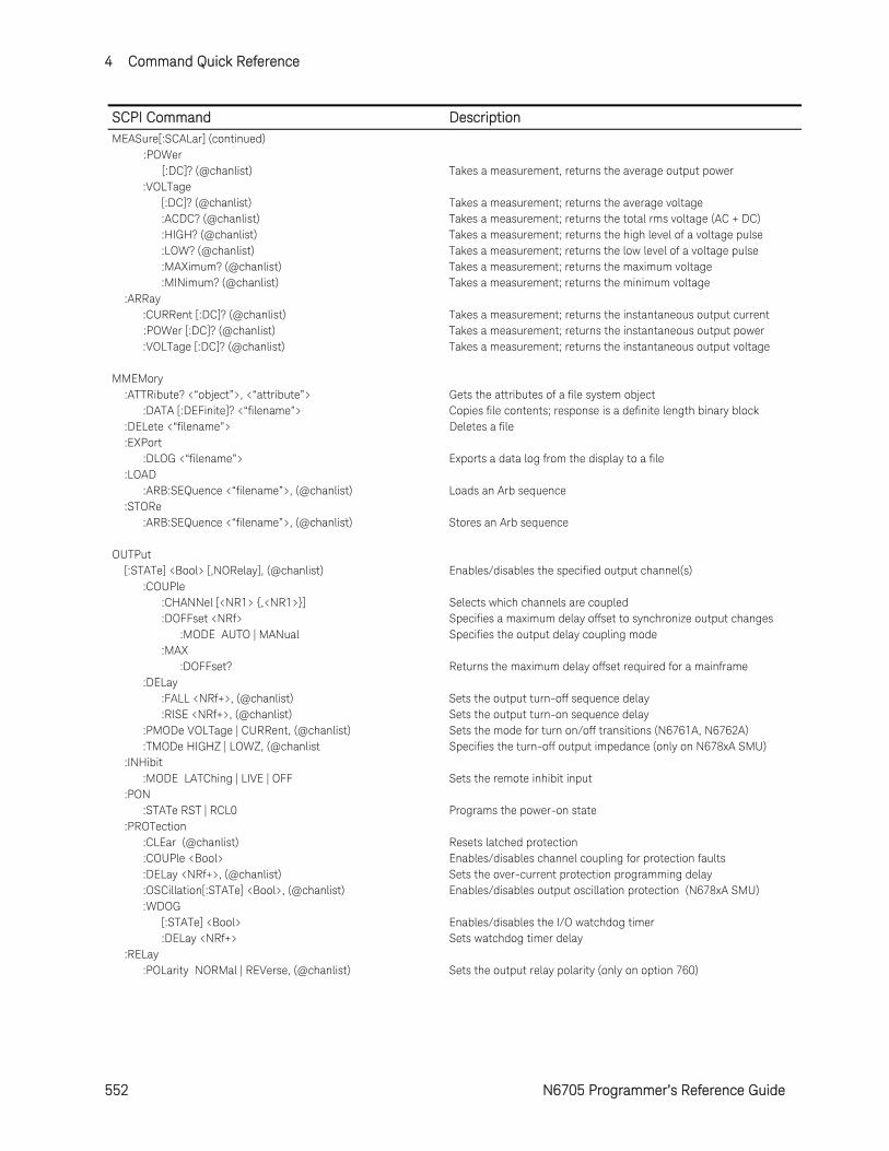
4 Command Quick Reference
552 N6705 Programmer’s Reference Guide
SCPI Command Description MEASure[:SCALar] (continued) :POWer [:DC]? (@chanlist) Takes a measurement, returns the average output power :VOLTage [:DC]? (@chanlist) Takes a measurement; returns the average voltage :ACDC? (@chanlist) Takes a measurement; returns the total rms voltage (AC + DC) :HIGH? (@chanlist) Takes a measurement; returns the high level of a voltage pulse :LOW? (@chanlist) Takes a measurement; returns the low level of a voltage pulse :MAXimum? (@chanlist) Takes a measurement; returns the maximum voltage :MINimum? (@chanlist) Takes a measurement; returns the minimum voltage :ARRay :CURRent [:DC]? (@chanlist) Takes a measurement; returns the instantaneous output current :POWer [:DC]? (@chanlist) Takes a measurement; returns the instantaneous output power :VOLTage [:DC]? (@chanlist) Takes a measurement; returns the instantaneous output voltage MMEMory :ATTRibute? <“object”>, <“attribute”> Gets the attributes of a file system object :DATA [:DEFinite]? <“filename”> Copies file contents; response is a definite length binary block :DELete <“filename”> Deletes a file :EXPort :DLOG <“filename”> Exports a data log from the display to a file :LOAD :ARB:SEQuence <“filename”>, (@chanlist) Loads an Arb sequence :STORe :ARB:SEQuence <“filename”>, (@chanlist) Stores an Arb sequence OUTPut [:STATe] <Bool> [,NORelay], (@chanlist) Enables/disables the specified output channel(s) :COUPle :CHANNel [<NR1> ,<NR1>] Selects which channels are coupled :DOFFset <NRf> Specifies a maximum delay offset to synchronize output changes :MODE AUTO | MANual Specifies the output delay coupling mode :MAX :DOFFset? Returns the maximum delay offset required for a mainframe :DELay :FALL <NRf+>, (@chanlist) Sets the output turn-off sequence delay :RISE <NRf+>, (@chanlist) Sets the output turn-on sequence delay :PMODe VOLTage | CURRent, (@chanlist) Sets the mode for turn on/off transitions (N6761A, N6762A) :TMODe HIGHZ | LOWZ, (@chanlist Specifies the turn-off output impedance (only on N678xA SMU) :INHibit :MODE LATChing | LIVE | OFF Sets the remote inhibit input :PON :STATe RST | RCL0 Programs the power-on state :PROTection :CLEar (@chanlist) Resets latched protection :COUPle <Bool> Enables/disables channel coupling for protection faults :DELay <NRf+>, (@chanlist) Sets the over-current protection programming delay :OSCillation[:STATe] <Bool>, (@chanlist) Enables/disables output oscillation protection (N678xA SMU) :WDOG [:STATe] <Bool> Enables/disables the I/O watchdog timer :DELay <NRf+> Sets watchdog timer delay :RELay :POLarity NORMal | REVerse, (@chanlist) Sets the output relay polarity (only on option 760)
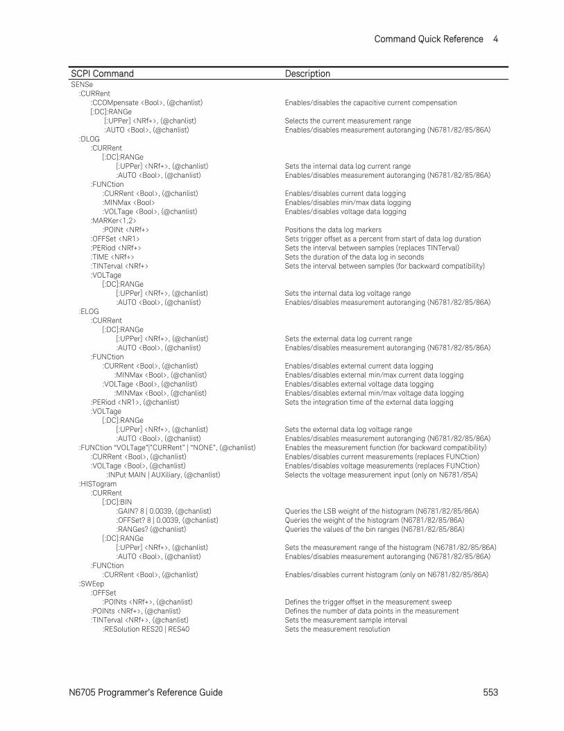
Command Quick Reference 4
N6705 Programmer’s Reference Guide 553
SCPI Command DescriptionSENSe :CURRent :CCOMpensate <Bool>, (@chanlist) Enables/disables the capacitive current compensation [:DC]:RANGe [:UPPer] <NRf+>, (@chanlist) Selects the current measurement range :AUTO <Bool>, (@chanlist) Enables/disables measurement autoranging (N6781/82/85/86A) :DLOG :CURRent [:DC]:RANGe [:UPPer] <NRf+>, (@chanlist) Sets the internal data log current range :AUTO <Bool>, (@chanlist) Enables/disables measurement autoranging (N6781/82/85/86A) :FUNCtion :CURRent <Bool>, (@chanlist) Enables/disables current data logging :MINMax <Bool> Enables/disables min/max data logging :VOLTage <Bool>, (@chanlist) Enables/disables voltage data logging :MARKer<1,2> :POINt <NRf+> Positions the data log markers :OFFSet <NR1> Sets trigger offset as a percent from start of data log duration :PERiod <NRf+> Sets the interval between samples (replaces TINTerval) :TIME <NRf+> Sets the duration of the data log in seconds :TINTerval <NRf+> Sets the interval between samples (for backward compatibility) :VOLTage [:DC]:RANGe [:UPPer] <NRf+>, (@chanlist) Sets the internal data log voltage range :AUTO <Bool>, (@chanlist) Enables/disables measurement autoranging (N6781/82/85/86A) :ELOG :CURRent [:DC]:RANGe [:UPPer] <NRf+>, (@chanlist) Sets the external data log current range :AUTO <Bool>, (@chanlist) Enables/disables measurement autoranging (N6781/82/85/86A) :FUNCtion :CURRent <Bool>, (@chanlist) Enables/disables external current data logging :MINMax <Bool>, (@chanlist) Enables/disables external min/max current data logging :VOLTage <Bool>, (@chanlist) Enables/disables external voltage data logging :MINMax <Bool>, (@chanlist) Enables/disables external min/max voltage data logging :PERiod <NR1>, (@chanlist) Sets the integration time of the external data logging :VOLTage [:DC]:RANGe [:UPPer] <NRf+>, (@chanlist) Sets the external data log voltage range :AUTO <Bool>, (@chanlist) Enables/disables measurement autoranging (N6781/82/85/86A) :FUNCtion “VOLTage”|”CURRent” | “NONE”, (@chanlist) Enables the measurement function (for backward compatibility) :CURRent <Bool>, (@chanlist) Enables/disables current measurements (replaces FUNCtion) :VOLTage <Bool>, (@chanlist) Enables/disables voltage measurements (replaces FUNCtion) :INPut MAIN | AUXiliary, (@chanlist) Selects the voltage measurement input (only on N6781/85A) :HISTogram :CURRent [:DC]:BIN :GAIN? 8 | 0.0039, (@chanlist) Queries the LSB weight of the histogram (N6781/82/85/86A) :OFFSet? 8 | 0.0039, (@chanlist) Queries the weight of the histogram (N6781/82/85/86A) :RANGes? (@chanlist) Queries the values of the bin ranges (N6781/82/85/86A) [:DC]:RANGe [:UPPer] <NRf+>, (@chanlist) Sets the measurement range of the histogram (N6781/82/85/86A) :AUTO <Bool>, (@chanlist) Enables/disables measurement autoranging (N6781/82/85/86A) :FUNCtion :CURRent <Bool>, (@chanlist) Enables/disables current histogram (only on N6781/82/85/86A) :SWEep :OFFSet :POINts <NRf+>, (@chanlist) Defines the trigger offset in the measurement sweep :POINts <NRf+>, (@chanlist) Defines the number of data points in the measurement :TINTerval <NRf+>, (@chanlist) Sets the measurement sample interval :RESolution RES20 | RES40 Sets the measurement resolution
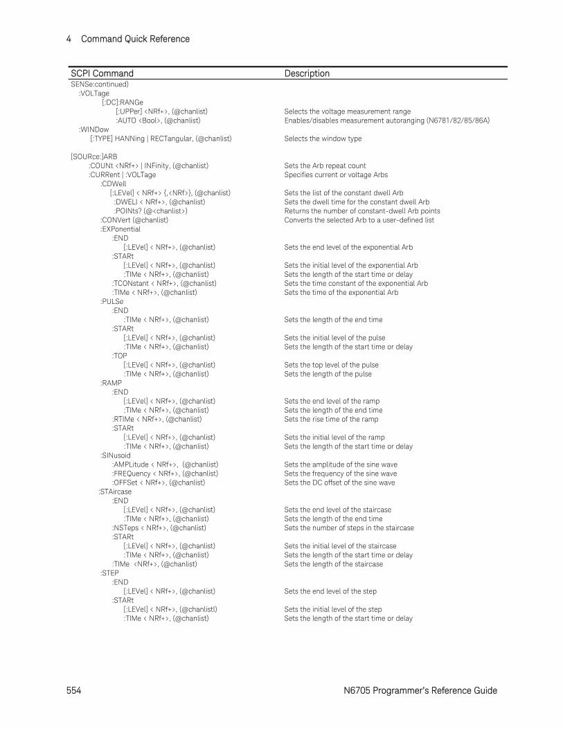
4 Command Quick Reference
554 N6705 Programmer’s Reference Guide
SCPI Command DescriptionSENSe:continued) :VOLTage [:DC]:RANGe [:UPPer] <NRf+>, (@chanlist) Selects the voltage measurement range :AUTO <Bool>, (@chanlist) Enables/disables measurement autoranging (N6781/82/85/86A) :WINDow [:TYPE] HANNing | RECTangular, (@chanlist) Selects the window type [SOURce:]ARB :COUNt <NRf+> | INFinity, (@chanlist) Sets the Arb repeat count :CURRent | :VOLTage Specifies current or voltage Arbs :CDWell [:LEVel] < NRf+> ,<NRf>, (@chanlist) Sets the list of the constant dwell Arb :DWELl < NRf+>, (@chanlist) Sets the dwell time for the constant dwell Arb :POINts? (@<chanlist>) Returns the number of constant-dwell Arb points :CONVert (@chanlist) Converts the selected Arb to a user-defined list :EXPonential :END [:LEVel] < NRf+>, (@chanlist) Sets the end level of the exponential Arb :STARt [:LEVel] < NRf+>, (@chanlist) Sets the initial level of the exponential Arb :TIMe < NRf+>, (@chanlist) Sets the length of the start time or delay :TCONstant < NRf+>, (@chanlist) Sets the time constant of the exponential Arb :TIMe < NRf+>, (@chanlist) Sets the time of the exponential Arb :PULSe :END :TIMe < NRf+>, (@chanlist) Sets the length of the end time :STARt [:LEVel] < NRf+>, (@chanlist) Sets the initial level of the pulse :TIMe < NRf+>, (@chanlist) Sets the length of the start time or delay :TOP [:LEVel] < NRf+>, (@chanlist) Sets the top level of the pulse :TIMe < NRf+>, (@chanlist) Sets the length of the pulse :RAMP :END [:LEVel] < NRf+>, (@chanlist) Sets the end level of the ramp :TIMe < NRf+>, (@chanlist) Sets the length of the end time :RTIMe < NRf+>, (@chanlist) Sets the rise time of the ramp :STARt [:LEVel] < NRf+>, (@chanlist) Sets the initial level of the ramp :TIMe < NRf+>, (@chanlist) Sets the length of the start time or delay :SINusoid :AMPLitude < NRf+>, (@chanlist) Sets the amplitude of the sine wave :FREQuency < NRf+>, (@chanlist) Sets the frequency of the sine wave :OFFSet < NRf+>, (@chanlist) Sets the DC offset of the sine wave :STAircase :END [:LEVel] < NRf+>, (@chanlist) Sets the end level of the staircase :TIMe < NRf+>, (@chanlist) Sets the length of the end time :NSTeps < NRf+>, (@chanlist) Sets the number of steps in the staircase :STARt [:LEVel] < NRf+>, (@chanlist) Sets the initial level of the staircase :TIMe < NRf+>, (@chanlist) Sets the length of the start time or delay :TIMe <NRf+>, (@chanlist) Sets the length of the staircase :STEP :END [:LEVel] < NRf+>, (@chanlist) Sets the end level of the step :STARt [:LEVel] < NRf+>, (@chanlistl) Sets the initial level of the step :TIMe < NRf+>, (@chanlist) Sets the length of the start time or delay
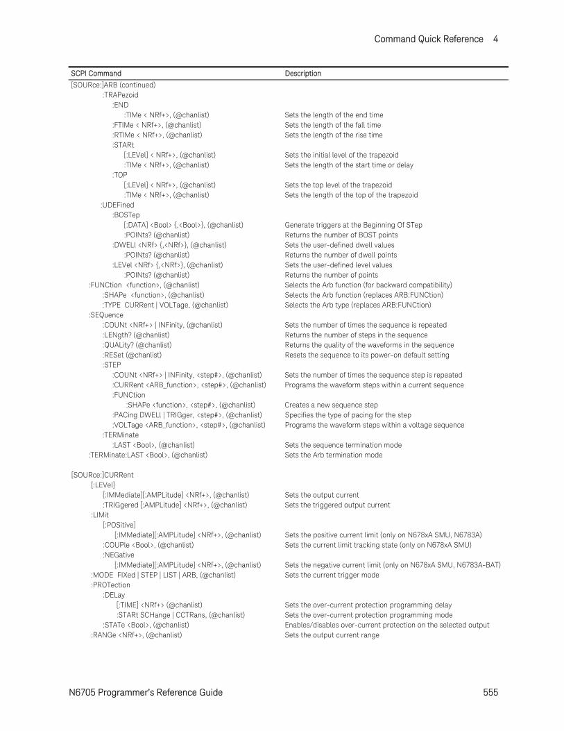
Command Quick Reference 4
N6705 Programmer’s Reference Guide 555
SCPI Command Description
[SOURce:]ARB (continued) :TRAPezoid :END :TIMe < NRf+>, (@chanlist) Sets the length of the end time :FTIMe < NRf+>, (@chanlist) Sets the length of the fall time :RTIMe < NRf+>, (@chanlist) Sets the length of the rise time :STARt [:LEVel] < NRf+>, (@chanlist) Sets the initial level of the trapezoid :TIMe < NRf+>, (@chanlist) Sets the length of the start time or delay :TOP [:LEVel] < NRf+>, (@chanlist) Sets the top level of the trapezoid :TIMe < NRf+>, (@chanlist) Sets the length of the top of the trapezoid :UDEFined :BOSTep [:DATA] <Bool> ,<Bool>, (@chanlist) Generate triggers at the Beginning Of STep :POINts? (@chanlist) Returns the number of BOST points :DWELl <NRf> ,<NRf>, (@chanlist) Sets the user-defined dwell values :POINts? (@chanlist) Returns the number of dwell points :LEVel <NRf> ,<NRf>, (@chanlist) Sets the user-defined level values :POINts? (@chanlist) Returns the number of points :FUNCtion <function>, (@chanlist) Selects the Arb function (for backward compatibility) :SHAPe <function>, (@chanlist) Selects the Arb function (replaces ARB:FUNCtion) :TYPE CURRent | VOLTage, (@chanlist) Selects the Arb type (replaces ARB:FUNCtion) :SEQuence :COUNt <NRf+> | INFinity, (@chanlist) Sets the number of times the sequence is repeated :LENgth? (@chanlist) Returns the number of steps in the sequence :QUALity? (@chanlist) Returns the quality of the waveforms in the sequence :RESet (@chanlist) Resets the sequence to its power-on default setting :STEP :COUNt <NRf+> | INFinity, <step#>, (@chanlist) Sets the number of times the sequence step is repeated :CURRent <ARB_function>, <step#>, (@chanlist) Programs the waveform steps within a current sequence :FUNCtion :SHAPe <function>, <step#>, (@chanlist) Creates a new sequence step :PACing DWELl | TRIGger, <step#>, (@chanlist) Specifies the type of pacing for the step :VOLTage <ARB_function>, <step#>, (@chanlist) Programs the waveform steps within a voltage sequence :TERMinate :LAST <Bool>, (@chanlist) Sets the sequence termination mode :TERMinate:LAST <Bool>, (@chanlist) Sets the Arb termination mode [SOURce:]CURRent [:LEVel] [:IMMediate][:AMPLitude] <NRf+>, (@chanlist) Sets the output current :TRIGgered [:AMPLitude] <NRf+>, (@chanlist) Sets the triggered output current :LIMit [:POSitive] [:IMMediate][:AMPLitude] <NRf+>, (@chanlist) Sets the positive current limit (only on N678xA SMU, N6783A) :COUPle <Bool>, (@chanlist) Sets the current limit tracking state (only on N678xA SMU) :NEGative [:IMMediate][:AMPLitude] <NRf+>, (@chanlist) Sets the negative current limit (only on N678xA SMU, N6783A-BAT) :MODE FIXed | STEP | LIST | ARB, (@chanlist) Sets the current trigger mode :PROTection :DELay [:TIME] <NRf+> (@chanlist) Sets the over-current protection programming delay :STARt SCHange | CCTRans, (@chanlist) Sets the over-current protection programming mode :STATe <Bool>, (@chanlist) Enables/disables over-current protection on the selected output :RANGe <NRf+>, (@chanlist) Sets the output current range
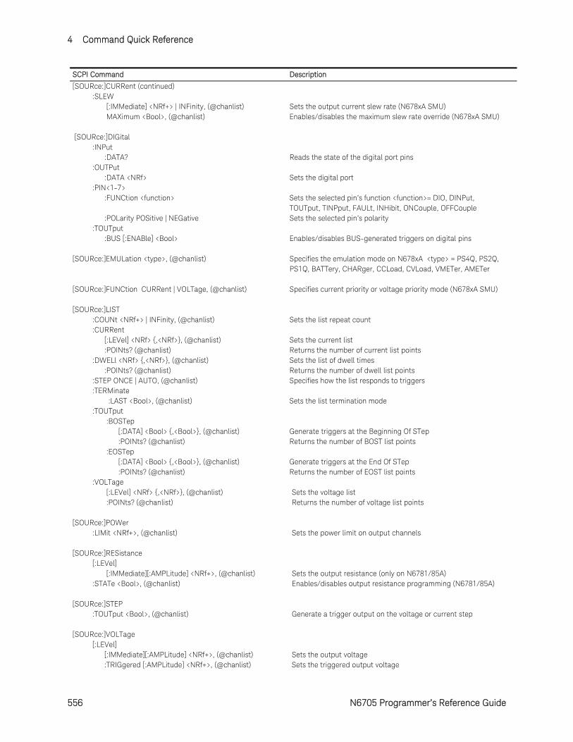
4 Command Quick Reference
556 N6705 Programmer’s Reference Guide
SCPI Command Description
[SOURce:]CURRent (continued) :SLEW [:IMMediate] <NRf+> | INFinity, (@chanlist) Sets the output current slew rate (N678xA SMU) MAXimum <Bool>, (@chanlist) Enables/disables the maximum slew rate override (N678xA SMU) [SOURce:]DIGital :INPut :DATA? Reads the state of the digital port pins :OUTPut :DATA <NRf> Sets the digital port :PIN<1-7> :FUNCtion <function> Sets the selected pin’s function <function>= DIO, DINPut, TOUTput, TINPput, FAULt, INHibit, ONCouple, OFFCouple :POLarity POSitive | NEGative Sets the selected pin’s polarity :TOUTput :BUS [:ENABle] <Bool> Enables/disables BUS-generated triggers on digital pins [SOURce:]EMULation <type>, (@chanlist) Specifies the emulation mode on N678xA <type> = PS4Q, PS2Q, PS1Q, BATTery, CHARger, CCLoad, CVLoad, VMETer, AMETer [SOURce:]FUNCtion CURRent | VOLTage, (@chanlist) Specifies current priority or voltage priority mode (N678xA SMU) [SOURce:]LIST :COUNt <NRf+> | INFinity, (@chanlist) Sets the list repeat count :CURRent [:LEVel] <NRf> ,<NRf>, (@chanlist) Sets the current list :POINts? (@chanlist) Returns the number of current list points :DWELl <NRf> ,<NRf>, (@chanlist) Sets the list of dwell times :POINts? (@chanlist) Returns the number of dwell list points :STEP ONCE | AUTO, (@chanlist) Specifies how the list responds to triggers :TERMinate :LAST <Bool>, (@chanlist) Sets the list termination mode :TOUTput :BOSTep [:DATA] <Bool> ,<Bool>, (@chanlist) Generate triggers at the Beginning Of STep :POINts? (@chanlist) Returns the number of BOST list points :EOSTep [:DATA] <Bool> ,<Bool>, (@chanlist) Generate triggers at the End Of STep :POINts? (@chanlist) Returns the number of EOST list points :VOLTage [:LEVel] <NRf> ,<NRf>, (@chanlist) Sets the voltage list :POINts? (@chanlist) Returns the number of voltage list points [SOURce:]POWer :LIMit <NRf+>, (@chanlist) Sets the power limit on output channels [SOURce:]RESistance [:LEVel] [:IMMediate][:AMPLitude] <NRf+>, (@chanlist) Sets the output resistance (only on N6781/85A) :STATe <Bool>, (@chanlist) Enables/disables output resistance programming (N6781/85A) [SOURce:]STEP :TOUTput <Bool>, (@chanlist) Generate a trigger output on the voltage or current step [SOURce:]VOLTage [:LEVel] [:IMMediate][:AMPLitude] <NRf+>, (@chanlist) Sets the output voltage :TRIGgered [:AMPLitude] <NRf+>, (@chanlist) Sets the triggered output voltage
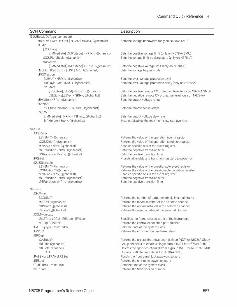
Command Quick Reference 4
N6705 Programmer’s Reference Guide 557
SCPI Command Description [SOURce:]VOLTage (continued) :BWIDth LOW | HIGH1 | HIGH2 | HIGH3, (@chanlist) Sets the voltage bandwidth (only on N678xA SMU) :LIMit [:POSitive] [:IMMediate][:AMPLitude] <NRf+>, (@chanlist) Sets the positive voltage limit (only on N678xA SMU) :COUPle <Bool>, (@chanlist) Sets the voltage limit tracking state (only on N6784A) :NEGative [:IMMediate][:AMPLitude] <NRf+>, (@chanlist) Sets the negative voltage limit (only on N6784A) :MODE FIXed | STEP | LIST | ARB, (@chanlist) Sets the voltage trigger mode :PROTection [:LEVel] <NRf+>, (@chanlist) Sets the over-voltage protection level :DELay[:TIME] <NRf+>, (@chanlist) Sets the over-voltage protection delay (only on N6783A) :REMote [:POSitive][:LEVel] <NRf+>, (@chanlist) Sets the positive remote OV protection level (only on N678xA SMU) :NEGative[:LEVel] <NRf+>, (@chanlist) Sets the negative remote OV protection level (only on N6784A) :RANGe <NRf+>, (@chanlist) Sets the output voltage range :SENSe :SOURce INTernal | EXTernal, (@chanlist) Sets the remote sense relays :SLEW [:IMMediate] <NRf+> | INFinity, (@chanlist) Sets the output voltage slew rate MAXimum <Bool>, (@chanlist) Enables/disables the maximum slew rate override STATus :OPERation [:EVENt]? (@chanlist) Returns the value of the operation event register :CONDition? (@chanlist) Returns the value of the operation condition register :ENABle <NRf>, (@chanlist) Enables specific bits in the event register :NTRansition <NRf>, (@chanlist) Sets the negative transition filter :PTRansition <NRf>, (@chanlist) Sets the positive transition filter :PRESet Presets all enable and transition registers to power-on :QUEStionable [:EVENt]? (@chanlist) Returns the value of the questionable event register :CONDition? (@chanlist) Returns the value of the questionable condition register :ENABle <NRf>, (@chanlist) Enables specific bits in the event register :NTRansition <NRf>, (@chanlist) Sets the negative transition filter :PTRansition <NRf>, (@chanlist) Sets the positive transition filter SYSTem :CHANnel [:COUNt]? Returns the number of output channels in a mainframe :MODel? (@chanlist) Returns the model number of the selected channel :OPTion? (@chanlist) Returns the option installed in the selected channel :SERial? (@chanlist) Returns the serial number of the selected channel :COMMunicate :RLSTate LOCal | REMote | RWLock Specifies the Remote/Local state of the instrument :TCPip:CONTrol? Returns the control connection port number :DATE <yyyy>,<mm>,<dd> Sets the date of the system clock :ERRor? Returns the error number and error string :GROup :CATalog? Returns the groups that have been defined (NOT for N678xA SMU) :DEFine (@chanlist) Group channels to create a single output (NOT for N678xA SMU) :DELete <channel> Deletes the specified channel from a group (NOT for N678xA SMU) :ALL Ungroups all channels (NOT for N678xA SMU) :PASSword:FPANel:RESet Resets the front panel lock password to zero :REBoot Returns the unit to its power-on state :TIME <hh>,<mm>,<ss> Sets the time of the system clock :VERSion? Returns the SCPI version number
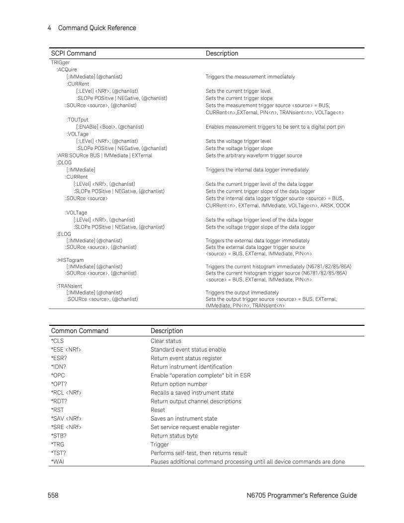
4 Command Quick Reference
558 N6705 Programmer’s Reference Guide
SCPI Command Description TRIGger :ACQuire [:IMMediate] (@chanlist) Triggers the measurement immediately :CURRent [:LEVel] <NRf>, (@chanlist) Sets the current trigger level :SLOPe POSitive | NEGative, (@chanlist) Sets the current trigger slope :SOURce <source>, (@chanlist) Sets the measurement trigger source <source> = BUS, CURRent<n>,EXTernal, PIN<n>, TRANsient<n>, VOLTage<n> :TOUTput [:ENABle] <Bool>, (@chanlist) Enables measurement triggers to be sent to a digital port pin :VOLTage [:LEVel] <NRf>, (@chanlist) Sets the voltage trigger level :SLOPe POSitive | NEGative, (@chanlist) Sets the voltage trigger slope :ARB:SOURce BUS | IMMediate | EXTernal Sets the arbitrary waveform trigger source :DLOG [:IMMediate] Triggers the internal data logger immediately :CURRent [:LEVel] <NRf>, (@chanlist) Sets the current trigger level of the data logger :SLOPe POSitive | NEGative, (@chanlist) Sets the current trigger slope of the data logger :SOURce <source> Sets the internal data logger trigger source <source> = BUS, CURRent<n>, EXTernal, IMMediate, VOLTage<n>, ARSK, OOOK :VOLTage [:LEVel] <NRf>, (@chanlist) Sets the voltage trigger level of the data logger :SLOPe POSitive | NEGative, (@chanlist) Sets the voltage trigger slope of the data logger :ELOG [:IMMediate] (@chanlist) Triggers the external data logger immediately :SOURce <source>, (@chanlist) Sets the external data logger trigger source <source> = BUS, EXTernal, IMMediate, PIN<n> :HISTogram [:IMMediate] (@chanlist) Triggers the current histogram immediately (N6781/82/85/86A) :SOURce <source>, (@chanlist) Sets the current histogram trigger source (N6781/82/85/86A) <source> = BUS, EXTernal, IMMediate, PIN<n> :TRANsient [:IMMediate] (@chanlist) Triggers the output immediately :SOURce <source>, (@chanlist) Sets the output trigger source <source> = BUS, EXTernal, IMMediate, PIN<n>, TRANsient<n>
Common Command Description
*CLS Clear status *ESE <NRf> Standard event status enable *ESR? Return event status register *IDN? Return instrument identification *OPC Enable "operation complete" bit in ESR *OPT? Return option number *RCL <NRf> Recalls a saved instrument state *RDT? Return output channel descriptions *RST Reset *SAV <NRf> Saves an instrument state *SRE <NRf> Set service request enable register *STB? Return status byte *TRG Trigger *TST? Performs self-test, then returns result *WAI Pauses additional command processing until all device commands are done
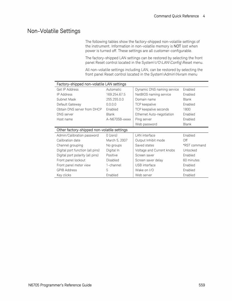
Command Quick Reference 4
N6705 Programmer’s Reference Guide 559
Non-Volatile Settings
The following tables show the factory-shipped non-volatile settings of the instrument. Information in non-volatile memory is NOT lost when power is turned off. These settings are all customer-configurable.
The factory-shipped LAN settings can be restored by selecting the front panel Reset control located in the System\I/O\LAN\Config\Reset menu.
All non-volatile settings including LAN, can be restored by selecting the front panel Reset control located in the System\Admin\Nvram menu
Factory-shipped non-volatile LAN settings Get IP Address Automatic Dynamic DNS naming service Enabled IP Address 169.254.67.5 NetBIOS naming service Enabled Subnet Mask 255.255.0.0 Domain name Blank Default Gateway 0.0.0.0 TCP keepalive Enabled Obtain DNS server from DHCP Enabled TCP keepalive seconds 1800 DNS server Blank Ethernet Auto-negotiation Enabled Host name A-N6705B-xxxxx Ping server Enabled
Web password Blank
Other factory-shipped non-volatile settings Admin/Calibration password 0 (zero) LAN interface Enabled Calibration date March 5, 2007 Output Inhibit mode Off Channel grouping No groups Saved states *RST command Digital port function (all pins) Digital In Voltage and Current knobs Unlocked Digital port polarity (all pins) Positive Screen saver Enabled Front panel lockout Disabled Screen saver delay 60 minutes Front panel meter view 1-channel USB interface Enabled GPIB Address 5 Wake on I/O Enabled Key clicks Enabled Web server Enabled
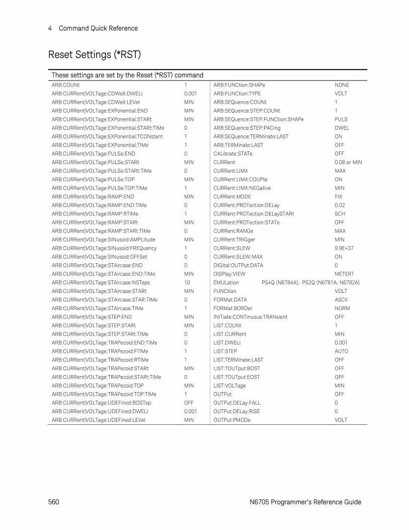
4 Command Quick Reference
560 N6705 Programmer’s Reference Guide
Reset Settings (*RST)
These settings are set by the Reset (*RST) command ARB:COUNt 1 ARB:FUNCtion:SHAPe NONE
ARB:CURRent|VOLTage:CDWell:DWELl 0.001 ARB:FUNCtion:TYPE VOLT
ARB:CURRent|VOLTage:CDWell:LEVel MIN ARB:SEQuence:COUNt 1
ARB:CURRent|VOLTage:EXPonential:END MIN ARB:SEQuence:STEP:COUNt 1
ARB:CURRent|VOLTage:EXPonential:STARt MIN ARB:SEQuence:STEP:FUNCtion:SHAPe PULS
ARB:CURRent|VOLTage:EXPonential:STARt:TIMe 0 ARB:SEQuence:STEP:PACing DWEL
ARB:CURRent|VOLTage:EXPonential:TCONstant 1 ARB:SEQuence:TERMinate:LAST ON
ARB:CURRent|VOLTage:EXPonential:TIMe 1 ARB:TERMinate:LAST OFF
ARB:CURRent|VOLTage:PULSe:END 0 CALibrate:STATe OFF
ARB:CURRent|VOLTage:PULSe:STARt MIN CURRent 0.08 or MIN
ARB:CURRent|VOLTage:PULSe:STARt:TIMe 0 CURRent:LIMit MAX
ARB:CURRent|VOLTage:PULSe:TOP MIN CURRent:LIMit:COUPle ON
ARB:CURRent|VOLTage:PULSe:TOP:TIMe 1 CURRent:LIMit:NEGative MIN
ARB:CURRent|VOLTage:RAMP:END MIN CURRent:MODE FIX
ARB:CURRent|VOLTage:RAMP:END:TIMe 0 CURRent:PROTection:DELay 0.02
ARB:CURRent|VOLTage:RAMP:RTIMe 1 CURRent:PROTection:DELaySTARt SCH
ARB:CURRent|VOLTage:RAMP:STARt MIN CURRent:PROTection:STATe OFF
ARB:CURRent|VOLTage:RAMP:STARt:TIMe 0 CURRent:RANGe MAX
ARB:CURRent|VOLTage:SINusoid:AMPLitude MIN CURRent:TRIGger MIN
ARB:CURRent|VOLTage:SINusoid:FREQuency 1 CURRent:SLEW 9.9E+37
ARB:CURRent|VOLTage:SINusoid:OFFSet 0 CURRent:SLEW:MAX ON
ARB:CURRent|VOLTage:STAircase:END 0 DIGital:OUTPut:DATA 0
ARB:CURRent|VOLTage:STAircase:END:TIMe MIN DISPlay:VIEW METER1
ARB:CURRent|VOLTage:STAircase:NSTeps 10 EMULation PS4Q (N6784A); PS2Q (N6781A, N6782A)
ARB:CURRent|VOLTage:STAircase:STARt MIN FUNCtion VOLT
ARB:CURRent|VOLTage:STAircase:STAR:TIMe 0 FORMat:DATA ASCII
ARB:CURRent|VOLTage:STAircase:TIMe 1 FORMat:BORDer NORM
ARB:CURRent|VOLTage:STEP:END MIN INITiate:CONTinuous:TRANsient OFF
ARB:CURRent|VOLTage:STEP:STARt MIN LIST:COUNt 1
ARB:CURRent|VOLTage:STEP:STARt:TIMe 0 LIST:CURRent MIN
ARB:CURRent|VOLTage:TRAPezoid:END:TIMe 0 LIST:DWELl 0.001
ARB:CURRent|VOLTage:TRAPezoid:FTIMe 1 LIST:STEP AUTO
ARB:CURRent|VOLTage:TRAPezoid:RTIMe 1 LIST:TERMinate:LAST OFF
ARB:CURRent|VOLTage:TRAPezoid:STARt MIN LIST:TOUTput:BOST OFF
ARB:CURRent|VOLTage:TRAPezoid:STARt:TIMe 0 LIST:TOUTput:EOST OFF
ARB:CURRent|VOLTage:TRAPezoid:TOP MIN LIST:VOLTage MIN
ARB:CURRent|VOLTage:TRAPezoid:TOP:TIMe 1 OUTPut OFF
ARB:CURRent|VOLTage:UDEFined:BOSTep OFF OUTPut:DELay:FALL 0
ARB:CURRent|VOLTage:UDEFined:DWELl 0.001 OUTPut:DELay:RISE 0
ARB:CURRent|VOLTage:UDEFined:LEVel MIN OUTPut:PMODe VOLT
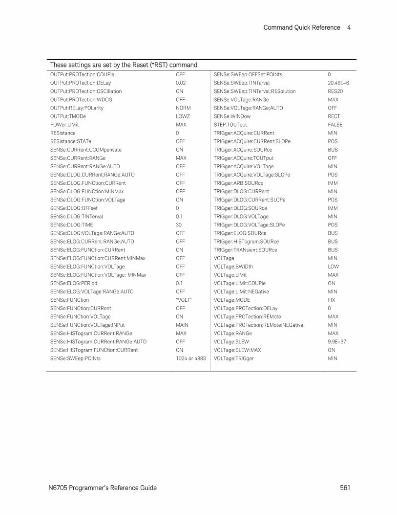
Command Quick Reference 4
N6705 Programmer’s Reference Guide 561
These settings are set by the Reset (*RST) command OUTPut:PROTection:COUPle OFF SENSe:SWEep:OFFSet:POINts 0
OUTPut:PROTection:DELay 0.02 SENSe:SWEep:TINTerval 20.48E6
OUTPut:PROTection:OSCillation ON SENSe:SWEep:TINTerval:RESolution RES20
OUTPut:PROTection:WDOG OFF SENSe:VOLTage:RANGe MAX
OUTPut:RELay:POLarity NORM SENSe:VOLTage:RANGe;AUTO OFF
OUTPut:TMODe LOWZ SENSe:WINDow RECT
POWer:LIMit MAX STEP:TOUTput FALSE
RESistance 0 TRIGger:ACQuire:CURRent MIN
RESistance:STATe OFF TRIGger:ACQuire:CURRent:SLOPe POS
SENSe:CURRent:CCOMpensate ON TRIGger:ACQuire:SOURce BUS
SENSe:CURRent:RANGe MAX TRIGger:ACQuire:TOUTput OFF
SENSe:CURRent:RANGe:AUTO OFF TRIGger:ACQuire:VOLTage MIN
SENSe:DLOG:CURRent:RANGe:AUTO OFF TRIGger:ACQuire:VOLTage:SLOPe POS
SENSe:DLOG:FUNCtion:CURRent OFF TRIGger:ARB:SOURce IMM
SENSe:DLOG:FUNCtion:MINMax OFF TRIGger:DLOG:CURRent MIN
SENSe:DLOG:FUNCtion:VOLTage ON TRIGger:DLOG:CURRent:SLOPe POS
SENSe:DLOG:OFFset 0 TRIGger:DLOG:SOURce IMM
SENSe:DLOG:TINTerval 0.1 TRIGger:DLOG:VOLTage MIN
SENSe:DLOG:TIME 30 TRIGger:DLOG:VOLTage:SLOPe POS
SENSe:DLOG:VOLTage:RANGe:AUTO OFF TRIGger:ELOG:SOURce BUS
SENSe:ELOG:CURRent:RANGe:AUTO OFF TRIGger:HISTogram:SOURce BUS
SENSe:ELOG:FUNCtion:CURRent ON TRIGger:TRANsient:SOURce BUS
SENSe:ELOG:FUNCtion:CURRent:MINMax OFF VOLTage MIN
SENSe:ELOG:FUNCtion:VOLTage OFF VOLTage:BWIDth LOW
SENSe:ELOG:FUNCtion:VOLTage: MINMax OFF VOLTage:LIMit MAX
SENSe:ELOG:PERiod 0.1 VOLTage:LIMit:COUPle ON
SENSe:ELOG:VOLTage:RANGe:AUTO OFF VOLTage:LIMit:NEGative MIN
SENSe:FUNCtion “VOLT” VOLTage:MODE FIX
SENSe:FUNCtion:CURRent OFF VOLTage:PROTection:DELay 0
SENSe:FUNCtion:VOLTage ON VOLTage:PROTection:REMote MAX
SENSe:FUNCtion:VOLTage:INPut MAIN VOLTage:PROTection:REMote:NEGative MIN
SENSe:HISTogram:CURRent:RANGe MAX VOLTage:RANGe MAX
SENSe:HISTogram:CURRent:RANGe:AUTO OFF VOLTage:SLEW 9.9E+37
SENSe:HISTogram:FUNCtion:CURRent ON VOLTage:SLEW:MAX ON
SENSe:SWEep:POINts 1024 or 4883 VOLTage:TRIGger MIN
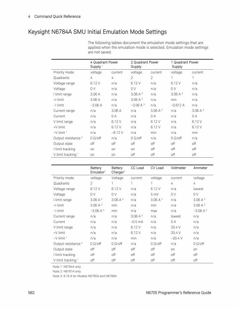
4 Command Quick Reference
562 N6705 Programmer’s Reference Guide
Keysight N6784A SMU Initial Emulation Mode Settings
The following tables document the emulation mode settings that are applied when the emulation mode is selected. Emulation mode settings are not saved.
4 Quadrant Power Supply 1
2 Quadrant Power Supply
1 Quadrant Power Supply
Priority mode voltage current voltage current voltage current
Quadrants 4 4 2 2 1 1
Voltage range 6.12 V n/a 6.12 V n/a 6.12 V n/a
Voltage 0 V n/a 0 V n/a 0 V n/a
I limit range 3.06 A n/a 3.06 A 3 n/a 3.06 A 3 n/a
+I limit 3.06 A n/a 3.06 A 3 n/a min n/a
−I limit −3.06 A n/a −3.06 A 3 n/a −0.612 A n/a
Current range n/a 3.06 A n/a 3.06 A 3 n/a 3.06 A 3
Current n/a 0 A n/a 0 A n/a 0 A
V limit range n/a 6.12 V n/a 6.12 V n/a 6.12 V
+V limit n/a 6.12 V n/a 6.12 V n/a 6.12 V
−V limit 1 n/a −6.12 V n/a min n/a min
Output resistance 2 0 Ω/off n/a 0 Ω/off n/a 0 Ω/off n/a
Output state off off off off off off
I limit tracking on on on off off off
V limit tracking 1 on on off off off off
Battery
Emulator2 Battery Charger2
CC Load CV Load Voltmeter Ammeter
Priority mode voltage Voltage current voltage current voltage
Quadrants 2 1 1 1 4 4
Voltage range 6.12 V 6.12 V n/a 6.12 V n/a lowest
Voltage 0 V 0 V n/a 5 mV 0 V 0 V
I limit range 3.06 A 3 3.06 A 3 n/a 3.06 A 3 n/a 3.06 A 3
+I limit 3.06 A 3 min n/a min n/a 3.06 A 3
−I limit −3.06 A 3 min n/a max n/a −3.06 A 3
Current range n/a n/a 3.06 A 3 n/a lowest n/a
Current n/a n/a -0.5 mA n/a 0 A n/a
V limit range n/a n/a 6.12 V n/a 20.4 V n/a
+V limit n/a n/a 6.12 V n/a 20.4 V n/a
−V limit 1 n/a n/a min n/a −20.4 V n/a
Output resistance 2 0 Ω/off 0 Ω/off n/a 0 Ω/off n/a 0 Ω/off
Output state off off off off on on
I limit tracking off off off off off off
V limit tracking 1 off off off off off off
Note 1: N6784A only
Note 2: N6781A only
Note 3: 8.16 A for Models N6785A and N6786A
N6705 Programmer’s Reference Guide 563
5 Programming Examples Arb Programming Example .......................................................... 564 Output Programming Example .................................................... 566 List Programming Example .......................................................... 568 Digitizer Programming Example .................................................. 570
This chapter contains several example programs to help you develop programs for your own application. The example programs are for illustration only, and are provided with the assumption that you are familiar with the programming language being demonstrated and the tools used to create and debug procedures. See chapter 3, “Commands by Subsyustem” for the SCPI command syntax.
You have a royalty-free right to use, modify, reproduce and distribute the example programs (and/or any modified version) in any way you find useful, provided you agree that Keysight Technologies has no warranty, obligations, or liability for any example programs.
The example programs are written in Microsoft Visual Basic 6.0 using the VISA COM IO library. The VISA COM library must be downloaded from the Automation-Ready CD-ROM to use these programs. For information about using VISA COM in another Visual Basic project, refer to “Programming Your Instruments” in the USB/LAN/GPIB Interfaces Connectivity Guide, also included on the Automation-Ready CD-ROM.
NOTE Example programs for the following programming environments are also included on the Product-Reference CD-ROM located at the back of this guide: Microsoft Visual Basic 6.0 Microsoft Visual C++ 6.0 Microsoft Excel Keysight VEE Pro The CD also contains IVI-COM and VXIplug&play drivers for your instrument.
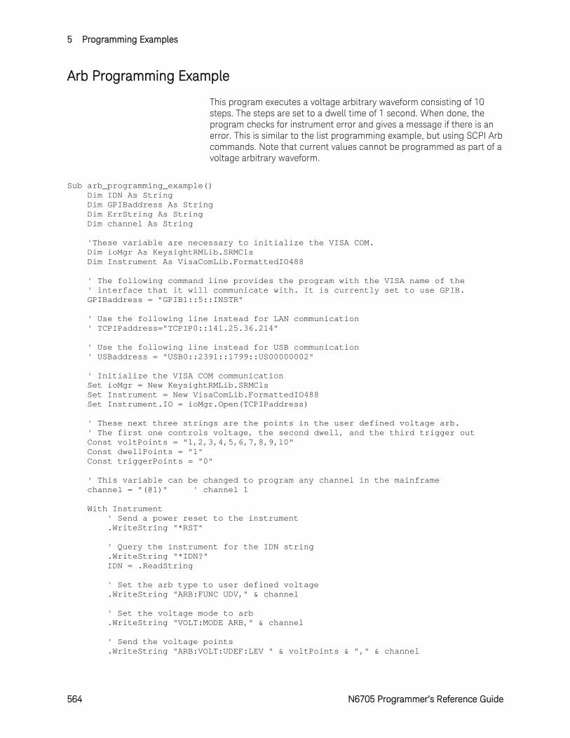
5 Programming Examples
564 N6705 Programmer’s Reference Guide
Arb Programming Example
This program executes a voltage arbitrary waveform consisting of 10 steps. The steps are set to a dwell time of 1 second. When done, the program checks for instrument error and gives a message if there is an error. This is similar to the list programming example, but using SCPI Arb commands. Note that current values cannot be programmed as part of a voltage arbitrary waveform.
Sub arb_programming_example() Dim IDN As String Dim GPIBaddress As String Dim ErrString As String Dim channel As String 'These variable are necessary to initialize the VISA COM. Dim ioMgr As KeysightRMLib.SRMCls Dim Instrument As VisaComLib.FormattedIO488 ' The following command line provides the program with the VISA name of the ' interface that it will communicate with. It is currently set to use GPIB. GPIBaddress = "GPIB1::5::INSTR" ' Use the following line instead for LAN communication ' TCPIPaddress="TCPIP0::141.25.36.214" ' Use the following line instead for USB communication ' USBaddress = "USB0::2391::1799::US00000002" ' Initialize the VISA COM communication Set ioMgr = New KeysightRMLib.SRMCls Set Instrument = New VisaComLib.FormattedIO488 Set Instrument.IO = ioMgr.Open(TCPIPaddress) ' These next three strings are the points in the user defined voltage arb. ' The first one controls voltage, the second dwell, and the third trigger out Const voltPoints = "1,2,3,4,5,6,7,8,9,10" Const dwellPoints = "1" Const triggerPoints = "0" ' This variable can be changed to program any channel in the mainframe channel = "(@1)" ' channel 1 With Instrument ' Send a power reset to the instrument .WriteString "*RST" ' Query the instrument for the IDN string .WriteString "*IDN?" IDN = .ReadString ' Set the arb type to user defined voltage .WriteString "ARB:FUNC UDV," & channel ' Set the voltage mode to arb .WriteString "VOLT:MODE ARB," & channel ' Send the voltage points .WriteString "ARB:VOLT:UDEF:LEV " & voltPoints & "," & channel
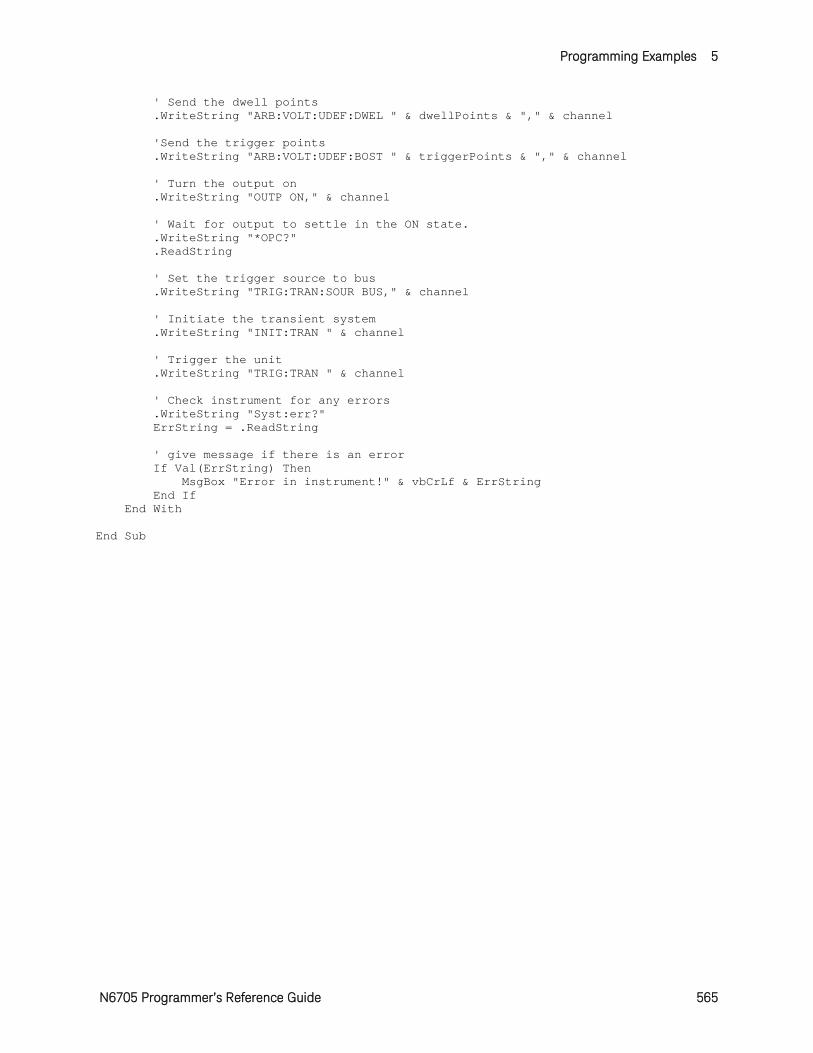
Programming Examples 5
N6705 Programmer’s Reference Guide 565
' Send the dwell points .WriteString "ARB:VOLT:UDEF:DWEL " & dwellPoints & "," & channel 'Send the trigger points .WriteString "ARB:VOLT:UDEF:BOST " & triggerPoints & "," & channel ' Turn the output on .WriteString "OUTP ON," & channel ' Wait for output to settle in the ON state. .WriteString "*OPC?" .ReadString ' Set the trigger source to bus .WriteString "TRIG:TRAN:SOUR BUS," & channel ' Initiate the transient system .WriteString "INIT:TRAN " & channel ' Trigger the unit .WriteString "TRIG:TRAN " & channel ' Check instrument for any errors .WriteString "Syst:err?" ErrString = .ReadString ' give message if there is an error If Val(ErrString) Then MsgBox "Error in instrument!" & vbCrLf & ErrString End If End With End Sub
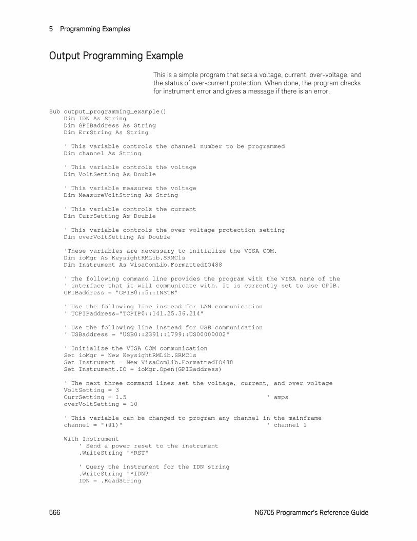
5 Programming Examples
566 N6705 Programmer’s Reference Guide
Output Programming Example
This is a simple program that sets a voltage, current, over-voltage, and the status of over-current protection. When done, the program checks for instrument error and gives a message if there is an error.
Sub output_programming_example() Dim IDN As String Dim GPIBaddress As String Dim ErrString As String ' This variable controls the channel number to be programmed Dim channel As String ' This variable controls the voltage Dim VoltSetting As Double ' This variable measures the voltage Dim MeasureVoltString As String ' This variable controls the current Dim CurrSetting As Double ' This variable controls the over voltage protection setting Dim overVoltSetting As Double 'These variables are necessary to initialize the VISA COM. Dim ioMgr As KeysightRMLib.SRMCls Dim Instrument As VisaComLib.FormattedIO488 ' The following command line provides the program with the VISA name of the ' interface that it will communicate with. It is currently set to use GPIB. GPIBaddress = "GPIB0::5::INSTR" ' Use the following line instead for LAN communication ' TCPIPaddress="TCPIP0::141.25.36.214" ' Use the following line instead for USB communication ' USBaddress = "USB0::2391::1799::US00000002" ' Initialize the VISA COM communication Set ioMgr = New KeysightRMLib.SRMCls Set Instrument = New VisaComLib.FormattedIO488 Set Instrument.IO = ioMgr.Open(GPIBaddress) ' The next three command lines set the voltage, current, and over voltage VoltSetting = 3 CurrSetting = 1.5 ' amps overVoltSetting = 10 ' This variable can be changed to program any channel in the mainframe channel = "(@1)" ' channel 1 With Instrument ' Send a power reset to the instrument .WriteString "*RST" ' Query the instrument for the IDN string .WriteString "*IDN?" IDN = .ReadString
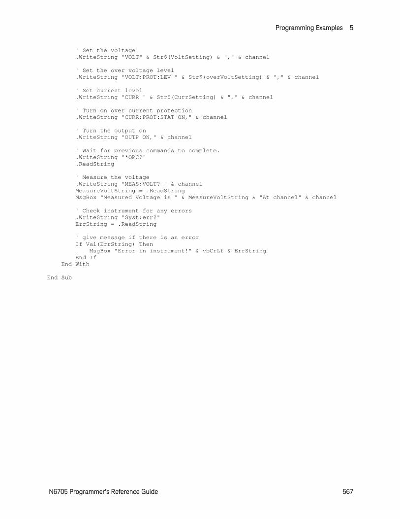
Programming Examples 5
N6705 Programmer’s Reference Guide 567
' Set the voltage .WriteString "VOLT" & Str$(VoltSetting) & "," & channel ' Set the over voltage level .WriteString "VOLT:PROT:LEV " & Str$(overVoltSetting) & "," & channel ' Set current level .WriteString "CURR " & Str$(CurrSetting) & "," & channel ' Turn on over current protection .WriteString "CURR:PROT:STAT ON," & channel ' Turn the output on .WriteString "OUTP ON," & channel ' Wait for previous commands to complete. .WriteString "*OPC?" .ReadString ' Measure the voltage .WriteString "MEAS:VOLT? " & channel MeasureVoltString = .ReadString MsgBox "Measured Voltage is " & MeasureVoltString & "At channel" & channel ' Check instrument for any errors .WriteString "Syst:err?" ErrString = .ReadString ' give message if there is an error If Val(ErrString) Then MsgBox "Error in instrument!" & vbCrLf & ErrString End If End With End Sub
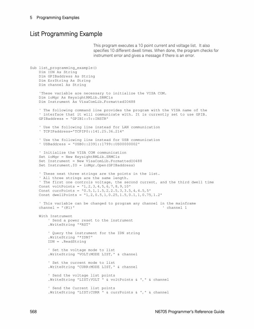
5 Programming Examples
568 N6705 Programmer’s Reference Guide
List Programming Example
This program executes a 10 point current and voltage list. It also specifies 10 different dwell times. When done, the program checks for instrument error and gives a message if there is an error.
Sub list_programming_example() Dim IDN As String Dim GPIBaddress As String Dim ErrString As String Dim channel As String 'These variable are necessary to initialize the VISA COM. Dim ioMgr As KeysightRMLib.SRMCls Dim Instrument As VisaComLib.FormattedIO488 ' The following command line provides the program with the VISA name of the ' interface that it will communicate with. It is currently set to use GPIB. GPIBaddress = "GPIB1::5::INSTR" ' Use the following line instead for LAN communication ' TCPIPaddress="TCPIP0::141.25.36.214" ' Use the following line instead for USB communication ' USBaddress = "USB0::2391::1799::US00000002" ' Initialize the VISA COM communication Set ioMgr = New KeysightRMLib.SRMCls Set Instrument = New VisaComLib.FormattedIO488 Set Instrument.IO = ioMgr.Open(GPIBaddress) ' These next three strings are the points in the list. ' All three strings are the same length. ' The first one controls voltage, the second current, and the third dwell time Const voltPoints = "1,2,3,4,5,6,7,8,9,10" Const currPoints = "0.5,1,1.5,2,2.5,3,3.5,4,4.5,5" Const dwellPoints = "1,2,0.5,1,0.25,1.5,0.1,1,0.75,1.2" ' This variable can be changed to program any channel in the mainframe channel = "(@1)" ' channel 1 With Instrument ' Send a power reset to the instrument .WriteString "*RST" ' Query the instrument for the IDN string .WriteString "*IDN?" IDN = .ReadString ' Set the voltage mode to list .WriteString "VOLT:MODE LIST," & channel ' Set the current mode to list .WriteString "CURR:MODE LIST," & channel ' Send the voltage list points .WriteString "LIST:VOLT " & voltPoints & "," & channel ' Send the Current list points .WriteString "LIST:CURR " & currPoints & "," & channel
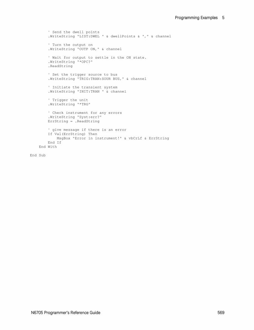
Programming Examples 5
N6705 Programmer’s Reference Guide 569
' Send the dwell points .WriteString "LIST:DWEL " & dwellPoints & "," & channel ' Turn the output on .WriteString "OUTP ON," & channel ' Wait for output to settle in the ON state. .WriteString "*OPC?" .ReadString ' Set the trigger source to bus .WriteString "TRIG:TRAN:SOUR BUS," & channel ' Initiate the transient system .WriteString "INIT:TRAN " & channel ' Trigger the unit .WriteString "*TRG" ' Check instrument for any errors .WriteString "Syst:err?" ErrString = .ReadString ' give message if there is an error If Val(ErrString) Then MsgBox "Error in instrument!" & vbCrLf & ErrString End If End With End Sub
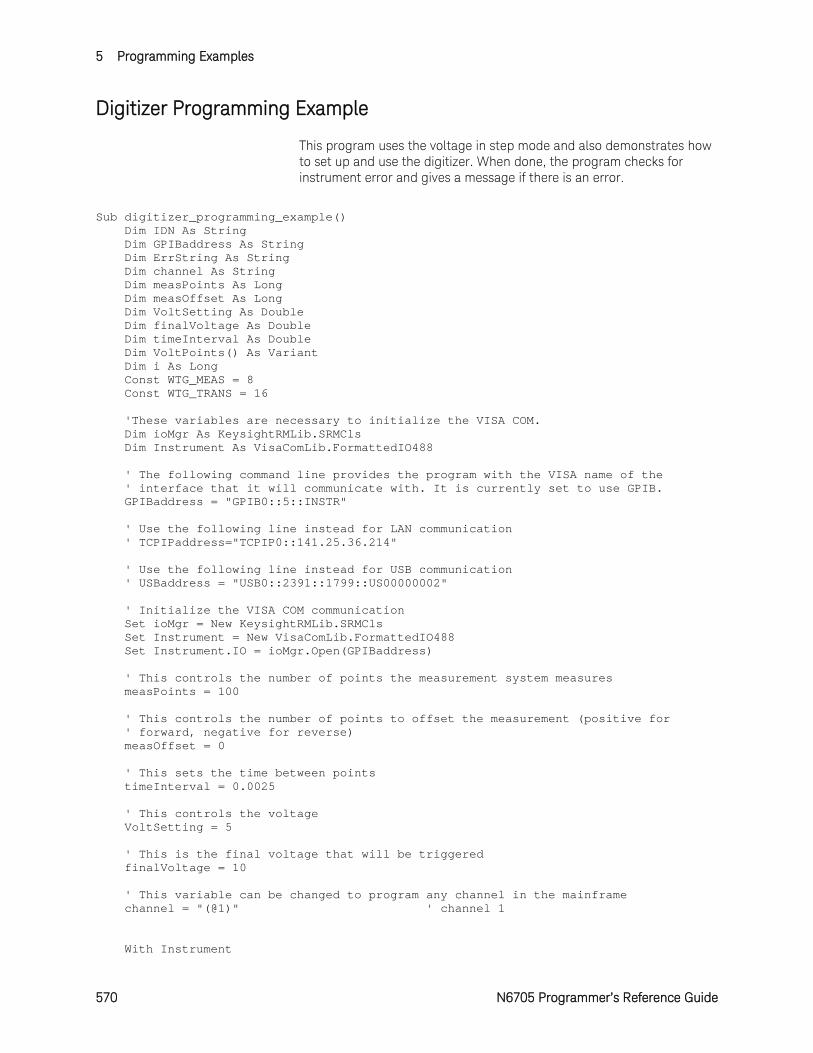
5 Programming Examples
570 N6705 Programmer’s Reference Guide
Digitizer Programming Example
This program uses the voltage in step mode and also demonstrates how to set up and use the digitizer. When done, the program checks for instrument error and gives a message if there is an error.
Sub digitizer_programming_example() Dim IDN As String Dim GPIBaddress As String Dim ErrString As String Dim channel As String Dim measPoints As Long Dim measOffset As Long Dim VoltSetting As Double Dim finalVoltage As Double Dim timeInterval As Double Dim VoltPoints() As Variant Dim i As Long Const WTG_MEAS = 8 Const WTG_TRANS = 16 'These variables are necessary to initialize the VISA COM. Dim ioMgr As KeysightRMLib.SRMCls Dim Instrument As VisaComLib.FormattedIO488 ' The following command line provides the program with the VISA name of the ' interface that it will communicate with. It is currently set to use GPIB. GPIBaddress = "GPIB0::5::INSTR" ' Use the following line instead for LAN communication ' TCPIPaddress="TCPIP0::141.25.36.214" ' Use the following line instead for USB communication ' USBaddress = "USB0::2391::1799::US00000002" ' Initialize the VISA COM communication Set ioMgr = New KeysightRMLib.SRMCls Set Instrument = New VisaComLib.FormattedIO488 Set Instrument.IO = ioMgr.Open(GPIBaddress) ' This controls the number of points the measurement system measures measPoints = 100 ' This controls the number of points to offset the measurement (positive for ' forward, negative for reverse) measOffset = 0 ' This sets the time between points timeInterval = 0.0025 ' This controls the voltage VoltSetting = 5 ' This is the final voltage that will be triggered finalVoltage = 10 ' This variable can be changed to program any channel in the mainframe channel = "(@1)" ' channel 1 With Instrument
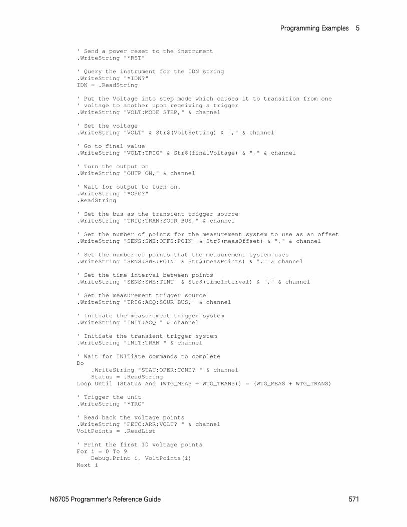
Programming Examples 5
N6705 Programmer’s Reference Guide 571
' Send a power reset to the instrument .WriteString "*RST" ' Query the instrument for the IDN string .WriteString "*IDN?" IDN = .ReadString ' Put the Voltage into step mode which causes it to transition from one ' voltage to another upon receiving a trigger .WriteString "VOLT:MODE STEP," & channel ' Set the voltage .WriteString "VOLT" & Str$(VoltSetting) & "," & channel ' Go to final value .WriteString "VOLT:TRIG" & Str$(finalVoltage) & "," & channel ' Turn the output on .WriteString "OUTP ON," & channel ' Wait for output to turn on. .WriteString "*OPC?" .ReadString ' Set the bus as the transient trigger source .WriteString "TRIG:TRAN:SOUR BUS," & channel ' Set the number of points for the measurement system to use as an offset .WriteString "SENS:SWE:OFFS:POIN" & Str$(measOffset) & "," & channel ' Set the number of points that the measurement system uses .WriteString "SENS:SWE:POIN" & Str$(measPoints) & "," & channel ' Set the time interval between points .WriteString "SENS:SWE:TINT" & Str$(timeInterval) & "," & channel ' Set the measurement trigger source .WriteString "TRIG:ACQ:SOUR BUS," & channel ' Initiate the measurement trigger system .WriteString "INIT:ACQ " & channel ' Initiate the transient trigger system .WriteString "INIT:TRAN " & channel ' Wait for INITiate commands to complete Do .WriteString "STAT:OPER:COND? " & channel Status = .ReadString Loop Until (Status And (WTG_MEAS + WTG_TRANS)) = (WTG_MEAS + WTG_TRANS) ' Trigger the unit .WriteString "*TRG" ' Read back the voltage points .WriteString "FETC:ARR:VOLT? " & channel VoltPoints = .ReadList ' Print the first 10 voltage points For i = 0 To 9 Debug.Print i, VoltPoints(i) Next i
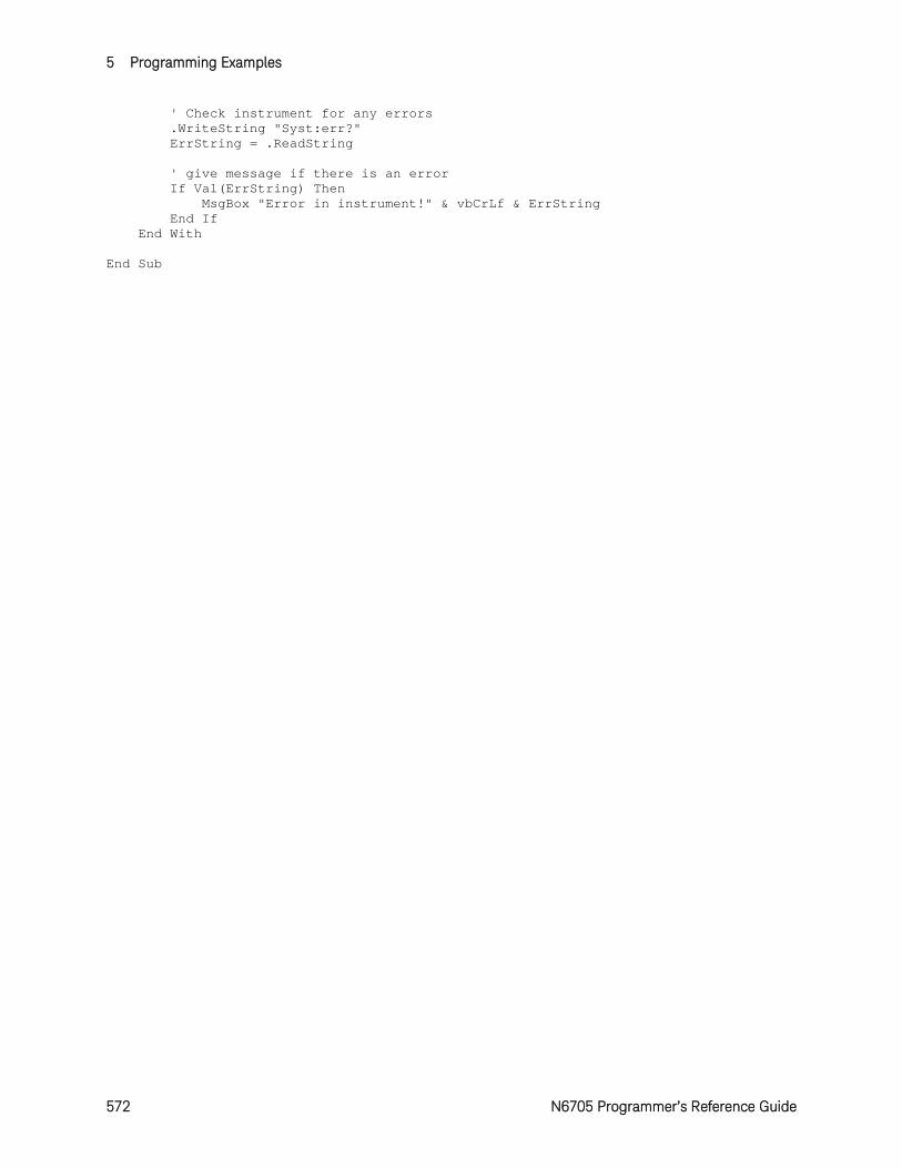
5 Programming Examples
572 N6705 Programmer’s Reference Guide
' Check instrument for any errors .WriteString "Syst:err?" ErrString = .ReadString ' give message if there is an error If Val(ErrString) Then MsgBox "Error in instrument!" & vbCrLf & ErrString End If End With End Sub
N6705 Programmer’s Reference Guide 573
6 SCPI Error Messages Introduction .................................................................................. 574 Error List ....................................................................................... 574
This appendix gives the error numbers and descriptions that are returned by the Keysight N6705.
6 SCPI Error Messages
574 N6705 Programmer’s Reference Guide
Intoduction
The front-panel ERR annunciator turns on when one or more errors are currently stored in the error queue.
Errors are retrieved in first-in-first-out (FIFO) order. The first error returned is the first error that was stored.
Errors are cleared as you read them. When you have read all errors from the error queue, the ERR annunciator turns off and the errors are cleared.
If more errors have occurred than can fit in the buffer, the last error stored in the queue (the most recent error) is replaced with -350,"Error queue overflow". No additional errors are stored until you remove errors from the queue. If no errors have occurred when you read the error queue, the instrument responds with +0,"No error".
The error queue is cleared by the *CLS (Clear Status) command and when power is cycled. The errors are also cleared when you read the error queue. The error queue is not cleared by a Factory Reset (*RST command) or an Instrument Preset (SYSTem:PRESet command).
Front-Panel Operation:
If the ERR annunciator is on, press the Error key to view the errors. Use the navigation keys to scroll through the error list. All errors are cleared when you exit the menu.
Remote Interface Operation:
SYSTem:ERRor? Reads and clears one error from the queue Errors have the following format (the error string may contain up to 80 characters): -113,"Undefined header"
Error List
Error Device-dependent Errors (these errors set Standard Event Status register bit #3)
0 No error This is the response to the ERR? query when there are no errors.
100 Too many channels You have specified more channels than are installed in the mainframe.
101 Calibration state is off Calibration is not enabled. The instrument will not accept calibration commands.
102 Calibration password is incorrect The calibration password is incorrect.
103 Calibration is inhibited by switch setting Calibration mode is locked out by the calibration switch.
104 Bad sequence of calibration commands Calibration commands have not been entered in the proper sequence.
105 Unexpected output current The measured output current is outside the acceptable range.
SCPI Error Messages 6
N6705 Programmer’s Reference Guide 575
Device-dependent Errors (continued)
106 Zero measurement out of range error The “zero” measurement value is outside the acceptable range.
107 Programming cal constants out of range The programmed calibration constant is outside the acceptable range.
108 Measurement cal constants out of range The measurement calibration constant is outside the acceptable range.
109 Over voltage cal constants out of range The over voltage calibration constant is outside the acceptable range.
110 Wrong V+I The instrument was unable to set the correct voltage or current value.
111 Aux vloc cal constants out of range Calibration constants on the internal auxiliary local ADC are outside the acceptable range.
112 Aux vrem cal constants out of range Calibration constants on the internal auxiliary remote ADC are outside the acceptable range.
113 Aux imon cal constants out of range Calibration constants on the internal auxiliary imon ADC are outside the acceptable range.
114 Wrong status An incorrect status function has been reported.
115 Output track resistance out of range The output track resistance is out of range. Re-calibrate the output module.
116 Locked out by internal switch setting This function has been locked out by an internal switch in the mainframe.
117 Calibration error A calibration error has occurred. Do not save calibration constants. Try re-calibrating the unit.
200 Hardware error channel <channel> A hardware error has occurred on the specified channel.
201 Invalid configuration, empty slots There is an empty slot between modules. This configuration is not allowed.
202 Selftest Fail A selftest failure has occurred. See selftest failure list for details.
203 Compatibility function not implemented The requested compatibility function is not available.
204 NVRAM checksum error A checksum error has occurred in the instrument’s nonvolatile random access memory.
205 NVRAM full The nonvolatile random access memory of the instrument is full.
206 File not found The internal calibration file or the internal channel attribute file was not found in NVRAM.
207 Cal file version error The calibration file was written or read using old firmware. Firmware must be updated.
208 Running backup firmware The instrument is presently running the backup (previous) version of the firmware.
209 Modules do not match group NV config One or more modules that have their output coupled do not match the instrument state settings.
210 Frame NVRAM error A non-volatile RAM error has occurred in the mainframe
211 Output state couple modules do not match One or more modules in the group does not match the non-volatile configurations settings.
302 Option not installed The option that is programmed by this command is not installed.
6 SCPI Error Messages
576 N6705 Programmer’s Reference Guide
Device-dependent Errors (continued) 303 There is not a valid acquisition to fetch from
There is no valid data in the measurement buffer.
304 Volt and curr in incompatible transient modes Voltage and current cannot be in Step and List mode at the same time.
305 A triggered value is on a different range A triggered value is on a different range than the one that is presently set.
306 Too many list points Too many list points have been specified.
307 List lengths are not equivalent One or more lists are not the same length.
308 This setting cannot be changed while transient trigger is initiated Setting cannot be changed while the instrument is waiting for or executing a trigger sequence.
309 Cannot initiate, voltage and current in fixed mode Cannot initiate transient generator. Either the voltage or current function is set to Fixed mode.
310 The command is not supported by this model This power modules either does not have the hardware capability or the options required to support this command.
311 This group of channel has non-identical features One or more modules in this group does not match the ratings or options of the other modules.
312 The command is disabled when the channel is grouped This command is disabled when the output channel is grouped.
313 Datalog time interval is out of range The data log time interval is outside the programmable range.
314 Time of day clock has stopped The time of day clock has stopped. Replace the internal battery. See Service Guide.
315 Settings conflict error A data element could not be programmed because of the present instrument state.
316 Mass storage error The mass storage memory has been exceeded.
317 Invalid format An invalid data format was found in the command string.
318 Datalog error An error has occurred in the data returned by the datalogger.
319 Measurement is not allowed while datalogger is running You cannot make measurements in Meter View or Scope View while the datalogger is running.
320 Firmware update error This may be due to the instrument hardware not being able to support the firmware version.
321 Modules do not match data format One or more power modules does not match the data format of the file that is being loaded.
Command Errors (these errors set Standard Event Status register bit #5) −100 Command error
Generic syntax error.
−101 Invalid character An invalid character was found in the command string.
−102 Syntax error Invalid syntax was found in the command string. Check for blank spaces.
−103 Invalid separator An invalid separator was found in the command string. Check for proper use of , ; :
−104 Data type error A different data type than the one allowed was found in the command string.
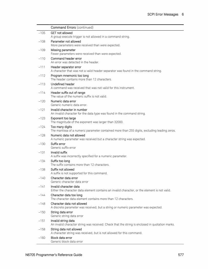
SCPI Error Messages 6
N6705 Programmer’s Reference Guide 577
Command Errors (continued)
−105 GET not allowed A group execute trigger is not allowed in a command string.
−108 Parameter not allowed More parameters were received than were expected.
−109 Missing parameter Fewer parameters were received than were expected.
−110 Command header error An error was detected in the header.
−111 Header separator error A character that was not a valid header separator was found in the command string.
−112 Program mnemonic too long The header contains more than 12 characters.
−113 Undefined header A command was received that was not valid for this instrument.
−114 Header suffix out of range The value of the numeric suffix is not valid.
−120 Numeric data error Generic numeric data error.
−121 Invalid character in number An invalid character for the data type was found in the command string.
−123 Exponent too large The magnitude of the exponent was larger than 32000.
−124 Too many digits The mantissa of a numeric parameter contained more than 255 digits, excluding leading zeros.
−128 Numeric data not allowed A numeric parameter was received but a character string was expected.
−130 Suffix error Generic suffix error
−131 Invalid suffix A suffix was incorrectly specified for a numeric parameter.
−134 Suffix too long The suffix contains more than 12 characters.
−138 Suffix not allowed A suffix is not supported for this command.
−140 Character data error Generic character data error
−141 Invalid character data Either the character data element contains an invalid character, or the element is not valid.
−144 Character data too long The character data element contains more than 12 characters.
−148 Character data not allowed A discrete parameter was received, but a string or numeric parameter was expected.
−150 String data error Generic string data error
−151 Invalid string data An invalid character string was received. Check that the string is enclosed in quotation marks.
−158 String data not allowed A character string was received, but is not allowed for this command.
−160 Block data error Generic block data error
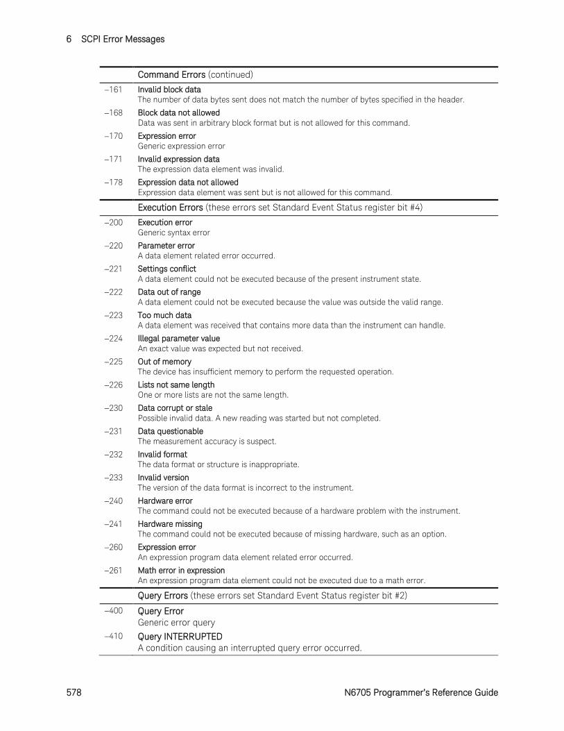
6 SCPI Error Messages
578 N6705 Programmer’s Reference Guide
Command Errors (continued)
−161 Invalid block data The number of data bytes sent does not match the number of bytes specified in the header.
−168 Block data not allowed Data was sent in arbitrary block format but is not allowed for this command.
−170 Expression error Generic expression error
−171 Invalid expression data The expression data element was invalid.
−178 Expression data not allowed Expression data element was sent but is not allowed for this command.
Execution Errors (these errors set Standard Event Status register bit #4)
−200 Execution error Generic syntax error
−220 Parameter error A data element related error occurred.
−221 Settings conflict A data element could not be executed because of the present instrument state.
−222 Data out of range A data element could not be executed because the value was outside the valid range.
−223 Too much data A data element was received that contains more data than the instrument can handle.
−224 Illegal parameter value An exact value was expected but not received.
−225 Out of memory The device has insufficient memory to perform the requested operation.
−226 Lists not same length One or more lists are not the same length.
−230 Data corrupt or stale Possible invalid data. A new reading was started but not completed.
−231 Data questionable The measurement accuracy is suspect.
−232 Invalid format The data format or structure is inappropriate.
−233 Invalid version The version of the data format is incorrect to the instrument.
−240 Hardware error The command could not be executed because of a hardware problem with the instrument.
−241 Hardware missing The command could not be executed because of missing hardware, such as an option.
−260 Expression error An expression program data element related error occurred.
−261 Math error in expression An expression program data element could not be executed due to a math error.
Query Errors (these errors set Standard Event Status register bit #2)
−400 Query Error Generic error query
−410 Query INTERRUPTED A condition causing an interrupted query error occurred.
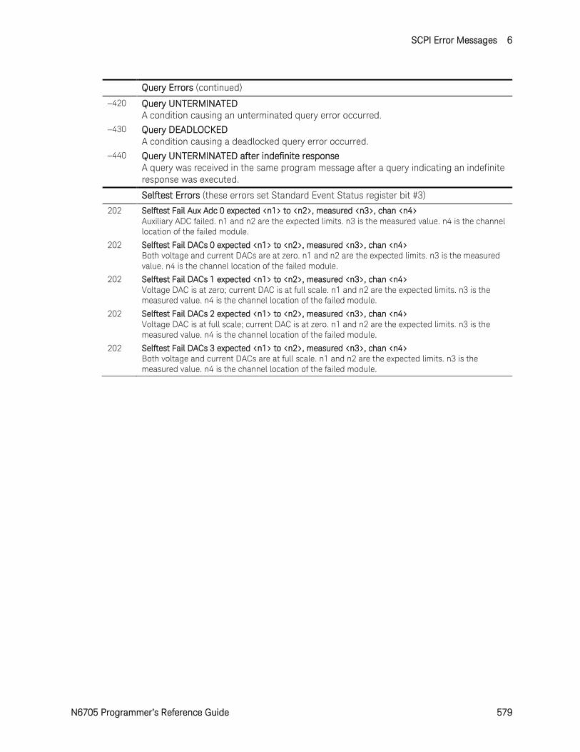
SCPI Error Messages 6
N6705 Programmer’s Reference Guide 579
Query Errors (continued)
−420 Query UNTERMINATED A condition causing an unterminated query error occurred.
−430 Query DEADLOCKED A condition causing a deadlocked query error occurred.
−440 Query UNTERMINATED after indefinite response A query was received in the same program message after a query indicating an indefinite response was executed.
Selftest Errors (these errors set Standard Event Status register bit #3)
202 Selftest Fail Aux Adc 0 expected <n1> to <n2>, measured <n3>, chan <n4> Auxiliary ADC failed. n1 and n2 are the expected limits. n3 is the measured value. n4 is the channel location of the failed module.
202 Selftest Fail DACs 0 expected <n1> to <n2>, measured <n3>, chan <n4> Both voltage and current DACs are at zero. n1 and n2 are the expected limits. n3 is the measured value. n4 is the channel location of the failed module.
202 Selftest Fail DACs 1 expected <n1> to <n2>, measured <n3>, chan <n4> Voltage DAC is at zero; current DAC is at full scale. n1 and n2 are the expected limits. n3 is the measured value. n4 is the channel location of the failed module.
202 Selftest Fail DACs 2 expected <n1> to <n2>, measured <n3>, chan <n4> Voltage DAC is at full scale; current DAC is at zero. n1 and n2 are the expected limits. n3 is the measured value. n4 is the channel location of the failed module.
202 Selftest Fail DACs 3 expected <n1> to <n2>, measured <n3>, chan <n4> Both voltage and current DACs are at full scale. n1 and n2 are the expected limits. n3 is the measured value. n4 is the channel location of the failed module.

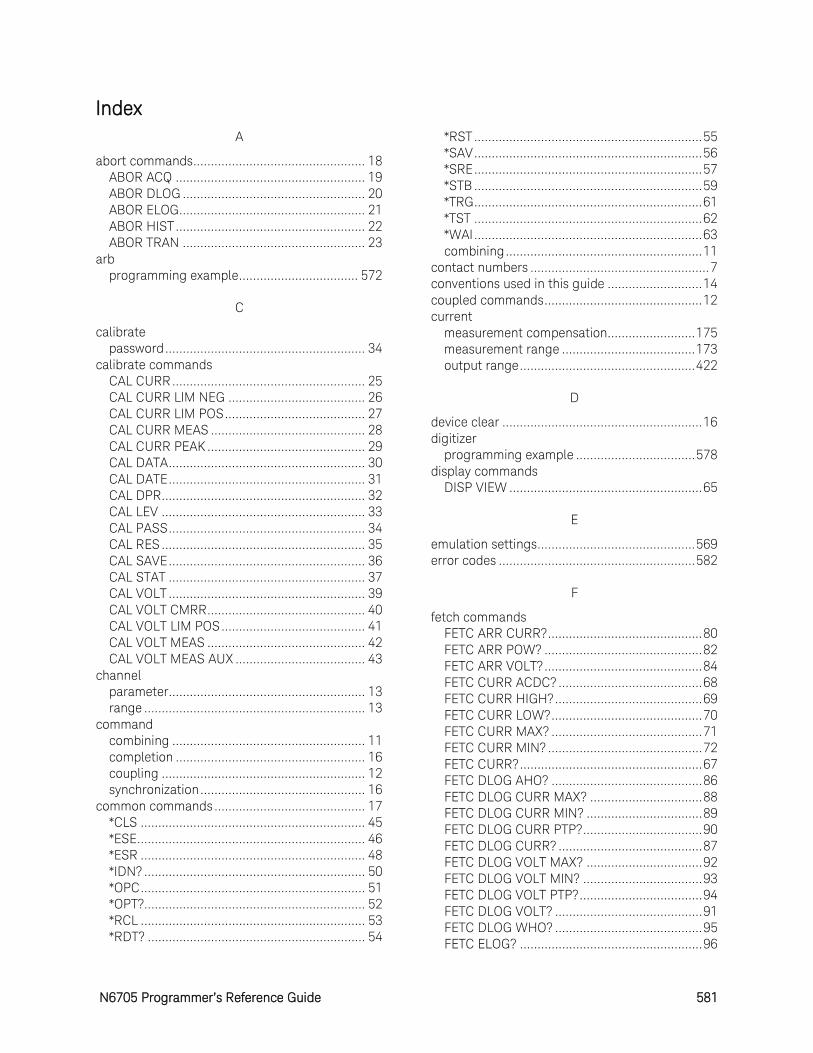
N6705 Programmer’s Reference Guide 581
Index A
abort commands ................................................. 18 ABOR ACQ ...................................................... 19 ABOR DLOG .................................................... 20 ABOR ELOG ..................................................... 21 ABOR HIST ...................................................... 22 ABOR TRAN .................................................... 23
arb programming example .................................. 572
C
calibrate password ......................................................... 34
calibrate commands CAL CURR ....................................................... 25 CAL CURR LIM NEG ....................................... 26 CAL CURR LIM POS ........................................ 27 CAL CURR MEAS ............................................ 28 CAL CURR PEAK ............................................. 29 CAL DATA ........................................................ 30 CAL DATE ........................................................ 31 CAL DPR .......................................................... 32 CAL LEV .......................................................... 33 CAL PASS ........................................................ 34 CAL RES .......................................................... 35 CAL SAVE ........................................................ 36 CAL STAT ........................................................ 37 CAL VOLT ........................................................ 39 CAL VOLT CMRR ............................................. 40 CAL VOLT LIM POS ......................................... 41 CAL VOLT MEAS ............................................. 42 CAL VOLT MEAS AUX ..................................... 43
channel parameter ........................................................ 13 range ............................................................... 13
command combining ....................................................... 11 completion ...................................................... 16 coupling .......................................................... 12 synchronization ............................................... 16
common commands ........................................... 17 *CLS ................................................................ 45 *ESE ................................................................. 46 *ESR ................................................................ 48 *IDN? ............................................................... 50 *OPC ................................................................ 51 *OPT? ............................................................... 52 *RCL ................................................................ 53 *RDT? .............................................................. 54
*RST ................................................................. 55 *SAV ................................................................. 56 *SRE ................................................................. 57 *STB ................................................................. 59 *TRG ................................................................. 61 *TST ................................................................. 62 *WAI ................................................................. 63 combining ........................................................ 11
contact numbers ................................................... 7 conventions used in this guide ........................... 14 coupled commands ............................................. 12 current
measurement compensation......................... 175 measurement range ...................................... 173 output range .................................................. 422
D
device clear ......................................................... 16 digitizer
programming example .................................. 578 display commands
DISP VIEW ....................................................... 65
E
emulation settings ............................................. 569 error codes ........................................................ 582
F
fetch commands FETC ARR CURR? ............................................ 80 FETC ARR POW? ............................................. 82 FETC ARR VOLT? ............................................. 84 FETC CURR ACDC? ......................................... 68 FETC CURR HIGH? .......................................... 69 FETC CURR LOW? ........................................... 70 FETC CURR MAX? ........................................... 71 FETC CURR MIN? ............................................ 72 FETC CURR? .................................................... 67 FETC DLOG AHO? ........................................... 86 FETC DLOG CURR MAX? ................................ 88 FETC DLOG CURR MIN? ................................. 89 FETC DLOG CURR PTP? .................................. 90 FETC DLOG CURR? ......................................... 87 FETC DLOG VOLT MAX? ................................. 92 FETC DLOG VOLT MIN? .................................. 93 FETC DLOG VOLT PTP? ................................... 94 FETC DLOG VOLT? .......................................... 91 FETC DLOG WHO? .......................................... 95 FETC ELOG? .................................................... 96
Index
582 N6705 Programmer’s Reference Guide
FETC HIST CURR? .......................................... 98 FETC POW? ..................................................... 73 FETC VOLT ACDC? .......................................... 75 FETC VOLT HIGH? .......................................... 76 FETC VOLT LOW? ........................................... 77 FETC VOLT MAX? ............................................ 78 FETC VOLT MIN? ............................................. 79 FETC VOLT? .................................................... 74
format commands FORM [DATA] ................................................ 100 FORM BORD ................................................. 101
H
hcopy commands HCOP SDUM DATA? ..................................... 103
headers ............................................................... 13 history ................................................................... 2
I
initiate commands INIT ACQ........................................................ 105 INIT CONT TRAN ........................................... 110 INIT DLOG ..................................................... 106 INIT ELOG ...................................................... 107 INIT HIST ....................................................... 108 INIT TRAN ...................................................... 109
instrument drivers ................................................. 6
L
list programming example .................................. 576
M
MAV................................................................... 487 measure commands
MEAS ARR CURR? ........................................ 129 MEAS ARR POW? ......................................... 131 MEAS ARR VOLT? ......................................... 133 MEAS CURR ACDC? ..................................... 113 MEAS CURR HIGH? ...................................... 114 MEAS CURR LOW? ....................................... 116 MEAS CURR MAX? ....................................... 118 MEAS CURR MIN? ........................................ 119 MEAS CURR? ................................................ 112 MEAS POW? .................................................. 120 MEAS VOLT ACDC? ...................................... 122 MEAS VOLT HIGH? ....................................... 123 MEAS VOLT LOW? ........................................ 125 MEAS VOLT MAX? ........................................ 127 MEAS VOLT MIN? ......................................... 128
MEAS VOLT? .................................................. 121 message separator .............................................. 14 message terminator
end or identify .................................................. 14 newline ............................................................ 14
mmemory commands MMEM ATTR? ................................................ 136 MMEM DATA? ................................................ 138 MMEM DEL .................................................... 139 MMEM EXP DLOG ......................................... 140 MMEM LOAD ARB SEQ ................................. 141 MMEM STOR ARB SEQ ................................. 142
MSS ................................................................... 487 multipliers ............................................................ 15
N
non-volatile RAM settings................................. 566 numeric data formats .......................................... 15
O
operation status group ...................................... 487 header ................................................................. 11 output
programming example .................................. 574 queue ............................................................. 487
output commands OUTP .............................................................. 144 OUTP CHAN .................................................. 146 OUTP COUP DOFF......................................... 148 OUTP COUP DOFF MODE ............................. 149 OUTP COUP MAX DOFF? .............................. 151 OUTP DEL FALL ............................................. 152 OUTP DEL RISE ............................................. 154 OUTP INH MODE ........................................... 159 OUTP PMOD .................................................. 156 OUTP PON STAT ............................................ 161 OUTP PROT CLE ............................................ 162 OUTP PROT COUP ......................................... 163 OUTP PROT DEL ............................................ 164 OUTP PROT OSC ........................................... 166 OUTP PROT WDOG ....................................... 167 OUTP PROT WDOG DEL ............................... 168 OUTP REL POL .............................................. 169 OUTP TMOD .................................................. 158
P
print date ............................................................... 2
Q
query
Index
N6705 Programmer’s Reference Guide 583
description ...................................................... 11 indicator .......................................................... 13
questionable status group ................................ 487
R
remote interface factory settings ............................................. 566
reset states ....................................................... 567 root specifier ....................................................... 14 RQS ................................................................... 487
S
SCPI command completion ..................................... 16 common commands ....................................... 44 device clear ..................................................... 16 header path ..................................................... 10 message structure .......................................... 12 message unit ................................................... 13 multiple commands ........................................ 10 program message ........................................... 12 response message .......................................... 12
sense commands SENS CURR CCOM ....................................... 175 SENS CURR RANG ....................................... 173 SENS CURR RANG AUTO ............................. 174 SENS DLOG CURR RANG............................. 176 SENS DLOG CURR RANG AUTO .................. 177 SENS DLOG FUNC CURR ............................. 179 SENS DLOG FUNC MINM ............................. 180 SENS DLOG FUNC VOLT .............................. 181 SENS DLOG MARK POIN .............................. 182 SENS DLOG OFFS......................................... 183 SENS DLOG PER ........................................... 184 SENS DLOG TIME ......................................... 185 SENS DLOG TINT .......................................... 186 SENS DLOG VOLT RANG .............................. 187 SENS DLOG VOLT RANG AUTO ................... 188 SENS ELOG CURR RANG ............................. 189 SENS ELOG CURR RANG AUTO................... 190 SENS ELOG FUNC CURR ............................. 192 SENS ELOG FUNC CURR MINM .................. 193 SENS ELOG FUNC VOLT .............................. 194 SENS ELOG FUNC VOLT MINM ................... 195 SENS ELOG PER ........................................... 196 SENS ELOG VOLT RANG .............................. 197 SENS ELOG VOLT RANG AUTO .................... 198 SENS FUNC .................................................. 199 SENS FUNC CURR........................................ 200 SENS FUNC VOLT ......................................... 201 SENS FUNC VOLT INP .................................. 202
SENS HIST CURR BIN GAIN? ........................ 203 SENS HIST CURR BIN OFFS? ....................... 205 SENS HIST CURR BIN RANG? ...................... 207 SENS HIST CURR RANG ............................... 208 SENS HIST CURR RANG AUTO .................... 210 SENS HIST FUNC CURR ............................... 212 SENS SWE OFFS POIN ................................. 213 SENS SWE POIN ........................................... 214 SENS SWE TINT .................................... 215, 217 SENS VOLT RANG ......................................... 219 SENS VOLT RANG AUTO .............................. 220 SENS WIND ................................................... 221
source commands [SOUR] ARB COUN ........................................ 227 [SOUR] ARB CURR CDW............................... 228 [SOUR] ARB CURR CDW DWEL ................... 230 [SOUR] ARB CURR CDW POIN? ................... 231 [SOUR] ARB CURR CONV ............................. 232 [SOUR] ARB CURR EXP END ........................ 233 [SOUR] ARB CURR EXP STAR ....................... 235 [SOUR] ARB CURR EXP STAR TIM................ 237 [SOUR] ARB CURR EXP TCON ...................... 239 [SOUR] ARB CURR EXP TIM ......................... 240 [SOUR] ARB CURR PULS END TIM ............... 242 [SOUR] ARB CURR PULS STAR .................... 244 [SOUR] ARB CURR PULS STAR TIM ............. 246 [SOUR] ARB CURR PULS TOP ...................... 248 [SOUR] ARB CURR PULS TOP TIM ............... 250 [SOUR] ARB CURR RAMP END ..................... 252 [SOUR] ARB CURR RAMP END TIM .............. 254 [SOUR] ARB CURR RAMP RTIM .................... 256 [SOUR] ARB CURR RAMP STAR ................... 258 [SOUR] ARB CURR RAMP STAR TIM ............ 260 [SOUR] ARB CURR SIN AMPL ....................... 262 [SOUR] ARB CURR SIN FREQ ....................... 264 [SOUR] ARB CURR SIN OFFS ....................... 266 [SOUR] ARB CURR STA END ........................ 268 [SOUR] ARB CURR STA END TIM ................. 270 [SOUR] ARB CURR STA NST ......................... 272 [SOUR] ARB CURR STA STAR ....................... 273 [SOUR] ARB CURR STA STAR TIM ................ 275 [SOUR] ARB CURR STA TIM.......................... 277 [SOUR] ARB CURR STEP END ...................... 279 [SOUR] ARB CURR STEP STAR ..................... 281 [SOUR] ARB CURR STEP STAR TIM .............. 283 [SOUR] ARB CURR TRAP END TIM ............... 285 [SOUR] ARB CURR TRAP FTIM ..................... 287 [SOUR] ARB CURR TRAP RTIM ..................... 289 [SOUR] ARB CURR TRAP STAR .................... 291 [SOUR] ARB CURR TRAP STAR TIM ............. 293 [SOUR] ARB CURR TRAP TOP ...................... 295 [SOUR] ARB CURR TRAP TOP TIM ............... 297
Index
584 N6705 Programmer’s Reference Guide
[SOUR] ARB CURR UDEF BOST ................... 299 [SOUR] ARB CURR UDEF BOST POIN? ........ 301 [SOUR] ARB CURR UDEF DWEL .................. 302 [SOUR] ARB CURR UDEF DWEL POIN? ....... 304 [SOUR] ARB CURR UDEF LEV ...................... 305 [SOUR] ARB CURR UDEF LEV POIN? ........... 307 [SOUR] ARB FUNC ........................................ 308 [SOUR] ARB FUNC SHAP ............................. 310 [SOUR] ARB FUNC TYPE .............................. 312 [SOUR] ARB SEQ COUN ............................... 313 [SOUR] ARB SEQ LEN? ................................. 314 [SOUR] ARB SEQ QUAL? .............................. 315 [SOUR] ARB SEQ RES ................................... 316 [SOUR] ARB SEQ STEP COUN...................... 317 [SOUR] ARB SEQ STEP CURR ...................... 319 [SOUR] ARB SEQ STEP FUNC SHAP ............ 321 [SOUR] ARB SEQ STEP PAC ......................... 323 [SOUR] ARB SEQ STEP VOLT ....................... 325 [SOUR] ARB SEQ TERM LAST ...................... 327 [SOUR] ARB TERM LAST .............................. 328 [SOUR] ARB VOLT CDW ............................... 329 [SOUR] ARB VOLT CDW DWEL .................... 331 [SOUR] ARB VOLT CDW POIN? .................... 332 [SOUR] ARB VOLT CONV .............................. 333 [SOUR] ARB VOLT EXP END ......................... 334 [SOUR] ARB VOLT EXP STAR ....................... 336 [SOUR] ARB VOLT EXP STAR TIM ................ 338 [SOUR] ARB VOLT EXP TCON ...................... 340 [SOUR] ARB VOLT EXP TIM .......................... 341 [SOUR] ARB VOLT PULS END TIM ............... 343 [SOUR] ARB VOLT PULS STAR ..................... 345 [SOUR] ARB VOLT PULS STAR TIM .............. 347 [SOUR] ARB VOLT PULS TOP ....................... 349 [SOUR] ARB VOLT PULS TOP TIM ................ 351 [SOUR] ARB VOLT RAMP END ..................... 353 [SOUR] ARB VOLT RAMP END TIM .............. 355 [SOUR] ARB VOLT RAMP RTIM .................... 357 [SOUR] ARB VOLT RAMP STAR .................... 359 [SOUR] ARB VOLT RAMP STAR TIM ............. 361 [SOUR] ARB VOLT SIN AMPL ....................... 363 [SOUR] ARB VOLT SIN FREQ ........................ 365 [SOUR] ARB VOLT SIN OFFS ........................ 367 [SOUR] ARB VOLT STA END ......................... 369 [SOUR] ARB VOLT STA END TIM .................. 371 [SOUR] ARB VOLT STA NST ......................... 373 [SOUR] ARB VOLT STA STAR ....................... 374 [SOUR] ARB VOLT STA STAR TIM ................ 376 [SOUR] ARB VOLT STA TIM .......................... 378 [SOUR] ARB VOLT STEP END ....................... 380 [SOUR] ARB VOLT STEP STAR ..................... 382 [SOUR] ARB VOLT STEP STAR TIM .............. 384 [SOUR] ARB VOLT TRAP END TIM ............... 386
[SOUR] ARB VOLT TRAP FTIM ...................... 388 [SOUR] ARB VOLT TRAP RTIM ...................... 390 [SOUR] ARB VOLT TRAP STAR ..................... 392 [SOUR] ARB VOLT TRAP STAR TIM .............. 394 [SOUR] ARB VOLT TRAP TOP........................ 396 [SOUR] ARB VOLT TRAP TOP TIM ................ 398 [SOUR] ARB VOLT UDEF BOST ..................... 400 [SOUR] ARB VOLT UDEF BOST POIN? ......... 402 [SOUR] ARB VOLT UDEF DWEL .................... 403 [SOUR] ARB VOLT UDEF DWEL POIN? ........ 405 [SOUR] ARB VOLT UDEF LEV........................ 406 [SOUR] ARB VOLT UDEF LEV POIN? ............ 408 [SOUR] CURR ................................................ 409 [SOUR] CURR LIM COUP .............................. 413 [SOUR] CURR LIM NEG ................................. 414 [SOUR] CURR LIM POS ................................. 412 [SOUR] CURR MODE ..................................... 416 [SOUR] CURR PROT DEL .............................. 417 [SOUR] CURR PROT DEL STAR .................... 419 [SOUR] CURR PROT STAT ............................ 420 [SOUR] CURR RANG ..................................... 422 [SOUR] CURR SLEW ..................................... 424 [SOUR] CURR SLEW MAX ............................. 426 [SOUR] CURR TRIG ....................................... 410 [SOUR] DIG INP DATA? ................................. 428 [SOUR] DIG OUTP DATA ............................... 429 [SOUR] DIG PIN<1-7> FUNC ........................ 430 [SOUR] DIG PIN<1-7> POL ........................... 432 [SOUR] DIG TOUT BUS ................................. 433 [SOUR] EMUL ................................................ 434 [SOUR] FUNC ................................................ 436 [SOUR] LIST COUN........................................ 437 [SOUR] LIST CURR ........................................ 438 [SOUR] LIST CURR POIN? ............................. 440 [SOUR] LIST DWEL ........................................ 441 [SOUR] LIST DWEL POIN? ............................ 443 [SOUR] LIST STEP ......................................... 444 [SOUR] LIST TERM LAST ............................... 445 [SOUR] LIST TOUT BOST ............................... 446 [SOUR] LIST TOUT BOST POIN ..................... 448 [SOUR] LIST TOUT EOST ............................... 449 [SOUR] LIST TOUT EOST POIN ..................... 451 [SOUR] LIST VOLT ......................................... 452 [SOUR] LIST VOLT POIN? .............................. 454 [SOUR] POW LIM ........................................... 455 [SOUR] RES ................................................... 457 [SOUR] RES STAT .......................................... 458 [SOUR] STEP TOUT ....................................... 459 [SOUR] VOLT [IMM] ....................................... 460 [SOUR] VOLT BWID ....................................... 464 [SOUR] VOLT LIM COUP ............................... 466 [SOUR] VOLT LIM NEG .................................. 468
Index
N6705 Programmer’s Reference Guide 585
[SOUR] VOLT LIM POS .................................. 467 [SOUR] VOLT MODE ..................................... 470 [SOUR] VOLT PROT....................................... 471 [SOUR] VOLT PROT DEL ............................... 473 [SOUR] VOLT PROT REM [POS] .................... 475 [SOUR] VOLT PROT REM NEG ..................... 477 [SOUR] VOLT RANG ...................................... 479 [SOUR] VOLT SENS SOUR............................ 481 [SOUR] VOLT SLEW ...................................... 482 [SOUR] VOLT SLEW MAX ............................. 484 [SOUR] VOLT TRIG ........................................ 462 SYST DATE .................................................... 517 SYST TIME ..................................................... 525
standard event status group ............................ 487 status byte ........................................................ 487 status commands
STAT OPER COND? ....................................... 491 STAT OPER ENAB ......................................... 493 STAT OPER NTR ............................................ 495 STAT OPER PTR ............................................ 497 STAT OPER? .................................................. 489 STAT PRES .................................................... 499 STAT QUES COND? ...................................... 502 STAT QUES ENAB ......................................... 504 STAT QUES NTR ........................................... 506 STAT QUES PTR ............................................ 508 STAT QUES? .................................................. 500
subsystem commands ........................................ 17 suffixes ................................................................ 15 system commands
SYST CHAN MOD? ................................ 511, 512 SYST CHAN OPT? ......................................... 513 SYST CHAN SER? ......................................... 514 SYST COMM RLST ........................................ 515 SYST COMM TCP CONT ............................... 516 SYST ERR? .................................................... 518 SYST GRO CAT? ............................................ 519 SYST GRO DEF .............................................. 520 SYST GRO DEL .............................................. 521
SYST GRO DEL ALL ....................................... 522 SYST PASS FPAN RES .................................. 523 SYST REB ....................................................... 524 SYST VERS? ................................................... 526
T
trigger commands TRIG ACQ ....................................................... 528 TRIG ACQ CURR ............................................ 529 TRIG ACQ CURR SLOP .................................. 531 TRIG ACQ SOUR ............................................ 532 TRIG ACQ TOUT ............................................. 534 TRIG ACQ VOLT ............................................. 536 TRIG ACQ VOLT SLOP ................................... 538 TRIG ARB SOUR ............................................ 539 TRIG DLOG .................................................... 540 TRIG DLOG CURR ......................................... 541 TRIG DLOG CURR SLOP ............................... 542 TRIG DLOG SOUR ......................................... 543 TRIG DLOG VOLT ........................................... 545 TRIG DLOG VOLT SLOP ................................. 546 TRIG ELOG ..................................................... 547 TRIG ELOG SOUR .......................................... 548 TRIG HIST ...................................................... 549 TRIG HIST SOUR ........................................... 550 TRIG TRAN ..................................................... 552 TRIG TRAN SOUR .......................................... 553
types of SCPI commands .................................... 10
V
voltage measurement range ...................................... 219
W
Web server ............................................................ 6 Web URL’s ......................................................... 6, 7

Index
586 N6705 Programmer’s Reference Guide
This information is subject to change without notice.© Keysight Technologies 2006 - 2015
Edition 7, January 2015N6705-90902
www.keysight.com
![Untitled-2 [] Lestari... · 2014-06-25 · 90902 21 722 90702 90502 26502 26506 531 16 51 602 Coriandolinee Stick Milk Chocolate Coriandoline@ Stick Pistachio 0 Coriandoline@ Stick](https://img.pdfslide.us/doc/110x75/5e9dc7f3dc5efb6cf9619f45/untitled-2-lestari-2014-06-25-90902-21-722-90702-90502-26502-26506-531.jpg)