Embed Size (px)
Citation preview
Keysight 8710x Low PIM Coaxial Multiport Switches
Operating and Service Manual


Keysight 8710x Operating and Service Manual 1
2 Keysight 8710x Operating and Service Manual
Notices© Keysight Technologies 2014
No part of this manual may be reproduced in any form or by any means (including elec-tronic storage and retrieval or translation into a foreign language) without prior agree-ment and written consent from Keysight Technologies as governed by United States and international copyright laws.
Manual Part Number87104-80017
EditionEdition 2, October 2014
Published by Keysight Technologies
Printed in Malaysia
Keysight Technologies Sdn. Bhd. Phase 3 Bayan Lepas Free Industrial Zone Bayan Lepas, Penang 11900 Malaysia
Warranty
The material contained in this docu-ment is provided “as is,” and is sub-ject to being changed, without notice, in future editions. Further, to the max-imum extent permitted by applicable law, Keysight disclaims all warran-ties, either express or implied, with regard to this manual and any infor-mation contained herein, including but not limited to the implied warran-ties of merchantability and fitness for a particular purpose. Keysight shall not be liable for errors or for inciden-tal or consequential damages in con-nection with the furnishing, use, or performance of this document or of any information contained herein. Should Keysight and the user have a separate written agreement with warranty terms covering the material in this document that conflict with these terms, the warranty terms in the separate agreement shall control.
Technology Licenses The hardware and/or software described in this document are furnished under a license and may be used or copied only in accor-dance with the terms of such license.
Restricted Rights LegendU.S. Government Restricted Rights. Soft-ware and technical data rights granted to the federal government include only those rights customarily provided to end user cus-tomers. Keysight provides this customary commercial license in Software and techni-cal data pursuant to FAR 12.211 (Technical Data) and 12.212 (Computer Software) and, for the Department of Defense, DFARS 252.227-7015 (Technical Data - Commercial Items) and DFARS 227.7202-3 (Rights in Commercial Computer Software or Com-puter Software Documentation).
Safety Notices
CAUTION
A CAUTION notice denotes a haz-ard. It calls attention to an operat-ing procedure, practice, or the like that, if not correctly performed or adhered to, could result in damage to the product or loss of important data. Do not proceed beyond a CAUTION notice until the indicated conditions are fully understood and met.
WARNING
A WARNING notice denotes a hazard. It calls attention to an operating procedure, practice, or the like that, if not correctly per-formed or adhered to, could result in personal injury or death. Do not proceed beyond a WARNING notice until the indicated condi-tions are fully understood and met.
CertificationKeysight Technologies certifies that this product met its published specifications at the time of shipment from the factory. Key-sight Technologies further certifies that its calibration measurements are traceable to the United States National Institute of Stan-dards and Technology (NIST, formerly NBS), to the extend allowed by the Institute’s cali-bration facility, and to the calibration facili-ties of the other International Standards Organization members.

WEEE ComplianceThis product complies with the WEEE Directive (2002/96/EC) marking requirements. The affixed label indicates that you must not discard this electrical/electronic product in domestic household waste.
Product Category: With reference to the equipment types in the WEEE Directive Annex I, this product is classed as a "Monitoring and Control Instrumentation" product.
Do not dispose in domestic household waste.
To return unwanted products, contact your local Keysight office, or see www.keysight.com for more information.
Keysight 8710x Operating and Service Manual 3

Contacting KeysightFor more information, please contact your nearest Keysight office.
Or, go to www.keysight.com/find/assist for more information.
Americas CanadaBrazilMexicoUnited States
(877) 894 441455 11 3351 7010001 800 254 2440(800) 829 4444
Asia PacificAustraliaChinaHong KongIndiaJapan KoreaMalaysiaSingaporeTaiwanOther AP Countries
1 800 629 485800 810 0189800 938 6931 800 112 9290120 (421) 345080 769 08001 800 888 8481 800 375 81000800 047 866(65) 6375 8100
Europe & Middle EastAustriaBelgium Finland FranceGermanyIrelandIsraelItalyLuxembourgNetherlandsRussiaSpainSwedenSwitzerland
United KingdomFor other unlisted countries:
0800 0011220800 585800800 5232520805 9803330800 62709991800 8327001 809 343051800 599100+32 800 585800800 02332008800 50092860800 0001540200 8822550800 805353Opt. 1 (DE)Opt. 2 (FR)Opt. 3 (IT)0800 0260637www.keysight.com/find/contactus
4 Keysight 8710x Operating and Service Manual
Contents
1 Introduction 7
General Information 8
Key Features 9
2 Switch Configuration 11
Driving the Switch 12
Standard Drive 13
TTL Drive (Option T24) 14
Electronic Position Indicators 15
3 Specifications 17
General Specifications 18
Supplemental specifications (cold switching) 18
RF Specifications 20
Indicator Specifications 21
Switch Drive Specifications 22
TTL drive (option T24) 22
Environmental Specifications 23
Physical Specifications 24
4 Installation and Verification 25
Installation 26
Initial inspection 26
Operating and Service Instructions 27
Keysight 8710x Operating and Service Manual 5
Contents
Operator’s check 27Performance test 28Service instructions 28
6 Keysight 8710x Operating and Service Manual
Keysight 8710x Low PIM Coaxial Multiport SwitchesOperating and Service Manual
1Introduction
General Information 8
Key Features 9
This chapter provides you the overview of Keysight 8710x low PIM coaxial multiport switches.
1 Introduction
General Information
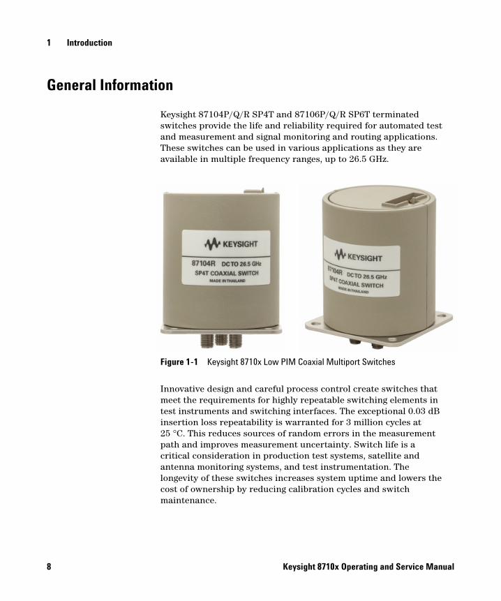
Keysight 87104P/Q/R SP4T and 87106P/Q/R SP6T terminated switches provide the life and reliability required for automated test and measurement and signal monitoring and routing applications. These switches can be used in various applications as they are available in multiple frequency ranges, up to 26.5 GHz.
Innovative design and careful process control create switches that meet the requirements for highly repeatable switching elements in test instruments and switching interfaces. The exceptional 0.03 dB insertion loss repeatability is warranted for 3 million cycles at 25 °C. This reduces sources of random errors in the measurement path and improves measurement uncertainty. Switch life is a critical consideration in production test systems, satellite and antenna monitoring systems, and test instrumentation. The longevity of these switches increases system uptime and lowers the cost of ownership by reducing calibration cycles and switch maintenance.
Figure 1-1 Keysight 8710x Low PIM Coaxial Multiport Switches
8 Keysight 8710x Operating and Service Manual
Introduction 1
Key Features
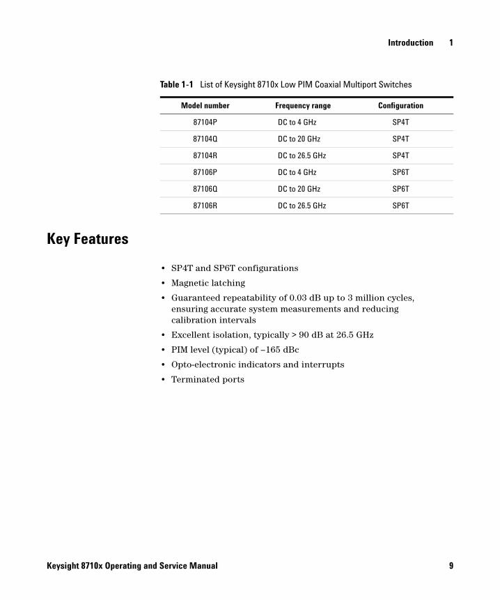
• SP4T and SP6T configurations
• Magnetic latching
• Guaranteed repeatability of 0.03 dB up to 3 million cycles, ensuring accurate system measurements and reducing calibration intervals
• Excellent isolation, typically > 90 dB at 26.5 GHz
• PIM level (typical) of –165 dBc
• Opto-electronic indicators and interrupts
• Terminated ports
Table 1-1 List of Keysight 8710x Low PIM Coaxial Multiport Switches
Model number Frequency range Configuration
87104P DC to 4 GHz SP4T
87104Q DC to 20 GHz SP4T
87104R DC to 26.5 GHz SP4T
87106P DC to 4 GHz SP6T
87106Q DC to 20 GHz SP6T
87106R DC to 26.5 GHz SP6T
Keysight 8710x Operating and Service Manual 9

1 Introduction
This page is intentionally left blank.
10 Keysight 8710x Operating and Service Manual
Keysight 8710x Low PIM Coaxial Multiport SwitchesOperating and Service Manual
2Switch Configuration
Driving the Switch 12
Standard Drive 13
TTL Drive (Option T24) 14
Electronic Position Indicators 15
This chapter provides you information on how to drive the switches using standard drive and TTL drive. Also included is the configuration to utilize the function of the position indicator.
2 Switch Configuration
Driving the Switch
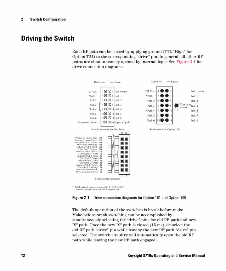
Each RF path can be closed by applying ground (TTL “High” for Option T24) to the corresponding “drive” pin. In general, all other RF paths are simultaneously opened by internal logic. See Figure 2-1 for drive connection diagrams.
The default operation of the switches is break-before-make. Make-before-break switching can be accomplished by simultaneously selecting the “drive” pins for old RF path and new RF path. Once the new RF path is closed (15 ms), de-select the old RF path “drive” pin while leaving the new RF path “drive” pin selected. The switch circuitry will automatically open the old RF path while leaving the new RF path engaged.
Figure 2-1 Drive connection diagrams for Option 161 and Option 100
Drive Sense
Commonground
Ind. Comm.
Ind. 1
Ind. 2
Ind. 3
Ind. 4
Ind. 5
Ind. 6
+24 Vdc
*Path 1
Path 2
Path 3
*Path 4
Path 5
Path 6
10
12
14
2
4
6
8
15
1
3
5
7
9
11
13
15 16
Common Ground (Green - 15)Indicator Path 6 (Yellow - 14)
Drive Path 5 (Brown - 11)Indicator Path 4 (Black - 10)
Indicator Path 3 (Gray - 8)
Drive Path 2 (Green - 5)Indicator Path 1 (Yellow - 4)
** Open all paths (Blue - 16)
Drive Path 3 (Violet - 7)
Drive Path 6 (Orange - 13)Indicator Path 5 (Red - 12)
*Drive Path 4 (White - 9)
Indicator Path 2 (Blue - 6)
*Drive Path 1 (Orange - 3)Indicator Common (Red - 2)Drive Common (Brown - 1)
Drive Sense
Ind. comm.
Open all paths
+24 Vdc
*Path 1
Path 2
Path 3
*Path 4
Path 5
Path 6
Common Ground
1 2
Ind. 13 4
Ind. 25 6
Ind. 37 8
Ind. 49 10
Ind. 511 12
Ind. 613 14
Switch connector (Option 161)
Mating cable connector
15 16
1 2
Solder terminal (Option 100)
* Path1 and path 4 are not connected for 87104A/B/0C/D** “Open all paths pin is not available for option 100
12 Keysight 8710x Operating and Service Manual
Switch Configuration 2
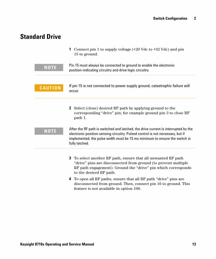
Standard Drive
1 Connect pin 1 to supply voltage (+20 Vdc to +32 Vdc) and pin 15 to ground.
2 Select (close) desired RF path by applying ground to the corresponding “drive” pin; for example ground pin 3 to close RF path 1.
3 To select another RF path, ensure that all unwanted RF path “drive” pins are disconnected from ground (to prevent multiple RF path engagement). Ground the “drive” pin which corresponds to the desired RF path.
4 To open all RF paths, ensure that all RF path “drive” pins are disconnected from ground. Then, connect pin 16 to ground. This feature is not available in option 100.
NOTE Pin 15 must always be connected to ground to enable the electronic position-indicating circuitry and drive logic circuitry.
CAUTION If pin 15 is not connected to power supply ground, catastrophic failure will occur.
NOTE After the RF path is switched and latched, the drive current is interrupted by the electronic position-sensing circuitry. Pulsed control is not necessary, but if implemented, the pulse width must be 15 ms minimum to ensure the switch is fully latched.
Keysight 8710x Operating and Service Manual 13
2 Switch Configuration
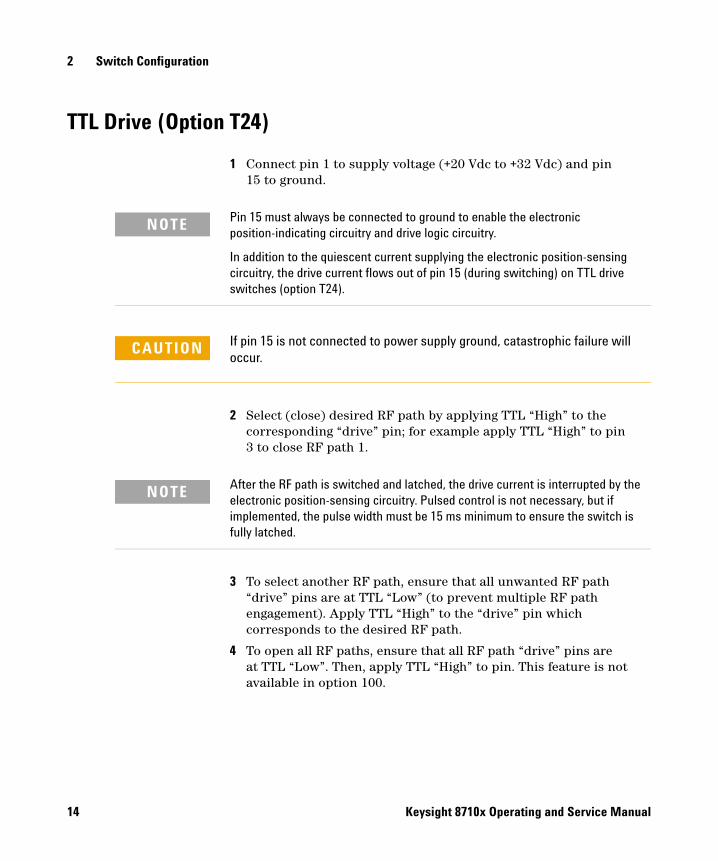
TTL Drive (Option T24)
1 Connect pin 1 to supply voltage (+20 Vdc to +32 Vdc) and pin 15 to ground.
2 Select (close) desired RF path by applying TTL “High” to the corresponding “drive” pin; for example apply TTL “High” to pin 3 to close RF path 1.
3 To select another RF path, ensure that all unwanted RF path “drive” pins are at TTL “Low” (to prevent multiple RF path engagement). Apply TTL “High” to the “drive” pin which corresponds to the desired RF path.
4 To open all RF paths, ensure that all RF path “drive” pins are at TTL “Low”. Then, apply TTL “High” to pin. This feature is not available in option 100.
NOTE Pin 15 must always be connected to ground to enable the electronic position-indicating circuitry and drive logic circuitry.
In addition to the quiescent current supplying the electronic position-sensing circuitry, the drive current flows out of pin 15 (during switching) on TTL drive switches (option T24).
CAUTION If pin 15 is not connected to power supply ground, catastrophic failure will occur.
NOTE After the RF path is switched and latched, the drive current is interrupted by the electronic position-sensing circuitry. Pulsed control is not necessary, but if implemented, the pulse width must be 15 ms minimum to ensure the switch is fully latched.
14 Keysight 8710x Operating and Service Manual
Switch Configuration 2
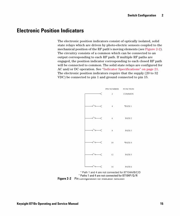
Electronic Position Indicators
The electronic position indicators consist of optically isolated, solid state relays which are driven by photo-electric sensors coupled to the mechanical position of the RF path’s moving elements (see Figure 2-2). The circuitry consists of a common which can be connected to an output corresponding to each RF path. If multiple RF paths are engaged, the position indicator corresponding to each closed RF path will be connected to common. The solid state relays are configured for AC and/or DC operation. See “Indicator Specifications” on page 21. The electronic position indicators require that the supply (20 to 32 VDC) be connected to pin 1 and ground connected to pin 15.
Figure 2-2 Pin configuration for indicator function
s
s
s
s
s
s
PIN NUMBER FUNCTION
2
4
6
8
10
12
14
COMMON
PATH 1
PATH 2
PATH 3
PATH 4
PATH 5
PATH 6
*
*
* Path 1 and 4 are not connected for 87104A/B/C/D
* Paths 1 and 4 are not connected for 87104P/Q/R
Keysight 8710x Operating and Service Manual 15

2 Switch Configuration
This page is intentionally left blank.
16 Keysight 8710x Operating and Service Manual
Keysight 8710x Low PIM Coaxial Multiport SwitchesOperating and Service Manual
3Specifications
General Specifications 18
Supplemental specifications (cold switching) 18
RF Specifications 20
Indicator Specifications 21
Switch Drive Specifications 22
TTL drive (option T24) 22
Environmental Specifications 23
Physical Specifications 24
This chapter provides the specifications of the switches.
Specifications refer to the performance standards or limits against which the coaxial multiport switches are tested.
Typical characteristics are included for additional information only and they are not specifications. These are denoted as “typical”, “nominal”, or “approximate” and are printed in italics.
3 Specifications
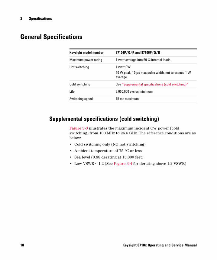
General Specifications
Supplemental specifications (cold switching)
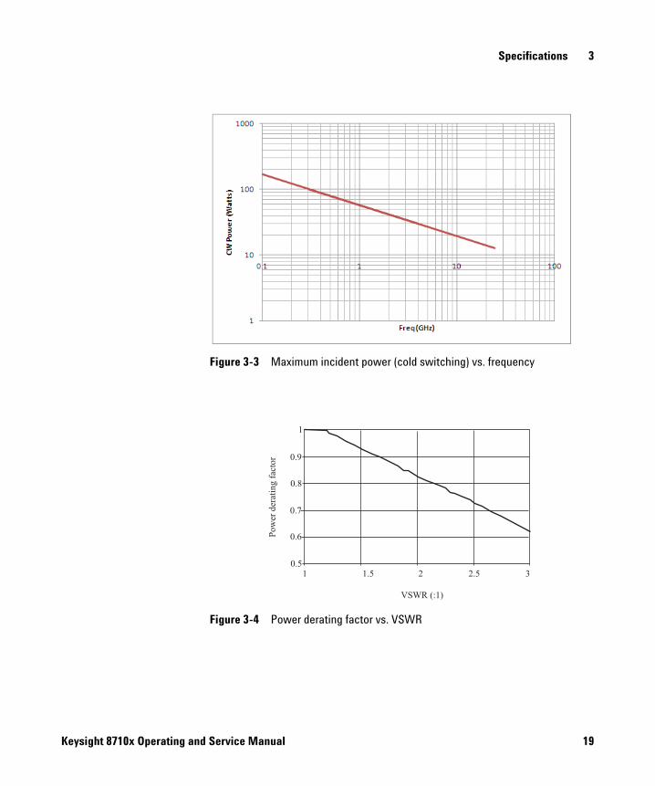
Figure 3-3 illustrates the maximum incident CW power (cold switching) from 100 MHz to 26.5 GHz. The reference conditions are as below:
• Cold switching only (NO hot switching)
• Ambient temperature of 75 °C or less
• Sea level (0.88 derating at 15,000 feet)
• Low VSWR < 1.2 (See Figure 3-4 for derating above 1.2 VSWR)
Keysight model number 87104P/Q/R and 87106P/Q/R
Maximum power rating 1 watt average into 50 Ω internal loads
Hot switching 1 watt CW
50 W peak, 10 μs max pulse width, not to exceed 1 W average.
Cold switching See “Supplemental specifications (cold switching)”
Life 3,000,000 cycles minimum
Switching speed 15 ms maximum
18 Keysight 8710x Operating and Service Manual
Specifications 3
Figure 3-3 Maximum incident power (cold switching) vs. frequency
Figure 3-4 Power derating factor vs. VSWR
Po
wer
der
atin
gfa
cto
r
VSWR (:1)
1 1.5 2 2.5 3
1
0.9
0.8
0.7
0.6
0.5
Keysight 8710x Operating and Service Manual 19
3 Specifications
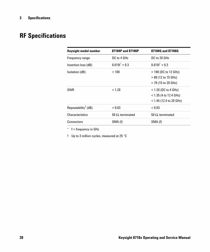
RF Specifications
Keysight model number 87104P and 87106P 87104Q and 87106Q
Frequency range DC to 4 GHz DC to 20 GHz
Insertion loss (dB) 0.015f* + 0.3
* f = frequency in GHz
0.015f* + 0.3
Isolation (dB) > 100 > 100 (DC to 12 GHz)
> 80 (12 to 15 GHz)
> 70 (15 to 20 GHz)
SWR < 1.20 < 1.20 (DC to 4 GHz)
< 1.35 (4 to 12.4 GHz)
< 1.45 (12.4 to 20 GHz)
Repeatability† (dB)
† Up to 3 million cycles, measured at 25 °C
< 0.03 < 0.03
Characteristics 50 Ω, terminated 50 Ω, terminated
Connectors SMA (f) SMA (f)
20 Keysight 8710x Operating and Service Manual
Specifications 3
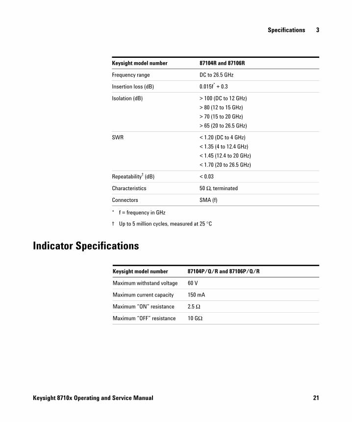
Indicator Specifications
Keysight model number 87104R and 87106R
Frequency range DC to 26.5 GHz
Insertion loss (dB) 0.015f* + 0.3
* f = frequency in GHz
Isolation (dB) > 100 (DC to 12 GHz)
> 80 (12 to 15 GHz)
> 70 (15 to 20 GHz)
> 65 (20 to 26.5 GHz)
SWR < 1.20 (DC to 4 GHz)
< 1.35 (4 to 12.4 GHz)
< 1.45 (12.4 to 20 GHz)
< 1.70 (20 to 26.5 GHz)
Repeatability† (dB)
† Up to 5 million cycles, measured at 25 °C
< 0.03
Characteristics 50 Ω, terminated
Connectors SMA (f)
Keysight model number 87104P/Q/R and 87106P/Q/R
Maximum withstand voltage 60 V
Maximum current capacity 150 mA
Maximum “ON” resistance 2.5 Ω
Maximum “OFF” resistance 10 GΩ
Keysight 8710x Operating and Service Manual 21
3 Specifications
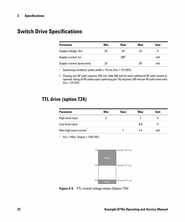
Switch Drive Specifications
TTL drive (option T24)
Parameter Min Nom Max Unit
Supply voltage, Vcc 20 24 32 V
Supply current, Icc*
* Switching condition: pulse width ≥ 15 ms (Vcc = 24 VDC).
200†
† Closing one RF path requires 200 mA. Add 200 mA for each additional RF path closed or opened. Using all RF paths open (selecting pin 16) requires 200 mA per RF path reset with Vcc = 24 VDC.
mA
Supply current (quiescent) 25 50 mA
Parameter Min Nom Max Unit
High level input 3 7 V
Low level input 0.8 V
Max high input current*
* Vcc = Max. Vinput = 3.85 VDC.
1 1.4 mA
Figure 3-5 TTL control voltage states (Option T24)
7.0
3.0
0.8
Maximum state“ON”
Minimum state“ON”
Maximum state”OFF”
“ ”High
“ ‘Low
22 Keysight 8710x Operating and Service Manual
Specifications 3
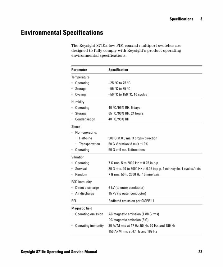
Environmental Specifications
The Keysight 8710x low PIM coaxial multiport switches are designed to fully comply with Keysight’s product operating environmental specifications.
Parameter Specification
Temperature
• Operating
• Storage
• Cycling
–25 °C to 75 °C
–55 °C to 85 °C
–50 °C to 150 °C, 10 cycles
Humidity
• Operating
• Storage
• Condensation
40 °C/95% RH, 5 days
65 °C/90% RH, 24 hours
40 °C/95% RH
Shock
• Non-operating:
• Half-sine
• Transportation
• Operating
500 G at 0.5 ms, 3 drops/direction
50 G Vibration: 8 m/s ±10%
50 G at 6 ms, 6 directions
Vibration
• Operating
• Survival
• Random
7 G rms, 5 to 2000 Hz at 0.25 in p-p
20 G rms, 20 to 2000 Hz at 0.06 in p-p, 4 min/cycle, 4 cycles/axis
7 G rms, 50 to 2000 Hz, 15 min/axis
ESD immunity
• Direct discharge
• Air discharge
6 kV (to outer conductor)
15 kV (to outer conductor)
RFI Radiated emission per CISPR 11
Magnetic field
• Operating emission
• Operating immunity
AC magnetic emission (1.88 G rms)
DC magnetic emission (5 G)
30 A/M rms at 47 Hz, 50 Hz, 60 Hz, and 189 Hz
150 A/M rms at 47 Hz and 189 Hz
Keysight 8710x Operating and Service Manual 23
3 Specifications
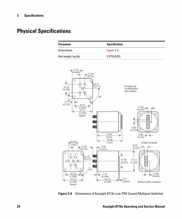
Physical Specifications
Parameter Specification
Dimensions Figure 3-6
Net weight, kg (lb) 0.370 (0.82)
Figure 3-6 Dimensions of Keysight 8710x Low PIM Coaxial Multiport Switches
24 Keysight 8710x Operating and Service Manual
Keysight 8710x Low PIM Coaxial Multiport SwitchesOperating and Service Manual
4Installation and Verification
Installation 26
Initial inspection 26
Operating and Service Instructions 27
Operator’s check 27
Performance test 28
Service instructions 28
This chapter provides you installation information and simple verification steps of the switches.
4 Installation and Verification
Installation
Initial inspection
1 Inspect the shipping container for damage. If the shipping container or cushioning material is damaged, it should be kept until the contents of the shipment have been checked for completeness and the instrument has been checked both mechanically and electrically.
• Check for mechanical damage such as scratches or dents.
• Procedures for checking electrical performance are given under “Operator’s check” on page 27 or “Performance test” on page 28.
2 If the contents are incomplete, there is mechanical damage or defect, or the instrument does not pass the electrical performance test, contact the nearest Keysight Sales and Service office (refer to “Contacting Keysight” on page 4). Keysight will arrange for repair or replacement of the damaged or defective equipment. Keep the shipping materials for the carrier’s inspection.
3 If you are returning the instrument under warranty or for service, repackaging the instrument requires original shipping containers and materials or their equivalents. Keysight can provide packaging materials identical to the original materials. Refer to “Contacting Keysight” on page 4 for the Keysight office nearest to you. Attach a tag indicating the type of service required, return address, model number, and serial number. Mark the container FRAGILE to insure careful handling. In any correspondence, refer to the instrument by its model number and serial number.
26 Keysight 8710x Operating and Service Manual
Installation and Verification 4
Operating and Service Instructions
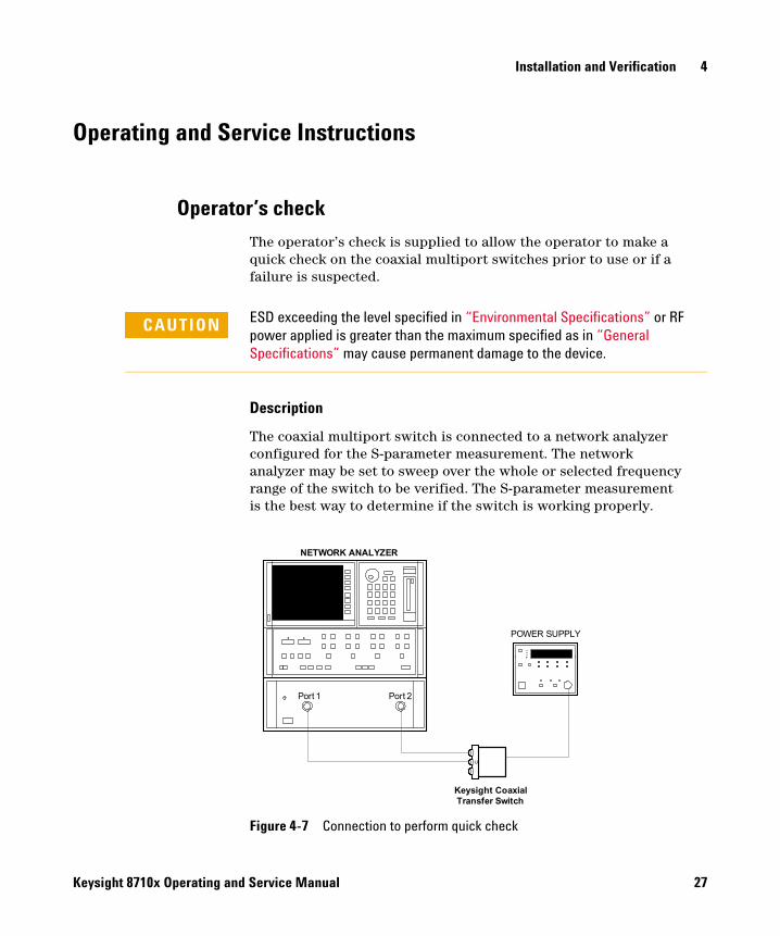
Operator’s check
The operator’s check is supplied to allow the operator to make a quick check on the coaxial multiport switches prior to use or if a failure is suspected.
Description
The coaxial multiport switch is connected to a network analyzer configured for the S-parameter measurement. The network analyzer may be set to sweep over the whole or selected frequency range of the switch to be verified. The S-parameter measurement is the best way to determine if the switch is working properly.
CAUTION ESD exceeding the level specified in “Environmental Specifications” or RF power applied is greater than the maximum specified as in “General Specifications” may cause permanent damage to the device.
Figure 4-7 Connection to perform quick check
NETWORK ANALYZER
C
Keysight Coaxial Transfer Switch
Port 1 Port 2
POWER SUPPLY
Keysight 8710x Operating and Service Manual 27
4 Installation and Verification
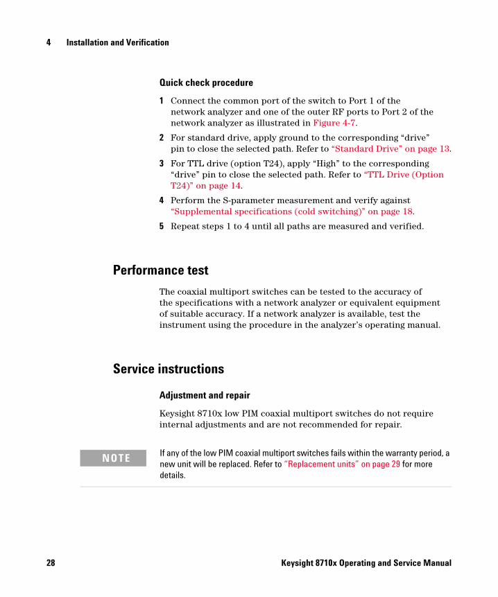
Quick check procedure
1 Connect the common port of the switch to Port 1 of the network analyzer and one of the outer RF ports to Port 2 of the network analyzer as illustrated in Figure 4-7.
2 For standard drive, apply ground to the corresponding “drive” pin to close the selected path. Refer to “Standard Drive” on page 13.
3 For TTL drive (option T24), apply “High” to the corresponding “drive” pin to close the selected path. Refer to “TTL Drive (Option T24)” on page 14.
4 Perform the S-parameter measurement and verify against “Supplemental specifications (cold switching)” on page 18.
5 Repeat steps 1 to 4 until all paths are measured and verified.
Performance test
The coaxial multiport switches can be tested to the accuracy of the specifications with a network analyzer or equivalent equipment of suitable accuracy. If a network analyzer is available, test the instrument using the procedure in the analyzer’s operating manual.
Service instructions
Adjustment and repair
Keysight 8710x low PIM coaxial multiport switches do not require internal adjustments and are not recommended for repair.
NOTE If any of the low PIM coaxial multiport switches fails within the warranty period, a new unit will be replaced. Refer to “Replacement units” on page 29 for more details.
28 Keysight 8710x Operating and Service Manual
Installation and Verification 4
Maintenance
The connectors, particularly the connector faces, must be kept clean. For instructions on connecting and care of your connectors, refer to the Microwave Connector Care Quick Reference Card (08510-90360).
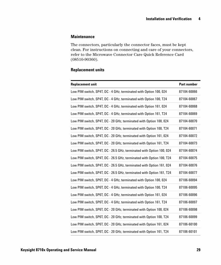
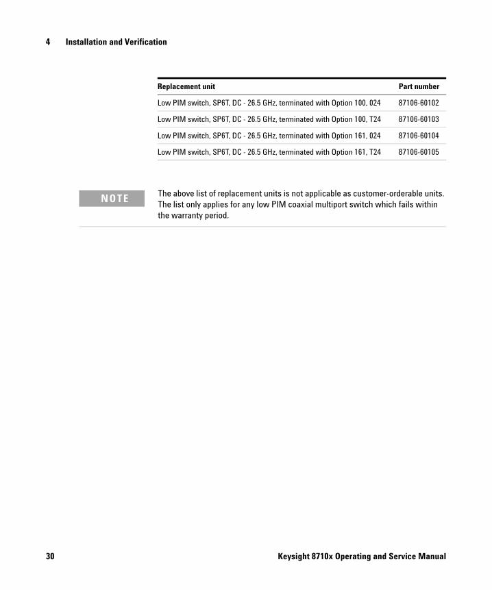
Replacement units
Replacement unit Part number
Low PIM switch, SP4T, DC - 4 GHz, terminated with Option 100, 024 87104-60066
Low PIM switch, SP4T, DC - 4 GHz, terminated with Option 100, T24 87104-60067
Low PIM switch, SP4T, DC - 4 GHz, terminated with Option 161, 024 87104-60068
Low PIM switch, SP4T, DC - 4 GHz, terminated with Option 161, T24 87104-60069
Low PIM switch, SP4T, DC - 20 GHz, terminated with Option 100, 024 87104-60070
Low PIM switch, SP4T, DC - 20 GHz, terminated with Option 100, T24 87104-60071
Low PIM switch, SP4T, DC - 20 GHz, terminated with Option 161, 024 87104-60072
Low PIM switch, SP4T, DC - 20 GHz, terminated with Option 161, T24 87104-60073
Low PIM switch, SP4T, DC - 26.5 GHz, terminated with Option 100, 024 87104-60074
Low PIM switch, SP4T, DC - 26.5 GHz, terminated with Option 100, T24 87104-60075
Low PIM switch, SP4T, DC - 26.5 GHz, terminated with Option 161, 024 87104-60076
Low PIM switch, SP4T, DC - 26.5 GHz, terminated with Option 161, T24 87104-60077
Low PIM switch, SP6T, DC - 4 GHz, terminated with Option 100, 024 87106-60094
Low PIM switch, SP6T, DC - 4 GHz, terminated with Option 100, T24 87106-60095
Low PIM switch, SP6T, DC - 4 GHz, terminated with Option 161, 024 87106-60096
Low PIM switch, SP6T, DC - 4 GHz, terminated with Option 161, T24 87106-60097
Low PIM switch, SP6T, DC - 20 GHz, terminated with Option 100, 024 87106-60098
Low PIM switch, SP6T, DC - 20 GHz, terminated with Option 100, T24 87106-60099
Low PIM switch, SP6T, DC - 20 GHz, terminated with Option 161, 024 87106-60100
Low PIM switch, SP6T, DC - 20 GHz, terminated with Option 161, T24 87106-60101
Keysight 8710x Operating and Service Manual 29
4 Installation and Verification
Low PIM switch, SP6T, DC - 26.5 GHz, terminated with Option 100, 024 87106-60102
Low PIM switch, SP6T, DC - 26.5 GHz, terminated with Option 100, T24 87106-60103
Low PIM switch, SP6T, DC - 26.5 GHz, terminated with Option 161, 024 87106-60104
Low PIM switch, SP6T, DC - 26.5 GHz, terminated with Option 161, T24 87106-60105
Replacement unit Part number
NOTE The above list of replacement units is not applicable as customer-orderable units. The list only applies for any low PIM coaxial multiport switch which fails within the warranty period.
30 Keysight 8710x Operating and Service Manual

This information is subject to change without notice.© Keysight Technologies 2014
Edition 2, October 2014
*87104-80017*87104-80017
www.keysight.com