Embed Size (px)
Citation preview
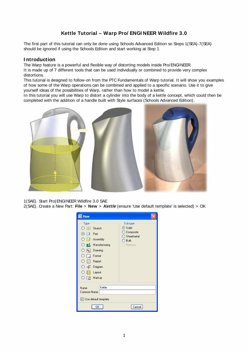
Kettle Tutorial – Warp Pro/ENGINEER Wildfire 3.0
The first part of this tutorial can only be done using Schools Advanced Edition so Steps 1(SEA)-7(SEA) should be ignored if using the Schools Edition and start working at Step 1 Introduction The Warp feature is a powerful and flexible way of distorting models inside Pro/ENGINEER. It is made up of 7 different tools that can be used individually or combined to provide very complex distortions. This tutorial is designed to follow-on from the PTC Fundamentals of Warp tutorial. It will show you examples of how some of the Warp operations can be combined and applied to a specific scenario. Use it to give yourself ideas of the possibilities of Warp, rather than how to model a kettle. In this tutorial you will use Warp to distort a cylinder into the body of a kettle concept, which could then be completed with the addition of a handle built with Style surfaces (Schools Advanced Edition).
1(SAE). Start Pro|ENGINEER Wildfire 3.0 SAE 2(SAE). Create a New Part: File > New > Kettle (ensure ‘Use default template’ is selected) > OK
1
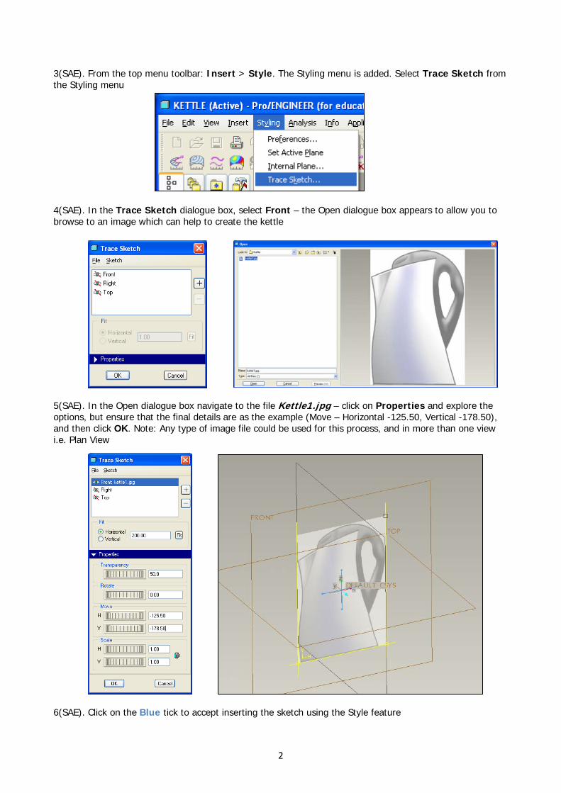
3(SAE). From the top menu toolbar: Insert > Style. The Styling menu is added. Select Trace Sketch from the Styling menu
4(SAE). In the Trace Sketch dialogue box, select Front – the Open dialogue box appears to allow you to browse to an image which can help to create the kettle
5(SAE). In the Open dialogue box navigate to the file Kettle1.jpg – click on Properties and explore the options, but ensure that the final details are as the example (Move – Horizontal -125.50, Vertical -178.50), and then click OK. Note: Any type of image file could be used for this process, and in more than one view i.e. Plan View
6(SAE). Click on the Blue tick to accept inserting the sketch using the Style feature
2
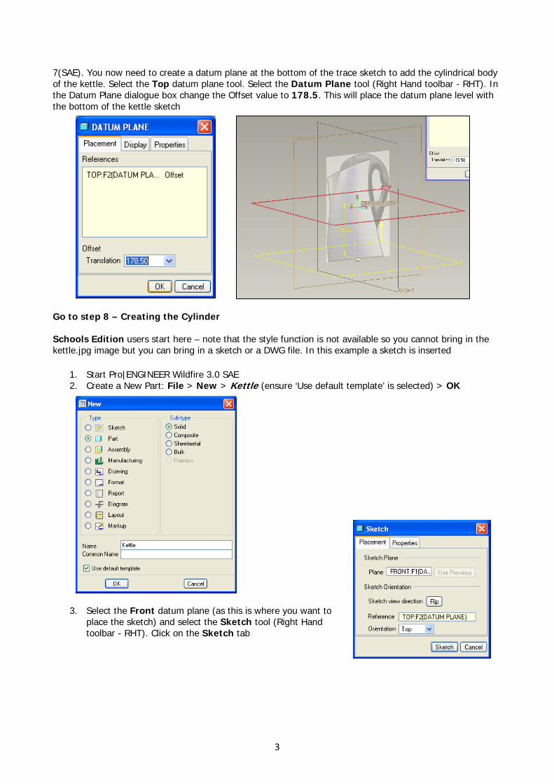
7(SAE). You now need to create a datum plane at the bottom of the trace sketch to add the cylindrical body of the kettle. Select the Top datum plane tool. Select the Datum Plane tool (Right Hand toolbar - RHT). In the Datum Plane dialogue box change the Offset value to 178.5. This will place the datum plane level with the bottom of the kettle sketch
Go to step 8 – Creating the Cylinder Schools Edition users start here – note that the style function is not available so you cannot bring in the kettle.jpg image but you can bring in a sketch or a DWG file. In this example a sketch is inserted
1. Start Pro|ENGINEER Wildfire 3.0 SAE 2. Create a New Part: File > New > Kettle (ensure ‘Use default template’ is selected) > OK
3. Select the Front datum plane (as this is where you want to
place the sketch) and select the Sketch tool (Right Hand toolbar - RHT). Click on the Sketch tab
3
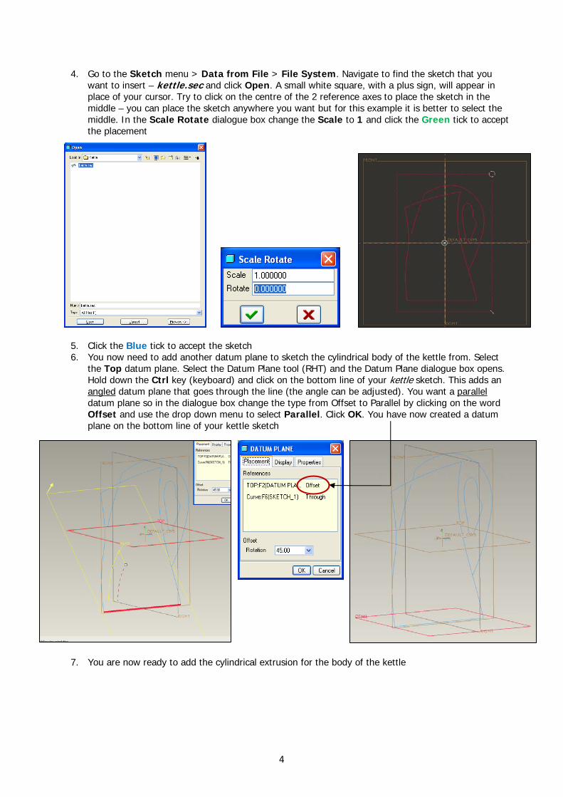
4. Go to the Sketch menu > Data from File > File System. Navigate to find the sketch that you want to insert – kettle.sec and click Open. A small white square, with a plus sign, will appear in place of your cursor. Try to click on the centre of the 2 reference axes to place the sketch in the middle – you can place the sketch anywhere you want but for this example it is better to select the middle. In the Scale Rotate dialogue box change the Scale to 1 and click the Green tick to accept the placement
5. Click the Blue tick to accept the sketch 6. You now need to add another datum plane to sketch the cylindrical body of the kettle from. Select
the Top datum plane. Select the Datum Plane tool (RHT) and the Datum Plane dialogue box opens. Hold down the Ctrl key (keyboard) and click on the bottom line of your kettle sketch. This adds an angled datum plane that goes through the line (the angle can be adjusted). You want a parallel datum plane so in the dialogue box change the type from Offset to Parallel by clicking on the word Offset and use the drop down menu to select Parallel. Click OK. You have now created a datum plane on the bottom line of your kettle sketch
7. You are now ready to add the cylindrical extrusion for the body of the kettle
4
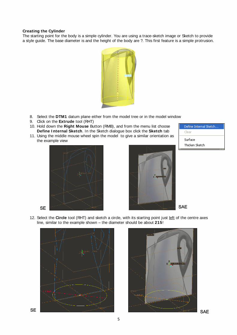
Creating the Cylinder The starting point for the body is a simple cylinder. You are using a trace-sketch image or Sketch to provide a style guide. The base diameter is and the height of the body are ?. This first feature is a simple protrusion.
8. Select the DTM1 datum plane either from the model tree or in the model window 9. Click on the Extrude tool (RHT) 10. Hold down the Right Mouse Button (RMB), and from the menu list choose
Define Internal Sketch. In the Sketch dialogue box click the Sketch tab 11. Using the middle mouse wheel spin the model to give a similar orientation as
the example view
SE SAE
12. Select the Circle tool (RHT) and sketch a circle, with its starting point just left of the centre axes line, similar to the example shown – the diameter should be about 215!
SAESE
5
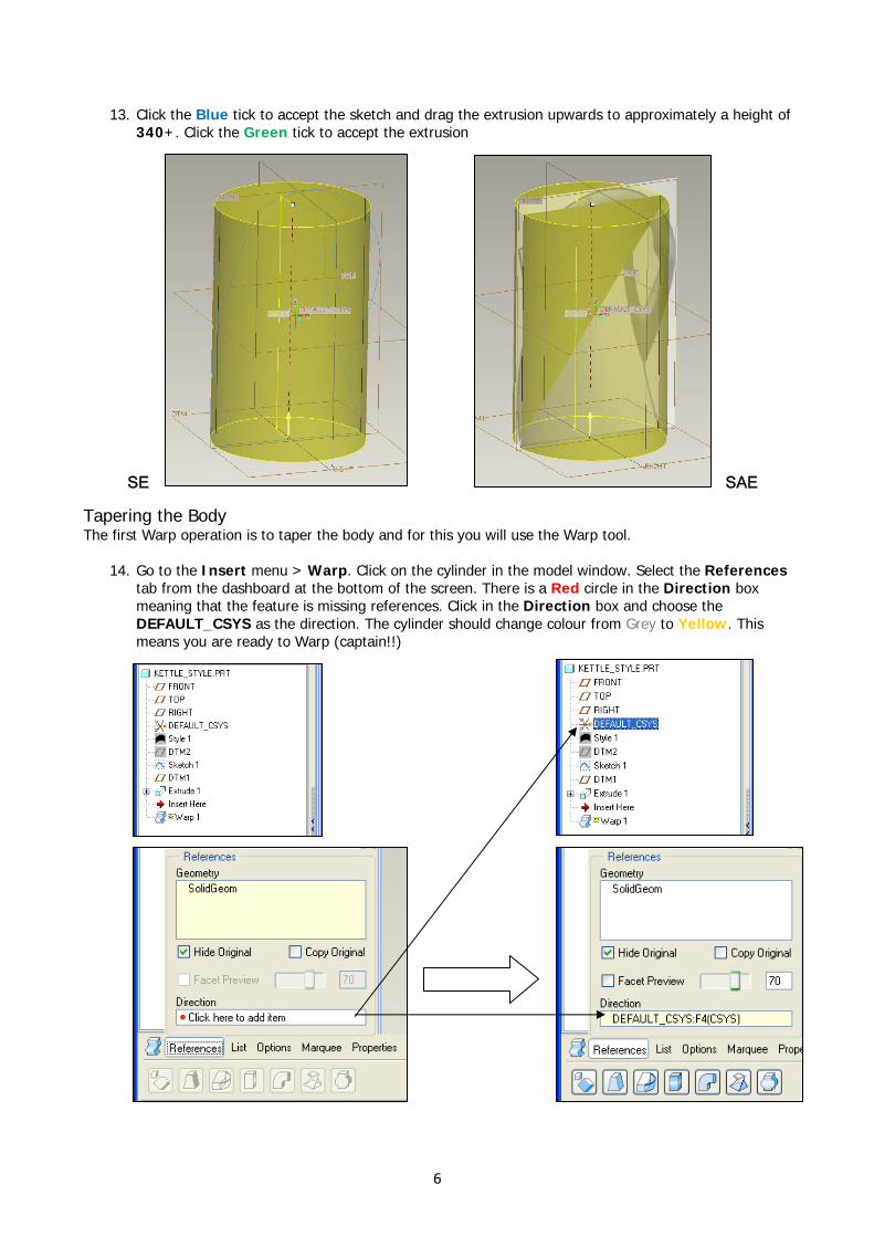
13. Click the Blue tick to accept the sketch and drag the extrusion upwards to approximately a height of 340+. Click the Green tick to accept the extrusion
Tapering the Body The first Warp operation is to taper the body and for this you will use the Warp tool.
14. Go to the Insert menu > Warp. Click on the cylinder in the model window. Select the References tab from the dashboard at the bottom of the screen. There is a Red circle in the Direction box meaning that the feature is missing references. Click in the Direction box and choose the DEFAULT_CSYS as the direction. The cylinder should change colour from Grey to Yellow. This means you are ready to Warp (captain!!)
SAESE
6
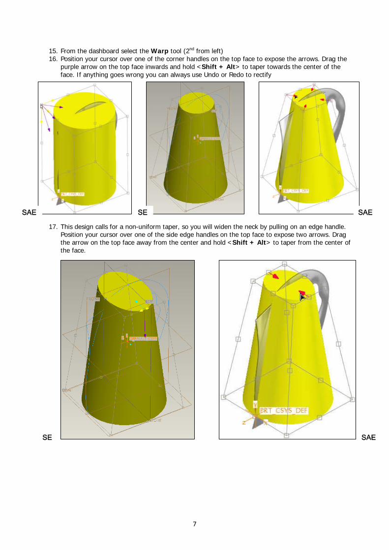
15. From the dashboard select the Warp tool (2nd from left) 16. Position your cursor over one of the corner handles on the top face to expose the arrows. Drag the
purple arrow on the top face inwards and hold <Shift + Alt> to taper towards the center of the face. If anything goes wrong you can always use Undo or Redo to rectify
SAE SE SAE
17. This design calls for a non-uniform taper, so you will widen the neck by pulling on an edge handle. Position your cursor over one of the side edge handles on the top face to expose two arrows. Drag the arrow on the top face away from the center and hold <Shift + Alt> to taper from the center of the face.
SAESE
7
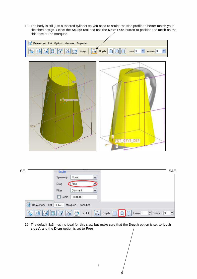
18. The body is still just a tapered cylinder so you need to sculpt the side profile to better match your sketched design. Select the Sculpt tool and use the Next Face button to position the mesh on the side face of the marquee
19. The default 3x3 mesh is ideal for this step, but make sure that the Depth option is set to ‘both
sides’, and the Drag option is set to Free
8
SE SAE
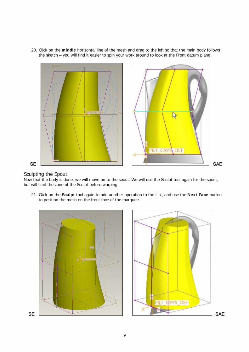
20. Click on the middle horizontal line of the mesh and drag to the left so that the main body follows the sketch – you will find it easier to spin your work around to look at the Front datum plane
SAESE Sculpting the Spout Now that the body is done, we will move on to the spout. We will use the Sculpt tool again for the spout, but will limit the zone of the Sculpt before warping
21. Click on the Sculpt tool again to add another operation to the List, and use the Next Face button to position the mesh on the front face of the marquee
SAESE
9
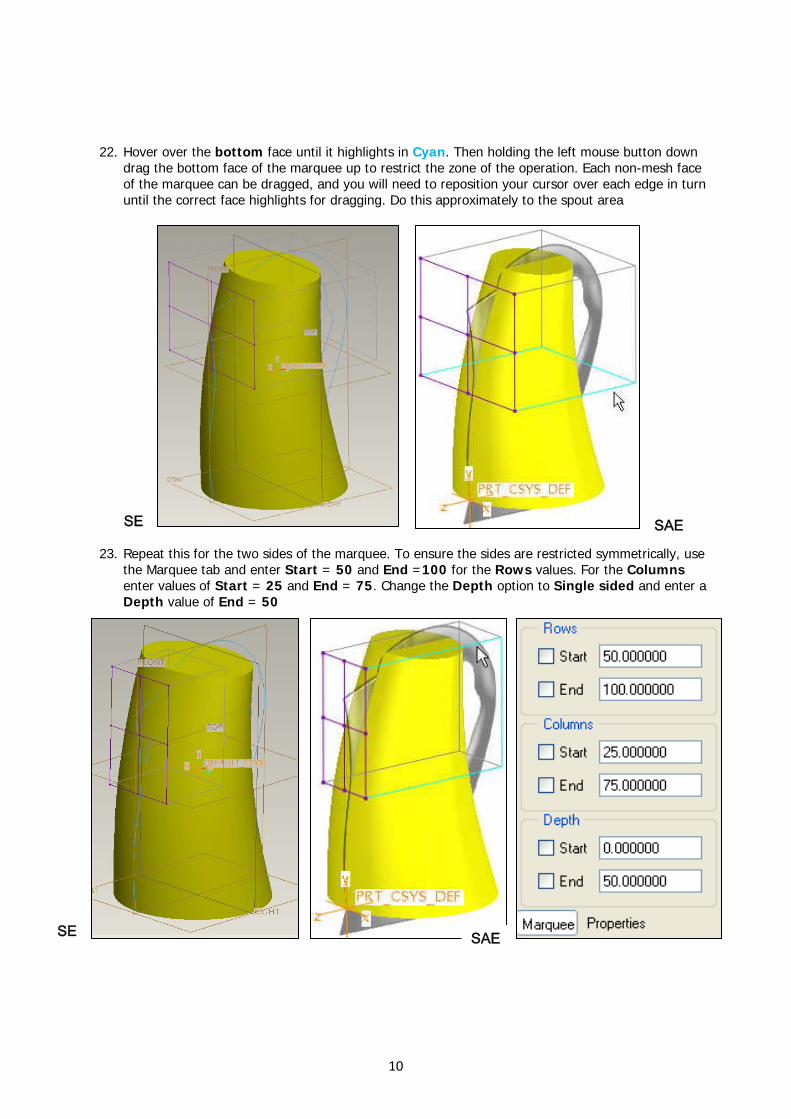
22. Hover over the bottom face until it highlights in Cyan. Then holding the left mouse button down drag the bottom face of the marquee up to restrict the zone of the operation. Each non-mesh face of the marquee can be dragged, and you will need to reposition your cursor over each edge in turn until the correct face highlights for dragging. Do this approximately to the spout area
SE SAE
23. Repeat this for the two sides of the marquee. To ensure the sides are restricted symmetrically, use the Marquee tab and enter Start = 50 and End =100 for the Rows values. For the Columns enter values of Start = 25 and End = 75. Change the Depth option to Single sided and enter a Depth value of End = 50
SAE SE
10
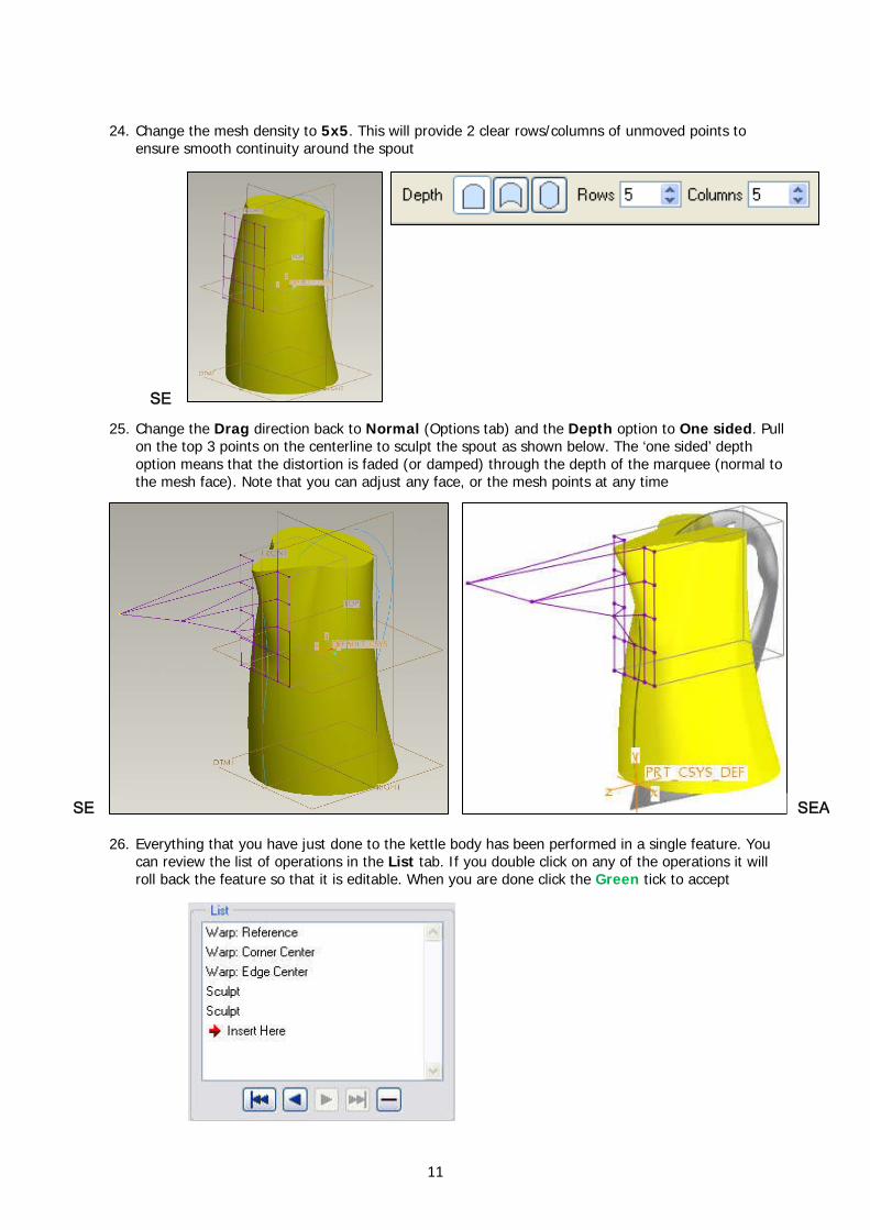
24. Change the mesh density to 5x5. This will provide 2 clear rows/columns of unmoved points to
ensure smooth continuity around the spout
SE
25. Change the Drag direction back to Normal (Options tab) and the Depth option to One sided. Pull on the top 3 points on the centerline to sculpt the spout as shown below. The ‘one sided’ depth option means that the distortion is faded (or damped) through the depth of the marquee (normal to the mesh face). Note that you can adjust any face, or the mesh points at any time
SE SEA
26. Everything that you have just done to the kettle body has been performed in a single feature. You can review the list of operations in the List tab. If you double click on any of the operations it will roll back the feature so that it is editable. When you are done click the Green tick to accept
11
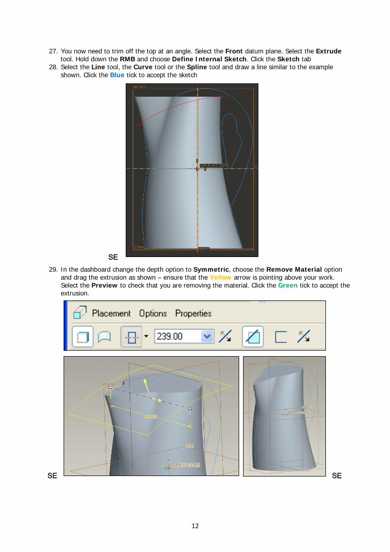
27. You now need to trim off the top at an angle. Select the Front datum plane. Select the Extrude tool. Hold down the RMB and choose Define Internal Sketch. Click the Sketch tab
28. Select the Line tool, the Curve tool or the Spline tool and draw a line similar to the example shown. Click the Blue tick to accept the sketch
SE
29. In the dashboard change the depth option to Symmetric, choose the Remove Material option and drag the extrusion as shown – ensure that the Yellow arrow is pointing above your work. Select the Preview to check that you are removing the material. Click the Green tick to accept the extrusion.
SE SE
12
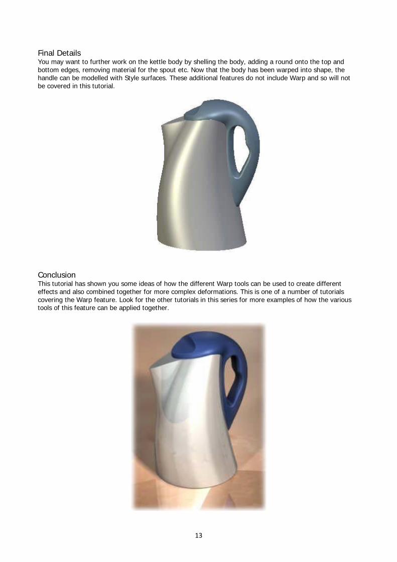
Final Details You may want to further work on the kettle body by shelling the body, adding a round onto the top and bottom edges, removing material for the spout etc. Now that the body has been warped into shape, the handle can be modelled with Style surfaces. These additional features do not include Warp and so will not be covered in this tutorial.
Conclusion This tutorial has shown you some ideas of how the different Warp tools can be used to create different effects and also combined together for more complex deformations. This is one of a number of tutorials covering the Warp feature. Look for the other tutorials in this series for more examples of how the various tools of this feature can be applied together.
13
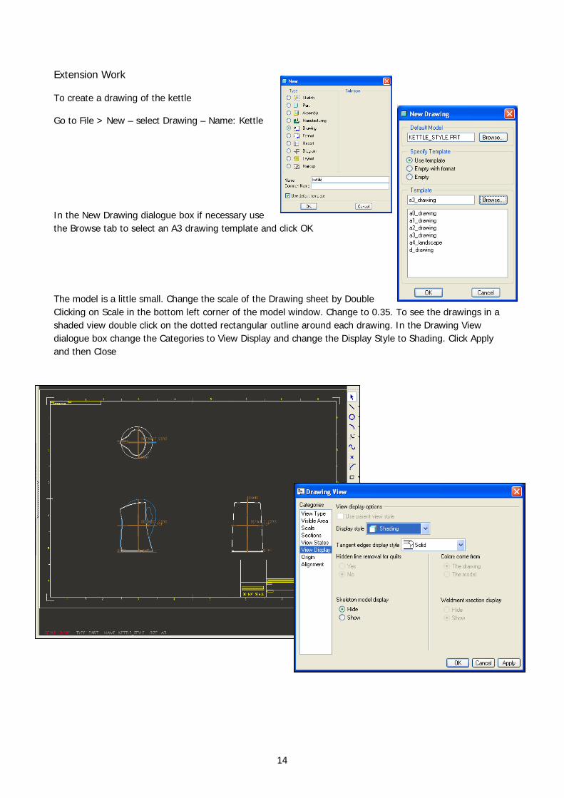
Extension Work
To create a drawing of the kettle
Go to File > New – select Drawing – Name: Kettle
In the New Drawing dialogue box if necessary use the Browse tab to select an A3 drawing template and click OK
The model is a little small. Change the scale of the Drawing sheet by Double Clicking on Scale in the bottom left corner of the model window. Change to 0.35. To see the drawings in a shaded view double click on the dotted rectangular outline around each drawing. In the Drawing View dialogue box change the Categories to View Display and change the Display Style to Shading. Click Apply and then Close
14
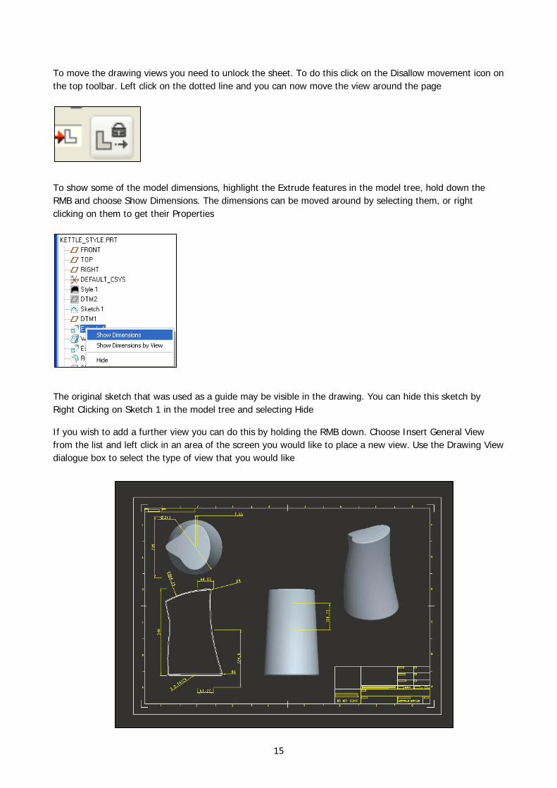
To move the drawing views you need to unlock the sheet. To do this click on the Disallow movement icon on the top toolbar. Left click on the dotted line and you can now move the view around the page
To show some of the model dimensions, highlight the Extrude features in the model tree, hold down the RMB and choose Show Dimensions. The dimensions can be moved around by selecting them, or right clicking on them to get their Properties
The original sketch that was used as a guide may be visible in the drawing. You can hide this sketch by Right Clicking on Sketch 1 in the model tree and selecting Hide
If you wish to add a further view you can do this by holding the RMB down. Choose Insert General View from the list and left click in an area of the screen you would like to place a new view. Use the Drawing View dialogue box to select the type of view that you would like
15