Embed Size (px)
Citation preview
Implementation design for inspectionof O-rings
Under Guidance ofMr. SUFIAN JALILIMANAGER (QA)TML DRIVELINES LIMITED
Under Advisor of Dr. B.KONDA REDDYASST. PROFESSORRGUKT
A summer intern project by S. KESAVULU R101276
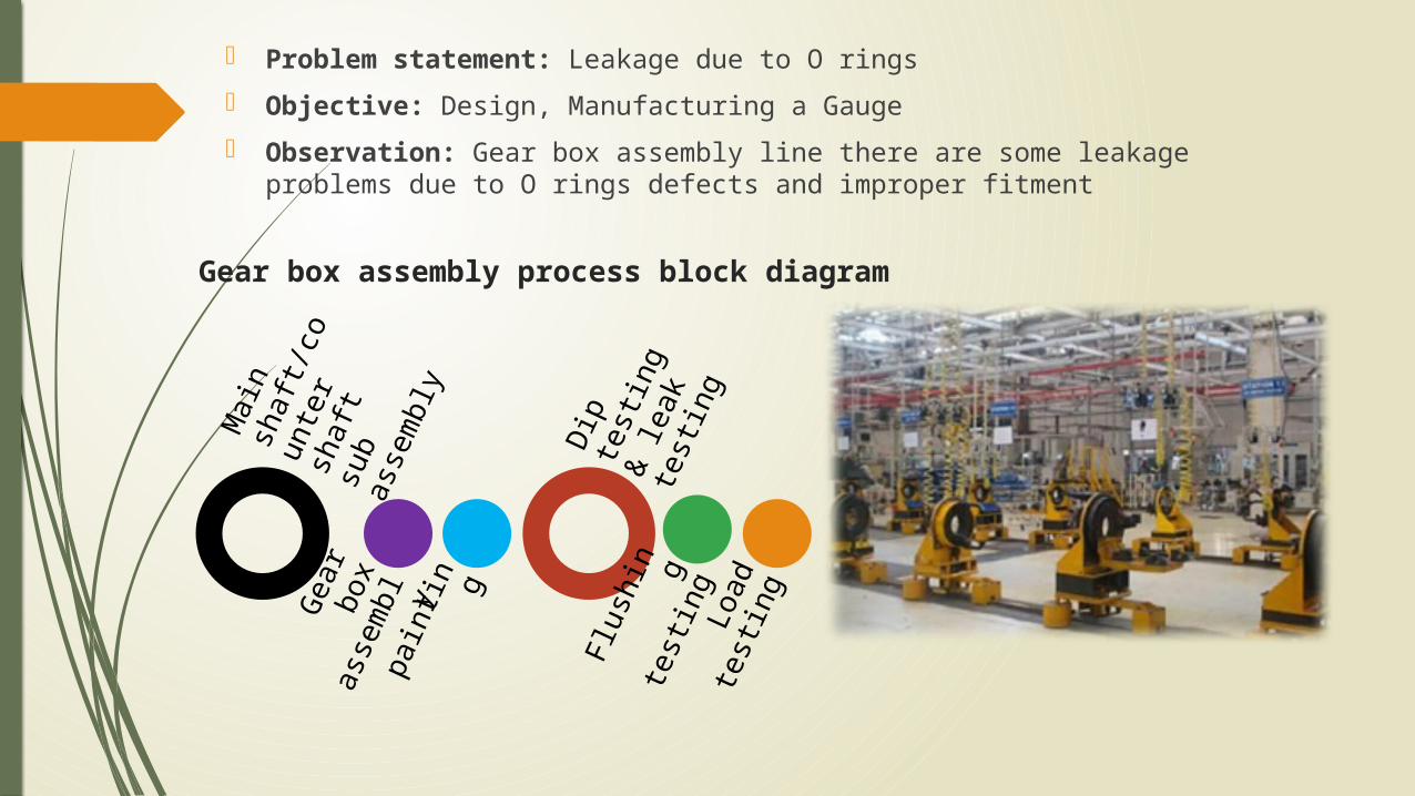
Gear box assembly process block diagram
Problem statement: Leakage due to O rings Objective: Design, Manufacturing a Gauge Observation: Gear box assembly line there are some leakage problems
due to O rings defects and improper fitment
Main
shaf
t/cou
nter
shaf
t su
b as
sem
bly
Gear
box
as
sem
bl ypa
inting
Dip
testi
ng &
lea
k te
sting
Flush
ing
testi
ngLo
ad
testi
ng
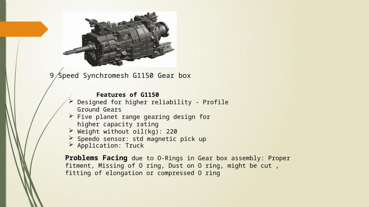
9 Speed Synchromesh G1150 Gear box
Features of G1150 Designed for higher reliability - Profile Ground
Gears Five planet range gearing design for higher
capacity rating Weight without oil(kg): 220 Speedo sensor: std magnetic pick up Application: Truck
Problems Facing due to O-Rings in Gear box assembly: Proper fitment, Missing of O ring, Dust on O ring, might be cut , fitting of elongation or compressed O ring
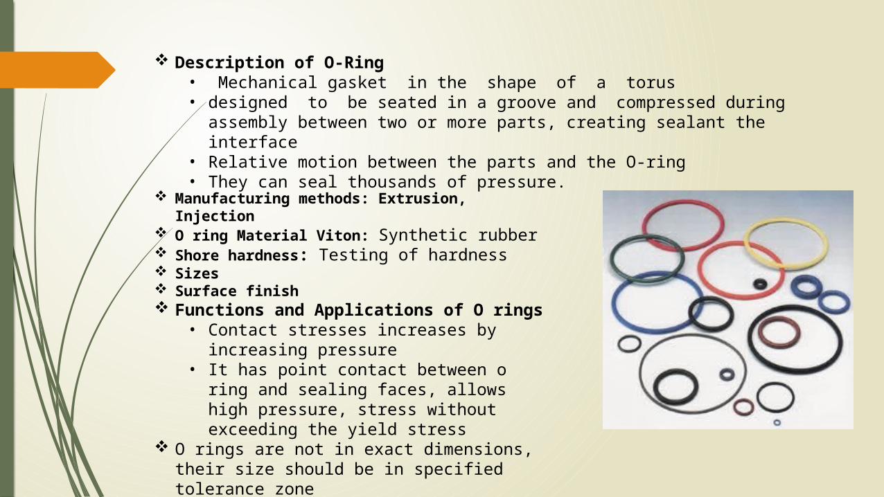
Description of O-Ring• Mechanical gasket in the shape of a torus• designed to be seated in a groove and compressed during assembly
between two or more parts, creating sealant the interface• Relative motion between the parts and the O-ring• They can seal thousands of pressure.
Manufacturing methods: Extrusion, Injection O ring Material Viton: Synthetic rubber Shore hardness: Testing of hardness Sizes Surface finish Functions and Applications of O rings
• Contact stresses increases by increasing pressure
• It has point contact between o ring and sealing faces, allows high pressure, stress without exceeding the yield stress
O rings are not in exact dimensions, their size should be in specified tolerance zone
Quality standards: Check the condition of O ring, proper fitmentInspection Methods of O rings Visual examination and inspection steps
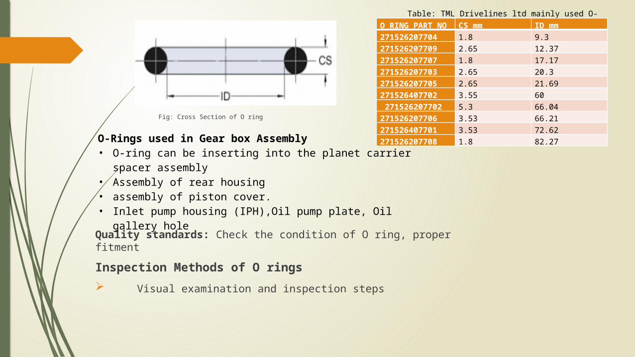
Fig: Cross Section of O ring
Table: TML Drivelines ltd mainly used O-ring sizesO RING PART
NOCS mm ID mm
271526207704 1.8 9.3271526207709 2.65 12.37271526207707 1.8 17.17271526207703 2.65 20.3271526207705 2.65 21.69271526407702 3.55 60 271526207702 5.3 66.04271526207706 3.53 66.21271526407701 3.53 72.62271526207708 1.8 82.27
O-Rings used in Gear box Assembly• O-ring can be inserting into the planet carrier spacer
assembly• Assembly of rear housing• assembly of piston cover.• Inlet pump housing (IPH),Oil pump plate, Oil gallery hole
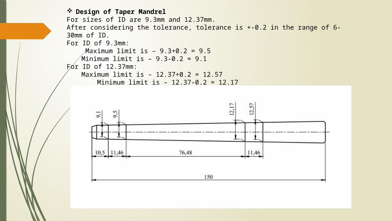
Design of Taper MandrelFor sizes of ID are 9.3mm and 12.37mm. After considering the tolerance, tolerance is +-0.2 in the range of 6-30mm of ID.For ID of 9.3mm:
Maximum limit is – 9.3+0.2 = 9.5Minimum limit is – 9.3-0.2 = 9.1
For ID of 12.37mm: Maximum limit is – 12.37+0.2 = 12.57 Minimum limit is – 12.37-0.2 = 12.17
Conclusion Taper mandrel gauges are exclusive for given 10 different sizes of O rings This taper mandrel gauges measure actual dimension of O ring within
tolerance limits quick results with the specified tolerances Time involved in for inspection is reduced
Laser Marking• Clearly visible, permanently marked, HD marking, Durability• Precise beam positioning and a beam highly localized energy transfer to the work
piece

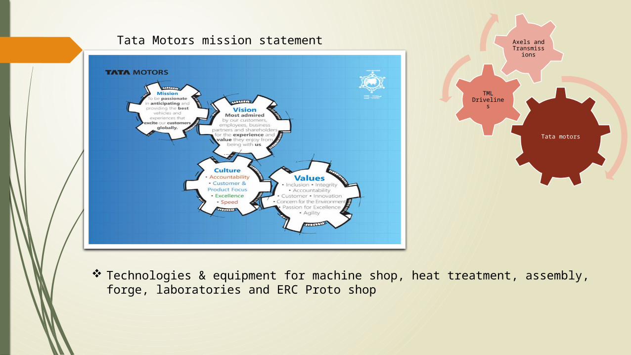
Tata motors
TML Drivelines
Axels and Transmissio
nsTata Motors mission statement
Technologies & equipment for machine shop, heat treatment, assembly, forge, laboratories and ERC Proto shop
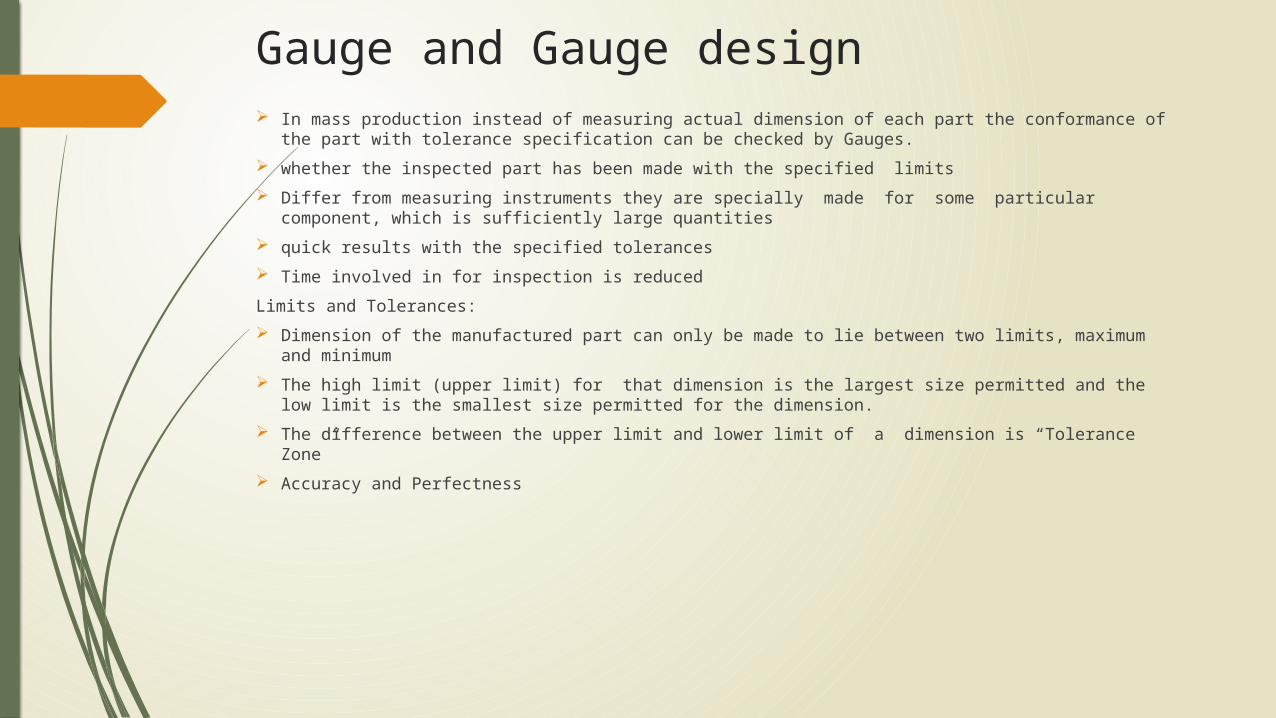
Gauge and Gauge design In mass production instead of measuring actual dimension of each part the conformance of the
part with tolerance specification can be checked by Gauges. whether the inspected part has been made with the specified limits Differ from measuring instruments they are specially made for some particular component,
which is sufficiently large quantities quick results with the specified tolerances Time involved in for inspection is reducedLimits and Tolerances: Dimension of the manufactured part can only be made to lie between two limits, maximum and
minimum The high limit (upper limit) for that dimension is the largest size permitted and the low limit is the
smallest size permitted for the dimension. The difference between the upper limit and lower limit of a dimension is “Tolerance Zone” Accuracy and Perfectness
About TML Drivelines Company profile Machining process involved in gear box Objective of project Introduction about gauge and design Procedure(Including O rings) Design of Taper Mandrels Laser Marking Conclusion
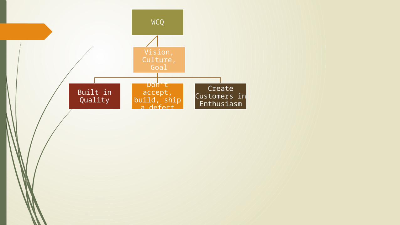
WCQ
Built in Quality
Don’t accept, build, ship a
defect
Create Customers in Enthusiasm
Vision, Culture, Goal