Embed Size (px)
Citation preview
Kerr Effect
Michelle [email protected]
Instituto de Física de São Carlos, Universidade de São Paulo, 13566-590 São Carlos, SP, Bras,il
June 14, 2018
Abstract
In this work we present a theoretical treatment of the Kerr effect based on third-order nonlinear optical processes.When an intense electric field is placed in a media, a birefringence is induced and the refractive index depends on thesquare of the of the amplitude of the electric field. Depending on the nature of the electric field we can describe twophenomena: the electro-optic Kerr effect and the optical Kerr effect. In analogy to these effects we also explore anintroduction to the magneto-optical Kerr effect and some different applications.
1 Introduction
Birefringence was first observed in the 17th century whensailors visiting Iceland brought back to Europe calcitecrystals that showed double images of objects that wereviewed through them. This effect was first described bythe Danish scientist Rasmus Bartholin in 1669. How-ever, it was not until 1823 that Augustin-Jean Fresneldescribed the phenomenon in terms of polarization, un-derstanding light as a wave with field components intransverse polarizations.
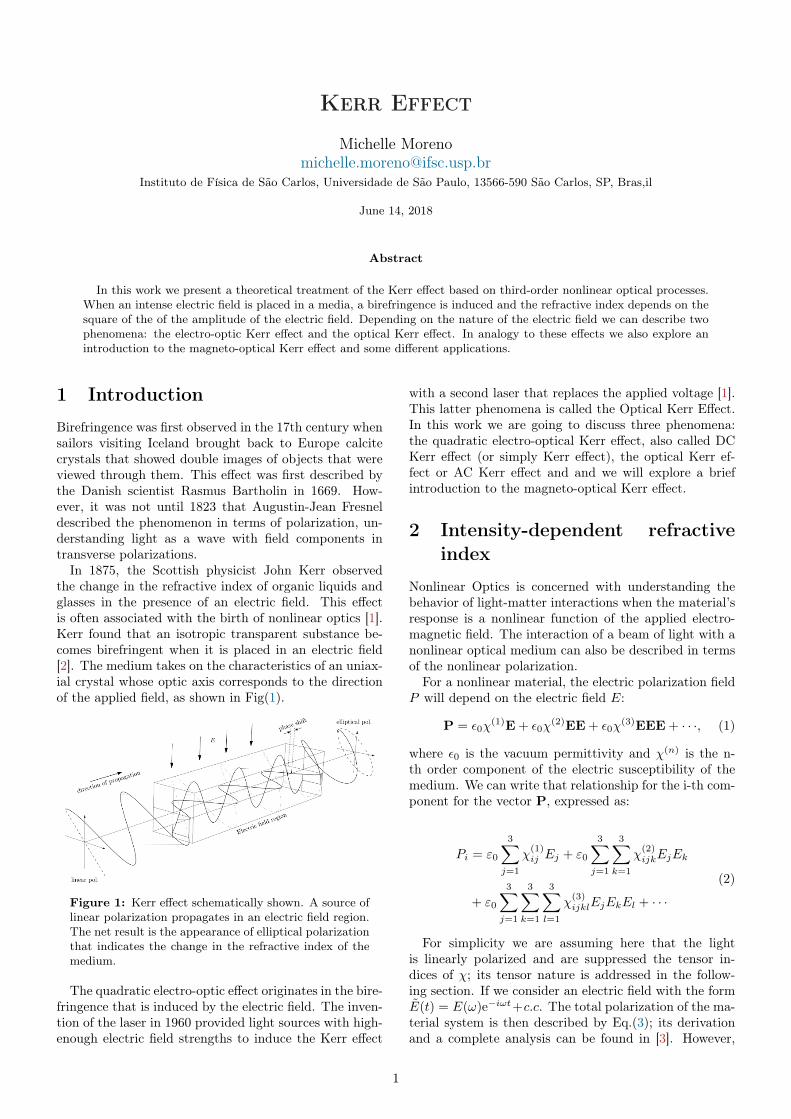
In 1875, the Scottish physicist John Kerr observedthe change in the refractive index of organic liquids andglasses in the presence of an electric field. This effectis often associated with the birth of nonlinear optics [1].Kerr found that an isotropic transparent substance be-comes birefringent when it is placed in an electric field[2]. The medium takes on the characteristics of an uniax-ial crystal whose optic axis corresponds to the directionof the applied field, as shown in Fig(1).
Figure 1: Kerr effect schematically shown. A source oflinear polarization propagates in an electric field region.The net result is the appearance of elliptical polarizationthat indicates the change in the refractive index of themedium.
The quadratic electro-optic effect originates in the bire-fringence that is induced by the electric field. The inven-tion of the laser in 1960 provided light sources with high-enough electric field strengths to induce the Kerr effect
with a second laser that replaces the applied voltage [1].This latter phenomena is called the Optical Kerr Effect.In this work we are going to discuss three phenomena:the quadratic electro-optical Kerr effect, also called DCKerr effect (or simply Kerr effect), the optical Kerr ef-fect or AC Kerr effect and and we will explore a briefintroduction to the magneto-optical Kerr effect.
2 Intensity-dependent refractiveindex
Nonlinear Optics is concerned with understanding thebehavior of light-matter interactions when the material’sresponse is a nonlinear function of the applied electro-magnetic field. The interaction of a beam of light with anonlinear optical medium can also be described in termsof the nonlinear polarization.
For a nonlinear material, the electric polarization fieldP will depend on the electric field E:
P = ε0χ(1)E + ε0χ
(2)EE + ε0χ(3)EEE + · · ·, (1)
where ε0 is the vacuum permittivity and χ(n) is the n-th order component of the electric susceptibility of themedium. We can write that relationship for the i-th com-ponent for the vector P, expressed as:
Pi = ε0
3∑j=1
χ(1)ij Ej + ε0
3∑j=1
3∑k=1
χ(2)ijkEjEk
+ ε0
3∑j=1
3∑k=1
3∑l=1
χ(3)ijklEjEkEl + · · ·
(2)
For simplicity we are assuming here that the lightis linearly polarized and are suppressed the tensor in-dices of χ; its tensor nature is addressed in the follow-ing section. If we consider an electric field with the formE(t) = E(ω)e−iωt+c.c. The total polarization of the ma-terial system is then described by Eq.(3); its derivationand a complete analysis can be found in [3]. However,
1
it is worth pointing out that the different numerical pre-factors in Eq.(3) result from the permutation operationin Eq.(2)
PTOT(ω) = ε0χ(1)E(ω) + 2ε0χ
(2)E(ω)E(0)
+ 3ε0χ(3)|E(ω)|2E(ω) + · · ·
(3)
If we consider the two first terms of Eq.(3), this ap-proximation is known as the linear electro-optic Pockelseffect, which leads to an electric-field induced change inthe refractive index [4]. On the other side, the part of thenonlinear polarization that influences the propagation ofa beam of frequency ω is just given by the third term ofEq.(3), which leads us to the study of the Kerr effect. Inthis case, we can express the polarization as
P (ω) ∼= ε0χ(1)E(ω) + 3ε0χ
(3)|E(ω)|2E(ω)
≡ ε0χeffE(ω),(4)
where we have introduced the effective susceptibilityχeff = χ(1) + 3ε0χ
(3)|E(ω)|2.
Besides that, the refractive index of many optical ma-terials depends on the intensity of the light used to mea-sure it. The refractive index of many materials can bedescribed by the relation [5]
n = n0 + n2
⟨E2⟩, (5)
where n0 represents the usual zero-field or weak-field re-fractive index, and n2 (sometimes called the second-orderindex of refraction) gives the rate at which the refractiveindex increases with the optical intensity. In order torelate the nonlinear susceptibility χ(3) to the nonlinearrefractive index n2, we can take n2 = 1 + χeff . Compar-ing with Eqs.(4) and (5), we can show that the linear andnonlinear refractive indices are related to the linear andnonlinear susceptibilities by
n0 = (1 + χ(1))1/2 (6)
n2 =3χ(3)
4n0. (7)
3 Third-order nonlinear processes
The most general third-order nonlinear process involvesthe interaction of waves at four different frequencies,linked by: ω1 + ω2 + ω3 = ω4. Fortunately, in all com-mon cases, some of the frequencies are the same, andsome may be also zero, or the negatives of the others.The polarization at ω4 is given by
Pi(ω4) =1
2ε0∑p
∑jkl
χ(3)ijkl(ω4;ω1, ω2, ω3)
Ej(ω1)Ek(ω2)El(ω3),
(8)
where ijkl can be x, y or z, and∑
p indicates the right-hand side is to be summed over all distinct permutations
of ω1, ω2 and ω3. This means that the form of the po-larization depends on the frequency arranged and it isspecific of the kind of process. So, for the DC Kerr effectwe have (ω = 0 + 0 + ω)
Pi(ω) = 3ε0∑jkl
χKijkl(ω; 0, 0, ω)Ej(0)Ek(0)El(ω). (9)
This concerns refractive index changes caused by anapplied DC field.
In the optical or AC Kerr effect, an intense beamof light in a medium can itself provide the modulat-ing electric field, without the need for an external fieldto be applied. For the optical Kerr effect we have(ω1 = ω2 − ω2 + ω1)
Pi(ω1) =3
2ε0∑jkl
χOKijkl(ω1;ω2,−ω2, ω1)Ej(ω2)E∗k(ω2)El(ω1).
(10)In this case, the refractive index of an optical wave at
ω1 is modified in the presence of a wave at ω2. It shouldbe also noted that in cases where two (or more) opti-cal waves are involved, these need not necessarily travelin the same direction. There is, for example, no reasonin principle why the two waves in Eq.(10) need to becollinear, and in this case their frequencies could even bethe same.
3.1 Tensor nature of the third order sus-ceptibility
Let us see how to determine the tensor nature of thethird-order susceptibility for the case of an isotropicmaterial such as a glass, a liquid, or a vapor. Webegin by considering the general case in which theapplied frequencies are arbitrary, and we represent thesusceptibility as χijkl ≡ χ
(3)ijkl(ω4 = ω1 + ω2 + ω2). In a
lossless crystal of the most general triclinic symmetry,there are 34 = 81 independent nonlinear coefficients, forother symmetry classes, the number is lower and a listof independent coefficients in each class can be foundin [5]. In an isotropic media, in which all directionsare equivalent, the orientation of the xyz− axes can bechosen to make calculations as simple as possible. Inthis case, only 21 of the 81 coefficients are non-zero, andthese are of four types: type 1 (three members) in whichall indices are identical (χ1 ≡ χiiii), and types 2, 3 and 4(six members each) in which two pairs of indices aree thesame, namely χ2 = χjjkk, χ3 = χjkjk and χ4 = χjkkj
(j 6= k).
The numbering scheme ensures that indices 1 and 2are the same in χ2, indices 1 and 3 in χ3, and 1 and 4 inχ4. Within each type, all members are equal and, as weshall show in a moment, the symmetry of a structurallyisotropic medium imposes the further constraint that
χ1 = χ2 + χ3 + χ4 (11)
In terms of indices, the 21 non-zero coefficients can belisted as follows:
2
1 : xxxx = yyyy = zzzz
2 : xxyy = yyzz = zzxx = yyxx = zzyy = xxzz
3 : xyxy = yzyz = zxzx = yxyx = zyzy = xzxz
4 : xyyx = yzzy = zxxz = yxxy = zyyz = xzzx
(12)
The key conclusion is that a structurally isotropicmedium has just three independent third-order coeffi-cients. For collinear beams, it makes sense to set thez−axis along the direction of propagation, in which caseall coefficients involving z in Eq.(12) can be ignored; thisreduces the number of relevant non-zero coefficients from21 to 8. Moreover, if all beams are plane polarized in thesame direction, the x−axis can be chosen as the directionof polarization, in which case the only relevant coefficientis χxxxx = χ1.
3.2 Electro-optical Kerr effect
In the Electro-optical or DC Kerr effect, a strong DCfield changes the refractive index of a medium. If the DCfield is y-polarized, Eq.(9) indicates that the respectivepolarizations in the x and y directions are
Px(ω) = 3ε0χKxyyx(ω; 0, 0, ω)E2
y(0)Ex(ω)
= 3ε0χK4 E
2y(0)Ex(ω)
Py(ω) = 3ε0χKyyyy(ω; 0, 0, ω)E2
y(0)Ey(ω)
= 3ε0χK1 E
2y(0)Ey(ω).
(13)
Using Eq.(7), the DC field creates a refractive index dif-ference between the two polarizations given by
n‖ − n⊥ ∼=3(χK
1 − χK4 )E2
y(0)
2n=
3χK2 E
2y(0)
n, (14)
where n‖ and n⊥ are the respective indices for light po-larized parallel and perpendicular to the DC field, and nis the zero field refractive index. From Eq.(11), and be-cause χK
2 and χK3 are indistinguishable from Eq.(9). The
Kerr constant K of a medium is defined by the equation
∆n ≡ n‖ − n⊥ = λ0KE2(0), (15)
where λ0 is the wavelength in vacuum and K =3χK
2 /(λ0n). This difference in index of refraction causesthe material to act like a waveplate when light is incidenton it in a direction perpendicular to the electric field. Ifthe material is placed between two perpendicular linearpolarizers, no light will be transmitted when the electricfield is turned off, while nearly all of the light will betransmitted for some optimum value of the electric field.
3.3 Optical Kerr effect
In the optical Kerr effect, a strong wave at frequencyω2 and intensity I(ω2) changes the refractive index of aweak probe wave at ω1, a process known as cross-phasemodulation. If the two waves have the same polarization,the operative term in the polarization is
Px(ω1) =3
2ε0χ
OKxxxx(ω1; ω2,−ω2, ω1)|Ex(ω2)|2Ex(ω1),
(16)which implies that the refractive index of the weak waveis changed by
∆nx ∼=3χOK
xxxxI(ω2)
2n(ω1)n(ω2)cε0. (17)
If, on the other hand, the weak and strong waves are,respectively, x and y-polarized, Eq.(16) becomes
Px(ω1) =3
2ε0χ
OKxyyx(ω1; ω2,−ω2, ω1)|Ey(ω2)|2Ex(ω1).
(18)This is the same as Eq.(16) apart from the fact that itcontains a type 4 coefficient, and so the index changeis weaker. One cannot say that it is three times asweak, because the type 2, 3 and 4 coefficients are notnecessarily equal in this case.
An important special case of the optical Kerr effectoccurs when a single beam at ω = ω1 = ω2 modifiesits own refractive index. For the case of plane polarizedlight, Eq.(10) can be written in the simple form
Px(ω) =3
4ε0χ
OK1 (ω; ω,−ω, ω)|Ex(ω)|2Ex(ω). (19)
This implies that the refractive index is changed to
n = n0 +
(3χOK
1
4n20cε0
)I = n0 + n2I, (20)
where I is the intensity, n0 is the low-intensity index,and the equation defines n2 as the nonlinear refractive in-dex. It is no surprise that the refractive index change im-plied by Eq.(20) is essentially the same as that of Eq.(17);the extra factor of 2 in the denominator of n2 arises fromthe different pre-factors in Eq.(10).
A full justification of Eqs.(16)-(19) is given in [3] [6].Again, it is worth pointing out that the different numer-ical pre-factors in Eqs. (16)-(19) result from the permu-tation operation in Eq.(8).
4 Applications of the Kerr effect
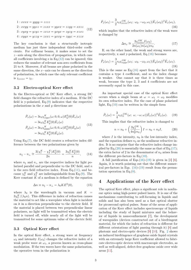
The optical Kerr effect, plays a significant role in nonlin-ear optics using high-power pulsed lasers. It is one of themechanisms contributing to self-focusing in liquids andsolids and has also been used as a fast optical shutterfor picosecond optical pulses. Some of the areas of appli-cation of the Kerr effect includes spectroscopy of liquidsincluding the study of liquid mixtures and the behav-ior of liquids in nanoconfinement [7], the developmentof waveguides (devices constructed out of a birefringentmaterial, for which the index of refraction is different fordifferent orientations of light passing through it) [8] andphotonic and electro-optic devices [9] [10]. Fig. 2 showsan induced birefringence of graphene oxide liquid crystalswith an extremely large Kerr coefficient allowed to fabri-cate electro-optic devices with macroscopic electrodes, aswell as well-aligned, defect-free graphene oxide over wideareas [11].
3
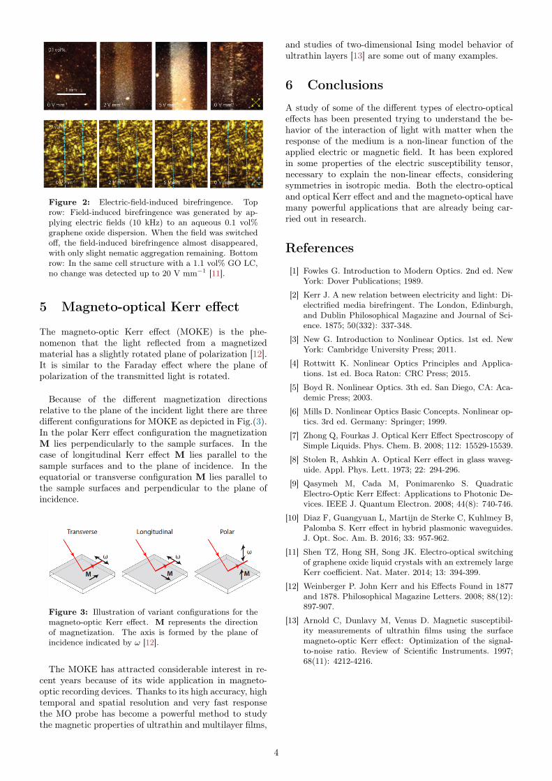
Figure 2: Electric-field-induced birefringence. Toprow: Field-induced birefringence was generated by ap-plying electric fields (10 kHz) to an aqueous 0.1 vol%graphene oxide dispersion. When the field was switchedoff, the field-induced birefringence almost disappeared,with only slight nematic aggregation remaining. Bottomrow: In the same cell structure with a 1.1 vol% GO LC,no change was detected up to 20 V mm−1 [11].
5 Magneto-optical Kerr effect
The magneto-optic Kerr effect (MOKE) is the phe-nomenon that the light reflected from a magnetizedmaterial has a slightly rotated plane of polarization [12].It is similar to the Faraday effect where the plane ofpolarization of the transmitted light is rotated.
Because of the different magnetization directionsrelative to the plane of the incident light there are threedifferent configurations for MOKE as depicted in Fig.(3).In the polar Kerr effect configuration the magnetizationM lies perpendicularly to the sample surfaces. In thecase of longitudinal Kerr effect M lies parallel to thesample surfaces and to the plane of incidence. In theequatorial or transverse configuration M lies parallel tothe sample surfaces and perpendicular to the plane ofincidence.
Figure 3: Illustration of variant configurations for themagneto-optic Kerr effect. M represents the directionof magnetization. The axis is formed by the plane ofincidence indicated by ω [12].
The MOKE has attracted considerable interest in re-cent years because of its wide application in magneto-optic recording devices. Thanks to its high accuracy, hightemporal and spatial resolution and very fast responsethe MO probe has become a powerful method to studythe magnetic properties of ultrathin and multilayer films,
and studies of two-dimensional Ising model behavior ofultrathin layers [13] are some out of many examples.
6 Conclusions
A study of some of the different types of electro-opticaleffects has been presented trying to understand the be-havior of the interaction of light with matter when theresponse of the medium is a non-linear function of theapplied electric or magnetic field. It has been exploredin some properties of the electric susceptibility tensor,necessary to explain the non-linear effects, consideringsymmetries in isotropic media. Both the electro-opticaland optical Kerr effect and and the magneto-optical havemany powerful applications that are already being car-ried out in research.
References
[1] Fowles G. Introduction to Modern Optics. 2nd ed. NewYork: Dover Publications; 1989.
[2] Kerr J. A new relation between electricity and light: Di-electrified media birefringent. The London, Edinburgh,and Dublin Philosophical Magazine and Journal of Sci-ence. 1875; 50(332): 337-348.
[3] New G. Introduction to Nonlinear Optics. 1st ed. NewYork: Cambridge University Press; 2011.
[4] Rottwitt K. Nonlinear Optics Principles and Applica-tions. 1st ed. Boca Raton: CRC Press; 2015.
[5] Boyd R. Nonlinear Optics. 3th ed. San Diego, CA: Aca-demic Press; 2003.
[6] Mills D. Nonlinear Optics Basic Concepts. Nonlinear op-tics. 3rd ed. Germany: Springer; 1999.
[7] Zhong Q, Fourkas J. Optical Kerr Effect Spectroscopy ofSimple Liquids. Phys. Chem. B. 2008; 112: 15529-15539.
[8] Stolen R, Ashkin A. Optical Kerr effect in glass waveg-uide. Appl. Phys. Lett. 1973; 22: 294-296.
[9] Qasymeh M, Cada M, Ponimarenko S. QuadraticElectro-Optic Kerr Effect: Applications to Photonic De-vices. IEEE J. Quantum Electron. 2008; 44(8): 740-746.
[10] Diaz F, Guangyuan L, Martijn de Sterke C, Kuhlmey B,Palomba S. Kerr effect in hybrid plasmonic waveguides.J. Opt. Soc. Am. B. 2016; 33: 957-962.
[11] Shen TZ, Hong SH, Song JK. Electro-optical switchingof graphene oxide liquid crystals with an extremely largeKerr coefficient. Nat. Mater. 2014; 13: 394-399.
[12] Weinberger P. John Kerr and his Effects Found in 1877and 1878. Philosophical Magazine Letters. 2008; 88(12):897-907.
[13] Arnold C, Dunlavy M, Venus D. Magnetic susceptibil-ity measurements of ultrathin films using the surfacemagneto-optic Kerr effect: Optimization of the signal-to-noise ratio. Review of Scientific Instruments. 1997;68(11): 4212-4216.
4