Embed Size (px)
Citation preview

KEMPSVILLE VOLUNTEER RESCUE SQUAD
AMBULANCEDETAILED TECHNICAL REQUIREMENTS
$Revision: 4287 $
Contents
1 Introduction 2
2 Guiding principles 3
3 Applicable documents & intentional abstractions 3
3.1 Government requirements . . . . . . . . . . . . . . . . . . . . . . . . . . . . . 3
3.2 Included documents . . . . . . . . . . . . . . . . . . . . . . . . . . . . . . . . 4
3.3 Intentional abstractions . . . . . . . . . . . . . . . . . . . . . . . . . . . . . . 4
4 Documentation conventions 4
4.1 Doors . . . . . . . . . . . . . . . . . . . . . . . . . . . . . . . . . . . . . . . . 4
4.2 Relative location terminology . . . . . . . . . . . . . . . . . . . . . . . . . . . 4
4.3 Budget priorities . . . . . . . . . . . . . . . . . . . . . . . . . . . . . . . . . . 5
5 SPECIFICATIONS 5
5.1 Safety . . . . . . . . . . . . . . . . . . . . . . . . . . . . . . . . . . . . . . . 5
5.2 Patient care and operations . . . . . . . . . . . . . . . . . . . . . . . . . . . . 7
5.3 Unique identification . . . . . . . . . . . . . . . . . . . . . . . . . . . . . . . . 15
5.4 Traffic signaling . . . . . . . . . . . . . . . . . . . . . . . . . . . . . . . . . . 16
1

6 Illustrations 19
6.1 CPR seat placement . . . . . . . . . . . . . . . . . . . . . . . . . . . . . . . . 19
6.1.1 View from right rear interior corner . . . . . . . . . . . . . . . . . . . . 19
6.1.2 View from side entry door . . . . . . . . . . . . . . . . . . . . . . . . . 20
6.2 Portable oxygen bottle storage . . . . . . . . . . . . . . . . . . . . . . . . . . . 21
6.2.1 Stocked . . . . . . . . . . . . . . . . . . . . . . . . . . . . . . . . . . 21
6.2.2 Empty . . . . . . . . . . . . . . . . . . . . . . . . . . . . . . . . . . . 22
6.3 Backboard compartment . . . . . . . . . . . . . . . . . . . . . . . . . . . . . . 23
6.3.1 Stocked . . . . . . . . . . . . . . . . . . . . . . . . . . . . . . . . . . 23
6.3.2 Empty . . . . . . . . . . . . . . . . . . . . . . . . . . . . . . . . . . . 24
6.4 Stairchair compartment space . . . . . . . . . . . . . . . . . . . . . . . . . . . 25
6.4.1 Stocked . . . . . . . . . . . . . . . . . . . . . . . . . . . . . . . . . . 25
6.4.2 Empty (overview) . . . . . . . . . . . . . . . . . . . . . . . . . . . . . 26
6.4.3 Empty (detail) . . . . . . . . . . . . . . . . . . . . . . . . . . . . . . . 27
6.5 Stairchair bracket . . . . . . . . . . . . . . . . . . . . . . . . . . . . . . . . . 28
6.5.1 Stocked . . . . . . . . . . . . . . . . . . . . . . . . . . . . . . . . . . 28
6.5.2 Empty . . . . . . . . . . . . . . . . . . . . . . . . . . . . . . . . . . . 29
6.6 Electric motor mounting & cage . . . . . . . . . . . . . . . . . . . . . . . . . . 30
6.6.1 Overview . . . . . . . . . . . . . . . . . . . . . . . . . . . . . . . . . . 30
6.6.2 Detail . . . . . . . . . . . . . . . . . . . . . . . . . . . . . . . . . . . 31
6.7 Exterior access to payload module right front cabinet . . . . . . . . . . . . . . . 32
6.8 Shoreline inlet/indicator positioning . . . . . . . . . . . . . . . . . . . . . . . . 33
1 Introduction
In so far as the Kempsville Volunteer Rescue Squad (KVRS) owns or desires one or more am-bulances, there exists a KVRS position derived from the KVRS bylaws called the AmbulanceProcurement & Disposition Coordinator (hereafter, “the Coordinator”). Per the bylaws, TheCoordinator is, among other things, required to:
Develop Detailed Technical Requirements (DTRs) by compiling, at a minimum, the following:
• Federal, state, and local requirements for such apparatus, as provided by the Captain
• Budget requirements provided by the President
• Official Vehicle Uniform requirements adopted by the membership in accordance with theLogos And Uniforms Article in these bylaws
• Special configurations and options, to the extent permitted by the budget

This document, along with the documents it references, helps to fulfill those requirements.
This document should be sufficiently detailed to specify, in a vendor-independent manner, anambulance that reproduces, to the extent possible, what KVRS has owned in the past, plus orminus any changes KVRS desires.
Be mindful that items provided as standard equipment on KVRS’s Wheeled Coach ambulancespurchased between 2008 and 2012 may be assumed in this document to be provided as standardequipment from other vendors. For instance, power door locks and windows in the cab are notenumerated as requirement items because they are now assumed to be standard.
2 Guiding principles
These requirements are derived from the following value system:
• We value meeting all legal requirements.
• We value keeping everyone safe, including crew members, patients, and others.
• We value optimizing patient care and operations.
• We value uniquely identifying ourselves and our units to incident commanders and to thepublic.
• We value signaling our traffic intentions to other drivers.
• We value fiscal responsibility.
3 Applicable documents & intentional abstractions
3.1 Government requirements
The following standards and regulations form a part of this specification, to the extent specifiedor required by law. Unless a specific issue of a standard or regulation is identified, the issue ineffect, on the date the ambulance is contracted for, shall apply:
• Federal Specification for the Star-of-Life Ambulance, KKK-A-1822, U.S. General ServicesAdministration
• Virginia Emergency Medical Services Regulations (12 VAC 5-31)
• City of Virginia Beach Department of EMS Medical Equipment And Supplies Policy
In the event of a conflict between the text of this specification and the references cited above,the text of this specification shall take precedence to the extent feasible.

3.2 Included documents
The standards and requirements contained in the latest version of the following documents arehereby included by reference:
• KVRS Ambulance Graphics Package
• Letters issued to establish official markups to the KVRS Ambulance Graphics Package notyet incorporated into the package itself
3.3 Intentional abstractions
This document intentionally does not, nor should it be modified to, directly contain any specifi-cation of:
• make, model, or class of chassis
• items that depend upon chassis selection or configuration (such as walkthrough doors forType III’s or accordion bellows tube for Type I’s)
• dominant colors or squad-specific graphic elements
The specifications in this document should be equally applicable regardless of the squad’s choiceof these items for a particular purchase order. Rather, the above kinds of specifications shouldbe deferred to subordinate documents or purchase order line items.
4 Documentation conventions
4.1 Doors
When referring to doors in the payload module, the term entry door is used to describe doorsintended for ingress/egress of personnel.
4.2 Relative location terminology
When referring to locations within a compartment, the terms left and right shall mean from theperspective of a person who is facing directly into that compartment. The terms inboard andoutboard shall mean toward or away, respectively, from a line running through the center of thevehicle from its front bumper to its rear bumper.

4.3 Budget priorities
The budget priority column contains values to serve as a guideline when it is not financiallyfeasible to implement this entire set of specifications. In particular:
This indication... ...means the specification is deemed to be...
MAY not important enough to implement if the squad’s other funding prioritieshave not been met
SHOULD important enough to implement if the ambulance procurement budgetallows
MUST so important that it would be better to secure additional funding than tonot implement the specification
5 SPECIFICATIONS
5.1 Safety
# Description Rationale Budgetpriority
5.1.1 Install exterior side mirrors that areremotely adjustable from the driver’sposition.
To optimize visibility adjustments,even when driver-only.
MUST
5.1.2 Install heatable exterior side mirrors. To improve cold weather visibility. MUST5.1.3 Install the most durable valve stems
available.Tire pressure failure attributable tofailure of the valve stem has beenidentified as not uncommon.
MUST
5.1.4 Install most durable available rearentry door hold-open systems at topsof rear entry doors such that doorswill open as far as possible.
To prevent rear doors from swingingin stiff winds and from interferingwith patient loading/unloading. Toprevent premature wear.
MUST
5.1.5 Install brushed aluminum panels oninterior of all payload module entrydoors.
Allows application of reflectivechevrons.
MUST
5.1.6 Install backup alarm without acutoff switch.
Prevents crew from defeating safetymechanism.
MUST
5.1.7 Provide for both rear load lights andthe rearmost side scene lights toactivate when transmission is in“Reverse”.
Increases backing illumination. MUST
5.1.8 Install two white scene lights on eachside of payload module.
Increases scene and backingillumination.
SHOULD
5.1.9 Install two white rear load lights. Increases scene and backingillumination.
SHOULD

# Description Rationale Budgetpriority
5.1.10 Provide for both curb-side scenelights to activate when side payloadmodule entry door is open.
Improves visibility when exiting fromside of payload module.
SHOULD
5.1.11 Provide for rear load lights toactivate when rear entry door isopen.
Improves visibility when exiting fromrear.
MUST
5.1.12 Install stepwell lighting in stepwell. Improves ability to navigate steps indark.
MUST
5.1.13 If mounting stretcher unload hook(desired), mount rear enough toallow stretcher wheels to extend pastflipped-up rear bumper withoutinterference, and mount so as toprevent stretcher from missingunload hook under all conceivableunload situations. Use hook intendedfor stretcher specified by squad.
Stretcher must never be allowed tomiss the unload hook. Theappropriate hook must be used.
MUST
5.1.14 If mounting stretcher unload hook(desired), use a “through-bolting”system to anchor unload hook.
Unload hook must be anchored asstrongly as possible.
MUST
5.1.15 Install Squad Saver Net, 2” straps,black, at head of squad bench,attached with removable latches tofloor, curb-side wall, and overheadliner.
Greater surface area than squadsaver arm rest; and more likely towork when standard vehicle attitudeis upset.
MUST
5.1.16 Provide “airway seat” with integralseat belt and integral child seat.Install so front edge of seat is 99”from closed rear doors when seat ismoved all the way toward the cot.
Assures seat belt will work asengineered. Provides another optionfor transporting small children.Assures seat will be usable for airwaymanagement.
MUST
5.1.17 Use seamless upholstery in thepayload module wherever possible.
Reduces chances of contaminantssurviving decon efforts.
MUST
5.1.18 In interior over rear doors, installbrake/turn indicators slaved todriver’s controls, instead of clock.
Provides payload module occupantssome warning of driver intent.
SHOULD
5.1.19 Install chevrons above and to bothsides of the rear doors. The stripesshould alternate between the squad’sdominant color and reflective white.
Provides visual warning to the rear. MUST

# Description Rationale Budgetpriority
5.1.20 Install chevrons on the lower half ofeach rear entry door, and on thelower half of the payload module sideentry door.
Provides visual warning to the rearwhen the doors are open.
MUST
5.1.21 Install a 12” high 36” wide windowin the payload module curb-side wallover the squad bench.
Provides better visibility of scene tocurb-side.
MAY
5.1.22 Provide a Federal PA300 siren. Extremely simple and intuitiveinterface. All operations can beperformed by touch. Minimizes needto look away from the road.
MUST
5.1.23 Install siren so that horn ring changessiren tones.
Allows driver to keep eyes on theroad and both hands on the steeringwheel.
MUST
5.2 Patient care and operations
# Description Rationale Budgetpriority
5.2.1 Provide a payload module at least170” long.
This is the minimum size adequateto carry the gear that we areaccustomed to carrying. A lengththat also allows designated areas forcarrying crew personal items,including but not limited to turnoutgear, is desireable.
MUST
5.2.2 Install an additional alternator, if afactory option.
The electrical system must becapable of simultaneously poweringall typically attached electricalcomponents, with enough reserve tohandle at least some atypicallyattached electrical components.
MUST
5.2.3 Delete any air microfiltration systemif it takes up otherwise useful space.
We are not satisified that theeffectiveness of these systems hasbeen proven to the extent that itprevents disease transmission orhazmat exposure. We do not havean effective program in place forreplacing microfilters on schedule,hence these systems go to waste.
SHOULD

# Description Rationale Budgetpriority
5.2.4 Install air conditioner for the payloadmodule of the highest capacity andhighest Mean Time To Failure(MTTF) available.
Inadequacy and failure rates of airconditioning in the payload modulehave been frequent irritants.
MUST
5.2.5 Install “CPR seat” so that it will beadjacent to patient’s pelvis/thigharea (not adjacent to a supinepatient’s chest). Delete rearwardcabinets and/or rearward telemetryarea, and extend action area toaccount for this seat placement. (Seeillustration section 6.1.)
No one sits down when doing CPR.Seat needs to be placed to optimizeattendant position for starting an IVon patient’s right hand/arm.Without moving the seat to thisposition, the seat is so far forwardthat the attendant is almost sittingbehind the typical patient’s field ofvision.
MUST
5.2.6 Under “CPR seat” lid, providesufficient storage for 3 “D” sizeoxygen tanks. Install a “W” troughat the bottom of the compartment.Install two quick release straps, tosecure the tanks at the 1/4 and 3/4tank length positions. Tanks are 21”long/high x 4.5” diameter. Must beable to place and remove the tankswithout turning them sideways. (Seeillustration section 6.2.)
Allows for safe interior storage ofadditional portable oxygen.
MUST
5.2.7 Install additional “severe weather”in-wall insulation, if offered.
Assists with temperature control andsound dampening.
SHOULD
5.2.8 Provide an extended cab (but not acrew cab), if available on chassis.
Allows room for radio shop to mountradio/router equipment. May allowdesignated area for carrying crewpersonal items, including but notlimited to turnout gear.
MAY
5.2.9 Provide a 3” drop skirt at outeredges of payload module forward ofrear wheel.
Provides easier ingress & egress.Rampover angle is not a majorconcern in our district.
SHOULD
5.2.10 Provide a double step at side payloadmodule entrance, each step equalheight.
Provides easier ingress & egress. SHOULD
5.2.11 Extend bottoms of compartmentswithin drop-skirt area to bottom ofdrop-skirt.
Provides more room for gear. SHOULD
5.2.12 Provide sweep-out compartmentbottoms where feasible.
Easier to clean. SHOULD

# Description Rationale Budgetpriority
5.2.13 Provide a compartment (IV/DRUGCOMPARTMENT) in the payloadmodule right front cabinet thatreaches ceiling level and that isdimensioned to hold at least oneTEMS IV Box and one TEMS DrugBox, lockable with a standardpadlock. Assume both TEMS boxesare 19” deep 10.75” high 11.5” wide.This compartment is only to beaccessible from the interior.
City requirement: “All IV and drugboxes will be stored in lockedcompartments or brackets when notin use. Compartment design must beapproved by the Department and theVirginia Department of Health Officeof EMS. A standard lock shall beused for all rescue squad,Department of EMS, and FireDepartment operated vehicles.”
MUST
5.2.14 Provide a 100% height external rightrearmost compartment(BACKBOARD COMPARTMENT).In this compartment, install a 3/16”thich 14” deep vertical divider 8.25”from right wall. Install a shelfforward of aforementioned verticaldivider halfway between ceiling andfloor, mounted on 20” of adjustableshelf track (10” of track above andbelow shelf). Install a seat beltacross entire compartment opening,30” down from ceiling, 2” fromcompartment opening, secured withzinc footman loops. (See illustrationsection 6.3.)
Allows orderly stowage of backboardsand scoop stretcher, velcro splintpack, and C-collar pack. Strap helpsprevent gear from falling ontopersonnel.
MUST

# Description Rationale Budgetpriority
5.2.15 Provide a 3/4 height external leftrearmost compartment (STAIRCHAIR COMPARTMENT).Approximately 40” from floor, makethis compartment accessible frominterior as well. In the lowerapproximately 40” of thiscompartment, install two adjustable3/16” thick 40” tall 7.5” deepvertical dividers on shelf trackmounted to and running the width ofthe inboard wall, to divide theinboard section of the compartmentinto thirds. Install a seat belt on theleft and right walls, 8” from theinboard wall, secured with zincfootman loops. In theinterior-accessible upper portion ofthis compartment, install adjustableshelf track and two shelves. (Seeillustration section 6.4.)
Allows orderly stowage of tractionsplints and KEDs, andinterior/exterior access to otheritems. Seat belts help prevent gearfrom falling into personnel.
MUST
5.2.16 Reinforce door/hinge of STAIRCHAIR COMPARTMENT. Oninterior of this door, near the bottom,mount a box sufficient to carry a37.5” high 20.5” wide 8” deep heavyduty (Stryker 6252) stair chair.Reinforce the box with additionalscrews or rivets. Install a horizontalseat belt, secured with zinc footmanloops, approximately 30” abovebottom of stair chair box sufficientto secure top portion of stair chair.(See illustration section 6.5.)
Allows orderly stowage of stair chairand uses door rather than muscle toshift stair chair away fromcompartment interior.
MUST
5.2.17 Provide a 3/4 height external leftforwardmost compartment (MAINOXYGEN COMPARTMENT). Theupper portion of this compartmentmust be accessible via a lexan doorto the interior action area.
To carry main oxygen and portablelantern. Provides interior access tomain O2 valve.
MUST

# Description Rationale Budgetpriority
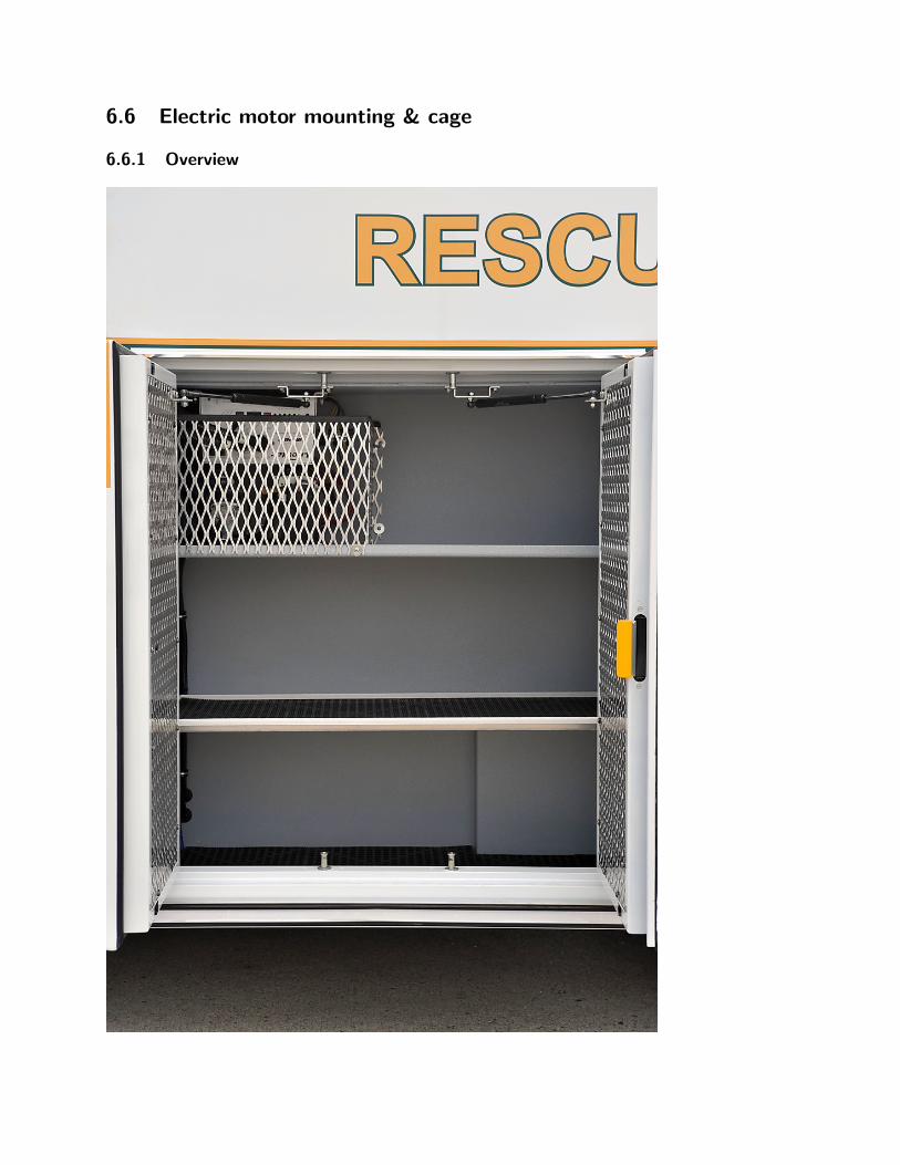
5.2.18 Provide a 1/2 height external leftcompartment immediately behind theMAIN OXYGEN COMPARTMENT.In this compartment, mount inverteron ceiling, close to forward wall.Install a fixed shelf sufficiently belowthe inverter to allow the following:Mount airhorn pump and vacuumpumps to the fixed shelf so they willsit immediately below the inverter.Install a single heat isolation cagearound the area occupied by theinverter, airhorn pump, and vacuumpump. (See illustration section 6.6.)
Allows space-efficient mounting ofinverter, airhorn pump, and vacuumpump.
MUST
5.2.19 Apply privacy tinting to all payloadmodule windows.
Patient privacy and climate control. MUST
5.2.20 Install a grab bar inside the sidepayload module entry.
To allow a person to steady selfusing left hand while enteringpayload module.
SHOULD
5.2.21 Install an exterior stealth failsafeswitch in passenger side grill tounlock payload module doors.
To prevent lock-outs. MUST
5.2.22 Provide gas strut hold-open for sidepayload module door.
We’ve been dissatisfied with springhold-opens.
MUST
5.2.23 Provide for compartment doors toopen 135 degrees unless doing soallows compartment door to impacttravel of another door at any point.
Allows easier access to gear. SHOULD
5.2.24 Upgrade incandescent lighting toLED wherever possible.
Reduces electrical load andburn-outs.
MUST
5.2.25 Provide for payload module mainpower bus to be slaved to OEMignition switch.
Allows more intuitive control ofpayload module power.
MUST
5.2.26 Provide 5 minutes of electrical powerto payload module (but not topayload module air conditionerblower) when ignition is switched off.Provide dual-action momentaryrocker switch on driver’s side of cabconsole to (a) force timer to expire,and (b) reactivate timer.
Prevents sudden darkness frominterfering with patient care andegress. Allows driver to conservebattery when timer is not needed.Allows driver to recover frominadvertent interference with timerfunction.
MUST

# Description Rationale Budgetpriority
5.2.27 Install one extra 12V automotivebattery, wired in parallel, in payloadmodule battery compartment.
Reduces electrical failures. SHOULD
5.2.28 Provide 5 antenna ports in payloadmodule roof. {CONFIRM}
For standard complement of radios &MDT equipment.
MUST
5.2.29 Provide 5 RG58/U coax cables with6 ft pigtails. Run cables from roofports 1 and 2 to cab console. Runcables from roof ports 3, 4, and 5 topayload module action area.{CONFIRM}
For standard complement of radios &MDT equipment.
MUST
5.2.30 Provide a door for exterior access tothe non-lockable portion of thepayload module’s right front cabinet.(See illustration section 6.7.)
For efficient outside access toportable equipment.
MUST
5.2.31 Provide 2 cigar lighter outlets, on 20amp circuit, energized by ignition &shoreline, in payload module asfollows: One on wall in action areaadjacent to “airway seat”, the otheron wall in extended action area justforward of “CPR seat”.
To power squad and personal gear. SHOULD
5.2.32 Provide a cigar lighter outlet, on 20AMP circuit, energized by ignition &shoreline, in payload module asfollows: In right front cabinet, in theuppermost portion that is accessiblefrom the interior and the exterior.
To charge portable gear. MUST
5.2.33 Provide a 12VDC 15 amp powersource (hot and ground) on ignitioncircuit w/6 ft pigtail, terminatingbehind the action area wall.
To power gear. MUST
5.2.34 Provide a 12VDC 15 amp powersource (hot and ground) on batterycircuit w/6 ft pigtail, terminating inthe front cab console.
To power gear. MUST
5.2.35 Provide a 12VDC 30 amp powersource (hot and ground) on batterycircuit w/6 ft pigtail, terminatingbehind the passenger seat.
To power gear. MUST

# Description Rationale Budgetpriority
5.2.36 Install auto-eject shoreline inlet, withinterrupter, with white cover, ondriver’s side of payload module justforward of forewardmostcompartment at approximately eyelevel. Install a green LED 110VACshoreline indicator light just above.(See illustration section 6.8.)
To make the shoreline easilyaccessible to the driver as driver getsin/out of driver’s seat, and toindicate whether circuit issuccessfully energized. Interrupterprevents sparking if under load whenejected.
MUST
5.2.37 Provide 2 dual-socket 110VACoutlets in payload module as follows:One on wall in action area adjacentto “airway seat”, the other on wall inextended action area just forward of“CPR seat”.
To power gear. MUST
5.2.38 Provide a dual-socket 110VAC outletin payload module as follows: Inright front cabinet, in the uppermostportion that is accessible from theinterior and the exterior.
To power gear. MUST
5.2.39 Rig inverter to be “always on”.Delete action area inverter switch.
Required by our standardcomplement of I.T. gear.
MUST
5.2.40 Install engine block heater, withswitch behind driver’s seat, wired toshoreline.
Extends engine life. SHOULD
5.2.41 Use 1050W inverter/charger topower all 110VAC receptacles,“charger 20 amp automaticw/integral cut off”.
To power and charge gearappropriately.
MUST
5.2.42 Provide “Miami-Dade” front cabconsole (or similar).
Has room for our standardcomplement of radio heads. Allowsorderly stowage of more gear. Hascup-holders.
MUST
5.2.43 Replace OEM cab domelight withdomelight that can be switched toeither white or red, wired to ignition,with switches on dome light itself.
Allows interior lighting with lessimpact on driver vision, and intuitiveactivation.
SHOULD
5.2.44 If using CoolBar or equivalent withangled faces, install additional whitescene light on lower half of eachangled face, to come on withsame-side standard scene lights.
Extends scene lighting to area moreforward than standard.
MAY

# Description Rationale Budgetpriority
5.2.45 On payload module interior ceiling,install white lights, with appropriateswitches in action area, as follows: 4dual-intensity on curb side; 3dual-intensity on street side; 3flourescent recessed approximately oncenter line.
Increases illumination options forpatient care.
MUST
5.2.46 Install a 5” (or so) light undercabinetry to illuminate action areaonly, with integral switch.
Allows limited lighting for attendantwithout necessarily lighting patient.
MAY
5.2.47 Install 400,000 or greatercandlepower spotlight in front cab,wired from passenger side.
Encourages use by passenger ratherthan driver. If not stowed properly,cord will not foul driver’s pedal area.
MUST
5.2.48 Install 15-minute timer switch onbattery circuit on curb-side wall atfront of squad bench, to allowactivation & deactivation of interioroverhead flourescent lights only.
To better control lighting. MUST
5.2.49 Install small light in circuit boardcompartment, with integral switch,on constant hot circuit.
To assist with electricaltroubleshooting.
SHOULD
5.2.50 Install aproximately full-lengthoverhead grab rail in payload module.
To assist with steadying personnel. MUST
5.2.51 Install high-durability grab rails onpayload module door interiors.
To assist with entering/exitingpayload module.
MUST
5.2.52 Install rack for M or H oxygencylinder in MAIN OXYGENCOMPARTMENT, on right wall asclose to inboard wall as possible,allowing hand access to 3ratchet-style straps.
Our oxygen replenishment systemnegates need to remove/replaceoxygen cylinders.
MUST
5.2.53 Install Ohio-style oxygen/suctionports as follows: 2 O2 outlets and 1vacuum port in action area; 1 O2outlet on curb-side wall at head ofsquad bench.
Provides for airway & oxygenation ofhigh acuity patient on cot, while alsoproviding for oxygenation of loweracuity patient on squad bench.
MUST
5.2.54 Install Stryker 6377 cot mounts inthe center position only, not in thestreet-side wall position. Installforward fastener 87-1/4” from closedrear doors, measured to center of themost forward cot plate bolt.
We never use the other position. MUST

# Description Rationale Budgetpriority
5.2.55 Provide IV hooks only as follows:Perko style or equivalent, just belowceiling; w/velcro straps positioned toprevent IV bags from swinging; 1 oncurb-side at front of squad bench; 1on curb-side roughly midway downsquad bench; 1 on street side justforward of “CPR seat”; 1 on streetside just rear of “CPR seat”.
Unobtrusive, convenient, andproximity to walls helps preventswinging even if straps aren’t utilized.
MUST
5.2.56 Install tethered oxygen wrench inMAIN OXYGEN COMPARTMENT.
MUST
5.2.57 Use lexan interior compartment doorsto the extent possible.
Allows attendants to see contents ofcompartment without having to opencompartment.
SHOULD
5.2.58 In payload module right frontcabinet, if any interior compartmentdoors open to the side, make surethe handle is on the left and thehinge is on the right.
Experience shows that access ishindered if doors open in otherdirection.
MUST
5.2.59 Provide a squad bench with a split50/50 lid.
Allows access to gear under lid(s)even if gear or people are occupyingone lid and can not be easily moved.
MUST
5.2.60 Provide gas strut (at least 30 LBcapacity) hold-opens for squad benchlids.
Prevents lids from inadvertentlyfalling and scraping/pinchingpersonnel.
MUST
5.2.61 Use rivets to secure front & rearkickplates/stoneguards to body.
Our experience is that screws tend toback out.
MUST
5.2.62 Install dri-deck, turtletile, orequivalent, at bottom of all exteriorcompartments and shelves.
Allows rain to drip below gear. SHOULD
5.3 Unique identification
# Description Rationale Budgetpriority
# Description Rationale Budgetpriority
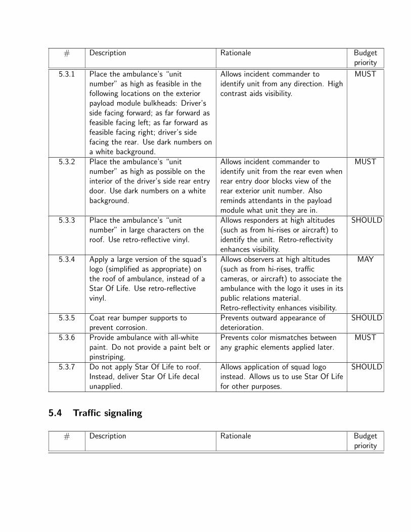
5.3.1 Place the ambulance’s “unitnumber” as high as feasible in thefollowing locations on the exteriorpayload module bulkheads: Driver’sside facing forward; as far forward asfeasible facing left; as far forward asfeasible facing right; driver’s sidefacing the rear. Use dark numbers ona white background.
Allows incident commander toidentify unit from any direction. Highcontrast aids visibility.
MUST
5.3.2 Place the ambulance’s “unitnumber” as high as possible on theinterior of the driver’s side rear entrydoor. Use dark numbers on a whitebackground.
Allows incident commander toidentify unit from the rear even whenrear entry door blocks view of therear exterior unit number. Alsoreminds attendants in the payloadmodule what unit they are in.
MUST
5.3.3 Place the ambulance’s “unitnumber” in large characters on theroof. Use retro-reflective vinyl.
Allows responders at high altitudes(such as from hi-rises or aircraft) toidentify the unit. Retro-reflectivityenhances visibility.
SHOULD
5.3.4 Apply a large version of the squad’slogo (simplified as appropriate) onthe roof of ambulance, instead of aStar Of Life. Use retro-reflectivevinyl.
Allows observers at high altitudes(such as from hi-rises, trafficcameras, or aircraft) to associate theambulance with the logo it uses in itspublic relations material.Retro-reflectivity enhances visibility.
MAY
5.3.5 Coat rear bumper supports toprevent corrosion.
Prevents outward appearance ofdeterioration.
SHOULD
5.3.6 Provide ambulance with all-whitepaint. Do not provide a paint belt orpinstriping.
Prevents color mismatches betweenany graphic elements applied later.
MUST
5.3.7 Do not apply Star Of Life to roof.Instead, deliver Star Of Life decalunapplied.
Allows application of squad logoinstead. Allows us to use Star Of Lifefor other purposes.
SHOULD
5.4 Traffic signaling
# Description Rationale Budgetpriority

# Description Rationale Budgetpriority
5.4.1 Install LED OptiCom (w/infraredfilter if available) as high andcentered as is feasible. If dimensionsallow, install it flush with frontbulkhead (or CoolBar) behind clearlens. Wire OptiCom to transmission“Drive” gear only.
To control traffic signals. Infraredfilter prevents other drivers fromgetting confused when OptiCom isused during routine transports. Flushmounting improves aesthetics.OptiCom should not be on when unitis not in Drive.
MUST
5.4.2 Provide ambulance warning lightsequencer & load manager system,with switches on console.
Manages load on electrical system. MUST
5.4.3 Wire siren to be sequencer-hot only. Prevents operation of siren withoutwarning lights.
MUST
5.4.4 Provide airhorns. For better warning to other drivers insound-insulated vehicles.
MAY
5.4.5 Install airhorn activation valvew/lanyard, located in center ofheadliner.
Makes activating airhorn moreintuitive.
MAY
5.4.6 Install 2 red ambulance warning lightson rear to be visible through windowswhen rear doors are opened, to beactivated in “primary” mode only.
Provides additional signalingprotection to rear, not masked byopen doors.
SHOULD
5.4.7 Install 2 red ambulance warninglights inboard of mandated cornerred lights at top front of payloadmodule, to be activated in “primary”mode only.
Provides additional signaling to cleartraffic ahead.
MAY
5.4.8 Install an amber ambulance warninglight at top center rear, to alternatewith mandated corner red lights, tobe activated in “primary” mode only.
Provides additional signalingprotection to rear.
MAY
5.4.9 Install a red ambulance warning lightabove and forward of each frontwheel as front intersection lights, tobe activated in “primary” and“secondary” modes.
Provides forward signaling to crossingtraffic as nose enters lane, and toadjacent-lane traffic. Should never bedefeatable due to high risk exposurewhen entering crossing lane.
MUST
5.4.10 Install 2 red ambulance warninglights as grill lights, to be activatedin “primary” and “secondary” modes.
Provides forward signaling to cleartraffic immediately ahead (that maynot have visibility to higher lights).
MAY

# Description Rationale Budgetpriority
5.4.11 If using CoolBar or equivalent withangled faces, install additional redambulance warning light on upperhalf of each angled face, to beactivated in “primary” mode only.
Provides additional signaling to frontand sides.
MAY
5.4.12 Install a red ambulance warning lightjust over each rear wheel, to beactivated in “primary” mode only.
Provides additional signaling tocrossing and adjacent-lane traffic.
MAY
5.4.13 Install “wig-wag” headlight flashersystem, to activate in accordancewith VA state law.
Provides additional signaling to cleartraffic ahead.
MAY
5.4.14 Install additional amber arrow turnsignals, one each under frontmandated corner red lights, slaved toOEM turn signals.
Provides additional signaling ofintent to turn or change lanes totraffic ahead that may not havevisibility to lower OEM turn signals.
MAY
5.4.15 Upgrade incandescent lights to LED(or better) wherever possible.
Reduces electrical load andburn-outs.
MUST
5.4.16 Use clear lenses on ambulancewarning lights to the extent possible.
Improves aesthetics. MAY
5.4.17 Use chrome-plated flanges aroundambulance warning lights to theextent possible.
Improves aesthetics. MAY

6 Illustrations
6.1 CPR seat placement
6.1.1 View from right rear interior corner

6.1.2 View from side entry door

6.2 Portable oxygen bottle storage
6.2.1 Stocked

6.2.2 Empty

6.3 Backboard compartment
6.3.1 Stocked

6.3.2 Empty

6.4 Stairchair compartment space
6.4.1 Stocked

6.4.2 Empty (overview)

6.4.3 Empty (detail)

6.5 Stairchair bracket
6.5.1 Stocked

6.5.2 Empty
6.6 Electric motor mounting & cage
6.6.1 Overview

6.6.2 Detail

6.7 Exterior access to payload module right front cabinet

6.8 Shoreline inlet/indicator positioning