Embed Size (px)
Citation preview

2
Contents
Safety Information 3
General operation 5 Transport 5 Hydraulics 5 Maintenance and inspection 5
Section 1 Warranty 7
Thank you for choosing a Kelly Tillage product 7 Warranty policy 8 Product registration form 9
Section 2 Machine Operation 11
Before operation 11 Pre-operation checklist 11
Section 3 Chain Operation & Correct Setup 13
Importance of chain tension 13 Chain tension 13 Chain curve 15 Chain mount arm height adjustment 16 Frame height adjustment 17
Section 4 Maintenance & Inspection 19
Maintenance and inspection 19 Recommended maintenance checklist 20 Chain inspection 21 Trouble shooting 21
Section 5 Specifications 23
Operating speeds 23 Tire pressure 23 12X specifications 23 Bolt torque settings 24 Disc chain lengths and quantities 25
Section 6 Pre-Delivery Checklist 28
Pre-delivery checklist 28 Notes 29

3
SAFETY INFORMATION
Read all operating instructions and study all photographs thoroughly before operating the unit.
Please note: Left and right is determined by standing behind the machine and looking to the front.
4
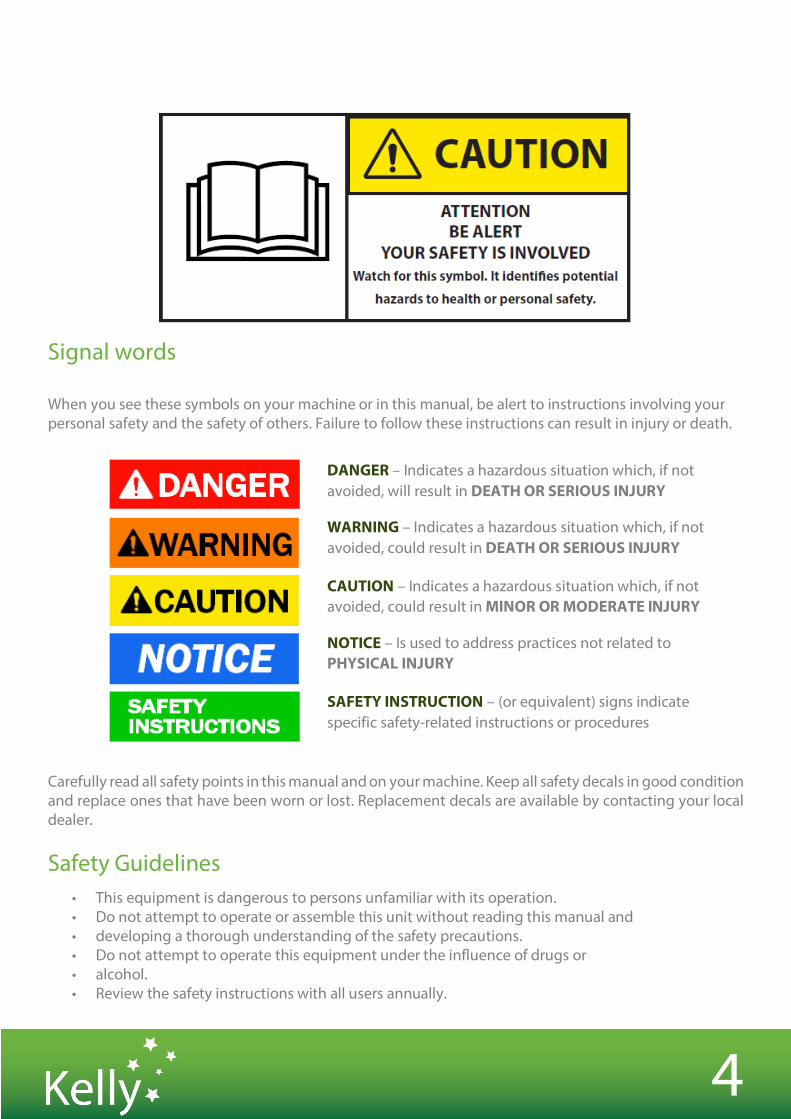
Signal words When you see these symbols on your machine or in this manual, be alert to instructions involving your personal safety and the safety of others. Failure to follow these instructions can result in injury or death.
Carefully read all safety points in this manual and on your machine. Keep all safety decals in good condition and replace ones that have been worn or lost. Replacement decals are available by contacting your local dealer.
Safety Guidelines • This equipment is dangerous to persons unfamiliar with its operation. • Do not attempt to operate or assemble this unit without reading this manual and • developing a thorough understanding of the safety precautions. • Do not attempt to operate this equipment under the influence of drugs or • alcohol. • Review the safety instructions with all users annually.
DANGER – Indicates a hazardous situation which, if not avoided, will result in DEATH OR SERIOUS INJURY
WARNING – Indicates a hazardous situation which, if not avoided, could result in DEATH OR SERIOUS INJURY
CAUTION – Indicates a hazardous situation which, if not avoided, could result in MINOR OR MODERATE INJURY
NOTICE – Is used to address practices not related to PHYSICAL INJURY
SAFETY INSTRUCTION – (or equivalent) signs indicate specific safety-related instructions or procedures
5
General operation • Proceed cautiously under overhead powerlines and around power poles - contact may result in the
operator suffering a severe electrical shock. • Never allow anyone within the immediate area when operating machinery. • Stand clear of frame when it is being raised or lowered.
Transport • Always travel at a safe speed. NEVER EXCEED 25kph/16 mph. • Ensure your speed is low enough for an emergency stop to be safe and secure and reduce speed
prior to turns. • Ensure safety chain is attached correctly to the towing vehicle. • Please refer to your own country, state, provincial, county or municipality laws on the rules of
transporting farm machinery on roads. • Chains should be clear of the ground. • Beware of obstacles and overhead powerlines. • Use approved accessories and necessary warning devices at all times when transporting on the
road.
Hydraulics • NEVER remove hydraulic hoses or ends unless the machine is in either transport position or fully
extended in working position. Relieve all hydraulic pressure before disconnecting hydraulic hoses and fittings.
• Ensure all fittings and hoses are in good condition. • Wear appropriate face and hand protection or PPE when checking hydraulics under pressure to
avoid injury. • Double check that all is clear before operating hydraulics. • Maintain proper hydraulic fluid levels and pressure.
Maintenance and Inspection • Good maintenance is your responsibility. • Regular maintenance and inspection are imperative.
Maintenance guidelines can be found in Section 4
If any safety decals are missing, please contact your local dealer immediately and do not use the machine

WARRANTY SECTION 1

7
SECTION 1 WARRANTY
Thank you for choosing a Kelly Tillage product
We trust that you find the following manual clear and easy to follow. If you should require additional customer support or assistance, please do not hesitate to contact us.
Spare parts can be purchased, as required, through your local dealer or by contacting the Kelly team directly.
Kelly welcomes feedback. Should you have any difficulties that you wish to raise, suggestions for improvement or modifications that you feel would enhance our products we look forward to hearing from you.
Contact Information
Australia Kelly Engineering PO Box 100 Booleroo Centre SA 5482 Phone: + 61 8 8667 2253 Email: [email protected] Spare Parts: [email protected] Website: www.kellytillage.com United States – Spare parts Hood & Company Inc Springfield MO Phone: +1 417 865 2100 Email: [email protected] Canada – Spare parts Adair Sales & Marketing Company Inc Swift Current SK Phone: +1 306 773 0996 Email: [email protected]
8
Warranty Policy
Kelly guarantees its products against faulty workmanship and materials for twelve (12) months from date of purchase. Disc Chain, Prickle Chain and Swivel Bearing units are considered to be wear items and it’s reasonable to expect that these parts may need to be replaced over time. We do however guarantee the Swivel Bearing units for a period of twelve (12) months or 10,000 acres, whichever occurs first.
Ground engaging tools are warranted against faulty material and workmanship for 50 000 acres. Replaceable cutting disc blades are warranted against faulty materials and workmanship only. All other ground tools carry a 50 000 acre wear warranty.
Kelly is offering an additional 12 month warranty if the machine is registered within 2 months of purchasing the machine. Machine registrations can be completed by the customer or dealer on the Kelly website or by the warranty registration form in the operator manual.
Kelly’s warranty policy does not cover misuse, modifications, damage during transit or product that has not been maintained per the Kelly maintenance procedures outlined in the relevant product manual. Failure to properly maintain the machine or blatant misuse shall result in the warranty being null and void.
The warranty for the machine will be voided immediately if any non-Kelly OEM (Kelly original equipment manufacturer) part is used on the machine.
Kelly reserves the right to request written, photographic, or video documentation prior to any warranty authorisation. All warranty queries and requests for authorisation can be directed to [email protected].
Any warranty repair, service or modification to products must be pre-approved by Kelly in writing and performed by an authorised Kelly dealer. If there are service parts needed this must be ordered through Kelly parts distribution and Kelly will issue a Returned Goods Authorization (RGA) for any faulty parts that are to be returned.
To ensure the continuity of warranty, related to any approved claims, it is expected that all warranty repair works are completed in a timely fashion, as specified by Kelly.
Any claim for warranty, labour or parts must be completed on the Kelly website.
Warranty claims are to be lodged within 30 days of completion of work. If further information is requested on the claim from the Market Liaison Officer, you have 30 days to provide the information. If you fail to apply with the above instructions the warranty claim will be declined and closed.
Upon completion and approval of this claim the dealer will receive a credit to their account.

9
Product registration form
On a scale of 1 to 10 (10 being highest) how likely are you to recommend us to friends and family ?
1 2 3 4 5 6 7 8 9 10
If you scored 8 or below then what must we do to become a 10 in your opinion?
If you scored 9 or above then please tell us why you gave us this score?
Satisfaction with dealer/ agent
• Was the machine delivered satisfactorily?• Were dealers well informed about the product? • Would you recommend the dealer to other farmers?
Yes Yes Yes
No, why not?______________ No, why not?______________ No, why not?______________
Occupation
Farmer Customer Operator _______________ Other ________________________________
What brought Kelly Tillage products to your attention?
Dealer Field day Demostration
Radio Local Dealer Family Friends/neighbour
Website
Other_______________________
Magazine/newspaper ________________
Purchasing Details Purchaser/ owner
If your machine is REGISTERED
within 2 months of purchasing the machine will receive an additional 12 months warranty.
COMPLETE and
RETURN
your form online, by email or post to Kelly in order to
receive the additional 12 months warranty.
Complete online Mail to
Email http:/www.kellytillage.com/machine-registration Kelly Engineering
PO Box 100 Booleroo Centre SA 5482 Australia [email protected]
Name___________________________________ Address_________________________________ Email Address____________________________ Contact number__________________________
Place of Purchase___________________________ Date of Purchase___________________________ Model Purchase____________________________ Serial number______________________________
_____________________________________________________________________________________________________________________________________________________________________________________ _____________________________________________________________________________________________________________________________________________________________________________________
6
MACHINE OPERATION SECTION 2
11
SECTION 2 MACHINE OPERATION
Before operation
• Carefully study and understand this manual. • Do not wear loose fitting clothing that may catch in moving parts. • Always wear protective clothing and footwear. • Be sure that there are no tools lying in or on the equipment. • Do not use the machine until you are sure that the area is clear, particularly of children or animals. • If this machine is being used in a dry area, or in the presence of combustibles, care should be taken
to prevent fires and firefighting equipment should be readily available. • Familiarise yourself and other operators with the machine’s operation before using.
Pre-operation Checklist
Check Item: Done 1. All wheel nuts, bolts and nuts are tightened to the correct torque setting 2. Split pins are in place 3. Stickers and warning signs are in place 4. Hydraulic fittings are tight and have no leaks 5. Chains are adjusted so that all springs are compressed to 330mm/ 1’ 1” 6. Check swivel bearings are not seized and still turning freely

CHAIN OPERATION SECTION 3
13
SECTION 3 CHAIN OPERATION & CORRECT SETUP
Importance of Chain Tension
Operational It is imperative that the correct adjustment be maintained. Only through correct adjustment can a smooth and level finish be achieved in field working. Loose chains lead to:
• Uneven performance across the width of the machine • Uneven weed control • Unsatisfactory incorporation • Ineffective levelling • Accelerated or premature chain wear • Uneven field surface with ridges and furrows being created.
The leading 1/3rd of a loose chain is much more aggressive than the trailing 1/3rd and the centre. This will mean that the middle of the machine’s front pair of chains will aggressively move soil outwards. The machine’s rear pair of chains, if loose, have their aggressive 1/3rd near the wing extremity. It follows then that as the front discs push soil outwards, the least aggressive portion of the rear chain follows them and does not balance the soil movement. This is exacerbated at the wings, effectively creating a broad ridge about halfway out each wing. It will not be evident in one pass but is possible if care is not taken over time.
A correctly adjusted machine will not have this problem.
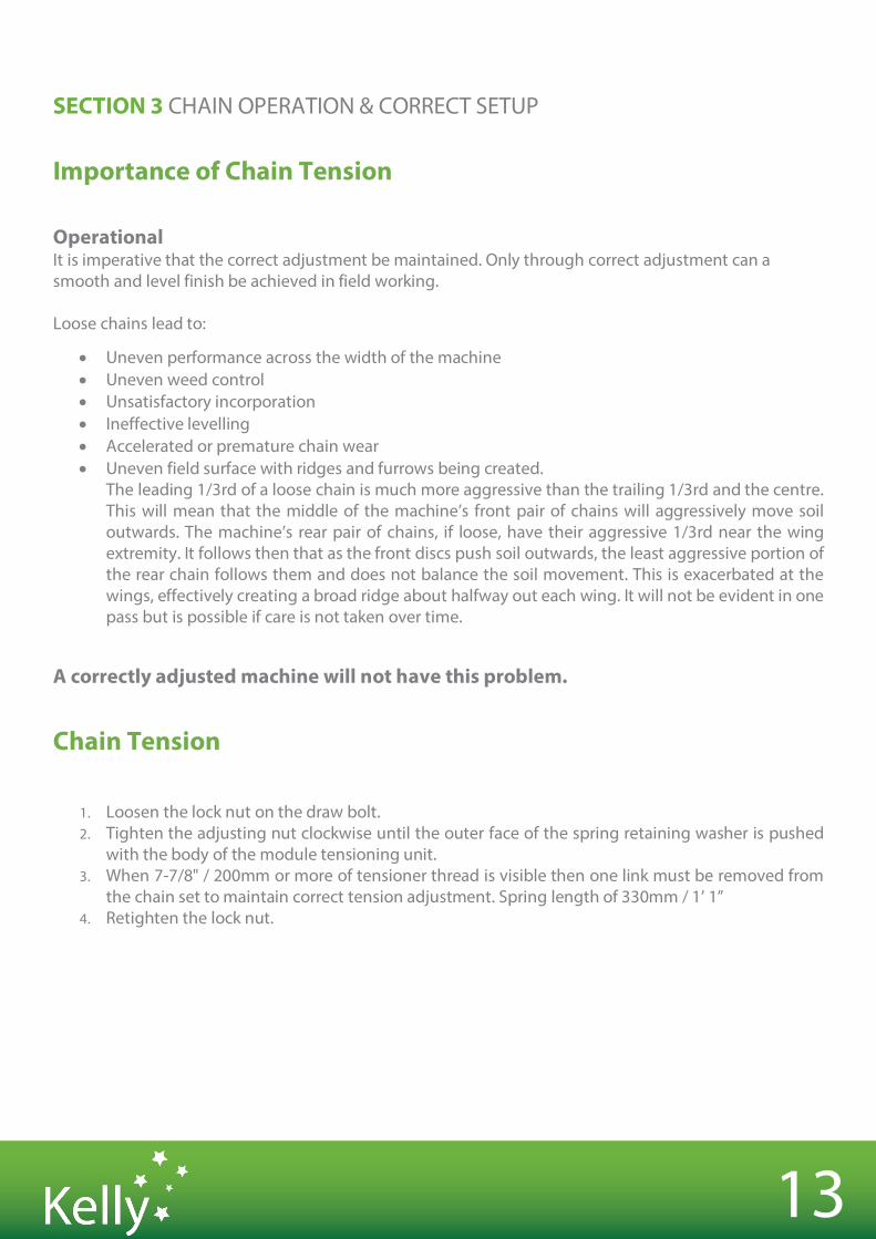
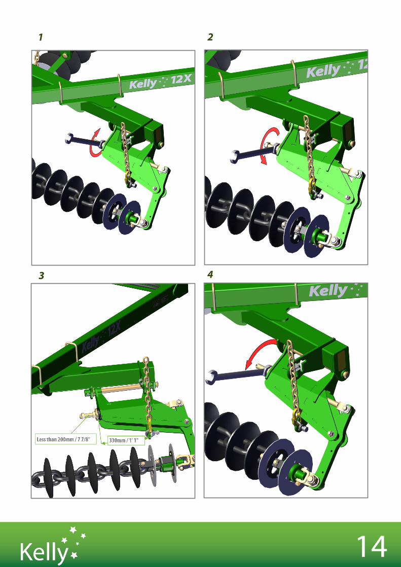
Chain Tension
1. Loosen the lock nut on the draw bolt. 2. Tighten the adjusting nut clockwise until the outer face of the spring retaining washer is pushed
with the body of the module tensioning unit. 3. When 7-7/8" / 200mm or more of tensioner thread is visible then one link must be removed from
the chain set to maintain correct tension adjustment. Spring length of 330mm / 1’ 1” 4. Retighten the lock nut.
14
1 2
3 4
15
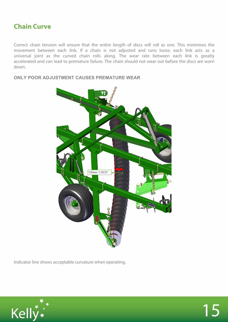
Chain Curve
Correct chain tension will ensure that the entire length of discs will roll as one. This minimises the movement between each link. If a chain is not adjusted and runs loose, each link acts as a universal joint as the curved chain rolls along. The wear rate between each link is greatly accelerated and can lead to premature failure. The chain should not wear out before the discs are worn down.
ONLY POOR ADJUSTMENT CAUSES PREMATURE WEAR
Indicator line shows acceptable curvature when operating.
16
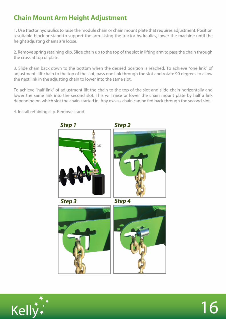
Chain Mount Arm Height Adjustment
1. Use tractor hydraulics to raise the module chain or chain mount plate that requires adjustment. Position a suitable block or stand to support the arm. Using the tractor hydraulics, lower the machine until the height adjusting chains are loose.
2. Remove spring retaining clip. Slide chain up to the top of the slot in lifting arm to pass the chain through the cross at top of plate.
3. Slide chain back down to the bottom when the desired position is reached. To achieve “one link” of adjustment, lift chain to the top of the slot, pass one link through the slot and rotate 90 degrees to allow the next link in the adjusting chain to lower into the same slot.
To achieve “half link” of adjustment lift the chain to the top of the slot and slide chain horizontally and lower the same link into the second slot. This will raise or lower the chain mount plate by half a link depending on which slot the chain started in. Any excess chain can be fed back through the second slot.
4. Install retaining clip. Remove stand.
Step 1 Step 2
Step 3 Step 4
17
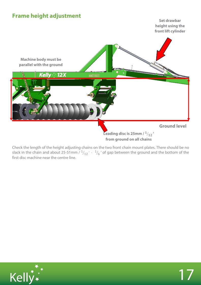
Frame height adjustment
Check the length of the height adjusting chains on the two front chain mount plates. There should be no slack in the chain and about 25-51mm / 1 12# ‘ - 1 6# ‘ of gap between the ground and the bottom of the first disc machine near the centre line.
Ground level
Set drawbar height using the front lift cylinder
Leading disc is 25mm / 𝟏 𝟏𝟐# ‘ from ground on all chains
Machine body must be parallel with the ground
MAINTENANCE & INSPECTION
SECTION 4
19
SECTION 4 MAINTENANCE & INSPECTION
Maintenance and Inspection Good maintenance is your responsibility
• Before working on your machine, ensure all moving parts have stopped • Always use a safety support and block the wheels • Use extreme caution when making adjustments • Replace shields and guards after servicing and before moving • After servicing, make sure all tools, parts and service equipment are removed • Where replacement parts are necessary for periodic maintenance and servicing, genuine factory
parts must be used. Kelly will not guarantee the use of unapproved parts and other damages as a result of their use and will not be liable for injury or warranty if equipment has been altered in any way
• An appropriate fire extinguisher and first aid kit should be kept readily available while performing maintenance.
20
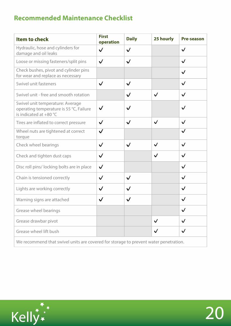
Recommended Maintenance Checklist
Item to check First operation
Daily 25 hourly Pre-season
Hydraulic, hose and cylinders for damage and oil leaks
✔ ✔ ✔
Loose or missing fasteners/split pins ✔ ✔ ✔
Check bushes, pivot and cylinder pins for wear and replace as necessary
✔
Swivel unit fasteners ✔ ✔ ✔
Swivel unit - free and smooth rotation ✔ ✔ ✔
Swivel unit temperature: Average operating temperature is 55 °C, Failure is indicated at +80 °C
✔ ✔ ✔
Tires are inflated to correct pressure ✔ ✔ ✔ ✔
Wheel nuts are tightened at correct torque
✔ ✔
Check wheel bearings ✔ ✔ ✔ ✔
Check and tighten dust caps ✔ ✔ ✔
Disc roll pins/ locking bolts are in place ✔ ✔
Chain is tensioned correctly ✔ ✔ ✔
Lights are working correctly ✔ ✔ ✔
Warning signs are attached ✔ ✔ ✔
Grease wheel bearings ✔
Grease drawbar pivot ✔ ✔
Grease wheel lift bush ✔ ✔
We recommend that swivel units are covered for storage to prevent water penetration.
21
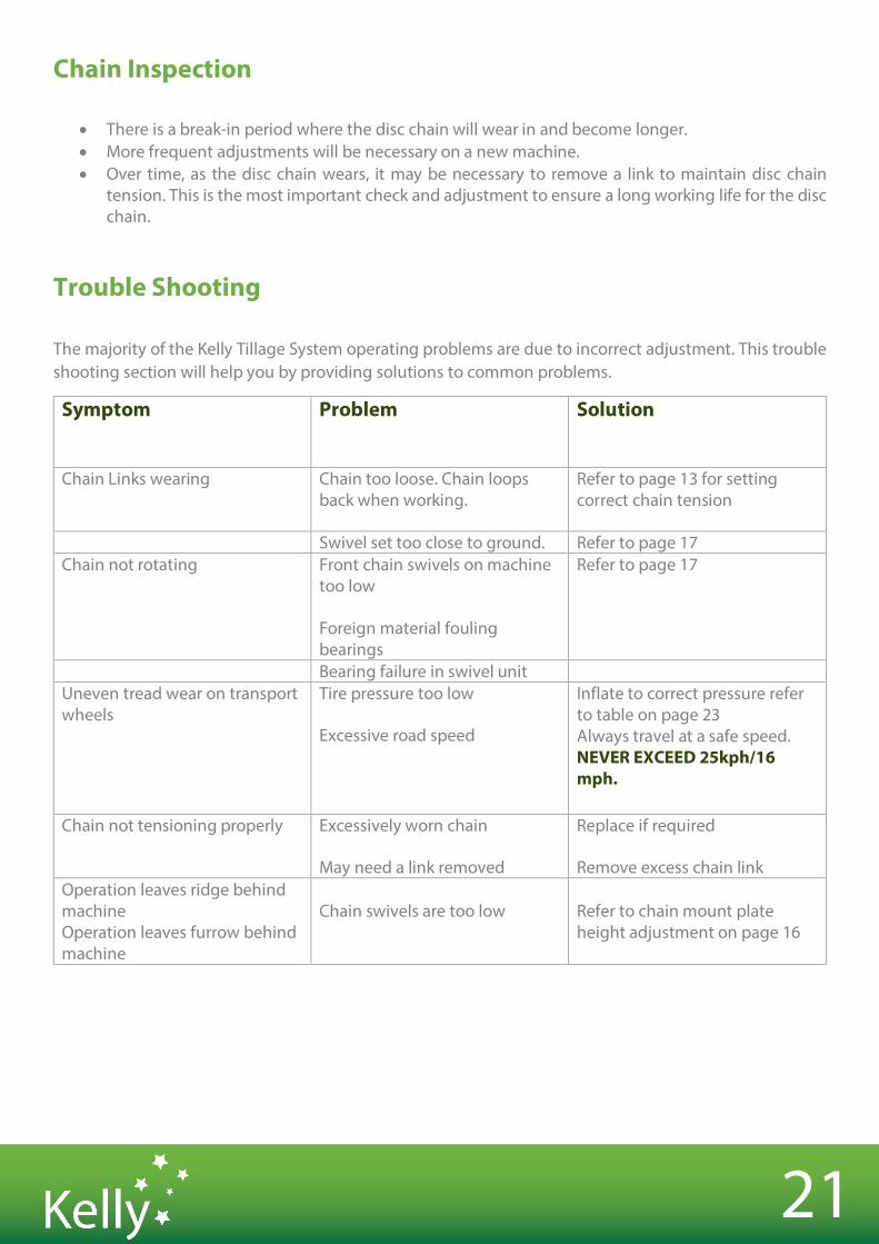
Chain Inspection
• There is a break-in period where the disc chain will wear in and become longer. • More frequent adjustments will be necessary on a new machine. • Over time, as the disc chain wears, it may be necessary to remove a link to maintain disc chain
tension. This is the most important check and adjustment to ensure a long working life for the disc chain.
Trouble Shooting
The majority of the Kelly Tillage System operating problems are due to incorrect adjustment. This trouble shooting section will help you by providing solutions to common problems.
Symptom Problem
Solution
Chain Links wearing
Chain too loose. Chain loops back when working.
Refer to page 13 for setting correct chain tension
Swivel set too close to ground. Refer to page 17 Chain not rotating Front chain swivels on machine
too low
Foreign material fouling bearings
Refer to page 17
Bearing failure in swivel unit Uneven tread wear on transport wheels
Tire pressure too low
Excessive road speed
Inflate to correct pressure refer to table on page 23 Always travel at a safe speed. NEVER EXCEED 25kph/16 mph.
Chain not tensioning properly Excessively worn chain
May need a link removed
Replace if required
Remove excess chain link Operation leaves ridge behind machine Operation leaves furrow behind machine
Chain swivels are too low
Refer to chain mount plate height adjustment on page 16

SPECIFICATIONS SECTION 5
23
SECTION 5 SPECIFICATIONS
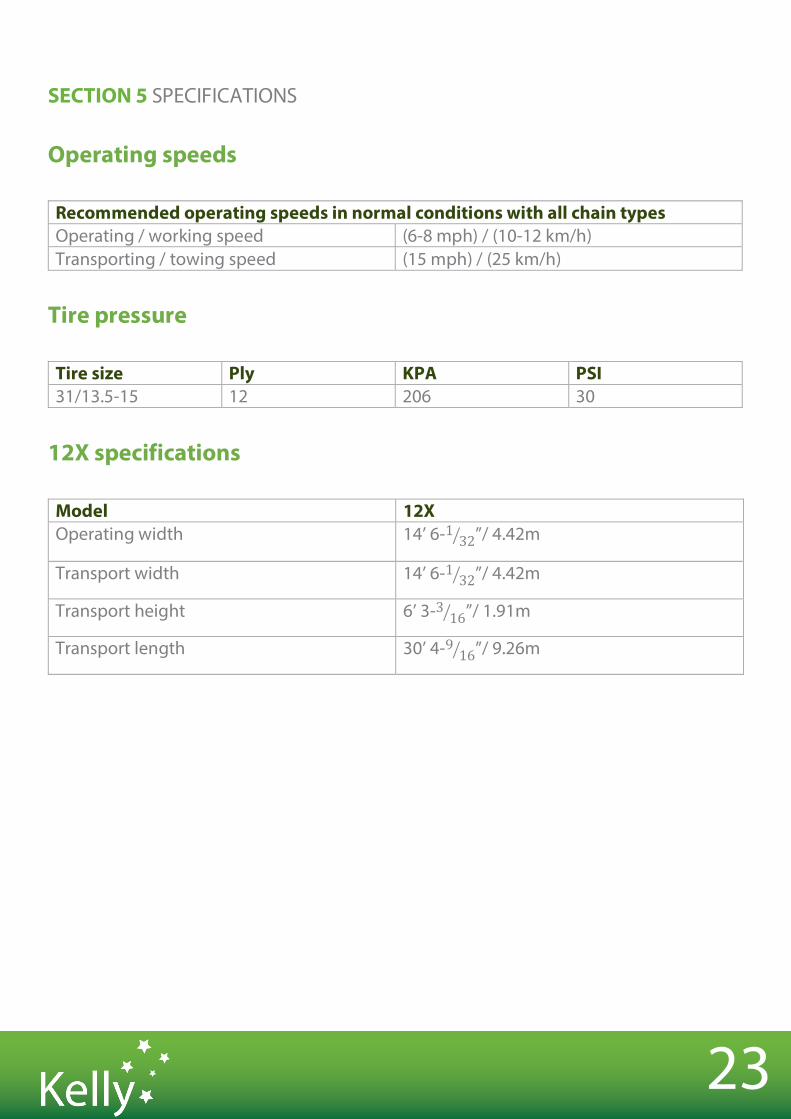
Operating speeds
Recommended operating speeds in normal conditions with all chain types Operating / working speed (6-8 mph) / (10-12 km/h) Transporting / towing speed (15 mph) / (25 km/h)
Tire pressure
Tire size Ply KPA PSI 31/13.5-15 12 206 30
12X specifications
Model 12X Operating width 14’ 6-1 32# ”/ 4.42m
Transport width 14’ 6-1 32# ”/ 4.42m
Transport height 6’ 3-3 16# ”/ 1.91m
Transport length 30’ 4-9 16# ”/ 9.26m
24
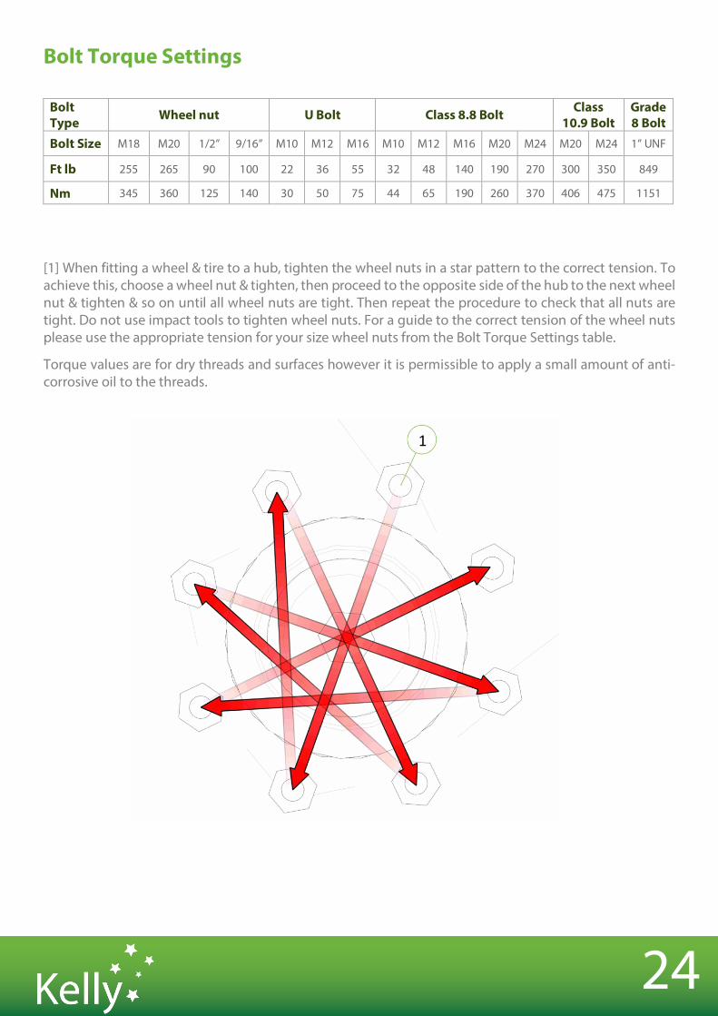
Bolt Torque Settings
Bolt Type Wheel nut U Bolt Class 8.8 Bolt Class
10.9 Bolt Grade 8 Bolt
Bolt Size M18 M20 1/2” 9/16” M10 M12 M16 M10 M12 M16 M20 M24 M20 M24 1” UNF
Ft lb 255 265 90 100 22 36 55 32 48 140 190 270 300 350 849
Nm 345 360 125 140 30 50 75 44 65 190 260 370 406 475 1151
[1] When fitting a wheel & tire to a hub, tighten the wheel nuts in a star pattern to the correct tension. To achieve this, choose a wheel nut & tighten, then proceed to the opposite side of the hub to the next wheel nut & tighten & so on until all wheel nuts are tight. Then repeat the procedure to check that all nuts are tight. Do not use impact tools to tighten wheel nuts. For a guide to the correct tension of the wheel nuts please use the appropriate tension for your size wheel nuts from the Bolt Torque Settings table.
Torque values are for dry threads and surfaces however it is permissible to apply a small amount of anti-corrosive oil to the threads.
25
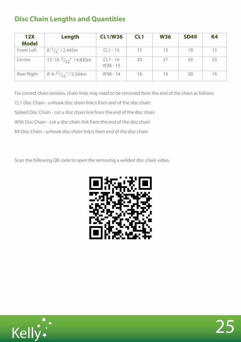
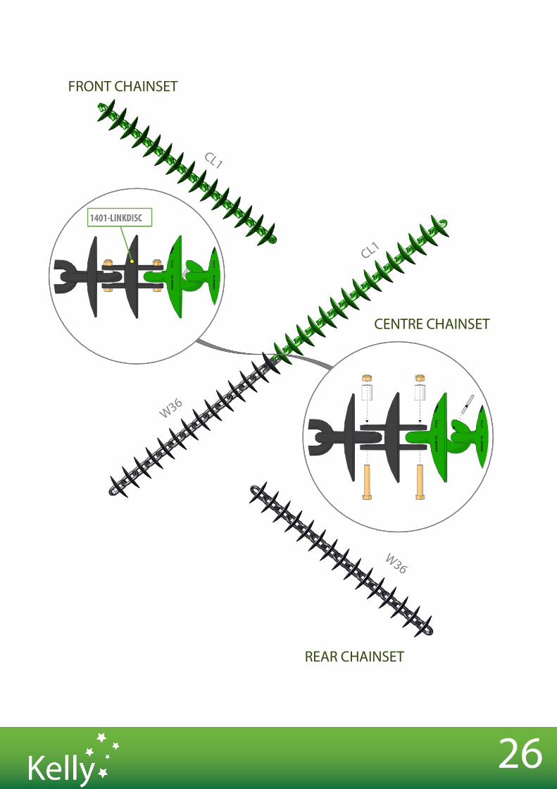
Disc Chain Lengths and Quantities
12X Model
Length CL1/W36 CL1 W36 SD49 K4
Front Left 8’ 1 4# ” / 2.445m CL1 - 15 15 13 19 15
Centre 15’ 10- 5 32# ” / 4.830m CL1 - 16 W36 - 13
30 27 39 23
Rear Right 8’ 4-15 16# ” / 2.564m W36 - 14 16 14 20 16
For correct chain tension, chain links may need to be removed from the end of the chain as follows:
CL1 Disc Chain - unhook disc chain link/s from end of the disc chain
Spiked Disc Chain - cut a disc chain link from the end of the disc chain
W36 Disc Chain - cut a disc chain link from the end of the disc chain
K4 Disc Chain - unhook disc chain link/s from end of the disc chain
Scan the following QR code to open the removing a welded disc chain video.
26
W36
CL1
W36
CL1
FRONT CHAINSET
REAR CHAINSET
CENTRE CHAINSET

PRE-DELIVERY CHECKLIST
SECTION 6
28
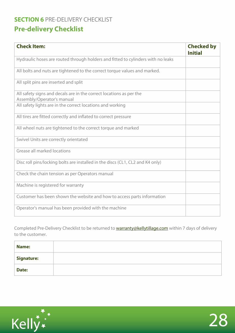
SECTION 6 PRE-DELIVERY CHECKLIST
Pre-delivery Checklist
Check Item: Checked by Initial
Hydraulic hoses are routed through holders and fitted to cylinders with no leaks
All bolts and nuts are tightened to the correct torque values and marked.
All split pins are inserted and split
All safety signs and decals are in the correct locations as per the Assembly/Operator's manual
All safety lights are in the correct locations and working
All tires are fitted correctly and inflated to correct pressure
All wheel nuts are tightened to the correct torque and marked
Swivel Units are correctly orientated
Grease all marked locations
Disc roll pins/locking bolts are installed in the discs (CL1, CL2 and K4 only)
Check the chain tension as per Operators manual
Machine is registered for warranty
Customer has been shown the website and how to access parts information
Operator's manual has been provided with the machine
Completed Pre-Delivery Checklist to be returned to [email protected] within 7 days of delivery to the customer.
Name:
Signature:
Date:

29
Notes

30
Notes

KEOPE-12X Issue A 08/03/2021