Embed Size (px)
Citation preview
KEKB Crab Cavity CommissioningRama Calaga
BNL/LARP, March 15, 2007
A Great Big Thanks To:K. Oide, K. Ohmi, H. Koiso, Y. Funakoshi & AP Group K. Akai, K. Hosoyama, K. Yamamoto & RF Group
Outline● Crab Cavity Design, RF Controls & Conditioning
● Beam Commissioning
● Optics & Collision tuning
Picture is worth a thousand words...
日本語 ME YOUTranslation Interpretation
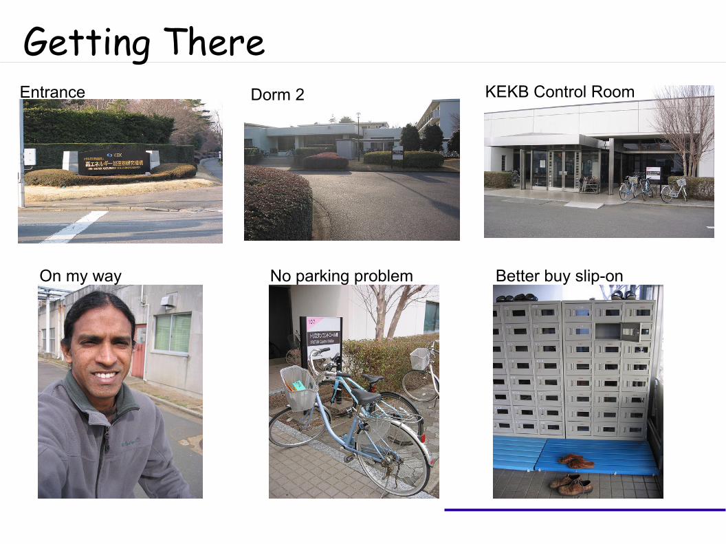
Getting ThereEntrance Dorm 2 KEKB Control Room
On my way No parking problem Better buy slip-on
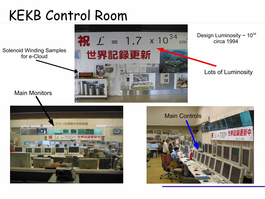
KEKB Control Room
Lots of Luminosity
Main Controls
Main Monitors
Design Luminosity ~ 1034
circa 1994
Solenoid Winding Samplesfor e-Cloud
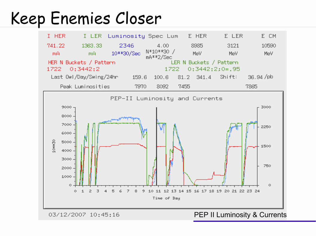
Keep Enemies Closer
PEP II Luminosity & Currents
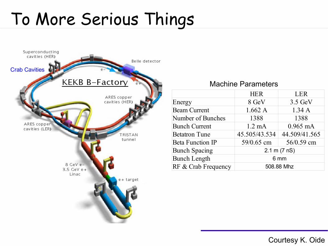
To More Serious Things
HER LEREnergy 8 GeV 3.5 GeVBeam Current 1.662 A 1.34 ANumber of Bunches 1388 1388Bunch Current 1.2 mA 0.965 mABetatron Tune 45.505/43.534 44.509/41.565Beta Function IP 59/0.65 cm 56/0.59 cmBunch Spacing 2.1 m (7 nS)
Bunch Length 6 mm
RF & Crab Frequency 508.88 Mhz
Machine Parameters
Courtesy K. Oide
Crab Cavities
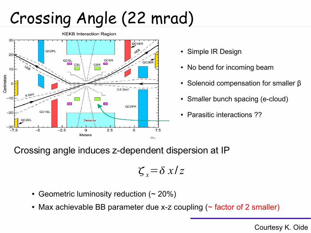
Crossing Angle (22 mrad)
● Simple IR Design
● No bend for incoming beam
● Solenoid compensation for smaller β
● Smaller bunch spacing (e-cloud)
● Parasitic interactions ??
Crossing angle induces z-dependent dispersion at IP
x= x / z
● Geometric luminosity reduction (~ 20%)
● Max achievable BB parameter due x-z coupling (~ factor of 2 smaller)
Courtesy K. Oide
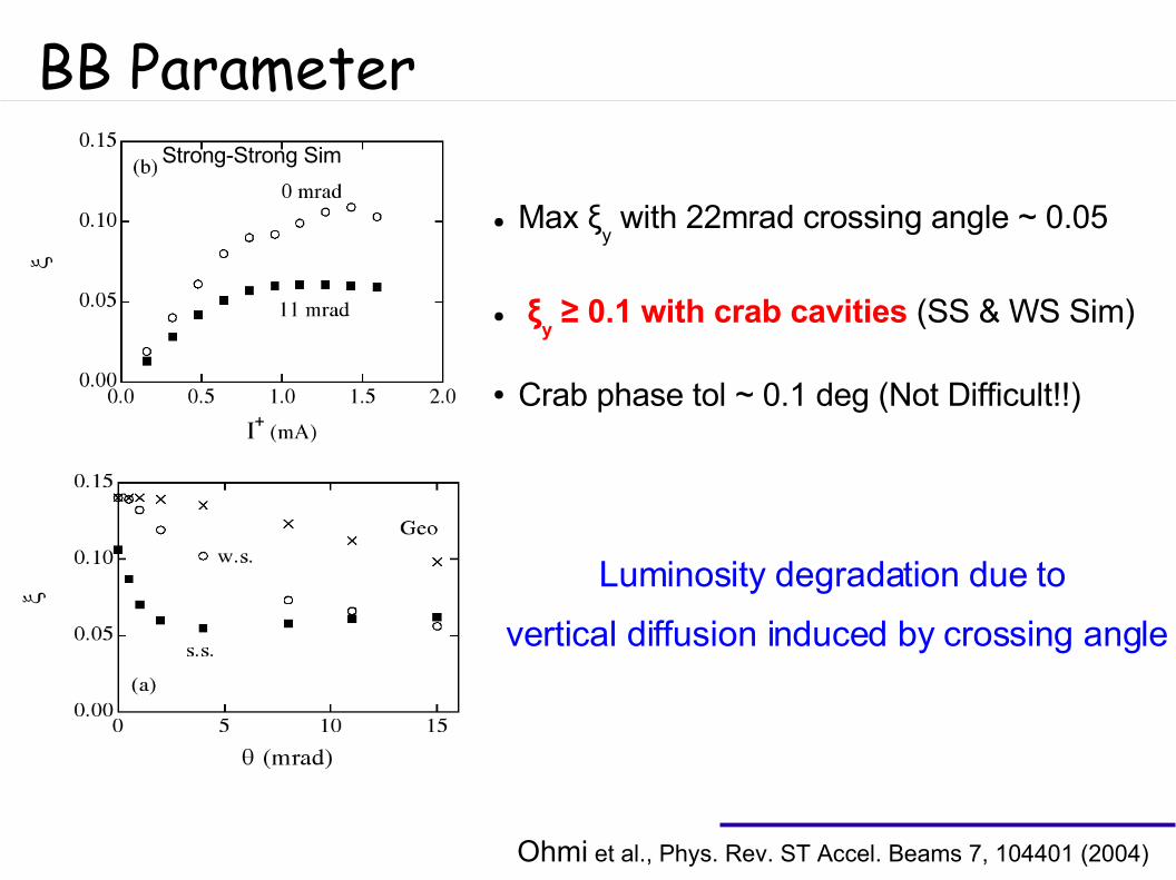
BB Parameter
● Max ξy with 22mrad crossing angle ~ 0.05
● ξy ≥ 0.1 with crab cavities (SS & WS Sim)
● Crab phase tol ~ 0.1 deg (Not Difficult!!)
Luminosity degradation due to
vertical diffusion induced by crossing angle
Ohmi et al., Phys. Rev. ST Accel. Beams 7, 104401 (2004)
Strong-Strong Sim
Crab Cavity & RF
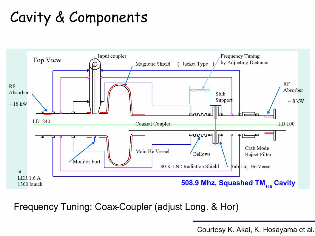
Cavity & Components
Frequency Tuning: Coax-Coupler (adjust Long. & Hor)
Courtesy K. Akai, K. Hosayama et al.
508.9 Mhz, Squashed TM110
Cavity
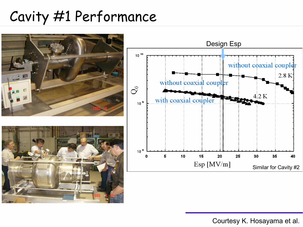
Cavity #1 Performance
Design Esp
Courtesy K. Hosayama et al.
Similar for Cavity #2
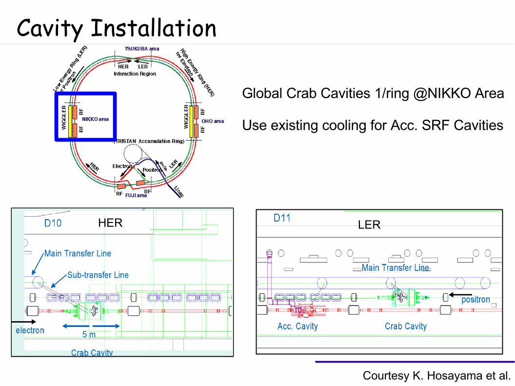
Cavity Installation
Global Crab Cavities 1/ring @NIKKO Area
Use existing cooling for Acc. SRF Cavities
Courtesy K. Hosayama et al.
HER LER
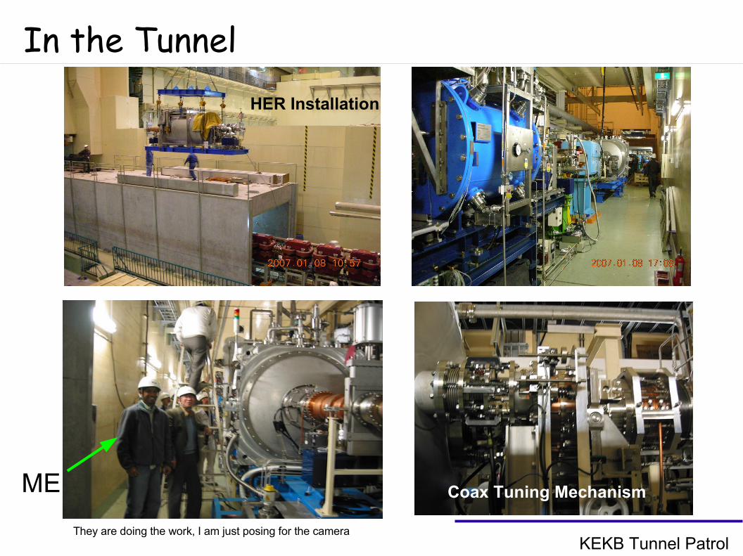
In the Tunnel
ME
They are doing the work, I am just posing for the camera
Coax Tuning Mechanism
HER Installation
KEKB Tunnel Patrol
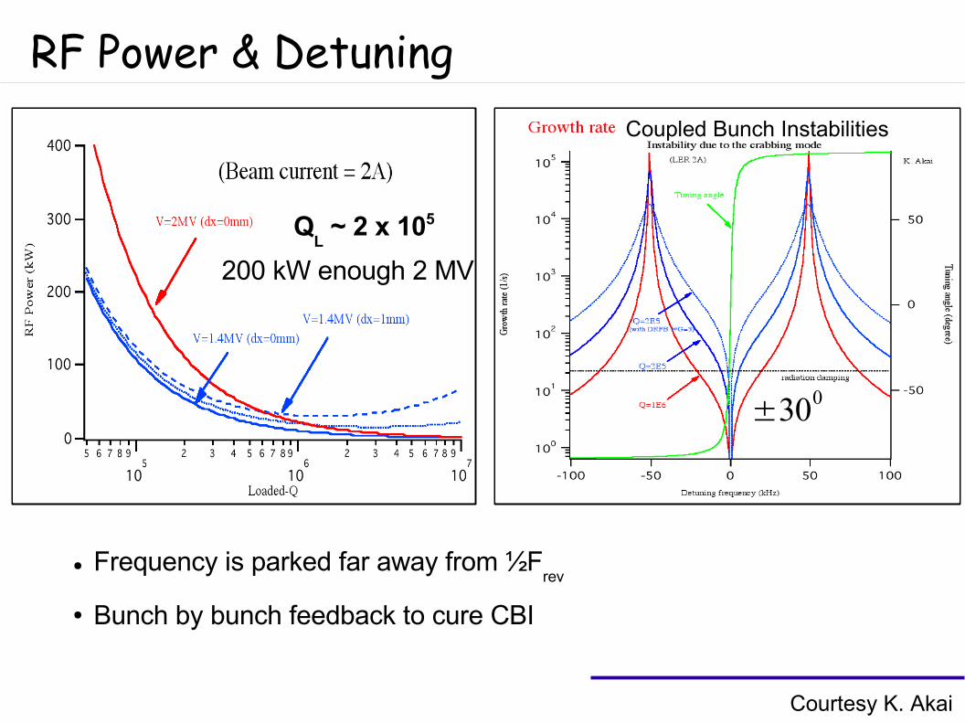
RF Power & Detuning
Courtesy K. Akai
QL ~ 2 x 10⁵
200 kW enough 2 MV
Coupled Bunch Instabilities
±300
● Frequency is parked far away from ½Frev
● Bunch by bunch feedback to cure CBI
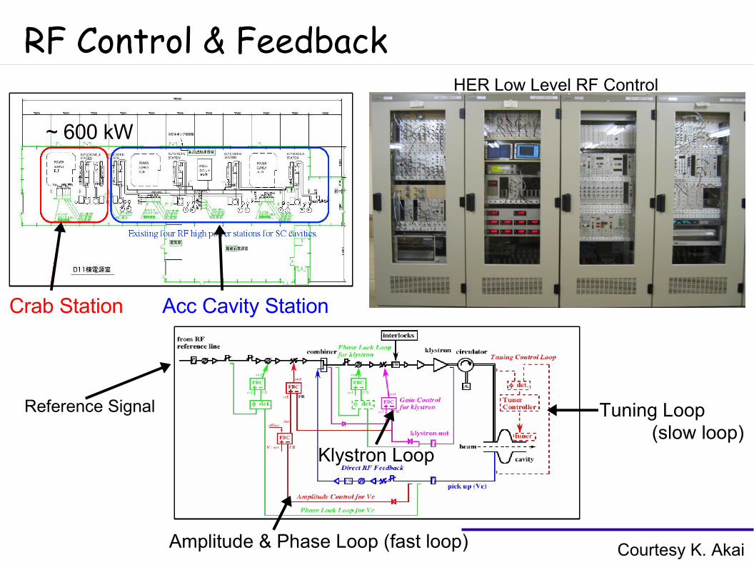
RF Control & Feedback
Courtesy K. Akai
Crab Station Acc Cavity Station
HER Low Level RF Control
Tuning Loop
Amplitude & Phase Loop (fast loop)
Klystron Loop
~ 600 kW
(slow loop)
Reference Signal
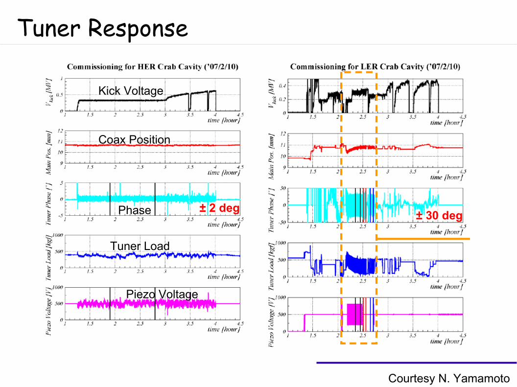
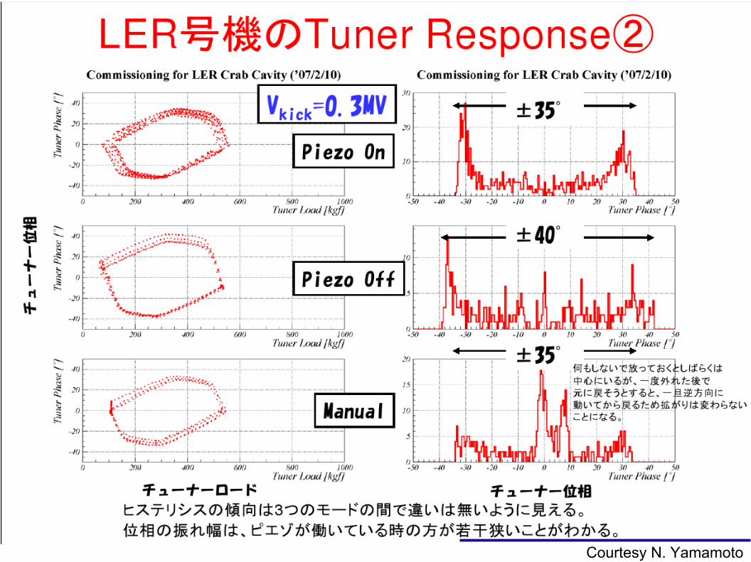
Courtesy N. Yamamoto
Tuner Response
± 2 deg± 30 deg
Kick Voltage
Coax Position
Phase
Tuner Load
Piezo Voltage
Courtesy N. Yamamoto
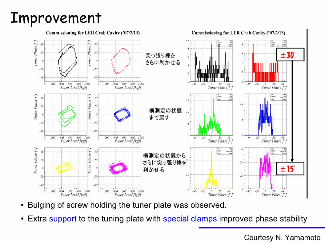
Courtesy N. Yamamoto
Improvement
● Bulging of screw holding the tuner plate was observed.
● Extra support to the tuning plate with special clamps improved phase stability
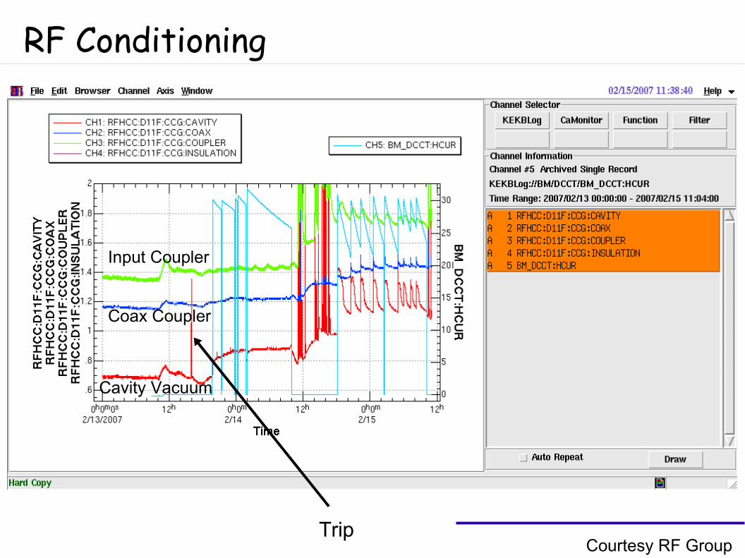
RF Conditioning
Input Coupler
Coax Coupler
Cavity Vacuum
Courtesy RF GroupTrip
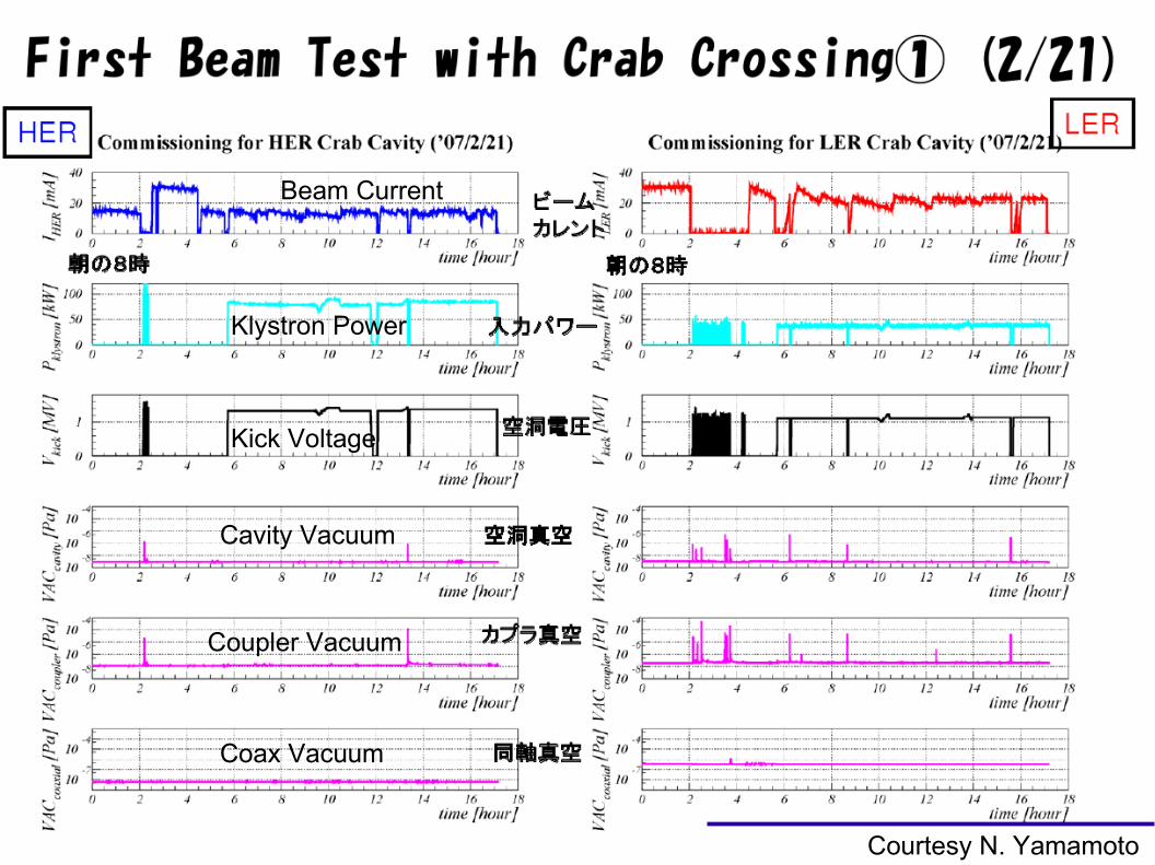
Crab Cavity with Beam
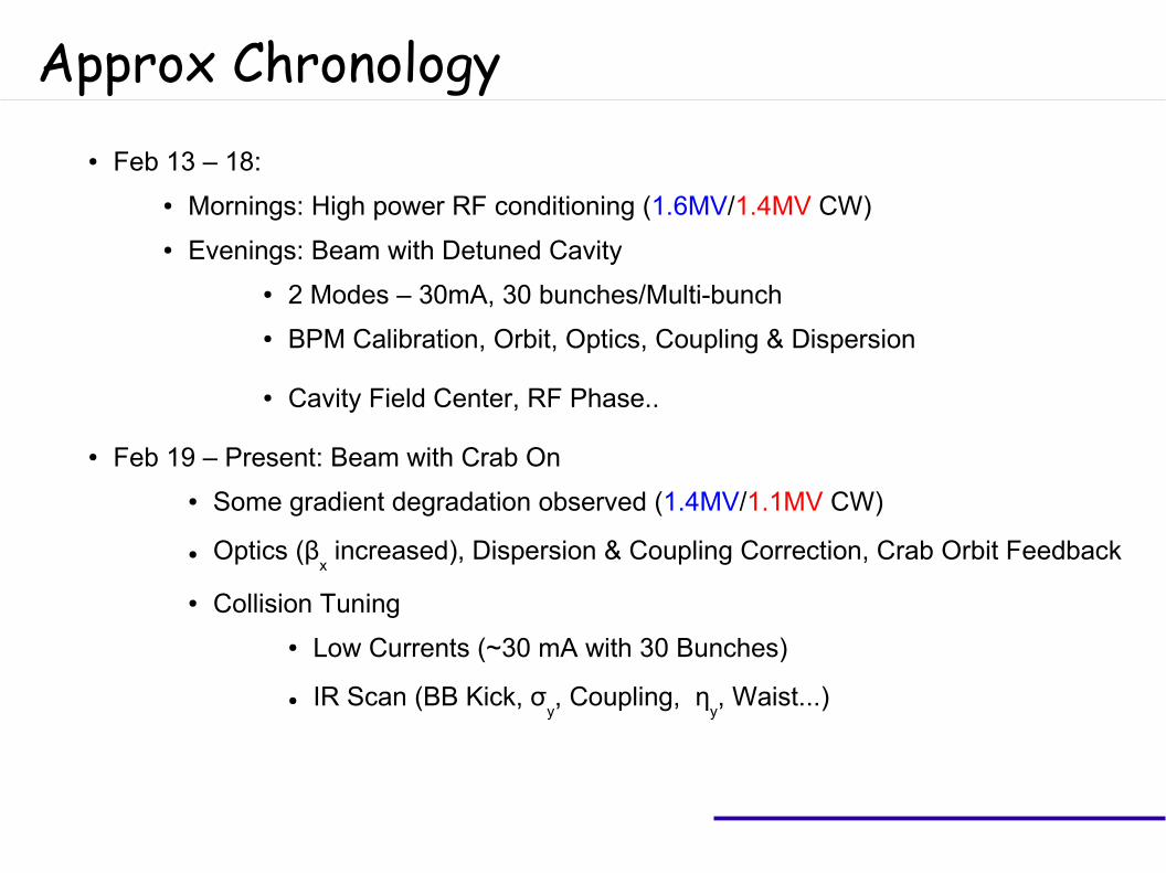
Approx Chronology● Feb 13 – 18:
● Mornings: High power RF conditioning (1.6MV/1.4MV CW)
● Evenings: Beam with Detuned Cavity
● 2 Modes – 30mA, 30 bunches/Multi-bunch
● BPM Calibration, Orbit, Optics, Coupling & Dispersion
● Cavity Field Center, RF Phase..
● Feb 19 – Present: Beam with Crab On
● Some gradient degradation observed (1.4MV/1.1MV CW)
● Optics (βx increased), Dispersion & Coupling Correction, Crab Orbit Feedback
● Collision Tuning
● Low Currents (~30 mA with 30 Bunches)
● IR Scan (BB Kick, σy, Coupling, η
y, Waist...)
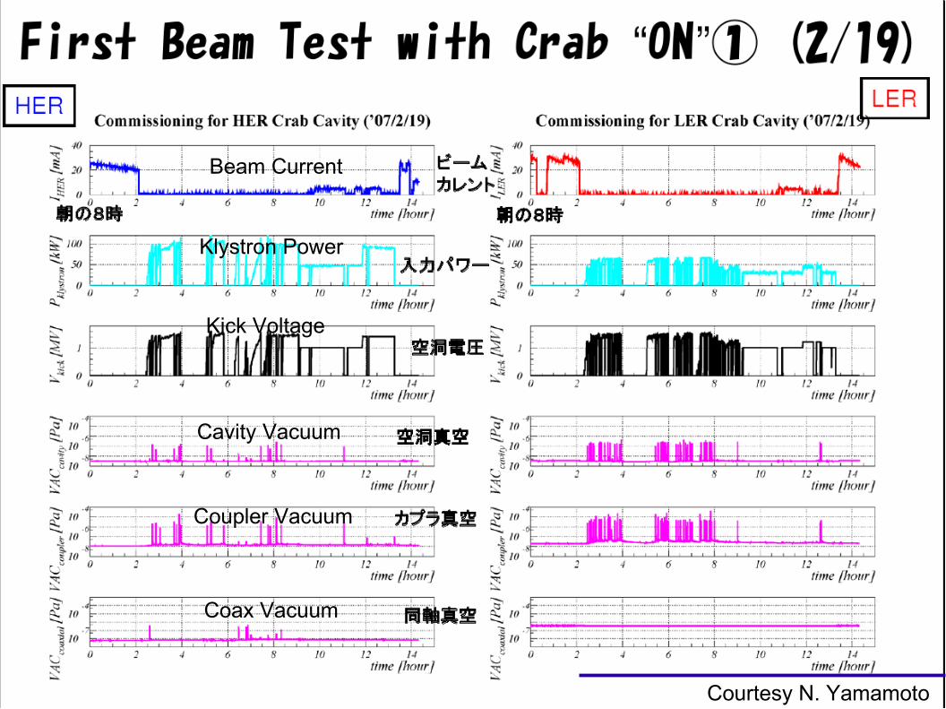
Coax Vacuum
Cavity Vacuum
Coupler Vacuum
Beam Current
Kick Voltage
Klystron Power
Courtesy N. Yamamoto
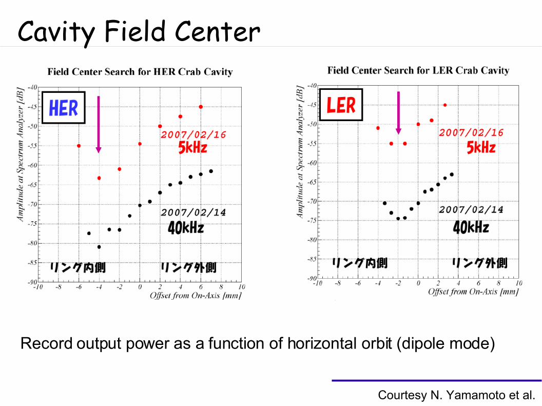
Cavity Field Center
Record output power as a function of horizontal orbit (dipole mode)
Courtesy N. Yamamoto et al.
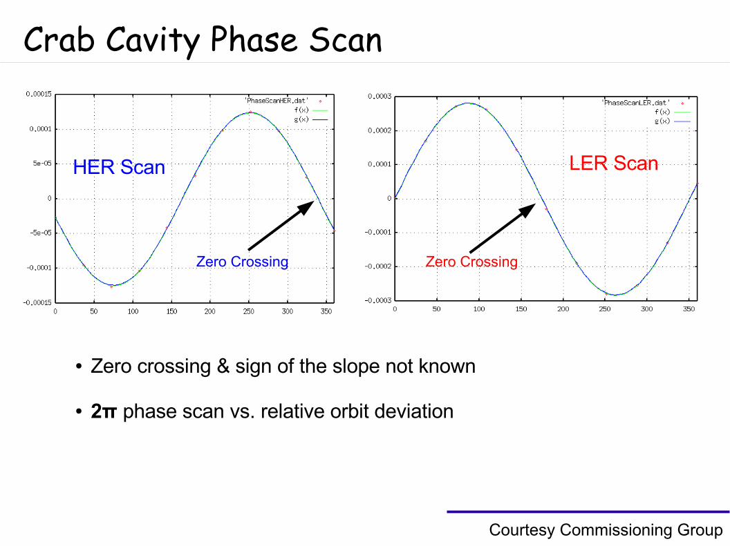
Crab Cavity Phase Scan
HER Scan LER Scan
● Zero crossing & sign of the slope not known
● 2π phase scan vs. relative orbit deviation
Zero Crossing Zero Crossing
Courtesy Commissioning Group
Beam Current
Klystron Power
Kick Voltage
Cavity Vacuum
Coupler Vacuum
Coax Vacuum
Courtesy N. Yamamoto
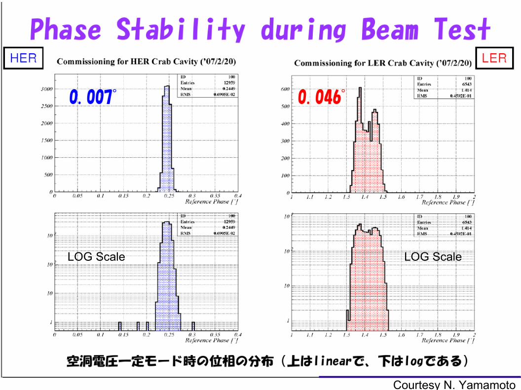
LOG Scale LOG Scale
Courtesy N. Yamamoto
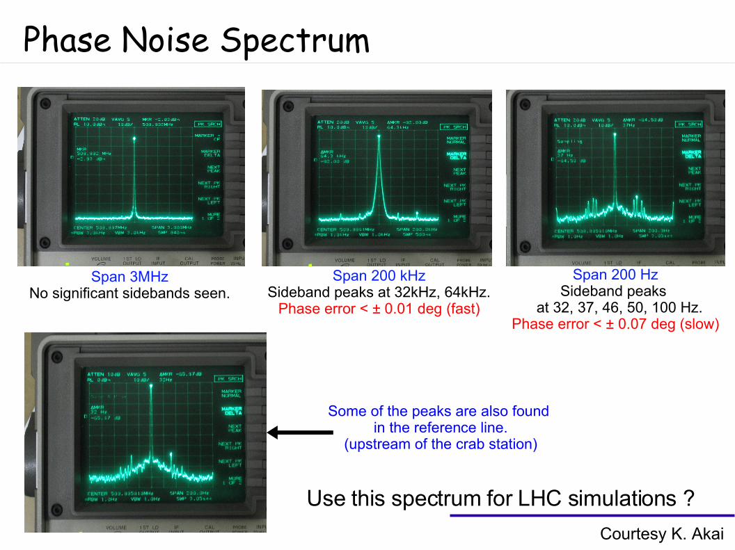
Phase Noise Spectrum
Courtesy K. Akai
Span 3MHzNo significant sidebands seen.
Span 200 kHzSideband peaks at 32kHz, 64kHz.
Phase error < ± 0.01 deg (fast)
Span 200 HzSideband peaks
at 32, 37, 46, 50, 100 Hz.Phase error < ± 0.07 deg (slow)
Some of the peaks are also found in the reference line.
(upstream of the crab station)
Use this spectrum for LHC simulations ?
Machine & Collision Tuning
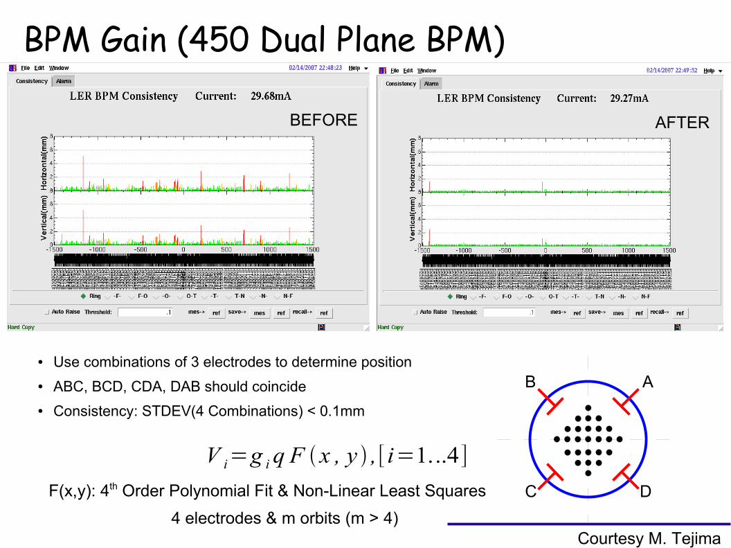
BPM Gain (450 Dual Plane BPM)
BEFORE AFTER
● Use combinations of 3 electrodes to determine position
● ABC, BCD, CDA, DAB should coincide
● Consistency: STDEV(4 Combinations) < 0.1mm
V i=g iq F x , y ,[ i=1...4]
F(x,y): 4th Order Polynomial Fit & Non-Linear Least Squares
A
D
B
C
4 electrodes & m orbits (m > 4)Courtesy M. Tejima
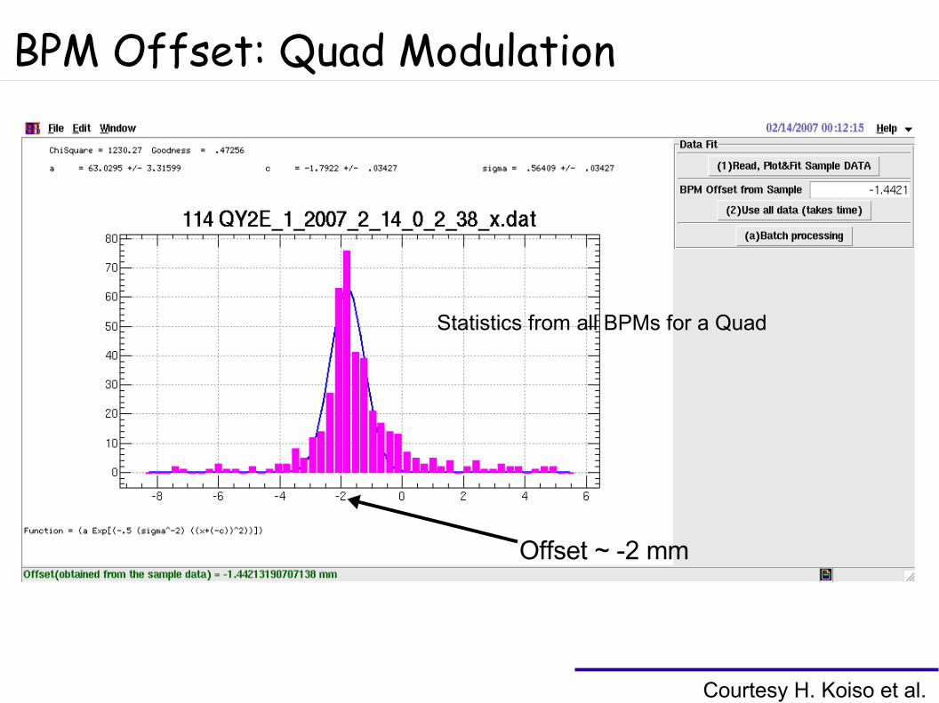
BPM Offset: Quad Modulation
Courtesy H. Koiso et al.
Offset ~ -2 mm
Statistics from all BPMs for a Quad
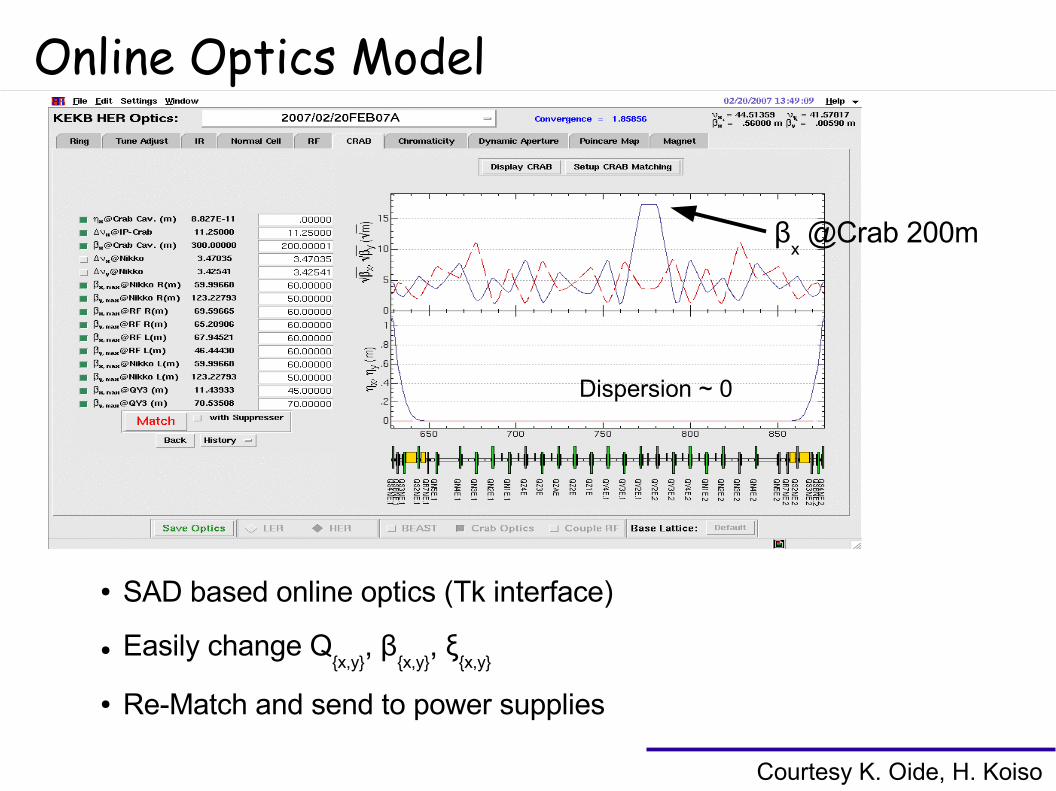
Online Optics Model
● SAD based online optics (Tk interface)
● Easily change Q{x,y}
, β{x,y}
, ξ{x,y}
● Re-Match and send to power supplies
Courtesy K. Oide, H. Koiso
βx @Crab 200m
Dispersion ~ 0
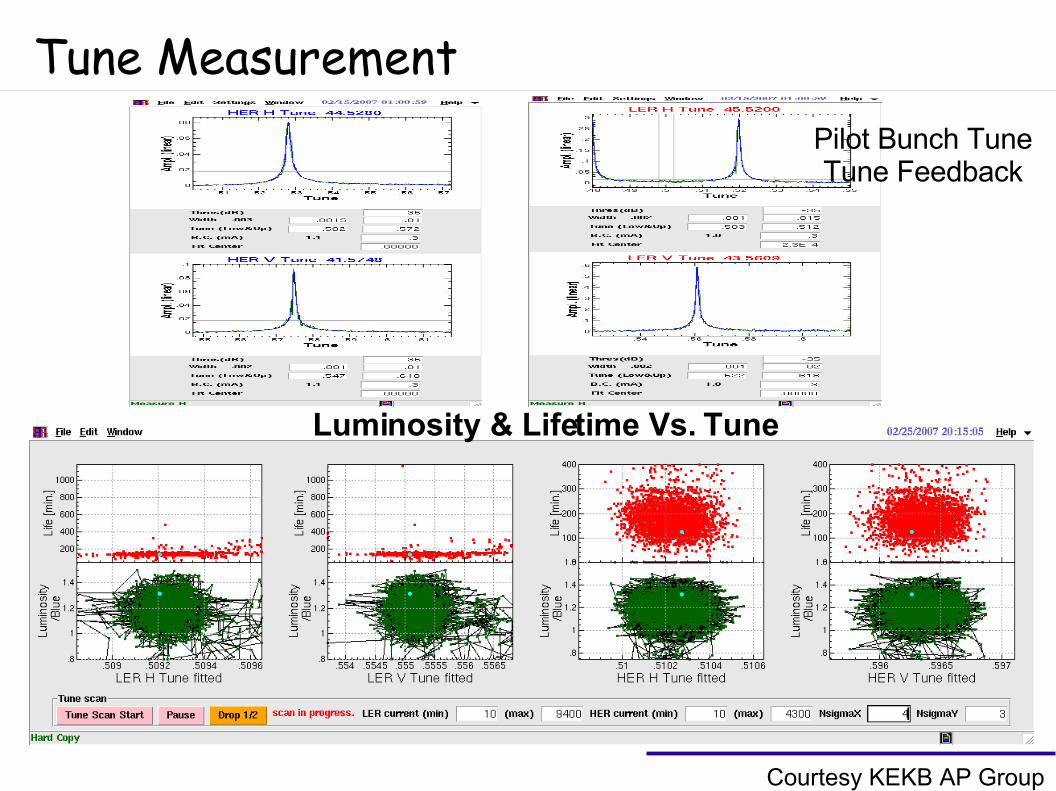
Tune MeasurementPilot Bunch TuneTune Feedback
Luminosity & Lifetime Vs. Tune
Courtesy KEKB AP Group
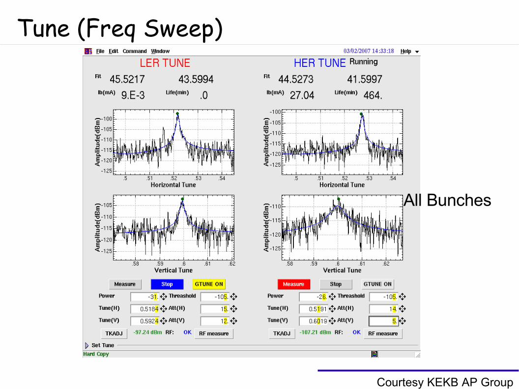
Tune (Freq Sweep)
Courtesy KEKB AP Group
All Bunches
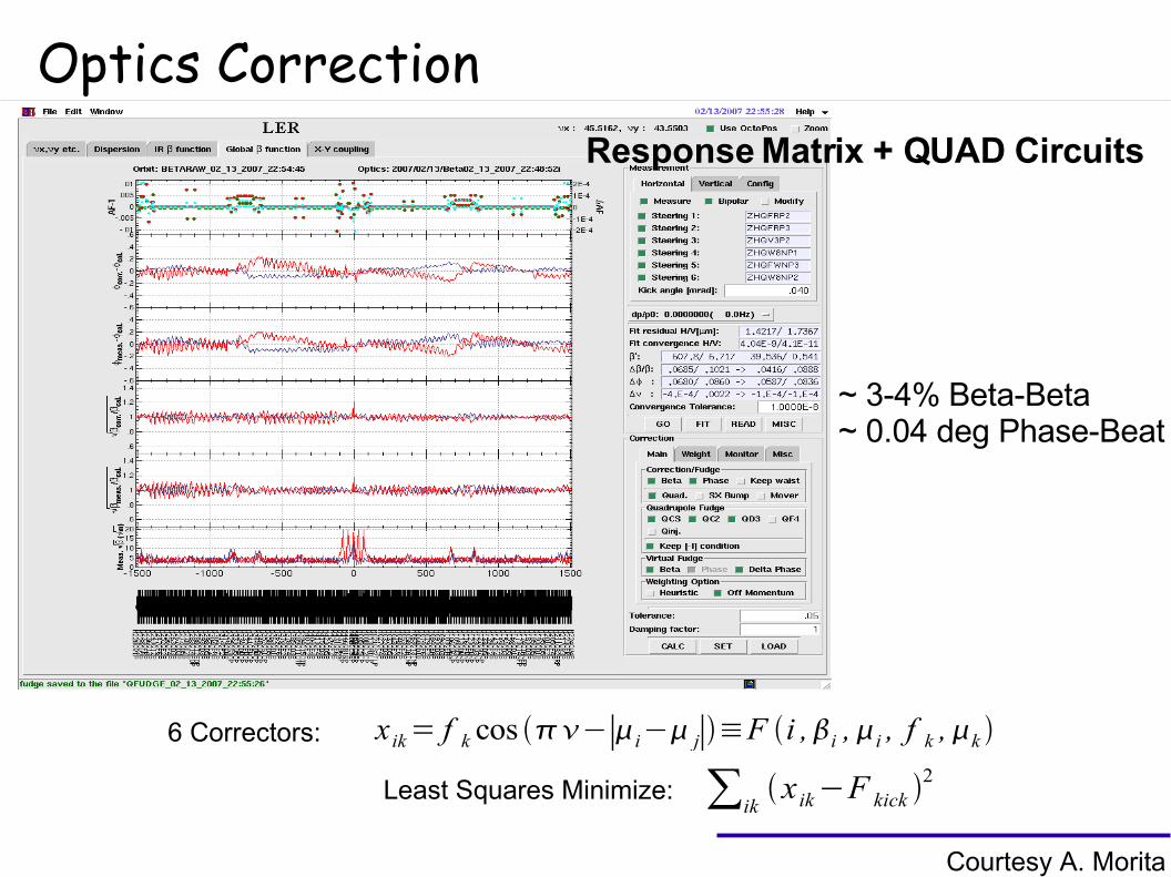
Optics CorrectionResponse Matrix + QUAD Circuits
Courtesy A. Morita
~ 3-4% Beta-Beta~ 0.04 deg Phase-Beat
x ik= f k cos −∣i− j∣≡F i ,i ,i , f k ,k
∑ikx ik−F kick
2Least Squares Minimize:
6 Correctors:
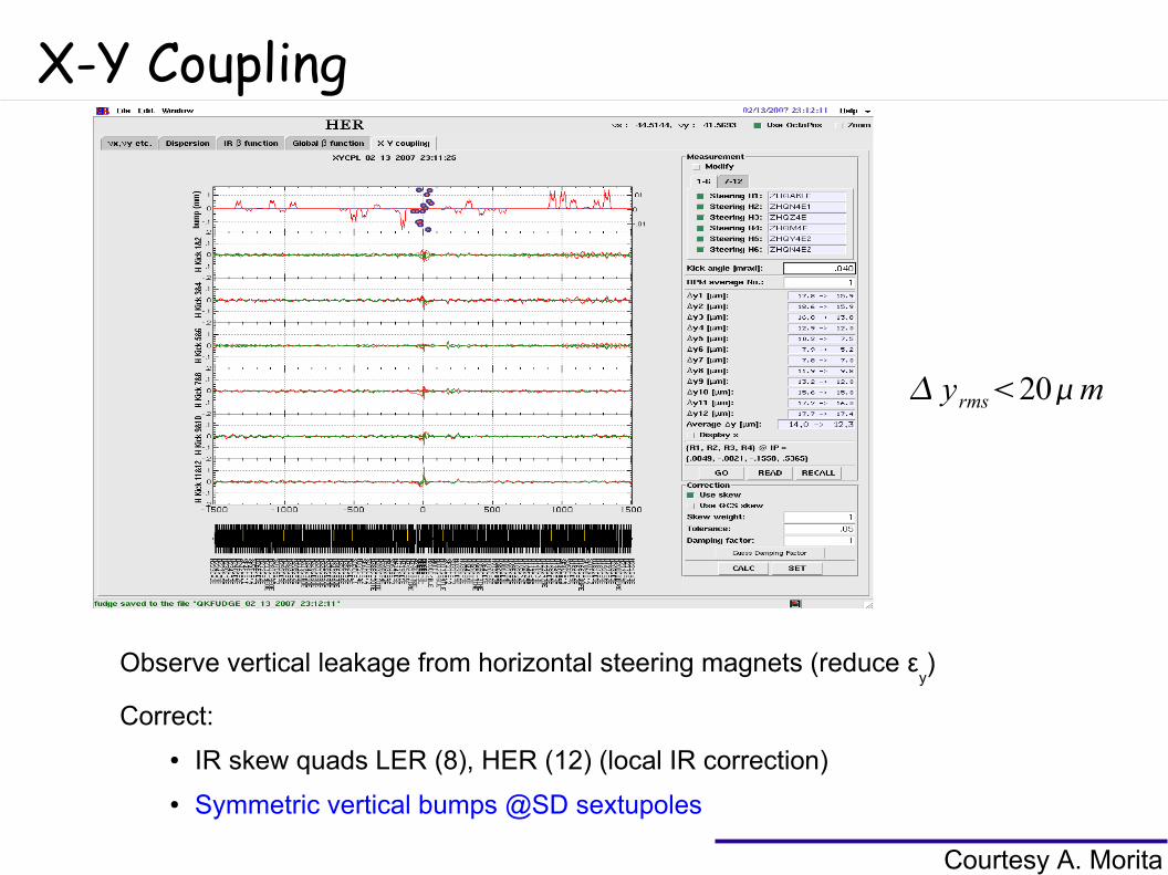
X-Y Coupling
Courtesy A. Morita
Observe vertical leakage from horizontal steering magnets (reduce εy)
Correct:
● IR skew quads LER (8), HER (12) (local IR correction)
● Symmetric vertical bumps @SD sextupoles
yrms20m
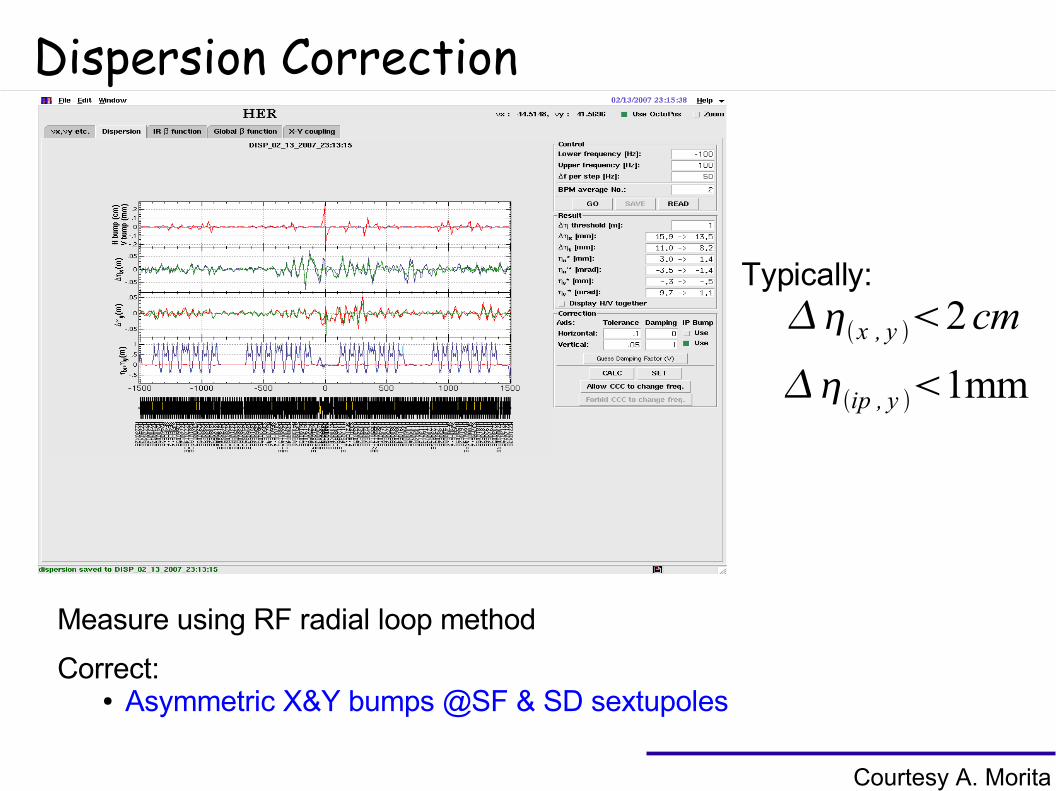
Dispersion Correction
Courtesy A. Morita
Measure using RF radial loop method
Correct:● Asymmetric X&Y bumps @SF & SD sextupoles
x , y 2cmTypically:
ip , y 1mm
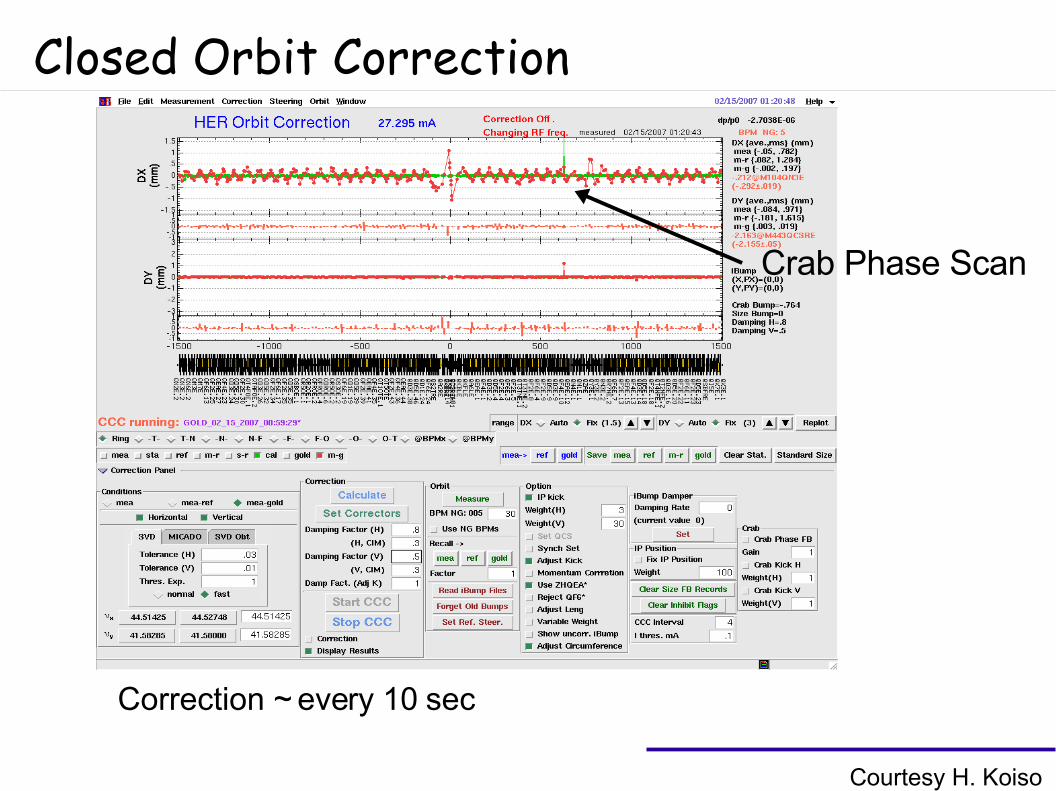
Closed Orbit Correction
Crab Phase Scan
Courtesy H. Koiso
Correction ~ every 10 sec
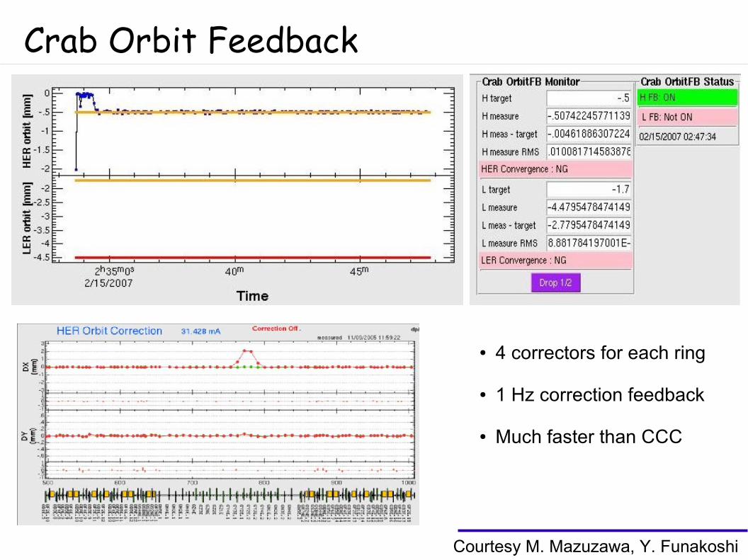
Crab Orbit Feedback
● 4 correctors for each ring
● 1 Hz correction feedback
● Much faster than CCC
Courtesy M. Mazuzawa, Y. Funakoshi
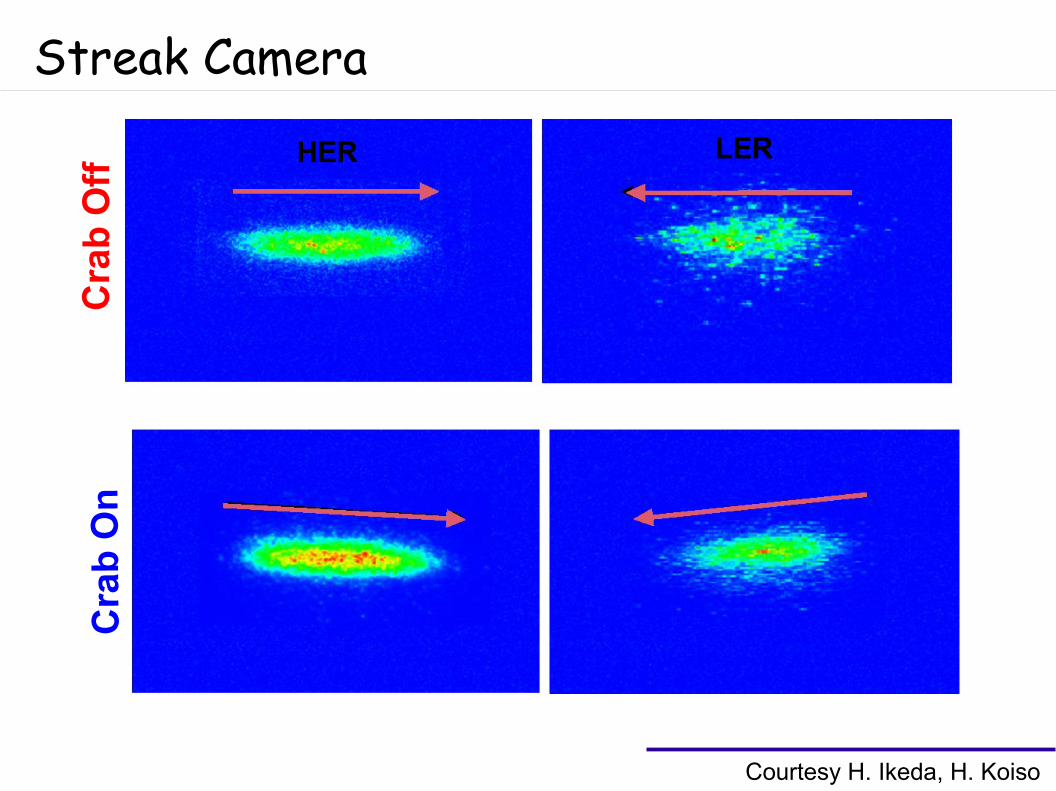
Streak Camera
Courtesy H. Ikeda, H. Koiso
HER LER
Cra
b O
ffC
rab
On
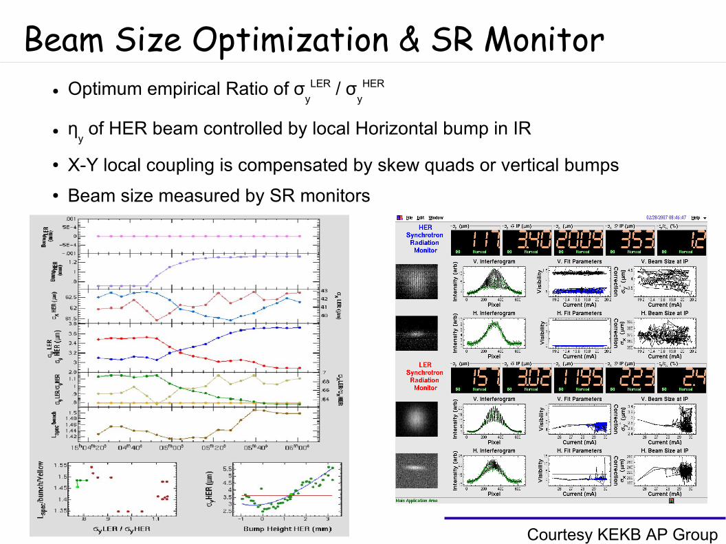
Beam Size Optimization & SR Monitor
Courtesy KEKB AP Group
● Optimum empirical Ratio of σy
LER / σy
HER
● ηy of HER beam controlled by local Horizontal bump in IR
● X-Y local coupling is compensated by skew quads or vertical bumps
● Beam size measured by SR monitors
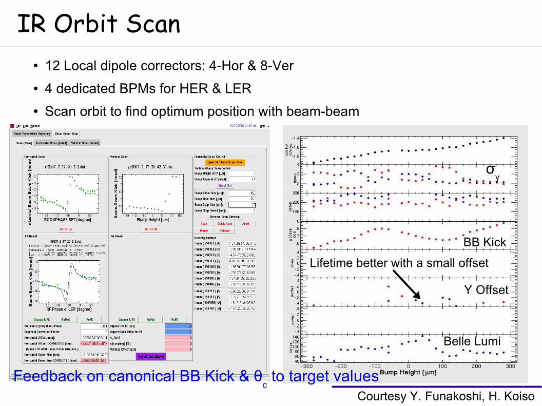
IR Orbit Scan● 12 Local dipole correctors: 4-Hor & 8-Ver
● 4 dedicated BPMs for HER & LER
● Scan orbit to find optimum position with beam-beam
Courtesy Y. Funakoshi, H. Koiso
Feedback on canonical BB Kick & θc to target values
BB Kick
Belle Lumi
Y Offset
σy
Lifetime better with a small offset
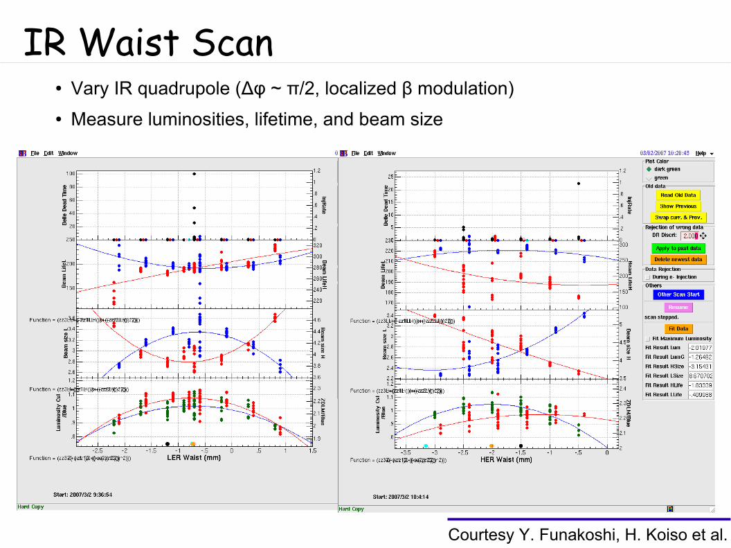
IR Waist Scan● Vary IR quadrupole (Δφ ~ π/2, localized β modulation)
● Measure luminosities, lifetime, and beam size
Courtesy Y. Funakoshi, H. Koiso et al.
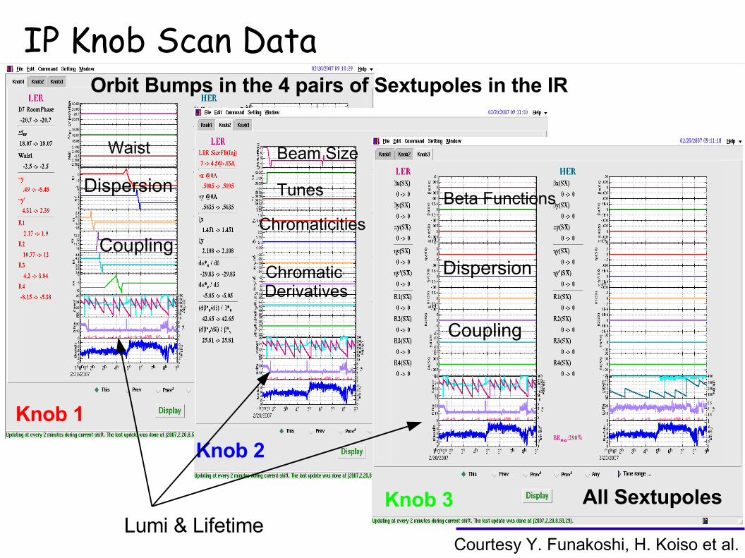
IP Knob Scan DataOrbit Bumps in the 4 pairs of Sextupoles in the IR
Knob 1
Knob 2
Knob 3 All Sextupoles
Dispersion
CouplingChromaticities
Tunes
Beam Size
Chromatic Derivatives
Lumi & Lifetime
Coupling
Dispersion
Beta Functions
Waist
Courtesy Y. Funakoshi, H. Koiso et al.
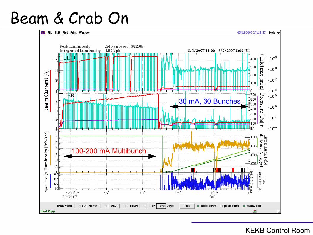
Beam & Crab On
KEKB Control Room
100-200 mA Multibunch
30 mA, 30 Bunches
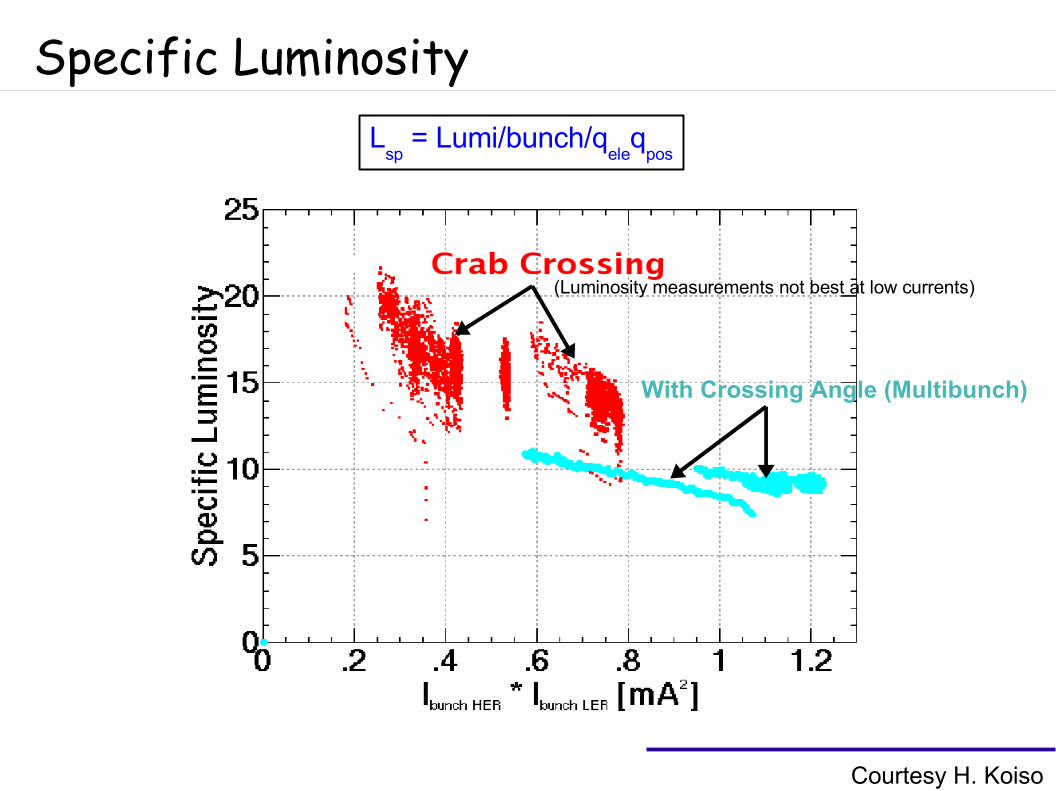
Specific Luminosity
Courtesy H. Koiso
Lsp
= Lumi/bunch/qele
qpos
With Crossing Angle (Multibunch)
(Luminosity measurements not best at low currents)
Conclusions● Almost 15 yrs of R&D on the idea of crab cavities
● Two cavities installed Jan 2007 and successfully crabbed the beam
● More tuning needed for luminosity optimization, also increase LER Vcrab
~1.4 MV
● Stability and vacuum issues at high currents ??
● Next milestone ~ 200 mA to observe benefits from head-on collision
Many Thanks to K. Oide, K.Ohmi & KEKB Team !!And Good Bye Japan...
Need to benchmark Ohmi's Beam-Beam code with HEADTAIL (or others) including
LHC sector map + crab cavity for phase tolerances and such for LHC
KEK-B group enthusiastic about LHC crab proposal, future collaboration foreseen