Embed Size (px)
Citation preview

Keithley KPCMCIA-8AO Series
Using DriverLINX with Your Hardware

2
Information in this document is subject to change without notice. The software described is this document is furnished under a license agreement. The software may be used or copied only in accordance with the terms of the agreement.
SCIENTIFIC SOFTWARE TOOLS, INC. SHALL NOT BE LIABLE FOR ANY SPECIAL, INCIDENTAL, OR CONSEQUENTIAL DAMAGES RELATED TO THE USE OF THIS PRODUCT. THIS PRODUCT IS NOT DESIGNED WITH COMPONENTS OF A LEVEL OF RELIABILITY SUITABLE FOR USE IN LIFE SUPPORT OR CRITICAL APPLICATIONS.
This document may not, in whole or in part, be copied, photocopied, reproduced, translated or reduced to any electronic medium or machine readable form without prior written consent from Scientific Software Tools, Inc.
Keithley KPCMCIA-8AO Series: Using DriverLINX with your Hardware Copyright 1998, 2001, Scientific Software Tools, Inc. All rights reserved.
SST 14-0801-1
DriverLINX, SSTNET, and LabOBJX are registered trademarks and DriverLINX/VB is a trademark of Scientific Software Tools, Inc. MetraByte and KPCMCIA are trademarks of Keithley Instruments, Inc. Microsoft and Windows are registered trademarks and Visual C++ and Visual Basic are trademarks of Microsoft Corporation. Borland is a registered trademark and Borland C++ and Delphi are trademarks of Borland International, Inc. All other brand and product names are trademarks or registered trademarks of their respective companies.

Keithley KPCMCIA-8AO Series Contents • 3
Contents
Preface 5
Software License and Software Disclaimer of Warranty............................................................5 About DriverLINX.....................................................................................................................7 About This User’s Guide ...........................................................................................................7 Conventions Used in This Manual .............................................................................................8
Configuring the KPCMCIA-8AO Series 9
Introduction................................................................................................................................9 Configure DriverLINX Device Dialog.......................................................................................9
Device Subsystem Page .............................................................................................11 Analog Output Subsystem Page.................................................................................13 Digital Input Subsystem Page ....................................................................................15 Digital Output Subsystem Page .................................................................................19 Counter/Timer Subsystem Page.................................................................................21
Using the KPCMCIA-8AO Series with DriverLINX 23
Introduction..............................................................................................................................23 DriverLINX Hardware Model for KPCMCIA-8AO Series .....................................................23
DriverLINX Subsystems............................................................................................23 DriverLINX Modes ...................................................................................................24 DriverLINX Operations and Events ..........................................................................25 Logical Channels .......................................................................................................27 Buffers .......................................................................................................................27
Connecting Signals to the KPCMCIA-8AO Series ..................................................................28 Analog Output Subsystem Signals .............................................................................28 Digital Input Subsystem Signals ................................................................................28 Digital Output Subsystem Signals..............................................................................28 Counter/Timer Subsystem Signals .............................................................................29
Device Subsystem ....................................................................................................................30 Device Modes ............................................................................................................30 Device Operations .....................................................................................................30
Analog Output Subsystem........................................................................................................31 Analog Output Modes................................................................................................31 Analog Output Operations .........................................................................................31 Analog Output Timing Events ...................................................................................31 Analog Output Start Events .......................................................................................34 Analog Output Stop Events........................................................................................36 Analog Output Channels............................................................................................37 Analog Output Buffers...............................................................................................40 Analog Output Data Coding ......................................................................................41 Analog Output Messages ...........................................................................................41
Digital Input Subsystem...........................................................................................................43

4 • Contents Keithley KPCMCIA-8AO Series
Digital Input Modes ...................................................................................................43 Digital Input Operations.............................................................................................43 Digital Input Timing Events.......................................................................................43 Digital Input Start Events...........................................................................................46 Digital Input Stop Events...........................................................................................48 Digital Input Channels ...............................................................................................49 Digital Input Buffers ..................................................................................................52 Digital Input Messages...............................................................................................52
Digital Output Subsystem.........................................................................................................54 Digital Output Modes ................................................................................................54 Digital Output Operations..........................................................................................54 Digital Output Timing Events ....................................................................................54 Digital Output Start Events ........................................................................................57 Digital Output Stop Events ........................................................................................59 Digital Output Channels.............................................................................................60 Digital Output Buffers ...............................................................................................63 Digital Output Messages ............................................................................................63
Counter/Timer Subsystem........................................................................................................65
Uninstalling DriverLINX 67
How do I uninstall DriverLINX? .............................................................................................67
Troubleshooting 72
Solving Problems .....................................................................................................................72 Solving Problems Installing Drivers ..........................................................................72 Solving Problems Configuring the Drivers ................................................................72 Solving Problems Loading Drivers ............................................................................73
Generating a DriverLINX Configuration Report......................................................................76 What is in the Report?................................................................................................76 How do I Generate the Report?..................................................................................76
Glossary of Terms 77

Keithley KPCMCIA-8AO Series Preface • 5
Preface
Software License and Software Disclaimer of Warranty
This is a legal document which is an agreement between you, the Licensee, and Scientific Software Tools, Inc. By opening this sealed diskette package, Licensee agrees to become bound by the terms of this Agreement, which include the Software License and Software Disclaimer of Warranty.
This Agreement constitutes the complete Agreement between Licensee and Scientific Software Tools, Inc. If Licensee does not agree to the terms of this Agreement, do not open the diskette package. Promptly return the unopened diskette package and the other items (including written materials, binders or other containers, and hardware, if any) that are part of this product to Scientific Software Tools, Inc. for a full refund. No refunds will be given for products that have opened disk packages or missing components.
Licensing Agreement
Copyright. The software and documentation is owned by Scientific Software Tools, Inc. and is protected by both United States copyright laws and international treaty provisions. Scientific Software Tools, Inc. authorizes the original purchaser only (Licensee) to either (a) make one copy of the software solely for backup or archival purposes, or (b) transfer the software to a single hard disk only. The written materials accompanying the software may not be duplicated or copied for any reason.
Trade Secret. Licensee understands and agrees that the software is the proprietary and confidential property of Scientific Software Tools, Inc. and a valuable trade secret. Licensee agrees to use the software only for the intended use under this License, and shall not disclose the software or its contents to any third party.
Copy Restrictions. The Licensee may not modify or translate the program or related documentation without the prior written consent of Scientific Software Tools, Inc. All modifications, adaptations, and merged portions of the software constitute the software licensed to the Licensee, and the terms and conditions of this agreement apply to same. Licensee may not distribute copies, including electronic transfer of copies, of the modified, adapted or merged software or accompanying written materials to others. Licensee agrees not to reverse engineer, decompile or disassemble any part of the software.
Unauthorized copying of the software, including software that has been modified, merged, or included with other software, or of the written materials is expressly forbidden. Licensee may not rent, transfer or lease the software to any third parties. Licensee agrees to take all reasonable steps to protect Scientific Software Tools’ software from theft, disclosure or use contrary to the terms of the License.
License. Scientific Software Tools, Inc. grants the Licensee only a non-exclusive right to use the serialized copy of the software on a single terminal connected to a single computer. The Licensee may not network the software or use it on more than one computer or computer terminal at the same time.
Term. This License is effective until terminated. This License will terminate automatically without notice from Scientific Software Tools, Inc. if Licensee fails to comply with any term or condition of this License. The Licensee agrees upon such termination to return or destroy the written materials and all copies of the software. The Licensee may terminate the agreement by returning or destroying the program and documentation and all copies thereof.

6 • Preface Keithley KPCMCIA-8AO Series
Limited Warranty
Scientific Software Tools, Inc. warrants that the software will perform substantially in accordance with the written materials and that the program disk, instructional manuals and reference materials are free from defects in materials and workmanship under normal use for 90 days from the date of receipt. All express or implied warranties of the software and related materials are limited to 90 days.
Except as specifically set forth herein, the software and accompanying written materials (including instructions for use) are provided “as is” without warranty of any kind. Further, Scientific Software Tools, Inc. does not warrant, guarantee, or make any representations regarding the use, or the results of the use, of the software or written materials in terms of correctness, accuracy, reliability, currentness, or otherwise. The entire risk as to the results and performance of the software is assumed by Licensee and not by Scientific Software Tools, Inc. or its distributors, agents or employees.
EXCEPT AS SET FORTH HEREIN, THERE ARE NO OTHER WARRANTIES, EITHER EXPRESS OR IMPLIED, INCLUDING BUT NOT LIMITED TO IMPLIED WARRANTIES OF MERCHANTABILITY AND FITNESS FOR A PARTICULAR PURPOSE, WITH RESPECT TO THE SOFTWARE, THE ACCOMPANYING WRITTEN MATERIALS, AND ANY ACCOMPANYING HARDWARE.
Remedy. Scientific Software Tools’ entire liability and the Licensee’s exclusive remedy shall be, at Scientific Software Tools’ option, either (a) return of the price paid or (b) repair or replacement of the software or accompanying materials. In the event of a defect in material or workmanship, the item may be returned within the warranty period to Scientific Software Tools for a replacement without charge, provided the licensee previously sent in the limited warranty registration card to Scientific Software Tools, Inc., or can furnish proof of the purchase of the program. This remedy is void if failure has resulted from accident, abuse, or misapplication. Any replacement will be warranted for the remainder of the original warranty period.
NEITHER SCIENTIFIC SOFTWARE TOOLS, INC. NOR ANYONE ELSE WHO HAS BEEN INVOLVED IN THE CREATION, PRODUCTION, SALE OR DELIVERY OF THIS PRODUCT SHALL BE LIABLE FOR ANY DIRECT, INDIRECT, CONSEQUENTIAL, OR INCIDENTAL DAMAGES (INCLUDING DAMAGES FOR LOSS OF BUSINESS PROFITS, BUSINESS INTERRUPTION, LOSS OF BUSINESS INFORMATION AND THE LIKE) ARISING OUT OF THE USE OF OR THE INABILITY TO USE SUCH PRODUCT EVEN IF SCIENTIFIC SOFTWARE TOOLS HAS BEEN ADVISED OF THE POSSIBILITY OF SUCH DAMAGES. BECAUSE SOME JURISDICTIONS DO NOT ALLOW THE EXCLUSION OR LIMITATION OF LIABILITY FOR CONSEQUENTIAL OR INCIDENTAL DAMAGES, OR LIMITATIONS ON DURATION OF AN IMPLIED WARRANTY, THE ABOVE LIMITATIONS MAY NOT APPLY TO LICENSEE.
This agreement is governed by the laws of the Commonwealth of Pennsylvania.

Keithley KPCMCIA-8AO Series Preface • 7
About DriverLINX Welcome to DriverLINX for Microsoft Windows, the high-performance real-time data-acquisition device drivers for Windows application development.
DriverLINX is a language- and hardware-independent application-programming interface designed to support hardware manufacturers’ high-speed analog, digital, and counter/timer data-acquisition boards in Windows. DriverLINX is a multi-user and multitasking data-acquisition resource manager providing more than 100 services for foreground and background data acquisition tasks.
Included with your DriverLINX package are the following items:
• The DriverLINX API DLLs and drivers supporting your data-acquisition hardware
• Learn DriverLINX, an interactive learning and demonstration program for DriverLINX that includes a Digital Storage Oscilloscope
• Source code for the sample programs
• The DriverLINX Application Programming Interface files for your compiler
• DriverLINX On-line Help System
• DriverLINX Analog I/O Programming Guide
• DriverLINX Technical Reference Manual
• Supplemental Documentation on DriverLINX and your data acquisition hardware
About This User’s Guide The purpose of this manual is to help you quickly learn how to configure and use the hardware features of Keithley’s KPCMCIA-8AO Series cards with DriverLINX.
• For more information on the DriverLINX API, please see the DriverLINX Technical Reference Manual.
• For additional help programming your board, please examine the source code examples on the Distribution Disks.
This manual contains the following chapters:
Configuring the KPCMCIA-8AO Series
Shows how to configure the KPCMCIA-8AO Series using the Configure DriverLINX Device dialog box.
Using the KPCMCIA-8AO Series with DriverLINX
Shows how to set up DriverLINX with the Edit Service Request dialog box to use KPCMCIA-8AO Series hardware features.
8 • Preface Keithley KPCMCIA-8AO Series
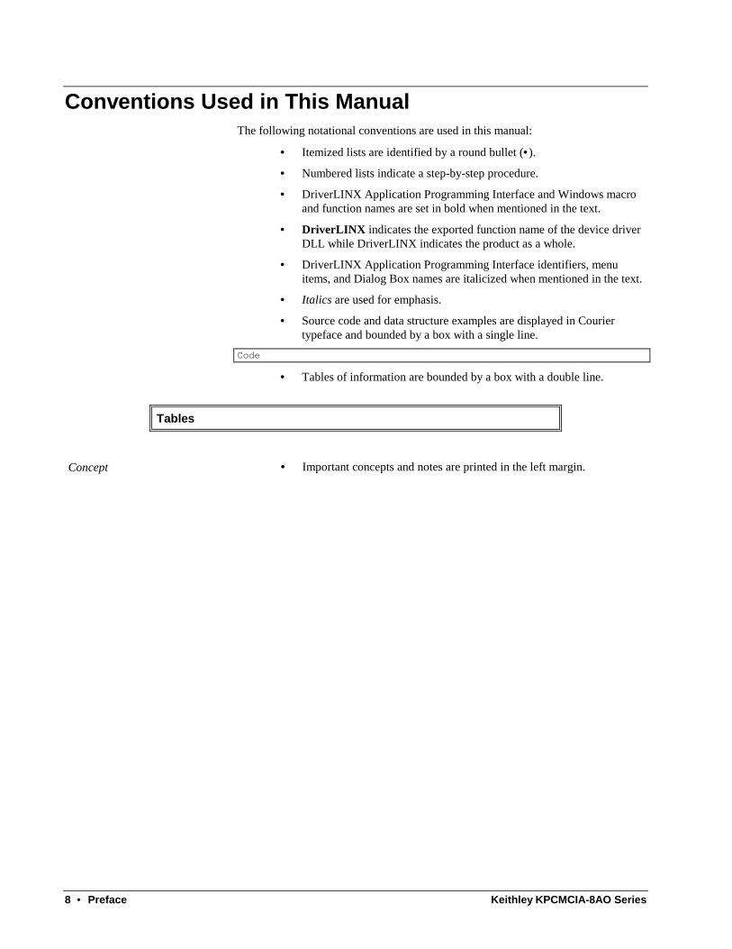
Conventions Used in This Manual The following notational conventions are used in this manual:
• Itemized lists are identified by a round bullet (•).
• Numbered lists indicate a step-by-step procedure.
• DriverLINX Application Programming Interface and Windows macro and function names are set in bold when mentioned in the text.
• DriverLINX indicates the exported function name of the device driver DLL while DriverLINX indicates the product as a whole.
• DriverLINX Application Programming Interface identifiers, menu items, and Dialog Box names are italicized when mentioned in the text.
• Italics are used for emphasis.
• Source code and data structure examples are displayed in Courier typeface and bounded by a box with a single line.
Code
• Tables of information are bounded by a box with a double line.
Tables
Concept • Important concepts and notes are printed in the left margin.

Keithley KPCMCIA-8AO Series Configuring the KPCMCIA-8AO Series • 9
Configuring the KPCMCIA-8AO Series
Introduction This manual explains the steps and special features that apply to Keithley’s KPCMCIA-8AO Series cards.
Installing and configuring DriverLINX for the Keithley KPCMCIA-8AO Series cards requires three steps:
1. To install your KPCMCIA-8AO hardware, read and follow the instructions in the hardware manual.
2. To install DriverLINX, follow the general procedure outlined in the “Read Me First” material on the installation CD.
3. To configure DriverLINX, use the DriverLINX Configuration Panel. Also see “Configure DriverLINX Device Dialog” on page 9 for configuration options specific to a Keithley KPCMCIA-8AO Series model.
Configure DriverLINX Device Dialog DriverLINX uses a standardized configuration protocol for all data-acquisition hardware. Even though Windows 95/98/Me automatically selects the hardware base address and interrupt channel for the KPCMCIA-8AO Series, you must still follow the configuration process to assign a DriverLINX Logical Device number to a specific KPCMCIA-8AO Series model in your computer.
When you activate the Setup… button in the DriverLINX Configuration Panel, DriverLINX displays the Configure DriverLINX Device dialog. The following sections describe your choices for configuring DriverLINX to work with a Keithley KPCMCIA-8AO Series model.

10 • Configuring the KPCMCIA-8AO Series Keithley KPCMCIA-8AO Series

Keithley KPCMCIA-8AO Series Configuring the KPCMCIA-8AO Series • 11
Device Subsystem Page
Note: The Configure DriverLINX Device dialog appears differently under different versions of Windows.
Use the Device subsystem page to tell DriverLINX the model name and address of your KPCMCIA-8AO Series card.
Vendor
The Vendor property displays “Keithley Instruments, Inc.” It is a read-only property.
Device
The Device property designates the Logical Device you are configuring. It is a read-only property. To change it, first save (OK) or quit (Cancel) the current configuration. Then select or create a new Logical Device using the DriverLINX Configuration Panel.
Model
The Model property selects the hardware model of the card you’re configuring.
All cards in this series support eight differential analog output channels and one 8-bit digital input/output port.
Windows 95/98/Me/2000 For Windows 95/98/Me/2000, Model is a read-only property—DriverLINX selects the next unconfigured card. To configure a different card, first save (OK) the current configuration. Then insert the appropriate card and select or create a new Logical Device using the DriverLINX Configuration Panel.
Windows NT For Windows NT, select one of the following models:
Model Resolution 8AO Channels
KPCMCIA-8AOB 12 bits 8 Bipolar (-5 - +5 V)
KPCMCIA-8AOU 12 bits 8 Unipolar (0 - 5 V)
12 • Configuring the KPCMCIA-8AO Series Keithley KPCMCIA-8AO Series
Address
Windows 95/98/Me/2000 Windows 95/98/Me/2000 automatically selects an appropriate address and ignores this property.
Windows NT The Address property selects the I/O port address for the card. The default address used by DriverLINX is 768 decimal or 0x300 hex. If you have another peripheral card at the same address, you will have to select a free range of 8 addresses.
Detect
The Detect property enables and disables DriverLINX’s hardware detection and testing algorithms. For maximum system reliability, always leave this check box marked.
Calibrate
The Calibrate property enables and disables hardware auto-calibration. For best accuracy, always leave this check box marked.
Special…
The Special… button displays a dialog for configuring any special, hardware-specific settings. For the KPCMCIA-8AO series, Logical Device configuration does not require any special settings so DriverLINX disables the Special… button.
Keithley KPCMCIA-8AO Series Configuring the KPCMCIA-8AO Series • 13
Analog Output Subsystem Page
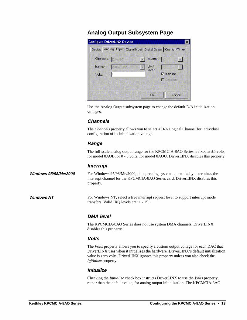
Use the Analog Output subsystem page to change the default D/A initialization voltages.
Channels
The Channels property allows you to select a D/A Logical Channel for individual configuration of its initialization voltage.
Range
The full-scale analog output range for the KPCMCIA-8AO Series is fixed at ±5 volts, for model 8AOB, or 0 - 5 volts, for model 8AOU. DriverLINX disables this property.
Interrupt
Windows 95/98/Me/2000 For Windows 95/98/Me/2000, the operating system automatically determines the interrupt channel for the KPCMCIA-8AO Series card. DriverLINX disables this property.
Windows NT For Windows NT, select a free interrupt request level to support interrupt mode transfers. Valid IRQ levels are: 1 - 15.
DMA level
The KPCMCIA-8AO Series does not use system DMA channels. DriverLINX disables this property.
Volts
The Volts property allows you to specify a custom output voltage for each DAC that DriverLINX uses when it initializes the hardware. DriverLINX’s default initialization value is zero volts. DriverLINX ignores this property unless you also check the Initialize property.
Initialize
Checking the Initialize check box instructs DriverLINX to use the Volts property, rather than the default value, for analog output initialization. The KPCMCIA-8AO

14 • Configuring the KPCMCIA-8AO Series Keithley KPCMCIA-8AO Series
Series does not support this feature. The hardware initializes all analog outputs to zero volts upon power up.
Calibrate
The Calibrate property enables and disables hardware auto-calibration. DriverLINX disables this property as the KPCMCIA-8AO Series DACs don’t support auto-calibration.
Keithley KPCMCIA-8AO Series Configuring the KPCMCIA-8AO Series • 15
Digital Input Subsystem Page
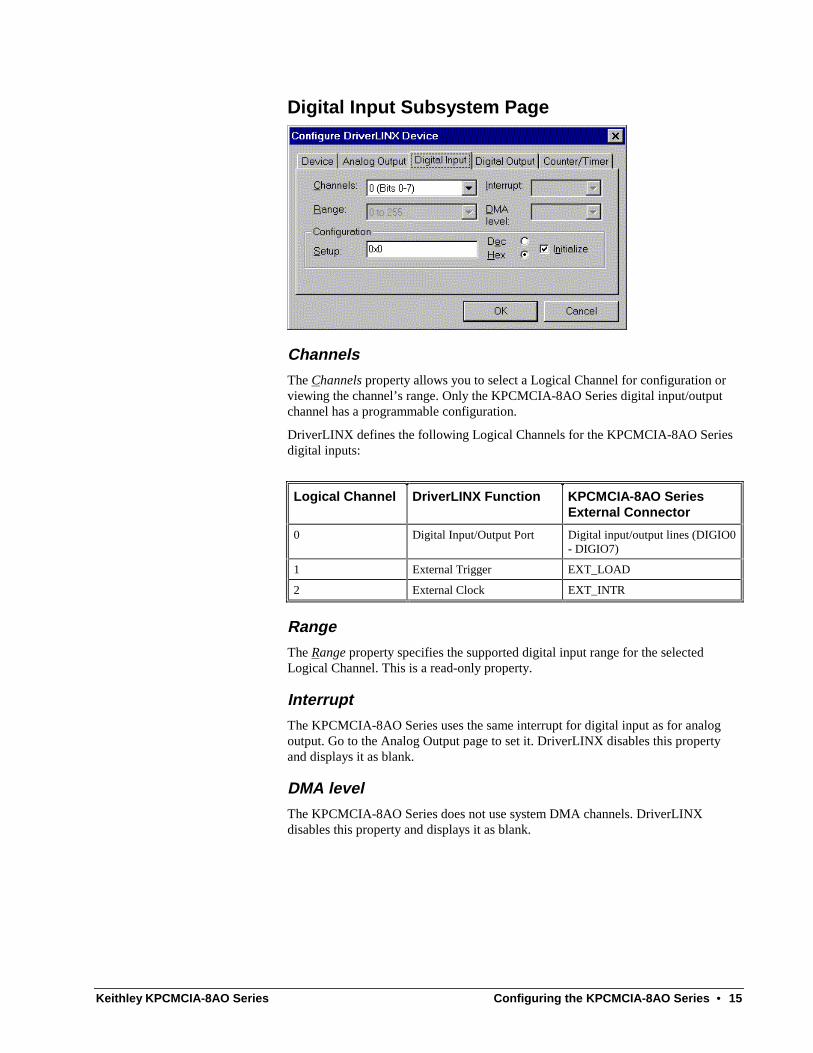
Channels
The Channels property allows you to select a Logical Channel for configuration or viewing the channel’s range. Only the KPCMCIA-8AO Series digital input/output channel has a programmable configuration.
DriverLINX defines the following Logical Channels for the KPCMCIA-8AO Series digital inputs:
Logical Channel DriverLINX Function KPCMCIA-8AO Series External Connector
0 Digital Input/Output Port Digital input/output lines (DIGIO0 - DIGIO7)
1 External Trigger EXT_LOAD
2 External Clock EXT_INTR
Range
The Range property specifies the supported digital input range for the selected Logical Channel. This is a read-only property.
Interrupt
The KPCMCIA-8AO Series uses the same interrupt for digital input as for analog output. Go to the Analog Output page to set it. DriverLINX disables this property and displays it as blank.
DMA level
The KPCMCIA-8AO Series does not use system DMA channels. DriverLINX disables this property and displays it as blank.
16 • Configuring the KPCMCIA-8AO Series Keithley KPCMCIA-8AO Series
Configuration Setup
Use caution when configuring and connecting lines to the digital I/O port. Connecting an input line to an output port, or vice versa, could damage the hardware.
The Configuration Setup property specifies the hardware configuration of the digital I/O port. The KPCMCIA-8AO Series allows configuring each line of the 8-bit I/O port for either input or output.
DriverLINX supports two methods for configuring a digital I/O port. The simplified method configures the whole port, while the advanced method allows you to configure groups of digital I/O lines.
Simplified Digital I/O Port Configuration
For simplified configuration, enter one of the following values for the Setup property to configure the entire port:
• 1—configures all lines in the port as input, or
• 0—configures all lines in the port as output.
Advanced Digital I/O Port Configuration
With advanced configuration, you can divide the port into groups of 1, 2, 4 or 8 lines and configure each group separately. The following table describes each grouping. Choose whichever grouping is most convenient.
Grouping Number of Lines in Each Group
Number of Groups in the Port
Byte 8 1
Nibble 4 2
Half-Nibble 2 4
Bit 1 8
For advanced configuration, the Setup property value has two variable-sized components:
• Direction Field—consists of a bit for each group in the port. Each bit indicates the input/output direction of the lines in the group. The least-significant bit configures the first group. High-order bits to the left configure subsequent groups.
For each bit, enter one of the following values to configure the group:
• 1—configures all lines in the group as input, or
• 0—configures all lines in the group as output.
• Group Size Field—consists of a binary 1 immediately to the left of the Direction field. This allows the position of the Setup property’s leftmost 1 to indicate the start of the Direction field.

Keithley KPCMCIA-8AO Series Configuring the KPCMCIA-8AO Series • 17
The following diagrams show the format of the Setup property for each grouping. All formats have the Group Size field in the high-order bits and the Direction field in the low-order bits.
Byte-Sized Groups
1
MSB LSB
• Direction Field—has one bit to configure the single byte-sized group
• Group Size Field—has a value of 0x2 (hexadecimal) or 2 (decimal)
Nibble-Sized Groups
1
MSB LSB
• Direction Field—has two bits to configure the two nibble-sized groups
• Group Size Field—has a value of 0x4 (hexadecimal) or 4 (decimal)
Half Nibble-Sized Groups
1
MSB LSB
• Direction Field—has four bits to configure the four half nibble-sized groups
• Group Size Field—has a value of 0x10 (hexadecimal) or 16 (decimal)
Bit-Sized Groups
1
MSB LSB
• Direction Field—has eight bits to configure the eight bit-sized groups
• Group Size Field—has a value of 0x100 (hexadecimal) or 512 (decimal)

18 • Configuring the KPCMCIA-8AO Series Keithley KPCMCIA-8AO Series
Advanced Configuration Example:
This example shows how to configure the port in nibbles. It configures the first nibble as output and the second as input.
1. Choose the Nibble-Sized format and fill in the Direction field, right-to-left, as follows:
0—to configure the first nibble as output
1—to configure the second nibble as input
1 1 0
2. Calculate the hexadecimal or decimal value:
0x4 + 0x2 + 0x0 = 0x6
4 + 2 + 0 = 6
3. Then, enter 0x6 (hexadecimal) or 6 (decimal) for the Setup property.
Initialize
Checking the Initialize check box instructs DriverLINX to use the Configuration Setup property to configure the digital I/O ports. Check Initialize to put the configuration setup into effect.
Dec
This check box converts the Configuration Setup property to decimal.
Hex
This check box converts the Configuration Setup property to hexadecimal.
Keithley KPCMCIA-8AO Series Configuring the KPCMCIA-8AO Series • 19
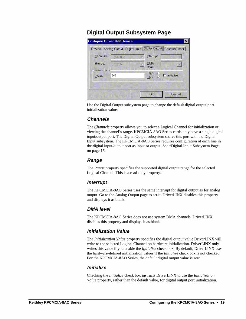
Digital Output Subsystem Page
Use the Digital Output subsystem page to change the default digital output port initialization values.
Channels
The Channels property allows you to select a Logical Channel for initialization or viewing the channel’s range. KPCMCIA-8AO Series cards only have a single digital input/output port. The Digital Output subsystem shares this port with the Digital Input subsystem. The KPCMCIA-8AO Series requires configuration of each line in the digital input/output port as input or output. See “Digital Input Subsystem Page” on page 15.
Range
The Range property specifies the supported digital output range for the selected Logical Channel. This is a read-only property.
Interrupt
The KPCMCIA-8AO Series uses the same interrupt for digital output as for analog output. Go to the Analog Output page to set it. DriverLINX disables this property and displays it as blank.
DMA level
The KPCMCIA-8AO Series does not use system DMA channels. DriverLINX disables this property and displays it as blank.
Initialization Value
The Initialization Value property specifies the digital output value DriverLINX will write to the selected Logical Channel on hardware initialization. DriverLINX only writes this value if you enable the Initialize check box. By default, DriverLINX uses the hardware-defined initialization values if the Initialize check box is not checked. For the KPCMCIA-8AO Series, the default digital output value is zero.
Initialize
Checking the Initialize check box instructs DriverLINX to use the Initialization Value property, rather than the default value, for digital output port initialization.

20 • Configuring the KPCMCIA-8AO Series Keithley KPCMCIA-8AO Series
Dec
This check box converts the Initialization Value property to decimal.
Hex
This check box converts the Initialization Value property to hexadecimal.
Keithley KPCMCIA-8AO Series Configuring the KPCMCIA-8AO Series • 21
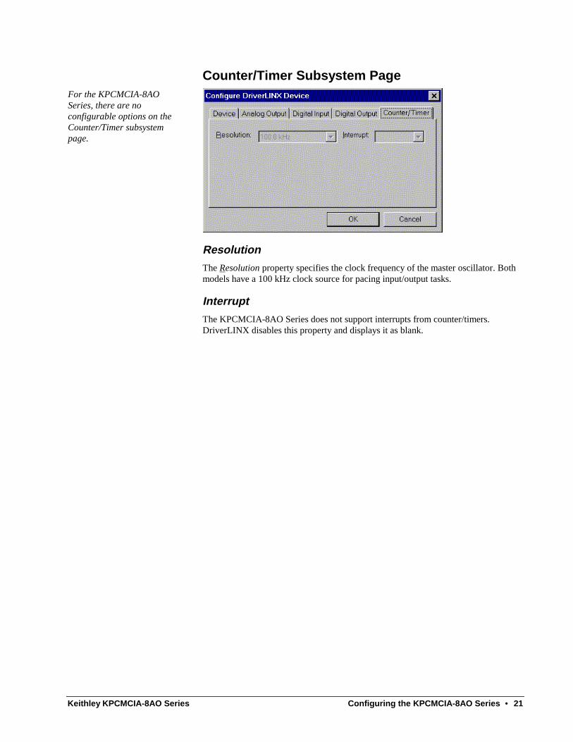
Counter/Timer Subsystem Page For the KPCMCIA-8AO Series, there are no configurable options on the Counter/Timer subsystem page.
Resolution
The Resolution property specifies the clock frequency of the master oscillator. Both models have a 100 kHz clock source for pacing input/output tasks.
Interrupt
The KPCMCIA-8AO Series does not support interrupts from counter/timers. DriverLINX disables this property and displays it as blank.


Keithley KPCMCIA-8AO Series Using the KPCMCIA-8AO Series with DriverLINX • 23
Using the KPCMCIA-8AO Series with DriverLINX
Introduction This chapter shows you how to set up and use KPCMCIA-8AO Series hardware features with DriverLINX. The descriptions here use the Edit Service Request dialogs for language and API independence. For the correct syntax with the language you’re using, please see the DriverLINX Technical Reference Manuals. For DriverLINX examples in your programming language, please see the source code examples in the subdirectories of your DriverLINX installation directory or on the original Distribution Media.
DriverLINX Hardware Model for KPCMCIA-8AO Series By design DriverLINX provides a portable, hardware-independent API for data-acquisition boards while still allowing applications to access unique or proprietary hardware features of specific products. To achieve this goal, DriverLINX maps a hardware-independent, or abstract, data-acquisition model onto KPCMCIA-8AO Series hardware capabilities.
The following sections describe how DriverLINX implements KPCMCIA-8AO Series hardware features as Subsystems, Modes, Operations, Events, Logical Channels, Buffers, and Messages.
DriverLINX Subsystems The KPCMCIA-8AO Series supports five of DriverLINX’s six Logical Subsystems:
1. Device—refers to a KPCMCIA-8AO model as a whole.
2. Analog Input—refers to the analog input channels, clocks, and control signals. The KPCMCIA-8AO Series does not support analog input.
3. Analog Output—refers to the analog output channels, clocks, and control signals.
4. Digital Input—refers to the 8-bit digital input/output port as well as 1-bit digital input (TTL) control signals, such as EXT_INTR, etc.

24 • Using the KPCMCIA-8AO Series with DriverLINX Keithley KPCMCIA-8AO Series
5. Digital Output—refers to the 8-bit digital input/output port.
6. Counter/Timer—refers to the internal clock channel for pacing input/output tasks.
DriverLINX Modes Applications use modes in Service Requests to advise DriverLINX on their preferred hardware data transfer technique. The DriverLINX modes fall into two general classes:
• Foreground or synchronous modes. The calling application doesn’t regain control until DriverLINX completes the Service Request. DriverLINX supports this mode for simple, single value I/O operations or software housekeeping functions that DriverLINX can complete without a significant delay.
• Background or asynchronous modes. The calling application regains control as soon as DriverLINX initiates the task. The calling application must synchronize with the data-acquisition task using status polling or DriverLINX’s messages (preferred). DriverLINX supports this mode for buffered data transfers or for commands that require a significant time to complete.
DriverLINX supports three of the four modes with the KPCMCIA-8AO Series for its commands (Service Requests).
• Polled Mode—This is a foreground or synchronous operation. DriverLINX supports this mode for simple, single-value I/O operations that the data-acquisition card can complete without significant delay.
• Interrupt Mode—This is a background or asynchronous operation. DriverLINX transfers data between the computer’s memory and the data-acquisition card using hardware interrupts and programmed I/O transfers.
• DMA Mode—This is a background or asynchronous operation. DriverLINX transfers data between the computer’s memory and the data-acquisition card using memory bus transfers. The KPCMCIA-8AO Series does not support this transfer mode.
• Other Mode—This is a foreground or synchronous operation. DriverLINX supports this mode for initialization, configuration, calibration, data conversion, and timebase operations.
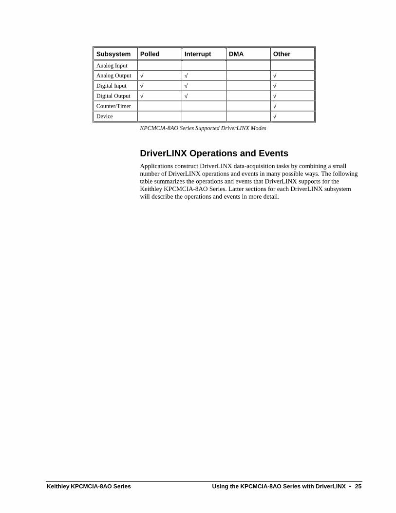
The following table summarizes the data acquisition modes that DriverLINX supports for each subsystem with the Keithley KPCMCIA-8AO Series.
Keithley KPCMCIA-8AO Series Using the KPCMCIA-8AO Series with DriverLINX • 25
Subsystem Polled Interrupt DMA Other
Analog Input
Analog Output √ √ √
Digital Input √ √ √
Digital Output √ √ √
Counter/Timer √
Device √
KPCMCIA-8AO Series Supported DriverLINX Modes
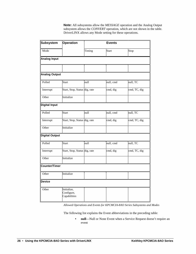
DriverLINX Operations and Events Applications construct DriverLINX data-acquisition tasks by combining a small number of DriverLINX operations and events in many possible ways. The following table summarizes the operations and events that DriverLINX supports for the Keithley KPCMCIA-8AO Series. Latter sections for each DriverLINX subsystem will describe the operations and events in more detail.
26 • Using the KPCMCIA-8AO Series with DriverLINX Keithley KPCMCIA-8AO Series
Note: All subsystems allow the MESSAGE operation and the Analog Output subsystem allows the CONVERT operation, which are not shown in the table. DriverLINX allows any Mode setting for these operations.
Subsystem Operation Events
Mode Timing Start Stop
Analog Input
Analog Output
Polled Start null null, cmd null, TC
Interrupt Start, Stop, Status dig, rate cmd, dig cmd, TC, dig
Other Initialize
Digital Input
Polled Start null null, cmd null, TC
Interrupt Start, Stop, Status dig, rate cmd, dig cmd, TC, dig
Other Initialize
Digital Output
Polled Start null null, cmd null, TC
Interrupt Start, Stop, Status dig, rate cmd, dig cmd, TC, dig
Other Initialize
Counter/Timer
Other Initialize
Device
Other Initialize, Configure, Capabilities
Allowed Operations and Events for KPCMCIA-8AO Series Subsystems and Modes
The following list explains the Event abbreviations in the preceding table:
• null—Null or None Event when a Service Request doesn’t require an event

Keithley KPCMCIA-8AO Series Using the KPCMCIA-8AO Series with DriverLINX • 27
• cmd—Command Event when DriverLINX starts or stops a task on software command
• TC—Terminal Count Event when DriverLINX processes all data buffers once
• rate—Rate Event specifies how DriverLINX paces or clocks data transfer
• dig—Digital Event specifies a trigger, clock, or other control signal to pace, start, or stop a task
Logical Channels DriverLINX designates the individually addressable hardware channels for each subsystem as “Logical Channels”. Generally, the zero-based Logical Channel numbering sequence closely follows the hardware channel numbering scheme.
In some cases, however, DriverLINX assigns Logical Channel numbers to hardware features that users don’t commonly think of as “channels”. For instance, DriverLINX commonly models external hardware clock input lines, external hardware trigger input lines, and external interrupt inputs as 1-bit digital Logical Channels. In other cases, DriverLINX models subsystem-specific features, such as internal pacer clocks, as members of a more general purpose set of counter/timer channels.
For how DriverLINX assigns Logical Channel numbers, see the notes for each supported subsystem.
Buffers Applications usually use data buffers to exchange data between the application and the data-acquisition hardware. When using data buffers, please observe the following points about DriverLINX’s data buffers:
• DriverLINX supports data-acquisition tasks with 1 to 255 data buffers per task.
• DriverLINX imposes no size limits on a single buffer, although the operating system or some hardware products may have size restrictions.
• User applications must allow DriverLINX to allocate all data buffers to guarantee application portability to different hardware and operating systems and to insure that the hardware can physically access the buffer memory.
• User applications usually don’t have concurrent or immediate access to the in-use data buffer while DriverLINX is executing a data-acquisition task.
28 • Using the KPCMCIA-8AO Series with DriverLINX Keithley KPCMCIA-8AO Series
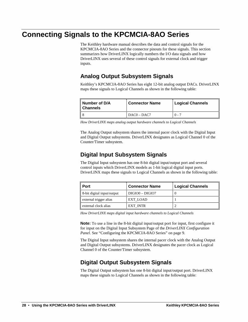
Connecting Signals to the KPCMCIA-8AO Series The Keithley hardware manual describes the data and control signals for the KPCMCIA-8AO Series and the connector pinouts for these signals. This section summarizes how DriverLINX logically numbers the I/O data signals and how DriverLINX uses several of these control signals for external clock and trigger inputs.
Analog Output Subsystem Signals Keithley’s KPCMCIA-8AO Series has eight 12-bit analog output DACs. DriverLINX maps these signals to Logical Channels as shown in the following table:
Number of D/A Channels
Connector Name Logical Channels
8 DAC0 – DAC7 0 - 7
How DriverLINX maps analog output hardware channels to Logical Channels
The Analog Output subsystem shares the internal pacer clock with the Digital Input and Digital Output subsystems. DriverLINX designates as Logical Channel 0 of the Counter/Timer subsystem.
Digital Input Subsystem Signals The Digital Input subsystem has one 8-bit digital input/output port and several control inputs which DriverLINX models as 1-bit logical digital input ports. DriverLINX maps these signals to Logical Channels as shown in the following table:
Port Connector Name Logical Channels
8-bit digital input/output DIGIO0 – DIGIO7 0
external trigger alias EXT_LOAD 1
external clock alias EXT_INTR 2
How DriverLINX maps digital input hardware channels to Logical Channels
Note: To use a line in the 8-bit digital input/output port for input, first configure it for input on the Digital Input Subsystem Page of the DriverLINX Configuration Panel. See “Configuring the KPCMCIA-8AO Series” on page 9.
The Digital Input subsystem shares the internal pacer clock with the Analog Output and Digital Output subsystems. DriverLINX designates the pacer clock as Logical Channel 0 of the Counter/Timer subsystem.
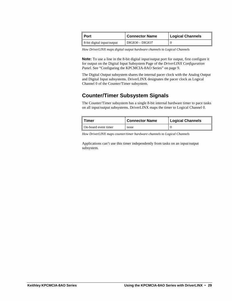
Digital Output Subsystem Signals The Digital Output subsystem has one 8-bit digital input/output port. DriverLINX maps these signals to Logical Channels as shown in the following table:
Keithley KPCMCIA-8AO Series Using the KPCMCIA-8AO Series with DriverLINX • 29
Port Connector Name Logical Channels
8-bit digital input/output DIGIO0 – DIGIO7 0
How DriverLINX maps digital output hardware channels to Logical Channels
Note: To use a line in the 8-bit digital input/output port for output, first configure it for output on the Digital Input Subsystem Page of the DriverLINX Configuration Panel. See “Configuring the KPCMCIA-8AO Series” on page 9.
The Digital Output subsystem shares the internal pacer clock with the Analog Output and Digital Input subsystems. DriverLINX designates the pacer clock as Logical Channel 0 of the Counter/Timer subsystem.
Counter/Timer Subsystem Signals The Counter/Timer subsystem has a single 8-bit internal hardware timer to pace tasks on all input/output subsystems. DriverLINX maps the timer to Logical Channel 0.
Timer Connector Name Logical Channels
On-board event timer none 0
How DriverLINX maps counter/timer hardware channels to Logical Channels
Applications can’t use this timer independently from tasks on an input/output subsystem.

30 • Using the KPCMCIA-8AO Series with DriverLINX Keithley KPCMCIA-8AO Series
Device Subsystem The following sections describe how DriverLINX implements Device Subsystem features for the KPCMCIA-8AO Series.
Device Modes The Device Subsystem only supports DriverLINX’s Other mode for all operations.
Device Operations The KPCMCIA-8AO Series Device Subsystem supports the following DriverLINX operations:
If another process is using the same data-acquisition card, DriverLINX will prevent Device Initialization from interfering with another process’s data-acquisition tasks.
• Initialize—DriverLINX aborts all data-acquisition tasks for every subsystem controlled by the current process. DriverLINX then performs an initialization for each supported subsystem.
• Configure—DriverLINX displays the Configure DriverLINX Device dialog for the current Logical Device. Please use the DriverLINX Configuration Panel rather than this operation to configure DriverLINX.
• Capabilities—DriverLINX provides hardware-specific and configuration information in the form of a Logical Device Descriptor database.

Keithley KPCMCIA-8AO Series Using the KPCMCIA-8AO Series with DriverLINX • 31
Analog Output Subsystem The following sections describe how DriverLINX implements Analog Output Subsystem features for the KPCMCIA-8AO Series.
Analog Output Modes The Analog Output Subsystem supports the following modes:
• Polled—For single value analog output samples.
• Interrupt—For buffered transfers using programmed I/O.
• Other—For subsystem initialization and data conversion.
Analog Output Operations The KPCMCIA-8AO Series Analog Output Subsystem supports the following DriverLINX operations:
• Initialize—aborts any active DMA or interrupt data-acquisition tasks and stops the clock. DriverLINX prevents one application process from interfering with another process’s data-acquisition tasks.
• Start—initiates a data-acquisition task using the Mode, Timing, Start, and Stop Events, the Logical Channels, and the Buffers the application specified in the Service Request.
• Status—reports the buffer position of the next sample that DriverLINX will write into a buffer.
• Stop—terminates an analog output data-acquisition task.
• Message—DriverLINX displays a pop-up dialog box for the user containing the text for the current DriverLINX error message.
Analog Output Initialization
By default, the Analog Output subsystem loads zero into both D/A channels forcing the initial output voltage to zero.
Analog Output Timing Events Timing Events specify how the hardware paces or clocks analog output samples. DriverLINX uses the Timing Event to program when the KPCMCIA-8AO Series writes the next analog output sample to the DACs.
The KPCMCIA-8AO Series supports the following Timing Events:
• None—Output requires no pacing as DriverLINX is writing only a single value.
• Rate—The KPCMCIA-8AO Series supports only fixed rate analog output using internal and external clocks.
• Digital—DriverLINX uses an external digital input signal to pace the output of each sample.
32 • Using the KPCMCIA-8AO Series with DriverLINX Keithley KPCMCIA-8AO Series
None or Null Event
The Null Event specifies that the task does not need a clock to determine when to write the next sample.
Rate Event
The KPCMCIA-8AO Series supports one type of Rate Event for analog output:
• Rate Generator—Generates a fixed rate clock with equal time intervals between tics.
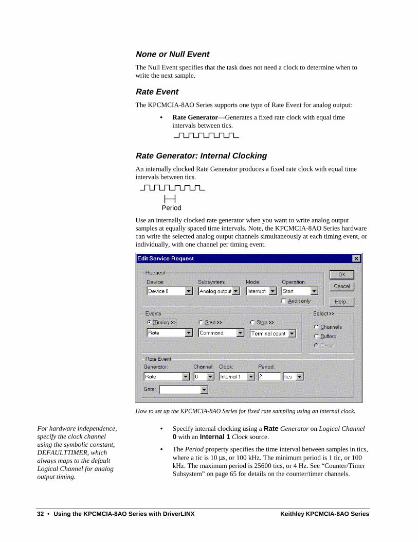
Rate Generator: Internal Clocking
An internally clocked Rate Generator produces a fixed rate clock with equal time intervals between tics.
Period
Use an internally clocked rate generator when you want to write analog output samples at equally spaced time intervals. Note, the KPCMCIA-8AO Series hardware can write the selected analog output channels simultaneously at each timing event, or individually, with one channel per timing event.
How to set up the KPCMCIA-8AO Series for fixed rate sampling using an internal clock.
For hardware independence, specify the clock channel using the symbolic constant, DEFAULTTIMER, which always maps to the default Logical Channel for analog output timing.
• Specify internal clocking using a Rate Generator on Logical Channel 0 with an Internal 1 Clock source.
• The Period property specifies the time interval between samples in tics, where a tic is 10 µs, or 100 kHz. The minimum period is 1 tic, or 100 kHz. The maximum period is 25600 tics, or 4 Hz. See “Counter/Timer Subsystem” on page 65 for details on the counter/timer channels.

Keithley KPCMCIA-8AO Series Using the KPCMCIA-8AO Series with DriverLINX • 33
Rate Generator: External Clocking
An externally clocked Rate Generator produces a rate clock with unknown time intervals between tics.
Period (ext clk)
Use an externally clocked rate generator when you want to synchronize analog output samples with a recurrent external signal. Note, the KPCMCIA-8AO Series hardware can write the selected analog output channels simultaneously at each timing event, or individually, with one channel per timing event.
How to set up the KPCMCIA-8AO Series for fixed rate sampling using an external clock.
BE SURE that the external clock source is TTL compatible, 0 V minimum to +5 V maximum!
• Specify external clocking using a Rate Generator on Logical Channel 0 with an External or External+ Clock source. External and External+ both specify sampling on the rising, or positive, edge of the external clock signal.
• Users should connect the external clock signal to the EXT_INTR line.
• The Period may be any value ≥ 1 tic, or 10 µs. The period value doesn’t affect the external clock frequency, but DriverLINX requires a valid hardware value in case the application requests a timebase operation and to optimize data transfer between the driver and the application.
Digital Event
DriverLINX supports Digital Events as aliases for externally clocked Rate Generators. Use this technique for compatibility with data-acquisition products that only support externally clock sources. Note, the KPCMCIA-8AO Series hardware can write the selected analog output channels simultaneously at each timing, or individually, with one channel per timing event.

34 • Using the KPCMCIA-8AO Series with DriverLINX Keithley KPCMCIA-8AO Series
How to set up the KPCMCIA-8AO Series for external rate sampling using a digital event.
Digital Timing Events contain mask, pattern, and match fields. The mask is logically AND with the digital input data on the Logical Channel and then compared against the pattern for a match/mismatch.
BE SURE that the external clock source is TTL compatible, 0 V minimum to +5 V maximum!
• Specify external clocking using Logical Channel 2. For hardware-independence, you can specify the hardware external trigger channel by the symbolic constant, DI_EXTCLK.
• Users should connect the external clock signal to the EXT_INTR line.
• Specify the Mask property as Bit 0 or 1 to indicate that DriverLINX should only compare a 1-bit digital input value against the Pattern property.
• Specify the Match property as Not Equals.
• Specify the Pattern property as 0 for a rising, or positive, edge clock (≠1), or 1 for a falling, or negative, edge clock (≠0).
Analog Output Start Events Start Events specify when the KPCMCIA-8AO Series hardware starts writing analog output data.
The KPCMCIA-8AO Series supports the following Start Events for analog output:
• None—Use this event when the DriverLINX operation doesn’t require a Start Event.
• Command—DriverLINX starts the task on software command, i.e., as soon as DriverLINX finishes programming the KPCMCIA-8AO hardware for the task.
• Digital—The KPCMCIA-8AO starts writing analog output samples when the hardware detects the digital Logical Channel input satisfies the digital condition specified in the Start Event.
Keithley KPCMCIA-8AO Series Using the KPCMCIA-8AO Series with DriverLINX • 35
None or Null Event
The Null Event specifies that the task does not need a Start Event to begin the task.
Command Event
The Command Event starts data acquisition as soon as DriverLINX has completed programming the KPCMCIA-8AO Series hardware with the task parameters.
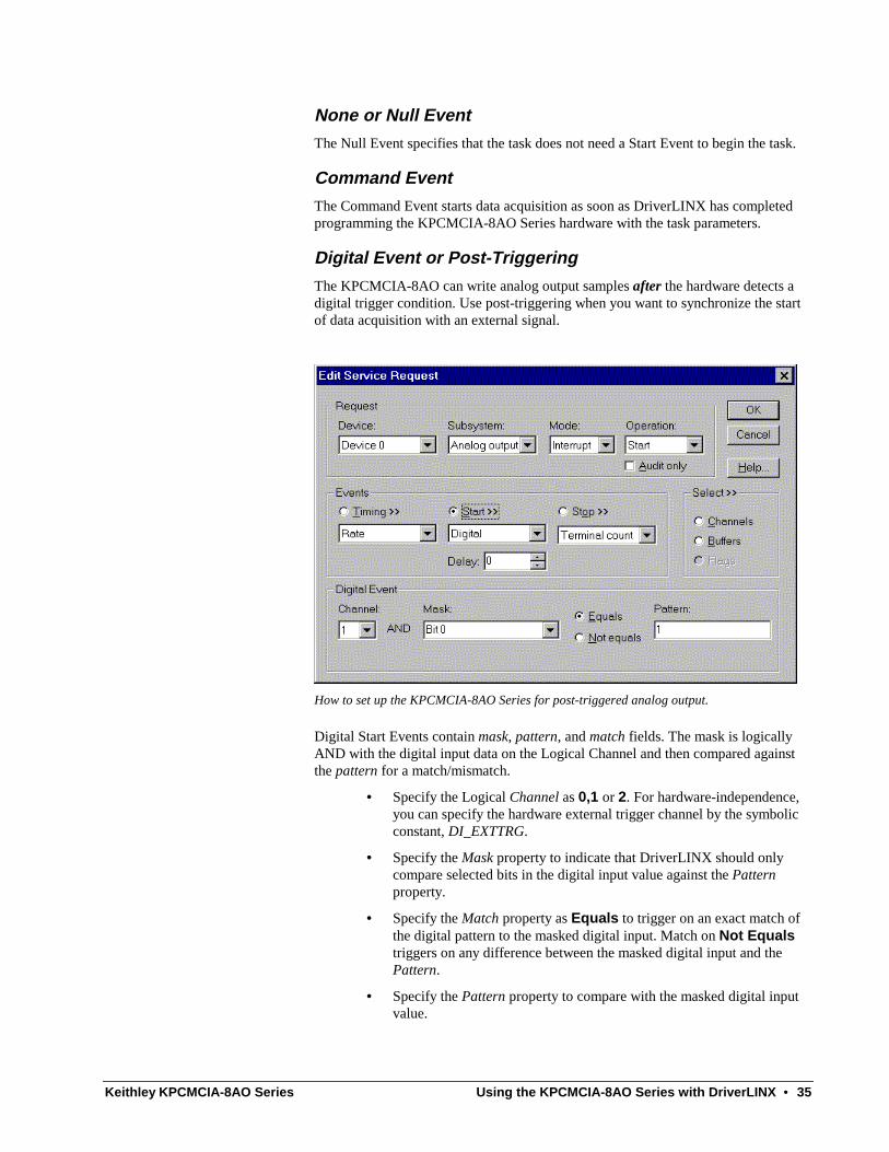
Digital Event or Post-Triggering
The KPCMCIA-8AO can write analog output samples after the hardware detects a digital trigger condition. Use post-triggering when you want to synchronize the start of data acquisition with an external signal.
How to set up the KPCMCIA-8AO Series for post-triggered analog output.
Digital Start Events contain mask, pattern, and match fields. The mask is logically AND with the digital input data on the Logical Channel and then compared against the pattern for a match/mismatch.
• Specify the Logical Channel as 0,1 or 2. For hardware-independence, you can specify the hardware external trigger channel by the symbolic constant, DI_EXTTRG.
• Specify the Mask property to indicate that DriverLINX should only compare selected bits in the digital input value against the Pattern property.
• Specify the Match property as Equals to trigger on an exact match of the digital pattern to the masked digital input. Match on Not Equals triggers on any difference between the masked digital input and the Pattern.
• Specify the Pattern property to compare with the masked digital input value.
36 • Using the KPCMCIA-8AO Series with DriverLINX Keithley KPCMCIA-8AO Series
• Specify the Delay property as any number of samples from 0 to 232-1.
Analog Output Stop Events Stop Events specify when the KPCMCIA-8AO Series hardware stops writing analog output data.
The KPCMCIA-8AO Series supports the following Stop Events for analog output:
• None—Use this event when the DriverLINX operation doesn’t require a Stop Event.
• Command—DriverLINX stops the task on software command, i.e., when the application issues a Service Request with a Stop operation.
• Terminal count—DriverLINX stops the task after the data-acquisition hardware has written all the data buffers once.
• Digital—The KPCMCIA-8AO stops the task when the hardware detects the digital Logical Channel input satisfies the digital condition specified in the Stop Event.
None or Null Event
The Null Event specifies that the task does not need a Stop Event to end the task.
Command Event
The Command Event stops data acquisition when the user application changes the Operation property in the Service Request to Stop and resubmits the Service Request to DriverLINX.
In stop-on-command mode, DriverLINX continuously cycles through all the data buffers, writing them to the DACs on the KPCMCIA-8AO Series.
Terminal Count Event
The Terminal Count Event stops data acquisition after DriverLINX has written the analog output data in all the data buffers once. Use terminal count when you want to write a fixed amount of data.
Digital Event or Pre-Triggering
The KPCMCIA-8AO can write analog output samples until the hardware detects a digital trigger condition. Use pre-triggering when you want to synchronize the end of data acquisition with an external signal.

Keithley KPCMCIA-8AO Series Using the KPCMCIA-8AO Series with DriverLINX • 37
How to set up the KPCMCIA-8AO Series for pre-triggered digital input.
Digital Stop Events contain mask, pattern, and match fields. The mask is logically AND with the digital input data on the Logical Channel and then compared against the pattern for a match/mismatch.
• Specify the Logical Channel as 0,1 or 2. For hardware-independence, you can specify the hardware external trigger channel by the symbolic constant, DI_EXTTRG.
• Specify the Mask property to indicate that DriverLINX should only compare selected bits in the digital input value against the Pattern property.
• Specify the Match property as Equals to trigger on an exact match of the digital pattern to the masked digital input. Match on Not Equals triggers on any difference between the masked digital input and the Pattern.
• Specify the Pattern property to compare with the masked digital input value.
• Specify the Delay property as any number of samples from 0 to 232-1.
Analog Output Channels The KPCMCIA-8AO Series allows applications to specify the analog channels using three techniques:
• Start Channel—Write analog data to a single channel.
• Start/Stop Channel Range—Write analog data to a consecutive range of channels.
• Channel List—Write analog data to a list of channels.
38 • Using the KPCMCIA-8AO Series with DriverLINX Keithley KPCMCIA-8AO Series
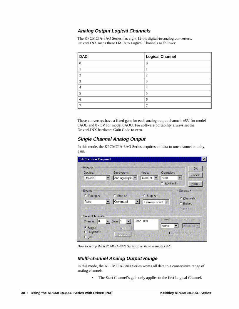
Analog Output Logical Channels
The KPCMCIA-8AO Series has eight 12-bit digital-to-analog converters. DriverLINX maps these DACs to Logical Channels as follows:
DAC Logical Channel
0 0
1 1
2 2
3 3
4 4
5 5
6 6
7 7
These converters have a fixed gain for each analog output channel; ±5V for model 8AOB and 0 - 5V for model 8AOU. For software portability always set the DriverLINX hardware Gain Code to zero.
Single Channel Analog Output
In this mode, the KPCMCIA-8AO Series acquires all data to one channel at unity gain.
How to set up the KPCMCIA-8AO Series to write to a single DAC
Multi-channel Analog Output Range
In this mode, the KPCMCIA-8AO Series writes all data to a consecutive range of analog channels.
• The Start Channel’s gain only applies to the first Logical Channel.

Keithley KPCMCIA-8AO Series Using the KPCMCIA-8AO Series with DriverLINX • 39
• DriverLINX uses the Stop Channel’s gain for all the other analog channels in the range.
• If the Start Channel is greater than the Stop Channel, the channel sequence is [Start Channel, …, last Channel, 0, …, Stop Channel], where last Channel is the highest numbered Logical Channel for the KPCMCIA-8AO Series model the application is using.
• The KPCMCIA-8AO Series can optionally output to all DACs in the range simultaneously, or write to one DAC in the range at each timing event.
How to set up the KPCMCIA-8AO Series using a start/stop range to write to multiple DACs
Multi-channel Analog Output List
In this mode, the KPCMCIA-8AO Series acquires all data to a random list of analog channels.
• The channel-gain list may contain channels in any order but only with unity gain. In simultaneous mode, the list may not repeat the same channel.
• The KPCMCIA-8AO Series can optionally output to all DACs in the list simultaneously, or write to one DAC in the list at each timing event.

40 • Using the KPCMCIA-8AO Series with DriverLINX Keithley KPCMCIA-8AO Series
How to set up the KPCMCIA-8AO Series using a channel list to write to multiple DACs
Analog Output Buffers DriverLINX supports both single-value analog output and buffered analog output.
• For single-value output, specify the Number of buffers as 0 and the buffer size as 0.
• For buffered output, specify the Number of buffers from 1 to 256 and the buffer size as desired.
How to set up the KPCMCIA-8AO Series for analog output using buffers
Keithley KPCMCIA-8AO Series Using the KPCMCIA-8AO Series with DriverLINX • 41
For example, 500 samples/2 channels = 250 is ok, but 503 samples/2 channels = 251.5 is incorrect.
An individual DriverLINX buffer may have any size as long as the buffer length holds an integral number of channel scans, i.e., the number of analog output channels you’re acquiring. This restriction enforces the requirement that all output channels have the same number of samples.
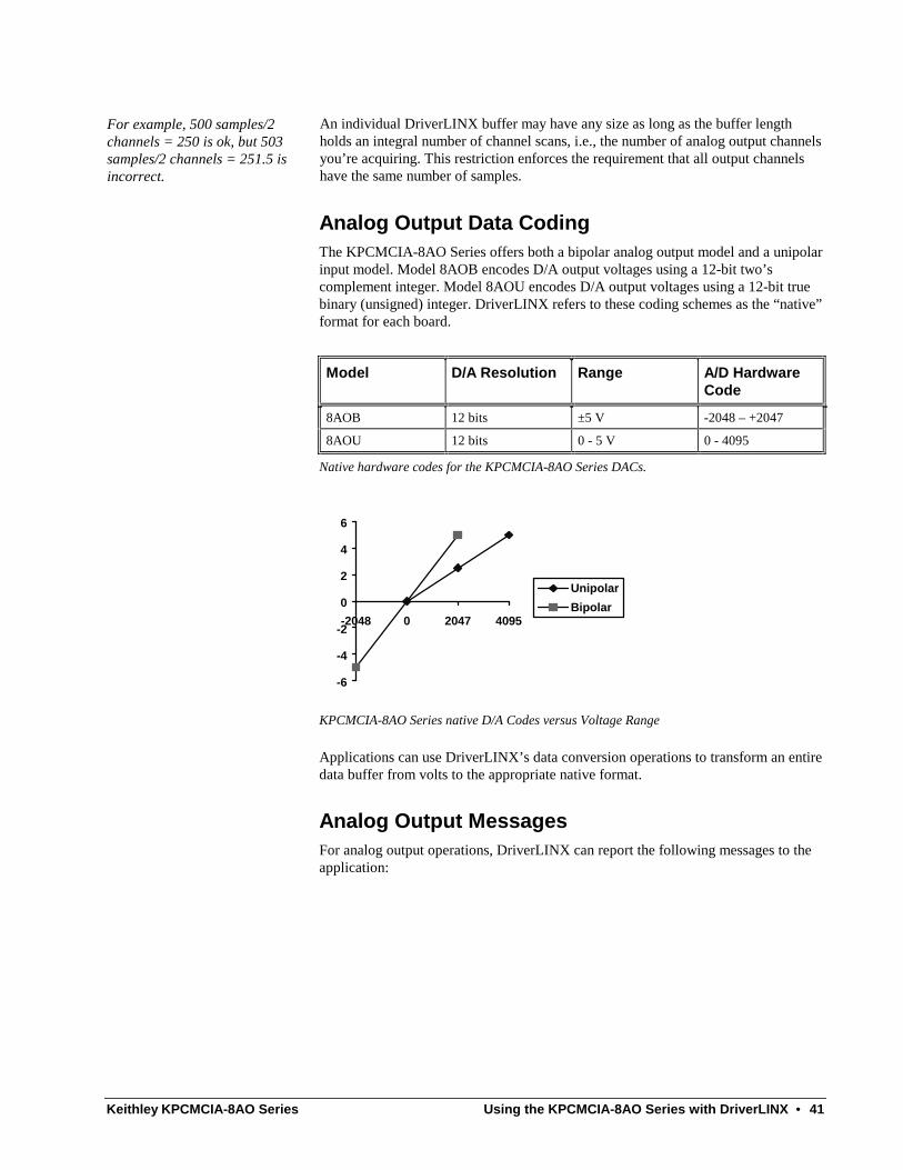
Analog Output Data Coding The KPCMCIA-8AO Series offers both a bipolar analog output model and a unipolar input model. Model 8AOB encodes D/A output voltages using a 12-bit two’s complement integer. Model 8AOU encodes D/A output voltages using a 12-bit true binary (unsigned) integer. DriverLINX refers to these coding schemes as the “native” format for each board.
Model D/A Resolution Range A/D Hardware Code
8AOB 12 bits ±5 V -2048 – +2047
8AOU 12 bits 0 - 5 V 0 - 4095
Native hardware codes for the KPCMCIA-8AO Series DACs.
-6
-4
-2
0
2
4
6
-2048 0 2047 4095
Unipolar
Bipolar
KPCMCIA-8AO Series native D/A Codes versus Voltage Range
Applications can use DriverLINX’s data conversion operations to transform an entire data buffer from volts to the appropriate native format.
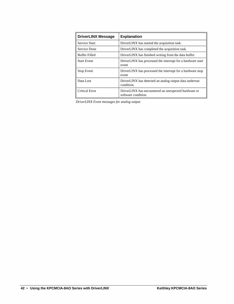
Analog Output Messages For analog output operations, DriverLINX can report the following messages to the application:
42 • Using the KPCMCIA-8AO Series with DriverLINX Keithley KPCMCIA-8AO Series
DriverLINX Message Explanation
Service Start DriverLINX has started the acquisition task.
Service Done DriverLINX has completed the acquisition task.
Buffer Filled DriverLINX has finished writing from the data buffer.
Start Event DriverLINX has processed the interrupt for a hardware start event
Stop Event DriverLINX has processed the interrupt for a hardware stop event
Data Lost DriverLINX has detected an analog output data underrun condition.
Critical Error DriverLINX has encountered an unexpected hardware or software condition.
DriverLINX Event messages for analog output

Keithley KPCMCIA-8AO Series Using the KPCMCIA-8AO Series with DriverLINX • 43
Digital Input Subsystem The following sections describe how DriverLINX implements Digital Input Subsystem features for the KPCMCIA-8AO Series.
Digital Input Modes The Digital Input Subsystem supports the following modes:
• Polled—For single value digital input samples.
• Interrupt—For buffered transfers using programmed I/O.
• Other—For subsystem initialization and data conversion.
Digital Input Operations The KPCMCIA-8AO Series Digital Input Subsystem supports the following DriverLINX operations:
• Initialize—aborts any active interrupt data-acquisition tasks and stops the clock. DriverLINX prevents one application process from interfering with another process’s data-acquisition tasks.
• Start—initiates a data-acquisition task using the Mode, Timing, Start, and Stop Events, the Logical Channels, and the Buffers the application specified in the Service Request.
• Status—reports the buffer position of the next sample that DriverLINX will read into a buffer.
• Stop—terminates a digital input data-acquisition task.
• Message—DriverLINX displays a pop-up dialog box for the user containing the text for the current DriverLINX error message.
Digital Port Configuration
The KPCMCIA-8AO Series has a shared digital input/output port that requires configuration before connecting signals. Therefore, DriverLINX does not allow the application to configure the KPCMCIA-8AO’s digital I/O port.
Note: To use a line in the 8-bit digital input/output port for output, first configure it for output on the Digital Input Subsystem Page of the DriverLINX Configuration Panel. See “Configuring the KPCMCIA-8AO Series” on page 9.
Digital Input Timing Events Timing Events specify how the hardware paces or clocks the reading of Digital Input samples. DriverLINX uses the Timing Event to program when the KPCMCIA-8AO Series reads the next digital input sample from the port.
The KPCMCIA-8AO Series supports the following Timing Events:
• None—Input requires no pacing as DriverLINX is reading only a single value.
• Rate—The KPCMCIA-8AO Series supports only fixed rate digital input using internal and external clocks.
44 • Using the KPCMCIA-8AO Series with DriverLINX Keithley KPCMCIA-8AO Series
• Digital—DriverLINX uses an external digital input signal to pace the acquisition of each sample.
None or Null Event
The Null Event specifies that the task does not need a clock to determine when to read the next sample.
Rate Event
The KPCMCIA-8AO Series supports one type of Rate Event for digital input:
• Rate Generator—Generates a fixed rate clock with equal time intervals between tics.
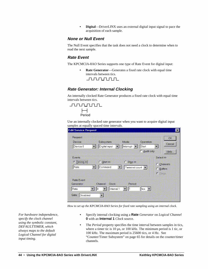
Rate Generator: Internal Clocking
An internally clocked Rate Generator produces a fixed rate clock with equal time intervals between tics.
Period Use an internally clocked rate generator when you want to acquire digital input samples at equally spaced time intervals.
How to set up the KPCMCIA-8AO Series for fixed rate sampling using an internal clock.
For hardware independence, specify the clock channel using the symbolic constant, DEFAULTTIMER, which always maps to the default Logical Channel for digital input timing.
• Specify internal clocking using a Rate Generator on Logical Channel 0 with an Internal 1 Clock source.
• The Period property specifies the time interval between samples in tics, where a timer tic is 10 µs, or 100 kHz. The minimum period is 1 tic, or 100 kHz. The maximum period is 25600 tics, or 4 Hz. See “Counter/Timer Subsystem” on page 65 for details on the counter/timer channels.

Keithley KPCMCIA-8AO Series Using the KPCMCIA-8AO Series with DriverLINX • 45
Rate Generator: External Clocking
An externally clocked Rate Generator produces a rate clock with unknown time intervals between tics.
Period (ext clk)
Use an externally clocked rate generator when you want to synchronize digital input samples with a recurrent external signal.
How to set up the KPCMCIA-8AO Series for fixed rate sampling using an external clock.
BE SURE that the external clock source is TTL compatible, 0 V minimum to +5 V maximum!
• Specify external clocking using a Rate Generator on Logical Channel 0 with an External or External+ Clock source. External and External+ both specify sampling on the rising, or positive, edge of the external clock signal.
• Users should connect the external clock signal to the EXT_INTR line.
• The Period may be any value ≥ 1 tic, or 10 µs. The period value doesn’t affect the external clock frequency, but DriverLINX requires a valid hardware value in case the application requests a timebase operation and to optimize data transfer between the driver and the application.
Digital Event
DriverLINX supports Digital Events as aliases for externally clocked Rate Generators. Use this technique for compatibility with data-acquisition products that only support externally clock sources.
46 • Using the KPCMCIA-8AO Series with DriverLINX Keithley KPCMCIA-8AO Series
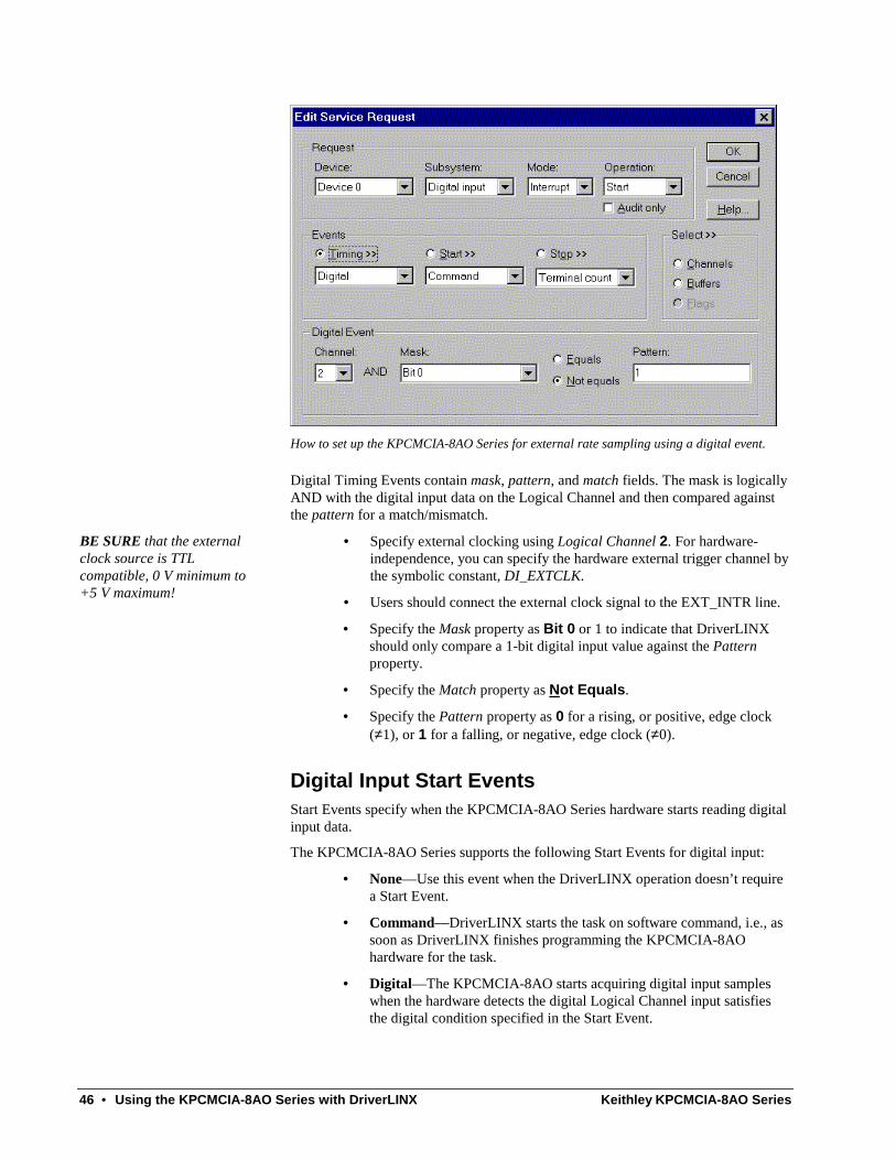
How to set up the KPCMCIA-8AO Series for external rate sampling using a digital event.
Digital Timing Events contain mask, pattern, and match fields. The mask is logically AND with the digital input data on the Logical Channel and then compared against the pattern for a match/mismatch.
BE SURE that the external clock source is TTL compatible, 0 V minimum to +5 V maximum!
• Specify external clocking using Logical Channel 2. For hardware-independence, you can specify the hardware external trigger channel by the symbolic constant, DI_EXTCLK.
• Users should connect the external clock signal to the EXT_INTR line.
• Specify the Mask property as Bit 0 or 1 to indicate that DriverLINX should only compare a 1-bit digital input value against the Pattern property.
• Specify the Match property as Not Equals.
• Specify the Pattern property as 0 for a rising, or positive, edge clock (≠1), or 1 for a falling, or negative, edge clock (≠0).
Digital Input Start Events Start Events specify when the KPCMCIA-8AO Series hardware starts reading digital input data.
The KPCMCIA-8AO Series supports the following Start Events for digital input:
• None—Use this event when the DriverLINX operation doesn’t require a Start Event.
• Command—DriverLINX starts the task on software command, i.e., as soon as DriverLINX finishes programming the KPCMCIA-8AO hardware for the task.
• Digital—The KPCMCIA-8AO starts acquiring digital input samples when the hardware detects the digital Logical Channel input satisfies the digital condition specified in the Start Event.

Keithley KPCMCIA-8AO Series Using the KPCMCIA-8AO Series with DriverLINX • 47
None or Null Event
The Null Event specifies that the task does not need a Start Event to begin the task.
Command Event
The Command Event starts data acquisition as soon as DriverLINX has completed programming the KPCMCIA-8AO Series hardware with the task parameters.
Digital Event or Post-Triggering
The KPCMCIA-8AO can acquire digital input samples after the hardware detects a digital trigger condition. Use post-triggering when you want to synchronize the start of data acquisition with an external signal.
How to set up the KPCMCIA-8AO Series for post-triggered digital input.
Digital Start Events contain mask, pattern, and match fields. The mask is logically AND with the digital input data on the Logical Channel and then compared against the pattern for a match/mismatch.
• Specify the Logical Channel as 0,1 or 2. For hardware-independence, you can specify the hardware external trigger channel by the symbolic constant, DI_EXTTRG.
• Specify the Mask property to indicate that DriverLINX should only compare selected bits in the digital input value against the Pattern property.
• Specify the Match property as Equals to trigger on an exact match of the digital pattern to the masked digital input. Match on Not Equals triggers on any difference between the masked digital input and the Pattern.
• Specify the Pattern property to compare with the masked digital input value.

48 • Using the KPCMCIA-8AO Series with DriverLINX Keithley KPCMCIA-8AO Series
• Specify the Delay property as any number of samples from 0 to 232-1.
Digital Input Stop Events Stop Events specify when the KPCMCIA-8AO Series hardware stops reading digital input data.
The KPCMCIA-8AO Series supports the following Stop Events for digital input:
• None—Use this event when the DriverLINX operation doesn’t require a Stop Event.
• Command—DriverLINX stops the task on software command, i.e., when the application issues a Service Request with a Stop operation.
• Terminal count—DriverLINX stops the task after the KPCMCIA-8AO Series hardware has filled all the data buffers once.
• Digital—The KPCMCIA-8AO stops the task when the hardware detects the digital Logical Channel input satisfies the digital condition specified in the Stop Event.
None or Null Event
The Null Event specifies that the task does not need a Stop Event to end the task.
Command Event
The Command Event stops data acquisition when the user application changes the Operation property in the Service Request to Stop and resubmits the Service Request to DriverLINX.
In stop-on-command mode, DriverLINX continuously cycles through all the data buffers, reading from the digital port on the KPCMCIA-8AO Series.
Terminal Count Event
The Terminal Count Event stops data acquisition after DriverLINX has read the digital input data into all the data buffers once. Use terminal count when you want to read a fixed amount of data.
Digital Event or Pre-Triggering
The KPCMCIA-8AO can acquire digital input samples until the hardware detects a digital trigger condition. Use pre-triggering when you want to synchronize the end of data acquisition with an external signal.

Keithley KPCMCIA-8AO Series Using the KPCMCIA-8AO Series with DriverLINX • 49
How to set up the KPCMCIA-8AO Series for pre-triggered digital input.
Digital Stop Events contain mask, pattern, and match fields. The mask is logically AND with the digital input data on the Logical Channel and then compared against the pattern for a match/mismatch.
• Specify the Logical Channel as 0,1 or 2. For hardware-independence, you can specify the hardware external trigger channel by the symbolic constant, DI_EXTTRG.
• Specify the Mask property to indicate that DriverLINX should only compare selected bits in the digital input value against the Pattern property.
• Specify the Match property as Equals to trigger on an exact match of the digital pattern to the masked digital input. Match on Not Equals triggers on any difference between the masked digital input and the Pattern.
• Specify the Pattern property to compare with the masked digital input value.
• Specify the Delay property as any number of samples from 0 to 232-1.
Digital Input Channels The KPCMCIA-8AO Series allows applications to specify the digital channels using three techniques:
• Start Channel—Acquire data from a single channel.
• Start/Stop Channel Range—Acquire data from a consecutive range of channels.
• Channel List—Acquire digital data a list of channels.

50 • Using the KPCMCIA-8AO Series with DriverLINX Keithley KPCMCIA-8AO Series
Digital Input Logical Channels
The KPCMCIA-8AO Series has a single digital input port that DriverLINX designates as Logical Channel 0. DriverLINX defines two additional Logical Channels for the external clock and trigger signals but applications cannot directly read their values.
Logical Channel DriverLINX Function KPCMCIA-8AO Series External Connector
0 Digital Input/Output Port Digital input/output lines (DIGIO0 - DIGIO7)
1 External Trigger EXT_LOAD
2 External Clock EXT_INTR
Extended Logical Channel Addressing
DriverLINX supports a software extension to Logical Channel addressing that allows applications to combine adjacent Logical Channels into a single channel or split a Logical Channel into smaller addressable parts. For instance, applications can address individual bits of a digital port or read and write multiple ports as a single value.
To use the Logical Channel addressing extensions, form a 16-bit Logical Channel address by combining the channel number of an addressable unit with a size field as follows:
0 Size Code Channel Number
15 14 13 12 11 10 9 8 7 6 5 4 3 2 1 0
MSB LSB
The following table specifies the 3-bit size codes:
Size Code Unit Bits
0 native varies with hardware
1 bit 1
2 half nibble 2
3 nibble 4
4 byte 8
5 word 16
6 dword 32
7 qword 64
"Native" units refer to the hardware-defined digital channel size. For most boards, this is the same as an 8-bit byte. When using extended Logical Channel addressing,
Keithley KPCMCIA-8AO Series Using the KPCMCIA-8AO Series with DriverLINX • 51
DriverLINX groups digital bits in units defined by the size code and then assigns consecutive channel numbers starting from zero.
For the KPCMCIA-8AO Series, the 8-bit digital input/output port has the following channel addresses for each size code:
Unit Channels Address (dec) Address (hex)
native 0..0 0..0 0..0
bit 0..7 4096..4103 1000..1007
half nibble 0..3 8192..8195 2000..2003
nibble 0..1 12288..12289 3000..3001
byte 0..0 16384..16384 4000..4000
Note: On Logical Channels that are smaller than the native size, DriverLINX supports only single-value transfers.
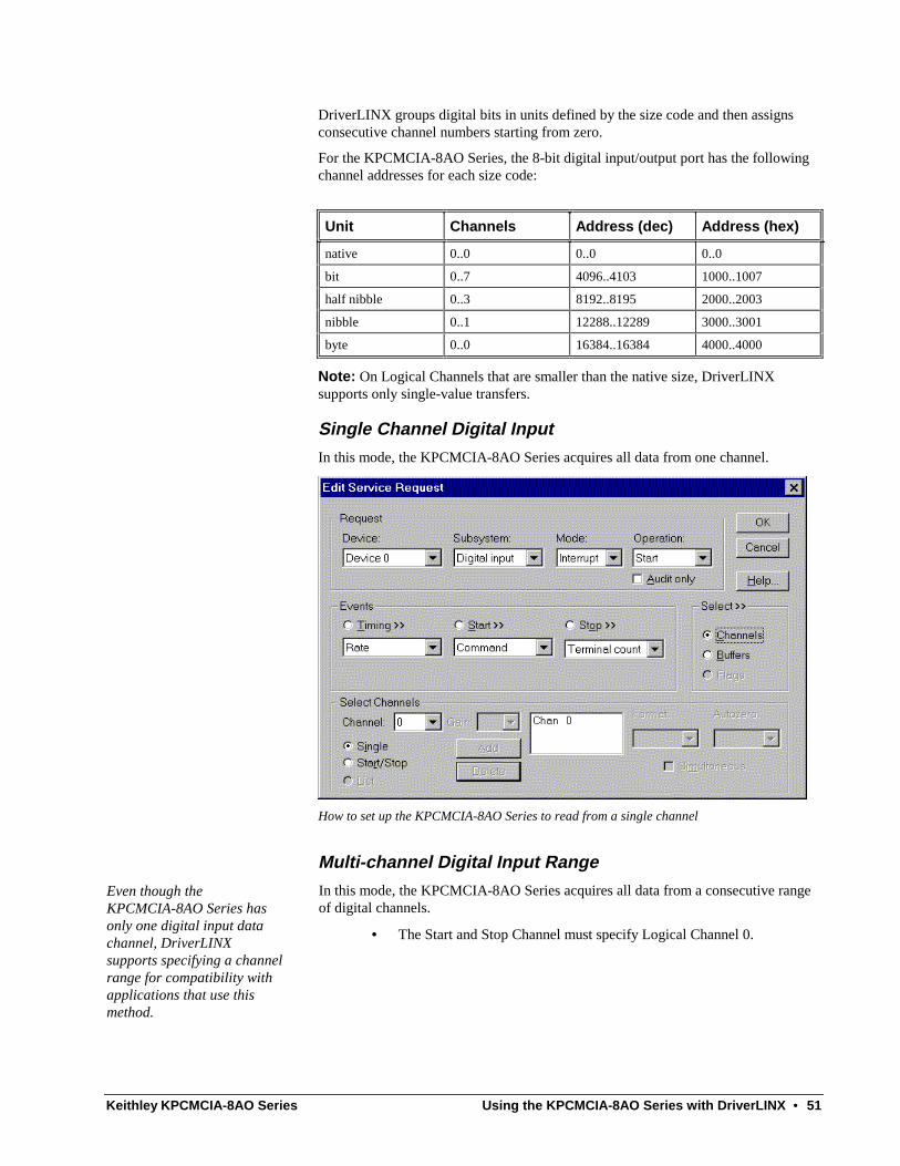
Single Channel Digital Input
In this mode, the KPCMCIA-8AO Series acquires all data from one channel.
How to set up the KPCMCIA-8AO Series to read from a single channel
Multi-channel Digital Input Range
Even though the KPCMCIA-8AO Series has only one digital input data channel, DriverLINX supports specifying a channel range for compatibility with applications that use this method.
In this mode, the KPCMCIA-8AO Series acquires all data from a consecutive range of digital channels.
• The Start and Stop Channel must specify Logical Channel 0.

52 • Using the KPCMCIA-8AO Series with DriverLINX Keithley KPCMCIA-8AO Series
Multi-channel Digital Input List
Even though the KPCMCIA-8AO Series has only one digital input data channel, DriverLINX supports specifying a channel list for compatibility with applications that use this method.
In this mode, the KPCMCIA-8AO Series acquires all data from a random list of digital channels.
• The list can contain only one entry and must specify Logical Channel 0.
Digital Input Buffers DriverLINX supports both single-value digital input and buffered digital input.
• For single-value output, specify the Number of buffers as 0 and the buffer size as 0.
• For buffered output, specify the Number of buffers from 1 to 256 and the buffer size as desired.
How to set up the KPCMCIA-8AO Series to read digital samples using data buffers
An individual DriverLINX buffer may have any size as long as the buffer length holds an integral number of channel scans, i.e., the number of digital input channels you’re acquiring. This restriction enforces the requirement that all input channels have the same number of samples.
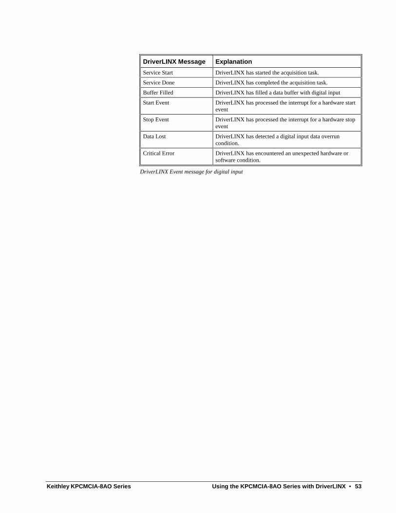
Digital Input Messages For digital input operations, DriverLINX can report the following messages to the application:
Keithley KPCMCIA-8AO Series Using the KPCMCIA-8AO Series with DriverLINX • 53
DriverLINX Message Explanation
Service Start DriverLINX has started the acquisition task.
Service Done DriverLINX has completed the acquisition task.
Buffer Filled DriverLINX has filled a data buffer with digital input
Start Event DriverLINX has processed the interrupt for a hardware start event
Stop Event DriverLINX has processed the interrupt for a hardware stop event
Data Lost DriverLINX has detected a digital input data overrun condition.
Critical Error DriverLINX has encountered an unexpected hardware or software condition.
DriverLINX Event message for digital input

54 • Using the KPCMCIA-8AO Series with DriverLINX Keithley KPCMCIA-8AO Series
Digital Output Subsystem The following sections describe how DriverLINX implements Digital Output Subsystem features for the KPCMCIA-8AO Series.
Digital Output Modes The Digital Output Subsystem supports the following modes:
• Polled—For single value digital output samples.
• Interrupt—For buffered transfers using programmed I/O.
• Other—For subsystem initialization and data conversion.
Digital Output Operations The KPCMCIA-8AO Series Digital Output Subsystem supports the following DriverLINX operations:
• Initialize—aborts any active interrupt data-acquisition tasks and stops the clock. DriverLINX prevents one application process from interfering with another process’s data-acquisition tasks.
• Start—initiates a data-acquisition task using the Mode, Timing, Start, and Stop Events, the Logical Channels, and the Buffers the application specified in the Service Request.
• Status—reports the buffer position of the next sample that DriverLINX will write from a buffer.
• Stop—terminates a digital output data-acquisition task.
• Message—DriverLINX displays a pop-up dialog box for the user containing the text for the current DriverLINX error message.
Digital Output Initialization
By default, the Digital Output subsystem writes zero into the digital output port. You can specify a different initial output value using the Configure DriverLINX Device dialog. See “Digital Output Subsystem Page” on page 19.
Digital Output Timing Events Timing Events specify how the hardware paces or clocks writing Digital Output samples. DriverLINX uses the Timing Event to program when the KPCMCIA-8AO Series writes the next digital output sample to the port.
The KPCMCIA-8AO Series supports the following Timing Events:
• None—Output requires no pacing as DriverLINX is writing only a single value.
• Rate—The KPCMCIA-8AO Series supports only fixed rate digital output using internal and external clocks.
• Digital—DriverLINX uses an external digital input signal to pace the output of each sample.

Keithley KPCMCIA-8AO Series Using the KPCMCIA-8AO Series with DriverLINX • 55
None or Null Event
The Null Event specifies that the task does not need a clock to determine when to write the next sample.
Rate Event
The KPCMCIA-8AO Series supports one type of Rate Event for digital output:
• Rate Generator—Generates a fixed rate clock with equal time intervals between tics.
Rate Generator: Internal Clocking
An internally clocked Rate Generator produces a fixed rate clock with equal time intervals between tics.
Period
Use an internally clocked rate generator when you want to write digital output samples at equally spaced time intervals.
How to set up the KPCMCIA-8AO Series for fixed rate sampling using an internal clock.
For hardware independence, specify the clock channel using the symbolic constant, DEFAULTTIMER, which always maps to the default Logical Channel for digital output timing.
• Specify internal clocking using a Rate Generator on Logical Channel 0 with an Internal 1 Clock source.
• The Period property specifies the time interval between samples in tics, where a tic is 10 µs, or 100 kHz. The minimum period is 1 tic, or 100 kHz. The maximum period is 25600 tics, or 4 Hz. See “Counter/Timer Subsystem” on page 65 for details on the counter/timer channels.

56 • Using the KPCMCIA-8AO Series with DriverLINX Keithley KPCMCIA-8AO Series
Rate Generator: External Clocking
An externally clocked Rate Generator produces a rate clock with unknown time intervals between tics.
Period (ext clk)
Use an externally clocked rate generator when you want to synchronize digital output samples with a recurrent external signal.
How to set up the KPCMCIA-8AO Series for fixed rate sampling using an external clock.
BE SURE that the external clock source is TTL compatible, 0 V minimum to +5 V maximum!
• Specify external clocking using a Rate Generator on Logical Channel 0 with an External or External+ Clock source. External and External+ both specify sampling on the rising, or positive, edge of the external clock signal.
• Users should connect the external clock signal to the EXT_INTR line.
• The Period may be any value ≥ 1 tic, or 10 µs. The period value doesn’t affect the external clock frequency, but DriverLINX requires a valid hardware value in case the application requests a timebase operation and to optimize data transfer between the driver and the application.
Digital Event
DriverLINX supports Digital Events as aliases for externally clocked Rate Generators. Use this technique for compatibility with data-acquisition products that only support externally clock sources.

Keithley KPCMCIA-8AO Series Using the KPCMCIA-8AO Series with DriverLINX • 57
How to set up the KPCMCIA-8AO Series for external rate sampling using a digital event.
Digital Timing Events contain mask, pattern, and match fields. The mask is logically AND with the digital input data on the Logical Channel and then compared against the pattern for a match/mismatch.
BE SURE that the external clock source is TTL compatible, 0 V minimum to +5 V maximum!
• Specify external clocking using Logical Channel 2. For hardware-independence, you can specify the hardware external trigger channel by the symbolic constant, DI_EXTCLK.
• Users should connect the external clock signal to the EXT_INTR line.
• Specify the Mask property as Bit 0 or 1 to indicate that DriverLINX should only compare a 1-bit digital input value against the Pattern property.
• Specify the Match property as Not Equals.
• Specify the Pattern property as 0 for a rising, or positive, edge clock (≠1), or 1 for a falling, or negative, edge clock (≠0).
Digital Output Start Events Start Events specify when the KPCMCIA-8AO Series hardware starts writing digital output data.
The KPCMCIA-8AO Series supports the following Start Events for digital output:
• None—Use this event when the DriverLINX operation doesn’t require a Start Event.
• Command—DriverLINX starts the task on software command, i.e., as soon as DriverLINX finishes programming the KPCMCIA-8AO hardware for the task.
• Digital—The KPCMCIA-8AO starts writing digital output samples when the hardware detects the digital Logical Channel input satisfies the digital condition specified in the Start Event.

58 • Using the KPCMCIA-8AO Series with DriverLINX Keithley KPCMCIA-8AO Series
None or Null Event
The Null Event specifies that the task does not need a Start Event to begin the task.
Command Event
The Command Event starts data acquisition as soon as DriverLINX has completed programming the KPCMCIA-8AO hardware with the task parameters.
Digital Event or Post-Triggering
The KPCMCIA-8AO can write digital output samples after the hardware detects a digital trigger condition. Use post-triggering when you want to synchronize the start of data acquisition with an external signal.
How to set up the KPCMCIA-8AO Series for post-triggered digital output.
Digital Start Events contain mask, pattern, and match fields. The mask is logically AND with the digital input data on the Logical Channel and then compared against the pattern for a match/mismatch.
• Specify the Logical Channel as 0,1 or 2. For hardware-independence, you can specify the hardware external trigger channel by the symbolic constant, DI_EXTTRG.
• Specify the Mask property to indicate that DriverLINX should only compare selected bits in the digital input value against the Pattern property.
• Specify the Match property as Equals to trigger on an exact match of the digital pattern to the masked digital input. Match on Not Equals triggers on any difference between the masked digital input and the Pattern.
• Specify the Pattern property to compare with the masked digital input value.

Keithley KPCMCIA-8AO Series Using the KPCMCIA-8AO Series with DriverLINX • 59
• Specify the Delay property as any number of samples from 0 to 232-1.
Digital Output Stop Events Stop Events specify when the KPCMCIA-8AO Series hardware stops writing digital output data.
The KPCMCIA-8AO Series supports the following Stop Events for digital output:
• None—Use this event when the DriverLINX operation doesn’t require a Stop Event.
• Command—DriverLINX stops the task on software command, i.e., when the application issues a Service Request with a Stop operation.
• Terminal count—DriverLINX stops the task after the KPCMCIA-8AO Series hardware has written all the data buffers once.
• Digital—The KPCMCIA-8AO stops the task when the hardware detects the digital Logical Channel input satisfies the digital condition specified in the Stop Event.
None or Null Event
The Null Event specifies that the task does not need a Stop Event to end the task.
Command Event
The Command Event stops data acquisition when the user application changes the Operation property in the Service Request to Stop and resubmits the Service Request to DriverLINX.
In stop on command mode, DriverLINX continuously cycles through all the data buffers writing to the digital port on the KPCMCIA-8AO Series.
Terminal Count Event
The Terminal Count Event stops data acquisition after DriverLINX has written the digital output data from all the data buffers once. Use terminal count when you want to write a fixed amount of data.
Digital Event or Pre-Triggering
The KPCMCIA-8AO can write digital output samples until the hardware detects a digital trigger condition. Use pre-triggering when you want to synchronize the end of data acquisition with an external signal.
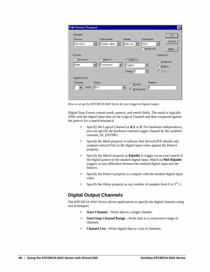
60 • Using the KPCMCIA-8AO Series with DriverLINX Keithley KPCMCIA-8AO Series
How to set up the KPCMCIA-8AO Series for pre-triggered digital output.
Digital Stop Events contain mask, pattern, and match fields. The mask is logically AND with the digital input data on the Logical Channel and then compared against the pattern for a match/mismatch.
• Specify the Logical Channel as 0,1 or 2. For hardware-independence, you can specify the hardware external trigger channel by the symbolic constant, DI_EXTTRG.
• Specify the Mask property to indicate that DriverLINX should only compare selected bits in the digital input value against the Pattern property.
• Specify the Match property as Equals to trigger on an exact match of the digital pattern to the masked digital input. Match on Not Equals triggers on any difference between the masked digital input and the Pattern.
• Specify the Pattern property to compare with the masked digital input value.
• Specify the Delay property as any number of samples from 0 to 232-1.
Digital Output Channels The KPCMCIA-8AO Series allows applications to specify the digital channels using two techniques:
• Start Channel—Write data to a single channel.
• Start/Stop Channel Range—Write data to a consecutive range of channels.
• Channel List—Write digital data to a list of channels.

Keithley KPCMCIA-8AO Series Using the KPCMCIA-8AO Series with DriverLINX • 61
Digital Output Logical Channels
The KPCMCIA-8AO Series has a single digital output port that DriverLINX designates as Logical Channel 0.
Extended Logical Channel Addressing
DriverLINX supports a software extension to Logical Channel addressing that allows applications to combine adjacent Logical Channels into a single channel or split a Logical Channel into smaller addressable parts. For instance, applications can address individual bits of a digital port or read and write multiple ports as a single value.
To use the Logical Channel addressing extensions, form a 16-bit Logical Channel address by combining the channel number of an addressable unit with a size field as follows:
0 Size Code Channel Number
15 14 13 12 11 10 9 8 7 6 5 4 3 2 1 0
MSB LSB
The following table specifies the 3-bit size codes:
Size Code Unit Bits
0 native varies with hardware
1 bit 1
2 half nibble 2
3 nibble 4
4 byte 8
5 word 16
6 dword 32
7 qword 64
“Native” units refer to the hardware-defined digital channel size. For most boards, this is the same as an 8-bit byte. When using extended Logical Channel addressing, DriverLINX groups digital bits in units defined by the size code and then assigns consecutive channel numbers starting from zero.

62 • Using the KPCMCIA-8AO Series with DriverLINX Keithley KPCMCIA-8AO Series
For the KPCMCIA-8AO Series, the 8-bit digital input/output port has the following channel addresses for each size code:
Unit Channels Address (dec) Address (hex)
native 0..0 0..0 0..0
bit 0..7 4096..4103 1000..1007
half nibble 0..3 8192..8195 2000..2003
nibble 0..1 12288..12289 3000..3001
byte 0..0 16384..16384 4000..4000
Note: On Logical Channels that are smaller than the native size, DriverLINX supports only single-value transfers.
Single Channel Digital Output
In this mode, the KPCMCIA-8AO Series writes all data to one channel.
How to set up the KPCMCIA-8AO Series to write a single digital output channel
Multi-channel Digital Output Range
Even though the KPCMCIA-8AO Series has only one digital output channel, DriverLINX supports specifying a channel range for compatibility with applications that use this method.
In this mode, the KPCMCIA-8AO Series writes all data to a consecutive range of digital channels.
• The Start and Stop Channel must specify Logical Channel 0.

Keithley KPCMCIA-8AO Series Using the KPCMCIA-8AO Series with DriverLINX • 63
Multi-channel Digital Output List
Even though the KPCMCIA-8AO Series has only one digital output channel, DriverLINX supports specifying a channel list for compatibility with applications that use this method.
In this mode, the KPCMCIA-8AO Series writes all data to a random list of digital channels.
• The list can contain only one entry and must specify Logical Channel 0.
Digital Output Buffers DriverLINX supports both single-value digital output and buffered digital output.
• For single-value output, specify the Number of buffers as 0 and the buffer size as 0.
• For buffered output, specify the Number of buffers from 1 to 256 and the buffer size as desired.
How to set up the KPCMCIA-8AO Series to write digital output using data buffers
An individual DriverLINX buffer may have any size as long as the buffer length holds an integral number of channel scans, i.e., the number of digital output channels you’re acquiring. This restriction enforces the requirement that all output channels have the same number of samples.
Digital Output Messages For digital output operations, DriverLINX can report the following messages to the application:

64 • Using the KPCMCIA-8AO Series with DriverLINX Keithley KPCMCIA-8AO Series
DriverLINX Message Explanation
Service Start DriverLINX has started the acquisition task.
Service Done DriverLINX has completed the acquisition task.
Buffer Filled DriverLINX has written all data in the buffer
Start Event DriverLINX has processed the interrupt for a hardware start event
Stop Event DriverLINX has processed the interrupt for a hardware stop event
Data Lost DriverLINX has detected a digital output data overrun condition.
Critical Error DriverLINX has encountered an unexpected hardware or software condition.
DriverLINX Event messages for digital output

Keithley KPCMCIA-8AO Series Using the KPCMCIA-8AO Series with DriverLINX • 65
Counter/Timer Subsystem The KPCMCIA-8AO Series has a single counter/timer, which is for internal use only. DriverLINX defines a counter/timer channel for pacing input/output subsystems but doesn’t support independent counter/timer applications.
The following table lists the Counter/Timer Subsystem’s Logical Channels and shows their allowable clock sources, modes and gates.
Logical Clocks Modes Gates
Channel Source Tic Period
0 — On-board event timer
Internal 1 10 µs (100 kHz) Rate Gen Disabled
Internal 2 10 µs (100 kHz) No Connect
Internal 3 1 ms (1 kHz)
External
External+
Counter/Timer Subsystem Logical Channels and Allowed Clocks, Modes and Gates
On-Board Event Timer
The On-Board Event Timer (Logical Channel 0) is an 8-bit counter combined with a 2-range prescaler that supports both internal and external clock sources. The hardware limits its use to pacing input/output tasks only. It does not support independent counter/timer tasks.
Internal Clocking
The KPCMCIA-8AO Series has a master oscillator with two prescaler outputs to pace input/output tasks. DriverLINX defines the following internal clock sources for this Logical Channel:
• Internal 1—specifies a clock source that allows the full range of output frequencies, from 4 Hz to 100 kHz. With this clock source each tic is 10 µs.
• Internal 2— specifies the 100 kHz clock source, which allows output frequencies from 393 Hz to 100 kHz. With this clock source each tic is 10 µs.
• Internal 3— specifies the 1 kHz clock source, which allows output frequencies from 4 Hz to 1 kHz. With this clock source each tic is 1 ms.
Applications that wish to control the prescaler selection should choose Internal 2 or Internal 3 as the clock source to specify a prescaler and use a tic count from 1 to 256.

66 • Using the KPCMCIA-8AO Series with DriverLINX Keithley KPCMCIA-8AO Series
External Clocking
The KPCMCIA-8AO Series allows an external clock source to pace input/output tasks. DriverLINX defines the following external clock sources for the On-Board Event Timer:
• External, External+ —specify sampling on the rising, or positive, edge of the external clock signal.
Clocking Modes
The On-Board Event Timer can operate in only one mode. DriverLINX defines the following clock mode for this Logical Channel:
• Rate Generator—specifies sampling of one channel (or all channels simultaneously) in the scan list at each tic of an internal or external clock source.
Gating
The On-Board Event Timer doesn’t have a gate control. Select Disabled or No Connect for the Gate Status of Rate Events.
Counter/Timer Interrupt
The KPCMCIA-8AO Series supports counter/timer interrupts indirectly. You can set up an INTERRUPT mode analog output task with a single sample buffer. Buffer Filled messages notify your application of the counter/ timer interrupt.

Keithley KPCMCIA-8AO Series Uninstalling DriverLINX • 67
Uninstalling DriverLINX
How do I uninstall DriverLINX? DriverLINX consists of three separate component installations:
• DriverLINX for Keithley KPCMCIA
• DriverLINX Programming Interfaces
• DriverLINX Documentation
You can uninstall the last two installations at any time without interfering with compiled applications that require DriverLINX drivers. To uninstall the latter components, run the “Add/Remove Programs” tool in the Windows Control Panel.
To uninstall DriverLINX drivers for the Keithley KPCMCIA, you must
• Disable the DriverLINX driver.
• Shut down your computer to remove the hardware.
• Reboot your computer to unload the driver.
• Run the DriverLINX uninstall program.
How to Disable a DriverLINX Driver in Windows NT
1. From the Windows Start menu, select “Settings”, then “Control Panel”. Left click on the DriverLINX Configuration icon in the Control Panel.
2. Select the KPCMCIA devices you want to disable.
3. Right click on each device and select “Disabled” on the popup menu.
4. Repeat steps 2-3 for each KPCMCIA card that you are uninstalling.
5. Close the DriverLINX Configuration Panel.
6. When finished, shut down your computer and physically remove any installed KPCMCIA hardware.
7. Reboot Windows.
8. To finish uninstalling, see “How to Remove DriverLINX for the Keithley KPCMCIA Series” on page 71.

68 • Uninstalling DriverLINX Keithley KPCMCIA-8AO Series
How to Disable a DriverLINX Driver in Windows 95/98/Me/2000
1. From the Windows Start menu, select “Settings”, then “Control Panel”. Left click on the System icon in the Control Panel. Select the “Device Manager” tab in the System Properties dialog.
2. Left click the “+” icon next to “DriverLINX drivers” to display the installed Keithley KPCMCIA devices.
3. Select the KPCMCIA device you want to disable.
4. Click the “Remove” button.
5. In the “Confirm Device Removal” dialog, select “OK”.
6. Repeat steps 3-5 for each KPCMCIA card or driver that you uninstalling.
7. When finished, click “Close”, shut down your computer, and physically remove any installed KPCMCIA hardware.
8. Reboot Windows.
9. To finish uninstalling, see “How to Remove DriverLINX for the Keithley KPCMCIA Series” on page 71. Also, see “How to disable the DriverLINX Setup Information files in Windows 95/98” on page 68 to ensure Windows does not try to re-install the DriverLINX driver the next time you insert your card.
How to disable the DriverLINX Setup Information files in Windows 95/98/Me/2000
Windows saves a copy of all Setup Information files (.INF) that it has ever used to install device drivers. Deleting the .INF file will ensure that Windows does not attempt reinstall the DriverLINX driver the next time you insert the card. Unfortunately, the different versions of Windows 95/98/Me/2000 (retail, service pack 1 (Win 95A), and OEM (Win 95B)) use different naming conventions and storage locations for Setup Information files. The following protocol should work for all versions of Windows.
1. Using the My Computer icon, open your “Windows” folder and select the “Inf” folder.

Keithley KPCMCIA-8AO Series Uninstalling DriverLINX • 69
2. Right-click the “Inf” folder and select “Find…” on the pop-up menu.
3. In the “Find: All Files” dialog, make sure the “Include subfolders” option is checked on the “Name & Location” page.
4. Select the “Advanced” tab.
5. Enter “Keithley” in the edit box labeled “Containing text:”.
6. Select “Find Now” and Windows will search for all files containing the text, “Keithley”.

70 • Uninstalling DriverLINX Keithley KPCMCIA-8AO Series
7. The search will return one or more files. Look for files with the type labeled “Setup Information”.
8. Open each Setup Information file by double-clicking it.
9. If the file does not contain a Scientific Software Tools copyright or the “[Version]” section does not have an entry, “Class=DriverLINX”, close it and repeat from Step 8 until you’ve examined all Setup Information files.
10. If the file contains a Scientific Software Tools copyright and the “[Version]” section has an entry, “Class=DriverLINX”, then you must determine if this Setup Information file controls the KPCMCIA
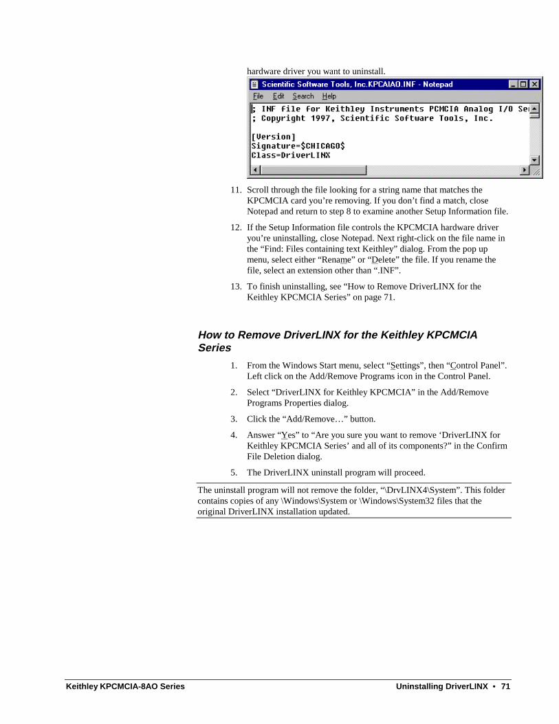
Keithley KPCMCIA-8AO Series Uninstalling DriverLINX • 71
hardware driver you want to uninstall.
11. Scroll through the file looking for a string name that matches the KPCMCIA card you’re removing. If you don’t find a match, close Notepad and return to step 8 to examine another Setup Information file.
12. If the Setup Information file controls the KPCMCIA hardware driver you’re uninstalling, close Notepad. Next right-click on the file name in the “Find: Files containing text Keithley” dialog. From the pop up menu, select either “Rename” or “Delete” the file. If you rename the file, select an extension other than “.INF”.
13. To finish uninstalling, see “How to Remove DriverLINX for the Keithley KPCMCIA Series” on page 71.
How to Remove DriverLINX for the Keithley KPCMCIA Series
1. From the Windows Start menu, select “Settings”, then “Control Panel”. Left click on the Add/Remove Programs icon in the Control Panel.
2. Select “DriverLINX for Keithley KPCMCIA” in the Add/Remove Programs Properties dialog.
3. Click the “Add/Remove…” button.
4. Answer “Yes” to “Are you sure you want to remove ‘DriverLINX for Keithley KPCMCIA Series’ and all of its components?” in the Confirm File Deletion dialog.
5. The DriverLINX uninstall program will proceed.
The uninstall program will not remove the folder, “\DrvLINX4\System”. This folder contains copies of any \Windows\System or \Windows\System32 files that the original DriverLINX installation updated.

72 • Troubleshooting Keithley KPCMCIA-8AO Series
Troubleshooting
Solving Problems Correct operation of your KPCMCIA hardware requires successful completion of four steps.
1. Windows finds free resources for the KPCMCIA card.
2. You configure the KPCMCIA drivers using the DriverLINX Configuration Panel.
3. Windows loads the KPCMCIA drivers into memory.
If you are having a problem installing or configuring your KPCMCIA product, review the following notes. If these notes do not solve your problem, or your problem is not described, then contact technical support and fully describe your problem.
Solving Problems Installing Drivers On Windows NT, the DriverLINX installation program reliably installs and registers the DriverLINX drivers. On Windows 95/98/Me, the DriverLINX installation program runs a wizard that guides you through installing the DriverLINX drivers. If the wizard did not complete all steps, click here to run it again.
Solving Problems Configuring the Drivers Windows 95/98/Me/2000 assigns hardware resources for the KPCMCIA, but you must still configure the KPCMCIA drivers before using them. The DriverLINX configuration requires that you select the hardware model of your KPCMCIA card. And, on Windows NT, you must manually enter the address and interrupt resource assignments. See “Configure DriverLINX Device Dialog” on page 9 for more information.

Keithley KPCMCIA-8AO Series Troubleshooting • 73
Solving Problems Loading Drivers Before the KPCMCIA drivers can load, you must
1. Install the DriverLINX software.
2. Install the KPCMCIA hardware into your computer.
3. Configure DriverLINX.
4. Reboot your computer.
If you have not completed the above steps, please do so before proceeding.
On Windows NT you must determine free hardware resources for the KPCMCIA using Windows NT Diagnostics . On Windows 95/98/Me/2000, the operating system will automatically assign hardware resources to the KPCMCIA cards. Automatic resource assignment can fail sometimes on
• Older PCI computers.
• Computers with ISA cards installed.
• Computers with no free hardware resources.
Sorting through all possibilities can be a challenge due to the sheer number of combinations of hardware designs, PC plug-in boards, and versions of Windows. The following sections will help you gather information about why a driver may have failed to load. This information is essential for you or technical support to solve your problem.
Did the DriverLINX Driver Load?
1. Run “DriverLINX Configuration” from Windows Control Panel.
2. Select the “DriverLINX” tab.
3. Click the “+” icon next to DriverLINX to expand the list of drivers, if necessary.
4. Select “Keithley KPCMCIA-8AO Series”. Click “+”, if necessary, to expand the list.
5. Select the line with the number of the Logical Device you configured. If the number does not exist, you did not configure the driver. See “Configure DriverLINX Device Dialog” on page 9.
6. Click the “Properties…” button and then select the “General” tab.
7. Do you see “Status: Device Loaded”? If not, did you reboot the computer after configuring? If not, reboot now and repeat the above steps.

74 • Troubleshooting Keithley KPCMCIA-8AO Series
8. If you rebooted the computer after configuring and Windows did not load your device, see “Checking for Device Errors” on page 74.
Checking for Device Errors
When a DriverLINX kernel driver cannot load, it usually writes an explanation into the system event log. You can view this log under Windows 95/98/Me/2000 or Windows NT using the DriverLINX Event Viewer.
Windows 95/98/Me/2000 maintains additional driver information in the Device Manager. Also see “Getting More Driver Information on Windows 95/98” on page 74.
1. Run “DriverLINX Event Viewer” from the DriverLINX folder.
2. Click on the “+” icon next to “DriverLINX” in the left panel.
3. Select the abbreviation for your driver.
4. Does the first line in the right panel show a current error?
5. Double click on the error line to see more detail and an explanatory message.
6. If you cannot resolve the problem yourself, please provide this error information when contacting technical support.
Getting More Driver Information on Windows 95/98/Me/2000
Windows 95/98/Me/2000 reports additional information about device status using the Device Manager. To access this utility,
1. Right click on “My Computer” and then select “Properties”.
2. Select “Device Manager” and “View devices by type”.
3. Does “DriverLINX drivers” appear in the list? If not, see “Solving Problems Installing Drivers” on page 72.
4. Click the “+” next to “DriverLINX drivers”.
5. Does your KPCMCIA product appear in the list? If not, see “Solving Problems Installing Drivers” on page 72.
6. Does the icon next to your KPCMCIA product display an exclamation point (!)? If no, Windows has loaded your KPCMCIA driver.

Keithley KPCMCIA-8AO Series Troubleshooting • 75
7. Select the line with the “!” and then click “Properties”.
8. The General tab will show the reason why the driver did not load. For the KPCMCIA Series a possible problem is “This device cannot find enough free resources that it can use. If you want to use this device, you will need to disable one of the other devices on this system. (Code 12).” In this case, you usually need to free an interrupt, such as by disabling COM2, if unused.
9. The Resources tab will show if Windows detected an unresolvable hardware conflict.
Getting More Driver Information on Windows NT
On Windows NT, the only reasons that a driver does not load are
• You did not install the driver software.
• You did not correctly configure the driver.
• You changed the driver startup parameters.
An incorrectly configured driver will report the reasons that it failed to load into the Windows Event Log. See “Checking for Device Errors” on page 74 for more information.
On Windows NT, DriverLINX drivers load automatically during system boot. An administrator can change the startup command for any NT driver to either “manual” or “disabled”.
1. Run “DriverLINX Configuration” from Windows Control Panel.
2. Select the “DriverLINX” tab.
3. Click the “+” icon next to DriverLINX to expand the list of drivers, if necessary.
4. Select “Keithley KPCMCIA-8AO Series”. Click “+”, if necessary, to expand the list.
5. Select the line with the number of the Logical Device that did not load.
6. Right click the mouse to see a popup menu.
7. Select “Automatic” to instruct Windows to load the driver the next time you reboot.

76 • Troubleshooting Keithley KPCMCIA-8AO Series
Generating a DriverLINX Configuration Report Your DriverLINX installation includes a troubleshooting tool that generates a report of your DriverLINX configuration. If you call Technical Support, after reading “Solving Problems” on page 72, they may ask you to generate and e-mail this report to help you solve installation and configuration problems.
What is in the Report? The troubleshooting tool analyzes your computer to obtain information about DriverLINX and operating system software that would assist Technical Support in troubleshooting a problem you are having. It includes information on DriverLINX files, environment variables, registry entries, hardware and the operating system.
How do I Generate the Report? You can easily generate the report by clicking this shortcut . Once the troubleshooting tool generates the report, you will have the opportunity to review it and make deletions, if desired, before e-mailing it to Technical Support. If you do not have direct access to e-mail, you can save the report to a disk file and send a copy later. A Technical Support engineer will guide you through these steps when you are asked to send a report.

Keithley KPCMCIA-8AO Series Glossary of Terms • 77
Glossary of Terms
A/D Abbreviation for analog-to-digital, a process that converts a continuous analog signal into a discrete digital approximation of the analog signal.
ADC Abbreviation for analog-to-digital converter, the hardware that performs the A/D conversion process.
API Abbreviation for Application Programming Interface. An API defines the syntax of the data structures and functions of software services.
Buffer A block of memory used to receive data from a data-acquisition device or to write data to a data-acquisition device.
Bus mastering A hardware technique that allows a device on the PCI bus to initiate a direct data transfer with memory or another device. The logic for controlling the transfer resides on the PCI device, not the system board. See also “DMA”.
Clocking A periodic pulse or signal that data-acquisition hardware uses to read or write the next sample or block of samples. Also referred to as “pacing”.
D/A Abbreviation for digital-to-analog, a process that converts a discrete digital value into a continuous analog voltage representing that value.
78 • Glossary of Terms Keithley KPCMCIA-8AO Series
DAC Abbreviation for digital-to-analog converter, the hardware that performs the D/A conversion process.
DMA Abbreviation for Direct Memory Access, a technique where the system board can transfer data between a device and memory without using the CPU. In the PC, a standard chip on the system board controls the transfer. See also “bus mastering”.
Event For DriverLINX, an event is the occurrence of a signal that clocks, starts, or stops a data-acquisition task.
Gating A signal that enables and disables another signal or data-acquisition task depending on the value of the gate signal.
IRQ Abbreviation for interrupt request. Peripheral hardware signals the CPU that it is ready to transfer data.
ISA Abbreviation for Industry Standard Architecture. A standard for the original IBM AT bus specification that defines the bus structure, CPU and support chip architecture, and the clock frequency of the ISA bus.
ISR Abbreviation for interrupt service routine, the software function inside a device driver that handles interrupt requests.
Logical Device DriverLINX’s designation for a specific data-acquisition board inside your computer.
Messages In Windows and DriverLINX, a message notifies the application about the state of a process.
Modes DriverLINX data-acquisition techniques.

Keithley KPCMCIA-8AO Series Glossary of Terms • 79
Operations Allowed DriverLINX data-acquisition commands.
Pacing A periodic pulse or signal that data-acquisition hardware uses to read or write the next sample or block of samples. Also referred to as “clocking”.
PCI Abbreviation for Peripheral Component Interconnect. PCI refers to a specification for a high-speed common local bus on a system board.
PCMCIA Abbreviation for Personal Computer Memory Card International Association. PCMCIA established a specification for miniaturized cards and sockets for installing peripheral device in portable personal computers called PC Card. PCMCIA sometimes refers to PC Card.
Process Refers to the collection of data and code segments and hardware resources that the operating system assigns to one application.
Service Request A DriverLINX object or data structure that completely defines a data-acquisition task.
Subsystem DriverLINX subdivides a general purpose data-acquisition device into six subsystems—Device, Analog Input, Analog Output, Digital Input, Digital Output, and Counter/Timer.
Triggering The technique of using a pulse or signal to start or stop a data-acquisition task.
TTL Abbreviation for transistor-transistor logic, a family of digital logic elements.