Embed Size (px)
Citation preview

Keep Your Cool with Heat
Exchangers
Heat Transfer eHANDBOOK
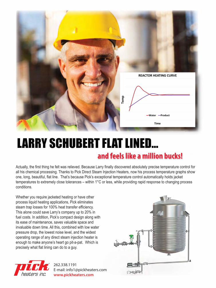
Actually, the first thing he felt was relieved. Because Larry finally discovered absolutely precise temperature control for all his chemical processing. Thanks to Pick Direct Steam Injection Heaters, now his process temperature graphs show one, long, beautiful, flat line. That’s because Pick’s exceptional temperature control automatically holds jacket temperatures to extremely close tolerances – within 1°C or less, while providing rapid response to changing process conditions.
Whether you require jacketed heating or have other process liquid heating applications, Pick eliminates steam trap losses for 100% heat transfer efficiency. This alone could save Larry’s company up to 20% in fuel costs. In addition, Pick’s compact design along with its ease of maintenance, saves valuable space and invaluable down time. All this, combined with low water pressure drop, the lowest noise level, and the widest operating range of any direct steam injection heater is enough to make anyone’s heart go pit-a-pat. Which is precisely what flat lining can do to a guy.
Larry finally discovered absolutely precise temperature control for
and feels like a million bucks!LARRY SCHUBERT FLAT LINED...
® 262.338.1191E-mail: [email protected]
REACTOR HEATING CURVE
Water Product
TimeTemp
TABLE OF CONTENTSConsider Open-Rack Seawater Heat Exchangers 4
Such units often offer an attractive way to take advantage of the resource
Pick the Right Side 11
Allocating fluids in a tubular exchanger demands care
Take a Closer Look at Direct Steam Injection 14
Technology responds rapidly to changing process conditions
Additional Resources 16
AD INDEXPick Heaters • www.pickheaters.com 2
Heat Transfer eHANDBOOK: Keep Your Cool with Heat Exchangers 3
www.ChemicalProcessing.com
Heat exchangers that use seawater
are common worldwide because
they provide a compelling benefit
— seawater is a free heat-transfer medium
that doesn’t produce emissions. The units
exchange heat between a process fluid
(cryogenic or hot) and seawater of ambi-
ent temperature. In warm sea conditions
(i.e., water at >14°C or, better, >18°C),
such a seawater stream can serve as the
heat source in vaporizer/heater equip-
ment. On the other hand, cold seawater
(preferably <12°C) can handle cooling of
hot process streams; even seawater in
tropical climes might suffice to cool some
process streams.
Many seawater heat exchangers are
open-rack designs because they typi-
cally boast better economics and shorter
payback periods than other options
such as shell-and-tube units. This advan-
tage holds particularly true for large
high-flow and high-capacity equipment.
Another key plus is that open-rack heat
exchange is considered a very safe and
reliable technology. The units provide a
simple and cost-efficient heat exchange
process that’s easy to operate and main-
tain. Plants usually use parallel operating
exchangers with spares.
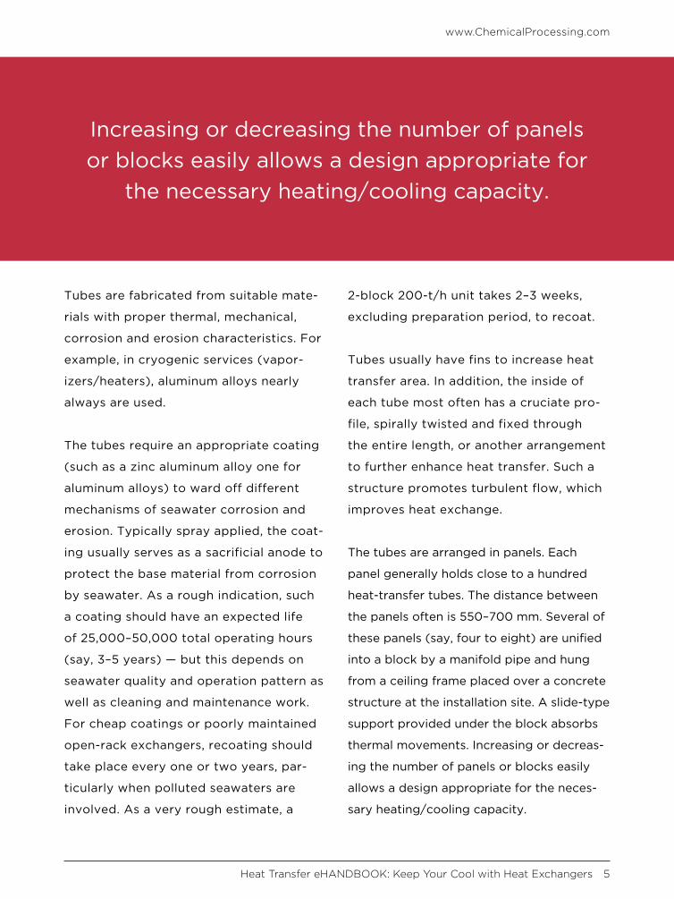
MECHANICAL DETAILSIn an open-rack heat exchanger, the
seawater enters at the top and runs
downward in a film-like manner over
tubes containing the process fluid. The
seawater collects in a basin at the bottom
of the tubes and then is returned to
the sea.
Consider Open-Rack Seawater Heat ExchangersSuch units often offer an attractive way to take advantage of the resource
By Amin Almasi, mechanical consultant
Heat Transfer eHANDBOOK: Keep Your Cool with Heat Exchangers 4
www.ChemicalProcessing.com
Tubes are fabricated from suitable mate-
rials with proper thermal, mechanical,
corrosion and erosion characteristics. For
example, in cryogenic services (vapor-
izers/heaters), aluminum alloys nearly
always are used.
The tubes require an appropriate coating
(such as a zinc aluminum alloy one for
aluminum alloys) to ward off different
mechanisms of seawater corrosion and
erosion. Typically spray applied, the coat-
ing usually serves as a sacrificial anode to
protect the base material from corrosion
by seawater. As a rough indication, such
a coating should have an expected life
of 25,000–50,000 total operating hours
(say, 3–5 years) — but this depends on
seawater quality and operation pattern as
well as cleaning and maintenance work.
For cheap coatings or poorly maintained
open-rack exchangers, recoating should
take place every one or two years, par-
ticularly when polluted seawaters are
involved. As a very rough estimate, a
2-block 200-t/h unit takes 2–3 weeks,
excluding preparation period, to recoat.
Tubes usually have fins to increase heat
transfer area. In addition, the inside of
each tube most often has a cruciate pro-
file, spirally twisted and fixed through
the entire length, or another arrangement
to further enhance heat transfer. Such a
structure promotes turbulent flow, which
improves heat exchange.
The tubes are arranged in panels. Each
panel generally holds close to a hundred
heat-transfer tubes. The distance between
the panels often is 550–700 mm. Several of
these panels (say, four to eight) are unified
into a block by a manifold pipe and hung
from a ceiling frame placed over a concrete
structure at the installation site. A slide-type
support provided under the block absorbs
thermal movements. Increasing or decreas-
ing the number of panels or blocks easily
allows a design appropriate for the neces-
sary heating/cooling capacity.
Increasing or decreasing the number of panels or blocks easily allows a design appropriate for
the necessary heating/cooling capacity.
www.ChemicalProcessing.com
Heat Transfer eHANDBOOK: Keep Your Cool with Heat Exchangers 5
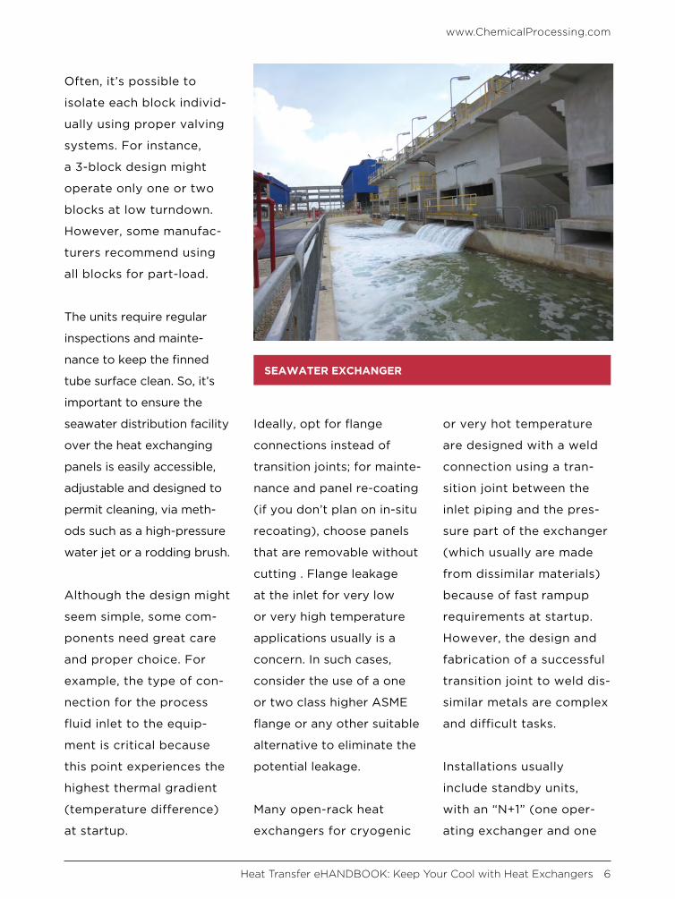
Often, it’s possible to
isolate each block individ-
ually using proper valving
systems. For instance,
a 3-block design might
operate only one or two
blocks at low turndown.
However, some manufac-
turers recommend using
all blocks for part-load.
The units require regular
inspections and mainte-
nance to keep the finned
tube surface clean. So, it’s
important to ensure the
seawater distribution facility
over the heat exchanging
panels is easily accessible,
adjustable and designed to
permit cleaning, via meth-
ods such as a high-pressure
water jet or a rodding brush.
Although the design might
seem simple, some com-
ponents need great care
and proper choice. For
example, the type of con-
nection for the process
fluid inlet to the equip-
ment is critical because
this point experiences the
highest thermal gradient
(temperature difference)
at startup.
Ideally, opt for flange
connections instead of
transition joints; for mainte-
nance and panel re-coating
(if you don’t plan on in-situ
recoating), choose panels
that are removable without
cutting . Flange leakage
at the inlet for very low
or very high temperature
applications usually is a
concern. In such cases,
consider the use of a one
or two class higher ASME
flange or any other suitable
alternative to eliminate the
potential leakage.
Many open-rack heat
exchangers for cryogenic
or very hot temperature
are designed with a weld
connection using a tran-
sition joint between the
inlet piping and the pres-
sure part of the exchanger
(which usually are made
from dissimilar materials)
because of fast rampup
requirements at startup.
However, the design and
fabrication of a successful
transition joint to weld dis-
similar metals are complex
and difficult tasks.
Installations usually
include standby units,
with an “N+1” (one oper-
ating exchanger and one
SEAWATER EXCHANGER
www.ChemicalProcessing.com
Heat Transfer eHANDBOOK: Keep Your Cool with Heat Exchangers 6
spare) or “N+2” (two spares) configu-
ration common. Plants requiring high
reliability and availability usually opt for
a N+2 arrangement. You should maintain
standby exchangers in operating condi-
tion, ready for startup when required.
AVOIDING PROBLEMSThe exchanger should operate stably,
reliably and safely without any vibration
or problem within its specified operat-
ing range. You usually should expect the
manufacturer to guarantee continuous
operation from 10% to 110% of capacity.
Some open-rack units have experienced
high vibration during transient or part-
load operation. So, consider studies and
proper measures to avoid high vibra-
tion when operating under transient
conditions and within the entire part-
load range.
To prevent induced vibration, reinforce
the support of the piping around equip-
ment (upstream and downstream) to
increase the natural frequency above
the typical 10 or 12 Hz. In addition,
these applications always benefit from
high-stiffness piping designs. Of course,
accurate simulations and dynamic studies
are the best ways to determine potential
risks of component failure from vibration,
fatigue from thermal cycling and other
damage mechanisms.
Operation in very cold or very hot
applications often results in complex
phenomena such as the icing of seawa-
ter (for cryogenic applications) or the
boiling of seawater (for hot fluids) on the
external surface of the initial section of
tubes (where the maximum temperature
difference exists). This can cause diffi-
culties in design, mechanical analysis and
operation. Because the heat exchanger
usually handles a significant difference in
temperature and needs a rapid startup or
shutdown, thermal stresses and transient
operations require appropriate consider-
ation. A variety of studies (such as those
by finite element methods) and tests can
lead to highly durable structures. Today’s
methods enable design of the most
suitable tubes (e.g., sizes and internal/
A stress analysis can ensure a design provides proper flexibility and minimizes loads on panel
connections and other critical components.
www.ChemicalProcessing.com
Heat Transfer eHANDBOOK: Keep Your Cool with Heat Exchangers 7

external surface shapes). Design pres-
sures of 50, 75 or 100 barg or more aren’t
uncommon for such exchangers.
A stress analysis can ensure a design
provides proper flexibility and minimizes
loads on panel connections and other
critical components. Most often, the mag-
nitudes of thermal stresses depend on the
deformation of the inlet header, which has
a higher cross-sectional rigidity than that
of the heat transfer tubes. Based on dif-
ferent studies and observations, maximum
thermal stresses often appear during peak
running and imm ediately after process
fluid flow is stopped. Thermal stresses at
welded (including transition) joints and
heat affected zones of heat transfer tubes
should remain within allowable limits.
You also must consider possible thermal
stresses of the panels due to different
malfunction scenarios. For instance, poor
seawater distribution can result in some
unexpected thermal stresses. So, finite
element studies for the panel design to
check the stresses at the transition joints
and headers usually are needed.
MODERN DESIGNSDuring operation, the highest tube tem-
perature gradient occurs on the outer
wall at the initial part of each tube. As
already noted, in vaporizer/heater units,
the temperature could be lower than the
freezing point of seawater, prompting ice
buildup on the tubes. Especially in cold
climates, the ice thickness and height
could increase significantly, causing sub-
stantial resistance to heat transfer. On
the other hand, for open-rack coolers,
the temperature might exceed the boiling
point of seawater. Use advanced designs
to avoid this icing/boiling problem and
the ensuing degraded performance.
Some manufacturers have developed
duplex pipe structures at the initial part
of tubes to suppress icing/boiling on the
outer surface of the tube. The process
fluid feeds into both an inner tube section
and annular channel between inner and
outer sections of the tube. The process
fluid’s flow rate in the inner tube usually
equals that in the annular channel. Inside
the annular channel, process fluid directly
exchanges heat with the seawater. How-
ever, because of lower mass rates, this
doesn’t cause thermal shock and boiling/
freezing. Meanwhile, process fluid in the
inner tube exchanges heat with the fluid
in the annular channel. These gradual heat
exchanges allow better control of tempera-
ture and prevent ice forming or boiling on
the surface of the heat transfer tube.
Modern duplex pipe structures provide
significantly improved thermal per-
formance; they reduce the volume of
seawater required by 10–15%. In addi-
tion, they decrease area requirements
to 30–45% of those of conventional
www.ChemicalProcessing.com
Heat Transfer eHANDBOOK: Keep Your Cool with Heat Exchangers 8
exchangers, and cut operating cost by
10–20%.
THE SEAWATER SIDEThe steel frame and all surfaces in con-
tact with seawater require proper material
selection and coating. Usually this means
choice of an appropriate grade of stain-
less steel. For some applications with
“clean” seawater, duplex or other common
stainless steels suffice. Other applica-
tions relying on polluted or dirty seawater
demand better materials such as super
duplex stainless steels.
It’s sensible to install side panels to pre-
vent any projection of seawater to the
outside of the equipment.
To control algae growth within the
system, inject sodium hypochlorite, chlo-
rine or similar chemicals into the seawater
before it passes to the exchanger.
Seawater contamination and pollution
can degrade the operation and reliability
of the exchangers. For instance, sea-
water containing significant amounts
of heavy metal ions can shorten the life
of the protective coating of tubes; the
metal ions attack such coatings. Seawater
loaded with sand and suspended solids
can lead to sediment jamming the water
trough and the tube panel. The design
of the seawater intake filtration system
should prevent silts, sands and sea life
from reaching the seawater pumps and
exchangers. (For an unusual case of
exchanger plugging, see “Don’t Neglect
Spring Cleaning Duties,” http://bit.
ly/2JbeEE7.)
You also must consider the impact of the
unit on marine life. The large volumes of
seawater used could have an adverse
effect. In addition, the cooled/heated and
treated seawater discharged back to the
source potentially could impair marine life
and overall seawater quality. Any open-rack
heat exchanger system also poses several
minor environmental issues, including sea-
water intake and seawater outfall. Improper
design could prompt a major breach of
environmental rules with serious conse-
quences. Good design can forestall such
issues. Seawater discharge temperature
You also must consider the impact of the unit on marine life.
www.ChemicalProcessing.com
Heat Transfer eHANDBOOK: Keep Your Cool with Heat Exchangers 9
should comply with local regulation; most
jurisdictions limit the temperature change
to 5°C or 10°C. Also, pay attention to the
locations of the seawater intake and outfall
to avoid cold/hot seawater recirculation.
A CASE STUDYA plant needed a 400-t/h capacity open-
rack vaporizer for a cryogenic service.
This led to a design that uses 90 tubes per
panel, four panels per block, and four blocks
per unit. Each panel block has a capacity of
100 t/h. Normal inlet pressure of the cryo-
genic liquid to this vaporizer is around 48
barg. The design pressure is considered
80 barg. The vaporizer requires around
8,000 t/h of seawater. As a rough indica-
tion, the estimated heat exchanged is 90
MW. In other words, this open-rack vapor-
izer system is a massive unit to exchange
90 MW.
Empty weight of each panel block is
around 8 t; empty weight of the equip-
ment unit with the four blocks and
including manifolds, headers, seawater
troughs, inner maintenance deck, etc., is
approximately 65 t. Operating weight of
the unit is around 110 t.
AMIN ALMASI is a mechanical consultant based in
Sydney, Australia. Email him at [email protected].
Improper design could prompt a major breach of environmental rules with serious consequences.
www.ChemicalProcessing.com
Heat Transfer eHANDBOOK: Keep Your Cool with Heat Exchangers 10
When designing a shell-and-tube
exchanger, one of the first
issues is deciding which fluid
should go on the shell side and which on
the tube side. So, let’s look at some rules-
of-thumb for several key factors, realizing
such rough guidelines won’t cover all cases.
High pressure. Put a high-pressure fluid on the
tube side. This usually minimizes exchanger
cost. The smaller tube diameter has a higher
pressure rating for the same metal thickness
compared to the larger diameter shell.
Fouling. A fluid with a tendency to foul
generally should go on the tube side. Clean-
ing straight tubes normally is easier than
cleaning the shell — even if a relatively
large tube pitch or a square tube pattern is
used to make the shell side easier to clean.
However, the exchanger configuration sig-
nificantly influences the choice. Using a
fixed tubesheet mandates putting a clean
fluid on the shell side; unless expected foul-
ing is easily removed by chemical cleaning,
the fixed tubesheet makes the shell side
impossible to clean. In contrast, U-tubes
are more difficult than straight tubes to
clean. So, sending a normally fouling service
through the shell side may be better if foul-
ing reduction steps, such as installation of
helical baffles, are suitable.
Expensive materials. Put a corrosive fluid
on the tube side. That way, only the tubes,
tubesheets, heads and channels will need
expensive corrosion-resistant alloys. In
contrast, a corrosive fluid on the shell
side requires the entire exchanger to use
the materials.
Pick the Right SideAllocating fluids in a tubular exchanger demands care
By Andrew Sloley, Contributing Editor
Heat Transfer eHANDBOOK: Keep Your Cool with Heat Exchangers 11
www.ChemicalProcessing.com
Low pressure drop. The fluid should go on
the shell side. An appropriate combination
of baffle cut, spacing and type (segmen-
tal, double segmental, rod-baffle, etc.) can
accommodate nearly any pressure-drop
requirement. Services under vacuum almost
always are on the shell side because of
pressure drop sensitivity.
Vapor services. Because a vapor normally
has a higher volume and lower heat-trans-
fer coefficient than a liquid, allocate it to
the shell side. This reduces pressure drop
for a given volume and typically provides a
higher heat-transfer coefficient.
Condensing services. A condensing fluid
most often goes on the shell side — but
the choice demands careful evaluation.
If the shell-side velocity is low enough,
the vapor and liquid can separate inside
the exchanger. The liquid dropping out
makes the vapor leaner, reducing the
temperature required to get more liquid
to condense from the remaining vapor.
For relatively pure mixtures, this effect
is unimportant.
For wide-condensing-range mixtures, ensure
the overall flow pattern inside the exchanger
keeps the liquid and vapor mixed. This may
necessitate having the shell-side fluid leave
from the bottom (forcing the liquid and
vapor to mix) or determine the choice of
baffling inside the exchanger (horizontal
versus vertical or 45° baffle cut).
Viscous services. Here, the tradeoffs are com-
plex. A viscous fluid on the tube side tends
to have high pressure drop and low heat
transfer. That favors shell-side allocation.
However, high pressure drop on the shell
side can prompt significant flow by-passing
around baffles, reducing heat transfer. A shell
side with a high pressure drop also may suffer
from vibration damage; shell-side modifica-
tions (assuming the user is aware of the need
for them) can reduce such damage.
Solidifying services. Generally avoid a shell-
and-tube exchanger for any service with a
high risk of solidification or freezing. How-
ever, if you must use such an exchanger, I
suggest putting the fluid with a risk of solid-
ification in the tubes. If the fluid solidifies,
For fouling services, the exchanger configuration significantly influences the choice.
www.ChemicalProcessing.com
Heat Transfer eHANDBOOK: Keep Your Cool with Heat Exchangers 12
you usually can pull out the tube bundle and
replace it. In contrast, if the solid is on the
shell side, it’s often impossible to remove
the tube bundle. The entire exchanger may
require replacement.
However, allocating to the shell side a fluid
that may freeze may offer advantages. In
some cases, externally heating the shell with
electric tracing may enable melting the fluid
enough to get the exchanger back into service.
In either allocation, a freezing fluid can
create local plugs. If its velocity drops,
the fluid may approach the temperature
of the other side of the exchanger, which
may cause the fluid to set solid. This can
occur on the shell side next to baffles on
the shell edge. It also can happen in tubes.
Tubes may differ in flow rates. A tube with
a low flow rate may reach a lower tem-
perature, making it more likely to freeze
or set up. Often, exchangers with freez-
ing fluids may have large areas where the
exchanger has set solid.
ANDREW SLOLEY, Contributing Editor, asloley@
putman.net
If the solid is on the shell side, it’s often impossible to remove the tube bundle. The entire exchanger may require replacement.
www.ChemicalProcessing.com
Heat Transfer eHANDBOOK: Keep Your Cool with Heat Exchangers 13
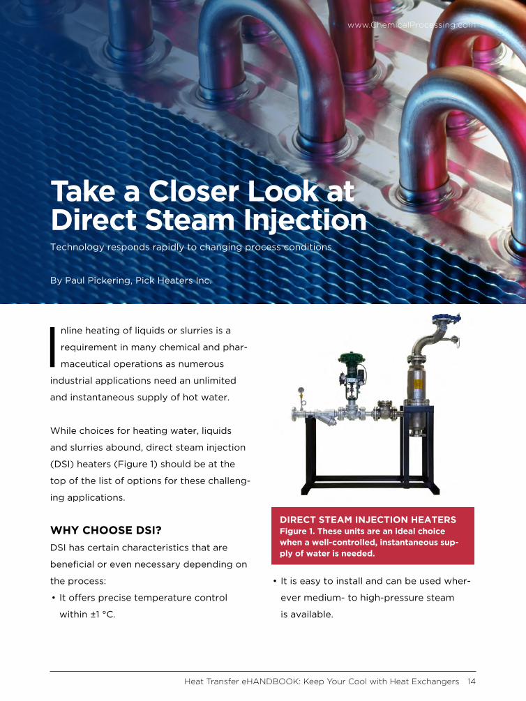
Inline heating of liquids or slurries is a
requirement in many chemical and phar-
maceutical operations as numerous
industrial applications need an unlimited
and instantaneous supply of hot water.
While choices for heating water, liquids
and slurries abound, direct steam injection
(DSI) heaters (Figure 1) should be at the
top of the list of options for these challeng-
ing applications.
WHY CHOOSE DSI? DSI has certain characteristics that are
beneficial or even necessary depending on
the process:
• It offers precise temperature control
within ±1 °C.
• It is easy to install and can be used wher-
ever medium- to high-pressure steam
is available.
Take a Closer Look at Direct Steam InjectionTechnology responds rapidly to changing process conditions
By Paul Pickering, Pick Heaters Inc.
DIRECT STEAM INJECTION HEATERSFigure 1. These units are an ideal choice when a well-controlled, instantaneous sup-ply of water is needed.
Heat Transfer eHANDBOOK: Keep Your Cool with Heat Exchangers 14
www.ChemicalProcessing.com
• Precisely machined variable orifice injector
with spring-loaded piston eliminates dam-
aging vibration and steam hammer.
• Compared to alternatives such as tank
steam sparging or indirect heat exchang-
ers, DSI heaters can cut fuel costs by as
much as 28% because the liquid absorbs
100% of the available energy (BTUs) from
the steam instantly.
• It features a low liquid-side pressure drop
— less than 2 psi.
• It is environmentally safe and nonflamma-
ble, unlike heat transfer fluids that require
special handling and constant monitoring.
EXAMPLES OF DSI IN INDUSTRIAL PROCESSESDSI is better than indirect exchangers for
heating water in industrial applications
because it provides a rapid response to
changing process conditions and enables
precise temperature control within a single
degree Celsius. As such, DSI heating is suit-
able for a variety of industrial processes as
illustrated in the following examples:
• Many processes in the chemical industry
require water temperature to be controlled
precisely before adding it to a batch
process. A DSI system provides instant
temperature control, reducing the cycle
time and increasing productivity.
• DSI also is ideal for heating large-capacity,
closed-loop jacketed vessels, tanks and
blenders; mixing two condensate steams;
or even dispersing gas into a liquid.
• Applications such as plant sanitization,
clean-in-place (CIP) and washdown hose
stations require hot process water. Instan-
taneous and accurately controlled hot
water must be available to meet stringent
plant demands.
• In pharmaceutical processing, DSI tech-
nology is used in such applications as the
continuous-flow heat treatment of bio-
waste. The precise temperature control
enables wastewater with living cells to
be killed or inactivated and then cooled
before disposal. For example, one waste
steam inactivation system required the
waste from multiple reactors to be heated
to 140 °C, held for a period of time and
then cooled to 60 °C. Read more here.
PAUL PICKERING is a writer for Pick Heaters Inc. Pick
Heaters produces DSI heaters in 10 standard sizes for
liquid flow rates up to 5,000 gpm, and steam flow rates
from 150 lb/hr to 50,000 lb/hr. For more information,
visit www.pickheaters.com/Products.htm.
DSI provides a rapid response to changing process conditions and enables precise temperature
control within a single degree Celsius.
www.ChemicalProcessing.com
Heat Transfer eHANDBOOK: Keep Your Cool with Heat Exchangers 15
Visit the lighter side, featuring draw-
ings by award-winning cartoonist
Jerry King. Click on an image and you
will arrive at a page with the winning
caption and all submissions for that
particular cartoon.
ADDITIONAL RESOURCESEHANDBOOKSCheck out our vast library of past eHandbooks that offer a
wealth of information on a single topic, aimed at providing
best practices, key trends, developments and successful
applications to help make your facilities as efficient, safe,
environmentally friendly and economically competitive
as possible.
UPCOMING AND ON DEMAND WEBINARSTap into expert knowledge. Chemical Processing editors
and industry experts delve into hot topics challenging
the chemical processing industry today while providing
insights and practical guidance. Each of these free webi-
nars feature a live Q&A session and lasts 60 minutes.
WHITE PAPERSCheck out our library of white papers covering myriad
topics and offering valuable insight into products and solu-
tions important to chemical processing professionals. From
automation to fluid handling, separations technologies and
utilities, this white paper library has it all.
MINUTE CLINICChemical Processing’s Minute Clinic podcast series is
designed to tackle one critical issue at a time — giving you
hard-hitting information in just minutes.
ASK THE EXPERTSHave a question on a technical issue that needs to be
addressed? Visit our Ask the Experts forum. Covering
topics from combustion to steam systems, our roster of
leading subject matter experts, as well as other forum
members, can help you tackle plant issues.
TOP COMICAL PROCESSING
JOIN US ON SOCIAL MEDIA!
Heat Transfer eHANDBOOK: Keep Your Cool with Heat Exchangers 16